SLOFEC LS120 Pipe Inspection · Client a SLOFEC™ LS120 Pipe Inspection Page 8 of 13 6” pipeline...
71
SLOFEC LS120 Pipe Inspection Client: Client a Facility: Site b Items Inspected: 6” pipeline Inspection Method: SLOFEC Commencement Date: 14 th April 2016 Completion Date: 19 th April 2016 Type of Report: Final Report Number: K00x-16US Job Number: J00x-16US Unit 1, Howe Moss Avenue Unit 27-28 Kirkhill Industrial Estate, Dyce Webb Ellis Industrial Park Aberdeen, AB21 0GP Rugby, CV21 NP United Kingdom United Kingdom Tel : +44 (0)1224-724744 Tel : +44 (0)1788-547294 Fax : +44 (0)1224-774087 Fax : +44 (0)1788-547299 WWW.INNOSPECTION.COM
Transcript of SLOFEC LS120 Pipe Inspection · Client a SLOFEC™ LS120 Pipe Inspection Page 8 of 13 6” pipeline...
SLOFEC LS120 Pipe Inspection
Client: Client a
Facility: Site b
Items Inspected: 6” pipeline
Inspection Method: SLOFEC
Commencement Date: 14th April 2016
Completion Date: 19th April 2016
Type of Report: Final
Report Number: K00x-16US
Job Number: J00x-16US
Unit 1, Howe Moss Avenue Unit 27-28
Kirkhill Industrial Estate, Dyce Webb Ellis Industrial Park
Aberdeen, AB21 0GP Rugby, CV21 NP
United Kingdom United Kingdom
Tel : +44 (0)1224-724744 Tel : +44 (0)1788-547294
Fax : +44 (0)1224-774087 Fax : +44 (0)1788-547299
W W W . I N N O S P E C T I O N . C O M
OPS132 – Rev. 4 © 2016 Innospection Ltd
Client a SLOFEC™ LS120 Pipe Inspection Page 1 of 13
6” pipeline Final Report K00x-16xx
SLOFECTM PIPE / VESSEL INSPECTION REPORT
(LS120)
OPS132 – Rev. 4 © 2016 Innospection Ltd
Client a SLOFEC™ LS120 Pipe Inspection Page 2 of 13
6” pipeline Final Report K00x-16xx
Executive Summary Innospection Ltd was requested by Client a, to conduct a SLOFEC™ (Saturation Low Frequency Eddy Current) inspection on the 6” LPG to LSFO pipeline. The inspection was conducted at the site b on 14th April 2016 and was completed on 19th April 2016. This inspection report documents in detail the specific inspection that has been conducted; the individual technique and equipment utilised, and the results, observations and conclusions obtained. Indications above 40% wall loss were deemed as significant and instructed by Client to be directly marked on the pipeline. The SLOFEC™ inspection indicated no significant defects above 40%. Four sections (22, 40, 48 & 49) of this pipeline were found to have isolated random indications with 20%-30% wall loss. The inspection was carried out with the assistance of rope access and scissor lift, resulting in many short sections of scanned areas. The specific pipeline had many adjacent pipelines and welds which the scanner couldn’t pass resulting in a dead-zone for SLOFEC™. Where the painted surface had broken down topside scale was present – this scale produced an out of phase signal in the SLOFEC™ software. All spurious signals have been removed from the BMP images present within this report.

OPS132 – Rev. 4 © 2016 Innospection Ltd
Client a SLOFEC™ LS120 Pipe Inspection Page 3 of 13
6” pipeline Final Report K00x-16xx
Table of Contents 1. Test Object Data .............................................................................................................. 4
2. Inspection Task ................................................................................................................ 4
3. Inspection Personnel ........................................................................................................ 4
4. Inspection Volume ............................................................................................................ 5
5. Inspection Equipment ....................................................................................................... 5
5.1. SLOFEC™ Equipment ........................................................................................... 5
5.2. Ultrasonic Equipment ............................................................................................. 6
6. SLOFEC™ Equipment Setting ......................................................................................... 6
7. SLOFEC™ Equipment Calibration ................................................................................... 7
7.1. Equipment Calibration ............................................................................................ 7
7.2. Calibration Control ................................................................................................. 7
7.3. Calibration Samples ............................................................................................... 8
7.4. Change of Settings ................................................................................................ 8
8. Inspection Procedures ...................................................................................................... 8
9. Inspection Performance ................................................................................................... 8
9.1. Scanner Movement ................................................................................................ 8
9.2. Scan Track Positioning .......................................................................................... 9
9.3. Parameter Storage ................................................................................................ 9
10. Defect Analysis ................................................................................................................ 9
11. Comments to Inspection ................................................................................................... 9
12. Result Overview ............................................................................................................. 10
12.1. Sensitivity Settings ............................................................................................... 10
12.2. Result Overview ................................................................................................... 10
13. Inspection Summary....................................................................................................... 12
14. Documentation ............................................................................................................... 12
15. Signature ........................................................................................................................ 13
Appendix Appendix 1 : Scanned Sections 1-59
OPS132 – Rev. 4 © 2016 Innospection Ltd
Client a SLOFEC™ LS120 Pipe Inspection Page 4 of 13
6” pipeline Final Report K00x-16xx
1. Test Object Data Object Identification : 6” Pipeline
Location of Object : 123
Orientation of Scan : Longitudinal
Wall Thickness : Nominal 7.11mm
Material : Carbon Steel
Surface Condition :
Generally clean and free from loose debris – painted surface. Some areas the painted surface had broken down and topside scale was present and required light scraping.
2. Inspection Task As requested by Client a, a SLOFEC™ (Saturation Low Frequency Eddy Current) inspection was performed on the 6” pipeline located at site b from 14th April 2016 to 19th April 2016. The inspection was performed with a SLOFEC™ technology scanner, type LS120. SLOFEC™ is regarded as a fast corrosion screening technique, detecting corrosion on either side of the wall inspected. This method of testing makes it practical to inspect the pipes from the external surface, whilst they are still in service and at operating temperatures. The SLOFEC™ inspection team consisted of qualified engineers from Innospection Ltd. All areas described in Section 4 − Inspection Volume were inspected with the SLOFEC™ scanner. The inspection was carried out as a general inspection.
3. Inspection Personnel Inspection Operator : Technician a
PCN L2 ET/UT - 000000
Inspection Assistant : Technician b PCN L2 ET - 000000
OPS132 – Rev. 4 © 2016 Innospection Ltd
Client a SLOFEC™ LS120 Pipe Inspection Page 5 of 13
6” pipeline Final Report K00x-16xx
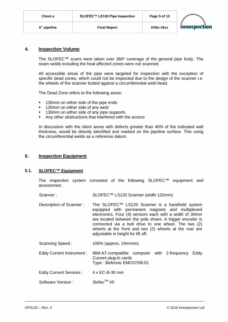
4. Inspection Volume The SLOFEC™ scans were taken over 360º coverage of the general pipe body. The seam welds including the heat affected zones were not scanned. All accessible areas of the pipe were targeted for inspection with the exception of specific dead zones, which could not be inspected due to the design of the scanner i.e. the wheels of the scanner butted against a circumferential weld bead. The Dead Zone refers to the following areas: 130mm on either side of the pipe ends 130mm on either side of any weld 130mm on either side of any pipe supports Any other obstructions that interfered with the access In discussion with the client areas with defects greater than 40% of the indicated wall thickness, would be directly identified and marked on the pipeline surface. This using the circumferential welds as a reference datum.
5. Inspection Equipment
5.1. SLOFEC™ Equipment The inspection system consisted of the following SLOFEC™ equipment and accessories: Scanner : SLOFEC™ LS120 Scanner (width 120mm)
Description of Scanner : The SLOFEC™ LS120 Scanner is a handheld system
equipped with permanent magnets and multiplexed electronics. Four (4) sensors each with a width of 30mm are located between the pole shoes. A trigger encoder is connected via a belt drive to one wheel. The two (2) wheels at the front and two (2) wheels at the rear are adjustable in height for lift off.
Scanning Speed : 100% (approx. 24m/min)
Eddy Current Instrument : IBM-AT-compatible computer with 2-frequency Eddy Current plug-in cards Type : Beltronic EMC07/08.01
Eddy Current Sensors : 4 x EC-B-30 mm
Software Version : SlofecTM V5

OPS132 – Rev. 4 © 2016 Innospection Ltd
Client a SLOFEC™ LS120 Pipe Inspection Page 6 of 13
6” pipeline Final Report K00x-16xx
Cable : 20 metres of specific cable connection between the computer Eddy Current instrument and SLOFEC™ LS120 Scanner
Reference Plate : 7.11mm from Innospection, Serial No. 267
Reference Defect : 20%, 40%, 60%, 80% FBH
5.2. Ultrasonic Equipment The Ultrasonic equipment consisted of the following accessories: Panametrics-NDT EPOCH 4 Ultrasonic Flaw Detector Serial No. 110097203 Capable of both “A” scan display and digital thickness readout 5.0 MHz 10mm Ø twin crystal transducer 2mm – 12mm carbon steel calibration step wedge
6. SLOFEC™ Equipment Setting In general, the SLOFEC™ system is calibrated using sample test samples with artificial reference defects. The reference samples should be of the same material and thickness as the surface to be inspected. In the case of a coating being present on the surface to be inspected, the average thickness of the coating (if applicable) should also be simulated on the reference sample for the calibration. Typical reference defects that are used are flat bottom holes or conical bottom holes having a diameter of 5mm, 10mm and 20mm. The depths of the artificial reference defects are typically 20%, 40%, 60%, 80% and 100%. For calibration, the SLOFEC™ system is driven over the reference defects and the channels are set (one sensor per channel) to give a sufficient sensitivity level for the detection of internal and external corrosion defects. The calibration is performed at the beginning, after breaks, at the end of every shift and when significant changes are made to the settings of the equipment. The calibration results and reference defect data from the calibration sample is always stored in the system. The Eddy Current signal analysis is done online. The computerised equipment and the software allow the analysis of the signal amplitude [in div.] and signal phase [in °].

OPS132 – Rev. 4 © 2016 Innospection Ltd
Client a SLOFEC™ LS120 Pipe Inspection Page 7 of 13
6” pipeline Final Report K00x-16xx
In discussion with the individual client, indications comparable with the reference defect indications can be marked on the pipeline and are usually recommended to be re-inspected by Ultrasonic (UT) examination.
7. SLOFEC™ Equipment Calibration
7.1. Equipment Calibration For internal corrosion detection, the differential mode was used. The frequency setting used for Channel 1−4 (differential mode) was 80−100 kHz. The amplitude of the signals was set so that the artificial reference defect (Ø 8mm 80% depth) was set to 8 screen divisions. This is only classed as the initial pre-calibration setup and may then be further adjusted when the first true indication is detected and evaluated for depth, this by utilising the Ultrasonic pulse echo technique. Optimum signal/noise ratio and signal phase separation between the internal defect indications and other indications were considered when selecting a suitable test frequency. The differential channels of all the sensors were set so that internal defects were indicated in the vertical signal phase direction as shown in the diagram below. By moving the scanner in the positive forward direction, the internal defect signal would show the first peak down, followed by the second peak up with an upward movement.
7.2. Calibration Control The general setting and calibration was performed at the beginning of the inspection and all the calibration data was stored digitally. Calibration controls were performed at the beginning and end of each working shift as well as after any other significant interruption (i.e. breaks or lunch). Re-calibration is also deemed necessary when significant changes are made to the settings of the equipment.
Sample signal display of internal defect

OPS132 – Rev. 4 © 2016 Innospection Ltd
Client a SLOFEC™ LS120 Pipe Inspection Page 8 of 13
6” pipeline Final Report K00x-16xx
Calibration samples are used for the initial set-up and for the random check of operator’s settings. Accuracy of sensitivity settings can only be evaluated and achieved, when the first true indication found on the item undergoing the test is verified by an UT operator, with the corresponding depth of indication and SLOFEC™ sensitivity being adjusted accordingly. With this setting, external corrosion defects would be detected and distinguished by phase separation from the internal defects.
7.3. Calibration Samples The calibration samples are manufactured by Innospection Ltd in accordance to the setting standard requirements.
7.4. Change of Settings In the event of any scanner adjustment, re-calibration is performed.
8. Inspection Procedures The inspection was performed according to the following valid procedure: SLOFEC™ Pipe Procedure No. InnoPSloPIP-001-08 – Current Issue
9. Inspection Performance
9.1. Scanner Movement The scanner assistant, who was in permanent communication with the SLOFEC™ operator, was responsible for positioning and moving the scanner on the pipe surface. The SLOFEC™ LS120 Scanner is marked clearly on the top with the FORWARD and BACKWARD directions so that all scan directions are made clear to the operator and assistant at all times. The use of Bluetooth headsets was required for communication between technician, assistant and rope access team. The scanner was moved manually with the scanned tracks being overlapped at all times. All scans for the inspection were recorded in the forward position.

OPS132 – Rev. 4 © 2016 Innospection Ltd
Client a SLOFEC™ LS120 Pipe Inspection Page 9 of 13
6” pipeline Final Report K00x-16xx
9.2. Scan Track Positioning The pipelines were marked circumferentially into 5 equal tracks. The tracks were numbered in a clockwise direction while facing the direction of flow. Where no longitudinal seam weld was present, the top of the pipeline was used a reference.
9.3. Parameter Storage The Eddy Current testing parameter was set during the calibration and digitally stored according to the scan direction and lift off.
10. Defect Analysis All indications which showed a clear signal phase direction similar to that of the reference defects and had signal amplitude equivalent to that of the test piece were subjected to analysis. Signals that are clearly out of the corrosion phase direction were not reported.
11. Comments to Inspection
The pipeline was generally clean however, some areas of the painted surface had broken down and topside scale was present. This required rope access to gently scrape this surface away to reduce spurious signals observed in the SLOFEC software. The pipeline was within a pipe rack with many adjacent pipelines. Where the adjacent pipelines were in close proximity to the line being inspected, this restricted the scanner and certain tracks were not possible to scan.

OPS132 – Rev. 4 © 2016 Innospection Ltd
Client a SLOFEC™ LS120 Pipe Inspection Page 10 of 13
6” pipeline Final Report K00x-16xx
12. Result Overview
12.1. Sensitivity Settings The general overview of the inspected areas with the results is presented in the attached colour scan reports with wall loss being represented in colour classes as shown in the Wall Loss Legend below:
Note Eddy Current inspection is an evaluation method of NDT; hence all results obtained are based upon the test piece used. Material and wall thickness of the test piece should be as near as reasonably practicable to the item under inspection. Artificial defects should be as near in size and shape as to the type sought. Because SLOFEC™ signal amplitudes are an indication of defect depth and volume, the defect depth analysis by signal amplitude can only be done in comparison with artificial reference defects having varying depths.
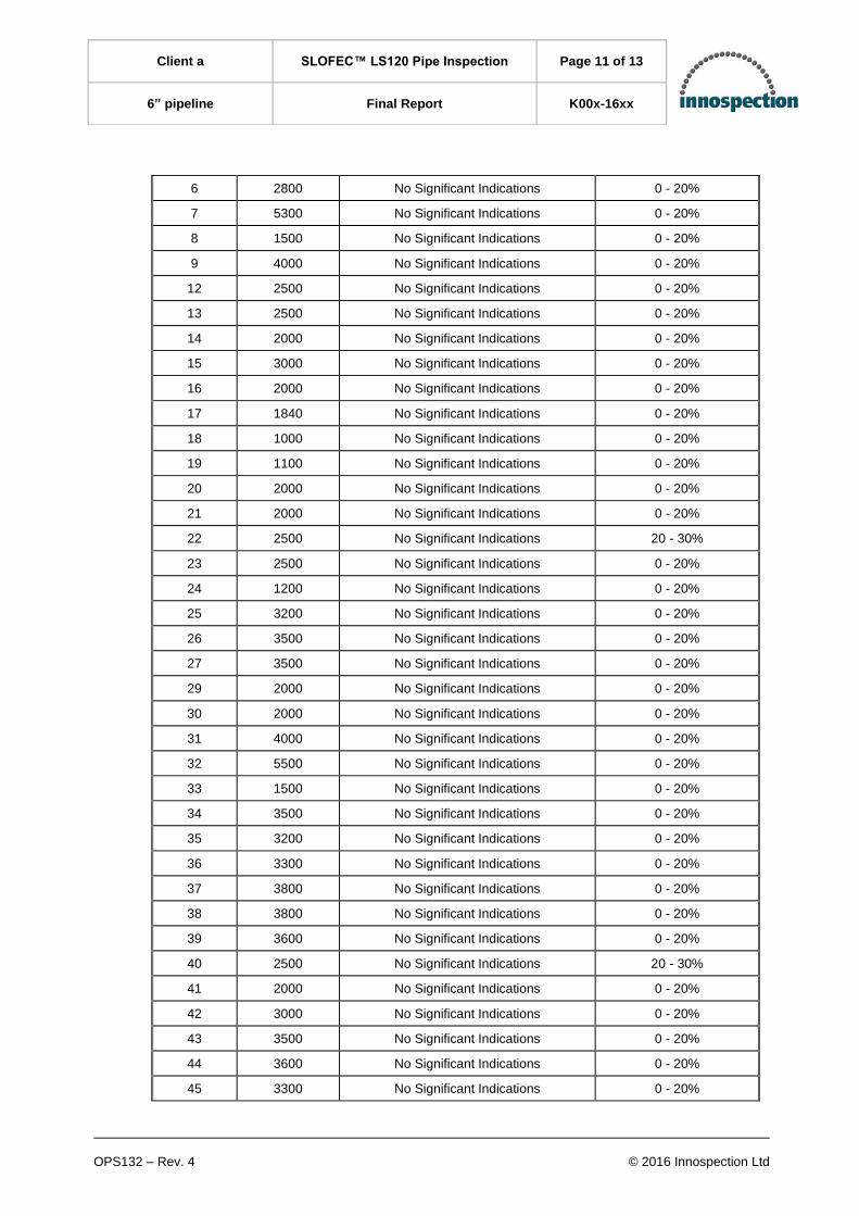
12.2. Result Overview A summary of the inspection findings in each of the scanned section is given below:
Pipe Section
No. Pipe Length
(mm) Comments Max % Wall Loss in Pipe Section
1 2000 No Significant Indications 0 - 20%
2 2000 No Significant Indications 0 - 20%
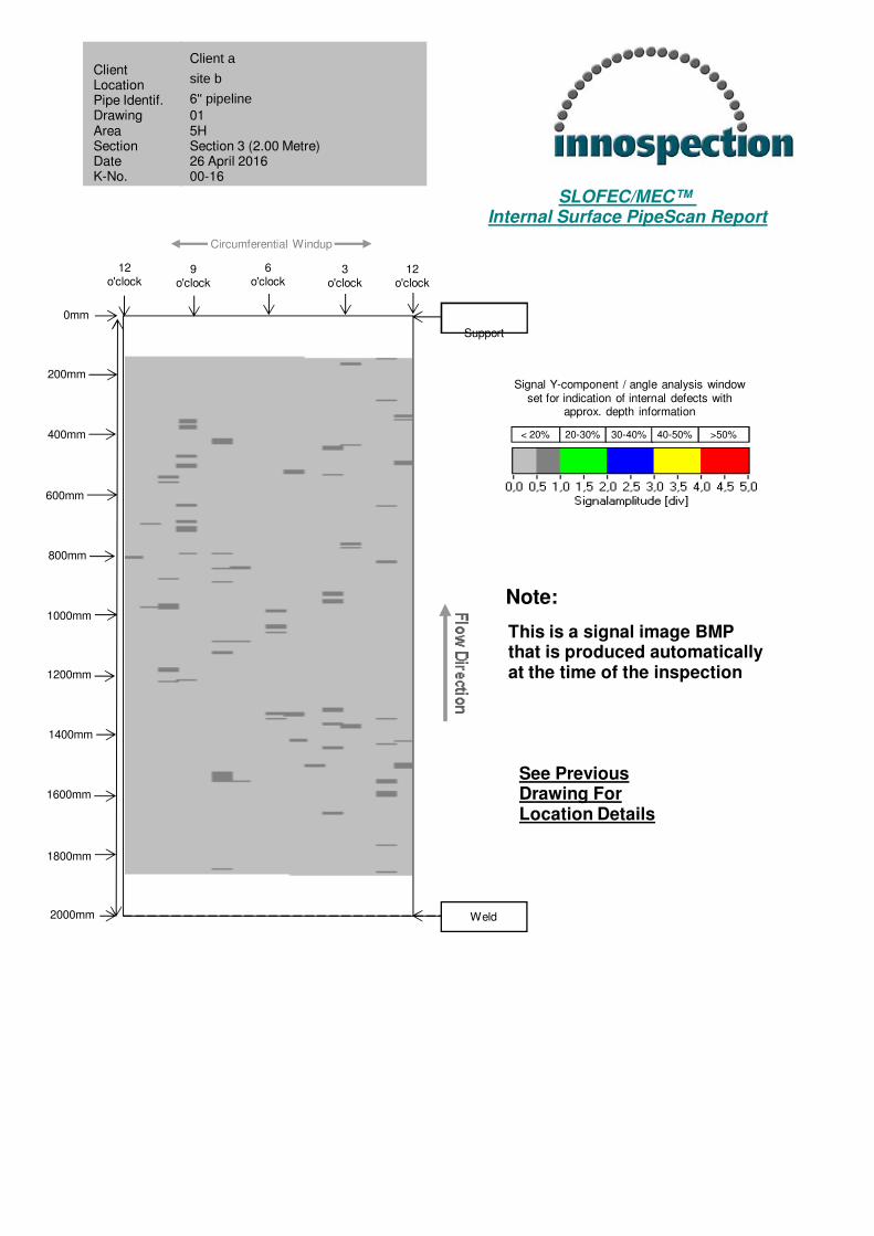
3 2000 No Significant Indications 0 - 20%
4 2000 No Significant Indications 0 - 20%
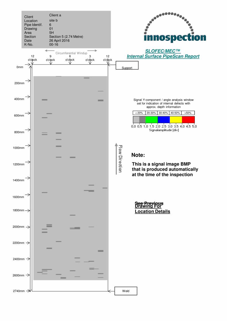
5 2740 No Significant Indications 0 - 20%
Below 20% wall loss - Grey 20-30% wall loss - Green 31-40% wall loss - Blue 41-50% wall loss - Yellow Above 50% wall loss - Red
OPS132 – Rev. 4 © 2016 Innospection Ltd
Client a SLOFEC™ LS120 Pipe Inspection Page 11 of 13
6” pipeline Final Report K00x-16xx
6 2800 No Significant Indications 0 - 20%
7 5300 No Significant Indications 0 - 20%
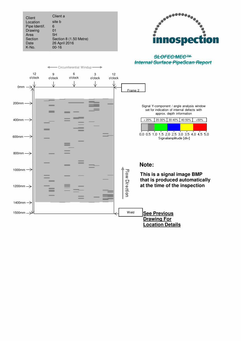
8 1500 No Significant Indications 0 - 20%
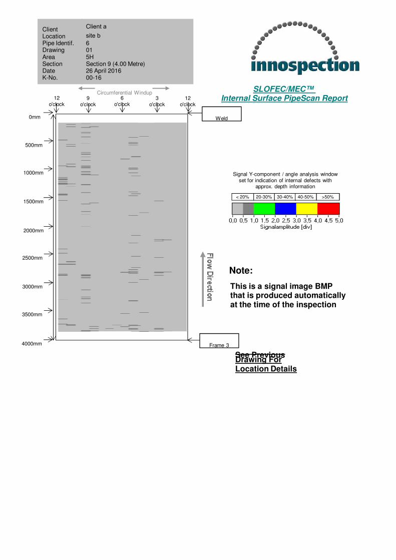
9 4000 No Significant Indications 0 - 20%
12 2500 No Significant Indications 0 - 20%
13 2500 No Significant Indications 0 - 20%
14 2000 No Significant Indications 0 - 20%
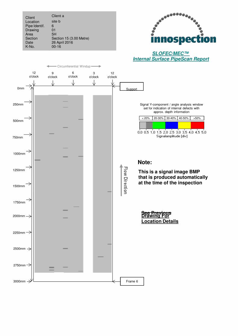
15 3000 No Significant Indications 0 - 20%
16 2000 No Significant Indications 0 - 20%
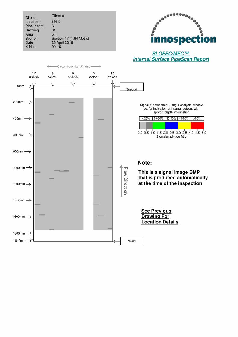
17 1840 No Significant Indications 0 - 20%
18 1000 No Significant Indications 0 - 20%
19 1100 No Significant Indications 0 - 20%
20 2000 No Significant Indications 0 - 20%
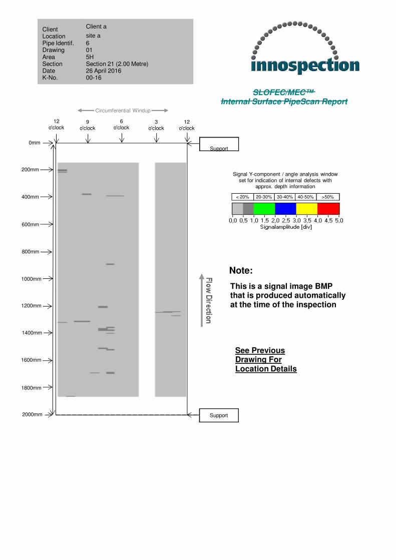
21 2000 No Significant Indications 0 - 20%
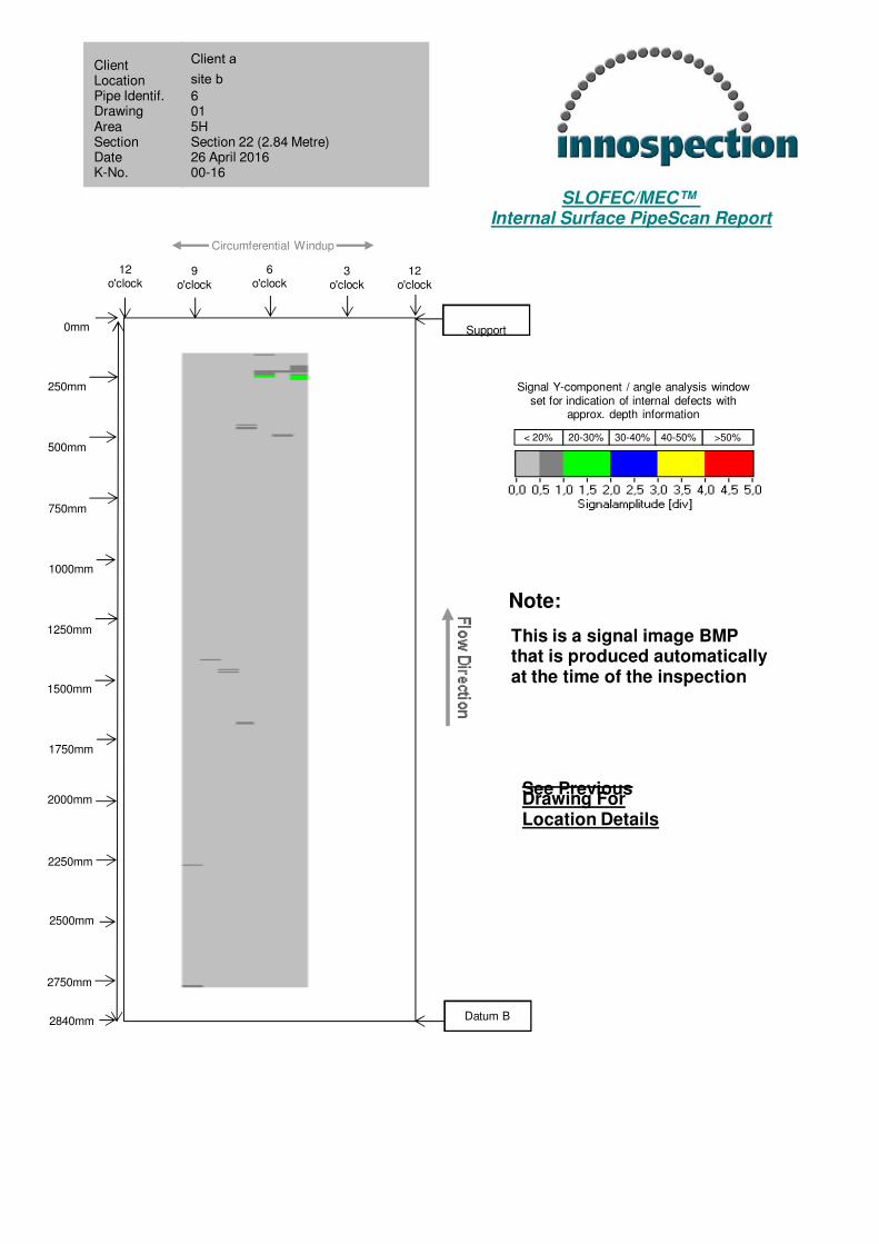
22 2500 No Significant Indications 20 - 30%
23 2500 No Significant Indications 0 - 20%
24 1200 No Significant Indications 0 - 20%
25 3200 No Significant Indications 0 - 20%
26 3500 No Significant Indications 0 - 20%
27 3500 No Significant Indications 0 - 20%
29 2000 No Significant Indications 0 - 20%
30 2000 No Significant Indications 0 - 20%
31 4000 No Significant Indications 0 - 20%
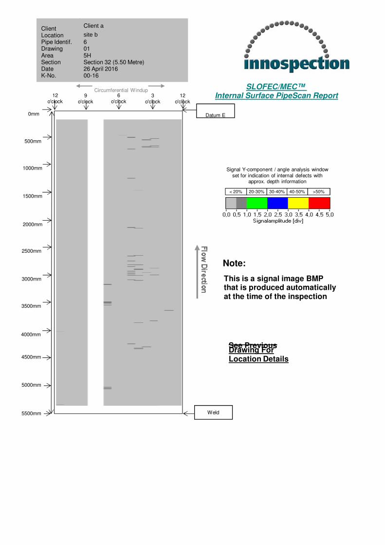
32 5500 No Significant Indications 0 - 20%
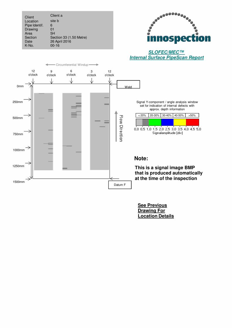
33 1500 No Significant Indications 0 - 20%
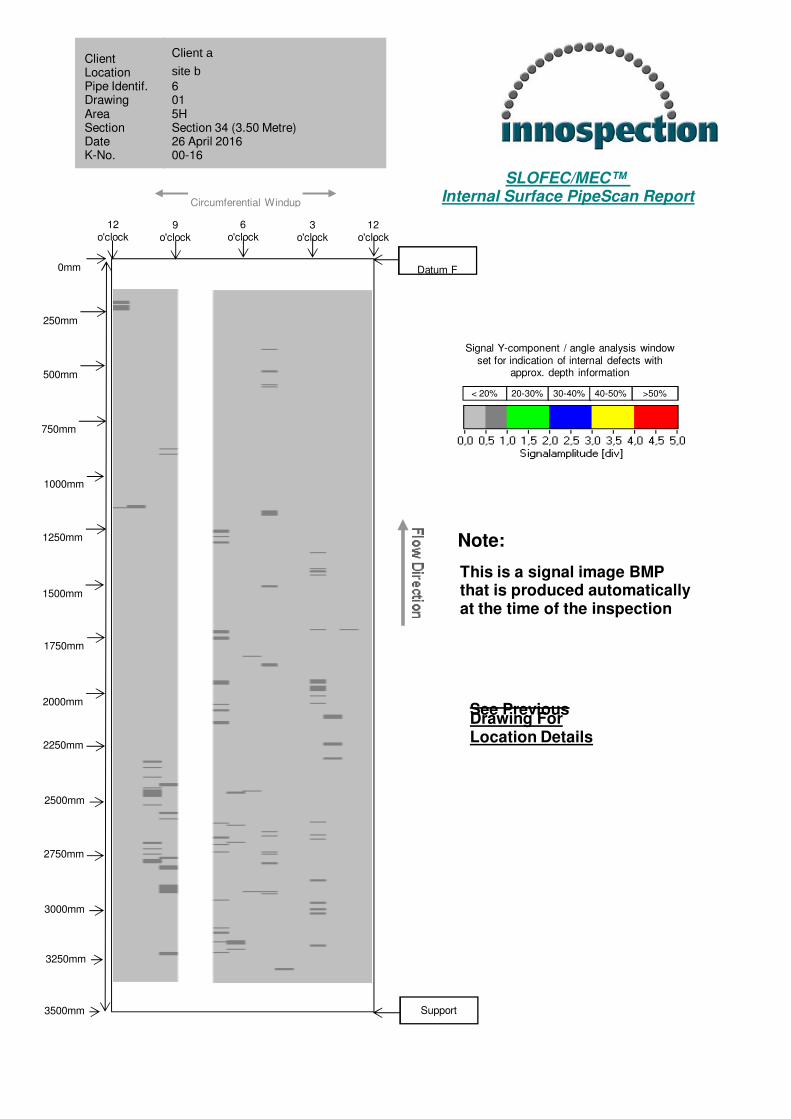
34 3500 No Significant Indications 0 - 20%
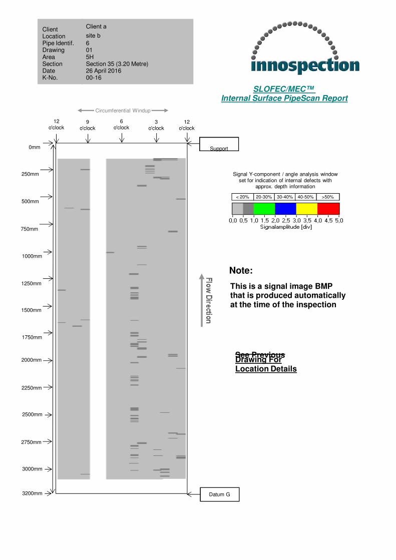
35 3200 No Significant Indications 0 - 20%
36 3300 No Significant Indications 0 - 20%
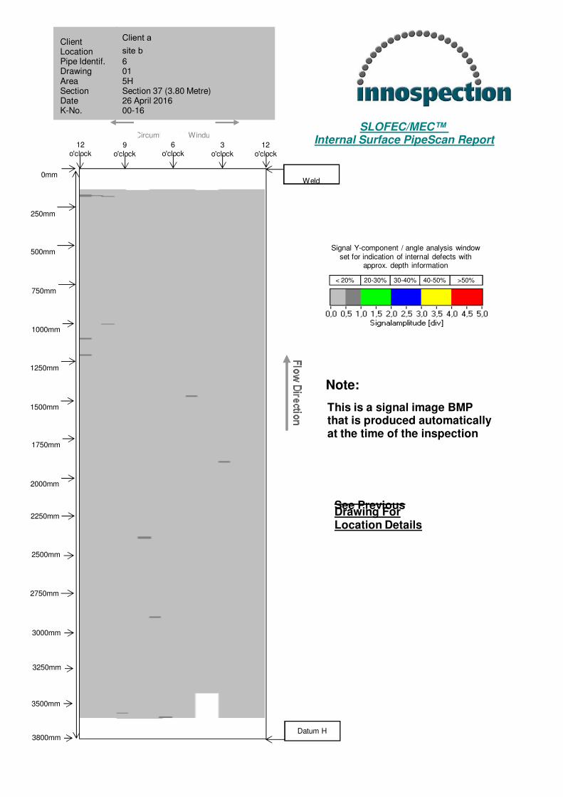
37 3800 No Significant Indications 0 - 20%
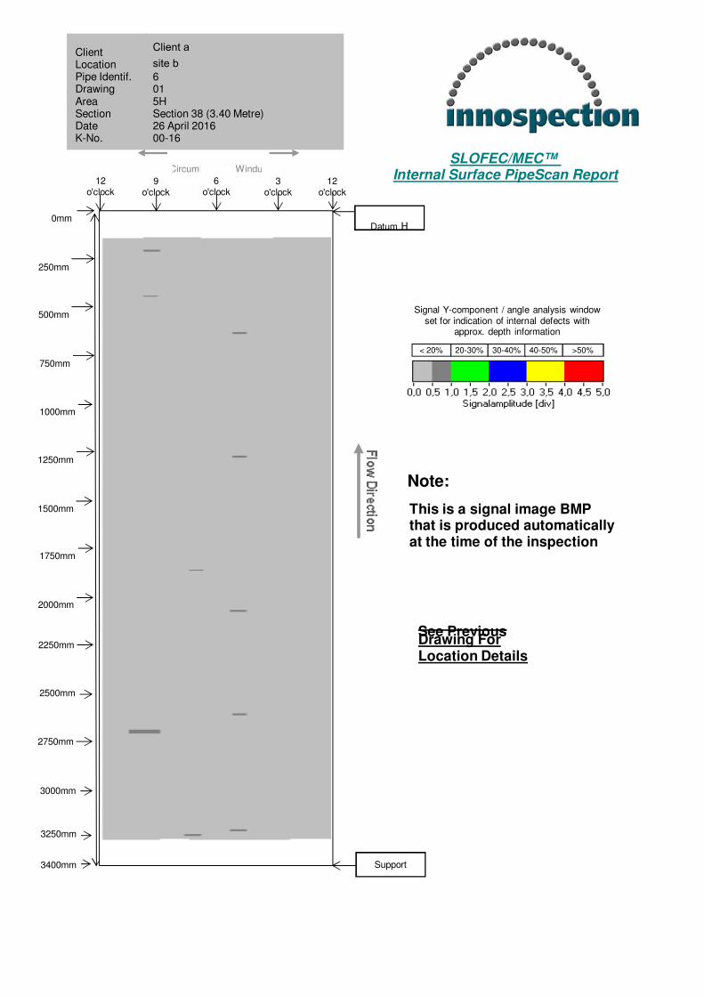
38 3800 No Significant Indications 0 - 20%
39 3600 No Significant Indications 0 - 20%
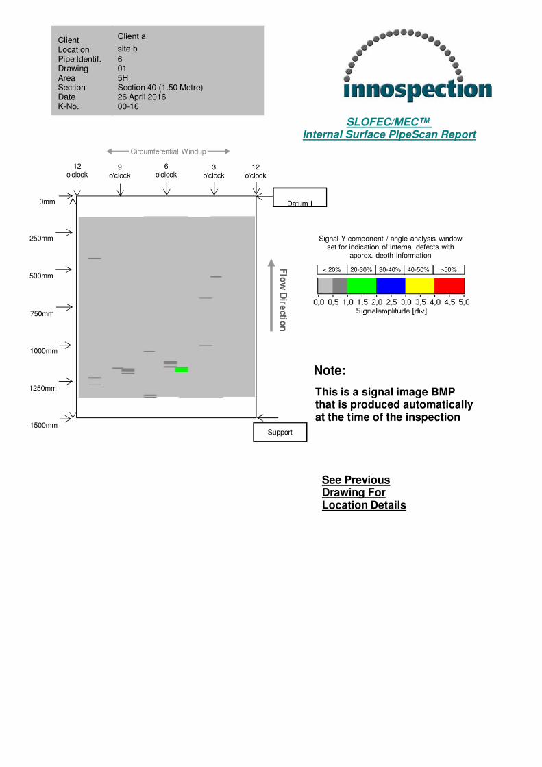
40 2500 No Significant Indications 20 - 30%
41 2000 No Significant Indications 0 - 20%
42 3000 No Significant Indications 0 - 20%
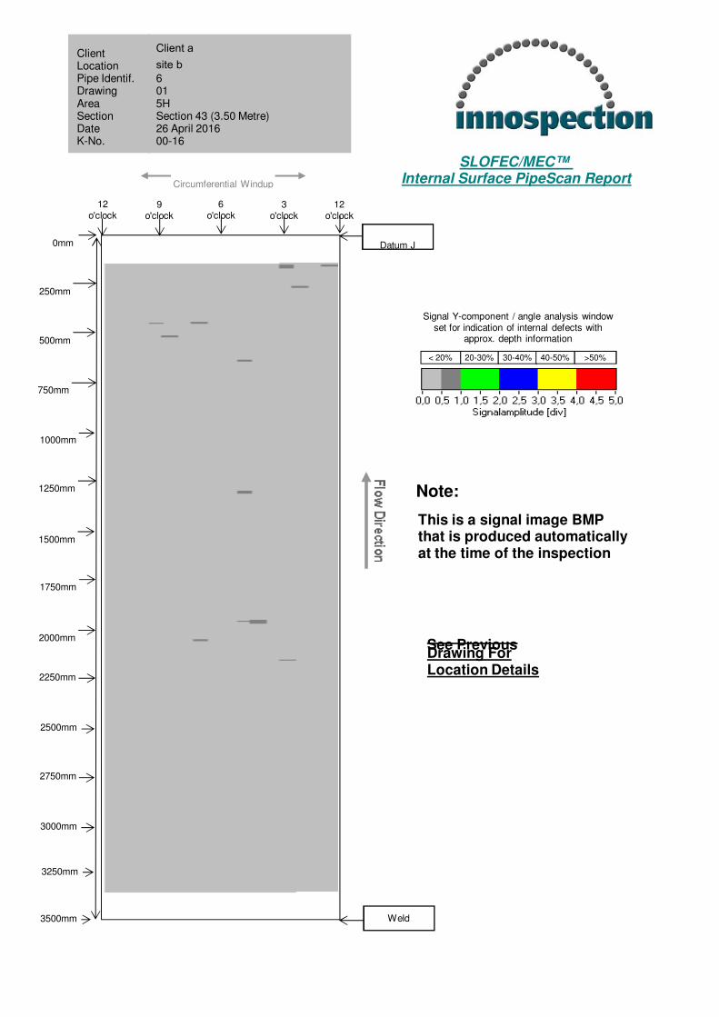
43 3500 No Significant Indications 0 - 20%
44 3600 No Significant Indications 0 - 20%
45 3300 No Significant Indications 0 - 20%
OPS132 – Rev. 4 © 2016 Innospection Ltd
Client a SLOFEC™ LS120 Pipe Inspection Page 12 of 13
6” pipeline Final Report K00x-16xx
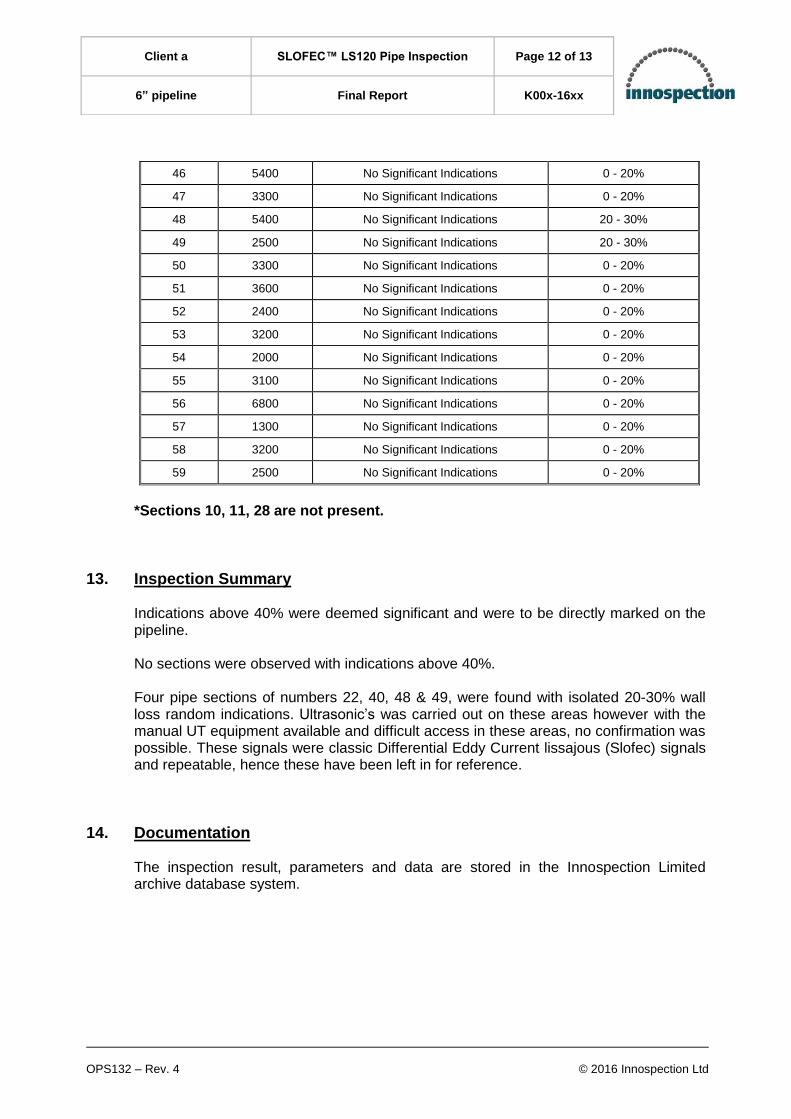
46 5400 No Significant Indications 0 - 20%
47 3300 No Significant Indications 0 - 20%
48 5400 No Significant Indications 20 - 30%
49 2500 No Significant Indications 20 - 30%
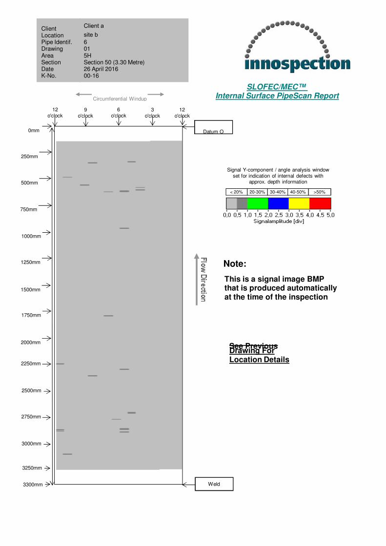
50 3300 No Significant Indications 0 - 20%
51 3600 No Significant Indications 0 - 20%
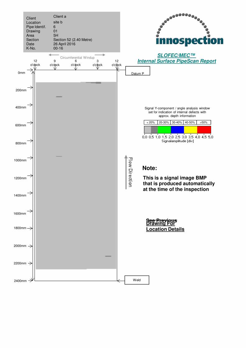
52 2400 No Significant Indications 0 - 20%
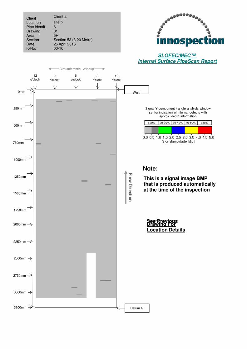
53 3200 No Significant Indications 0 - 20%
54 2000 No Significant Indications 0 - 20%
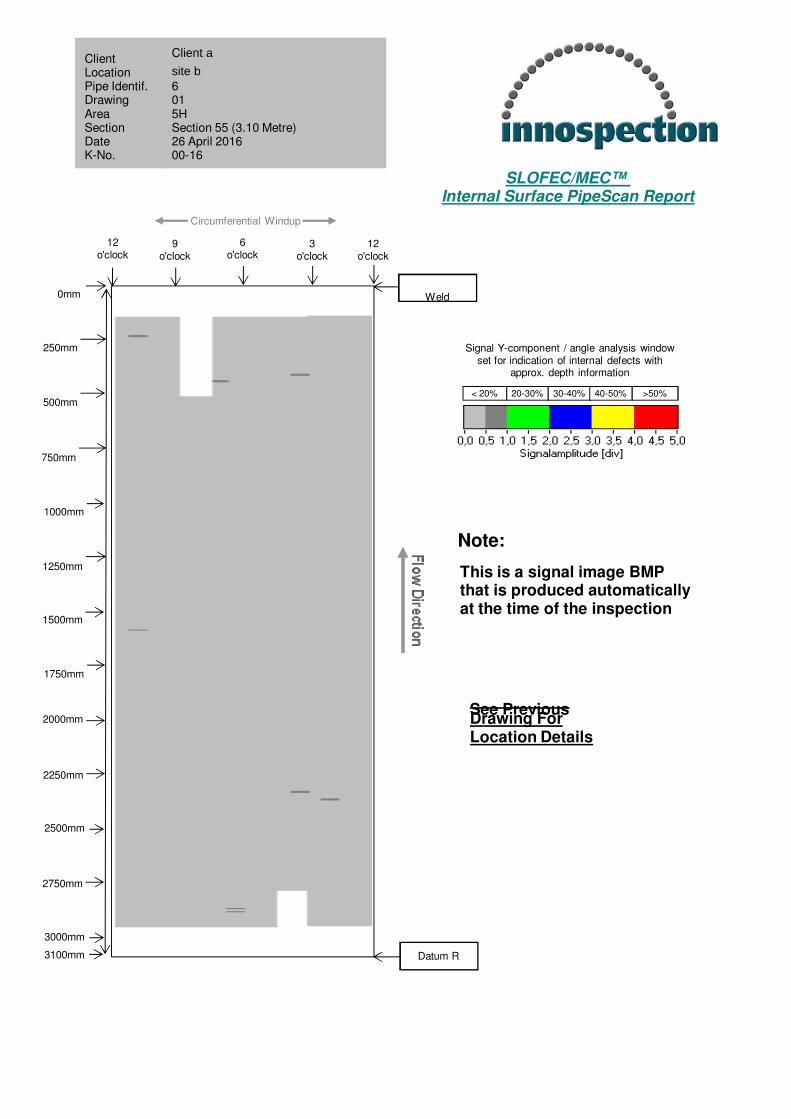
55 3100 No Significant Indications 0 - 20%
56 6800 No Significant Indications 0 - 20%
57 1300 No Significant Indications 0 - 20%
58 3200 No Significant Indications 0 - 20%
59 2500 No Significant Indications 0 - 20%
*Sections 10, 11, 28 are not present.
13. Inspection Summary
Indications above 40% were deemed significant and were to be directly marked on the pipeline. No sections were observed with indications above 40%. Four pipe sections of numbers 22, 40, 48 & 49, were found with isolated 20-30% wall loss random indications. Ultrasonic’s was carried out on these areas however with the manual UT equipment available and difficult access in these areas, no confirmation was possible. These signals were classic Differential Eddy Current lissajous (Slofec) signals and repeatable, hence these have been left in for reference.
14. Documentation The inspection result, parameters and data are stored in the Innospection Limited archive database system.
OPS132 – Rev. 4 © 2016 Innospection Ltd
Client a SLOFEC™ LS120 Pipe Inspection Page 13 of 13
6” pipeline Final Report K00x-16xx
15. Signature Technician a ET/UT Level 2 Innospection Limited Level 3 Senior Engineer PCN 00000 Innospection Limited

APPENDIX 01
Scanned Sections 1-59

12o'clock
Circumferential Windup
6o'clock
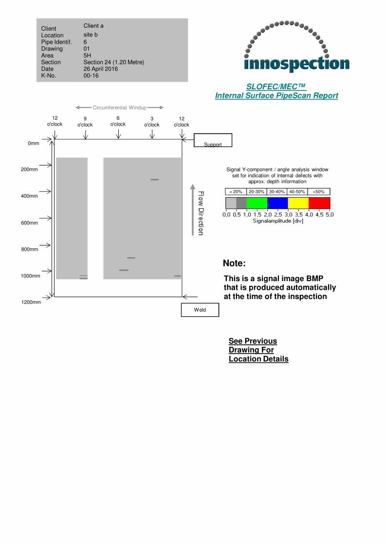
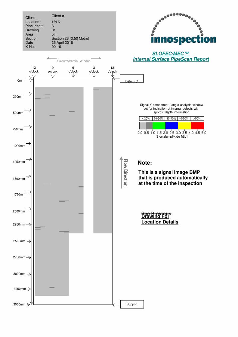
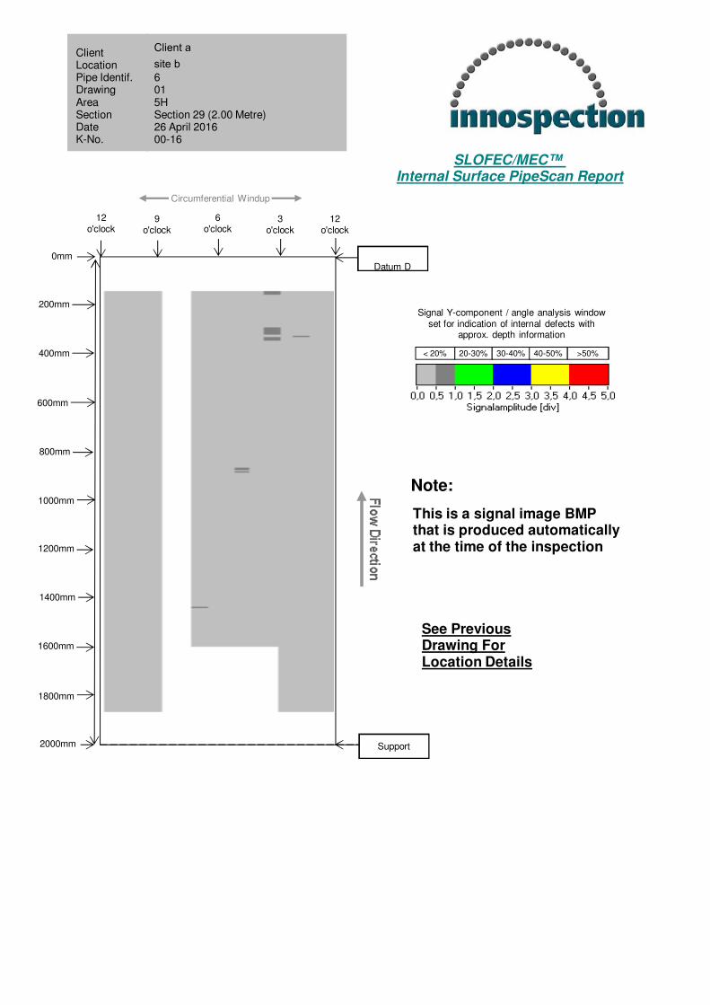
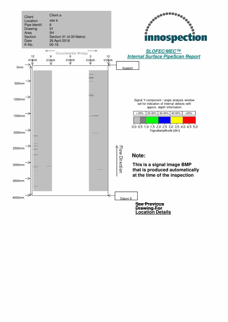
< 20% 20-30% 30-40% 40-50% >50%
Signal Y-component / angle analysis window set for indication of internal defects with
approx. depth information
:::::::
Note:
This is a signal image BMPthat is produced automaticallyat the time of the inspection
12o'clock
9o'clock
3o'clock
Client a
Site b
6 Pipeline
015Section 1 (2.00 Metre)26 April 201600-16
ClientLocationPipe Identif. Drawing Area SectionDate K-No.
400mm
800mm
1200mm
1600mm
2000mm
See Previous Drawing ForLocation Details
0mm
200mm
600mm
1000mm
1400mm
1800mm
Weld
Support
SLOFEC/MEC™ Internal Surface PipeScan Report

12o'clock
Circumferential Windup
6o'clock
< 20% 20-30% 30-40% 40-50% >50%
Signal Y-component / angle analysis window set for indication of internal defects with
approx. depth information
SLOFEC/MEC™ Internal Surface PipeScan Report
:::::::
Note:
This is a signal image BMPthat is produced automaticallyat the time of the inspection
12o'clock
9o'clock
3o'clock
Client a
site b
6 pipline
015Section 2 (2.00 Metre)26 April 201600-16
ClientLocationPipe Identif. Drawing Area SectionDate K-No.
400mm
800mm
1200mm
1600mm
2000mm
See Previous Drawing ForLocation Details
0mm
200mm
600mm
1000mm
1400mm
1800mm
Weld
Support
12o'clock
Circumferential Windup
6o'clock
< 20% 20-30% 30-40% 40-50% >50%
Signal Y-component / angle analysis window set for indication of internal defects with
approx. depth information
SLOFEC/MEC™ Internal Surface PipeScan Report
:::::::
Note:
This is a signal image BMPthat is produced automaticallyat the time of the inspection
12o'clock
9o'clock
3o'clock
Client a
site b
6" pipeline
015HSection 3 (2.00 Metre)26 April 201600-16
ClientLocationPipe Identif. Drawing Area SectionDate K-No.
400mm
800mm
1200mm
1600mm
2000mm
See Previous Drawing ForLocation Details
0mm
200mm
600mm
1000mm
1400mm
1800mm
Weld
Support

12o'clock
Circumferential Windup
6o'clock
< 20% 20-30% 30-40% 40-50% >50%
Signal Y-component / angle analysis window set for indication of internal defects with
approx. depth information
SLOFEC/MEC™ Internal Surface PipeScan Report
:::::::
Note:
This is a signal image BMPthat is produced automaticallyat the time of the inspection
12o'clock
9o'clock
3o'clock
Client a
site b
6" pipeline
01
5HSection 4 (2.00 Metre)26 April 201600-16
ClientLocationPipe Identif. Drawing Area SectionDate K-No.
400mm
800mm
1200mm
1600mm
2000mm
See Previous Drawing ForLocation Details
0mm
200mm
600mm
1000mm
1400mm
1800mm
Support
Support
< 20% 20-30% 30-40% 40-50% >50%
Signal Y-component / angle analysis window set for indication of internal defects with
approx. depth information
SLOFEC/MEC™ Internal Surface PipeScan Report
:::::::
Note:
This is a signal image BMPthat is produced automaticallyat the time of the inspection
Client a
site b
6 015HSection 5 (2.74 Metre)26 April 201600-16
ClientLocationPipe Identif. Drawing Area SectionDate K-No.
See Previous Drawing ForLocation Details
400mm
800mm
1200mm
1600mm
2000mm
200mm
600mm
1000mm
1400mm
1800mm
12o'clock
6o'clock
12o'clock
9o'clock
3o'clock
0mm
Weld
Support
2200mm
2400mm
2600mm
2740mm
Circumferential Windup

< 20% 20-30% 30-40% 40-50% >50%
Signal Y-component / angle analysis window set for indication of internal defects with
approx. depth information
SLOFEC/MEC™ Internal Surface PipeScan Report
:::::::
Note:
This is a signal image BMPthat is produced automaticallyat the time of the inspection
Client asite b6 015HSection 6 (2.80 Metre)26 April 201600-16
ClientLocationPipe Identif. Drawing Area SectionDate K-No.
See Previous Drawing ForLocation Details
400mm
800mm
1200mm
1600mm
2000mm
200mm
600mm
1000mm
1400mm
1800mm
12o'clock
6o'clock
12o'clock
9o'clock
3o'clock
0mm
Frame 1
Weld
2200mm
2400mm
2600mm
2800mm
Circumferential Windup

< 20% 20-30% 30-40% 40-50% >50%
Signal Y-component / angle analysis window set for indication of internal defects with
approx. depth information
SLOFEC/MEC™ Internal Surface PipeScan Report
:::::::
Note:
This is a signal image BMPthat is produced automaticallyat the time of the inspection
Client asite b6 015HSection 7 (5.30 Metre)26 April 201600-16
ClientLocationPipe Identif. Drawing Area SectionDate K-No.
See Previous Drawing ForLocation Details
1000mm
2000mm
3000mm
4000mm
5000mm
500mm
1500mm
2500mm
3500mm
4500mm
12o'clock
6o'clock
12o'clock
9o'clock
3o'clock
0mm
Frame 2
Frame 1
5300mm
Circumferential Windup
12o'clock
Circumferential Windup
6o'clock
< 20% 20-30% 30-40% 40-50% >50%
Signal Y-component / angle analysis window set for indication of internal defects with
approx. depth information
:::::::
Note:
This is a signal image BMPthat is produced automaticallyat the time of the inspection
12o'clock
9o'clock
3o'clock
Client asite b6 015HSection 8 (1.50 Metre)26 April 201600-16
ClientLocationPipe Identif. Drawing Area SectionDate K-No.
400mm
800mm
1200mm
1500mm See Previous Drawing ForLocation Details
0mm
200mm
600mm
1000mm
1400mm
Weld
Frame 2
SLOFEC/MEC™ Internal Surface PipeScan Report
< 20% 20-30% 30-40% 40-50% >50%
Signal Y-component / angle analysis window set for indication of internal defects with
approx. depth information
SLOFEC/MEC™ Internal Surface PipeScan Report
:::::::
Note:
This is a signal image BMPthat is produced automaticallyat the time of the inspection
Client asite b6 015HSection 9 (4.00 Metre)26 April 201600-16
ClientLocationPipe Identif. Drawing Area SectionDate K-No.
See Previous Drawing ForLocation Details
1000mm
2000mm
3000mm
4000mm
500mm
1500mm
2500mm
3500mm
12o'clock
6o'clock
12o'clock
9o'clock
3o'clock
0mm
Frame 3
Weld
Circumferential Windup

< 20% 20-30% 30-40% 40-50% >50%
Signal Y-component / angle analysis window set for indication of internal defects with
approx. depth information
SLOFEC/MEC™ Internal Surface PipeScan Report
:::::::
Note:
This is a signal image BMPthat is produced automaticallyat the time of the inspection
Client asite b6 015HSection 12 (2.50 Metre)26 April 201600-16
ClientLocationPipe Identif. Drawing Area SectionDate K-No.
See Previous Drawing ForLocation Details
400mm
800mm
1200mm
1600mm
2000mm
200mm
600mm
1000mm
1400mm
1800mm
12o'clock
6o'clock
12o'clock
9o'clock
3o'clock
0mm
Weld
Frame 4
2200mm
2400mm
2500mm
Circumferential Windup

< 20% 20-30% 30-40% 40-50% >50%
Signal Y-component / angle analysis window set for indication of internal defects with
approx. depth information
SLOFEC/MEC™ Internal Surface PipeScan Report
:::::::
Note:
This is a signal image BMPthat is produced automaticallyat the time of the inspection
Client asite b6 015HSection 13 (2.50 Metre)26 April 201600-16
ClientLocationPipe Identif. Drawing Area SectionDate K-No.
See Previous Drawing ForLocation Details
400mm
800mm
1200mm
1600mm
2000mm
200mm
600mm
1000mm
1400mm
1800mm
12o'clock
6o'clock
12o'clock
9o'clock
3o'clock
0mm
Frame 5
Weld
2200mm
2400mm
2500mm
Circumferential Windup

12o'clock
Circumferential Windup
6o'clock
< 20% 20-30% 30-40% 40-50% >50%
Signal Y-component / angle analysis window set for indication of internal defects with
approx. depth information
SLOFEC/MEC™ Internal Surface PipeScan Report
:::::::
Note:
This is a signal image BMPthat is produced automaticallyat the time of the inspection
12o'clock
9o'clock
3o'clock
Client a
site b
6 015HSection 14 (2.00 Metre)26 April 201600-16
ClientLocationPipe Identif. Drawing Area SectionDate K-No.
400mm
800mm
1200mm
1600mm
2000mm
See Previous Drawing ForLocation Details
0mm
200mm
600mm
1000mm
1400mm
1800mm
Frame 5
Support
12o'clock
Circumferential Windup
6o'clock
< 20% 20-30% 30-40% 40-50% >50%
Signal Y-component / angle analysis window set for indication of internal defects with
approx. depth information
SLOFEC/MEC™ Internal Surface PipeScan Report
:::::::
Note:
This is a signal image BMPthat is produced automaticallyat the time of the inspection
12o'clock
9o'clock
3o'clock
Client a
site b
6 015HSection 15 (3.00 Metre)26 April 201600-16
ClientLocationPipe Identif. Drawing Area SectionDate K-No.
500mm
1000mm
1500mm
See Previous Drawing ForLocation Details
0mm
250mm
750mm
1250mm
1750mm
2000mm
2500mm
2250mm
Support
Frame 6 3000mm
2750mm

12o'clock
Circumferential Windup
6o'clock
< 20% 20-30% 30-40% 40-50% >50%
Signal Y-component / angle analysis window set for indication of internal defects with
approx. depth information
SLOFEC/MEC™ Internal Surface PipeScan Report
:::::::
Note:
This is a signal image BMPthat is produced automaticallyat the time of the inspection
12o'clock
9o'clock
3o'clock
Client asite b6 015HSection 16 (2.00 Metre)26 April 201600-16
ClientLocationPipe Identif. Drawing Area SectionDate K-No.
400mm
800mm
1200mm
1600mm
2000mm
See Previous Drawing ForLocation Details
0mm
200mm
600mm
1000mm
1400mm
1800mm
Frame 6
Support
12o'clock
Circumferential Windup
6o'clock
< 20% 20-30% 30-40% 40-50% >50%
Signal Y-component / angle analysis window set for indication of internal defects with
approx. depth information
SLOFEC/MEC™ Internal Surface PipeScan Report
:::::::
Note:
This is a signal image BMPthat is produced automaticallyat the time of the inspection
12o'clock
9o'clock
3o'clock
Client a
site b
6 015HSection 17 (1.84 Metre)26 April 201600-16
ClientLocationPipe Identif. Drawing Area SectionDate K-No.
400mm
800mm
1200mm
1600mm
1840mm
See Previous Drawing ForLocation Details
0mm
200mm
600mm
1000mm
1400mm
1800mm
Support
Weld

12o'clock
Circumferential Windup
6o'clock
< 20% 20-30% 30-40% 40-50% >50%
Signal Y-component / angle analysis window set for indication of internal defects with
approx. depth information
SLOFEC/MEC™ Internal Surface PipeScan Report
:::::::
Note:
This is a signal image BMPthat is produced automaticallyat the time of the inspection
12o'clock
9o'clock
3o'clock
Client a
site b
6 015HSection 18 (1.00 Metre)26 April 201600-16
ClientLocationPipe Identif. Drawing Area SectionDate K-No.
400mm
800mm
See Previous Drawing ForLocation Details
0mm
200mm
600mm
1000mm
Weld
Support

12o'clock
Circumferential Windup
6o'clock
< 20% 20-30% 30-40% 40-50% >50%
Signal Y-component / angle analysis window set for indication of internal defects with
approx. depth information
SLOFEC/MEC™ Internal Surface PipeScan Report
:::::::
Note:
This is a signal image BMPthat is produced automaticallyat the time of the inspection
12o'clock
9o'clock
3o'clock
Client a
site b
6015Section 19 (1.10 Metre)26 April 201600-16
ClientLocationPipe Identif. Drawing Area SectionDate K-No.
400mm
800mm
1100mm
See Previous Drawing ForLocation Details
0mm
200mm
600mm
1000mm
Support
Weld

12o'clock
Circumferential Windup
6o'clock
< 20% 20-30% 30-40% 40-50% >50%
Signal Y-component / angle analysis window set for indication of internal defects with
approx. depth information
:::::::
Note:
This is a signal image BMPthat is produced automaticallyat the time of the inspection
12o'clock
9o'clock
3o'clock
Client asite b6 015HSection 20 (2.00 Metre)26 April 201600-16
ClientLocationPipe Identif. Drawing Area SectionDate K-No.
400mm
800mm
1200mm
1600mm
2000mm
See Previous Drawing ForLocation Details
0mm
200mm
600mm
1000mm
1400mm
1800mm
Support
Datum A
SLOFEC/MEC™ Internal Surface PipeScan Report
12o'clock
Circumferential Windup
6o'clock
< 20% 20-30% 30-40% 40-50% >50%
Signal Y-component / angle analysis window set for indication of internal defects with
approx. depth information
:::::::
Note:
This is a signal image BMPthat is produced automaticallyat the time of the inspection
12o'clock
9o'clock
3o'clock
Client a
site a
6 015HSection 21 (2.00 Metre)26 April 201600-16
ClientLocationPipe Identif. Drawing Area SectionDate K-No.
400mm
800mm
1200mm
1600mm
2000mm
See Previous Drawing ForLocation Details
0mm
200mm
600mm
1000mm
1400mm
1800mm
Support
Support
SLOFEC/MEC™ Internal Surface PipeScan Report
12o'clock
Circumferential Windup
6o'clock
< 20% 20-30% 30-40% 40-50% >50%
Signal Y-component / angle analysis window set for indication of internal defects with
approx. depth information
SLOFEC/MEC™ Internal Surface PipeScan Report
:::::::
Note:
This is a signal image BMPthat is produced automaticallyat the time of the inspection
12o'clock
9o'clock
3o'clock
Client asite b6 015HSection 22 (2.84 Metre)26 April 201600-16
ClientLocationPipe Identif. Drawing Area SectionDate K-No.
500mm
1000mm
1500mm
See Previous Drawing ForLocation Details
0mm
250mm
750mm
1250mm
1750mm
2000mm
2500mm
2250mm
Support
Datum B2840mm
2750mm

< 20% 20-30% 30-40% 40-50% >50%
Signal Y-component / angle analysis window set for indication of internal defects with
approx. depth information
SLOFEC/MEC™ Internal Surface PipeScan Report
:::::::
Note:
This is a signal image BMPthat is produced automaticallyat the time of the inspection
Client asite b6 015HSection 23 (2.50 Metre)26 April 201600-16
ClientLocationPipe Identif. Drawing Area SectionDate K-No.
See Previous Drawing ForLocation Details
400mm
800mm
1200mm
1600mm
2000mm
200mm
600mm
1000mm
1400mm
1800mm
12o'clock
6o'clock
12o'clock
9o'clock
3o'clock
0mm
Support
Datum B
2200mm
2400mm
2500mm
Circumferential Windup
12o'clock
Circumferential Windup
6o'clock
< 20% 20-30% 30-40% 40-50% >50%
Signal Y-component / angle analysis window set for indication of internal defects with
approx. depth information
SLOFEC/MEC™ Internal Surface PipeScan Report
:::::::
Note:
This is a signal image BMPthat is produced automaticallyat the time of the inspection
12o'clock
9o'clock
3o'clock
Client asite b6 015HSection 24 (1.20 Metre)26 April 201600-16
ClientLocationPipe Identif. Drawing Area SectionDate K-No.
400mm
800mm
1200mm
See Previous Drawing ForLocation Details
0mm
200mm
600mm
1000mm
Support
Weld

12o'clock
Circumferential Windup
6o'clock
< 20% 20-30% 30-40% 40-50% >50%
Signal Y-component / angle analysis window set for indication of internal defects with
approx. depth information
SLOFEC/MEC™ Internal Surface PipeScan Report
:::::::
Note:
This is a signal image BMPthat is produced automaticallyat the time of the inspection
12o'clock
9o'clock
3o'clock
Client asite b6 015HSection 25 (3.20 Metre)26 April 201600-16
ClientLocationPipe Identif. Drawing Area SectionDate K-No.
500mm
1000mm
1500mm
See Previous Drawing ForLocation Details
0mm
250mm
750mm
1250mm
1750mm
2000mm
2500mm
2250mm
Weld
Datum C
3000mm
2750mm
3200mm
< 20% 20-30% 30-40% 40-50% >50%
Signal Y-component / angle analysis window set for indication of internal defects with
approx. depth information
SLOFEC/MEC™ Internal Surface PipeScan Report
:::::::
Note:
This is a signal image BMPthat is produced automaticallyat the time of the inspection
Client asite b6 015HSection 26 (3.50 Metre)26 April 201600-16
ClientLocationPipe Identif. Drawing Area SectionDate K-No.
500mm
1000mm
1500mm
See Previous Drawing ForLocation Details
250mm
750mm
1250mm
1750mm
2000mm
2500mm
2250mm
3000mm
2750mm
3250mm
12o'clock
Circumferential Windup
6o'clock
12o'clock
9o'clock
3o'clock
0mm Datum C
Support3500mm

< 20% 20-30% 30-40% 40-50% >50%
Signal Y-component / angle analysis window set for indication of internal defects with
approx. depth information
SLOFEC/MEC™ Internal Surface PipeScan Report
:::::::
Note:
This is a signal image BMPthat is produced automaticallyat the time of the inspection
Client asite b6 015HSection 27 (3.50 Metre)26 April 201600-16
ClientLocationPipe Identif. Drawing Area SectionDate K-No.
500mm
1000mm
1500mm
See Previous Drawing ForLocation Details
250mm
750mm
1250mm
1750mm
2000mm
2500mm
2250mm
3000mm
2750mm
3250mm
12o'clock
Circumferential Windup
6o'clock
12o'clock
9o'clock
3o'clock
0mm Support
Datum D3500mm
12o'clock
Circumferential Windup
6o'clock
< 20% 20-30% 30-40% 40-50% >50%
Signal Y-component / angle analysis window set for indication of internal defects with
approx. depth information
SLOFEC/MEC™ Internal Surface PipeScan Report
:::::::
Note:
This is a signal image BMPthat is produced automaticallyat the time of the inspection
12o'clock
9o'clock
3o'clock
Client asite b6 015HSection 29 (2.00 Metre)26 April 201600-16
ClientLocationPipe Identif. Drawing Area SectionDate K-No.
400mm
800mm
1200mm
1600mm
2000mm
See Previous Drawing ForLocation Details
0mm
200mm
600mm
1000mm
1400mm
1800mm
Datum D
Support

12o'clock
Circumferential Windup
6o'clock
< 20% 20-30% 30-40% 40-50% >50%
Signal Y-component / angle analysis window set for indication of internal defects with
approx. depth information
SLOFEC/MEC™ Internal Surface PipeScan Report
:::::::
Note:
This is a signal image BMPthat is produced automaticallyat the time of the inspection
12o'clock
9o'clock
3o'clock
Client asite b6 015HSection 30 (2.00 Metre)26 April 201600-16
ClientLocationPipe Identif. Drawing Area SectionDate K-No.
400mm
800mm
1200mm
1600mm
2000mm
See Previous Drawing ForLocation Details
0mm
200mm
600mm
1000mm
1400mm
1800mm
Support
Support
< 20% 20-30% 30-40% 40-50% >50%
Signal Y-component / angle analysis window set for indication of internal defects with
approx. depth information
SLOFEC/MEC™ Internal Surface PipeScan Report
:::::::
Note:
This is a signal image BMPthat is produced automaticallyat the time of the inspection
Client a
site b
6 015HSection 31 (4.00 Metre)26 April 201600-16
ClientLocationPipe Identif. Drawing Area SectionDate K-No.
See Previous Drawing ForLocation Details
1000mm
2000mm
3000mm
4000mm
500mm
1500mm
2500mm
3500mm
12o'clock
6o'clock
12o'clock
9o'clock
3o'clock
0mm
Datum E
Support
Circumferential Windup
< 20% 20-30% 30-40% 40-50% >50%
Signal Y-component / angle analysis window set for indication of internal defects with
approx. depth information
SLOFEC/MEC™ Internal Surface PipeScan Report
:::::::
Note:
This is a signal image BMPthat is produced automaticallyat the time of the inspection
Client a
site b
6 015HSection 32 (5.50 Metre)26 April 201600-16
ClientLocationPipe Identif. Drawing Area SectionDate K-No.
See Previous Drawing ForLocation Details
1000mm
2000mm
3000mm
4000mm
5000mm
500mm
1500mm
2500mm
3500mm
4500mm
12o'clock
6o'clock
12o'clock
9o'clock
3o'clock
0mm
Weld
Datum E
5500mm
Circumferential Windup
12o'clock
Circumferential Windup
6o'clock
< 20% 20-30% 30-40% 40-50% >50%
Signal Y-component / angle analysis window set for indication of internal defects with
approx. depth information
SLOFEC/MEC™ Internal Surface PipeScan Report
:::::::
Note:
This is a signal image BMPthat is produced automaticallyat the time of the inspection
12o'clock
9o'clock
3o'clock
Client a
site b
6 015HSection 33 (1.50 Metre)26 April 201600-16
ClientLocationPipe Identif. Drawing Area SectionDate K-No.
500mm
1000mm
1500mm
See Previous Drawing ForLocation Details
0mm
250mm
750mm
1250mm
Weld
Datum F
< 20% 20-30% 30-40% 40-50% >50%
Signal Y-component / angle analysis window set for indication of internal defects with
approx. depth information
SLOFEC/MEC™ Internal Surface PipeScan Report
:::::::
Note:
This is a signal image BMPthat is produced automaticallyat the time of the inspection
Client a
site b
6 015HSection 34 (3.50 Metre)26 April 201600-16
ClientLocationPipe Identif. Drawing Area SectionDate K-No.
500mm
1000mm
1500mm
See Previous Drawing ForLocation Details
250mm
750mm
1250mm
1750mm
2000mm
2500mm
2250mm
3000mm
2750mm
3250mm
12o'clock
Circumferential Windup
6o'clock
12o'clock
9o'clock
3o'clock
0mm Datum F
Support3500mm
12o'clock
Circumferential Windup
6o'clock
< 20% 20-30% 30-40% 40-50% >50%
Signal Y-component / angle analysis window set for indication of internal defects with
approx. depth information
SLOFEC/MEC™ Internal Surface PipeScan Report
:::::::
Note:
This is a signal image BMPthat is produced automaticallyat the time of the inspection
12o'clock
9o'clock
3o'clock
Client asite b6 015HSection 35 (3.20 Metre)26 April 201600-16
ClientLocationPipe Identif. Drawing Area SectionDate K-No.
500mm
1000mm
1500mm
See Previous Drawing ForLocation Details
0mm
250mm
750mm
1250mm
1750mm
2000mm
2500mm
2250mm
Support
Datum G
3000mm
2750mm
3200mm

< 20% 20-30% 30-40% 40-50% >50%
Signal Y-component / angle analysis window set for indication of internal defects with
approx. depth information
SLOFEC/MEC™ Internal Surface PipeScan Report
:::::::
Note:
This is a signal image BMPthat is produced automaticallyat the time of the inspection
Client asite b6 015HSection 36 (3.30 Metre)26 April 201600-16
ClientLocationPipe Identif. Drawing Area SectionDate K-No.
500mm
1000mm
1500mm
See Previous Drawing ForLocation Details
250mm
750mm
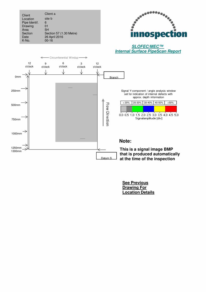
1250mm
1750mm
2000mm
2500mm
2250mm
3000mm
2750mm
3250mm
12o'clock
Circumferential Windup
6o'clock
12o'clock
9o'clock
3o'clock
0mm Datum G
Weld3300mm
< 20% 20-30% 30-40% 40-50% >50%
Signal Y-component / angle analysis window set for indication of internal defects with
approx. depth information
SLOFEC/MEC™ Internal Surface PipeScan Report
:::::::
Note:
This is a signal image BMPthat is produced automaticallyat the time of the inspection
Client asite b6 015HSection 37 (3.80 Metre)26 April 201600-16
ClientLocationPipe Identif. Drawing Area SectionDate K-No.
500mm
1500mm
See Previous Drawing ForLocation Details
250mm
1250mm
2000mm
2500mm
2250mm
3000mm
2750mm
750mm
1000mm
1750mm
3250mm
12o'clock
Circumferential Windup
6o'clock
12o'clock
9o'clock
3o'clock
0mm
3500mm
3800mmDatum H
Weld
< 20% 20-30% 30-40% 40-50% >50%
Signal Y-component / angle analysis window set for indication of internal defects with
approx. depth information
SLOFEC/MEC™ Internal Surface PipeScan Report
:::::::
Note:
This is a signal image BMPthat is produced automaticallyat the time of the inspection
Client asite b6 015HSection 38 (3.40 Metre)26 April 201600-16
ClientLocationPipe Identif. Drawing Area SectionDate K-No.
500mm
1500mm
See Previous Drawing ForLocation Details
250mm
1250mm
2000mm
2500mm
2250mm
3000mm
2750mm
750mm
1000mm
1750mm
3250mm
12o'clock
Circumferential Windup
6o'clock
12o'clock
9o'clock
3o'clock
0mm
3400mm Support
Datum H

< 20% 20-30% 30-40% 40-50% >50%
Signal Y-component / angle analysis window set for indication of internal defects with
approx. depth information
SLOFEC/MEC™ Internal Surface PipeScan Report
:::::::
Note:
This is a signal image BMPthat is produced automaticallyat the time of the inspection
Client asite b6 015HSection 39 (3.60 Metre)26 April 201600-16
ClientLocationPipe Identif. Drawing Area SectionDate K-No.
500mm
1500mm
See Previous Drawing ForLocation Details
250mm
1250mm
2000mm
2500mm
2250mm
3000mm
2750mm
750mm
1000mm
1750mm
3250mm
12o'clock
Circumferential Windup
6o'clock
12o'clock
9o'clock
3o'clock
0mm
3500mm
3600mm Datum I
Support
12o'clock
Circumferential Windup
6o'clock
< 20% 20-30% 30-40% 40-50% >50%
Signal Y-component / angle analysis window set for indication of internal defects with
approx. depth information
SLOFEC/MEC™ Internal Surface PipeScan Report
:::::::
Note:
This is a signal image BMPthat is produced automaticallyat the time of the inspection
12o'clock
9o'clock
3o'clock
Client asite b6 015HSection 40 (1.50 Metre)26 April 201600-16
ClientLocationPipe Identif. Drawing Area SectionDate K-No.
500mm
1000mm
1500mm
See Previous Drawing ForLocation Details
0mm
250mm
750mm
1250mm
Datum I
Support

12o'clock
Circumferential Windup
6o'clock
< 20% 20-30% 30-40% 40-50% >50%
Signal Y-component / angle analysis window set for indication of internal defects with
approx. depth information
SLOFEC/MEC™ Internal Surface PipeScan Report
:::::::
Note:
This is a signal image BMPthat is produced automaticallyat the time of the inspection
12o'clock
9o'clock
3o'clock
Client asite b6 05HSection 41 (2.00 Metre)26 April 201600-16
ClientLocationPipe Identif. Drawing Area SectionDate K-No.
400mm
800mm
1200mm
1600mm
2000mm
See Previous Drawing ForLocation Details
0mm
200mm
600mm
1000mm
1400mm
1800mm
Support
Support

12o'clock
Circumferential Windup
6o'clock
< 20% 20-30% 30-40% 40-50% >50%
Signal Y-component / angle analysis window set for indication of internal defects with
approx. depth information
SLOFEC/MEC™ Internal Surface PipeScan Report
:::::::
Note:
This is a signal image BMPthat is produced automaticallyat the time of the inspection
12o'clock
9o'clock
3o'clock
Client a
site b
6 015HSection 42 (3.00 Metre)26 April 201600-16
ClientLocationPipe Identif. Drawing Area SectionDate K-No.
500mm
1000mm
1500mm
See Previous Drawing ForLocation Details
0mm
250mm
750mm
1250mm
1750mm
2000mm
2500mm
2250mm
Support
Datum J3000mm
2750mm
< 20% 20-30% 30-40% 40-50% >50%
Signal Y-component / angle analysis window set for indication of internal defects with
approx. depth information
SLOFEC/MEC™ Internal Surface PipeScan Report
:::::::
Note:
This is a signal image BMPthat is produced automaticallyat the time of the inspection
Client asite b6 015HSection 43 (3.50 Metre)26 April 201600-16
ClientLocationPipe Identif. Drawing Area SectionDate K-No.
500mm
1000mm
1500mm
See Previous Drawing ForLocation Details
250mm
750mm
1250mm
1750mm
2000mm
2500mm
2250mm
3000mm
2750mm
3250mm
12o'clock
Circumferential Windup
6o'clock
12o'clock
9o'clock
3o'clock
0mm Datum J
Weld3500mm

< 20% 20-30% 30-40% 40-50% >50%
Signal Y-component / angle analysis window set for indication of internal defects with
approx. depth information
SLOFEC/MEC™ Internal Surface PipeScan Report
:::::::
Note:
This is a signal image BMPthat is produced automaticallyat the time of the inspection
Client asite b6 015HSection 44 (3.60 Metre)26 April 201600-16
ClientLocationPipe Identif. Drawing Area SectionDate K-No.
500mm
1500mm
See Previous Drawing ForLocation Details
250mm
1250mm
2000mm
2500mm
2250mm
3000mm
2750mm
750mm
1000mm
1750mm
3250mm
12o'clock
Circumferential Windup
6o'clock
12o'clock
9o'clock
3o'clock
0mm
3500mm
3600mm Datum K
Weld

< 20% 20-30% 30-40% 40-50% >50%
Signal Y-component / angle analysis window set for indication of internal defects with
approx. depth information
SLOFEC/MEC™ Internal Surface PipeScan Report
:::::::
Note:
This is a signal image BMPthat is produced automaticallyat the time of the inspection
Client a
site b
6 015HSection 45 (3.30 Metre)26 April 2016004-16
ClientLocationPipe Identif. Drawing Area SectionDate K-No.
500mm
1000mm
1500mm
See Previous Drawing ForLocation Details
250mm
750mm
1250mm
1750mm
2000mm
2500mm
2250mm
3000mm
2750mm
3250mm
12o'clock
Circumferential Windup
6o'clock
12o'clock
9o'clock
3o'clock
0mm Datum K
Datum L3300mm

< 20% 20-30% 30-40% 40-50% >50%
Signal Y-component / angle analysis window set for indication of internal defects with
approx. depth information
SLOFEC/MEC™ Internal Surface PipeScan Report
:::::::
Note:
This is a signal image BMPthat is produced automaticallyat the time of the inspection
Client a
site b
6 015HSection 46 (5.40 Metre)26 April 201600-16
ClientLocationPipe Identif. Drawing Area SectionDate K-No.
See Previous Drawing ForLocation Details
1000mm
2000mm
3000mm
4000mm
5000mm
500mm
1500mm
2500mm
3500mm
4500mm
12o'clock
6o'clock
12o'clock
9o'clock
3o'clock
0mm
Datum M
Datum L
5400mm
Circumferential Windup

< 20% 20-30% 30-40% 40-50% >50%
Signal Y-component / angle analysis window set for indication of internal defects with
approx. depth information
SLOFEC/MEC™ Internal Surface PipeScan Report
:::::::
Note:
This is a signal image BMPthat is produced automaticallyat the time of the inspection
Client a
site b
6 015HSection 47 (3.30 Metre)26 April 201600-16
ClientLocationPipe Identif. Drawing Area SectionDate K-No.
500mm
1000mm
1500mm
See Previous Drawing ForLocation Details
250mm
750mm
1250mm
1750mm
2000mm
2500mm
2250mm
3000mm
2750mm
3250mm
12o'clock
Circumferential Windup
6o'clock
12o'clock
9o'clock
3o'clock
0mm Datum M
Datum N3300mm

< 20% 20-30% 30-40% 40-50% >50%
Signal Y-component / angle analysis window set for indication of internal defects with
approx. depth information
SLOFEC/MEC™ Internal Surface PipeScan Report
:::::::
Note:
This is a signal image BMPthat is produced automaticallyat the time of the inspection
Client a
site b
6 015HSection 48 (5.40 Metre)26 April 201600-16
ClientLocationPipe Identif. Drawing Area SectionDate K-No.
See Previous Drawing ForLocation Details
1000mm
2000mm
3000mm
4000mm
5000mm
500mm
1500mm
2500mm
3500mm
4500mm
12o'clock
6o'clock
12o'clock
9o'clock
3o'clock
0mm
Weld
Datum N
5400mm
Circumferential Windup

< 20% 20-30% 30-40% 40-50% >50%
Signal Y-component / angle analysis window set for indication of internal defects with
approx. depth information
SLOFEC/MEC™ Internal Surface PipeScan Report
:::::::
Note:
This is a signal image BMPthat is produced automaticallyat the time of the inspection
Client asite b6 015HSection 49 (2.50 Metre)26 April 201600-16
ClientLocationPipe Identif. Drawing Area SectionDate K-No.
See Previous Drawing ForLocation Details
400mm
800mm
1200mm
1600mm
2000mm
200mm
600mm
1000mm
1400mm
1800mm
12o'clock
6o'clock
12o'clock
9o'clock
3o'clock
0mm
Datum O
Weld
2200mm
2400mm
2500mm
Circumferential Windup
< 20% 20-30% 30-40% 40-50% >50%
Signal Y-component / angle analysis window set for indication of internal defects with
approx. depth information
SLOFEC/MEC™ Internal Surface PipeScan Report
:::::::
Note:
This is a signal image BMPthat is produced automaticallyat the time of the inspection
Client asite b6 015HSection 50 (3.30 Metre)26 April 201600-16
ClientLocationPipe Identif. Drawing Area SectionDate K-No.
500mm
1000mm
1500mm
See Previous Drawing ForLocation Details
250mm
750mm
1250mm
1750mm
2000mm
2500mm
2250mm
3000mm
2750mm
3250mm
12o'clock
Circumferential Windup
6o'clock
12o'clock
9o'clock
3o'clock
0mm Datum O
Weld3300mm

< 20% 20-30% 30-40% 40-50% >50%
Signal Y-component / angle analysis window set for indication of internal defects with
approx. depth information
SLOFEC/MEC™ Internal Surface PipeScan Report
:::::::
Note:
This is a signal image BMPthat is produced automaticallyat the time of the inspection
Client asite b6 015HSection 51 (3.60 Metre)26 April 201600-16
ClientLocationPipe Identif. Drawing Area SectionDate K-No.
500mm
1500mm
See Previous Drawing ForLocation Details
250mm
1250mm
2000mm
2500mm
2250mm
3000mm
2750mm
750mm
1000mm
1750mm
3250mm
12o'clock
Circumferential Windup
6o'clock
12o'clock
9o'clock
3o'clock
0mm
3500mm
3600mm Datum P
Weld
< 20% 20-30% 30-40% 40-50% >50%
Signal Y-component / angle analysis window set for indication of internal defects with
approx. depth information
SLOFEC/MEC™ Internal Surface PipeScan Report
:::::::
Note:
This is a signal image BMPthat is produced automaticallyat the time of the inspection
Client asite b6 015HSection 52 (2.40 Metre)26 April 201600-16
ClientLocationPipe Identif. Drawing Area SectionDate K-No.
See Previous Drawing ForLocation Details
400mm
800mm
1200mm
1600mm
2000mm
200mm
600mm
1000mm
1400mm
1800mm
12o'clock
6o'clock
12o'clock
9o'clock
3o'clock
0mm
Weld
Datum P
2200mm
2400mm
Circumferential Windup
12o'clock
Circumferential Windup
6o'clock
< 20% 20-30% 30-40% 40-50% >50%
Signal Y-component / angle analysis window set for indication of internal defects with
approx. depth information
SLOFEC/MEC™ Internal Surface PipeScan Report
:::::::
Note:
This is a signal image BMPthat is produced automaticallyat the time of the inspection
12o'clock
9o'clock
3o'clock
Client a
site b
6 015HSection 53 (3.20 Metre)26 April 201600-16
ClientLocationPipe Identif. Drawing Area SectionDate K-No.
500mm
1000mm
1500mm
See Previous Drawing ForLocation Details
0mm
250mm
750mm
1250mm
1750mm
2000mm
2500mm
2250mm
Weld
Datum Q
3000mm
2750mm
3200mm

12o'clock
Circumferential Windup
6o'clock
< 20% 20-30% 30-40% 40-50% >50%
Signal Y-component / angle analysis window set for indication of internal defects with
approx. depth information
SLOFEC/MEC™ Internal Surface PipeScan Report
:::::::
Note:
This is a signal image BMPthat is produced automaticallyat the time of the inspection
12o'clock
9o'clock
3o'clock
Client a
site b
6 015HSection 54 (2.00 Metre)26 April 201600-16
ClientLocationPipe Identif. Drawing Area SectionDate K-No.
400mm
800mm
1200mm
1600mm
2000mm
See Previous Drawing ForLocation Details
0mm
200mm
600mm
1000mm
1400mm
1800mm
Datum Q
Weld
12o'clock
Circumferential Windup
6o'clock
< 20% 20-30% 30-40% 40-50% >50%
Signal Y-component / angle analysis window set for indication of internal defects with
approx. depth information
SLOFEC/MEC™ Internal Surface PipeScan Report
:::::::
Note:
This is a signal image BMPthat is produced automaticallyat the time of the inspection
12o'clock
9o'clock
3o'clock
Client a
site b
6 015HSection 55 (3.10 Metre)26 April 201600-16
ClientLocationPipe Identif. Drawing Area SectionDate K-No.
500mm
1000mm
1500mm
See Previous Drawing ForLocation Details
0mm
250mm
750mm
1250mm
1750mm
2000mm
2500mm
2250mm
Weld
Datum R
3000mm
2750mm
3100mm

< 20% 20-30% 30-40% 40-50% >50%
Signal Y-component / angle analysis window set for indication of internal defects with
approx. depth information
SLOFEC/MEC™ Internal Surface PipeScan Report
:::::::
Note:
This is a signal image BMPthat is produced automaticallyat the time of the inspection
Client a
site b
6 015HSection 56 (6.80 Metre)26 April 201600-16
ClientLocationPipe Identif. Drawing Area SectionDate K-No.
1000mm
2000mm
3000mm
See Previous Drawing ForLocation Details
500mm
1500mm
2500mm
3500mm
4000mm
5000mm
4500mm
6000mm
5500mm
6500mm
12o'clock
Circumferential Windup
6o'clock
12o'clock
9o'clock
3o'clock
0mm Datum R
Branch 6800mm
12o'clock
Circumferential Windup
6o'clock
< 20% 20-30% 30-40% 40-50% >50%
Signal Y-component / angle analysis window set for indication of internal defects with
approx. depth information
SLOFEC/MEC™ Internal Surface PipeScan Report
:::::::
Note:
This is a signal image BMPthat is produced automaticallyat the time of the inspection
12o'clock
9o'clock
3o'clock
Client a
site b
6 015HSection 57 (1.30 Metre)26 April 201600-16
ClientLocationPipe Identif. Drawing Area SectionDate K-No.
500mm
1000mm
1300mm
See Previous Drawing ForLocation Details
0mm
250mm
750mm
1250mm
Branch
Datum S
12o'clock
Circumferential Windup
6o'clock
< 20% 20-30% 30-40% 40-50% >50%
Signal Y-component / angle analysis window set for indication of internal defects with
approx. depth information
SLOFEC/MEC™ Internal Surface PipeScan Report
:::::::
Note:
This is a signal image BMPthat is produced automaticallyat the time of the inspection
12o'clock
9o'clock
3o'clock
Client a
site b
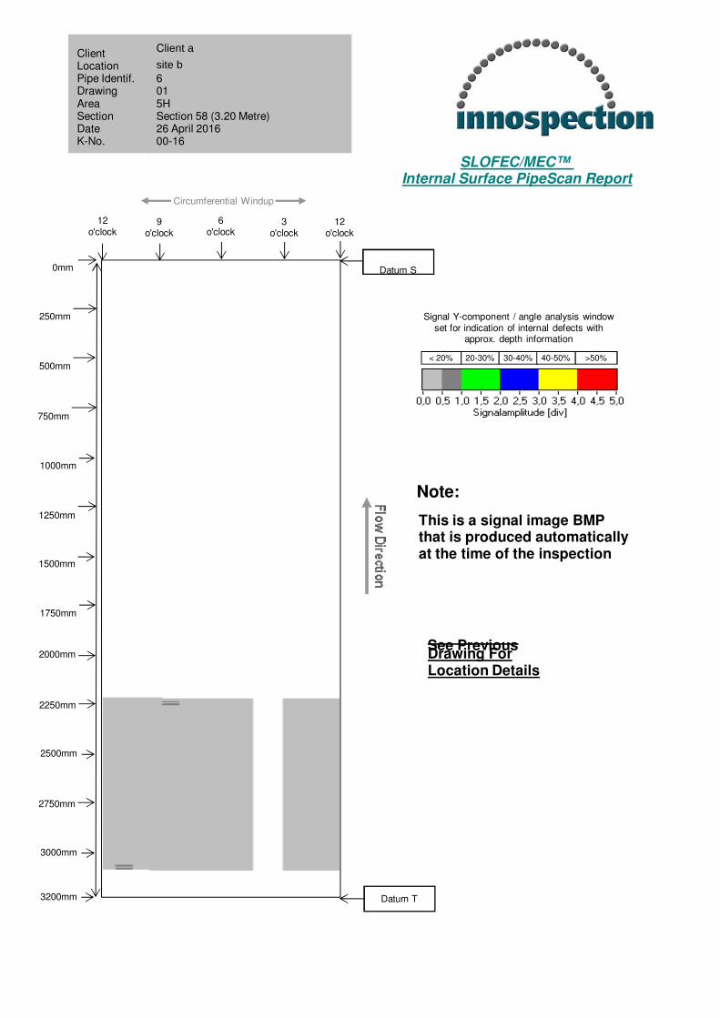
6 015HSection 58 (3.20 Metre)26 April 201600-16
ClientLocationPipe Identif. Drawing Area SectionDate K-No.
500mm
1000mm
1500mm
See Previous Drawing ForLocation Details
0mm
250mm
750mm
1250mm
1750mm
2000mm
2500mm
2250mm
Datum S
Datum T
3000mm
2750mm
3200mm

< 20% 20-30% 30-40% 40-50% >50%
Signal Y-component / angle analysis window set for indication of internal defects with
approx. depth information
SLOFEC/MEC™ Internal Surface PipeScan Report
:::::::
Note:
This is a signal image BMPthat is produced automaticallyat the time of the inspection
Client a
site b
6 015HSection 59 (2.50 Metre)26 April 201600-16
ClientLocationPipe Identif. Drawing Area SectionDate K-No.
See Previous Drawing ForLocation Details
400mm
800mm
1200mm
1600mm
2000mm
200mm
600mm
1000mm
1400mm
1800mm
12o'clock
6o'clock
12o'clock
9o'clock
3o'clock
0mm
Datum U
Datum T
2200mm
2400mm
2500mm
Circumferential Windup