SlipMeter™ - Rubicon Water€™s SlipMeter employs Sonaray ultrasonic array technology. The...
4
Transcript of SlipMeter™ - Rubicon Water€™s SlipMeter employs Sonaray ultrasonic array technology. The...

OverviewThe SlipMeter is a breakthrough all-in-one gate and meter for farmer service points and o�takes. Now it’s less labour intensive to provide irrigators with a reliable, �exible and accurate water delivery service.
You can remotely pre-set the SlipMeter to automatically deliver a constant and accurately measured �ow rate and volume. This means you can provide a great service day or night, even when supply channel levels are �uctuating.
And the all-in-one design means everything – drive system, motor control, ultrasonic measurement, power supply, local control keypad and telemetry – functions as a single unit. There are no installation problems or incompatibilities, it simply works.
The SlipMeter’s ability to measure accurately at high and very low �ow rates means it is suitable for all crop types. And the extremely low head loss means that command is not compromised even when very little head is available.
It has been designed to be installed in existing structures without costly civil work, by simply sliding into a frame that is �xed to the existing structure.
The built-in software provides the following control possibilities:
SlipMeter™
Control objective Gate action
Local Position Moves to a desired set-point and stays there
Flow Maintains a constant �ow regardless of channel levels
A TCC® productThe SlipMeter is one of the products making up a modular family of precision hardware and software called TCC (Total Channel Control®). TCC is an advanced technology set designed to improve the management and productivity of water in open channel and gravity pipeline distribution. Unlike traditional infrastructure, TCC products can interact and work together to help managers improve:
• the availability of water
• service and equity to users
• management and control
• health and safety for channel operators
Features• Independently veri�ed Sonaray® �ow measurement accuracy
of ±2.5%*
• Meets AS 4747 requirements
• Solar-charged battery system or mains power
• Robust high duty cycle operation and long life
• SCADA ready communication system – can be integrated to many SCADA platforms
An ideal solution for…
• Measuring and controlling �ow in farm service points
• Channel-to-pipe applications especially when large conduits are used
• Applications a�ected by turbulence
• Lowering civil costs because there is no need to stabilise �ow at entry and exit
• Service points requiring very low head loss and/or high accuracy
Data Sheet

Control pedestalEach SlipMeter installation includes a robust pedestal that provides power and control to the gate and is a secure, weather proof housing for electronic components and batteries.
The pedestal also serves as a local user interface. A keypad and LCD display are located under the lockable lid, allowing farmers to monitor, or operators to control and troubleshoot on-site.
High strength constructionThe gate panel is made from FormiPanel™, Rubicon’s high strength laminate construction method that uses techniques adopted from the aerospace and marine industries. Industrial adhesives are used to bond structural grade aluminium extrusions and skin plates to a synthetic core material. The result is strong, lightweight, and corrosion resistant.
Gate control technologyCableDrive™ is Rubicon’s actuation system designed to provide precision gate position accuracy and repeatability in harsh environments. The drive is a wire- rope (cable) and drum mechanism that provides positive drive in both the raise and lower directions. It is designed for high duty cycle operation and provides precise gate positioning to within ±0.5mm. The drive is managed by Rubicon’s SolarDrive® technology – a purpose built integrated circuit board that manages gate positioning, solar power regulation, battery charge, fusing and the pedestal user interface.
Low maintenanceThe SlipMeter’s modular design allows it to be maintained in the �eld with minimal tools, training, and easily replaceable parts.
• Does not require periodic recalibration to maintain accuracy
• Seals can be replaced
• On-site diagnostics built into the software
• Service can be done by local Rubicon �eld technicians or authorised/trained independent local integrators
Sonaray® �ow measurement technologyRubicon’s SlipMeter employs Sonaray ultrasonic array technology. The ultrasonic array principle maps the velocity pro�le by using multiple transecting paths to provide an accurate representation of the velocity distribution within the meter box.
This technique measures across the entire velocity �eld within the meter box and is resistant to swirl, or other non-uniform velocity distributions caused by garbage or other debris.
It also eliminates the need for �ow pro�le calibrations that are required for single-point, single-path and doppler �ow meters.
Control pedestal
Control Pedestal
1 Antenna2 Solar panel3 Hinged mast4 Secure controller housing
with LCD display
Meter/control unit
5 Entry �are
6 Sonaray sensors
7 Meter box
8 Gate seals
9 Internal frame (one side houses the ultrasonic level sensors)
10 Gate panel
11 Output drive assembly
12 Lifting hooks
13 Motor and encoder
14 Motor drive shaft
15 Planetary gear box
16 Encoder
17 Motor cover
18 CableDrive assembly
19 Cable drum
20 Cable guide
21 External frame
SlipMeter™ components
Data Sheet
SlipMeter™
Motor assembly detail
CableDrive detail
Control Pedestal
116
15
14
8
11
12
10
5
2
1713
18
3
7
6
10
20
21
19
4
Eight horizontal planes sample the velocity distribution passing through the meter (side view)
Each measurement plane implements crossed-path transit time ultrasonics to sample the entire velocity �eld in that plane (plan view of measurement plane)
The horizontal velocity distributions are then integrated vertically to construct the �ow velocity distribution (side view)
SolarDrive® electronics
Synthetic core
FormiPanel™ construction
Aluminium panel
Speci�cations subject to change
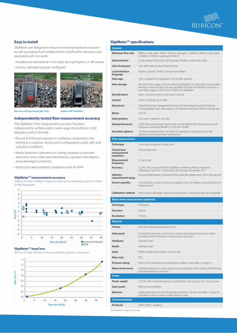
Easy to installSlipMeters are designed to mount to existing headwall structures as well as purpose built emplacements signi�cantly reducing costs associated with civil work.
• Installed and operational in two days during irrigation or o�-season
• Factory calibrated and pre-con�gured
Independently tested �ow measurement accuracy The SlipMeter’s �ow measurement accuracy has been independently veri�ed under a wide range of conditions in the laboratory and in the �eld.
• Provost & Pritchard engineers in California conducted in-situ testing in a customer service point con�guration under calm and turbulent conditions
• Manly Hydraulics Laboratory in Sydney, Australia conducted laboratory tests under wave disturbance, upstream disturbance and submerged conditions
• Testing has demonstrated compliance with AS 4747
SlipMeter™ speci�cationsGeneral
Minimum �ow rate 600mm wide gate: 1ML/d; 750mm wide gate: 1.56ML/d; 900mm wide gate: 2.25ML/d; 1200mm wide gate: 4ML/d
Data interface Local display (4 line LCD with keypad), Modbus serial, data radio
Unit of measure User de�nable (metric/imperial (US))
Local interface language
English, Spanish, French, Chinese and Italian
Data tags 140+ available for integration into SCADA systems
Data storage All volumetric usage is accumulated and backed up internally in nonvolatile memory. Historical data can be uploaded through the Modbus interface, a local data logger or from the SCADA host database.
Not full alarm Alarm indicates when meter box is not full
Control Local or remote via SCADA
Electronics SolarDrive® power management and control technology housed in the local control pedestal. Each unit passes a 12hr heat pre-stress and 100% functional test.
Motor 12V DC
Gate position 256 count magnetic encoder
Seal performance <0.02 litres/second per lineal metre of seal (better than the American and European standards AWWA C513 & DIN 19569)
Actuation options 12V DC powered (solar); 120-240V AC powered; mechanical override; electrical override pendant and battery
Flow measurement
Technique Cross-path ultrasonic transit-time
Transit time measurement resolution
100 picoseconds
Measurement frequency
2.5 seconds
Accuracy ±2.5% *Accuracy of 600mm SlipMeter veri�ed by Manly Hydraulics Laboratory, April 2011 and Provost & Pritchard, November 2011
Velocity \measurement range
Accuracy listed above is achieved at �ow velocities greater than 25mm per second
Sensor quantity 32 individual acoustic sensors, arranged in four cartridges, across 8 planes of measurement
Calibration method Factory pre-calibrated. Ultrasonic level sensor is also internally self-calibrated
Water level measurement (optional)
Technique Ultrasonic
Accuracy 0.5mm
Resolution 0.1mm
Material
Frames Extruded marine grade aluminium
Gate panel Composite laminate construction using marine grade aluminium sheet bonded to RTM Styrofoam on aluminium extrusion
Hardware Stainless steel
Shafts Stainless steel
Seals EDPM rubber (Durometer 70 (Shore A))
Wear strip PVC
Pressure rating Refer to the Dimensions and Maximum Water Level table on page 4
Water level sensor Anodized aluminium and copolymer acetyl plastic with stainless steel �ttings and gold-plated connectors
Power
Power supply 12V DC self-contained battery charged from solar panel or AC mains power
Solar panel 85W monocrystalline
Batteries Sealed gel lead acid with temperature sensor (~5yr life, provides ~5 days of operation without solar or mains power input)
Communications
Protocols DNP3, MDLC, Modbus
SlipMeter™ measurement accuracy (600mm 45° path SlipMeter measured under normal operating conditions relative to ABB Magmaster)
SlipMeter™ head loss 600mm 45° path SlipMeter measured at Manly Hydraulics Laboratory)
Remove existing manual gate and... replace with SlipMeter
.14
.12
.10
.08
.06
.04
.02
.000

Dimensions and maximum water levels
Mounting options
Front and side views
About Rubicon WaterRubicon Water delivers advanced technology that optimises gravity-fed irrigation, providing unprecedented levels of operational e�ciency and control, increasing water availability and improving farmers’ lives.
Founded in 1995, Rubicon have more than 20,000 gates installed in TCC systems in 10 countries.
A Gate size
B Maximum height of water above meter box �oor
C Frame width
D Overall gate height
E Box length
Model Weight A B C D E
kg mm mm mm mm mm
SMA-600-1500L 177 600 1500 862 2088 1208
SMA-600-1800L 187 600 1800 862 2415 1208
SMA-600-2400L 212 600 2400 862 3015 1208
SMA-600-3000L 222 600 3000 862 3615 1208
SMA-750-1800L 277 750 1800 1012 2465 1521
SMA-750-2400L 290 750 2400 1012 3065 1521
SMA-750-3000L 307 750 3000 1012 3665 1521
SMA-900-1800L 312 900 1800 1162 2565 1521
SMA-900-2400L 330 900 2400 1162 3065 1521
SMA-900-3000L 349 900 3000 1162 3665 1521
SMA-1050-2400L 412 1050 2400 1312 3165 1803
SMA-1050-3000L 432 1050 3000 1312 3665 1803
SMA-1200-2400L 452 1200 2400 1462 3165 1803
SMA-1200-3000L 472 1200 3000 1462 3665 1803
www.rubiconwater.com
© 2012-2017 Rubicon Water. RUBICON logo, CableDrive, FormiPanel, MicronLevel, SCADAConnect, SlipGate, SolarDrive, Total Channel Control and TCC are trademarks and service marks, or registered trademarks and service marks of Rubicon Water or its a�liates in Australia, the United States of America and other jurisdictions. Systems, components, methodologies and software supplied by Rubicon Water may be the subject of patent and design rights in Australia and elsewhere.
1 Cato Street Hawthorn East Victoria 3123 Australia
Tel: +61 3 9832 3000 Fax: +61 3 9832 3030 [email protected]
DS-
SM-0
5/17
-AU
Contact Rubicon for complete dimensions or additional sizes. Consultation with a Rubicon engineer or agent is recommended prior to gate sizing. Weights are approximate.
Headwall
Control box
Sidewalls
A
BD
C E