Slipform Paving Concrete Airfields Construction Techniquesto the bottom of the slipform pan should...
60
Slipform Paving Concrete Airfields – Construction Techniques Prepared by Ronald M. Guntert, CEO Guntert & Zimmerman Ripon, CA U.S.A.
Transcript of Slipform Paving Concrete Airfields Construction Techniquesto the bottom of the slipform pan should...
Slipform Paving
Concrete Airfields –
Construction TechniquesPrepared by
Ronald M. Guntert, CEO
Guntert & Zimmerman
Ripon, CA U.S.A.

Introduction
Concrete slipforming paving of thick airfield pavements
has been done successfully without forms for over 50
years.
Modern concrete paving equipment, with their built-in
features and options, have made this art easier.
The concrete itself is extremely critical to successful
concrete paving of thick airfield pavements


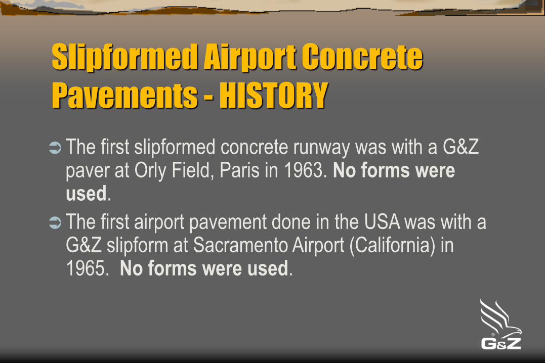
Slipformed Airport Concrete
Pavements - HISTORY
The first slipformed concrete runway was with a G&Z paver at Orly Field, Paris in 1963. No forms were used.
The first airport pavement done in the USA was with a G&Z slipform at Sacramento Airport (California) in 1965. No forms were used.

Slipformed Airport Concrete
Pavements - HISTORY
Concrete airport slabs have been successfully
slipformed up to 50' (15M) wide and 26" (660mm) thick.
The first slipformed concrete runway paved at 50'
(15M) wide was the Dallas-Fort Worth Airport in 1972.
The slab thickness was 21“ (533mm).


Bagram Air Force Base -Afghanistan


Slipformed Airport Concrete
Pavements
Historically the single biggest argument against
slipforming thick airport slabs was edge slump.
Since the first airport slab was slipformed, contractors
have learned methods and techniques to minimize, if
not avoid edge slump.
Concrete mix and uniformity play a big part in
successful thick slab airfield paving.

Highway Slab 34”
(857mm) Thick

Airport Slab LAX 30”
(762mm) Thick

Factors Contributing to High Quality
Slipformed Concrete Slabs
Concrete
Vibration
Sideforms / Edge Support
Edge Overbuild (thickened edge)
Flow of Concrete to the Edges
Concrete Finishing Devices
Concrete – Mix DesignWe are trying to achieve a mix design which will yield high quality, durable and workable concrete:
Finishes easily even at low slump
Vibration is transmitted easily achieving better consolidation
Smooth
No Edge slump
No joint or surface spalling

Well Graded Aggregate Mixtures

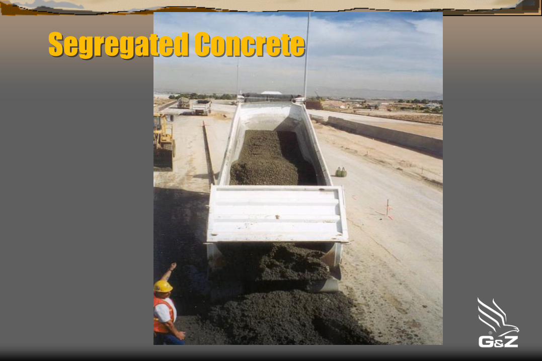
Segregation
“Segregation is caused by poor aggregate grading.
Where there are gaps in the gradation, horrible
segregation can occur at those sieve sizes.”
Shilstone

Segregated Concrete

Segregated Concrete
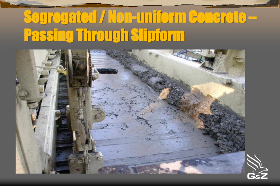
Segregated / Non-uniform Concrete –
Passing Through Slipform

Segregated / Non-uniform Concrete –
Passing Through Slipform

Segregated / Non-Uniform Concrete
Plan View
Slipform Pan

Segregated / Non-Uniform Concrete
Section View – Concrete Pile
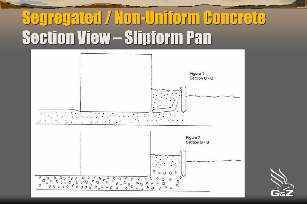
Segregated / Non-Uniform Concrete
Section View – Slipform Pan

Vibration
Only use well maintained vibrators which can maintain
a preset speed when under load and when the oil
warms up.
Proper placement of corner vibrator in liquification
hopper is vital. Proper location is 6" (15 cm) from the
sideform.
Adjust corner vibrator speed for best results. Corner
vibrators must be slowed down sometimes to avoid
pumping which can adversely impact edges.


Vibration
With most standard paving vibrators, vibrator speed
must be set between 8,000 and 9,500 vpm. New
heavier eccentric weight vibrators can be run at slower
speed to supply the same vibration energy.
Vibrator spacing on thicker airfield pavements is
typically an average center to center spacing of 14" (35
cm). On thinner airfield pavements 16" (40 cm) centers
on an average is the norm.
Vibration
Vibrator location (height) in the slab in the relationship
to the bottom of the slipform pan should be varied to
determine best results for a given mix. Depths from 0
to -6” (-15cm)have been used successfully.
New vibrator monitoring systems are available to help
paver operators monitor or automatically control and
maintain preset hydraulic poker vibrator speeds.

Sideforms
Sideforms must be supported top to bottom to assure a
rigid mold and sideforms plates must be straight and
not bent otherwise concrete edges will be adversely
affected.
Batter should be used sparingly to avoid acute angle
cracking of the adjacent slab. Some specifiers do not
allow any batter angle.

Sideforms
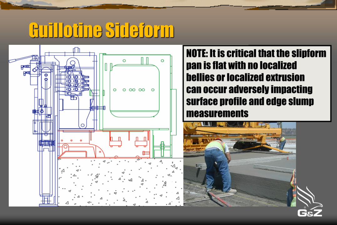
Guillotine SideformNOTE: It is critical that the slipform
pan is flat with no localized
bellies or localized extrusion
can occur adversely impacting
surface profile and edge slump
measurements

Sideforms
Do not extrude the edges from front to rear of the main
sideforms. Keep the attack angle of the pan flat. Only a
slight squeeze or no squeeze from front to rear of the
trailing finishing pan fixed edger pan sideform yields the
best results.
The less one touches the edge after slipforming the
better. The trailing finishing pan edger/sideforms can
help in finishing the edge better and more uniformly
than by hand finishing.

Sideforms
Most people have the misconception that when slipform
paving you are extruding. The secret to good edges is
not to extrude. If you extrude you pump or accelerate
concrete through the sideform which can cause edge
slump.
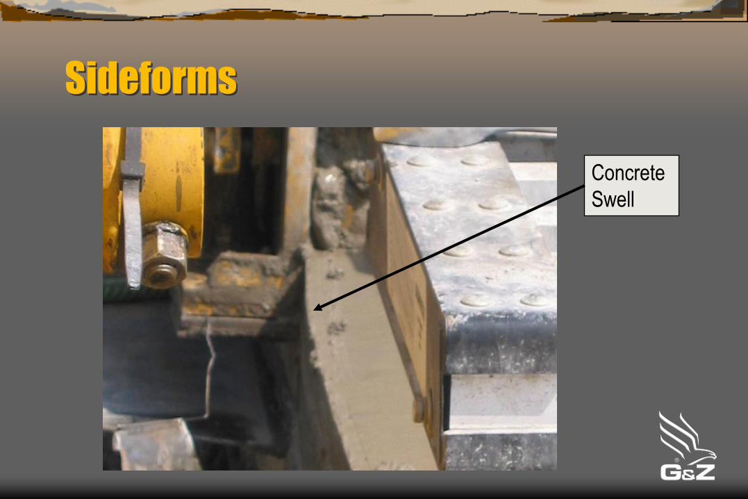
Sideforms
Concrete
Swell

Edge Overbuild
Modern slipform pavers today are equipped with edge overbuild devices on any finishing device that touches the concrete. Edge overbuilds thicken the concrete edge to help compensate for edge slump.
Edge overbuilds cannot compensate for varying concrete slump. Keep the concrete slump constant!
Don’t overbuild too much! The lower the concrete slump, the less overbuild. Typically the maximum is ¼" to ⅜“ (6 to 9mm.) The concrete mix will dictate how much overbuild.

Edge Overbuild

Flow of Concrete to the Edges
The end of the metering gate / strike-off should be far
enough away from the sideform to allow an
unobstructed flow of fresh concrete to fill the corner /
edge on thick slabs. This also allows a place for grout
build up in the corners to escape.


Flow of Concrete to the Edges
The paver operator must always:
Keep fresh concrete fed to the corners of the
liquification hopper (keep them full) to displace grout
and fill the edge.
Maintain a constant concrete head height over the top
of the vibrators using the metering gate.
Most operators prefer to keep a high head height on
thick slabs. Proper head management yields smoother
pavements.


Finishing Devices for Airfield Paving
There are three common paver mounted concrete finishing devices used on airfield paving. One or more of these devices can be used if the concrete mix / slab surface is harsh or difficult to finish:
Trailing Finishing Pan (TFP)
Final Finisher (FF) – Longitudinal Oscillating Ski
Oscillating Correcting Beam (OCB)

Finishing Devices for Airfield Paving
If a concrete mix needs excessive finishing, one
should look at doing something to improve
the mix design and aggregate gradations!

Finishing Devices for Airfield Paving
A Trailing Finishing Pan (TFP) is typically 4' (1.2m)
wide and floats on the concrete surface. The pan is
towed by the slipform’s paving kit. Most contractors
attach and tow layers of burlap behind the TFP.
On thicker slabs, where low slump, well graded
concrete is used, a Trailing Finishing Pan by itself
provides enough finishing; however, on hot and windy
days having a Final Finisher can be helpful especially
on wide paving such as 37.5 to 40’.

Trailing Finishing Pan

Final Finisher
On Standby
Trailing Finishing Pan

Finishing Devices for Airfield Paving
A Final Finisher is a device which includes a long,
narrow magnesium ski that floats on the concrete
surface. The ski oscillates fore and aft in the direction
of travel AND transversely back and forth across the
slab at the same time.

Final Finisher

Finishing Devices for Airfield Paving
An Oscillating Correcting Beam (OCB) can be an
effective means to finish low slump concrete but is
typically not used unless a Dowel Bar Inserter is used
to insert the dowels in the plastic concrete at the
location of the transverse contraction joints.

Oscillating
Correcting Beam
Oscillating Correcting Beam (OCB)

Mechanical Dowel Bar Inserters (DBI)
For nearly 30 years, mechanical Dowel Bar Inserters
(DBI) have been successfully used on thick airfield
pavements. Not all DBIs are alike!
Do a test section to demonstrate to the owner that the
DBI can insert the bars accurately and that
homogeneous concrete is sufficiently consolidated
around the bar.


New Fourth Runway at Dulles Airport,
Virginia USA – 2007

Hamad International Airport, Doha
Qatar – 2008

New Runway at Chicago-O’Hare
Airport, Illinois USA – 2015

Conclusion
Concrete
Vibration
Sideforms / Edge Support
Edge Overbuild (thickened edge)
Flow of Concrete to the Edges
Concrete Finishing Devices
All rights to reproduce any part of this presentation
are at the sole discretion of Guntert & Zimmerman
Const. Div., Inc.
For additional information contact the Administrative
Department at:
222 E. Fourth St. Ripon, CA 95366
Phone (209) 599-0066 Fax (209) 599-2021
Email [email protected] Web www.guntert.com


![Luftwaffe Airfields 1935-45 Austria (1937 Borders) - Austria [1937 Borders].pdf · Luftwaffe Airfields 1935-45 Airfields Austria (1937 borders) Introduction Preface The Germans marched](https://static.fdocuments.us/doc/165x107/5b67ba067f8b9a68538b8c0b/luftwaffe-airfields-1935-45-austria-1937-borders-austria-1937-borderspdf.jpg)