Slim Seam - Metal Roofing Source
13
Slim Seam ® Architectural Design Manual Headquarters: 3449 Hempland Road Lancaster, PA 17601 Phone: 800-477-2741 Fax: 800-283-4289 Architectural Products Division: 308 Alabama Blvd. Jackson, GA 30233 Phone: 800-884-4484 Fax: 800-765-4484
Transcript of Slim Seam - Metal Roofing Source

Slim Seam®
Architectural Design Manual
Headquarters: 3449 Hempland Road Lancaster, PA 17601 Phone: 800-477-2741 Fax: 800-283-4289
Architectural Products Division: 308 Alabama Blvd. Jackson, GA 30233 Phone: 800-884-4484 Fax: 800-765-4484
GENERAL INFORMATION
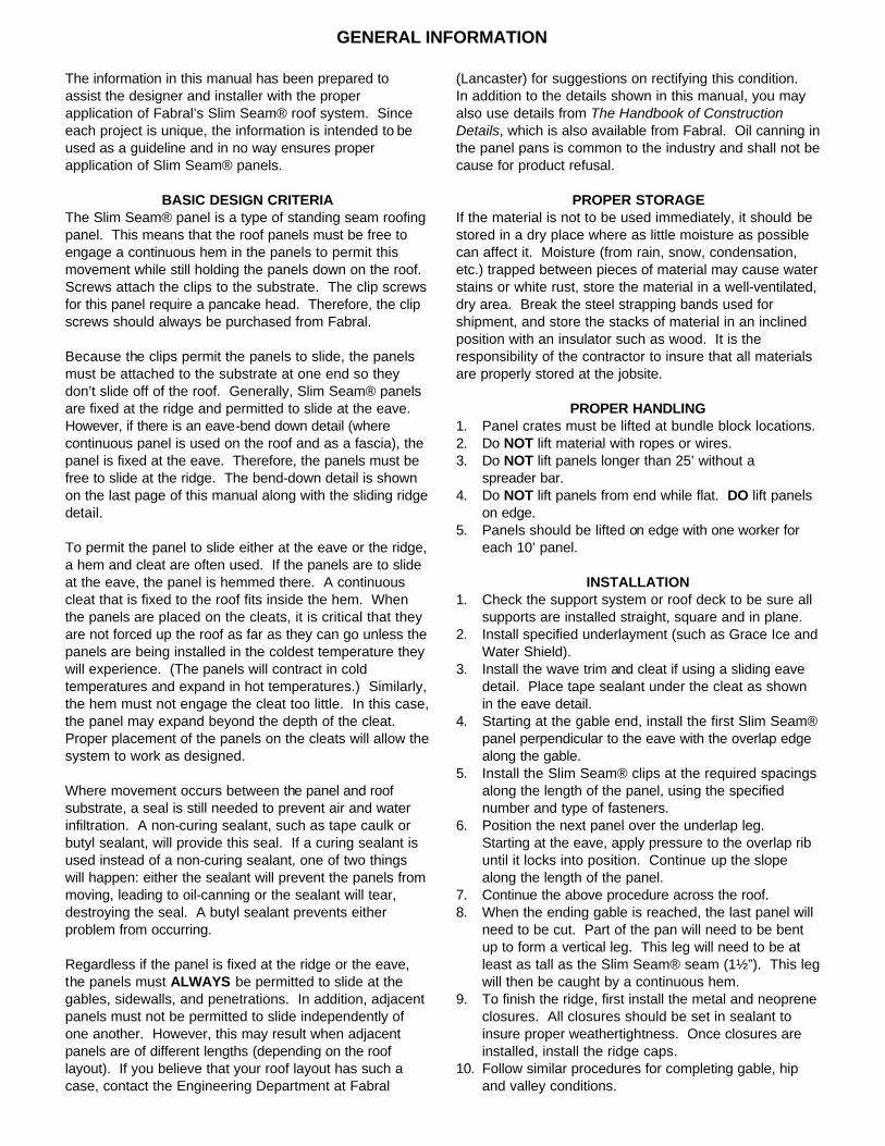
The information in this manual has been prepared to assist the designer and installer with the proper application of Fabral’s Slim Seam® roof system. Since each project is unique, the information is intended to be used as a guideline and in no way ensures proper application of Slim Seam® panels.
BASIC DESIGN CRITERIA The Slim Seam® panel is a type of standing seam roofing panel. This means that the roof panels must be free to engage a continuous hem in the panels to permit this movement while still holding the panels down on the roof. Screws attach the clips to the substrate. The clip screws for this panel require a pancake head. Therefore, the clip screws should always be purchased from Fabral. Because the clips permit the panels to slide, the panels must be attached to the substrate at one end so they don’t slide off of the roof. Generally, Slim Seam® panels are fixed at the ridge and permitted to slide at the eave. However, if there is an eave-bend down detail (where continuous panel is used on the roof and as a fascia), the panel is fixed at the eave. Therefore, the panels must be free to slide at the ridge. The bend-down detail is shown on the last page of this manual along with the sliding ridge detail. To permit the panel to slide either at the eave or the ridge, a hem and cleat are often used. If the panels are to slide at the eave, the panel is hemmed there. A continuous cleat that is fixed to the roof fits inside the hem. When the panels are placed on the cleats, it is critical that they are not forced up the roof as far as they can go unless the panels are being installed in the coldest temperature they will experience. (The panels will contract in cold temperatures and expand in hot temperatures.) Similarly, the hem must not engage the cleat too little. In this case, the panel may expand beyond the depth of the cleat. Proper placement of the panels on the cleats will allow the system to work as designed. Where movement occurs between the panel and roof substrate, a seal is still needed to prevent air and water infiltration. A non-curing sealant, such as tape caulk or butyl sealant, will provide this seal. If a curing sealant is used instead of a non-curing sealant, one of two things will happen: either the sealant will prevent the panels from moving, leading to oil-canning or the sealant will tear, destroying the seal. A butyl sealant prevents either problem from occurring. Regardless if the panel is fixed at the ridge or the eave, the panels must ALWAYS be permitted to slide at the gables, sidewalls, and penetrations. In addition, adjacent panels must not be permitted to slide independently of one another. However, this may result when adjacent panels are of different lengths (depending on the roof layout). If you believe that your roof layout has such a case, contact the Engineering Department at Fabral
(Lancaster) for suggestions on rectifying this condition. In addition to the details shown in this manual, you may also use details from The Handbook of Construction Details, which is also available from Fabral. Oil canning in the panel pans is common to the industry and shall not be cause for product refusal.
PROPER STORAGE If the material is not to be used immediately, it should be stored in a dry place where as little moisture as possible can affect it. Moisture (from rain, snow, condensation, etc.) trapped between pieces of material may cause water stains or white rust, store the material in a well-ventilated, dry area. Break the steel strapping bands used for shipment, and store the stacks of material in an inclined position with an insulator such as wood. It is the responsibility of the contractor to insure that all materials are properly stored at the jobsite.
PROPER HANDLING 1. Panel crates must be lifted at bundle block locations. 2. Do NOT lift material with ropes or wires. 3. Do NOT lift panels longer than 25’ without a
spreader bar. 4. Do NOT lift panels from end while flat. DO lift panels
on edge. 5. Panels should be lifted on edge with one worker for
each 10’ panel.
INSTALLATION 1. Check the support system or roof deck to be sure all
supports are installed straight, square and in plane. 2. Install specified underlayment (such as Grace Ice and
Water Shield). 3. Install the wave trim and cleat if using a sliding eave
detail. Place tape sealant under the cleat as shown in the eave detail.
4. Starting at the gable end, install the first Slim Seam® panel perpendicular to the eave with the overlap edge along the gable.
5. Install the Slim Seam® clips at the required spacings along the length of the panel, using the specified number and type of fasteners.
6. Position the next panel over the underlap leg. Starting at the eave, apply pressure to the overlap rib until it locks into position. Continue up the slope along the length of the panel.
7. Continue the above procedure across the roof. 8. When the ending gable is reached, the last panel will
need to be cut. Part of the pan will need to be bent up to form a vertical leg. This leg will need to be at least as tall as the Slim Seam® seam (1½”). This leg will then be caught by a continuous hem.
9. To finish the ridge, first install the metal and neoprene closures. All closures should be set in sealant to insure proper weathertightness. Once closures are installed, install the ridge caps.
10. Follow similar procedures for completing gable, hip and valley conditions.

11. Prior to the end of each workday, all panels should be adequately fastened to prevent any damage due to
wind uplift and/or thermal movement.

1.01 SUMMARY A. Section includes: Prefinished, prefabricated, snap-together, structural standing seam roof
system and accessories. B. Related Sections
1. Metal decking 2. Rough carpentry, plywood, and underlayment 3. Insulation 4. Membrane roofing 5. Flashing and sheet metal 6. Joint sealers: sealants and caulk 7. Structural framing.
1.02 REFERENCES A. American Society for Testing and Materials (ASTM)
1. ASTM A 653: Steel Sheet, Zinc-Coated by the Hot Dip Process 2. ASTM A 792: Steel Sheet, Aluminum-Zinc Alloy Coated by the Hot Dip Process. 3. ASTM B 209: Aluminum and Aluminum Alloy Sheet and Plate. 4. ASTM E 283: Air leakage 5. ASTM E 331: Water penetration 6. ASTM E 1646-95 Water Penetration 7. ASTM E 1680-95 Air Infiltration and Exfiltration
B. Underwriters Laboratory 1. UL Building Materials Directory 2. Underwriters Laboratories Construction No. 274, 274a, and 369 for Uplift Test 580
Class 90. C. Sheet Metal and Air Condition Contractors National Association, Inc. (SMACNA)
1. SMACNA Architectural Sheet Metal Manual, 1993 Edition. D. American Iron and Steel Institute (AISI)
1. AISI Cold Formed Steel Design Manual E. Aluminum Association
1. Aluminum Design Manual F. Metal Construction Association (MCA)
1. Preformed Metal Wall Guidelines G. Code references
1. ASCE, Minimum Loads for Buildings and Other Structures 2. BOCA National Building Code 3. UBC Uniform Building Code 4. SBC Standard Building Code
1.03 SYSTEM DESCRIPTION A. Performance Requirements: Provide factory formed, prefinished, snap-together, concealed
clip, structural standing seam metal roof system, that has been pretested and certified by manufacturer to comply with specified requirements under installed conditions. 1. Provide UL90 rated roofing system that has been tested in accordance with UL 580 test
procedure. Steel panels shall be capable of spanning 3'-0" o.c. purlins with UL90 rating.
2. Resistance to air leakage: there was no air infiltration at 20 psf pressure differential. There was 0.06 cfm/ft.2 air exfiltration at 20 psf pressure differential.
3. Resistance to water penetration: there was no leakage through panel joints when tested in accordance with ASTM E 1646 at static pressure differential of 12.0 psf.
B. Structural Requirements: Engineer panels for structural properties in accordance with latest edition of American Iron and Steel Institute Cold Formed Steel Design Manual using Aeffective width" concept and Aluminum Association=s Aluminum Design Manual.
C. Design loads for Slim Seam® panel system shall be as determined by the ASTM E 1592 wind uplift structural performance test.
1.04 SUBMITTALS A. Product Data: submit manufacturer's specifications, standard profile sheet, product data
brochure and finish warranty. B. Shop Drawings: shop drawings showing roof plan with layout of panels, clips, clip
attachment, underlayment and sections of each flashing/trim condition shall be submitted for approval prior to fabrication. Drawings shall contain material type, metal thickness and finish. Drawings shall distinguish between factory and field fabrication.
C. Samples: 1. Submit sample 12" long x full width panel, showing proposed metal gauge, seam profile
and specified finish. 2. Submit manufacturers standard colors for Architect's selection.
D. Test Reports: 1. Submit the test reports prepared by Underwriters Laboratory indicating wind uplift rating
of proposed roof system. The manufacturer must be listed by name in the UL Directory. 2. Air leakage per ASTM E 1680 and Water penetration per ASTM E 1646 (Actual
independent laboratory certified test results must be submitted). E. Certification: Submit manufacturer's certification that materials and finishes meet
specification requirements. 1.05 QUALITY ASSURANCE
A. Panel manufacturer shall have a minimum of ten (10) years of experience in manufacturing architectural roofing in a permanent stationary indoor facility.
B. Panel installer shall have a minimum of two (2) years experience in the installation of concealed clip architectural standing seam metal roofing and show evidence of successful completion of at least three (3) projects of similar size, scope, and complexity.
1.06 DELIVERY, STORAGE, and HANDLING A. Panels and flashings shall be protected and properly packaged to protect against
transportation damage in transit to the jobsite. B. Upon delivery, exercise care in unloading, stacking, moving, storing, and erecting panels
and flashings to prevent twisting, bending, scratching, or denting. C. Store panels and flashings in a safe, dry environment under a waterproof covering to prevent
water damage. Allow for adequate ventilation to prevent condensation. Panels and flashings with strippable film shall not be stored in direct sunlight.
D. Upon installation immediately remove strippable film from panels and flashings. Protect panels and flashings from foot traffic and from all other trades.
1.07 PROJECT CONDITIONS A. Field dimensions shall be taken prior to fabrication to verify jobsite conditions. B. Minimum recommended pitch for this panel is 1:12. C. Maximum panel length is 48' (contact the factory for longer panels).
1.08 WARRANTIES A. Panel manufacturer shall provide a twenty (20) year warranty on the paint finish covering
chalking, cracking, checking, chipping, blistering, peeling, flaking, and fading. B. Applicator shall furnish written warranty for a two (2) year period from date of substantial
completion of building covering repairs required to maintain roof and flashings in watertight conditions.
2.01 PRODUCT DESCRIPTION A. Slim Seam structural standing seam roof system as manufactured by Fabral, 3449
Hempland Road, Lancaster, PA 17601; ph.: 717-397-2741; fax: 717-397-1040. B. The Slim Seam panel shall have a coverage of 12" or 16". Seams shall be 12" high. C. Roof panels shall use a one-piece roof clip allowing for unlimited thermal movement of the
panel system. D. The panel shall have a factory applied mastic and be seamed by snapping together the
integral seam. E. The panel system shall be as a true standing seam shape requiring no trapezoidal foam
closures, plugs, or fillers at eaves. 2.02 PRODUCT SUBSTITUTIONS
A. Requests to use alternate systems shall be submitted in writing to the project designer at least ten (10) days prior to bid date. Request shall demonstrate proposed substitution meets or exceeds specified performance requirements. Certified statements, samples and descriptive data shall be included in this submittal request.
B. Manufacturers listed in this section are prequalified manufacturers. Substitution of manufacturer's products for those specified shall not be allowed at anytime during construction.
2.03 MATERIALS AND FINISHES A. Panel materials
1. 24 or 22 gauge, Grade 40 (40 ksi yield strength) structural steel with G90 (0.90 oz./ft.2) hot dipped galvanized coating, both conforming to ASTM A 653.
2. 24 or 22 ga., Grade 40 (40 ksi yield strength) structural steel with AZ50 (0.50 oz./ft.2) aluminum-zinc alloy coating, both conforming to ASTM A 792.
3. 0.032" or 0.040", 3105-H14 or equivalent (20 ksi yield strength) aluminum alloy conforming to ASTM B 209.
B. Texture: panels shall be smooth. C. Finish: Refer to manufacturer's standard color card to determine appropriate finish and
color. All panels shall receive a factory-applied Kynar7 500/Hylar7 5000* conform ing to the following: 1. Metal preparation: all metal shall have the surfaces carefully prepared for painting on a
continuous process coil coating line by alkali cleaning, hot water rinsing, application of
chemical conversion coating, cold water rinsing, sealing with an acid rinse, and thorough drying.
2. Prime coating: a base coat of polyester paint, specifically formulated to interact with the top-coat, shall be applied to the prepared surfaces by roll coating to a dry film thickness of 0.20 ∀ 0.05 mils. This prime coat shall be oven cured prior to application of finish coat.
3. Exterior coating: a Kynar7 500/Hylar7 5000 finish coating shall be applied over the primer by roll coating to a dry film thickness of 0.80 ∀ 0.05 mils for a total dry film thickness of 1.00 ∀ 0.10. This finish coating shall be oven-cured.
4. Interior coating: a washcoat shall be applied on the reverse side over the primer by roll coating to a dry film thickness of 0.30 ∀ 0.05 mils for a total dry film thickness of 0.50 ∀ 0.10 mils. The washcoat shall be oven-cured.
5. Color: the color of the exterior finish shall be _____ as chosen from the manufacturer's standard color chart.
6. Physical properties: the coating shall conform to the manufacturer's standard performance criteria as listed by certified test reports for fade, chalk, abrasion, humidity, adhesion, pollution resistance, and others as required and standard within the industry.
2.04 ACCESSORIES A. Concealed clips:
1. 1 pc.: 22 ga. stainless steel UL90 rated clip, 3" long. 2. 1 pc.: 24 ga. galvanized steel clip, 3" long.
B. Flashing and Trim 1. All flashing and trim shall be of the same material, gauge, finish, and color as the roof
panels and fabricated in accordance with standard SMACNA procedure and details. 2. Provide transition rib covers where roofing changes pitch. 3. Fabricate gutters and downspouts in the same gauge, material, finish, and color as the
roof panels. C. Fasteners
1. Clips to substrate: Screw shall be #10 diameter, self tapping type (for attachment to wood) or self-drilling, self tapping (for attachment to light gauge structurals), zinc-plated steel with a flat, phillips drive head.
2. Flashings to panels: exposed screws shall be zinc plated with a #14 x 1" combination steel and neoprene washer, color to match panel.
D. Sealants 1. Shall not contain oil, asbestos, or asphalt. 2. Factory applied sealant shall be applied in the seam and designed for metal to metal
concealed joints. 3. Field applied panel end sealant shall be mastic tape sealant. 4. Exposed sealant shall be one-part polyurethane joint sealant. Coordinate color with
roof panels. E. Closures
1. Ridge and hip closures shall be protected and supported by a formed metal closure manufactured from the same material, color, and finish as the panels.
2. Metal closures shall be factory fabricated and field-cut as needed. F. Vapor Retarder:
1. Retarder with a permeance of 0.05 or less as determined by ASTM E 98. 2.05 RELATED MATERIALS
A. Refer to other sections listed in Related Sections paragraph for related materials. 2.06 FABRICATION
A. Roof panels shall be formed in continuous lengths. End laps will not be allowed. B. Panels shall to be roll formed on a stationary industrial type rolling mill to gradually shape
the sheet metal. Portable rollformers, rented or owned by the installer, are not acceptable. C. Fabricate flashings from the same material as the roof system.
2.07 SOURCE QUALITY A. Source Quality: obtain metal panels and accessories from a single manufacturer. B. Fabrication tolerances: follow tolerances in MCA=s Preformed Metal Wall Guidelines. C. Tests and inspections D. Verification of performance
3.01 MANUFACTURER=S INSTRUCTIONS A. Compliance: Comply with manufacturer=s product data, including product technical
bulletins, product catalog installation instructions, and product cartons for installation. 3.02 EXAMINATION
A. Installer shall: 1. Inspect roof deck and/or purlins to verify that it complies with shop drawings and is
smooth, even, sound, and free of depressions. 2. Report variations and potential problems in writing to the architect.
3.03 INSTALLATION A. Conform to the standard set forth in the SMACNA architectural sheet metal manuals and
the approved shop drawings detailed for the project. B. Install panels plumb, level, and straight with the seams parallel, conforming to the design
as indicated. C. Install panel system so it is watertight, without waves, warps, buckles or distortions, and
allow for thermal movement considerations. D. Abrasive devices shall not be used to cut on or near roof panel system. E. Apply sealant tape or caulking as necessary at flashing and panel joints to prevent water
penetration. F. Remove any strippable film immediately upon exposure to direct sunlight. G. Vapor retarder: The joints, perimeter, and all openings shall be sealed per the
manufacturer's instructions to provide a continuous vapor retarder. H. Underlayment (solid substrate):
1. Provide one layer of 30# felt with horizontal overlaps and endlaps staggered between layers.
2. Provide ice and water shield membrane at all valley and eave conditions as well as any area at less than a 3:12 slope.
3. Lay parallel to ridge line with 22" horizontal laps and 6" vertical laps. 3.04 CLEANING
A. Dispose of excess materials and debris from jobsite. B. Remove filings, grease, stains, marks, or excess sealants from roof panel system to prevent
staining. C. Protect work from damage from other trades until final acceptance.
* Kynar7 500 is a registered trademark of Elf Atochem North America, Inc.
Hylar7 5000 is a registered trademark of Ausimont USA, Inc.
SPECIFICATION FOR SLIM SEAM® PANEL SYSTEM

12" OR 16" COVERAGE
1 1/2"
Slim Seam® Panel Profile
TEST REPORT SUMMARIES
AIR INFILTRATION: No leakage at 20.0 psf pressure differential per ASTM E 1680. AIR INFILTRATION: Maximum of 0.09 cfm/ft2 with 1.57 psf pressure differential; maximum of 0.21 cfm/ft2 with 6.24 psf pressure differential per ASTM E 283. AIR EXFILTRATION: No leakage at 1.57 psf pressure, 0.02 cfm/ft.2 leakage at 6.24 psf pressure, and 0.06 cfm/ft.2 leakage at 12.0 and 20.0 psf pressure differential per ASTM E 1680. WATER PENETRATION: No leakage under 5 gal./hr. spray at 12.0 psf pressure differential per ASTM E 1646. WATER PENETRATION: No uncontrolled leakage with 25 psf pressure differential and 5 gal./hr. spray per ASTM E 331. WIND UPLIFT: 24 ga, steel panels (16” width) were tested for wind uplift perfomance according to ASTM E1592. The ultimate load achieved at 2’6” clip spacing was 80 psf. This would yield a design load value of 48.5 psf.
UL90 RATING: 24 ga. steel Slim Seam with 22 ga. stainless steel clips spaced at maximum of 3'-0" o.c. over 22 ga. metal deck with up to 4" of 2.0 pcf rigid insulation. Clips supported by 6" x 6" x 24 ga. bearing plates and secured by two #14 Dekfast screws per clip. UL90 RATING: 24 ga. steel Slim Seam with 22 ga. stainless steel clips installed over 16 ga. purlins (Grade 50 steel) spaced at maximum of 3'-0" o.c. Clips secured to purlins with two #10 x 1" pancake head self-drilling screws per clip. UL90 RATING: 24 ga. steel Slim Seam with 22 ga. stainless steel clips spaced at maximum of 2'-0" over 2" plywood decking. Clips secured to purlins with two #10 x 1" pancake head wood screws per clip. UL60 RATING: 24 ga. steel or 0.032" aluminum Slim Seam with 22 ga. stainless steel clips spaced at maximum of 3'-0" o.c. over 2" plywood decking. Clips secured to decking with two #14 x 1" pancake head wood screws per clip.
MATERIAL
WT./SQ. PLAIN
WT./SQ. PAINTED
METAL SPECIFICATION
FINISH
ALUMINUM 0.032" (16") 0.040" (16")
0.032" (12") 0.040" (12")
56.6 lb. 73.2 lb.
63.0 lb. 78.8 lb.
59.9 lb. 74.5 lb.
64.4 lb. 80.2 lb.
3105-H14 or equal (20 ksi yield strength) aluminum
alloy conforming to ASTM B 209.
plain: mill finish
painted: two-coat 70% Kynar7 500/Hylar7 5000 with 0.5 mil
two-coat polyester backer
GALVANIZED STEEL
24 ga. (16") 22 ga. (16")
24 ga. (12") 22 ga. (12")
150.0 lb. 182.4 lb.
161.4 lb. 196.3 lb.
151.7 lb. 184.1 lb.
163.2 lb. 198.1 lb.
Grade 40 (40 ksi yield
strength) with G90 coating, both conforming to ASTM A
653
plain: regular spangle
painted: two-coat 70% Kynar7 500/Hylar7 5000 with 0.5 mil
two-coat polyester backer
ALUMINUM-ZINC ALLOY COATED
STEEL 24 ga. (16") 22 ga. (16")
24 ga. (12") 22 ga. (12")
145.1 lb. 177.6 lb.
156.1 lb. 191.2 lb.
146.8 lb. 179.3 lb.
158.0 lb. 193.0 lb.
Grade 40 (40 ksi yield
strength) with AZ50 coating, both conforming to ASTM A
792
plain: regular spangle
painted: two-coat 70% Kynar7 500/Hylar7 5000 with 0.5 mil
two-coat polyester backer

LOAD-SPAN TABLES FOR SLIM SEAM® OVER VARIOUS SUBSTRATES All loads below are allowable loads. See the notes below for additional details.
LOAD-SPAN TABLE FOR 16” WIDE SLIM SEAM® PANELS
WIND ULPIFT LOAD (psf) SUBSTRATE 1.00’ 1.25’ 1.50’ 1.75’ 2.00’ 2.25’ 2.50’ 2.75’ 3.00’
16 ga. purlins1 120 96 80 69 60 53 48 44 40
22 ga. deck2 120 96 80 69 60 53 48 44 40
¾” plywood3 103 82 69 59 51 46 41 37 34
24 GA STEEL SS CLIP ½” plywood3
56 45 38 32 28 25 23 20 19
16 ga. purlins1 120 96 80 69 60 53 48 44 40
22 ga. deck2 120 96 80 69 60 53 48 44 40
¾” plywood3 103 82 69 59 51 46 41 37 34
24 GA STEE
L GALV. STL. CLIP
½” plywood3 56 45 38 32 28 25 23 20 19
16 ga. purlins1
72 72 72 69 60 53 48 44 40 22 ga. deck2
72 72 72 69 60 53 48 44 40 ¾” plywood3
72 72 69 59 51 46 41 37 34
.032 ALUM.
SS CLIP ½” plywood3
56 45 38 32 28 25 23 20 19
LOAD-SPAN TABLE FOR 12” WIDE SLIM SEAM® PANELS WIND ULPIFT LOAD (psf) SUBSTRATE 1.00’ 1.25’ 1.50’ 1.75’ 2.00’ 2.25’ 2.50’ 2.75’ 3.00’
16 ga. purlins1 160 128 107 91 80 71 64 58 53
22 ga. deck2 160 128 107 91 80 71 64 58 53
¾” plywood3 137 110 91 78 69 61 55 50 46
24 GA STEEL SS CLIP ½” plywood3
75 60 50 43 38 33 30 27 25
16 ga. purlins1 160 128 107 91 80 71 64 58 53
22 ga. deck2 160 128 107 91 80 71 64 58 53
¾” plywood3 137 110 91 78 69 61 55 50 46
24 GA STEE
L GALV. STL. CLIP
½” plywood3 75 60 50 43 38 33 30 27 25
16 ga. purlins1
96 96 96 91 80 71 64 58 53 22 ga. deck2
96 96 96 91 80 71 64 58 53 ¾” plywood3
96 96 91 78 69 61 55 50 46
.032 ALUM.
SS CLIP ½” plywood3
75 60 50 43 38 33 30 27 25
Screw and clip ultimate loads were determined. A pry factor of 2 was used for the screws in addition to a pullout safety factor. See below for additional information for each respective system.

1.Two #10 x 1” self-drilling screws per clip were accounted for above. A safety factor of 1.875 was used for the screws and clip.
2.Two #14-13 Dekfast screws per clip were accounted for above. A safety factor of 1.875 was used for the screws and clips.
3.Two #10 x 1” wood screws per clip were accounted for above. A safety factor of 1.875 was used for the clips. A safety factor of 4.5 was used for the screws.

SLIM SEAM ACCESSORIESACCESSORY DESCRIPTION
3 1/4"
0.3"4"
3"
48"
1 1/2" 1"
METAL CLOSURE; ALUMINUM OR STEEL; COLOR TO MATCH PANELS; STRIPPABLE FILM MUST BE REMOVED BEFORE INSTALLATION
NOEPRENE CLOSURE
UNIVERSAL NOEPRENE CLOSURE
CLIPS; AVAILABLE IN STAINLESS STEEL (22 GA.) AND GALVANIZED STEEL (24 GA.) (STAINLESS STEEL CLIPS ARE REQUIRED FOR UL RATED SYSTEMS AND FOR ALL ALUMINUM PANELS.)
CLIP BASE PAD; USE UNDER EACH CLIP WHEN INSTALLING SLIM SEAM OVER FIBERGLASS INSULATION AND PURLINS
#10-12 X 1" PANCAKE HEAD CLIP SCREW; USED FOR ATTACHING CLIPS TO WOOD; #2 PHILLIPS DRIVE
#10-16 X 1" PANCAKE HEAD SELF-DRILLING CLIP SCREW; USED FOR ATTACHING CLIPS TO STEEL; #2 PHILLIPS DRIVE
SEAM COVER; ALUMINUM OR STEEL WITH COLOR TO MATCH PANELS; USED AT EAVE/FASCIA BEND-DOWN DETAIL; FIELD BEND AS REQUIRED; STRIPPABLE FILM MUST BE REMOVED BEFORE INSTALLATION
1 1/2"
12" OR 16"
1"
1"
12" OR 16"
1 1/2"
6

RIDGE DETAILS
SLIM SEAM PANEL
CAULK IN PLACEMETAL CLOSURE;
RIDGE OR HIP DETAIL(FIXED AT RIDGE OR HIP)
RUBBER CLOSURE;
SCREWSCLIP W/
CAULK IN PLACE
SOLID DECK
30# FELT
SCREW(12" O.C.)
RIDGE/HIP CAP
TAPE CAULK
PER PANEL)SCREW (3
CAULK IN PLACEMETAL CLOSURE;
SUBSTRATE)MUST NOT PENETRATERIVET (3/PANEL;
PANEL BOXED END
RUBBER CLOSURE;CAULK IN PLACE
SCREW(12" O.C.)
SCREWSCLIP W/
SEALANT TAPE
(SLIDING AT RIDGE OR HIP)RIDGE OR HIP DETAIL
SOLID DECK
30# FELT
RIDGE/HIP CAP
2" MIN.
7

EAVE DETAILS
FIELD CUT AND HEM
(SLIDING AT EAVE)STANDARD EAVE DETAIL
SCREW (12" O.C.)
CLIP SCREW (12" O.C.)CONTINUOUS CLEAT
CAULK
FLASHING
WEBSBETWEEN
EAVE
TAPE CAULK
SCREWSCLIP W/
SOLID DECK
30# FELT
SLIM SEAM PANEL;
(2/PANEL)
BETWEEN
1" ANGLE
WEBS
CAULK
CONT. CLEAT
SOLID DECK
CLIP SCREW (12" O.C.)
SCREW (12" O.C.)
(SLIDING AT EAVE)ALTERNATIVE EAVE DETAIL 1
#43 RIVETTAPE CAULK
SLIM SEAM PANEL;FIELD CUT AND HEM
SCREWSCLIP W/
30# FELT
NOTES: LEG OF ANGLE MUST NEVER CONTACT EAVE FLASHING. PLACE CLIP AS CLOSE TO EAVE LINE AS
POSSIBLE.
CONT. CLEAT
SCREW (12" O.C.)
SCREW (4/PANEL)
SOLID DECK
STANDARD EAVE DETAIL(FIXED AT EAVE)
WEBS
EAVEFLASHING
TAPE CAULK
CAULKBETWEEN
CLIP W/SCREWS
SLIM SEAM PANEL
30# FELT
BETWEEN CLIP SCREW WEBS
1" ANGLE
SOLID DECK
TAPE CAULK#43 RIVET(2/PANEL)
CAULK
CLIP W/SCREWS
FIELD CUT AND HEMSLIM SEAM PANEL;
30# FELT
(SLIDING AT EAVE)ALTERNATIVE EAVE DETAIL 2
NOTES: LEG OF ANGLE MUST ALWAYS BE ABOVE SOLID DECK. PLACE CLIP AS CLOSE TO EAVE LINE AS POSSIBLE.
(12" O.C.)
8
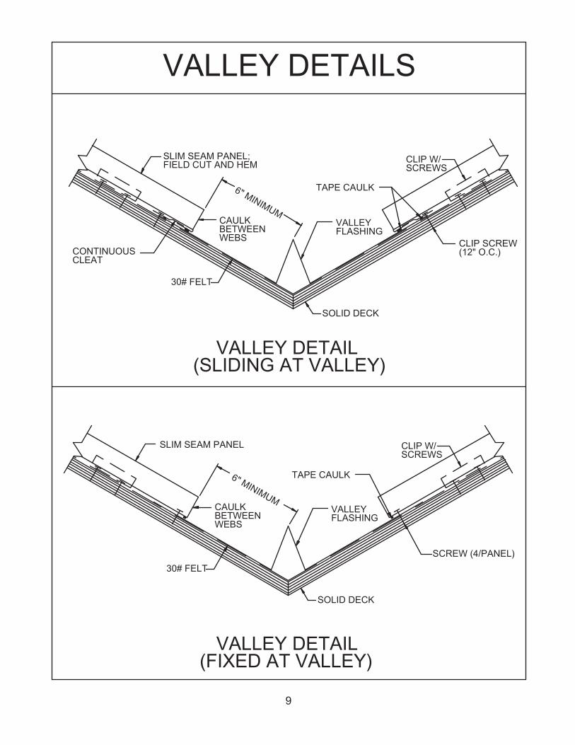
VALLEY DETAILS
CLIP W/SCREWS
SOLID DECK
(SLIDING AT VALLEY)VALLEY DETAIL
CONTINUOUS
SLIM SEAM PANEL;
BETWEENWEBS
30# FELT
CAULK
FIELD CUT AND HEM
6" MINIMUM
FLASHINGVALLEY
TAPE CAULK
CLIP SCREW(12" O.C.)
CLEAT
SCREW (4/PANEL)
SOLID DECK
(FIXED AT VALLEY)VALLEY DETAIL
SLIM SEAM PANEL
30# FELT
CLIP W/
VALLEYFLASHING
WEBS
6" MINIMUM
BETWEENCAULK
TAPE CAULK
SCREWS
9

DETAILS
#43 POP RIVET
DRIP TRIM
2' O.C.WALL TRIMPOSI-LOCK
SOFFIT PANEL
#43 POP RIVET TO FASTEN;CAULK AS REQUIRED
BEND AS REQUIRED; USEPRENOTCHED SEAM COVER;
FIELD CUT VERTICALLEG OF PANEL AND BENDAS REQUIRED.
SOLID DECK
30# FELT
CLIP W/SCREWS
ROOF/FASCIA TRANSITION (FIXED AT TRANSITION; REQUIRES SLIDING
RIDGE AND SLIDING END)
CONT. SEALANT
CONT. HEM
TYPICAL REGLET
SIDEWALL DETAIL
FIELD CUT AND BENDSLIM SEAM PANEL
30# FELTSOLID DECK
CONT. CLEAT
GABLE DETAIL
(12" O.C.)
SOLID DECK30# FELT
FASCIA BOARD
(12" O.C.)SCREW
SEALANT TAPEGABLE TRIM
SCREW
SLIM SEAM PANEL
WGF-1WGC
10
3449 Hempland Road, Lancaster, PA 17601
Route 24 West, Gridley, IL 71744 308 Alabama Blvd., Jackson, GA 30233
Route 3, Box 632, Idabel, OK 74745 2402 Industry Way, Cedar City, UT 84720
658 Boekel Road, Rathdrum, ID 83858 1820 East 26th St., Marshfield, WI 54449
Highway 41 South & 55 Lamb Loop Road, Tifton, GA 31793
World Wide Web address: www.fabral.com e-mail address: [email protected]
A-300 98-32-623
© FABRAL 2002 02/02 2.5K APC