Sliding mechanics
94
Sliding mechanics By Neethu Philip
Transcript of Sliding mechanics
Sliding mechanicsBy Neethu Philip

INTRODUCTION
Orthodontic tooth movement during space closure is
achieved through 2 types of mechanics
The first type, segmental or sectional mechanics,
involving closing loops fabricated either in a full or sectional
arch wire.
The second type, sliding mechanics involves either
moving the bracket along an arch wire or sliding the
archwire though brackets and tubes.
The main differentiating factor between 2 types of
mechanics pertains to FRICTION. Since sectional
mechanics do not involve friction it is called friction
free or friction less technique.
On the other hand, friction plays a significant role in
sliding space closure; therefore it is called friction
mechanics.
INTRODUCTION
FRICTION
Friction is the resistance to motion that exists when a solid
moves tangentially with the respect to the surface of another
solid.
FRICTIONAL FORCE FFR : Is parallel but opposite to the
direction of force (F) causing motion.
The frictional force produced is proportional to the force with
which the contacting surfaces are pressed together and is
affected by the nature of the surface at the interface.
FRICTION
Friction is independent of the apparent area of contact.
There are two components of friction – static and
kinetic.
STATIC FRICTIONAL FORCE:
Tangential force that does not cause any motion of the
contacting parts. It reflects the force necessary to initiate
movement.

FRICTION
KINETIC FRICITIONAL FORCE: Is the tangential
force which acts between the sliding surface moving
at a constant speed and it reflects the force necessary
to perpetuate this motion.
Kinetic co-efficient of friction is smaller than static
co-efficient of friction.

STICK-SLIP PHENOMENON
When a tangential force is applied to cause one material to slide past the other, the junctions begin to shear.
At low sliding speeds, a “stick slip” phenomenon may occur as enough force builds up to shear the junctions and a jump occurs, then the surfaces stick again until enough force again builds to break them.

A single stick-slip cycle involves a stick state associated with elastic loading of the system, followed by a sudden slip corresponding to stress relaxation
STICK-SLIP PHENOMENON

MECHANISM OF ACTION OF FRICTION MECHANICS :
To move a tooth bodily, the force applied has
to pass through the center of resistance of the tooth.
However as the force is applied at the bracket level
of the crown, the concerned tooth experiences both
force and moment.

MECHANISM OF ACTION OF FRICTION MECHANICS :
Moment of force is created in 2 planes of space. One
moment tends to rotate the canine mesial out as the force
application is buccal to the center of resistance and the
other tends to cause distal tipping of the tooth as the point
of force application is occlusal to the center of resistance.
MECHANISM OF ACTION OF FRICTION MECHANICS :
The wire bracket interaction tends to counteract this
moment by applying an opposite moment. When
distal tipping of the crown takes place the M/F ratio
will be around 7:1, the tooth slides along the
archwire till binding occurs between the archwire and
the bracket. This produces a COUPLE at the bracket.
MECHANISM OF ACTION OF FRICTION MECHANICS :
Now the M/F ratio increases to 12:1, which results
in distal root movement and uprighting of the
tooth.As the tooth uprights, the moment decreases
until the wire no longer bends. The process is
repeated until the tooth is retracted and force is
depleted

ROLE OF FRICTION IN ELICITING
BIOLOGICAL RESPONSE-(AJO 1980 DEC - FRANK &
NIKOLAI)
When sliding mechanics are used, friction
occurs at the bracket wire interface. Some of the
applied force is dissipated as friction and the
remainder is transferred to the supporting structures
of tooth to mediate tooth movement.
ROLE OF FRICTION IN ELICITING BIOLOGICAL RESPONSE-(AJO 1980 DEC - FRANK & NIKOLAI)
Upon activation, only when the delivered force is
sufficient to overcome the static frictional force,
teeth are displaced. Movement continues until the
resistance of deformed pdl builds to a value, which
when added to kinetic frictional force offsets the
delivered force and tooth movement temporarily
ceases.

ROLE OF FRICTION IN ELICITING BIOLOGICAL
RESPONSE-(AJO 1980 DEC - FRANK & NIKOLAI
As time proceeds, periodontal remodeling affects the
resistance potential and other factors like wire
resiliency and masticatory action alter the mean
resultant normal force between the bracket and the
wire, so that friction lock is broken & tooth
movement resets again.
FORCE DELIVERY SYSTEMS IN SLIDING MECHANICS
1. Elastic module with ligature
2. E - chains
3. closed coil springs
4. J - hook head gear
5. Mulligan’s V - bend sliding mechanics (JCO 1980
July 1994 Sep)
6. Employing Tip-edge Bracket on canines

METHODS OF CANINE RETRACTION IN SLIDING MECHANICS
There are two ways in which anterior teeth are
retracted.
1. By retracting the canine first followed by retraction of
other four anteriors enmasse.
2. Enmasse retraction of six anterior teeth.
Among the above mentioned force delivery system,
commonly used are the elastomeric materials and the
closed coil spring.

They are either attached directly to attachments on the teeth
(canine hooks) or more usually to hooks on the archwire
Methods of applying traction to the archwire include
Fabricated tie back loops (in shape of boot or inverted boot)
Soldered brass hooks (0.7mm)
Stainless steel hooks (0.6mm)
Crimpable hooks
Kobayashi hooks
Preposted archwires are also available

Tie back loops are difficult to bend in preformed
archwires and negate many of their advantages
Soldering requires chair side or laboratory
equipment and is time consuming. It may lead to
annealing of the archwire.
Preposted archwires with soldered brass or SS hooks
allow large inventory of stock and has cost
implications.

PREPOSTED ARCHWIRES
They are available in 3 sizes
The average distance between the
hooks are 38mm in the upper arch
and 26 mm in lower arch (this suits
more than half of the patients).
Additional sizes 41 mm (U) & 35
mm (L)
28 mm (U) &
24mm (L)
CRIMPABLE ARCH WIRE HOOKS
Crimpable arch wire hooks allow quick and simple
placement of hooks in the desired position on the arch
wire in (or) out of the mouth.
Cost saving both in time and materials.
It is associated with minimum discomfort.
Excessive force during crimping caused GABLING of
the wire and introduction of unwanted force into the
wire.

GRIFFIN & FERRACANE (1998) examined the effect of
addition of sandblasting and dental adhesive on the stability
of the crimpable hooks. The combination increased the force
required to dislodge the hook by a factor of 10. The typical
crimping force was found to be 18 kg.
CRIMPABLE ARCH WIRE HOOKS

KOBAYASHI HOOKS
Employed during canine retraction and in the
settling phase. Prefabricated ones are also available.
It can be custom made from 0.09” or 0.010” ligature
wire.
FORCE DELIVERY SYSTEM :
ELASTOMERICS:
Composition and structure
Elastomeric modules and E-chains are polyurethanes,
which are thermosetting polymers. The polymers
posses rubber like elasticity and have long chain
which are lightly cross-linked. The cross-links
between chains must be relatively few to facilitate
large extension with no rupture of primary bonds.

1. ELASTIC MODULES WITH LIGATURE : ( Active
tiebacks)- This method was popularized by BENETT &
MCLAUGHLIN (controlled space closure with
preadjusted appliance system) JCO 1990 April. They
recommend placing 0.019” x 0.025” SS in a 0.022 slot for
atleast one month with passive tie backs before attempting
space closure.
Hooks of 0.024” SS or .028” brass are soldered to upper
and lower archwires.
FORCE DELIVERY SYSTEM :

Active tie backs
An elastic module is stretched by 2-3mm(ie) twice its normal
length and it usually delivers 0.5 - 1.5mm of space closure per
month. Tie backs are replaced every 4-6 weeks. Modules
generate 50-100 gm of force if module was pre stretched before
use. If used directly from manufacture without pre-stretching
force delivered is greater. There are 3 methods of placing active
tie backs with elastic modules .

Type 1: active tiebacks
Type 1: active tiebacks. This is the most frequently used method.
The .019x .025 rectangular steel archwire is placed, with modules
or wire ligatures on all brackets. The elastomeric module is
attached to the first or second molar hook. A .010 ligature is used,
with one arm beneath the archwire. This makes the active tieback
more stable, and helps to keep the ligature wire away from the
gingival tissues. An elastomeric module is stretched to twice its
size.

Type 2 active tieback
This follows the same principle as type 1, but the elastomeric module is attached to the soldered brass hook on the archwire. The.019x.25 rectangular steel archwire is placed with elastomeric modules or wire ligatures on all brackets, except the premolar brackets. A.010 wire ligature is attached to the first or second molar hook, with several twists in the wire, and then attached to an elastomeric module on the archwire hook. Finally, a normal module is placed on the premolar brackets to cover the tieback wire and the archwire.

Type 3 active tieback This is a recent innovation introduced by Dr. Trevisi, which he
is currently evaluating. It is modification of the type 2 active tieback. It may have the advantage of being cleaner, with less friction. The 0.19x.025 rectangular steel archwire is placed with elastomeric modules on all brackets, except the premolar brackets. A. 010 wire ligature is attached to the first or second molar hook, with several twists in the wire. The 0.10 wire ligature is also used to loosely ligate the premolar bracket, and is then attached to an elastomeric module on the archwire hook.

TRAMPOLINE EFFECT It has been shown that space closure can continue for
several months in a patient who has failed to present for normal adjustments even when the elastomeric module is in poor condition and delivering very little force. This might be due to a trampoline effect which occurs during mastication and which can result in an intermittent pumping activation.
This jiggling motion is greater in the lower arch and in low – angle cases with heavier masticatory forces. These presumed differences would conveniently meet clinical requirements as normally more forces are required for lower space closure and in low angle cases.
2. E – CHAIN (ELASTOMERIC CHAINS)
It was introduced in 1960 and used in orthodontics
for canine retraction, diastema closure, rotation
correction and arch constriction.
Most of the elastomeric chains generally lose 50% -
70% of their initial force during the 1st day of load
application and at 3 weeks retain only 30 – 40% of
their original force.

In view of the wide variation of initial force levels of
different types of power chains, a force gauge should
be used to determine the desired initial force.
To overcome the problem of rapid force decay
rate and provide for a more constant and consistent
force delivery, prestreching of elastomeric chains has
been suggested.
2. E – CHAIN (ELASTOMERIC CHAINS)

CONFIGURATIONS
Elastomeric chains are available in 3
configurations
Closed loop chain
Short filament chain
Long filament chain :
- generally deliver a lower initial force
and exhibit a greater rate of force
decay at the same extension.

CLINICAL CONSIDERATIONS WHEN USING ELASTICS FOR RETRACTION OF CANINES
A common mistake is to change the elastic chain or
module too often, thus maintaining high force levels and
a moment to force ratio that produces distal crown
tipping only. This also causes excessive mesial out
rotation of the canines. Constantly high force levels can
cause excessive hyalinization of the periodontal
ligaments and inhibit direct resorption around the canine.
If the posterior segment undergoes direct bone
resorption at the same time, loss of anchorage may
result. It is therefore recommended that elastic
modules or chain should be changed at an intervals
of 4-6 weeks to optimize sliding retraction of the
canine.
CLINICAL CONSIDERATIONS WHEN USING ELASTICS FOR RETRACTION OF CANINES
Advantages
absorb water and saliva and
permanent staining takes place.
Stretching causes permanent
deformation.
The loss of force (FORCE
DECAY) with time leads to
variable forces levels during the
treatment, this results in
decreased effectiveness.
Disadvantages
Inexpensive,
Relatively hygienic,
Can be easily applied
without arch wire
removal
No patient co-operation
required.

3. CLOSED COIL SPRINGS
Coil springs were introduced to the orthodontic world as early
as 1931. During the manufacturing process, the material is
subjected to winding that includes tensional and torsional
components and hence spring properties may be slightly
different from the wires made from the same material. The
various materials that have been used for making springs are
Stainless steel
NiTi
Co-Cr Ni alloy
a. Stainless Steel coil spring
Stainless steel coil springs are efficient methods of retraction. They apply more predictable levels of forces compared to elastic based systems described before. They are easy to apply
However, stainless steel springs have a relatively higher load deflection rate compared to some other material springs like NiTi springs. So, as the space starts to close, there is some force degradation due to lessening activation.
Moreover, the force applied depends to some extent on the level of activation. Hence there may be a tendency to apply excessive force initially by over activation. Thus, the amount of activation has to be monitored to maintain ideal force levels.
a. Stainless Steel coil spring

b. NiTi closed coil springs
Nickel titanium alloys were introduced to the
dental profession by William. P. Bleur in the
1960's. He demonstrated the unique combination
of properties of shape memory and super
elasticity in addition to low modulus of
elasticity, moderately high strength, high
resilience and less corrosion.

The force degradation is very less due to the low load deflection rate. They deliver constant amount of force till they reach the terminal end of deactivation stage and generally close space with single activation. They are available in lengths of 9 mm and 11 mm.
b. NiTi closed coil springs
ADVANTAGES OF NITI COIL SPRINGS
Can be easily placed and removed without archwire removal
Do not need to be reactivated at each appointment Patient co-operation not required.
DISADVANTAGES Relatively unhygienic compared to elastic force
systems.

In 1992 Angolkar et al examined the force
degradation of SS, COCR and NiTi coil springs and
found major force loss to occur after 24 hours. 17%
for SS, 10% for cobalt chromium, 3% NiTi spring.
Thus the clinician should consider a force decay of
8% to 20% when retracting with coil springs against
the force decay of 70% with modules and 42% with
latex elastic.

FORCE CHARACTERISTICS OF NITI COIL SPRING (Heinz Tripolt, Chasrles Burstone (Ajo 1999, 15 : 498 – 507)
A standardised NiTi closed coil springs can produce a relatively constant force during deactivation.
Super elastic (SE) NiTi coil spring are extremely temperature sensitive and thus produce a large force variation at different mouth temperatures. However in a narrow temp range, this variation is small.
NiTi springs with clinically targeted values of 100gm, 150gm and 200gm ever found to have little difference.
The force magnitude varied depending on mouth temperature.
COMPARISON OF RATE OF SPACE CLOSURE USING NITI SPRING AND AN ELASTIC MODULE. (Samuels, Rudem and Mair AJO 1998 – 1993)
The use of SE Niti coil springs resulted in significant greater and more consistent rate of space closure than elastic module.
Optimal force for space closure is 150gm when using NiTi coil spring and found to be more effective than 100gm springs.
When examined clinically there was no difference in tooth position produced by 2 system after space closure.
No evidence of greater patient discomfort with the spring.

EFFECT OF ENVIRONMENTAL FACTORS ON E- CHAIN & NITI-COIL SPRINGS. Claire Nattrass (EJO-1998-vol20/169-176)
Temp variations affected both E-chain and NITI coil springs
E-chains – Effect of temp was more profound. Force loss
greater at higher temp.
NITI springs- overall effect of temp was smaller. Force loss
greater at lower temp.
This is due to modifications in the crystal structure of the
alloy

E-Chains are also affected by other environmental factors
such as food. The gross colour change is a common clinical
finding in patients who consume spicy foods.
Force decay of E-chain was more in carbonated drinks than in
water which may be due to low PH.
But Ferriter in 1990 found that acidic fluoride environment
reduced the level of force decay exhibited by elastomers.
EFFECT OF ENVIRONMENTAL FACTORS ON E- CHAIN & NITI-CORT SPRINGS. Claire Nattrass (EJO-1998-vol20/169-176)

4. DIRECT HEADGEAR RETRACTION
J hook headgear, either of the straight pull or high pull type
is clipped on the archwire mesial to the canines to slide them
distally.
Straight pull headgear allows swifter canine retraction than
the high pull type. However, this may cause anterior
extrusion (Perej et al 1980; Hickham 1974) and
unfavourable occlusal plane rotations (Bowden 1978). This
might specially be a problem in high maxillomandibular
angle cases.
4. DIRECT HEADGEAR RETRACTION
High pull headgear may cause more bodily
retraction. However, it is not as efficient for distal
movement, needing prolonged periods or wear for
modest results.
During the retraction, direction of force may be
varied between straight pull and high according to
the individual requirements of the case.
4. DIRECT HEADGEAR RETRACTION
Advantages Anchorage conservation is
good. Additional molar support by head gear may be done.
Overjet reduction might occur during canine retraction due to the distal force and binding of the archwire.
Can be applied to both upper and lower arches simultaneously
Disadvantages As force application is
intermittent this is slower than other methods of canine retraction.
Highly dependent on patient co-operation.
The molar and buccal segment correction is usually a later event in treatment compared to other systems.
Canine tipping and anterior extrusion can occur with the straight pull headgear.

5. MULLIGAN'S V BEND SLIDING MECHANICS
introduced by Mulligan in the 1970's.
The basic principle was to apply different moments to the teeth
via bends in the continuous archwire while force for retraction
was applied by auxiliaties like elastic chain, coil spring etc.
In the 0.018 slot, 0.016 SS wire is used for retraction
while in the 0.022 slot, 0.016, 0.018 or 0.020 wires may be
used.
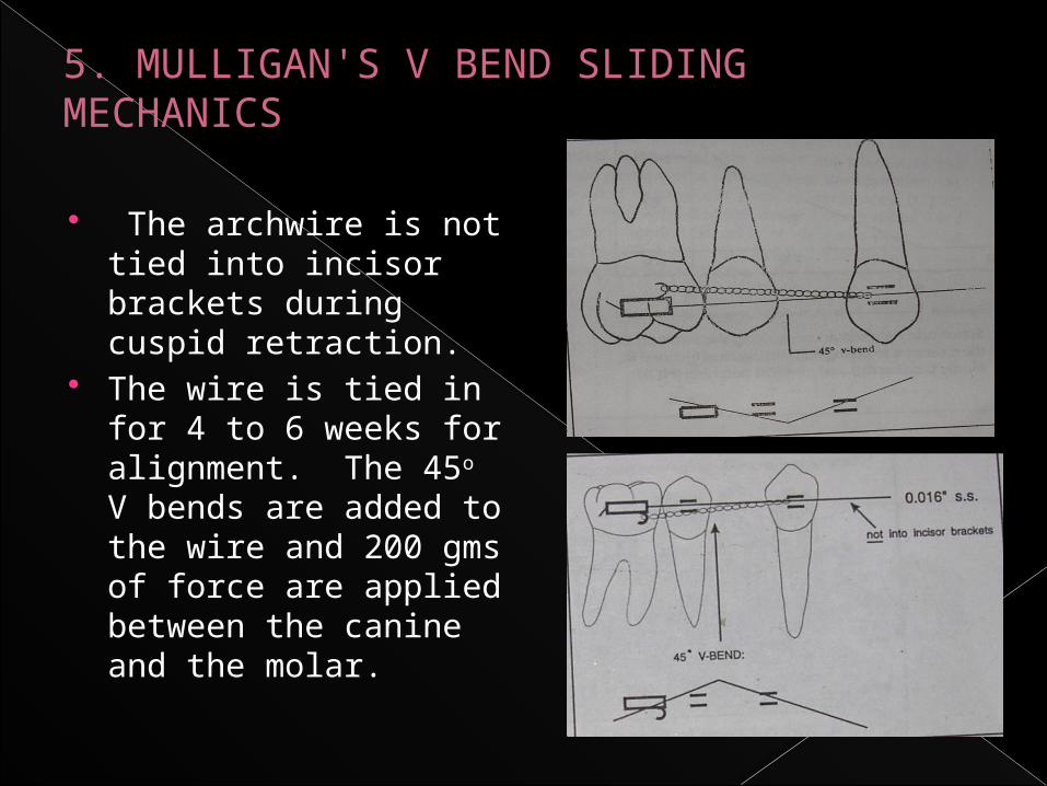
The archwire is not tied into incisor brackets during cuspid retraction.
The wire is tied in for 4 to 6 weeks for alignment. The 45o V bends are added to the wire and 200 gms of force are applied between the canine and the molar.
5. MULLIGAN'S V BEND SLIDING MECHANICS
If the bend is placed offcenter it creates a short and a long
segment. The shorter segment is more rigid and hence applies
greater moments. So, if maximal canine retraction is required
the bend is placed very close to molar . The longer span of
wire towards the canine allows some tipping to occur as the
moment is less. Thus the canine gets retraced by tipping and
uprighting. As the canine retracts, the bend goes on becoming
less offcentered and mesial crown uprighting moments on the
canine increase.
5. MULLIGAN'S V BEND SLIDING MECHANICS

EFFECTS OF OVERLY SPACE CLOSURE:
Space closure typically occurs more easily in high angle patterns with weak musculature. The rate of closure can be increased either by increasing the force or using thinner arch wire. However more rapid space closure leads to
loss of control of torque, rotation or tip

Loss of control of torque
results in upper incisors being too upright at the end of
space closure with the spaces distal to the canines and
a consequent unesthetic appearance. The lost torque is
difficult to regain. Also, rapid mesial movement of the
upper molars can allow the palatal cusps to hang down,
resulting in functional interferences, and rapid
movement of the lower molars causes “rolling in “.

Loss of control of torque
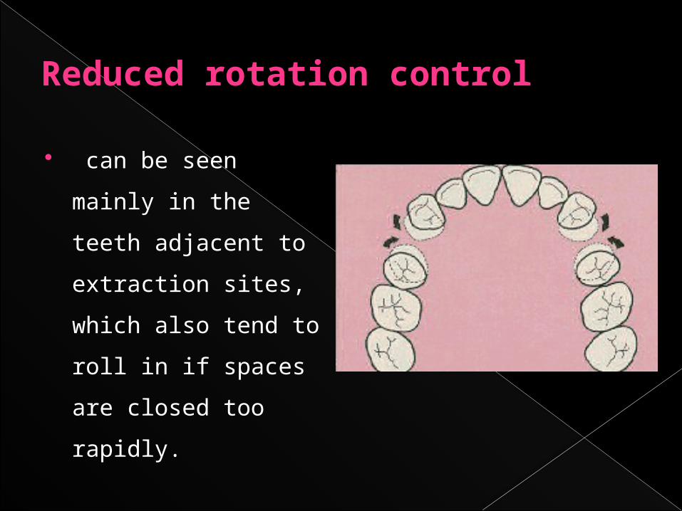
Reduced rotation control
can be seen mainly in
the teeth adjacent to
extraction sites, which
also tend to roll in if
spaces are closed too
rapidly.
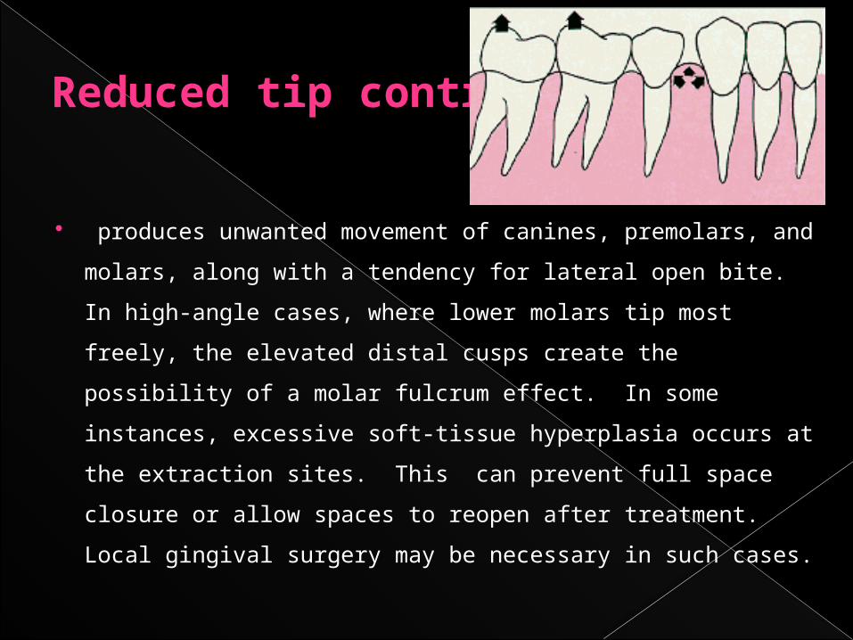
Reduced tip control
produces unwanted movement of canines, premolars, and
molars, along with a tendency for lateral open bite. In high-
angle cases, where lower molars tip most freely, the elevated
distal cusps create the possibility of a molar fulcrum effect. In
some instances, excessive soft-tissue hyperplasia occurs at the
extraction sites. This can prevent full space closure or allow
spaces to reopen after treatment. Local gingival surgery may be
necessary in such cases.

INHIBITORS TO SLIDING MECHANICS
1. Occlusal interference - To prevent this proper aligning
and leveling of the arches is required.
2. Friction and binding between bracket and archwire
may place heavy demand on anchorage.
3. Poor canine control can be a problem : Doing canine
retraction on heavier arch wire reduces the problem.

4. Cortical plate resistance (Narrowing of alveolar bone in extraction
sites)
5. Excessive forces causes lower molar tipping and extrusion of
distal cusps
6. Soft tissue build up in the extraction site can prevent space closure
(or) reopen spaces after treatment.
7. Rotation of canines mesio-bucally and molar mesiopalatally.This
occurs due to the use buccal traction. It can be prevented
simultaneous palatal traction using lingual cleats or buttons.
INHIBITORS TO SLIDING MECHANICS

VARIABLES AFFECTING FRICTIONAL RESISTANCE DURING TOOTH MOVEMENT
PHYSICAL VARIABLES:1. Archwire: Material Cross sectional shape/ size. Surface texture. Stiffness. 2. Ligation of archwire to bracket: Ligature wires. Elastomerics. Method of ligation / Self ligating brackets

3. Bracket properties: Material Manufacturing process. Slot width and depth. Design of bracket: single/twin. First order bend (in-out) Second order bend (angulation). Third order bend (torque).4. Orthodontic appliance: Inter bracket distance. Level of bracket slots between adjacent teeth. Forces applied for retraction.
VARIABLES AFFECTING FRICTIONAL RESISTANCE DURING TOOTH MOVEMENT

BIOLOGICAL VARIABLES:
Saliva
Plaque
Acquired pellicle.
Corrosion.
Food particles.
VARIABLES AFFECTING FRICTIONAL RESISTANCE DURING TOOTH MOVEMENT

EFFECT OF BRACKET MATERIAL, DESIGN AND MANUFACTURING PROCESS ON FRICTION :-
Various Bracket materials today available are :-1. Stainless steel Cast
Sintered 2. Ceramic brackets Polycrystalline aluminaSingle Crystalalumina (SCA) (i.e Sapphirc)3. Zircoma brackets4. Plastic brackets

1. Stainless Steel Brackets :- Most popular bracket material
Stainless steel brackets are associated with lowest frictional force values amongst the available bracket materials
Kapila et al (1990) Evaluated friction b/n Edgewise SS
brackets and orthodontic wires of 4 alloys (SS, Co- Cr, NiTi and B-Ti)
Mean frictional forces with conventional cast stainless steel brackets ranges between 40-336 g.
Level of frictional forces observed in :- 0.018inch SS brackets – Ranged from 49g with 0.016
inch SS wires in narrow single brackets to 336g with 0.017 x 0.025 inch B-Ti wires wide twin brackets.
0.22 inch SS brackets – Friction ranged from 40g 0.018 inch SS wires in narrow brackets to 222g with 0.019 x 0.025 inch NiTi wires in wide brackets.
Several SS bracket wire combinations generated low levels of frictional forces less than 100g.
SINTERED STAINLESS STEEL BRACKETS Sintering : Process of fusing individual particles together after compacting them under heat and pressure.
Sintering allows individual bracket to be premolded in a smooth stream lined manner. The SS particles are compressed in a contoured smooth rounded shape as apposed to older casting procedure in which milling or cutting pro cess left sharp angular brackets that were bulky and rough.

Sintered edgewise brackets RMO Mini Taurus.
RMO Mini Taurus SynergyUnitek Mini Twin.
Sintered SS brackets produce significantly lower friction than cast stainless steel brackets overall friction of sintered SS brackets is approx 40% - 45% less than friction of conventional cast stainless steel brackets
2) CERAMIC BRACKETS : With ceramic brackets, most of wire size
and alloy combinations with both 0.018 and 0.022 inch slot sizes demonstrate significantly higher fric tional forces than with SS brackets.

Characteristics of Ceramic Bracket Material or Slot Surface Texture:
Highly magnified views have revealed numerous generalized small indentations in the ceramic bracket slot while the SS bracket appeared relatively smooth.
Hardness of the materialAll currently available ceramic brackets are composed of Aluminium oxide.Aluminium oxide is extremely hard.
The rough but hard ceramic material is likely to penetrate the surface of even a steel wire during sliding, creating a considerable resistance and this is worse with titanium wires
The interaction of metal wire - ceramic slot interface leads to leveling of ceramic slot. This results in drop in friction as ceramic peaks are removed and valleys become clogged with metal
Types of Ceramic brackets : - Single Crystal alumina (SCA) - Polycrystalline alumina (PCA)
monocrystalline alumina :- Single crystal ceramic brackets are derived from large single crystals of Alumina which are milled into desired shape and dimensions by ultrasonic cutting, diamond cutting or combination of two techniques. Because Alumina is third hardest known material, this procedure is difficult and may explain granular and putted surface of ceramic brackets seen in SEM

Polycrystalline brackets - have also been observed under SEM to possess very rough surfaces which actually scribed grooves into the archwire
Monocrystalline brackets were observed to be smoother than PCA brackets but their frictional properties were comparable.
The most apparent difference b/n polycrystalline and single. crystal brackets is their optical clarity. Single crystal brackets are noticeably clearer than PCA brackets which tend to be translucent
Clinical significance :- Combination of metal archwires and
Ceramic brackets produce high magnitudes of frictional force; therefore greater force is needed to move teeth with ceramic brackets compared to SS brackets in sliding mechanics.

Since ceramic brackets on anterior teeth are often used in combination with SS brackets and tubes on premolar and molar teeth, retracting canines along archwire may result in greater loss of anchorage because of higher frictional force associated with Ceramic than SS brackets.
To reduce frictional resistance Ceramic brackets with smoother slot surfaces and consisting of metallic slot surface are avaliable

) ZIRCONIA BRACKETS : Besides high friction, Ceramic brackets
have very low fracture resistance Due to their brittle nature even smallest crack or flaw can propagate rapidly through the material.
Zirconia brackets have been offered as an alternative to ceramic brackets since surface hardening treatments to increase fracture toughness are available for Zirconium oxide.

Frictional coefficients of Ziconia brackets were found to be greater than or equal to those of poly crystalline alumina brackets in both dry and wet states (Keith et al , 1994). Surface changes consisting of wire debris and surface damage in Zirconia brackets after sliding of archwires were also observed.

) PLASTIC BRACKETS : In an attempt to create an esthetic bracket
with lower frictional resistance and easier debonding features than ceramics a varity of new, ceramic reinforced plastic brackets with or without metal slot inserts have been introduced.

Trade Name Company Type
E.g: Silkon American Orthodontics Plastic reinforced with ceramic
Spirit Ormco Plastic with metal insert
Image GAC Plastic reinforced with glass
Clarity Unitek Ceramic with metal insert
Cermaflex TP Metal with plastic base

Plastic brackets can deform because of compression from ligation and thus binding of the wire, and higher frictional resistances were recorded than stainless steel brackets. Recently introduced composite brackets with and without metal slots faired better in friction studies showing lower frictional resistance than both ceramic and stainless steel brackets in one of the studies.

EFFECT OF BRACKET WIDTH ON FRICTION Effect of bracket width on friction has been controversial - Some studies have found that altering bracket width
made no difference in friction (Peterson et al 1982, Andereasen et al, 1970).
- Frictional resistance has been reported to increase with increase in bracket width (Tidy 1989, Drescher et al, 1989).
- Whereas others found that frictional resistance decrease as bracket width increased.
· Franks and Nikolai (1980) :- Related greater friction with wider brackets to the fact that binding occurs frequently with wider brackets.
Omana et al suggested that with a narrow bracket the tooth could tip considerably before binding could occour,and once binding occurs it was of severe nature
Kapila et al (1990 and Ogata et al (1996) : Suggested that with a wider bracket the
elastomeric ligature used was stretched more than with a narrower bracket which exerted a greater normal force on the wire

Bracket Width and Interbracket Distance (IBD) Bracket width is closely related to IBD
Narrower the bracket
Greater the length of interbracket wire
Greater the flexibility of wire
Decrease in stiffness of wire
Greater chance of binding with more flexible wire.
Bracket slot size may not influence the frictional resistance,
some studies suggested that frictional resistance decreased as slot size increased from 0.018 inch to 0.022 inch because of reduced binding probably from increased wire stiffness. And also because of the increased play in the slot with final archwire

ADDITIONAL DESIGN FEATURES IN
BRACKETS TO REDUCE FRICTION
Bumps on the bracket slot walls and floor which decreased surface contact with the wires, help decreased friction in bracket wire interface. (Ogata etal)
Begg brackets—have achieved low friction by virtue of an extremely loose fit between a round archwire and a very narrow bracket, but this is at the cost of making full control of tooth position correspondingly more difficult. Some brackets with an edgewise slot have incorporated
shoulders to distance the elastomeric from the archwire and, thus, reduce friction, but this type of design also produces reduced friction at the expense of reduced control.

EFFECT OF SECOND ORDER DEFLECTION OF
FRICTION
Second order defection of wire b/n brackets held in series can have significant effects on brackets wire friction.
- Several studies have found that increasing the angulation between bracket and wire produced greater friction.

Frank and Nikolai (1980) :- Found that frictional resistance increased in a nonlinear manner with bracket angulation.
With brackets out of alignment archwire stiffness, strongly influences forces normal to the points of contact and hence friction.
In a well aligned arch forces that result from archwire deflection are not important and friction is largely independent of archwire stiffness

Ogata et al (1986) Evaluated the effects of different bracket wire combinations and 2nd order deflections on kinetic friction. The brackets were offset deflecting wire in increments of 0.25 mm
As 2nd order deflection increased frictional resistance increased for every bracket wire combination - With lower deflections a smooth sliding phase appeared in which friction increased in approximate a linear manner.

As deflection increased further a binding phase occured in which friction increased at a much greater rate and was not necessarily linear.
Binding generally occured between 0.75 and 1.00 mm of 2nd order deflection.
The relationship between frictional resistance and second order angulation may not be linear and may become more important as the angulation increases. The active configuration for binding occurred between 3 to 7°.

When tipping occurs the frictional resistance of nickel-titanium has been reported to be less than stainless steel,
Because of the lower modulus of elasticity of nickel-titanium compared with stainless steel, lower normal force that was induced by binding occurred resulting in less resistance to sliding.

CONCLUSION: The potential risks of friction and binding are
now reduced but not totally eliminated from sliding mechanics. However it remains the most widely used method of canine retraction in clinical practice. So the orthodontist must be aware that even with best archwire / bracket combination (SS / SS), atleast 40 gms of friction must be included in the force applied to the tooth to initiate movement during sliding mechanics.