
Slidematic Facebow Slidematic Gesichtsbogen Le...
44
Slidematic Facebow Instruction Manual Slidematic Gesichtsbogen Gebrauchsanleitung Le mesureur facial Slidematic Manuel d’utilisation Arco Facciale Slidematic Manuale D’Istruzione Arco Facial Slidematic Manual de Instrucciones
Transcript of Slidematic Facebow Slidematic Gesichtsbogen Le...

Slidematic FacebowInstruction Manual
Slidematic GesichtsbogenGebrauchsanleitung
Le mesureur facial SlidematicManuel d’utilisation
Arco Facciale SlidematicManuale D’Istruzione
Arco Facial SlidematicManual de Instrucciones


I. Rationale for Development ............................................... 2II. Benefits and Features ........................................................ 2III. Slidematic Facebow Procedure ........................................ 4IV. Mounting Procedure ......................................................... 6V. Slidematic Accessories ..................................................... 8VI. Reordering ......................................................................... 8VII. Warranty ............................................................................ 8
1
Table of Contents
Please check online at www.whipmix.com for the most current
instructions and parts list.
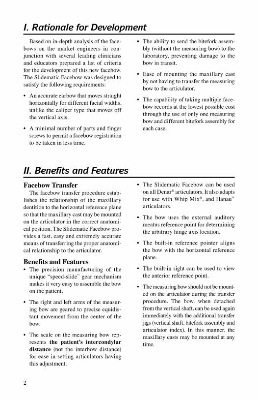
I. Rationale for DevelopmentBased on in-depth analysis of the face-
bows on the market engineers in con-junction with several leading clinicians and educators prepared a list of criteria for the development of this new facebow. The Slidematic Facebow was designed to satisfy the following requirements:
• Anaccurateearbowthatmovesstraighthorizontally for different facial widths, unlike the caliper type that moves off the vertical axis.
• Aminimalnumberofpartsandfingerscrews to permit a facebow registration to be taken in less time.
• Theabilitytosendthebiteforkassem-bly (without the measuring bow) to the laboratory, preventing damage to the bow in transit.
• Ease ofmounting themaxillary castby not having to transfer the measuring bow to the articulator.
• Thecapabilityoftakingmultipleface-bow records at the lowest possible cost through the use of only one measuring bow and different bitefork assembly for each case.
II. Benefits and FeaturesFacebow Transfer
The facebow transfer procedure estab-lishes the relationship of the maxillary dentition to the horizontal reference plane so that the maxillary cast may be mounted on the articulator in the correct anatomi-cal position. The Slidematic Facebow pro-vides a fast, easy and extremely accurate means of transferring the proper anatomi-cal relationship to the articulator.
Benefits and Features• The precision manufacturing of the
unique “speed-slide” gear mechanism makes it very easy to assemble the bow on the patient.
• Therightandleftarmsofthemeasur-ing bow are geared to precise equidis-tant movement from the center of the bow.
• Thescaleon themeasuringbowrep-resents the patient’s intercondylar distance (not the interbow distance) for ease in setting articulators having this adjustment.
• TheSlidematicFacebowcanbeusedon all Denar® articulators. It also adapts for use with Whip Mix®, and Hanau™ articulators.
• The bow uses the external auditorymeatus reference point for determining the arbitrary hinge axis location.
• The built-in reference pointer alignsthe bow with the horizontal reference plane.
• Thebuilt-insightcanbeusedtoviewthe anterior reference point.
• Themeasuringbowshouldnotbemount-ed on the articulator during the transfer procedure. The bow, when detached from the vertical shaft, can be used again immediately with the additional transfer jigs (vertical shaft, bitefork assembly and articulator index). In this manner, the maxillary casts may be mounted at any time.
2

3
• In one step the bitefork assembly is
secured to the articulator index and maxillary cast can be mounted to the articulator.
• Allfingerscrewsareeasilyaccessiblefrom the front.
• Theprocedurescanbereadilydelegat-ed to auxiliary personnel.
For a further breakdown, refer to Denar® Slidematic Facebow Parts List #8815-1.
Sterilize bitefork before each use.
Measuring Bow1. earplug2. anterior reference pointer3. intercondylar distance
scale4. “finger” lockscrew5. Center “lock” wheel6. Sight
Transfer Jig Assembly1. dentulous bitefork2. bitefork index notch3. vertical shaft4. articulator index
reference plane locator reference plane marker
1
2
3
4
1
2
3
45
6
Measuring Bow1. earplug2. anterior reference pointer3. intercondylar distance
scale4. "finger" lockscrew5. center "lock" wheel6. sight
Transfer Jig Assembly1. dentulous bitefork2 bitefork index notch3 vertical shaft4 articulator index
reference plane locator reference plane marker
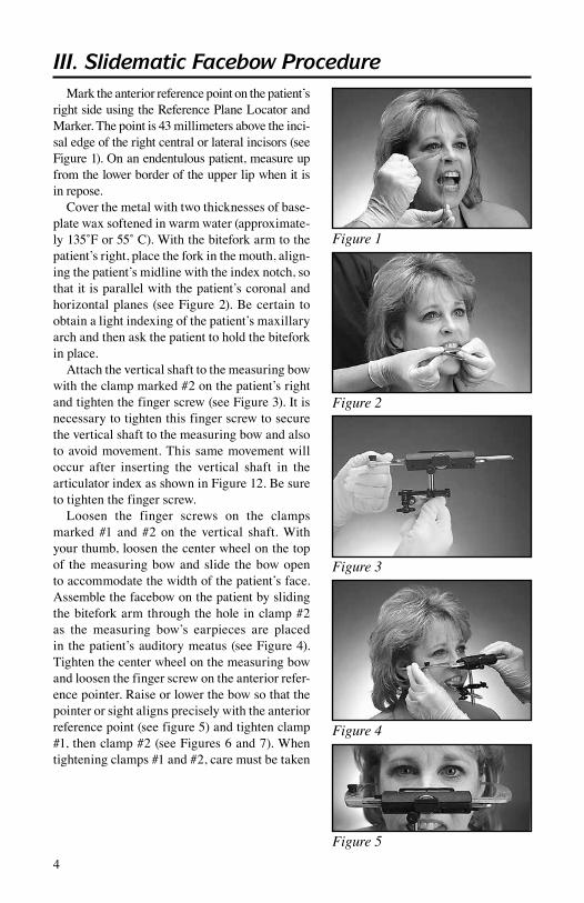
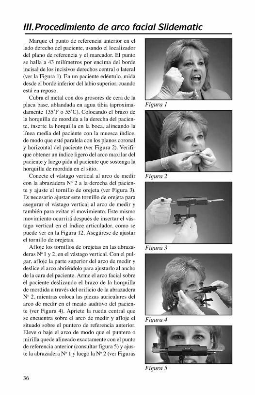
Mark the anterior reference point on the patient’s right side using the Reference Plane Locator and Marker. The point is 43 millimeters above the inci-sal edge of the right central or lateral incisors (see Figure 1). On an endentulous patient, measure up from the lower border of the upper lip when it is in repose.
Cover the metal with two thicknesses of base-plate wax softened in warm water (approximate-ly135˚For55˚C).Withthebiteforkarmtothepatient’s right, place the fork in the mouth, align-ing the patient’s midline with the index notch, so that it is parallel with the patient’s coronal and horizontal planes (see Figure 2). Be certain to obtain a light indexing of the patient’s maxillary arch and then ask the patient to hold the bitefork in place.
Attach the vertical shaft to the measuring bow with the clamp marked #2 on the patient’s right and tighten the finger screw (see Figure 3). It is necessary to tighten this finger screw to secure the vertical shaft to the measuring bow and also to avoid movement. This same movement will occur after inserting the vertical shaft in the articulator index as shown in Figure 12. Be sure to tighten the finger screw.
Loosen the finger screws on the clamps marked #1 and #2 on the vertical shaft. With your thumb, loosen the center wheel on the top of the measuring bow and slide the bow open to accommodate the width of the patient’s face. Assemble the facebow on the patient by sliding the bitefork arm through the hole in clamp #2 as the measuring bow’s earpieces are placed in the patient’s auditory meatus (see Figure 4). Tighten the center wheel on the measuring bow and loosen the finger screw on the anterior refer-ence pointer. Raise or lower the bow so that the pointer or sight aligns precisely with the anterior reference point (see figure 5) and tighten clamp #1, then clamp #2 (see Figures 6 and 7). When tightening clamps #1 and #2, care must be taken
4
III. Slidematic Facebow Procedure
Figure 1
Figure 2
Figure 3
Figure 4
Figure 5

5
Figure 6
Figure 7
Figure 8
Figure 9
Figure 10
not to displace the bow to either side by having the vertical shaft rest on the fingers as shown in Figure 6. The patient’s inter-condylar distance is the measurement indicated on the scale (see Figure 8). Record this measurement.
Loosen the finger screw on the measuring bow, slide the bow open, and remove the entire facebow from the patient.
Detach the measuring bow from the transfer jig by loosening the finger screw (see Figure 9). Having completed the procedures involving the patient, the bitefork assembly (see Figure 10) may be labeled with the patient’s name and set aside while the measuring bow portion can be used with an additional bitefork assembly for the next patient.
Note: The metal bitefork, vertical shaft and earpieces can be sterilized in an autoclave EXCEPTfortheblackfingerscrewsonthe#1 and #2 clamps. Remove the finger screws (and spacers) before autoclaving or use cold sterilization.
Sterilize bitefork before each use.

6
A benefit of using the Denar® Slidematic Facebow is that multiple transfer jigs may be used with only one measuring bow. In some cases the mounting of the maxillary cast can be delegated to the laboratory, involving no loss of accuracy and no period of time without facebow transfer capability in the dental office. The labo-ratory can attach an articulator index to its own Denar® articulator and mount the maxillary cast using only the bitefork assembly from the den-taloffice.Eacharticulator indexpositions thebitefork assembly on any Denar® articulator so that the relationship with the condyles recorded on the patient is accurately reproduced on the articulator.
Denar Articulator IndexReplace the incisal table on the articulator
with the articulator index (see Figure 11). With the numbers on clamps #1 and #2 in the upright position, secure the vertical shaft of the bitefork assembly in the hole of the articulator index. Tighten the finger screw on the front edge of the index (see Figure 12). The incisal pin should set on top of the slide insert on the articulator index (see Figure 13).
Hanau Articulator IndexRemove the mounting plate from the lower
member. Using the lower member thumb screw attach the Hanau index with the transfer assem-bly hole to the front of the articulator. With the numbers on clamps #1 and #2 in the upright position, secure the vertical shaft of the bitefork assembly in the hole of the Hanau index. Tighten the finger screw on the front edge of the index (see Figure 14).
Whip Mix Screw-type IndexRemove the mounting plate from the lower
member. Using the lower member thumb screw attach the Whip Mix screw-type index with the transfer assembly hole to the front of the articu-lator. With the numbers on clamps #1 and #2 in the upright position, secure the vertical shaft of the bitefork assembly in the hole of the Whip Mix screw-type index. Tighten the finger screw on the front edge of the index (see Figure 15).
IV. Mounting Procedure
Figure 11
Figure 12
Figure 14
Figure 15
Figure 13
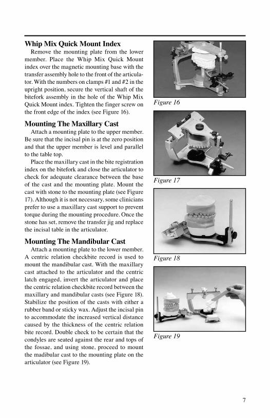
Figure 16
7
Whip Mix Quick Mount IndexRemove the mounting plate from the lower
member. Place the Whip Mix Quick Mount index over the magnetic mounting base with the transfer assembly hole to the front of the articula-tor. With the numbers on clamps #1 and #2 in the upright position, secure the vertical shaft of the bitefork assembly in the hole of the Whip Mix Quick Mount index. Tighten the finger screw on the front edge of the index (see Figure 16).
Mounting The Maxillary CastAttach a mounting plate to the upper member.
Be sure that the incisal pin is at the zero position and that the upper member is level and parallel to the table top.
Place the maxillary cast in the bite registration index on the bitefork and close the articulator to check for adequate clearance between the base of the cast and the mounting plate. Mount the cast with stone to the mounting plate (see Figure 17). Although it is not necessary, some clinicians prefer to use a maxillary cast support to prevent torque during the mounting procedure. Once the stone has set, remove the transfer jig and replace the incisal table in the articulator.
Mounting The Mandibular CastAttach a mounting plate to the lower member.
A centric relation checkbite record is used to mount the mandibular cast. With the maxillary cast attached to the articulator and the centric latch engaged, invert the articulator and place the centric relation checkbite record between the maxillary and mandibular casts (see Figure 18). Stabilize the position of the casts with either a rubber band or sticky wax. Adjust the incisal pin to accommodate the increased vertical distance caused by the thickness of the centric relation bite record. Double check to be certain that the condyles are seated against the rear and tops of the fossae, and using stone, proceed to mount the madibular cast to the mounting plate on the articulator (see Figure 19).
Figure 17
Figure 18
Figure 19

8
The Slidematic uses either a dentulous or edentulous bitefork. The Slidematic Facebow can be used with other articulators and indexes are available for the Hanau™ and Whip Mix® models.
V. Slidematic Accessories
Standard Biteforks Indexes
Standard BiteforksPart No. 200029 Dentulous 200030 Edentulous
Articulator IndexesPart No. 200080 Denar® 200082 Hanau™ 200088 Whip Mix® 200088Q Whip Mix® QuickMount
OtherPart No. 200009-1 Transfer Jig Assembly 200007 Bitefork/Shaft Assembly 101217 Maxillary Cast Support
VI. Reordering
Whip Mix Corporation warrants the Slidematic Facebow to be free from defects in material and/or workmanship for a period of one year. In the event of a defect, please notify the factory in writing of the defect prior to returning the instru-ment. Whip Mix Corporation will, at its option, either repair, replace or issue credit for such defects.
Because Whip Mix Corporation is continually advancing the design of its products and manufacturing methods, it reserves the right to improve, modify or discontinue products at any time, or to change specifications or prices without notice and without incurring obligations.
VII. Warranty
Denar® and Whip Mix® are registered trademarks and Hanau™ is a trademark of Whip Mix Corporation.

I. Entwicklungsgrundlage ................................................... 10II. Vorzüge und Merkmale ................................................... 10III. Slidematic Gesichtsbogen: Verfahren .............................. 12IV. Montageverfahren ............................................................ 14V. Slidematic Zubehör .......................................................... 16VI. Nachbestellung ................................................................. 16VII. Garantie ............................................................................ 16
9
Inhaltsverzeichnis

I. EntwicklungsgrundlageBasierend auf einer gründ-
lichen Analyse der auf dem Markt erhältlichen Gesichtsbögen haben Inge-nieure in Zusammenarbeit mit führenden Ärzten und Ausbildern eine Liste von Kri-terien für die Entwicklung dieses neuenGesichtsbogens zusammengestellt. Der Slidematic Gesichtsbogen soll folgenden Anforderungen entsprechen:
• GenaueinstellbarerOhrbügel,dersichgeradlinig auf der Horizontalen bewegt, so daß er - im Gegensatz zum Zirkeltyp, der von der vertikalen Achse abweicht - verschiedenen Ge sichtsbreiten ange-paßt werden kann.
• EineminimaleAnzahlvonTeilenundFlügelschrauben, damit eine Gesichts-bogen-Registrierung innerhalb einer
sehr kurzen Zeitspanne durchgeführt werden kann.
• Durch die Möglichkeit, den Biß-gabelsatz (ohne den Meßbogen) an das Labor zu senden, wird eine Beschädi-gung des Bogens beim Transport ver-mieden.
• Einfache Montage des Oberkiefer-Modells, da der Meßbogen nicht auf den Artikulator übertragen werden muß.
• DieMöglichkeit,mehrfacheGesichts-bogen-Aufzeichnungen mit äußerst niedrigen Kosten vor zunehmen, da nur ein Meßbogen und verschiedene Bißga-belsätze für einzelne Patienten verwen-det werden.
II. Vorzüge und MerkmaleGesichtsbogen-Transfer
Das Verfahren für den Gesichtsbogen-Transfer bestimmt das Verhältnis zwischen der maxillären Dentition und der horizon-talen Referenzebene, so daß das Oberkie-fer-Modells in der anat omisch richtigen Position in dem Artikulator montiert werden kann. Der Slidematic Gesichtsbo-gen ist ein schneller, leichter und äußerst akkurater Weg zum Übertragen der rich-tigen anatomischen Verhältnisse auf den Artikulator.
Vorzüge und Merkmale• AufgrundseinerPräzisionsherstellung
erlaubt der einmalige, schnell gleiten-de („speed-slide“) Mechanismus einen schnellen und einfachen Zusammenbau des Bogens am Patienten.
• Der rechte und linkeArm desMeß-bogens ist für präzise Bewegung im gleichen Abstand von der Bogenmitte ausgelegt.
• DieSkalaaufdemMeßbogenstelltden interkondylären Ab stand des Pati-enten dar (nicht den Abstand innerhalb des Bogens), so daß Artikulatoren mit diesem Merkmal leicht eingestellt wer-den können.
• DerSlidematicGesichtsbogenkannmitallen Denar® Artikulatoren verwendet werden.ErkannauchmitWhipMix® und Hanau™ Artikulatoren zusammen verwendet werden.
• DerBogenbestimmtdieStellefürdiebeliebig gewählte Scharnierachse mit Hilfe des Referenzpunktes für den äußeren Gehörgang.
• DereingebauteReferenzindikatorori-entiert den Bogen mit der horizontalen Referenzebene.
• Die eingebaute Sehritze kann zumBetrachten des anterioren Referenz-punktes verwendet werden.
10
1
2
3
4
1
2
3
45
6
11
• DerMeßbogensolltenichtwährenddes
Transferverfahrens auf den Artikulator montiert werden. Wenn der Bogen vom Vertikalschaft abgenommen wird, kann er sofort wieder mit den zusätzlichen Transfer Jigs verwendet werden (Ver-tikalschaft, Bißgabelsatz und Artiku-lator-Index). Auf diese Weise können Oberkiefer-Modelle jederzeit montiert werden.
• MiteinemArbeitsschrittwirdderBiß-gabelsatz am Artikulator-Index befe-stigt und das Oberkiefer-Modell am Artikulator montiert.
• AlleFlügelschraubensindvonderVor-derseite aus leicht zugänglich.
• Die Verfahrensschritte können ohneweiteres an die Helferin über geben werden.
Weitere Einzelheiten entnehmen Sie bitte der Denar® Slidematic Gesichtsbogen Tel-leliste #8815-1.
Bißgabel vor jedem Gebrauch sterilisieren.
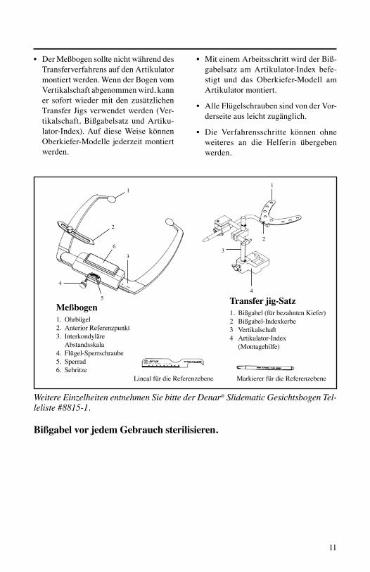
Meßbogen1. Ohrbügel2. Anterior Referenzpunkt3. Interkondyläre
Abstandsskala4. Flügel-Sperrschraube5. Sperrad6. Sehritze
Transfer jig-Satz1. Bißgabel (für bezahnten Kiefer)2 Bißgabel-Indexkerbe3 Vertikalschaft4 Artikulator-Index
(Montagehilfe)
Lineal für die Referenzebene Markierer für die Referenzebene
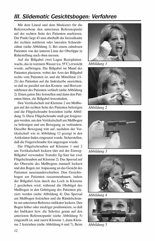
Mit dem Lineal und dem Markierer für die Referenzebene den anterioren Referenzpunkt auf der rechten Seite des Patienten markieren. Der Punkt liegt 43 mm oberhalb der Inzisalkante der rechten mittleren oder lateralen Schneide-zähne (siehe Abbildung 1). Bei einem zahnlosen Patienten von der unteren Linie der Oberlippe in Ruhestellung nach oben messen.
Auf die Bißgabel zwei Lagen Basisplatten-wachs,dasinwarmemWasser(ca.55˚C)erweichtwurde, aufbringen. Die Bißgabel im Mund des Patienten plazieren, wobei der Arm der Bißgabel rechts vom Patienten ist, und die Mittellinie (11-21) des Patienten auf die Indexkerbe ausrichten, so daß sie parallel mit den Kronen- und Horizon-talebenen des Patienten verläuft (siehe Abbildung 2).EinengutenSitzfeststellenunddanndenPati-enten bitten, die Bißgabel festzuhalten.
Den Vertikalschaft mit Klemme 2 am Meßbo-gen auf der rechten Seite des Patienten befestigen und die Flügelschraube festziehen (siehe Abbil-dung 3). Diese Flügelschraube muß gut festgezo-gen werden, um den Vertikalschaft am Meßbogen zu befestigen und um Bewegung zu verhindern. Dieselbe Bewegung tritt auf, nachdem der Ver-tikalschaft wie in Abbildung 12 gezeigt in den Artikulator-Index eingesetzt wurde. Sicherstellen, daß die Fingerschraube fest angezogen wurde.
Die Flügelschrauben auf Klemme 1 und 2 amVertikalschaftlockern(dermitderEinweg-Bißgabel verwendete Transfer Jig-Satz hat zwei Flügelschrauben auf Klemme 2). Das Sperrad auf der Oberseite des Meßbogens manuell lockern und den Bogen zur Anpassung an das Gesicht des Patienten auseinanderschieben. Den Gesichts-bogen am Patienten zusammenbauen, indem der Bißgabel-Arm durch das Loch in Klemme 2 geschoben wird, während die Ohrbügel des Meßbogen in den Gehörgang des Patienten pla-ziert werden (siehe Abbildung 4). Das Sperrad am Meßbogen festziehen und die Rändelschrau-be am anterioren Referenz-indikator lockern. Den Bogen höher oder niedriger positionieren, so daß der Indikator bzw. die Sehritze genau auf den anterioren Referenzpunkt (siehe Abbildung 5) eingestellt ist, und zuerst Klemme 1, dann Klem-me 2 festziehen (siehe Abbildung 6 und 7). Beim
12
III. Slidematic Gesichtsbogen: Verfahren
Abbildung 1
Abbildung 2
Abbildung 3
Abbildung 4
Abbildung 5

13
Befestigen der Klemmen 1 und 2 ist Vorsicht zu üben, so daß der Bogen nicht nach einer Seite hin verschoben wird, indem der Vertikalschaft wie in Abbildung 6 gezeigt auf den Fingern aufliegt. Der interkondyläre Abstand des Patienten ist der auf der Skala angezeigten Messung (siehe Abbil-dung 8). Diese Messung notieren.
Die Flügelschraube am Meßbogen lockern, den Bogen aufschieben und den ganzen Satz vom Gesicht des Patienten abnehmen.
Durch Lockern der Flügelschraube den Meßbo-gen vom Transfer Jig abnehmen (siehe Abbildung 9). Wenn das Verfahren für einen Patienten beendet ist, kann der Bißgabelsatz mit dem Namen des Pati-enten identifiziert (siehe Abbildung 10) und bei-seitegelegt werden. Der Meßbogenteil kann dann mit einem anderen Bißgabelsatz für den nächsten Patienten verwendet werden.
Hinweis: Der Vertikalschaft der Metallbißgabel unddieOhrbügel,JEDOCHNICHTdieschwar-zen Flügel schrauben auf Klemme 1 und 2, kön-nen im Autoklaven sterilisiert werden. Die Flügel schrauben (und Abstandhalter) vor dem Autoklavieren entfernen oder Sterilisation im Kaltverfahren ist durch führen.
Bißgabel vor jedem Gebrauch sterilisieren.
Abbildung 6
Abbildung 7
Abbildung 8
Abbildung 9
Abbildung 10
14
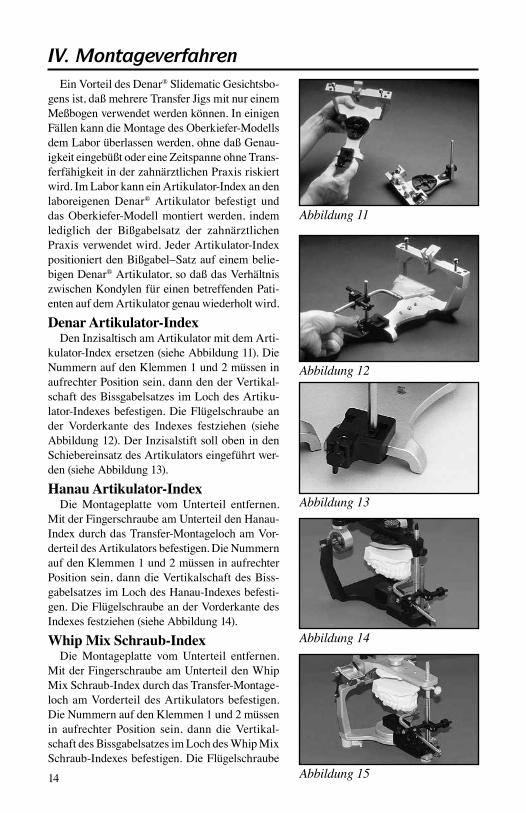
EinVorteildesDenar® Slidematic Gesichtsbo-gens ist, daß mehrere Transfer Jigs mit nur einem Meßbogen verwendet werden können. In einigen Fällen kann die Montage des Oberkiefer-Modells dem Labor überlassen werden, ohne daß Genau-igkeit eingebüßt oder eine Zeitspanne ohne Trans-ferfähigkeit in der zahnärztlichen Praxis riskiert wird. Im Labor kann ein Artikulator-Index an den labor eigenen Denar® Artikulator befestigt und das Oberkiefer-Modell montiert werden, indem lediglich der Bißgabelsatz der zahnärztlichen Praxis verwendet wird. Jeder Artikulator-Index positioniert den Bißgabel–Satz auf einem belie-bigen Denar® Artikulator, so daß das Verhältnis zwischen Kondylen für einen betreffenden Pati-enten auf dem Artikulator genau wiederholt wird.
Denar Artikulator-IndexDen Inzisaltisch am Artikulator mit dem Arti-
kulator-Index ersetzen (siehe Abbildung 11). Die Nummern auf den Klemmen 1 und 2 müssen in aufrechter Position sein, dann den der Vertikal-schaft des Bissgabelsatzes im Loch des Artiku-lator-Indexes befestigen. Die Flügelschraube an der Vorderkante des Indexes festziehen (siehe Abbildung 12). Der Inzisalstift soll oben in den Schiebereinsatz des Artikulators eingeführt wer-den (siehe Abbildung 13).
Hanau Artikulator-IndexDie Montageplatte vom Unterteil entfernen.
Mit der Fingerschraube am Unterteil den Hanau-Index durch das Transfer-Montageloch am Vor-derteil des Artikulators befestigen. Die Nummern auf den Klemmen 1 und 2 müssen in aufrechter Position sein, dann die Vertikalschaft des Biss-gabelsatzes im Loch des Hanau-Indexes befesti-gen. Die Flügelschraube an der Vorderkante des Indexes festziehen (siehe Abbildung 14).
Whip Mix Schraub-IndexDie Montageplatte vom Unterteil entfernen.
Mit der Fingerschraube am Unterteil den Whip Mix Schraub-Index durch das Transfer-Montage-loch am Vorderteil des Artikulators befestigen. Die Nummern auf den Klemmen 1 und 2 müssen in aufrechter Position sein, dann die Vertikal-schaft des Bissgabelsatzes im Loch des Whip Mix Schraub-Indexes befestigen. Die Flügelschraube
IV. Montageverfahren
Abbildung 11
Abbildung 12
Abbildung 13
Abbildung 14
Abbildung 15
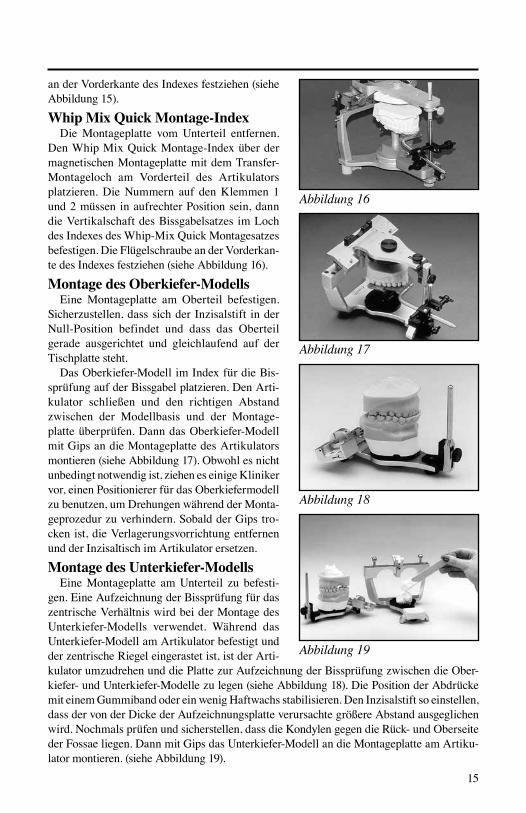
Abbildung 16
15
Abbildung 17
Abbildung 18
Abbildung 19
an der Vorderkante des Indexes festziehen (siehe Abbildung 15).
Whip Mix Quick Montage-IndexDie Montageplatte vom Unterteil entfernen.
Den Whip Mix Quick Montage-Index über der magnetischen Montageplatte mit dem Transfer-Montageloch am Vorderteil des Artikulators platzieren. Die Nummern auf den Klemmen 1 und 2 müssen in aufrechter Position sein, dann die Vertikalschaft des Bissgabelsatzes im Loch des Indexes des Whip-Mix Quick Montagesatzes befestigen. Die Flügelschraube an der Vorderkan-te des Indexes festziehen (siehe Abbildung 16).
Montage des Oberkiefer-ModellsEineMontageplatte am Oberteil befestigen.
Sicherzustellen, dass sich der Inzisalstift in der Null-Position befindet und dass das Oberteil gerade ausgerichtet und gleichlaufend auf der Tischplatte steht.
Das Oberkiefer-Modell im Index für die Bis-sprüfung auf der Bissgabel platzieren. Den Arti-kulator schließen und den richtigen Abstand zwischen der Modellbasis und der Montage-platte überprüfen. Dann das Oberkiefer-Modell mit Gips an die Montageplatte des Artikulators montieren (siehe Abbildung 17). Obwohl es nicht unbedingt notwendig ist, ziehen es einige Kliniker vor, einen Positionierer für das Oberkiefermodell zu benutzen, um Drehungen während der Monta-geprozedur zu verhindern. Sobald der Gips tro-cken ist, die Verlagerungsvorrichtung entfernen und der Inzisaltisch im Artikulator ersetzen.
Montage des Unterkiefer-ModellsEineMontageplatte amUnterteil zu befesti-
gen.EineAufzeichnungderBissprüfungfürdaszentrische Verhältnis wird bei der Montage des Unterkiefer-Modells verwendet. Während das Unterkiefer-Modell am Artikulator befestigt und der zentrische Riegel eingerastet ist, ist der Arti-kulator umzudrehen und die Platte zur Aufzeichnung der Bissprüfung zwischen die Ober-kiefer- und Unterkiefer-Modelle zu legen (siehe Abbildung 18). Die Position der Abdrücke mit einem Gummiband oder ein wenig Haftwachs stabilisieren. Den Inzisalstift so einstellen, dass der von der Dicke der Aufzeichnungsplatte verursachte größere Abstand ausgeglichen wird. Nochmals prüfen und sicherstellen, dass die Kondylen gegen die Rück- und Oberseite der Fossae liegen. Dann mit Gips das Unterkiefer-Modell an die Montageplatte am Artiku-lator montieren. (siehe Abbildung 19).

16
Slidematic verwendet entweder Bißgabeln für Patienten mit oder ohne Zähnen. Der Slidematic Gesichtsbogen kann mit anderen Artikulatoren verwendet werden. Indexe für Hanau™ und Whip Mix® stehen zur Verfügung.
V. Slidematic Zubehör
Standardmäßige BitßgabelnBestell Nr. 200029 Bezahnt 200030 Zahnlos
Artikulator-IndexeBestell Nr. 200080 Denar® 200082 Hanau™ 200088 Whip Mix® 200088Q Whip Mix® QuickMount
Sonstiges ZubehörBestell Nr. 200009-1 Transfer Jig-Satz 200007 Bißgabel-/Schaft Satz 101217 Bißgabelstütze
VI. Nachbestellung
Whip Mix Corporation garantiert für ein Jahr, daß der Slidematic Gesichtsbo-gen frei von Werkstoff- und/oder Verarbei-tungsmängeln ist. Bei Mängeln bitten wir, das Werk schrift lich davon in Kenntnis zu setzen, ehe das Instrument zurückgegeben wird. Whip Mix Corporation wird im eige-nenErmessenderartigeMängelentwederreparieren, das Instrument ersetzen oder eine Gutschrift ausstellen.
Whip Mix Corporation ist ständig um Fortschritte im Design ihrer Produkte und Herstellungsmethoden bemüht und behält sich das Recht vor, diese Produkte jederzeit zu verbessern, modifizieren oder nicht mehr herzustellen, sowie die Spezifikationen oder Preise ohne vorherige Bekanntgabe und ohne irgend welche Verpflichtungen zu ändern.
VII. Garantie
Standardmäßige Bißgabeln Indexe
Denar® und Whip Mix® sowie sind eingetragene Warenzeichen und Hanau™ ist ein Waren-zeichen von Whip Mix Corporation.

I Logique du développement ............................................. 18II. Avantages et caractéristiques ........................................... 18III. Procédures d’utilisation du mesureur facial Slidematic ......................................................................... 20IV. Procédure d’assemblage .................................................. 22V. Accessoires pour le Slidematic .........................................24VI. Numéros de commandes ...................................................24VII. Garantie .............................................................................24
17
Table des matières

I. Logique du développementSur la base d’une analyse en profondeur
de tous les mesureurs faciaux disponibles sur le marché, et conjointement avec plu-sieurs éminents cliniciens et éducateurs, les ingénieurs ont établi une liste de cri-tères pour le développement de ce nou-veau mesureur facial. Le mesureur facial Slidematic a été créé afin de satisfaire les exigences suivantes:
• Unarc demesureauriculaireprécis,mobile exclusivement dans le plan horizontal afin de s’adapter aux diffé-rentes largeurs faciales, et ce contraire-ment aux appareils de type “compas”, mobiles dans le plan vertical.
• Un nombre minimal de pièces ajus-tables et de vis permet l’enregistrement des dimensions faciales en un temps réduit.
• La capacité de pouvoir désolidariserl’arc de mesure auriculaire de la four-chette dentaire permet l’envoi de cette dernière (séparément) au laboratoire. Ceci permet d’éviter les dommages potentiels causés à l’arc de mesure lors de son transit.
• Facilitédemontagedumoulagemaxil-laire sans avoir à transférer l’arc de mesure auriculaire sur l’articulateur.
• Lecoûtdesmesuresfacialesestréduitgrâce à l’utilisation d’un seul arc de mesure sur lequel s’adapte la fourchette dentaire de chaque patient.
Capture des dimensions facialesLa procédure de capture des dimen-
sions faciales définit la dentition maxil-laire par rapport au plan horizontal de référence, ce qui permet d’obtenir un moulage maxillaire sur l’articulateur dans la position anatomique correcte. L’arc de mesure facial Slidematic permet ainsi le transfert rapide, facile et extrêmement précis des données anatomiques sur l’arti-culateur.
Avantages et caractéristiques.• Laprécisiondefabricationdelastruc-
ture coulissante facilite et accélère l’assemblage de l’arc de mesure sur le patient.
• Lesbranchesdroitesetgauchesdel’arcde mesure se déploient à égale distance du centre de l’arc.
• L’échelle sur l’arc de mesure repré-sente la distance intercondylaire du patient (et non pas l’ouverture de l’arc) afin de faciliter l’ajustement des articu-lateurs prenant en compte cette mise au point.
• L’arcdemesurefacialSlidematicpeutêtre utilisé sur tous les articulateurs de marque Denar®. Il s’adapte aussi sur les articulateurs Whip Mix® et Hanau™.
• L’arc de mesure utilise le trou audi-tif comme point de référence afin de déterminer la localisation arbitraire de l’axe charnière de la mâchoire.
• Lepointeurderéférenceintégréalignel’arc de mesure dans la plan horizontal de référence.
• Leviseurintégrépermetdevisualiserle point de référence antérieur.
18
II. Avantages et caractéristiques
1
2
3
4
1
2
3
45
6
19
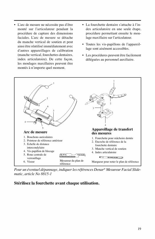
• L’arcdemesurenenécessitepasd’être
monté sur l’articulateur pendant la procédure de capture des dimensions faciales. L’arc de mesure se détache du manche vertical de soutien et peut ainsi être réutilisé immédiatement avec d’autres appareillages de calibration (manche vertical, fourchettes dentaires, index articulatoire). De cette façon, les moulages maxillaires peuvent être montés à n’importe quel moment.
• Lafourchettedentaires’attacheàl’in-dex articulatoire en une seule étape, procédure permettant ensuite le mou-lage maxillaire sur l’articulateur.
• Toutes lesvis-papillonsde l’appareil-lage sont aisément accessibles.
• Lesprocédurespeuventêtrefacilementdéléguées au personnel auxiliaire.
Pour un éventuel dépannage, indiquer les références Denar® Mesureur Facial Slide-matic, article No 8815-1
Stérilisez la fourchette avant chaque utilisation.
Arc de mesure1. Bouchons auriculaires2. Pointeur de référence antérieur3. Echellededistance
intercondylaire4. Vis-papillon de blocage5. Roue centrale de
verrouillage6. Viseur
Appareillage de transfert des mesures1. Fourchette pour mâchoire dentée2. Encochederéférencedela
fourchette dentaire3. Manche vertical de soutien4. Index articulatoire
Mesureur du plan de référence
Marqueur pour noter le plan de référence
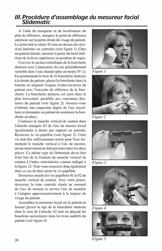
A l’aide du marqueur et du localisateur du plan de référence, marquez le point de référence antérieur sur la partie droite du visage du patient. Le point doit se situer 43 mm au-dessus des inci-sives latérales ou centrales (voir figure 1). Chez un patient édenté, mesurez à partir du bord infé-rieur de la lèvre supérieure en position de repos.
Couvrez la surface métallique de la fourchette dentaire avec 2 épaisseurs de cire préalablement ramolliedansl’eauchaude(plusoumoins55˚c).Enpositionnantlebrasdelafourchettedentaireà la droite du patient, placez la fourchette dans la bouche en alignant l’espace d’inter-incisives du patient avec l’encoche de référence de la four-chette. La fourchette dentaire est ainsi dans le plan horizontal, parallèle aux couronnes den-taires du patient (voir figure 2). Assurez-vous d’obtenir une empreinte légère de l’arc maxil-laire et demandez au patient de maintenir la four-chette en place.
Coulissez le manche vertical de soutien dans l’attache marquée #2 de l’arc de mesure facial (positionnée à droite par rapport au patient). Resserrez la vis-papillon (voir figure 3). Cette vis doit être suffisamment serrée pour fixer fer-mement le manche vertical à l’arc de mesure, aucun mouvement ne doit persister entre les deux pièces. Ce même type de flottement devra être évité lors de la fixation du manche vertical de soutien à l’index articulatoire comme indiqué à la figure 12. Vous vous assurerez donc également dans ce cas de bien serrer la vis-papillon.
Desserrez ensuite les vis-papillons #1 et #2 du manche vertical de soutien. Avec votre pouce, desserrez la roue centrale située au sommet de l’arc de mesure et ouvrez l’arc de manière à l’adapter approximativement à la largeur du visage du patient.
Assemblez le mesureur facial sur le patient en faisant glisser la tige de la fourchette dentaire dans le trou de l’attache #2 tout en plaçant les bouchons auriculaires dans les trous auditifs du patient (voir figure 4).
20
III. Procédure d’assemblage du mesureur facial Slidematic
Figure 1
Figure 2
Figure 3
Figure 4
Figure 5
21
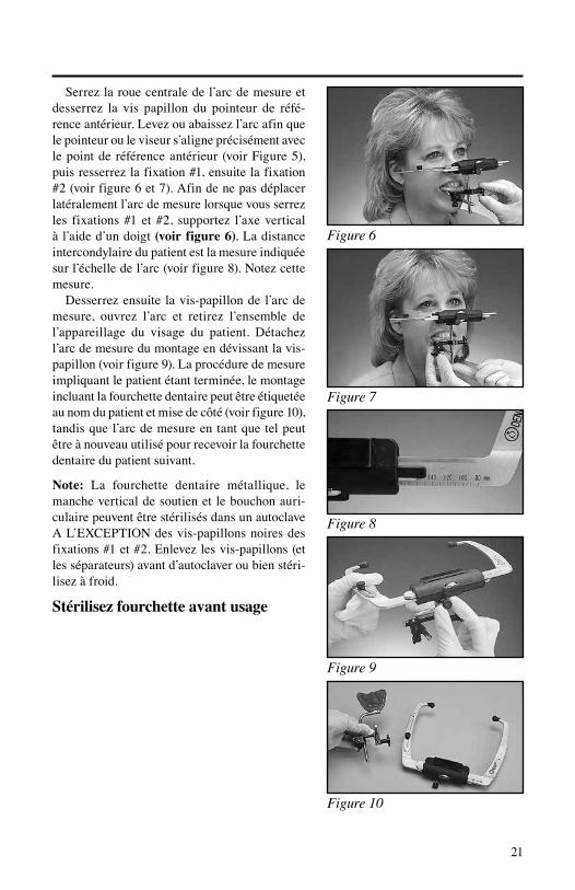
Serrez la roue centrale de l’arc de mesure et desserrez la vis papillon du pointeur de réfé-rence antérieur. Levez ou abaissez l’arc afin que le pointeur ou le viseur s’aligne précisément avec le point de référence antérieur (voir Figure 5), puis resserrez la fixation #1, ensuite la fixation #2 (voir figure 6 et 7). Afin de ne pas déplacer latéralement l’arc de mesure lorsque vous serrez les fixations #1 et #2, supportez l’axe vertical à l’aide d’un doigt (voir figure 6). La distance intercondylaire du patient est la mesure indiquée sur l’échelle de l’arc (voir figure 8). Notez cette mesure.
Desserrez ensuite la vis-papillon de l’arc de mesure, ouvrez l’arc et retirez l’ensemble de l’appareillage du visage du patient. Détachez l’arc de mesure du montage en dévissant la vis-papillon (voir figure 9). La procédure de mesure impliquant le patient étant terminée, le montage incluant la fourchette dentaire peut être étiquetée au nom du patient et mise de côté (voir figure 10), tandis que l’arc de mesure en tant que tel peut être à nouveau utilisé pour recevoir la fourchette dentaire du patient suivant.
Note: La fourchette dentaire métallique, le manche vertical de soutien et le bouchon auri-culaire peuvent être stérilisés dans un autoclave AL’EXCEPTIONdesvis-papillonsnoiresdesfixations#1et#2.Enlevezlesvis-papillons(etles séparateurs) avant d’autoclaver ou bien stéri-lisez à froid.
Stérilisez fourchette avant usage
Figure 6
Figure 7
Figure 8
Figure 9
Figure 10
22
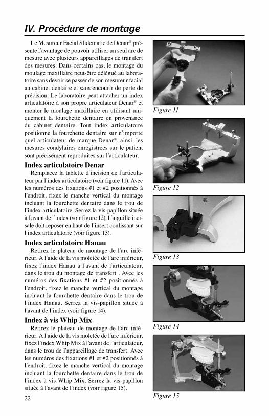
Le Mesureur Facial Slidematic de Denar® pré-sente l’avantage de pouvoir utiliser un seul arc de mesure avec plusieurs appareillages de transfert des mesures. Dans certains cas, le montage du moulage maxillaire peut-être délégué au labora-toire sans devoir se passer de son mesureur facial au cabinet dentaire et sans encourir de perte de précision. Le laboratoire peut attacher un index articulatoire à son propre articulateur Denar® et monter le moulage maxillaire en utilisant uni-quement la fourchette dentaire en provenance du cabinet dentaire. Tout index articulatoire positionne la fourchette dentaire sur n’importe quel articulateur de marque Denar®, ainsi, les mesures condylaires enregistrées sur le patient sont précisément reproduites sur l’articulateur.
Index articulatoire DenarRemplacez la tablette d’incision de l’articula-
teur par l’index articulatoire (voir figure 11). Avec les numéros des fixations #1 et #2 positionnés à l’endroit, fixez le manche vertical du montage incluant la fourchette dentaire dans le trou de l’index articulatoire. Serrez la vis-papillon située à l’avant de l’index (voir figure 12). L’aiguille inci-sale doit reposer en haut de l’insert coulissant sur l’index articulatoire (voir figure 13).
Index articulatoire HanauRetirez le plateau de montage de l’arc infé-
rieur. A l’aide de la vis moletée de l’arc inférieur, fixez l’index Hanau à l’avant de l’articulateur, dans le trou du montage de transfert . Avec les numéros des fixations #1 et #2 positionnés à l’endroit, fixez le manche vertical du montage incluant la fourchette dentaire dans le trou de l’index Hanau. Serrez la vis-papillon située à l’avant de l’index (voir figure 14).
Index à vis Whip MixRetirez le plateau de montage de l’arc infé-
rieur. A l’aide de la vis moletée de l’arc inférieur, fixez l’index Whip Mix à l’avant de l’articulateur, dans le trou de l’appareillage de transfert. Avec les numéros des fixations #1 et #2 positionnés à l’endroit, fixez le manche vertical du montage incluant la fourchette dentaire dans le trou de l’index à vis Whip Mix. Serrez la vis-papillon située à l’avant de l’index (voir figure 15).
IV. Procédure de montage
Figure 11
Figure 12
Figure 14
Figure 15
Figure 13
23
Index à fixation rapide Whip MixRetirez le plateau de montage de l’arc inférieur.
Placez l’index à fixation rapide Whip Mix sur le socle magnétique, dans le trou de l’appareillage de transfert à l’avant de l’articulateur. Avec les numé-ros des fixations #1 et #2 positionnés à l’endroit, fixez le manche vertical du montage incluant la fourchette dentaire dans le trou de l’index à fixation rapide Whip Mix. Serrez la vis-papillon située à l’avant de l’index (voir figure 16).
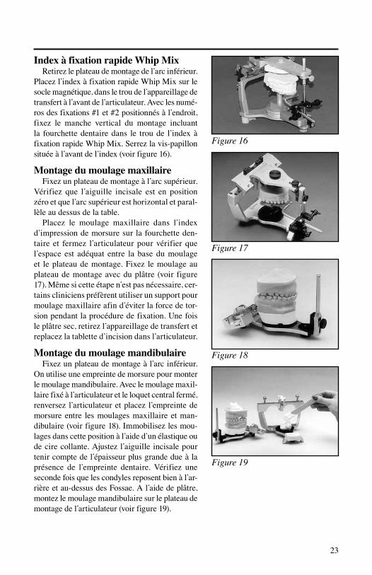
Montage du moulage maxillaireFixez un plateau de montage à l’arc supérieur.
Vérifiez que l’aiguille incisale est en position zéro et que l’arc supérieur est horizontal et paral-lèle au dessus de la table.
Placez le moulage maxillaire dans l’index d’impression de morsure sur la fourchette den-taire et fermez l’articulateur pour vérifier que l’espace est adéquat entre la base du moulage et le plateau de montage. Fixez le moulage au plateau de montage avec du plâtre (voir figure 17). Même si cette étape n’est pas nécessaire, cer-tains cliniciens préfèrent utiliser un support pour moulage maxillaire afin d’éviter la force de tor-sion pendant la procédure de fixation. Une fois le plâtre sec, retirez l’appareillage de transfert et replacez la tablette d’incision dans l’articulateur.
Montage du moulage mandibulaireFixez un plateau de montage à l’arc inférieur.
On utilise une empreinte de morsure pour monter le moulage mandibulaire. Avec le moulage maxil-laire fixé à l’articulateur et le loquet central fermé, renversez l’articulateur et placez l’empreinte de morsure entre les moulages maxillaire et man-dibulaire (voir figure 18). Immobilisez les mou-lages dans cette position à l’aide d’un élastique ou de cire collante. Ajustez l’aiguille incisale pour tenir compte de l’épaisseur plus grande due à la présence de l’empreinte dentaire. Vérifiez une seconde fois que les condyles reposent bien à l’ar-rière et au-dessus des Fossae. A l’aide de plâtre, montez le moulage mandibulaire sur le plateau de montage de l’articulateur (voir figure 19).
Figure 16
Figure 17
Figure 18
Figure 19
24
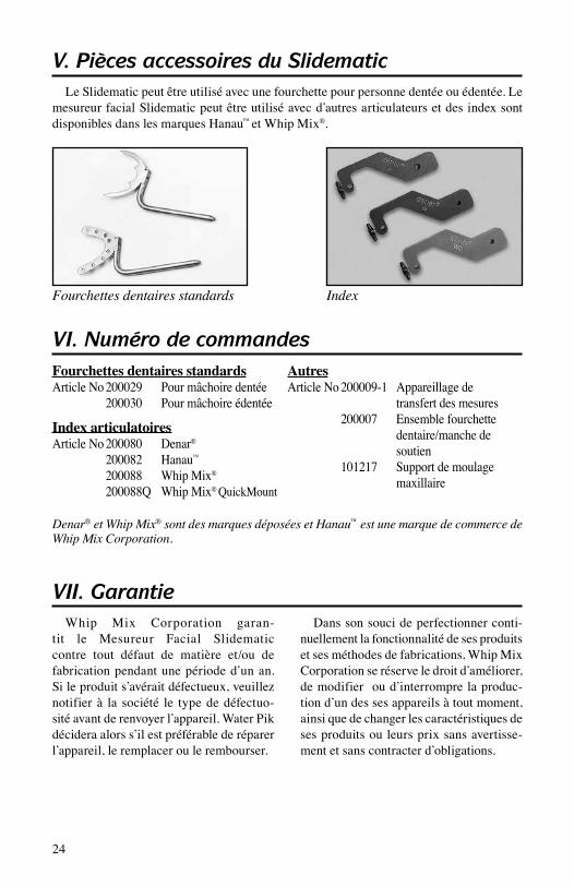
Le Slidematic peut être utilisé avec une fourchette pour personne dentée ou édentée. Le mesureur facial Slidematic peut être utilisé avec d’autres articulateurs et des index sont disponibles dans les marques Hanau™ et Whip Mix®.
V. Pièces accessoires du Slidematic
Fourchettes dentaires standardsArticle No 200029 Pour mâchoire dentée 200030 Pour mâchoire édentée
Index articulatoiresArticle No 200080 Denar® 200082 Hanau™ 200088 Whip Mix®
200088Q Whip Mix® QuickMount
AutresArticle No 200009-1 Appareillage de transfert des mesures 200007 Ensemblefourchette dentaire/manche de soutien 101217 Support de moulage maxillaire
VI. Numéro de commandes
Whip Mix Corporation garan-tit le Mesureur Facial Slidematic contre tout défaut de matière et/ou de fabrication pendant une période d’un an. Si le produit s’avérait défectueux, veuillez notifier à la société le type de défectuo-sité avant de renvoyer l’appareil. Water Pik décidera alors s’il est préférable de réparer l’appareil, le remplacer ou le rembourser.
Dans son souci de perfectionner conti-nuellement la fonctionnalité de ses produits et ses méthodes de fabrications, Whip Mix Corporation se réserve le droit d’améliorer, de modifier ou d’interrompre la produc-tion d’un des ses appareils à tout moment, ainsi que de changer les caractéristiques de ses produits ou leurs prix sans avertisse-ment et sans contracter d’obligations.
VII. Garantie
Fourchettes dentaires standards Index
Denar® et Whip Mix® sont des marques déposées et Hanau™ est une marque de commerce de Whip Mix Corporation.

I. Motivazione dello sviluppo ............................................. 26II. Benefici e principali caratteristiche ................................. 26III. Procedure per l’Arco Facciale Slidematic ....................... 28IV. Procedure di montaggio ................................................... 30V. Accessori dello Slidematic .............................................. 32VI. Riordino ............................................................................ 32VII. Garanzia ........................................................................... 32
25
Tavola dei Contenuti
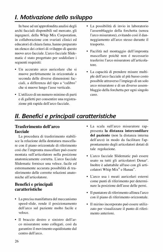
I. Motivazione dello sviluppoIn base ad un’approfondita analisi degli
archi facciali disponibili sul mercato, gli ingegneri, della Whip Mix Corporation, in collaborazione con svariati clinici ed educatori di chiara fama, hanno preparato un elenco dei criteri di sviluppo di questo nuovo arco facciale. L'arco facciale Slide-matic é stato progettato per soddisfare i seguenti requisiti:
• Un accurato arco auricolare che simuove perfettamente in orizzontale a seconda delle diverse dimensioni fac-ciali, a differenza del tipo a “calibro” che si muove lungo l’asse verticale.
• L’utilizzodiunnumerominimodipartie di galletti per consentire una registra-zione più rapida dell’arco facciale.
• La possibilità di invio in laboratoriol’assemblaggio della forchetta (senza l’arco misuratore), evitando così il dan-neggiamento all’arco stesso durante il trasporto.
• Facilità nel montaggio dell’improntamascellare poichè non é necessario trasferire l’arco misuratore all’articola-tore.
• Lacapacitàdiprenderemisuremulti-ple dell’arco facciale al più basso costo possibile attraverso l’impiego di un solo arco misuratore e di un diverso assem-blaggio della forchetta per ogni singolo caso.
II. Benefici e principali caratteristiche
Trasferimento dell’arco facciale
La procedura di trasferimento stabili-sce la relazione della dentatura mascella-re con il piano orizzontale di riferimento così che l’impronta mascellare può essere montata sull’articolatore nella posizione anatomicamente corretta. L’arco facciale Slidematic fornisce una veloce, facile ed estremamente accurata possibilità di tra-sferimento delle corrette relazioni anato-miche all’articolatore.
Benefici e principali caratteristiche
• Laprecisamanifatturadelmeccanismospeed-slide, rende il posizionamento dell’arco sul paziente molto facile e veloce.
• Il braccio destro e sinistro dell’ar-co misuratore sono collegati, così da garantire il movimento equidistante dal centro dell’arco.
• La scala sull’arco misuratore rap-presenta la distanza intercondilare del paziente (non la distanza interna dell’arco) in modo da facilitare l'ap-prontamento degli articolatori dotati di tale regolazione.
• L’arco faccialeSlidematic può essereusato su tutti gli articolatori Denar®. Inoltre è adattabile all'uso con gli arti-colatori Whip Mix® e Hanau™.
• L’arco usa i meati auricolari esternicome punti di riferimento per determi-nare la posizione dell’asse delle perni.
• Ilpuntatorediriferimentoallineal’arcocon il piano di riferimento orizzontale.
• Ilmirinoincorporatopuòessereutiliz-zato per visualizzare il punto di riferi-mento anteriore.
26
1
2
3
4
1
2
3
45
6
27
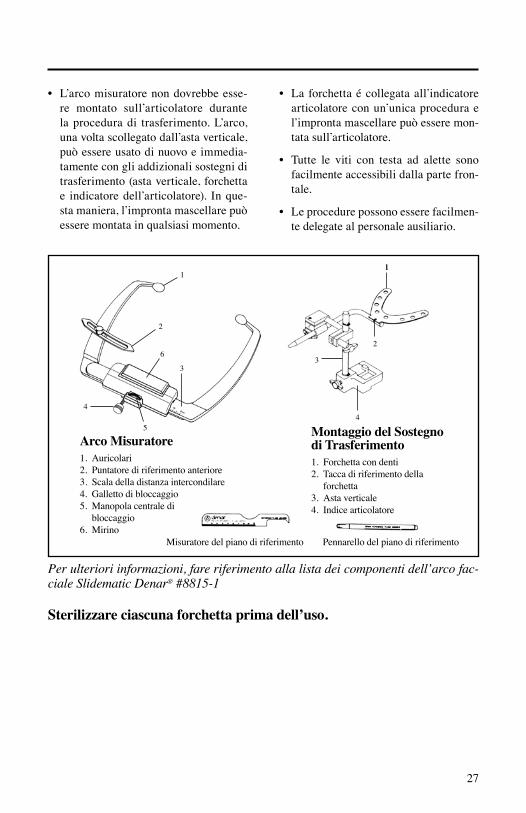
• L’arcomisuratorenondovrebbeesse-re montato sull’articolatore durante la procedura di trasferimento. L’arco, una volta scollegato dall’asta verticale, può essere usato di nuovo e immedia-tamente con gli addizionali sostegni di trasferimento (asta verticale, forchetta e indicatore dell’articolatore). In que-sta maniera, l’impronta mascellare può essere montata in qualsiasi momento.
• La forchettaécollegataall’indicatorearticolatore con un’unica procedura e l’impronta mascellare può essere mon-tata sull’articolatore.
• Tutte le viti con testa ad alette sonofacilmente accessibili dalla parte fron-tale.
• Leprocedurepossonoesserefacilmen-te delegate al personale ausiliario.
Per ulteriori informazioni, fare riferimento alla lista dei componenti dell’arco fac-ciale Slidematic Denar® #8815-1
Sterilizzare ciascuna forchetta prima dell’uso.
1
Arco Misuratore1. Auricolari2. Puntatore di riferimento anteriore3. Scala della distanza intercondilare4. Galletto di bloccaggio 5. Manopola centrale di
bloccaggio6. Mirino
Montaggio del Sostegno di Trasferimento1. Forchetta con denti2. Tacca di riferimento della
forchetta3. Asta verticale4. Indice articolatore
Misuratore del piano di riferimento Pennarello del piano di riferimento

Segnare il punto di riferimento anteriore sul lato destro del paziente usando il misuratore del piano di riferimento e il pennarello. Il punto si trova a 43 millimetri sopra il bordo degli incisivi centrali destri o laterali (vedi Figura 1). Su un paziente senza denti, prendere la misura a partire dal bordo inferiore del labbro superiore quando questo é a riposo.
Coprire il metallo con due spessori piatti di cera ammorbidita in acqua calda (appros-simativamente 135˚F o 55˚C). Con il brac-cio della forchetta alla destra del paziente, posizionare la forchetta nella bocca, alline-ando la linea mediana del paziente con la tac-ca di riferimento, cosí da essere parallelo ai piani coronale e orizzontale (vedi Figura 2). Accertarsi di ottenere una leggera indicazio-ne dell’arco mascellare del paziente e chieder-gli quindi di tenere la forchetta fermo dove si trova.
Collegare l’asta verticale all’arco misurato-re con il morsetto segnato #2 sulla destra del paziente e stringere la vite con testa ad alette (vedi Figura 3). ). Il serraggio di tale galletto è indispensabile per bloccare l’asta verticale sull’arco misuratore evitandone il movimento. Questo stesso movimento si verificherà dopo l’inserimento dell’asta verticale nell’indice arti-colatore, come illustrato nelle figura 12. Assicu-rarsi di stringere la vite con testa ad alette.
Allentare i galletti dei morsetti #1 e #2 sull’a-sta verticale. Allentare con il pollice la manopola centrale di bloccaggio posta sul alto superiore dell’arco misuratore e far scorrere l’arco aper-to in modo da regolarlo in funzione della lar-ghezza del viso del paziente. Assemblare l’arco facciale sul paziente facendo scivolare il braccio della forchetta attraverso il foro del morsetto #2, posizionando gli auricolari dell’arco misuratore all’interno dei canali auditivi del paziente (vedi Figura 4). Serrare la manopola centrale di bloc-caggio dell’arco misuratore e allentare il galletto del puntatore di riferimento anteriore. Allentare
28
III. Procedure per l’arco facciale Slidematic
Figura 1
Figura 2
Figura 3
Figura 4
Figura 5
29
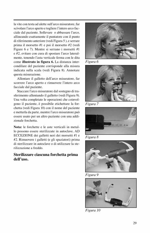
la vite con testa ad alette sull’arco misuratore, far scivolare l’arco aperto e togliere l’intero arco fac-ciale dal paziente. Sollevare o abbassare l’arco, allineando esattamente il puntatore con il punto di riferimento anteriore (vedi Figura 5 ), e serrare prima il morsetto #1 e poi il morsetto #2 (vedi Figure 6 e 7). Mentre si serrano i morsetti #1 e #2, evitare con cura di spostare l’arco lateral-mente, tenendo l’asta verticale ferma con le dita come illustrato in figura 6. La distanza inter-condilare del paziente corrisponde alla misura indicata sulla scala (vedi Figura 8). Annotare questa misurazione.
Allentare il galletto dell’arco misuratore, far scorrere l’arco aperto e rimuovere l’intero arco facciale dal paziente.
Staccare l’arco misuratore dal sostegno di tra-sferimento allentando il galletto (vedi Figura 9). Una volta completate le operazioni che coinvol-gono il paziente, è possibile etichettare la for-chetta (vedi Figura 10) con il nome del paziente e metterla da parte, mentre l’arco misuratore può essere usato per un altro paziente con una addi-zionale forchetta.
Nota: le forchette e le aste verticali in metal-lo possono essere sterilizzate in autoclave, AD ECCEZIONEdeigallettinerideimorsetti#1e#2. Rimuovere i galletti (e gli spaziatori) prima di sterilizzare in autoclave o di utilizzare la ste-rilizzazione a freddo.
Sterilizzare ciascuna forchetta prima dell’uso.
Figura 6
Figura 7
Figura 8
Figura 9
Figura 10

30
Uno dei vantaggi dell'uso dell’arco facciale Denar® Slidematic consiste nell'impiego di più di un sostegno di trasferimento con lo stesso arco misuratore. In alcuni casi, il montaggio dell’im-pronta mascellare può essere affidato al labora-torio, senza alcuna perdita di precisione, permet-tendo di continuare a utilizzare l’arco facciale presso lo studio dentistico. Il laboratorio può collegare un indice articolatore al proprio arti-colatore Denar® e montare l’impronta mascellare usando soltanto la forchetta inviata dallo studio dentistico. Ogni indice articolatore posiziona la forchetta su qualunque articolatore Denar®, riproducendo accuratamente sull’articolatore la relazione con i condili misurati sul paziente
Indice articolatore DenarSostituire la tavola d’incisione sull’articolatore
con l’indice articolatore (vedi Figura 11). Con i numeri nei morsetti 1 e 2 in posizione verticale, bloccare l’asta verticale della forchetta nel foro dell’indice articolatore. Stringere la vite con testa ad alette sul bordo frontale dell’indice (vedi Figu-ra 12). L’asta incisale va collocata sopra l’inserto mobile sull’indice articolatore (vedi figura 13).
Indice articolatore Hanau Rimuovere la piastra di montaggio dall’ar-
co inferiore. Usando la vite ad alette dell’arco inferiore attaccare l’indice Hanau con il foro di montaggio di trasferimento nella parte frontale dell’articolatore. Con i numeri nei morsetti 1 e 2 in posizione verticale, bloccare l’asta verticale della forchetta nel foro dell’indice Hanau. Strin-gere la vite con testa ad alette sul bordo frontale dell’indice (vedi Figura 14).
Indice a vite Whip Mix Rimuovere la piastra di montaggio dall’arco
inferiore. Usando la vite ad alette dell’arco infe-riore attaccare l’indice a vite Whip Mix con il foro di montaggio di trasferimento nella parte frontale dell’articolatore. Con i numeri nei mor-setti 1 e 2 in posizione verticale, bloccare l’asta verticale della forchetta nel foro dell’indice a vite Whip Mix. Stringere la vite con testa ad alette sul bordo frontale dell’indice (vedi Figura 15).
IV. Procedure di montaggio
Figura 11
Figura 12
Figura 14
Figura 15
Figura 13
31
Figura 16
Figura 17
Figura 18
Figura 19
Indice a montaggio rapido Whip Mix Rimuovere la piastra di montaggio dall’arco
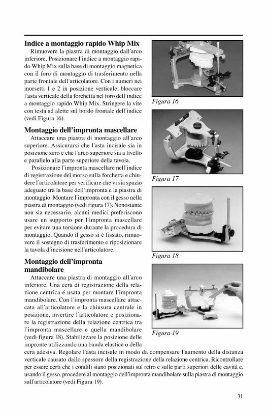
inferiore. Posizionare l’indice a montaggio rapi-do Whip Mix sulla base di montaggio magnetica con il foro di montaggio di trasferimento nella parte frontale dell’articolatore. Con i numeri nei morsetti 1 e 2 in posizione verticale, bloccare l’asta verticale della forchetta nel foro dell’indice a montaggio rapido Whip Mix. Stringere la vite con testa ad alette sul bordo frontale dell’indice (vedi Figura 16).
Montaggio dell’impronta mascellare Attaccare una piastra di montaggio all’arco
superiore. Assicurarsi che l’asta incisale sia in posizione zero e che l’arco superiore sia a livello e parallelo alla parte superiore della tavola.
Posizionare l’impronta mascellare nell’indice di registrazione del morso sulla forchetta e chiu-dere l’articolatore per verificare che vi sia spazio adeguato tra la base dell’impronta e la piastra di montaggio. Montare l’impronta con il gesso nella piastra di montaggio (vedi figura 17). Nonostante non sia necessario, alcuni medici preferiscono usare un supporto per l’impronta mascellare per evitare una torsione durante la procedura di montaggio. Quando il gesso si è fissato, rimuo-vere il sostegno di trasferimento e riposizionare la tavola d’incisione nell’articolatore.
Montaggio dell’impronta mandibolare
Attaccare una piastra di montaggio all’arco inferiore. Una cera di registrazione della rela-zione centrica é usata per montare l’impronta mandibolare. Con l’impronta mascellare attac-cata all’articolatore e la chiusura centrale in posizione, invertire l’articolatore e posiziona-re la registrazione della relazione centrica tra l’impronta mascellare e quella mandibolare (vedi figura 18). Stabilizzare la posizione delle impronte utilizzando una banda elastica o della cera adesiva. Regolare l’asta incisale in modo da compensare l’aumento della distanza verticale causato dallo spessore della registrazione della relazione centrica. Ricontrollare per essere certi che i condili siano posizionati sul retro e sulle parti superiori delle cavità e, usando il gesso, procedere al montaggio dell’impronta mandibolare sulla piastra di montaggio sull’articolatore (vedi Figura 19).

32
Lo Slidematic utilizza forchette sia per pazienti con denti naturali che per pazienti eden-tuli. L’arco facciale Slidematic può essere usato con altri articolatori e sono disponibili indicatori per gli articolatori Hanau™ e Whip Mix®.
V. Accessori della Slidematic
Forchetta standardParte No 200029 Con denti 200030 Senza denti
Indicatori degli articolatoriParte No 200080 Denar® 200082 Hanau™ 200088 Whip Mix®
200088Q Whip Mix® QuickMount
AltriParte No 200009-1 Montaggio del sos tegno di trasferimento 200007 Forchetta/Asta 101217 Supporto dell’im- pronta mascellare
VI. Riordino
La Whip Mix Corporation garantisce l’arco facciale Slidematic come esente da difetti nei materiali e/o nella manifattura per un periodo di un anno. Nel caso di un difetto, si prega di comunicarlo alla socie-ta’ descrivendo il difetto per iscritto, prima di restituire lo strumento. Whip Mix Cor-poration, a sua scelta, riparerà, sostituirà, rifonderà per tale difetto.
Poichè Whip Mix Corporation aggiorna continuamente il progetto dei suoi prodotti cosí come i metodi di produzione, essa si riserva il diritto di migliorare, modificare o non produrre più i suoi prodotti in qua-lunque momento, o anche di cambiare le specifiche o i prezzi senza notificarlo e senza incorrere in alcun obbligo.
VII. Garanzia
Forchetta standard Indicatori
Denar® e Whip Mix® sono marchi registrati e Hanau™ è un marchio di fabbrica di Whip Mix Corporation.

I. Razones para el desarrollo ............................................... 34II. Beneficios y atributos ...................................................... 34III. Procedimiento de arco facial Slidematic ......................... 36IV. Procedimiento de montaje ............................................... 38V. Accesorios Slidematic ...................................................... 40VI. Pedidos ............................................................................. 40VII. Garantía ............................................................................ 40
33
Índice General
I. Razones para el desarrolloBasándose en un profundo análisis de
todos los arcos faciales del mercado, los ingenieros en combinación con varios téc-nicos y educadores importantes, prepara-ron la lista de criterios para el desarrollo deestenuevoarcofacial.ElarcofacialSlidematic se diseño para que cumpliese con los siguientes requisitos:
• Unarcoauricularquesemueveenfor-ma recta horizontalmente para diversos anchos faciales, al contrario del tipo de calibre que se mueve sobre el eje verti-cal.
• Unnúmeromínimodepiezasytorni-llos con orejetas, para permitir la obten-ción de un registro del arco facial en menos tiempo.
• Lacapacidaddeenviareldispositivodela horquilla de mordida (sin el arco de medida) al laboratorio, evitando posi-bles daños al arco durante el envío.
• Facilidaddemontarelmoldemaxilaral no tener que transferir el arco de medida al articulador.
• Capacidaddetomarmúltiplesregistrosde arcos faciales al menor costo posible mediante el uso de solamente un arco de medida y un dispositivo diferente de horquilla de mordida para cada caso.
II. Beneficios y atributosTransferencia del arco facialElprocedimientodetransferenciadel
arco facial establece la relación de la den-tición maxilar con el plano de referencia horizontal de modo que el molde maxilar pueda montarse sobre el articulador en la posición anatómica correcta. El arcofacial Slidematic ofrece un medio rápido, fácil y sumamente preciso de transferir la relación anatómica apropiada al articula-dor.
Beneficios y atributos• La fabricación precisa del singular
mecanismo de engranajes de “desliza-miento rápido” hace que el arco pueda armarse rápida y fácilmente sobre el paciente.
• Losladosderechoeizquierdodelarcode medir están diseñados para realizar un movimiento equidistante preciso desde el centro del arco.
• Laescalaenelarcodemedirrepresenta la distancia intercondilar del pacien-te (no la distancia dentro del arco) para facilitar el armado de los articuladores que cuenten con este ajuste.
• El arco facialSlidematicpuedeusar-se con todos los articuladores Denar®. También puede adaptarse para el uso con los articuladores Whip Mix® y Hanau™.
• Elarcousaelpuntodereferenciadelmeato auditivo externo para determinar la localización del eje de articulación arbitrario.
• El puntero de referencia incorporadoalinea el arco con el plano de referencia horizontal.
• Lamirillaintegradasepuedeusarparaver el punto de referencia anterior.
34

1
2
3
4
1
2
3
45
6
35
• El arcodemedidanodebemontarse
sobre el articulador durante el pro-cedimiento de transferencia. El arco,cuando se desprende del vástago vertical, puede volverse a usar inme-diatamente con los montajes de trans-ferencia adicionales (vástago vertical, dispositivo de horquilla de mordida e índice articulador). De esta manera, los moldes maxilares pueden ser montados en cualquier momento.
• Enunpaso,eldispositivodehorquillade mordida se asegura al índice articu-lador y el molde maxilar puede montar-se al articulador.
• Todos los tornillos de orejetas estánfácilmente accesibles desde el frente.
• Losprocedimientospuedenserdelega-dos fácilmente al personal auxiliar.
Refiérase a la Lista de piezas Nº 8815-1 del arco facial Slidematic de Denar® para obtener más detalles.
Esterilice horquilla antes de cada utilizar.
Arco de medir1. pieza auricular2. puntero de referencia anterior3. escala de distancia intercondilar4. tornillo de fijación “digital”5. rueda de “bloqueo” cental6. mirilla
Dispositivo de transferencia1. horquilla de mordida dentada2. muesca índice de la horquilla
de medida3. vástago vertical4. índice del articulador
localizador del plano de referencia marcador del plano de referencia
Marque el punto de referencia anterior en el lado derecho del paciente, usando el localizador delplanodereferenciayelmarcador.Elpuntose halla a 43 milímetros por encima del borde incisal de los incisivos derechos central o lateral (verlaFigura1).Enunpacienteedéntulo,midadesde el borde inferior del labio superior, cuando está en reposo.
Cubra el metal con dos grosores de cera de la placa base, ablandada en agua tibia (aproxima-damente135˚Fo55˚C).Colocandoelbrazodela horquilla de mordida a la derecha del pacien-te, inserte la horquilla en la boca, alineando la línea media del paciente con la muesca índice, de modo que esté paralela con los planos coronal y horizontal del paciente (ver Figura 2). Verifi-que obtener un índice ligero del arco maxilar del paciente y luego pida al paciente que sostenga la horquilla de mordida en el sitio.
Conecte el vástago vertical al arco de medir con la abrazadera No 2 a la derecha del pacien-te y ajuste el tornillo de orejeta (ver Figura 3). Esnecesarioajustarestetornillodeorejetaparaasegurar el vástago vertical al arco de medir y tambiénparaevitarelmovimiento.Estemismomovimiento ocurrirá después de insertar el vás-tago vertical en el índice articulador, como se puedeverenlaFigura12.Asegúresedeajustarel tornillo de orejetas.
Afloje los tornillos de orejetas en las abraza-deras No 1 y 2, en el vástago vertical. Con el pul-gar, afloje la parte superior del arco de medir y deslice el arco abriéndolo para ajustarlo al ancho de la cara del paciente. Arme el arco facial sobre el paciente deslizando el brazo de la horquilla de mordida a través del orificio de la abrazadera No 2, mientras coloca las piezas auriculares del arco de medir en el meato auditivo del pacien-te (ver Figura 4). Apriete la rueda central que se encuentra sobre el arco de medir y afloje el situado sobre el puntero de referencia anterior. Eleveobajeelarcodemodoqueelpunteroomirilla quede alineado exactamente con el punto de referencia anterior (consultar figura 5) y ajus-te la abrazadera No 1 y luego la No 2 (ver Figuras
36
III. Procedimiento de arco facial Slidematic
Figura 1
Figura 2
Figura 3
Figura 4
Figura 5
37
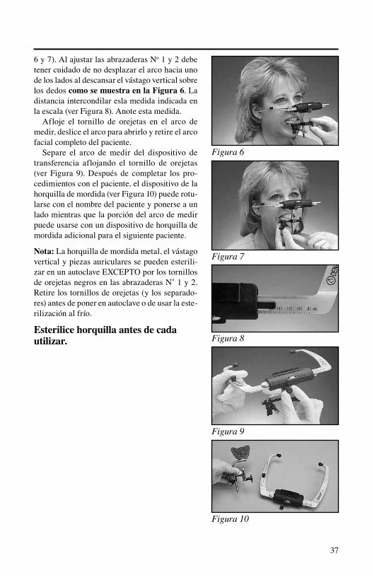
6 y 7). Al ajustar las abrazaderas No 1 y 2 debe tener cuidado de no desplazar el arco hacia uno de los lados al descansar el vástago vertical sobre los dedos como se muestra en la Figura 6. La distancia intercondilar esla medida indicada en la escala (ver Figura 8). Anote esta medida.
Afloje el tornillo de orejetas en el arco de medir, deslice el arco para abrirlo y retire el arco facial completo del paciente.
Separe el arco de medir del dispositivo de transferencia aflojando el tornillo de orejetas (ver Figura 9). Después de completar los pro-cedimientos con el paciente, el dispositivo de la horquilla de mordida (ver Figura 10) puede rotu-larse con el nombre del paciente y ponerse a un lado mientras que la porción del arco de medir puede usarse con un dispositivo de horquilla de mordida adicional para el siguiente paciente.
Nota: La horquilla de mordida metal, el vástago vertical y piezas auriculares se pueden esterili-zarenunautoclaveEXCEPTOporlostornillosdeorejetasnegrosenlasabrazaderasN˚1y2.Retire los tornillos de orejetas (y los separado-res) antes de poner en autoclave o de usar la este-rilización al frío.
Esterilice horquilla antes de cada utilizar.
Figura 6
Figura 7
Figura 8
Figura 9
Figura 10

38
Un beneficio de usar el arco facial Slidematic de Denar®esquesepuedenusarmúltiplesdis-positivos de transferencia con sólo un arco de medir.Enalgunoscasos,elmontajedelmoldemaxilar puede delegarse al laboratorio sin perder la precisión ni enfrentarse con un intervalo sin capacidad para transferencia con arco facial en elconsultorioodontológico.Ellaboratoriopuedeconectar un índice articulador a su propio articu-lador Denar® y montar el molde maxilar usando solamente el dispositivo de horquilla de mordida proveniente del consultorio odontológico. Cada índice del articulador coloca el dispositivo de la horquilla de mordida en cualquier articulador Denar®, de modo que la relación con los cóndilos registrada en el paciente se pueda reproducir con precisión en el articulador.
Índice del articulador DenarReemplace el cuadro incisal sobre el articu-
lador con el índice del articulador (ver la Figu-ra11).Conlosnúmerosdeabrazadera1y2enposición vertical, asegure el vástago vertical de la horquilla de mordida en el orificio del índice del articulador. Apriete el tornillo de orejetas en elbordefrontaldelíndice(verlaFigura12).Elpuntero incisal deberá fijarse en la parte superior del inserto deslizable sobre el índice del articula-dor (ver la Figura 13).
Índice del articulador HanauRetire la placa de montaje del miembro infe-
rior. Usando el tornillo de mariposa del miembro inferior, sujete el índice Hanau con el orificio del conjunto de transferencia en la parte frontal del articulador.Conlosnúmerosdeabrazadera1y2 en posición vertical, asegure el vástago verti-cal de la horquilla de mordida en el orificio del índice Hanau. Apriete el tornillo de orejetas en el borde frontal del índice (ver la Figura 14).
Índice tipo tornillo Whip MixRetire la placa de montaje del miembro infe-
rior. Usando el tornillo de mariposa del miembro inferior, sujete el índice tipo tornillo Whip Mix con el orificio del conjunto de transferencia en lapartefrontaldelarticulador.Conlosnúmerosde abrazadera 1 y 2 en posición vertical, asegu-re el vástago vertical de la horquilla de mordida
IV. Procedimiento de montaje
Figura 11
Figura 12
Figura 14
Figura 15
Figura 13
39
Figura 16
Figura 17
Figura 18
Figura 19
en el orificio del índice tipo tornillo Whip Mix. Apriete el tornillo de orejetas en el borde frontal del índice (ver la Figura 15).
Índice de montaje rápido Whip MixRetire la placa de montaje del miembro infe-
rior. Coloque el índice de montaje rápido Whip Mix sobre la base de montaje magnética con el orificio del conjunto de transferencia en la par-te frontaldel articulador.Con losnúmerosdeabrazadera 1 y 2 en posición vertical, asegure el vástago vertical de la horquilla de mordida en el orificio del índice de montaje rápido Quick Mount. Apriete el tornillo de orejetas en el borde frontal del índice (ver la Figura 16).
Montaje del molde maxilarSujete una placa de montaje al miembro
superior. Cerciórese de que el puntero incisal se encuentre en la posición de cero y que el miem-bro superior esté nivelado y paralelo a la parte superior del cuadro.
Coloque el molde maxilar en el índice del registro de mordida sobre la horquilla de mordi-da y cierre el articulador para comprobar si hay un espacio adecuado entre la base del molde y la placa de montaje. Monte el molde con yeso en la placa de montaje (ver la Figura 17). A pesar de que no es necesario, algunos profesionales prefieren usar un soporte de molde maxilar para evitar la torsión durante el procedimiento de montaje. Una vez que el yeso se haya fijado, qui-te la transferencia y vuelva a colocar el cuadro incisal en el articulador.
Montaje del molde mandibularSujete una placa de montaje al miembro infe-
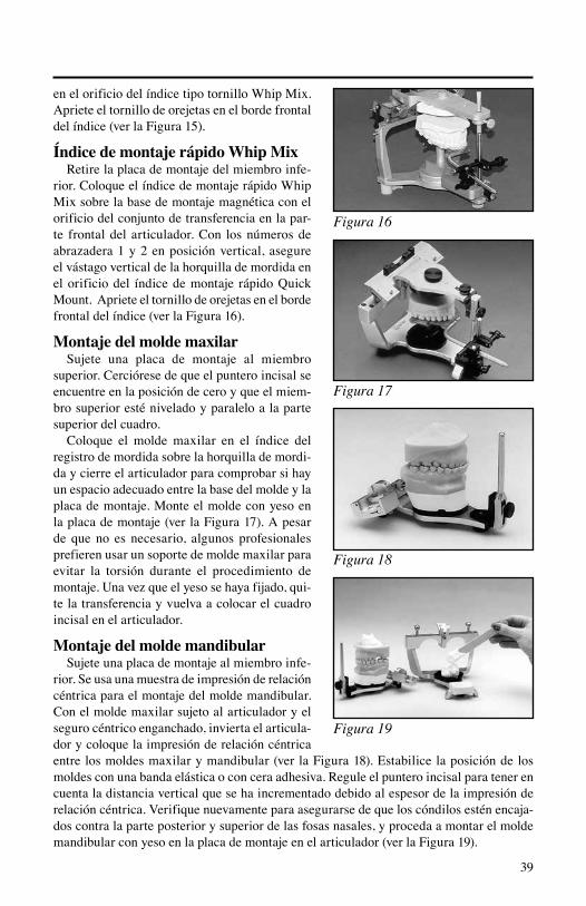
rior. Se usa una muestra de impresión de relación céntrica para el montaje del molde mandibular. Con el molde maxilar sujeto al articulador y el seguro céntrico enganchado, invierta el articula-dor y coloque la impresión de relación céntrica entrelosmoldesmaxilarymandibular(verlaFigura18).Estabilicelaposicióndelosmoldes con una banda elástica o con cera adhesiva. Regule el puntero incisal para tener en cuenta la distancia vertical que se ha incrementado debido al espesor de la impresión de relación céntrica. Verifique nuevamente para asegurarse de que los cóndilos estén encaja-dos contra la parte posterior y superior de las fosas nasales, y proceda a montar el molde mandibular con yeso en la placa de montaje en el articulador (ver la Figura 19).

40
ElSlidematicutilizayaseaunahorquillademordidadéntulaounaedéntula.Elarcofacial Slidematic puede usarse con otros articuladores e índices disponibles para el Hanau™ y Whip Mix®.
V. Accessorios Slidematic
Horquillas de mordida normalesPiezaN˚200029 Déntulo 200030 Edéntulo
Índices de articuladorPiezaN˚200080 Denar® 200082 Hanau™ 200088 Whip Mix®
200088Q Whip Mix® QuickMount
OtrosPiezaN˚200009-1Dispositivode transferencia 200007 Juego de horquilla de mordida/vástago 101217 Soporte de molde maxilar
VI. Pedidos
Whip Mix Corporation garantiza por un período de un año, que el arco facial Slidematic está libre de defec-tos de materiales o mano de obra. Encaso de haber un defecto, sírvase noti-ficar por escrito a la fábrica acerca del defecto antes de devolver el instrumento. Whip Mix Corporation, a su discreción, reparará, reemplazará o emitirá un crédito por tales defectos.
Debido a que Whip Mix Corporation está continuamente avanzando en el dise-ño de sus productos y métodos de manu-factura, se reserva el derecho de mejorar, modificar o suspender la producción de sus productos en cualquier momento, o de cambiar las especificaciones o precios sin previo aviso y sin incurrir en obligaciones.
VII. Garantía
Horquillas de mordida normales Índices
Denar® y Whip Mix® son marcas comerciales registradas y Hanau™ es una marca comercial de Whip Mix Corporation.


Whip Mix Corporation 361 Farmington Avenue Louisville, KY 40209 Toll-Free: 1-800-626-5651 Fax: 1-502-634-4512 www.whipmix.com
EURepresentative WhipMixEuropeGmbH Raudestraße 2 D-44141 Dortmund Germany Phone: 49 231 567 70 8-0 Fax: 49 231 567 70 8-50 For International Customers: U.S. Phone: 1-970-472-1635
Denar® and logo are registered trademarks of Whip Mix Corporation
© 2012 Whip Mix Corporation
U.S. Patent Nos. 4,836,779; 5,009,594
PN 8053-8 FN 80538-F AG R0612


![Implants and all-ceramic restorations in a patient treated ...s-space.snu.ac.kr/bitstream/10371/72141/1/jap-2-97[1].pdf · Facebow transfer and mounting on the casts on the ... aggressive](https://static.fdocuments.us/doc/165x107/5eb52f7c01a9ec43141cb8bb/implants-and-all-ceramic-restorations-in-a-patient-treated-s-spacesnuackrbitstream10371721411jap-2-971pdf.jpg)


![Untitled-2 [whipmix.com]whipmix.com/wp-content/uploads/Max-LCD.pdf · Title: Untitled-2 Author: User Created Date: 20190226164105Z](https://static.fdocuments.us/doc/165x107/5f48bdba65c61b621155ddd7/untitled-2-title-untitled-2-author-user-created-date-20190226164105z.jpg)
