Slide Retainerselpasomoldsupply.com/Ready/CATALOGO 2013 - Date Stamps... · 2013-04-24 · Slide...
14
Slide Retainers • A compact method of slide retention that eliminates the use of springs or costly hydraulic systems. • Interference with machine tie bars or safety gates is eliminated because the slide retainer can be installed behind or below the slide. • They can be used in multiples for larger or heavier slides. SRP-22 1-1/2 3/4 .63 .89 .61 .360 .19 1/4 X 1-1/4 22 Pounds .73 1.01 1.00 10-24 X 1/2 1/4 X 5/8 .31 SRP-44 2-1/8 1-1/4 .79 1.31 .81 .500 .25 5/16 X 1-1/2 44 Pounds .93 1.43 1.50 1/4-20 X 1/2 5/16 X 3/4 .37 SRP-88 3-3/8 1-3/4 1.18 2.08 1.30 .800 .38 3/8 X 2-1/4 88 Pounds 1.42 2.20 2.20 5/16-18 X 5/8 3/8 X 1" .50 A B C D E F R G H J S Dowel Pin Maximum Slide Weight Tapped Hole K Shoulder Screw Catalog Number Slide Retainers
Transcript of Slide Retainerselpasomoldsupply.com/Ready/CATALOGO 2013 - Date Stamps... · 2013-04-24 · Slide...

Slide Retainers
• A compact method of slide retention that eliminates the use of springs or costly hydraulic systems.
• Interference with machine tie bars or safety gates is eliminated because the slide retainer can be installed behind or below the slide.
• They can be used in multiples for larger or heavier slides.
SRP-22 1-1/2 3/4 .63 .89 .61 .360 .19 1/4 X 1-1/4 22 Pounds .73 1.01 1.00 10-24 X 1/2 1/4 X 5/8 .31SRP-44 2-1/8 1-1/4 .79 1.31 .81 .500 .25 5/16 X 1-1/2 44 Pounds .93 1.43 1.50 1/4-20 X 1/2 5/16 X 3/4 .37SRP-88 3-3/8 1-3/4 1.18 2.08 1.30 .800 .38 3/8 X 2-1/4 88 Pounds 1.42 2.20 2.20 5/16-18 X 5/8 3/8 X 1" .50
A B C D E F R G H J SDowelPin
MaximumSlide
Weight
Tapped Hole
K
ShoulderScrew
CatalogNumber
Slide Retainers

Slide LatchHIGH HARDNESS
BODY
.075 OFF CENTER
.498
.295
.150
.050
.145
.075 OFF CENTER
TAPPED 4-40 THRUC’BORE FOR 2-56
.150
LOCK
SLK-8-HHRated to carry a weight up to 8 pounds. 100% interchangeable with SLK-8A
INSTALLATION – LOCK
INSTALLATION – BODY
DESIGNGUIDELINES
FULL STROKE MINUS -.020
NOTE: Set angle pin to release .020 from full stroke. Striker will snap to full stroke to assure re-entry clearance of angle pin
SLK-25-HHRated to carry a weight up to 25 pounds. 100% interchangeable with SLK-25A
FULL STROKE MINUS -.030
NOTE: Set angle pin to release .030 from full stroke. Striker will snap to full stroke to assure re-entry clearance of angle pin
FULL STROKE MINUS -.030
NOTE: Set angle pin to release .030 from full stroke. Striker will snap to full stroke to assure re-entry clearance of angle pin
DESIGNGUIDELINES
R .083
INSTALLATION – LOCK
INSTALLATION – BODY
SKD 11 HRC 56-58
SKD 11 HRC 56-58
Slide Latch

MACHINING DATA
Slide-Latch model SLK-50HH is rated to carry a weight of up to 50 pounds. Ideal for die cast mold slide applications. Multiple Slide-Latches can be easily machined and mounted in mold slides for higher load retentions.
SLK-50HH
SKD 11 HRC 56-58
Slide LatchSlide Latch

Spacer PlatesSpacer Plates
• DMS round tapered interlocks provide positive alignment ofcavities and cores.
• Extra grind stock is provided at the back of both male andfemale for positive fitting.
1/2 11/16 3/16 10-24 SP0503/4 1" 3/16 1/4-20 SP0751" 1-3/16 3/16 1/4-20 SP100
1-1/2 1-11/16 1/4 5/16-18 SP1502" 2-3/16 1/4 5/16-18 SP200
O.D. D T ScrewSize
CatalogNumber
O.D.+.0000-.0005
MALE
I.D. L TAPSIZE
M+.010+.015
CatalogNumber
11/16 MTL050-117/8 MTL050-14
1/2 5/16 1/4 10-241-3/16 MTL050-19
1-3/8 MTL050-2211/16 MTL075-11
7/8 MTL075-143/4 1/2 9/32 1/4-20
1-3/16 MTL075-191-3/8 MTL075-2211/16 MTL100-11
7/8 MTL100-141" 5/8 11/32 1/4-20
1-3/16 MTL100-191-3/8 MTL100-221-1/8 MTL150-18
1-1/2 1" 1/2 5/16-18 1-3/8 MTL150-221-5/8 MTL150-261-1/8 MTL200-18
2" 1-1/2 1/2 5/16-18 1-3/8 MTL200-221-5/8 MTL200-26
O.D.+.0000-.0005
FEMALE
I.D.TAPSIZE
M+.010+.015
CatalogNumber
11/16 FTL050-117/8 FTL050-14
1/2 5/16 10-241-3/16 FTL050-19
1-3/8 FTL050-2211/16 FTL075-11
7/8 FTL075-143/4 1/2 1/4-20
1-3/16 FTL075-191-3/8 FTL075-2211/16 FTL100-11
7/8 FTL100-141" 5/8 1/4-20
1-3/16 FTL100-191-3/8 FTL100-221-1/8 FTL150-18
1-1/2 1" 5/16-18 1-3/8 FTL150-221-5/8 FTL150-261-1/8 FTL200-18
2" 1-1/2 5/16-18 1-3/8 FTL200-221-5/8 FTL200-26
Tapered Interlocks

Side Locks
Male half: O-6 steel (58-60 Rc)Black Oxide Finish
Female half: S-7 steel (54-56 Rc)Titanium Nitrided (80 Rc)
• Supplied with socket head cap screws.• Sold in sets only.
PLS-100 1.000 .870 1.125 .375 1.310 .440 .250 3/16 10-32 X 1/2PLS-125 1.250 .870 .875 .437 1.230 .500 .250 1/4 10-32 X 1/2PLS-150 1.500 .870 1.000 .500 1.250 .625 .281 1/4 10-32 X 5/8PLS-200 2.000 .870 1.375 .620 1.375 .680 .375 1/4 1/4-20 X 3/4PLS-300 3.000 1.120 1.875 .745 2.000 1.125 .440 5/16 1/4-20 X 7/8PLS-400 4.000 1.370 1.875 .875 2.312 1.375 .625 3/8 3/8-16 X 1PLS-500 5.000 1.370 2.375 1.120 2.625 1.750 .625 3/8 3/8-16 X 1-1/4
CatalogNumber
ESHCS
A+.0000-.0004
B+.000-.002
C+.000-.002
D+.000-.002
RF.0001/.0002Clearanceper side
G+.010-.010
Side Locks

Top Locks
Male half: O-6 steel (58-60 Rc)Black Oxide Finish
Female half: S-7 steel (54-56 Rc)Titanium Nitrided (80 Rc)
• Supplied with socket head cap screws.• Sold in sets only.
Catalog A D C B E F G1 G2 R SHCS Number +.0000 +.000 +.000 +.000 +.010 .0001/.0003 +.010 +.010 -.0004 -.002 -.002 -.002 -.010 Clearance per side -.010 -.010 MALE FEMALE TL62X125 1.250 .625 .625 .500 .410 .438 .312 .875 1/4 #6-32 X 5/8 #6-32 X 3/4 TOPL125 1.250 .750 .625 .500 .380 .438 .375 .875 1/4 #8-32 X 5/8 #8-32 X 3/4 TL100X150 1.500 1.000 .875 .375 .500 .500 .500 1.00 1/4 #10-32 X 1/2 #10-32 X 1 TOPL200 2.000 1.125 .875 .625 .500 .750 .563 1.375 3/8 1/4-20 X 3/4 1/4-20 X 1 TL150X250 2.500 1.500 1.375 .625 .750 1.000 .750 1.750 3/8 1/4-20 X 3/4 1/4-20 X 1-1/2 TOPL300 3.000 1.750 1.250 .875 .750 1.125 .875 2.250 1/2 5/16-18 X 1 5/16-18 X 1-1/4 TL200X350 3.500 2.000 1.750 .750 1.00 1.500 1.00 2.500 1/2 3/8-16 X 7/8 3/8-16 X 2
Top Locks

Guide Locks
GL-1.5 1.500 1.000 .500 .850 .375 .500 .500 .250 .187 #6-32 #10-32 X 1” #10-32 X 5/8GL-2.5 2.500 1.500 1.000 1.350 .625 .750 .750 .310 .250 1/4-20 1/4-20 X 1-1/2 1/4-20 X 7/8GL-3.5 3.500 2.000 1.500 1.730 .750 1.000 1.000 .440 .375 3/8-16 3/8-16 X 2” 3/8-16 X 1-1/4GL-4.5 4.500 2.500 2.000 2.100 .875 1.250 1.250 .560 .500 3/8-16 1/2-13 X 2-1/4 1/2-13 X 1-1/2
CatalogNumber
C+.0000-.0003
F+.000-.005
SHCS
MALE (2) FEMALE (4)
W+.000-.010
L+.000-.010
T+.0000-.0003
H+.000-.010
M XJack
Screw
S+.010-.010
R
Because Guide Lockscan be used inside themold as well as at theparting line, DMS hasadded a jack screw holeto the male interlock.This allows removalwithout damage to themold. Also added is a 5° angle on each end of the male.
Male:AISI D2 (58-60 Rc)Titanium Nitride Coated78-80 Rc
Female:AISI 1045 (60-62 Rc)Black Oxide Finish
Guide Locks

Material: YK30 56-60 Hrc
• Supplied with sockethead cap screws.
• Sold in sets only.
OSL16x20 40 16 20 22 20 11 6.6 11 6.8 26 15 7 6OSL16x40 40 16 40 22 20 11 6.6 11 6.8 26 15 7 6OSL20x25 45 20 25 27 22 13 6.6 11 6.8 31 19 7 6OSL20x50 45 20 50 27 22 13 6.6 11 6.8 31 19 7 6OSL25x32 50 25 32 36 25 14 6.6 11 6.8 35 27 9 8OSL25x63 50 25 63 36 25 14 6.6 11 6.8 35 27 9 8OSL32x40 63 32 40 46 32 19 9 15 9 45 35 11 8OSL32x80 63 32 80 46 32 19 9 15 9 45 35 11 8OSL40x50 85 40 50 56 36 22 11 18 11 60 40 15 10OSL40x100 85 40 100 56 36 22 11 18 11 60 40 15 10OSL50x56 100 50 56 66 40 24 14 20 13 74 48 18 10OSL50x112 100 50 112 66 40 24 14 20 13 74 48 18 10
Note: All dimensions & tolerances are in millimeters
CatalogNumber t3 d1b1 b2 l1 l2 t1 b3 l3 l4 rd2 t2
E Side Locks(Graphite Impregnated)(Graphite Impregnated)
SquareInterlocks
Square Interlocks
SIL-20 20 20 28 M5 M4 12 4 4SIL-25 25 25 32 M6 M5 13 8 5SIL-32 32 32 36 M8 M6 15 12 6SIL-40 40 40 45 M10 M8 17 10 6
Note: All dimensions & tolerances are in millimeters
CatalogNumber H1 H2A B L d1 d2 RMaterial: YK30 56-60 Hrc
• Easily installed and removed from theparting line.
• Supplied with socket head cap screws.• Sold in sets only.
E Side Locks

CUMSAwww.cumsa.com

Date Stamps
Inserts
CAD files and flash demo at:CUMSAwww.cumsa.com
• Material is INOX. 1.4034 48-54HRC• Insert changes can be done while the tool
is still in the press.• To replace inserts, simply turn clockwise
until the unit clicks (about 8 revolutions) mating the insert flush with the outer ring.
*Assemblies supplied complete with outer ring and arrow insert.(1) When ordering, add the year required to the part number (FA.04221211)(2) The number of years that fit on the ‘Year’ outer ring.
• Material is INOX. 1.4034 48-54HRC.• Maximum working temperature is 150°C
(1) When ordering, add the year required to the part number (IA.227511)
12Months 12Months +Year Years Blank
12 Months 12 Mon. + Yr.1 Years1 Blank 31 Days Shifts A C D E L N2
FA.0422SF FA.042212- _ _ FA.042204- _ _ FA.042200 FA.0422SP 4 2.2 6 3.5 12 4 FA.0530SF FA.053012- _ _ FA.053004- _ _ FA.053000 FA.0530SP 5 3 6 3.5 12 4 FA.0632SF FA.063212- _ _ FA.063205- _ _ FA.063200 FA.0632-31 FA.0632SP 6 3.2 12 4 20 5 FA.0847SF FA.084712- _ _ FA.084705- _ _ FA.084700 FA.0847-31 FA.0847SP 8 4.7 12 6 20 5 FA.1057SF FA.105712- _ _ FA.105706- _ _ FA.105700 FA.1057-31 FA.1057SP 10 5.7 12 8 20 6 FA.1267SF FA.126712- _ _ FA.126708- _ _ FA.126700 FA.1267-31 FA.1267SP 12 6.7 12 10 20 8 FA.1687SF FA.168712- _ _ FA.168710- _ _ FA.168700 FA.1687-31 FA.1687SP 16 8.7 12 12 20 10 FA.2007SF FA.200712- _ _ FA.200710- _ _ FA.200700 FA.2007-31 FA.2007SP 20 10.7 12 14 20 10
Arrow Arrow & C M
only Year1
IA.2275SF IA.2275 _ _ 2.2 7.7 IA.3075SF IA.3075 _ _ 3 7.7 IA.3217SF IA.3217 _ _ 3.2 17 IA.4717SF IA.4717 _ _ 4.7 17 IA.5717SF IA.5717 _ _ 5.7 17 IA.6717SF IA.6717 _ _ 6.7 17 IA.8717SF IA.8717 _ _ 8.7 17 IA.1007SF IA.1007 _ _ 10.7 17
Date Stamps

12Months+Year Blank A B C E N FD.080512__ FD.080500 8 5.5 3 6 5 FD.120812__ FD.120800 12 8 4 10 6 FD.161012__ FD.161000 16 10.5 5.3 12 10
•Replacestheneedfor2separatedatestamps•Noneedtomachine2separateholes•Minimumspacerequiredforinstallation•Specialengravingavailableuponrequest.•Material:INOX.1.4034
Hardened51±3HRC•Maximumworkingtemperature100°C•ThisisaCUMSApatentedsystem
IMPORTANT:Tochangethemonth,turncounterclockwise(thetwoinnerringsmove,Fig.1).Tochangetheyear,turnclockwise(onlythecentralringmoves,Fig.2).
Toorder—Addthelasttwodigitsofthestartorbaseyeartocatalognumber.Exampleforstartorbaseyearof2011:FD-08051211
Fig.1 Fig.2 Tochangemonth Tochangeyear
CADfilesandflashdemoat:CUMSAwww.cumsa.com
Double Date
Date Stamps Date Stamps Double Date
StampDouble Date
Stamp
12Months12Months
Years2 A B C D No.of
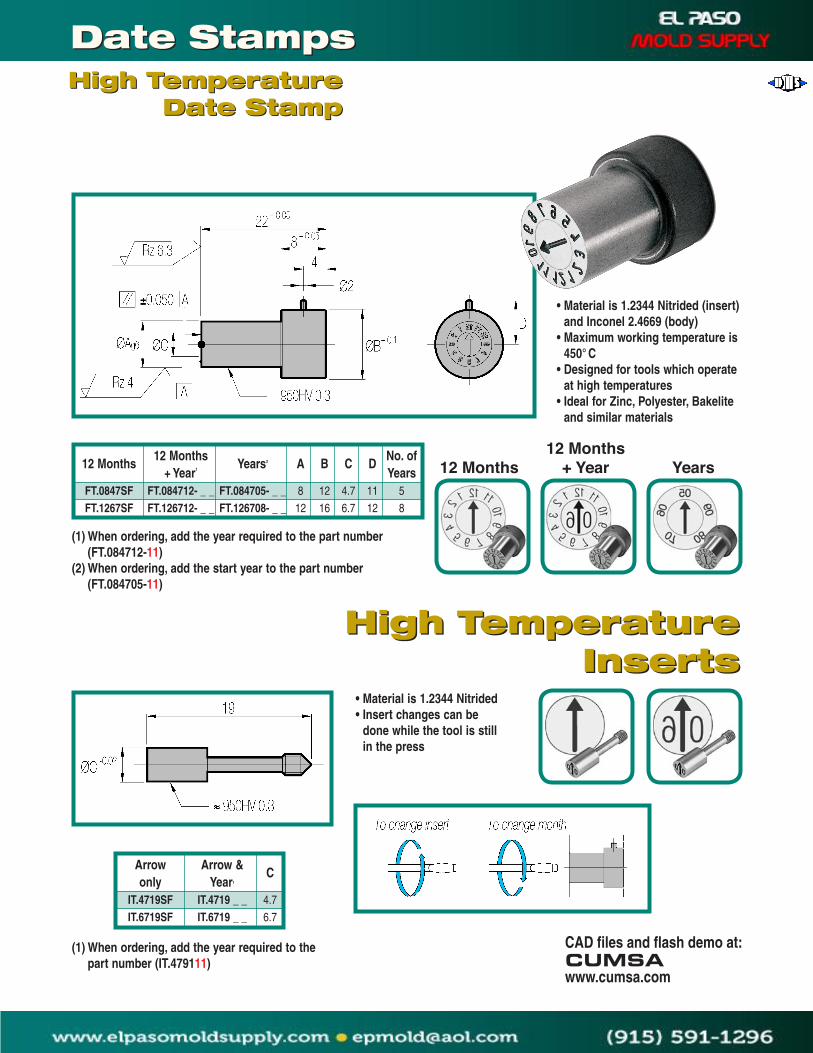
+Year1 Years FT.0847SF FT.084712-__ FT.084705-__ 8 12 4.7 11 5 FT.1267SF FT.126712-__ FT.126708-__ 12 16 6.7 12 8
High TemperatureInserts
High TemperatureInserts
(1)Whenordering,addtheyearrequiredtothepartnumber(FT.084712-11)
(2)Whenordering,addthestartyeartothepartnumber(FT.084705-11)
•Materialis1.2344Nitrided(insert)andInconel2.4669(body)
•Maximumworkingtemperatureis450°C
•Designedfortoolswhichoperateathightemperatures
•IdealforZinc,Polyester,Bakeliteandsimilarmaterials
•Materialis1.2344Nitrided•Insertchangescanbe
donewhilethetoolisstillinthepress
12Months 12Months +Year Years
(1)Whenordering,addtheyearrequiredtothepartnumber(IT.479111)
Arrow Arrow&C
only Year1
IT.4719SF IT.4719__ 4.7 IT.6719SF IT.6719__ 6.7
CADfilesandflashdemoat:CUMSAwww.cumsa.com
High TemperatureDate Stamp
High TemperatureDate Stamp
Date Stamps Date Stamps

CAD files and flash demo at:CUMSAwww.cumsa.com
• Material is INOX. 1.4034 48-54HRC.• This is a CUMSA patented system.
Block Base3 & 4 ZoneBlock Base3 & 4 Zone
The Block Base is the most versatile engraving unit on the market.With 3 and 4 zone configurations you can view any sort of standardizedinformation about your part.
BM.160603 16 6.5 8 3BM.180604 18 6.5 8 4BM.220903 22 8.7 10 3BM.250904 25 8.7 10 4BM.281103 28 11.5 12 3BM.321104 32 11.5 12 4
CatalogNumber A C E Number
of Zones
6,5 PM0615-098,7 PM0915-09
11,5 PM1115-09
Catalog NumberC6,5 PM0615-1018,7 PM0915-101
11,5 PM1115-101
Catalog NumberC6,5 PM0615-1028,7 PM0915-102
11,5 PM1115-102
Catalog NumberC
6,5 PM0615-1038,7 PM0915-103
11,5 PM1115-103
Catalog NumberC6,5 PM0615-104-__ __8,7 PM0915-104-__ __11,5 PM1115-104-__ __
1Catalog NumberC6,5 PM0615-105-__ __8,7 PM0915-105-__ __11,5 PM1115-105-__ __
1Catalog NumberC
6,5 PM0615-1068,7 PM0915-106
11,5 PM1115-106
Catalog NumberC6,5 PM0615-1078,7 PM0915-107
11,5 PM1115-107
Catalog NumberC
6,5 PM0615-008,7 PM0915-00
11,5 PM1115-00
Catalog NumberC6,5 PM0615-078,7 PM0915-07
11,5 PM1115-07
Catalog NumberC
Block InsertsBlock InsertsBlank
Food
Months
0-30
Recycle
Shift
Months & Year
31 Days
Years
0-50 1 Add starting year after the dash(PM0615-104-06)
Date Stamps Date Stamps

Sintered Vents
PLASTIC INJECTION MOLDING (Pore Diameter: 0.03–0.10mm)
CAT. NO. O.D. EFF. D. PORES L 003–0610 6 2.5 880 10 003–0810 8 2.5 880 10 003–1010 10 2.5 880 10 005–0610 6 3.5 880 10 005–0810 8 3.5 880 10 005–1010 10 3.5 880 10 01–0810 8 5.5 880 10 01–1010 10 5.5 880 10
LOW PRESSURE DIE-CASTING AND VACUUM CASTING(Pore Diameter: 0.3± mm)
CAT. NO. DIA. PORES L 03–0510 5 90 10 03–0610 6 90 10 03–0615 6 90 15 03–0810 8 200 10 03–0815 8 200 15 03–1010 10 340 10 03–1015 10 340 15 03–1210 12 340 10 03–1215 12 340 15 03–1415 14 550 15
GRAVITY DIE-CASTING (Pore Diameter: 0.5± mm)
CAT.NO. DIA. PORES L 05–0310 3 40 10 05–0410 4 40 10 05–0510 5 60 10 05–0610 6 60 10 05–0615 6 60 15 05–0810 8 100 10 05–0815 8 100 15 05–1010 10 200 10 05–1015 10 200 15 05–1210 12 200 10 05–1215 12 200 15 05–1415 14 340 15 05–1615 16 240 15 05–1815 18 550 15 05–2015 20 550 15 05–2815 28 970 15
CODING SYSTEM EXAMPLE: 005–0610 0.05 Pore Dia. (mm) 06 Vent Dia. (mm) 10 Vent L. (mm)
PRODUCTIVITY: Fast and easy exchange of venting plugs; easy cleaning of molding dies.EFFICIENCY: Perforation volumes are 5–30 times higher than ordinary venting plugs.DURABILITY: Decrease replacement frequency of venting plugs.QUALITY: Drastically decreases defects such as pin holes, mis-run, and short-shots.SELECTION: Pore sizes range from 0.03 to 0.5mm; length and diameter of vents to meet your needs.
PLEASE NOTE• We can supply custom vents made
to your specification.• During installation, do not strike the
vent pores.• Keep insertion tolerances between
0.025 and 0.05mm.• Actual pore diameters and
specifications may vary slightly and are subject to change without notice.
KIC Sintered Vents are composed of several straight and uniform pores made through a unique process to allow air or gas that gets trapped inside the mold cavity during the injection or die casting process to escape freely. To optimize mold design and reduce the possibility of manufacturing defective parts, specify strategically placed insertion points to hold the vents.KIC Sintered Vents with ultra fine pores (diameters of 0.03mm) have been used successfully in venting systems for plastic injection mold applications. The passage of trapped air and gases can be properly released while blocking the escape of molten plastic. With KIC Sintered Vents, you get shorter shot-cycles while dramatically increasing productivity.KIC Sintered Vents with a pore diameter of 0.4mm are suitable for larger, gravity die-cast parts, while 0.5mm diameter vents are more suited for smaller parts. Low pressure die-cast, or vacuum casting parts require pore diameters between 0.2 and 0.3mm.
Sintered Vents