slide
21
By: DESMOND LAI CHENY YIN Student ID: 52931 Supervisor : MR MATTHEW TEOW
-
Upload
cheng-yin-desmond-lai -
Category
Documents
-
view
119 -
download
0
Transcript of slide
By: DESMOND LAI CHENY YIN Student ID: 52931
Supervisor : MR MATTHEW TEOW
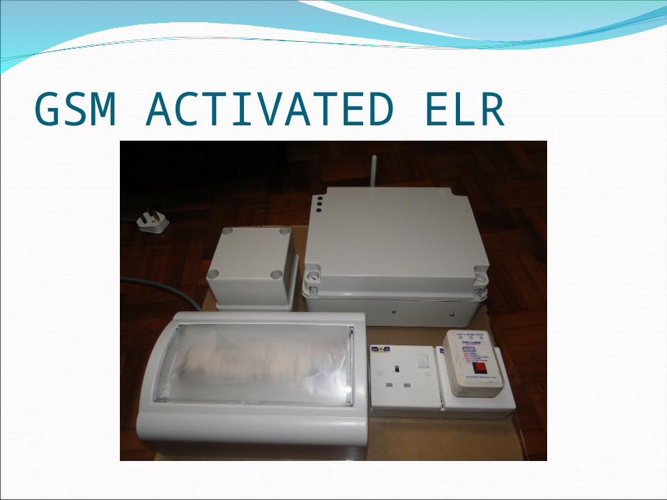
GSM ACTIVATED ELR
OBJECTIVEImplement and design the GSM activated ELR.To study the communication between GSM
modem with microcontroller.To study communication of GSM system using
AT command.To study the setting of the residual current.To protect electrical/electronic device from
burning cause by thunder.To reduce the food waste cause by power
tripped.
1. Expend project idea2. Forming flow chat3. Choosing component 4. Learn programming5. Circuit design 6. Testing breadboard 7. PCB design 8. Drilling and soldering 9. Final assemble
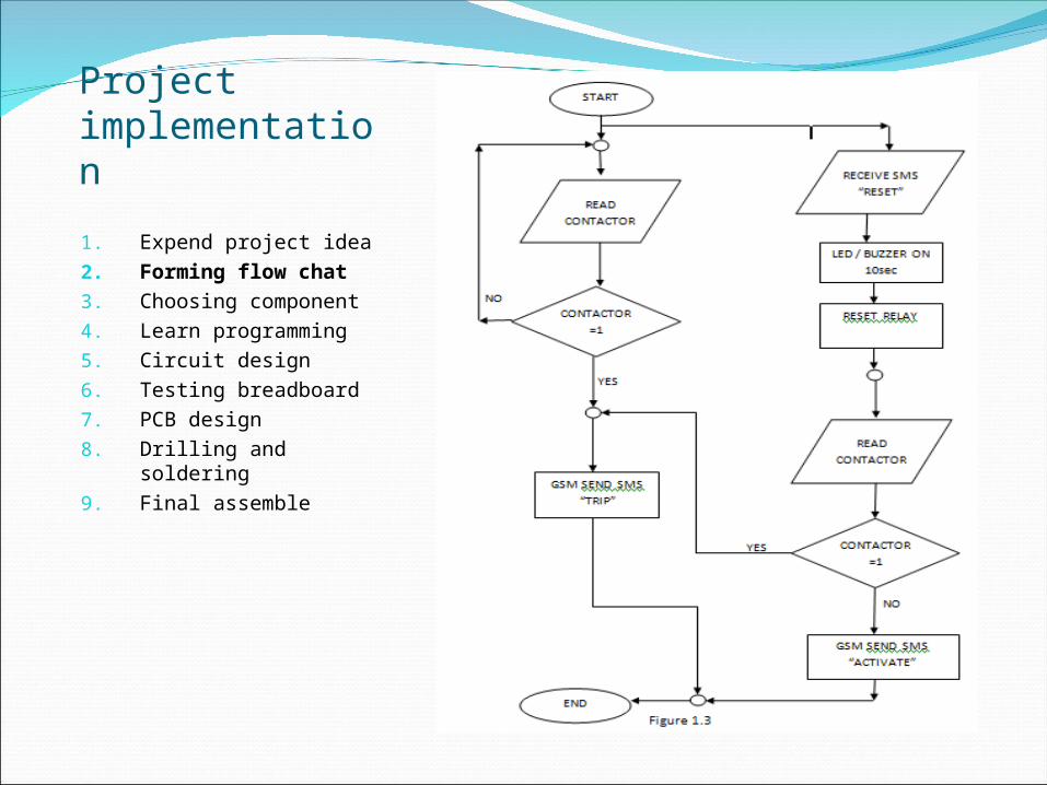
Project implementation
1. Expend project idea2. Forming flow chat3. Choosing component 4. Learn programming5. Circuit design 6. Testing breadboard 7. PCB design 8. Drilling and soldering 9. Final assemble
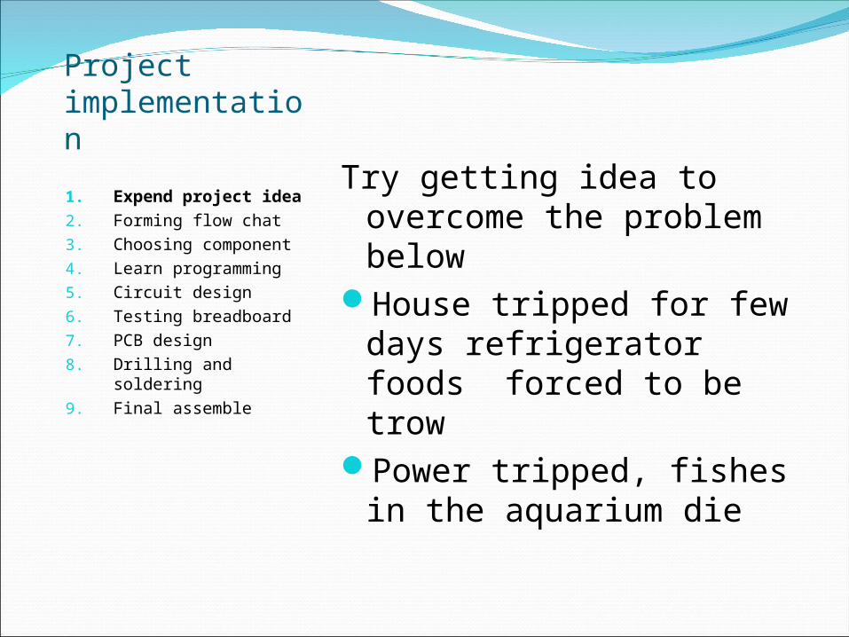
Try getting idea to overcome the problem below
House tripped for few days refrigerator foods forced to be trow
Power tripped, fishes in the aquarium die
Project implementation
1. Expend project idea2. Forming flow chat3. Choosing component 4. Learn programming5. Circuit design 6. Testing breadboard 7. PCB design 8. Drilling and soldering 9. Final assemble
Project implementation
1. Expend project idea2. Forming flow chat3. Choosing component 4. Learn programming5. Circuit design 6. Testing breadboard 7. PCB design 8. Drilling and soldering 9. Final assemble
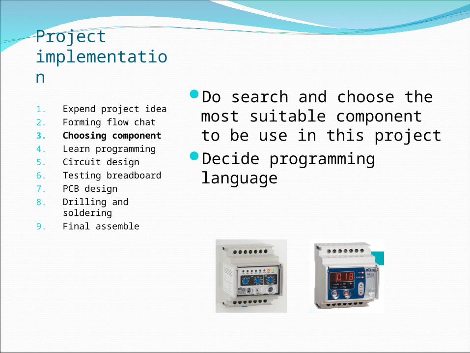
Do search and choose the most suitable component to be use in this project
Decide programming language
Project implementation
1. Expend project idea2. Forming flow chat3. Choosing component 4. Learn programming5. Circuit design 6. Testing breadboard 7. PCB design 8. Drilling and soldering 9. Final assemble
Learn basic programming using HI-TECH C language
LED blinking Uart communication AT command
Project implementation
1. Expend project idea2. Forming flow chat3. Choosing component 4. Learn programming5. Circuit design 6. Testing breadboard 7. PCB design 8. Drilling and soldering 9. Final assemble
Project implementation
1. Expend project idea2. Forming flow chat3. Choosing component 4. Learn programming5. Circuit design 6. Testing breadboard 7. PCB design 8. Drilling and soldering 9. Final assemble
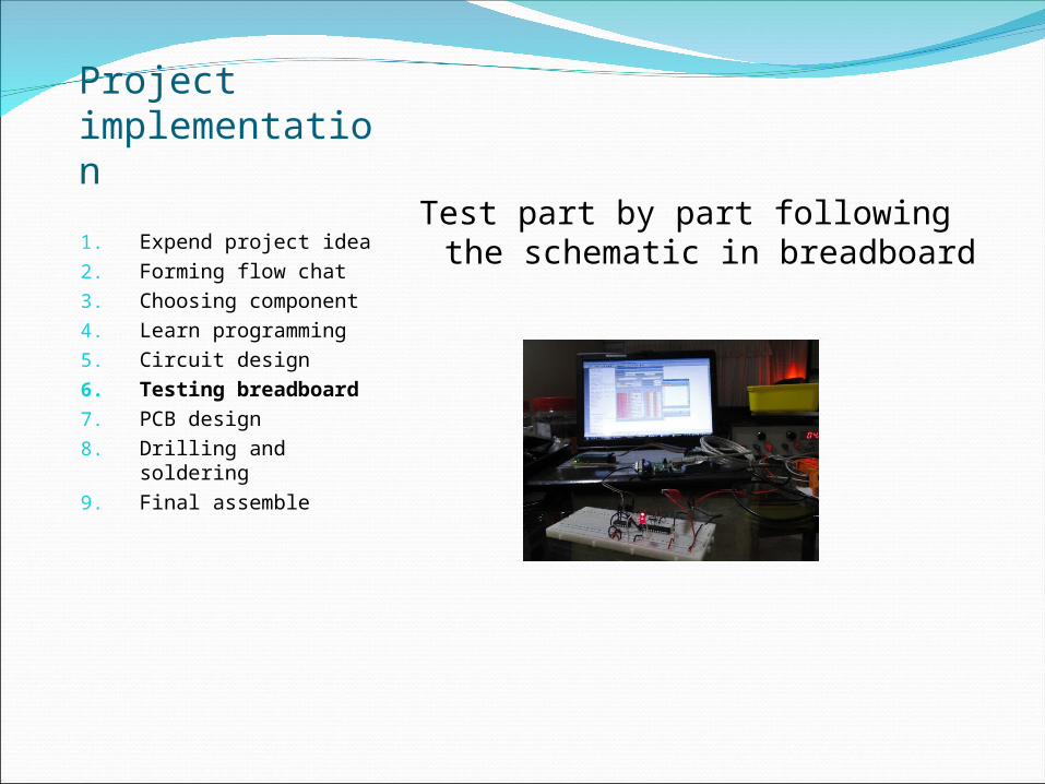
Test part by part following the schematic in breadboard
Project implementation
1. Expend project idea2. Forming flow chat3. Choosing component 4. Learn programming5. Circuit design 6. Testing breadboard 7. PCB design 8. Drilling and soldering 9. Final assemble
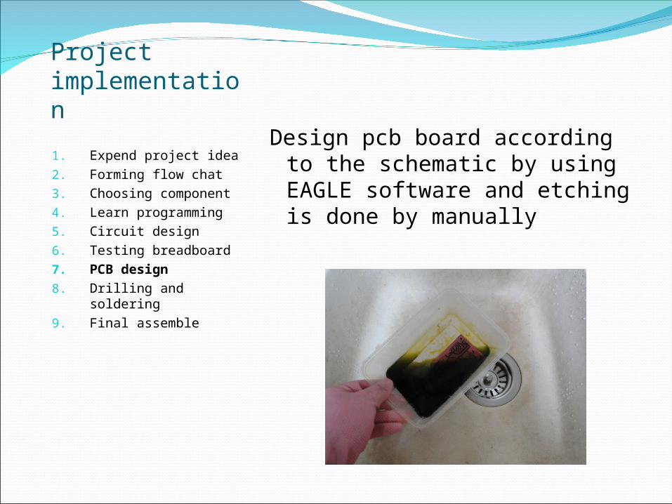
Design pcb board according to the schematic by using EAGLE software and etching is done by manually
Project implementation
1. Expend project idea2. Forming flow chat3. Choosing component 4. Learn programming5. Circuit design 6. Testing breadboard 7. PCB design 8. Drilling and
soldering 9. Final assemble
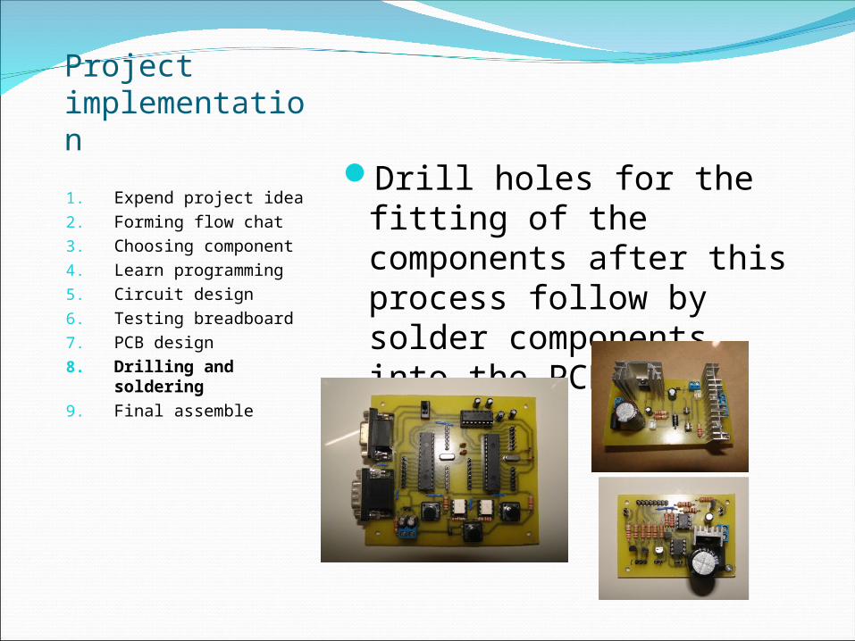
Drill holes for the fitting of the components after this process follow by solder components into the PCB board
Project implementation
1. Expend project idea2. Forming flow chat3. Choosing component 4. Learn programming5. Circuit design 6. Testing breadboard 7. PCB design 8. Drilling and soldering 9. Final assemble
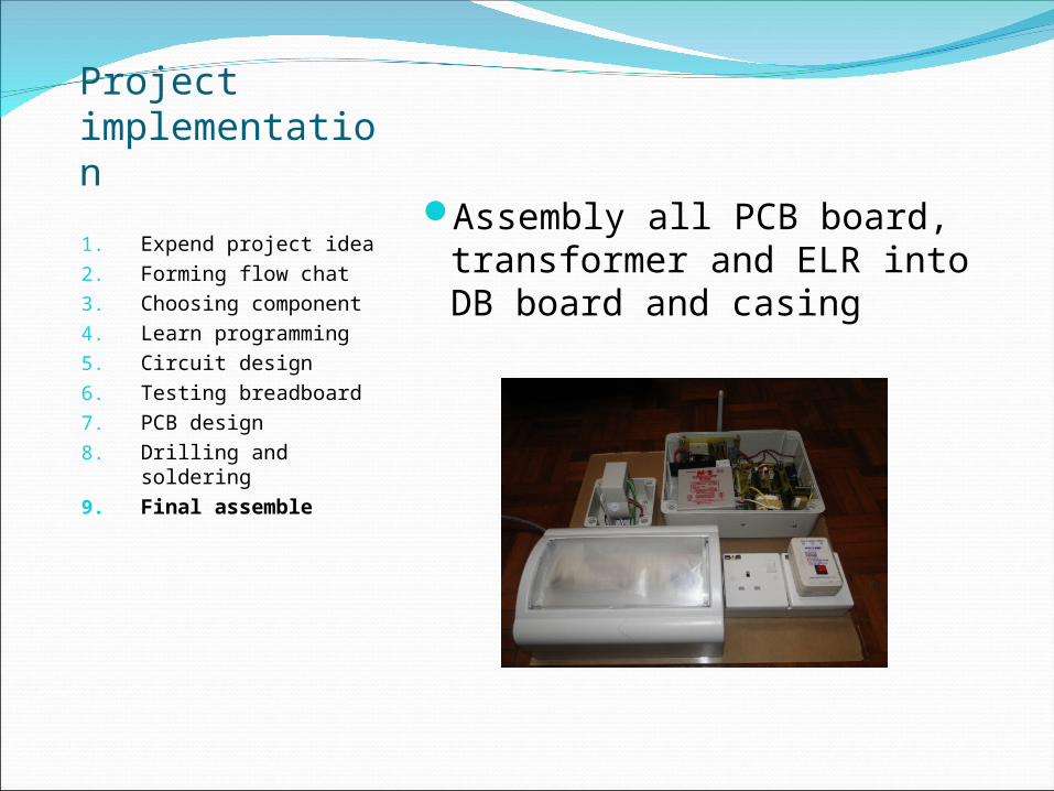
Assembly all PCB board, transformer and ELR into DB board and casing
The testing of the project was successfully done and its functioning well, the following slides shows the test result steps by steps.
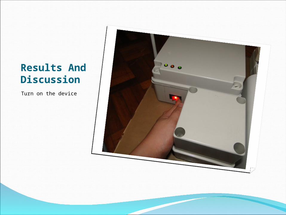
Results And DiscussionTurn on the device
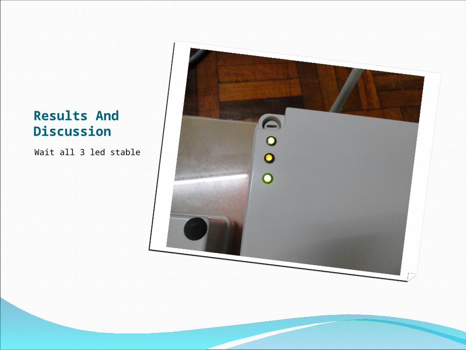
Results And DiscussionWait all 3 led stable
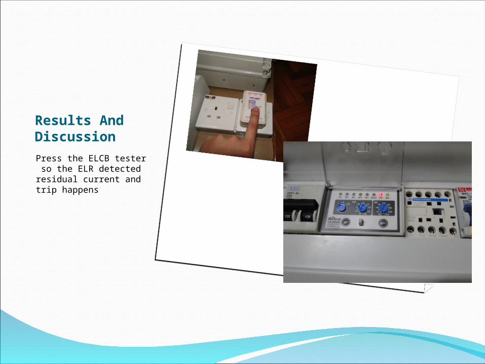
Results And DiscussionPress the ELCB tester so the ELR detected residual current and trip happens
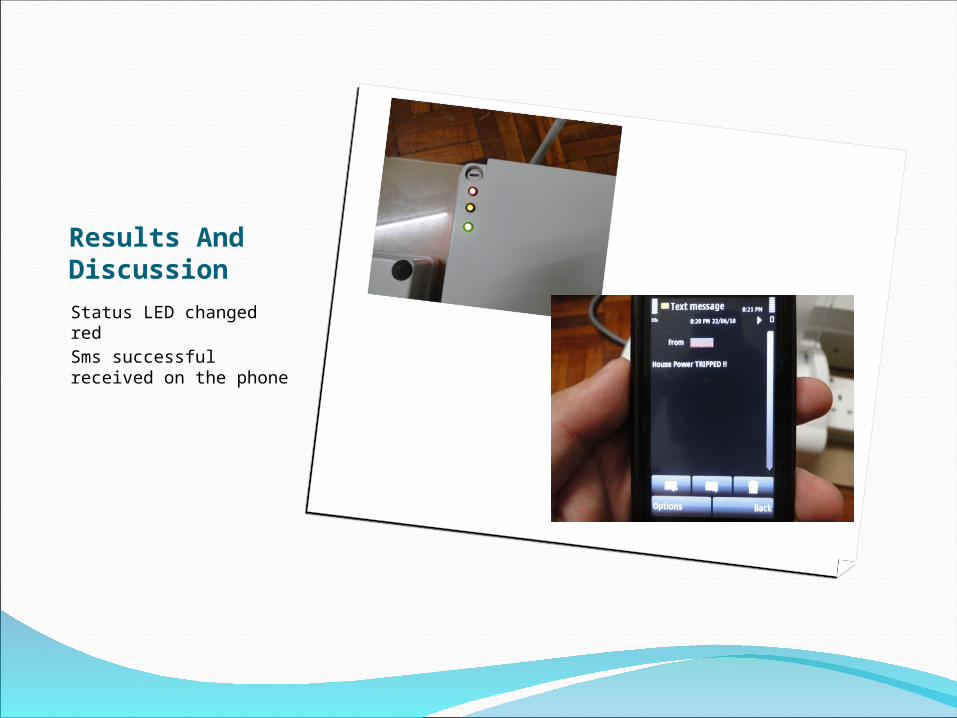
Results And DiscussionStatus LED changed red Sms successful received on the phone
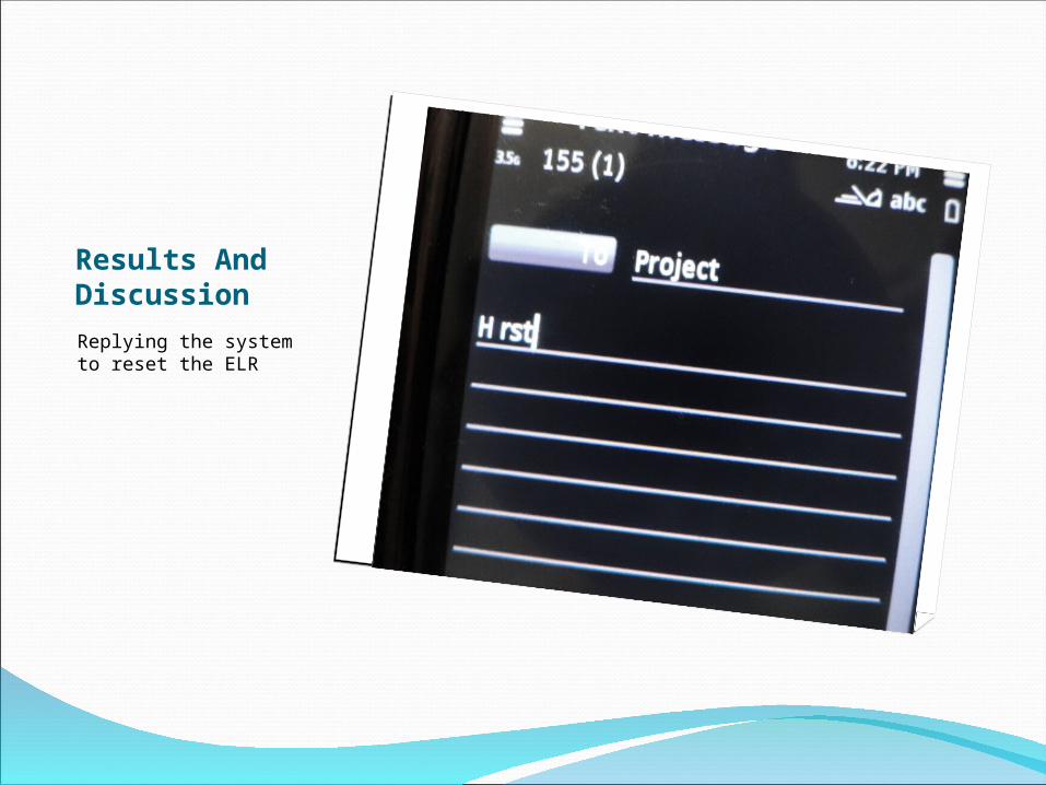
Results And DiscussionReplying the system to reset the ELR
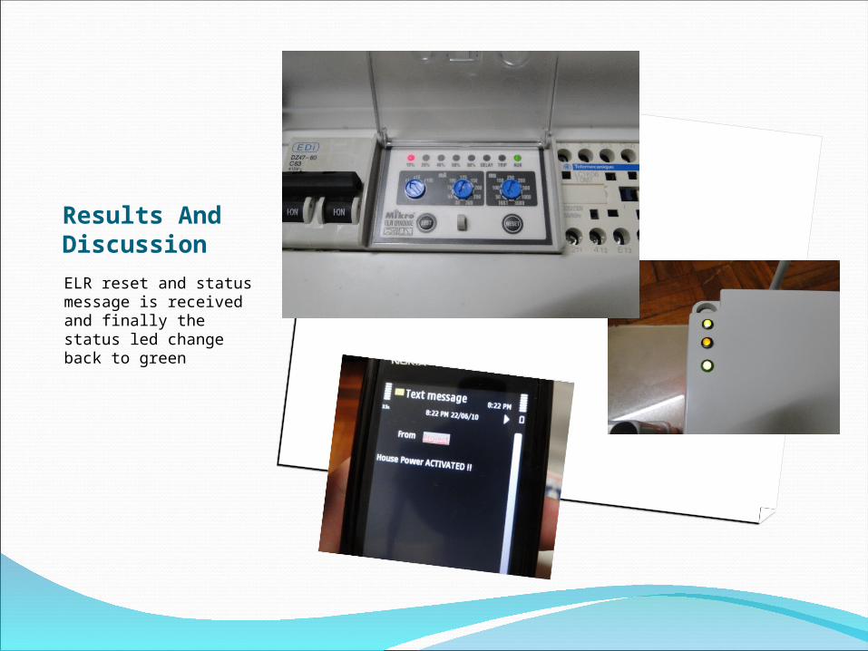
Results And DiscussionELR reset and status message is received and finally the status led change back to green
This project was focused on the implementation of GSM activated ELR was presented successfully. All objective in chapter 1 were achieve. The system is quite stable .