Slide 2 This slide shows the typical reinforcement cage...
19
Slide 1 Concrete Beams Slide 2 Typical Beam Reinforcement Tension Reinforcement Compression Reinforcement Stirrups This slide shows the typical reinforcement cage for a simple span concrete beam. The tension bars resist tension from moment which will occur in the bottom of the beam in this case; the stirrups resist shear which is highest near the supports under distributed loads (more on shear design later); and finally the compression bars (called that because they are in the compression zone of the beam) help support the top of the cage and improve the mechanical performance of the beam in some ways that we will discuss later.
Transcript of Slide 2 This slide shows the typical reinforcement cage...

Slide 1
ConcreteBeams
Slide 2 Typical Beam Reinforcement
TensionReinforcement
CompressionReinforcement
Stirrups
This slide shows the typical
reinforcement cage for a simple span
concrete beam. The tension bars resist
tension from moment which will occur
in the bottom of the beam in this case;
the stirrups resist shear which is
highest near the supports under
distributed loads (more on shear design
later); and finally the compression bars
(called that because they are in the
compression zone of the beam) help
support the top of the cage and
improve the mechanical performance
of the beam in some ways that we will
discuss later.

Slide 3
Floor Framing Plans
Slide 4
One-Way Slab
InteriorSupportBeam
ExteriorSupportBeam
One-Way Slab with Support Beams
This is the type of system we will learn
in this class.
Slide 5
SlabDesignStrip
One-Way Slab with Support Beams
The is the first step of the load path for
the one-way slab system.
Slide 6
ContinuousT-Beam
One-Way Slab with Support Beams
This is the second step of the load path.
The last would be into the columns and
then down to the foundations.
Slide 7
Slab
SupportGirder Joists
One-Way Joists with Support Beams
Joists make the slab stiffer and allow
the flanges of the slab to be thinner.
The disadvantage is that the forming
can be more difficult. There are pan
form systems that allow these to be
cast with relative ease, but they limit
the contractor to specific dimensions
and cannot be felxibly applied for a
wide range of applications.
Slide 8
Slab Joists orBeams
SupportGirder
Two-Way Slab with Support Beams
A system similar to the joist system.

Slide 9 Flat Plate
This is the most flexible of all concrete
floor systems and is thus widely
preferred by contractors. They require
minimal forming which can often be
rearranged easily to accommodate
unusual column locations or varying
column spacing. There are two
disadvantages: (1) The slab must be
thicker because it does not have any
beams to make it stiffer; and (2)
punching shear – the tendency of the
columns to punch a hole through the
concrete slab.
Slide 10 Flat Plate
Photo courtesy of the Godden Collection, Earthquake Engineering Library, University of California, Berkeley
Slide 11
SlabDrop Panels
Column Capitals
Flat Slab with Drop Panels & Capitals
Drop panels and column capitals
reduce punching shear (which is
probably the most common collapse
mode of all concrete structures).
However, special forming is required
which increases cost.

Slide 12 Flat Slab with Drop Panels
Photo courtesy of the Godden Collection, Earthquake Engineering Library, University of California, Berkeley
Slide 13
Photo courtesy of Mehdi Setareh (VPI) and Robert Darvas (Univ. or Michigan)
Forming for a Drop Panel
Slide 14 Waffle Slab
Photo courtesy of Mehdi Setareh (VPI) and Robert Darvas (Univ. or Michigan)
Typical example of a waffle slab.
Standard pan forms make these relative
easy to make. The resulting floor is
relatively thick and requires a higher
floor to floor height to accommodate
the space.
Slide 15
Lateral Force Resisting Systems
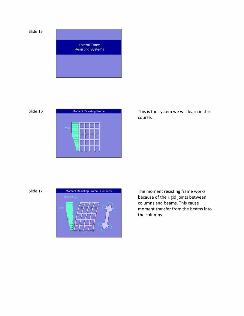
Slide 16 Moment Resisting Frame
Wind
This is the system we will learn in this
course.
Slide 17 Moment Resisting Frame - Columns
Wind
Story Drift, ∆o
The moment resisting frame works
because of the rigid joints between
columns and beams. This cause
moment transfer from the beams into
the columns.

Slide 18 Moment Resisting Frame - Columns
Moment Diagram(1st Order)
This is the resulting moment diagram
for columns in a moment resisting
frame.
Slide 19 Moment Resisting Frame
Photo courtesy of University of Washington,
Paul G, Allen Center
Slide 20 Shear Walls
Shear Walls
Shear walls are a desirable option for
many cases.
Slide 21 Shear Walls
Floor slabs act as rigid membranes, carrying lateral load to the shear walls.
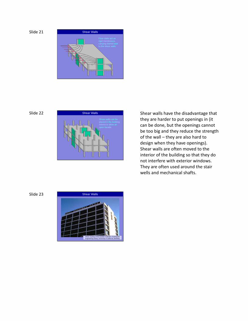
Slide 22 Shear Walls
Shear walls can be placed in the building interior to allow an open facade.
Shear walls have the disadvantage that
they are harder to put openings in (it
can be done, but the openings cannot
be too big and they reduce the strength
of the wall – they are also hard to
design when they have openings).
Shear walls are often moved to the
interior of the building so that they do
not interfere with exterior windows.
They are often used around the stair
wells and mechanical shafts.
Slide 23 Shear Walls
Photo courtesy of the Godden Collection, Earthquake Engineering Library, University of California, Berkeley

Slide 24 Shear Walls
Photo courtesy of the Godden Collection, Earthquake Engineering Library, University of California, Berkeley
Slide 25
Construction Sequence of CIP Buildings
Slide 26
Foundations (cast against earth)
Hookedbars totie intocolumns
Footings
Optimal building design starts from the
top down (we follow the load path).
Building construction necessarily begins
from the bottom up.
Step 1 (after excavation and site
grading) – Footings are cast.

Slide 27 Footings
Photo courtesy of Mehdi Setareh (VPI) and Robert Darvas (Univ. or Michigan)
Example of a pad footing (forming).
Slide 28 Wall Footings
Photo courtesy of St. Mary’s Parish,Southbridge, MA
Example of a strip footing. A strip
footing supports a wall rather than an
individual column.
Slide 29
Photo courtesy of St. Mary’s Parish,Southbridge, MA
Wall Footings

Slide 30
Photo courtesy of St. Mary’s Parish,Southbridge, MA
Wall Footings
Slide 31
Column Reinforcement
Column Forms
Columns
Lap Splice
Step 2 – The column rebar cage and
forming are put in place. Lap splice
ensure continuity of reinforcement
from the footings into the columns.
Column reinforcement will extend
through the slab above into the next
level of columns.
Slide 32 Columns
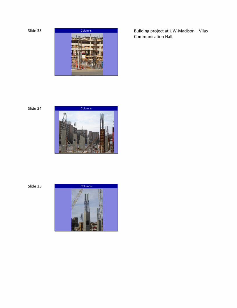
Slide 33 Columns
Building project at UW-Madison – Vilas
Communication Hall.
Slide 34 Columns
Slide 35 Columns

Slide 36 Columns
Photo courtesy of Mehdi Setareh (VPI) and Robert Darvas (Univ. or Michigan)
Casting of columns accomplished using
a pump truck.
Slide 37 Columns
This is an example of highly versatile
column formwork. These forms have a
high initial cost to purchase and must
be well maintained, but have several
advantages: (1) they are reusable; (2)
they can accommodate a wide range of
column dimensions; (3) they quality of
the interior surface will provide a good
finish; and (4) they assemble very
quickly reducing labor costs.
Slide 38
Slab on Grade
Floor Slab on Grade
Step 3 – A slab on grade is cast to
provide a surface to support formwork
and shoring.

Slide 39
Shoring
Slab &BeamForms
Slab & BeamReinforcement
Girders and Slab
Slide 40
Negative MomentReinforcement for Beam
Positive MomentReinforcement for Beam
Girders and Slab
Slide 41
Shear Reinforcement
Ties to helpanchor hookson negativemoment bars
Girders and Slab

Slide 42
Slab Reinforcement
Girders and Slab
Slide 43 Girders and Slab
Step 4 – Beams and slab are cast as a
monolithic (single) unit.
Slide 44 Columns Formed on the Next Floor

Slide 45 Formwork
Vilas Communication Center, UW-
Madison
Slide 46 Formwork
This photo shows “flying forms” (top)
and reshores (underside of slab).
Reshores are shores added after the
removal of formwork. Their purpose is
to distribute construction loads placed
on a fresh slab into slabs beneath.
Slide 47 Formwork
Another example of shoring and
formwork.

Slide 48
Photo courtesy of Mehdi Setareh (VPI) and Robert Darvas (Univ. or Michigan)
Waffle Slab Formwork & Joint
Note the congestion of the joint. There
are three directions of reinforcement
that must be accommodated at the
joint. The designer needs to think
about how all these will fit.
Intersections will be corrected by field
workers who often don’t understand
the ramifications of moving the
reinforcing bars from their intended
position.
Slide 49 Casting of Waffle Slab
Photo courtesy of Mehdi Setareh (VPI) and Robert Darvas (Univ. or Michigan)
Casting of a waffle slab. Note that
workers stand directly on the rebar and
can deform it if it is a small size.
Slide 50 Casting of Waffle Slab
Photo courtesy of Mehdi Setareh (VPI) and Robert Darvas (Univ. or Michigan)

Slide 51
Photo courtesy of Mehdi Setareh (VPI) and Robert Darvas (Univ. or Michigan)
Casting of Waffle Slab
Casting and vibration.
Slide 52 Rebar Congestion
Left – Trump Tower, Chicago, Illinois
Right – Oakland Bay Bridge, California
Both photos show intense rebar
congestion. For Trump Tower, there is a
lot of reinforcement to resist wind
loads. For Oakland Bay Bridge, the
reinforcement is to resist seismic
forces. The purple in the Oakland Bay
Bridge photo is epoxy coated
reinforcement.
Slide 53 Rebar Congestion
Reinforcement for a anchorage
segment of US 183 elevated freeway in
Austin, Texas. This photo illustrates how
complex reinforcement arrangements
can become. This particular piece of
the bridge will sit over a pier and also
anchors large steel prestressed cables.
The concentrated forces entering the
segment because of this necessitate
the large amount of reinforcement.

Slide 54 Rebar Congestion
The consequence of excessive
congestion – you may not get concrete
all the way into the forms. This segment
had to be discarded. The contractor
overcame the congestion problem by
designing a highly fluid mix that would
flow though the congested areas.