
Slide 1 Insert Company Logo Here Production Automation with Flash Programmers Gregory Czajkowski,...
39
Slide Insert Company Logo Here Production Automation with Flash Programmers Gregory Czajkowski, PhD. Elprotronic Inc. 2004 MSP430 Advanced Technical Conference
-
Upload
lindsay-dixon -
Category
Documents
-
view
212 -
download
0
Transcript of Slide 1 Insert Company Logo Here Production Automation with Flash Programmers Gregory Czajkowski,...

Slide 1
Insert Company Logo Here
Production Automation with Flash Programmers
Gregory Czajkowski, PhD.
Elprotronic Inc.
2004 MSP430 Advanced Technical Conference

Slide 2
Insert Company Logo Here
Agenda:
• Programming and Production process overview Programming
Calibration and testing
Serialization
• Testing and Calibration using Flash Programmers
• MSP430 Flash Programmers from Elprotronic JTAG, BSL and Fast BSL
DEMO – MSP430 Flash Programmer
Serialization
MSP430.DLL for debugging ( IAR-IDE, CrossWork,++ )
DLL for applications

Slide 3
Insert Company Logo Here
Programming Process Overview
• Standard Production Process: Programming
Testing
Serialization with database access and optionally with the barcode scanner
• Issues: Programmer with standard
software can be used both for programming and manual testing – usually not combined in this way
Programming
Manual Test
Serialization
Ok? No
Yes
Select unit
Repeat?
Next?
Yes
No
EndNo
Yes
Slide 4
Insert Company Logo Here
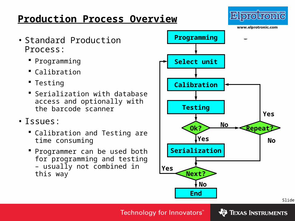
Production Process Overview
• Standard Production Process: Programming
Calibration
Testing
Serialization with database access and optionally with the barcode scanner
• Issues: Calibration and Testing are time
consuming
Programmer can be used both for programming and testing – usually not combined in this way
Programming
Calibration
Testing
Serialization
Ok? No
Yes
Select unit
Repeat?
Next?
Yes
No
EndNo
Yes

Slide 5
Insert Company Logo Here
Production Process with a Fast Programmer
Programming
Calibration
Testing
Serialization
Ok?No
Yes
Select unit
Repeat?
Next?
Yes
No
End
No
Yes
Programming
Manual Test
Serialization
Ok?No
Yes
Select unit
Repeat?
Next?
Yes
No
EndNo
Yes
Standard SoftwareCustomer’s Software
+ API-DLL

Slide 6
Insert Company Logo Here
Production Process with standard software
• Have programming, testing and serialization be consecutive tasks
• Must have: A fast programmer with an
activation of the application program possibility
Standard programming software
JTAG and/or BSL access to the MSP430Fxx target device
Programming
Manual Test
Serialization
Ok?No
Yes
Select unit
Repeat?
Next?
Yes
No
EndNo
Yes

Slide 7
Insert Company Logo Here
Production Process with API-DLL
• Have programming, calibration, testing and serialization be consecutive tasks
• Must have: A fast programmer
Programmer’s DLL library and automated test software
JTAG and/or BSL access to the MSP430Fxx target device
Programming
Calibration
Testing
Serialization
Ok? No
Yes
Select unit
Repeat?
Next?
Yes
No
End
No
Yes

Slide 8
Insert Company Logo Here
Test and Calibration Bench
Equipment
Under Test
EUT(with MSP430Fxx)
Personal
Computer
Test Equipment Bus - HPIB, USB, …
Test Equipment 1
Test Equipment 2
Test Equipment 3
Test Equipment N
EUT-PC
JTAG
BSL
RS485
IrDa
…..
BUS
Slide 9
Insert Company Logo Here
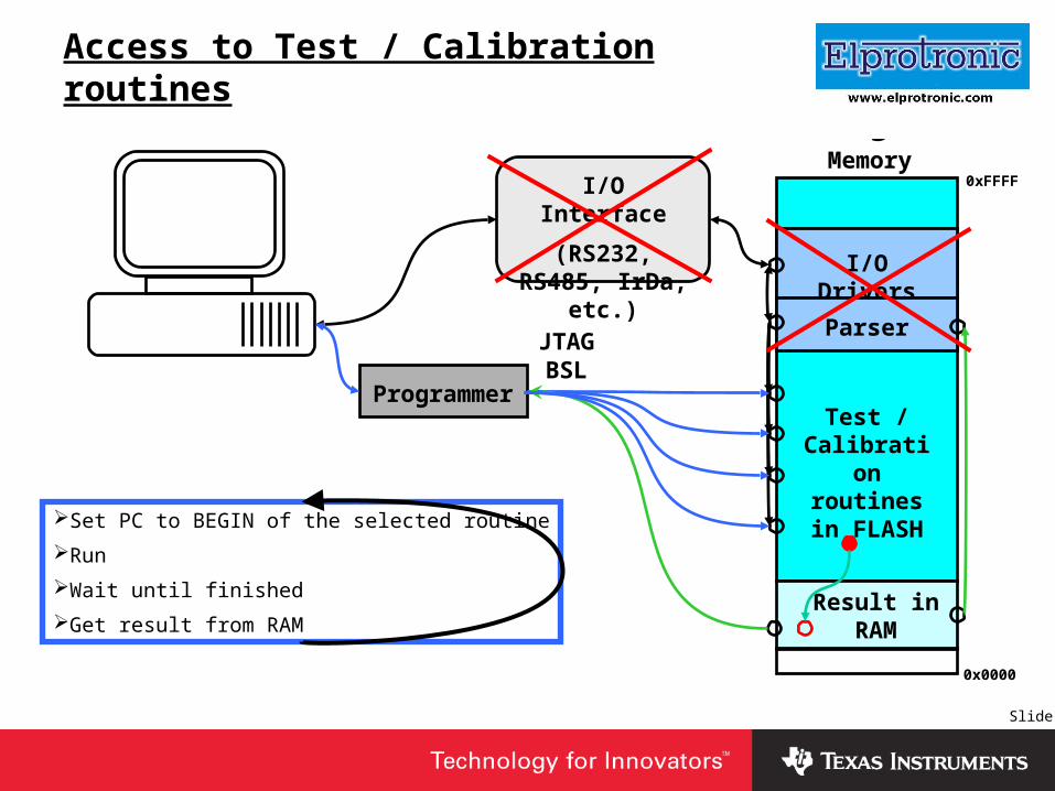
Access to Test / Calibration routines
Programmer
JTAGBSL
Test / Calibration routines in
FLASH
Result in RAM
I/O Drivers
I/O Interface
(RS232, RS485, IrDa, etc.)
Parser
Set PC to BEGIN of the selected routine
Run
Wait until finished
Get result from RAM
Memory0xFFFF
0x0000

Slide 10
Insert Company Logo Here
Test and Calibration Using Flash Programmer
0xFFFF
0x1000
0x0200
0x1100
0x0C00
0x0000
FLASH Main Memory
FLASH Info Memory
RAM
JTAG or BSL communication is required only to run a test or calibration routines
Ignore standard RESET and program startup Ignore all interrupts. Do not use interrupt
vectors.Disable watchdogDo not use RAM location 0x200 to 0x21F. It is
used by BSL.Download the test or calibration routine into
the RAM or part of the FLASH. Erase required FLASH memory segments if required.
Set the Program Counter and run program from PC location
Make a test or calibrationSave the test or calibration result in RAMRead test or calibration results from RAM
using JTAG or BSL accessPeripherals
ROM
0x0220

Slide 11
Insert Company Logo Here
Test or Calibration Routines in FLASH memory
JTAG or BSL Initialization
Download test / calibration program
Set PC to routine N address via JTAG/BSL and run MCU
Save test / calibration result in FLASH
-----------------------------------------------
ORG 01100h ;Program Start
-----------------------------------------------
initMSP: mov.w #0A00h,SP ;Init stack pointer
mov.w #WDTPW+WDTHOLD,&WDTCTL ;Stop WDT
……………………………………
ret
routine1: call #initMSP
……………………………………
routine2: call #initMSP
……………………………………
stop: jmp stop
----------------------------------------------
ORG 0FF00h ;Routine Vectors
----------------------------------------------
jmp routine1 ;0xFF00 – routine 1 start
jmp routine2 ;0xFF04 – routine 2 start
jmp routine3 ;0xFF08 – routine 3 start
jmp routine4 ;0xFF06 – routine 2 start
……………………………………
Make a test
Set Test equipments to make a test of the EUT using routine N
Get test result from RAM and Test equipments
next routineYES
NO

Slide 12
Insert Company Logo Here
Test or Calibration Routine in RAM
JTAG or BSL Initialization
Set PC to 0x220 via JTAG/BSL and run MCU
Save test / calibration result in FLASH Info Memory
---------------------------------------------------
ORG 0220h ;Routine Program Start in RAM
---------------------------------------------------
START: call #initMSP
……………………………………
………………………… ;test routine
……………………………………
stop: jmp stop
……………………………………
---------------------------------------------------
ORG 1100h ;Routine Program in FLASH
---------------------------------------------------
initMSP: mov.w #0A00h,SP ;Init stack pointer
mov.w #WDTPW+WDTHOLD,&WDTCTL ;Stop WDT
………………………….................
ret
Make a test
Set Test equipments to make a selected test of the EUT
Get test result from RAM and Test equipments
next routineYES
NO
Write routine code to RAM via JTAG/BSL

Slide 13
Insert Company Logo Here
Flash Programmers From Elprotronic
Main Features
Includes JTAG and BSL interfaces in one package
Support all MSP430Fxx devices
Fast Flash programming
– 60 kBytes Flash can be programmed in 2.3 s via JTAG
– 60 kBytes Flash can be programmed in 5 s via BSL
Target device can be supplied from programming adapter 3.3V / 130mA
Access to Flash and RAM memory
PC can be set and MCU can jump to test / calibration routine
Serialization with data base
Automatic serialization
Manual serialization
Serialization using barcode scanner

Slide 14
Insert Company Logo Here
Fast MSP430 JTAG / BSL Programmers
USB version Parallel Port version==== JTAG ==== ( FlashPro430 )
JTAG Communication speed ………………… up to 4, 1 , 0.4 Mb/s up to 3Mb/sProgramming speed …………………………… 29 kBytes / s 20 kBytes / sTotal Flash programming time …....………….. 2.3 seconds 3.8 seconds ( 60 kBytes )Autoprogram time ( erase, program, verify) ….. 3.7 seconds 5.0 seconds ( 60 kBytes )Burn JTAG Fuse ………………........................ Yes ( 0.3 s ) Yes ( 0.7 s )MSP430.DLL – for debugging ( IAR-IDE, ++ ). YES Coming soonOthers Multi USB-FPA
All MSP430 Flash Devices supported.
JTAG and BSL in one package.
API-DLL.
Serial Number assign capability.
Model / Revision assign capability.
==== BSL =====
BSL communication speed ……………….…… 350 or 9.6 kb/s 300, 75, 9.6 kb/s
Total Flash programming time …….......…….. 5 seconds 6.5 seconds ( 60 kBytes )
Autoprogram time ( erase, program, verify) ….. 6.5 seconds 7.5 seconds ( 60 kBytes )

Slide 15
Insert Company Logo Here
Flash Programming through Fast BSL
Password verification ……………………… BSL 0.2 sDownload Fast BSL into RAM ……………… BSL 0.3 sFast BSL verification ………………………… BSL 0.3 sDCO adjustment ……………………………… FBSL 0.2 sFlash programming (60kB Flash) …………… FBSL 3-4 sFast verification ………………………………… FBSL 0.5 sCheck Sum calculation ……………………… FBSL 0.5 s
Total time = 5-6 s
Programming time (60kB Flash size)
via Fast BSL – 350 kb/s - 6 s
Standard BSL – 38.4 kb/s - > 24 s
Standard BSL – 9.6 kb/s - > 82 s
I / ORAM ( FBSL )
ROM (BSL)
FLASH
0x0000
0x0200
0x0300
0x0c00
0x1000
0xFFFF
RAM
Fast BSL code size in RAM – 220 bytesNote: Only few types of the MSP430Fxx
with RAM size 128 bytes cannot utilize FBSL.
MCU with small RAM can be programmed
via standard BSL (9.6kb/s).
Slide 16
Insert Company Logo Here
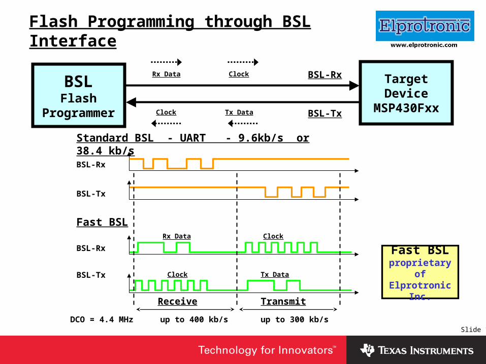
Flash Programming through BSL Interface
TargetDevice
MSP430Fxx
BSLFlash
Programmer
BSL-Rx
BSL-Tx
Standard BSL - UART - 9.6kb/s or 38.4 kb/s
BSL-Rx
BSL-Tx
BSL-Rx
BSL-Tx
Fast BSL
Receive Transmit
up to 400 kb/s up to 300 kb/sDCO = 4.4 MHz
Rx Data
Tx Data
Clock
Clock
Rx Data
Clock Tx Data
Clock
Fast BSLproprietary of
Elprotronic Inc.

Slide 17
Insert Company Logo Here
JTAG / BSL combined connector
Vcc
Vcc Ext
TEST / Vpp
nc
nc nc
RST
GND
TCK
TMS
TDI / Vpp
TDO / TDI
TCK
RST
Vcc
Vcc Ext
nc nc
TEST
GND
BSL-Rx
BSL-Tx
Vcc / *Vcc Sense
Vcc Ext
TEST / Vpp
*BSL-Tx
*BSL-Rx
TDO / TDI
TDI / Vpp
TMS
TCK
GND
RST
*GND (Tx/Rx shield)
JTAG / BSL
TI - JTAG
TI - BSL
2 1
2 1
2 1
14 13
14 13
10 9

Slide 18
Insert Company Logo Here
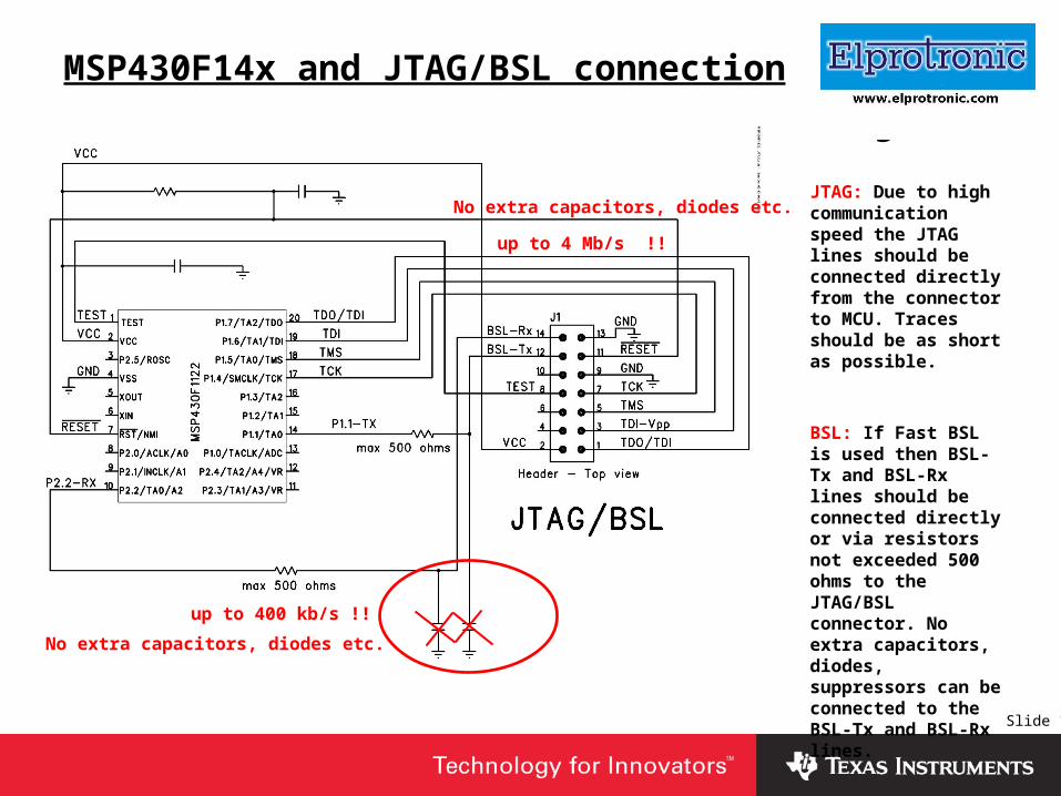
MSP430F14x and JTAG/BSL connection
up to 4 Mb/s !!
up to 400 kb/s !!
No extra capacitors, diodes etc.
No extra capacitors, diodes etc. JTAG: Due to high communication speed the JTAG lines should be connected directly from the connector to MCU. Traces should be as short as possible.
BSL: If Fast BSL is used then BSL-Tx and BSL-Rx lines should be connected directly or via resistors not exceeded 500 ohms to the JTAG/BSL connector. No extra capacitors, diodes, suppressors can be connected to the BSL-Tx and BSL-Rx lines.
Slide 19
Insert Company Logo Here
MSP430F14x and JTAG/BSL connection
up to 4 Mb/s !!
up to 400 kb/s !!
No extra capacitors, diodes etc.
No extra capacitors, diodes etc.JTAG: Due to high communication speed the JTAG lines should be connected directly from the connector to MCU. Traces should be as short as possible.
BSL: If Fast BSL is used then BSL-Tx and BSL-Rx lines should be connected directly or via resistors not exceeded 500 ohms to the JTAG/BSL connector. No extra capacitors, diodes, suppressors can be connected to the BSL-Tx and BSL-Rx lines.
Slide 20
Insert Company Logo Here
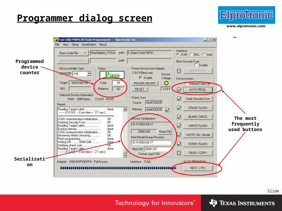
Programmer dialog screen
The most frequently used
buttons
Programmed device counter
Serialization

Slide 21
Insert Company Logo Here
Programmer serialization dialog screen
Specify file name and location, where the serialization’s data base should be saved
Specify location in FLASH, where the Serial Number is saved
Select format of the automatically created Serial Number
Model, Group, Revision specification – similar to SN

Slide 22
Insert Company Logo Here
Serialization with Barcode Scanner
Programmer
JTAGBSL
Target Device

Slide 23
Insert Company Logo Here
SN and Model space definition
0xFED0: .. .. .. .. .. .. .. .. .. .. .. .. .. .. .. .. | ................
0xFEE0: .. .. .. .. .. .. .. .. .. .. .. .. .. .. .. .. | ................
0xFEF0: 44 65 6D 6F 2D 31 20 20 41 54 43 2D 32 30 30 34 | Demo-1 ATC-2004
0xFF00: FF FF FF FF FF FF FF FF 53 6F 66 74 77 61 72 65 | ........Software
0xFF10: 20 4C 61 62 65 6C 2D 2D 31 32 33 34 35 36 37 38 | Label--12345678
0xFF20: FF FF FF FF FF FF FF FF FF FF FF FF FF FF FF FF | ................
0xFF30: 31 40 00 0A 35 40 00 02 B2 40 80 5A 20 01 85 43 | [email protected]@[email protected] ..C
0xFF40: 00 00 25 53 35 90 00 04 FA 2B C2 43 21 00 C2 43 | ..%S5....+.C!..C
0xFF50: 29 00 C2 43 19 00 C2 43 1D 00 C2 43 31 00 C2 43 | )..C...C...C1..C
0xFF60: 35 00 C2 43 22 00 C2 43 26 00 C2 43 2A 00 C2 43 | 5..C"..C&..C*..C
0xFF70: 2E 00 C2 43 1A 00 C2 43 1B 00 C2 43 1E 00 C2 43 | ...C...C...C...C
0xFF80: 1F 00 C2 43 32 00 C2 43 33 00 C2 43 36 00 C2 43 | ...C2..C3..C6..C
0xFF90: 37 00 FF 3F 00 13 .. .. .. .. .. .. .. .. .. .. | 7..?............
;-----------------------------ORG 0xFEF0
;-----------------------------; 1234567890123456' DB 'Demo-1 ATC-2004';----------------------------- ORG 0xFF00;-----------------------------SERIAL_NUMBER: DW 0xFFFF,0xFFFF,0xFFFF,0xFFFFSOFTWARE_LABEL: DB 'Software Label--12345678';----------------------------- ORG 0xFF20;-----------------------------MODEL_GR_REV: DW 0xFFFF,0xFFFF,0xFFFF,0xFFFF DW 0xFFFF,0xFFFF,0xFFFF,0xFFFF
EVENRESET: mov #STACK_ADDR,SP ;Initialize stack pointer
Source code
Code Data view
Definition of the empty area in code for serial number and model assignment.
DW 0xFFFF, 0xFFFF, ………
or
DB 0xFF,0xFF, ………
Result -> Defined data 0xFF in code.
NOT recommended !

Slide 24
Insert Company Logo Here
SN and Model space definition - continue
0xFED0: .. .. .. .. .. .. .. .. .. .. .. .. .. .. .. .. | ................
0xFEE0: .. .. .. .. .. .. .. .. .. .. .. .. .. .. .. .. | ................
0xFEF0: 44 65 6D 6F 2D 31 20 20 41 54 43 2D 32 30 30 34 | Demo-1 ATC-2004
0xFF00: .. .. .. .. .. .. .. .. 53 6F 66 74 77 61 72 65 | ........Software
0xFF10: 20 4C 61 62 65 6C 2D 2D 31 32 33 34 35 36 37 38 | Label--12345678
0xFF20: .. .. .. .. .. .. .. .. .. .. .. .. .. .. .. .. | ................
0xFF30: 31 40 00 0A 35 40 00 02 B2 40 80 5A 20 01 85 43 | [email protected]@[email protected] ..C
0xFF40: 00 00 25 53 35 90 00 04 FA 2B C2 43 21 00 C2 43 | ..%S5....+.C!..C
0xFF50: 29 00 C2 43 19 00 C2 43 1D 00 C2 43 31 00 C2 43 | )..C...C...C1..C
0xFF60: 35 00 C2 43 22 00 C2 43 26 00 C2 43 2A 00 C2 43 | 5..C"..C&..C*..C
0xFF70: 2E 00 C2 43 1A 00 C2 43 1B 00 C2 43 1E 00 C2 43 | ...C...C...C...C
0xFF80: 1F 00 C2 43 32 00 C2 43 33 00 C2 43 36 00 C2 43 | ...C2..C3..C6..C
0xFF90: 37 00 FF 3F 00 13 .. .. .. .. .. .. .. .. .. .. | 7..?............
;---------------------------------ORG 0xFEF0
;---------------------------------; 1234567890123456' DB 'Demo-1 ATC-2004';--------------------------------- ORG 0xFF00;---------------------------------SERIAL_NUMBER: DS 8SOFTWARE_LABEL: DB 'Software Label--12345678';--------------------------------- ORG 0xFF20;---------------------------------MODEL_GR_REV: DS 16
EVENRESET: mov #STACK_ADDR,SP ;Initialize stack pointer
Source code
Code Data view
Definition of the empty area in code for serial number and model assignment.
DS number of bytes
Result -> Defined no data in code.
Recommended !

Slide 25
Insert Company Logo Here
Serialization Statistics

Slide 26
Insert Company Logo Here
MSP430.DLL
MSP430.DLL library allows use the USB programming adapter like FET (Flash Emulation Tool) with the IAR, Quadravox or CrossStudio IDE debugging software.
Performance of the USB-MSP430-FPA with the MSP430.DLL (as a FET) in debugging environment.
1 Flash Programming Time ( 60kB ) 5 seconds
2 Flash Erasing Time ( All Memory ) 0.3 s
3 Scrolling Memory Window Time from address 0x0000 to 0xFFFF ( PgDn - page by page )
6 seconds
4 Single step debugging speed 15 steps per second
Note: * All times are typical - tested with the IAR Embedded Workbench IDE software.

Slide 27
Insert Company Logo Here
DLL for application
After installing the USB-MSP430 Flash Programmer the DLL software and demo can be found in the following directory:
C:\Program Files\Elprotronic\USB MSP430 Flash Programmer
API-DLL
API-DLL-Demo
Cpp
VB6
VBnet
Fast MSP430 Flash Programmer (USB or Parallel Port) can be remotely controlled from other software applications (Visual C++, Visual Basic, LabView etc.) via DLL library (perfect for production usage).
• Note: API-DLL library has the same list of functions for the USB and the Parallel Port Programmers version.

Slide 28
Insert Company Logo Here
DLL function type
Following three group of the function are implemented in the DLL:
Generic function• Initialize programmer, download code files, configuration setup etc.
Encapsulated functions• Executed full selected task with the target device starting from the power up of the target device, communication initialization, selected function execute and finished with the power down of the target device.
• No interruption and modification of the function can be done.
• Easy to use, optimized for fast execution.
Sequential functions• Open target device function is called first
• Any combination of small task can be selected like write word, read word, write block, erase flash segment, blank check part of memory etc.
• Access to the RAM
• Enforce program execution from any location – set PC and run
• Close target device function at the end

Slide 29
Insert Company Logo Here
DLL functions
Generic Functions
DLL Software ID
Adapter Initialization
Read Configuration File
Configuration Setup
Read Code File
Read Password File
Power Target Device
Reset Target Device
Report Message
………more ………….
status = F_DLLTypeVer( );
……………………………….
status = F_Initialization( );
status = F_ConfigFileLoad( FileName );
status = F_ReadCodeFile( Format, FileName);
START
Programming procedures
Initialization
Example in C++

Slide 30
Insert Company Logo Here
DLL Functions
Encapsulated Functions
Auto Program
Fuse or Password Verification
Erase Flash Memory
Blank Check Flash Memory
Write Flash Memory
Read Flash Memory
Verify Flash Memory
1. Target’s Device Power ON;
2. Power ON Vcc verification;
3. JTAG or BSL communication initialization;
4. Target’s Device DCO tune if required;
5. Selected Encapsulated Function execution;
6. JTAG or BSL communiaction termination;
7. Target’s Device Power OFF;
Functions StructureFuse or Password Verification
Erase Flash Memory
Blank Check Flash Memory
Program Flash Memory
Verify Flash Memory
JTAG Fuse Blow ( if enabled )

Slide 31
Insert Company Logo Here
Encapsulated DLL Function - EXAMPLE
do { // do .. while loop
status = F_Autoprogram ( 0 ); // Encapsulated DLL function.
// Vcc ON, JTAG/BSL Init, Erase, Blank check, Program, Verify, Vcc OFF.
if ( status == TRUE ) // check of F_Autoprogram finished successfully
{ ………….. // -- optional --
Serialization ( ); // serialization or other procedure
…………... // -- optional ---
}
else
{ ……. } // programming error !!!
if ( next_unit ( ) == FALSE ) break; // exit if last unit has been programmed
} while (1); // end of loop
……………………………….
Initialization
Slide 32
Insert Company Logo Here
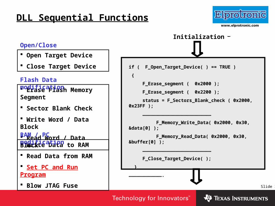
DLL Sequential Functions
if ( F_Open_Target_Device( ) == TRUE )
{
F_Erase_segment ( 0x2000 );
F_Erase_segment ( 0x2200 );
status = F_Sectors_Blank_check ( 0x2000, 0x23FF );
…………………………………………………………………
F_Memory_Write_Data( 0x2000, 0x30, &data[0] );
F_Memory_Read_Data( 0x2000, 0x30, &buffer[0] );
…………………………………………………………………
F_Close_Target_Device( );
}
……………………………….
Initialization
Open Target Device
Close Target Device
Erase Flash Memory Segment
Sector Blank Check
Write Word / Data Block
Read Word / Data Block
Write Data to RAM
Read Data from RAM
Set PC and Run Program
Blow JTAG Fuse
Open/Close
Flash Data modification
RAM / PC modification

Slide 33
Insert Company Logo Here
API-DLL Demo Dialog Screen
F_Autoprogram( 0 );
F_VerifyFuseorPassword( );
F_Memory_Blank_Check( 0 );
F_Memory_Write( 0 );
F_Memory_Verify( 0 );
F_Memory_Read( &buffer[0] );
F_Memory_Erase( 0 );
F_ReportMessage( &text[0] );
F_Initialization( ); F_ReadCodeFile( FORMAT, FilePathAndName );
F_Memory_Write_Data( start_address, size, &buffer[0] );
F_Memory_Read_Data( start_address, size, &buffer[0] );
status = F_name…….…..;
status = TRUE, FALSE, ….
F_GetSetup( &config ) ;
config.Interface =
INTERFACE_JTAG;
F_ConfigSetup( config ) ;
F_Set_Pc_And_Run( 0x400 );

Slide 34
Insert Company Logo Here
demo
API-DLL – Set PC and Run Example
1. Init target device
2. Write data to RAM address 0x440 -> 21 22 23 24 25 26 27 28
3. Read data from RAM address 0x440 -> 21 22 23 24 25 26 27 28
4. Write program to Ram address 0x400
ORG 0x400
Test: mov #WDTPW+WDTHOLD, &WDTCTL ;Stop WDT
mov #0x3412,&TestData
mov #0x7856,&(TestData+2)
mov #0xbc9A,&(TestData+4)
mov #0xf0DE,&(TestData+6)
Idle: jmp Idle
ORG 0x440
TestData:
DW 0,0,0,0
5. Set PC to 0x400 and RUN
6. Init Target device
7. Read data from RAM address 0x440 -> 12 34 56 78 9a bc de f0

Slide 35
Insert Company Logo Here
Test / Calibration / Programming via JTAG / BSL
JTAG or BSL Initialization
Download test / calibration program
Reset MCU and run test / calibration program
Store test / calibration result in RAM
Read test / calibration result from RAM
Download final application code to flash memory
Write calibration data and serial number to flash
END
DLL - Autoprogram – 60kB in 3.5 ( 7) s
Wait until finished. Time not specified.
DLL – Read RAM
Note: Time - JTAG ( BSL )
DLL - Autoprogram – 60kB in 3.5 ( 7) s
DLL – Write data / Read data
Blow JTAG fuse ( via JTAG communication only )DLL – Blow fuse - 0.3 s
Slide 36
Insert Company Logo Here
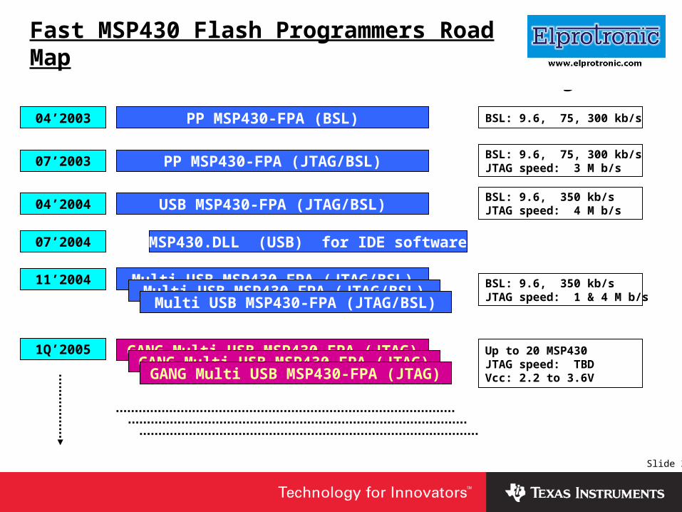
Fast MSP430 Flash Programmers Road Map
PP MSP430-FPA (BSL)
PP MSP430-FPA (JTAG/BSL)
USB MSP430-FPA (JTAG/BSL)
MSP430.DLL (USB) for IDE software
Multi USB MSP430-FPA (JTAG/BSL)
04’2003
07’2003
04’2004
07’2004
11’2004
1Q’2005
BSL: 9.6, 75, 300 kb/s
BSL: 9.6, 75, 300 kb/sJTAG speed: 3 M b/s
BSL: 9.6, 350 kb/sJTAG speed: 4 M b/s
BSL: 9.6, 350 kb/sJTAG speed: 1 & 4 M b/s
Up to 20 MSP430 JTAG speed: TBD Vcc: 2.2 to 3.6V
GANG Multi USB MSP430-FPA (JTAG)
Multi USB MSP430-FPA (JTAG/BSL)Multi USB MSP430-FPA (JTAG/BSL)
GANG Multi USB MSP430-FPA (JTAG)GANG Multi USB MSP430-FPA (JTAG)

Slide 37
Insert Company Logo Here
Multi USB-MSP430-FPA
Programmer
USB-FPA-1
Target Device
USB-FPA-2
USB-FPA-3
USB-FPA-8
GANG

Slide 38
Insert Company Logo Here
Conclusion
• Fast MSP430 Flash Programmers from Elprotronic can simplify production process and can be used for: Flash programming
Accessing test and calibration routines
Serialization

Slide 39
Insert Company Logo Here
Questions?