SLENDER STEEL ARCHES WITH PARTICULAR … Steel Arches... · SLENDER STEEL ARCHES WITH PARTICULAR...
10
Arch Bridges ARCH´04 P. Roca and E. Oñate (Eds) CIMNE, Barcelona, 2004 1 SLENDER STEEL ARCHES WITH PARTICULAR HANGER ARRANGEMENT FOR MODERNISING CONCRETE BRIDGES (ARCH´04) Ph. Van Bogaert * , W. De Corte * , B. De Pauw * and H. De Backer * * Civil Engineering Department Ghent University Technologiepark 904, B 9052 Gent, Belgium e-mail: [email protected], web page: http://awww.Ugent.be Key words: steel tied arch, patch load, arch hanger arrangement, modernization of viaducts Abstract. Slender steel arches, with particular hanger arrangement, may constitute a structural solution for modernizing existing viaducts, as demonstrated through the design concept of the removal of 3 piers from a multi-span concrete viaduct. A suspension system, consisting of a steel tied arch has been proposed for resisting the superstructure reactions. However, this steel arch is heavily subjected to patch loading near its crown and its springs. After adopting a fan position of the hangers and varying of the hanger slope, the arch bending becomes more homogeneous, the patch load being resisted more adequately by a sloping hanger arrangement. An optimum hanger slope may be found at which the change in bending curvature at the arch crown changes from sagging to hogging. The arch deflections of the system are lowered considerably and are consistent with the conclusions for arch bending.
Transcript of SLENDER STEEL ARCHES WITH PARTICULAR … Steel Arches... · SLENDER STEEL ARCHES WITH PARTICULAR...
Arch Bridges ARCH´04
P. Roca and E. Oñate (Eds) CIMNE, Barcelona, 2004
1
SLENDER STEEL ARCHES WITH PARTICULAR HANGER ARRANGEMENT FOR MODERNISING CONCRETE BRIDGES
(ARCH´04)
Ph. Van Bogaert*, W. De Corte*, B. De Pauw * and H. De Backer* * Civil Engineering Department
Ghent University Technologiepark 904, B 9052 Gent, Belgium
e-mail: [email protected], web page: http://awww.Ugent.be
Key words: steel tied arch, patch load, arch hanger arrangement, modernization of viaducts
Abstract. Slender steel arches, with particular hanger arrangement, may constitute a structural solution for modernizing existing viaducts, as demonstrated through the design concept of the removal of 3 piers from a multi-span concrete viaduct. A suspension system, consisting of a steel tied arch has been proposed for resisting the superstructure reactions. However, this steel arch is heavily subjected to patch loading near its crown and its springs. After adopting a fan position of the hangers and varying of the hanger slope, the arch bending becomes more homogeneous, the patch load being resisted more adequately by a sloping hanger arrangement. An optimum hanger slope may be found at which the change in bending curvature at the arch crown changes from sagging to hogging. The arch deflections of the system are lowered considerably and are consistent with the conclusions for arch bending.
Ph. Van Bogaert, W. De Corte, B. De Pauw, H. De Backer.
2
1 INTRODUCTION
Slender steel arches with particular hanger arrangement, may constitute a structural solution for reinforcing or modernising existing bridges or viaducts, which must be kept in operation at all times. This may be demonstrated through the design concept of the transformation of a multi-span concrete viaduct.
Urban developments have caused that in many cities, railways are entering the central area towards stations. Thus railway lines are crossing densely populated parts of cities, often on elevated viaducts. The public perception of these multi-span viaducts has now become rather bad. They constitute a disturbing view and the places created below, initially intended for car parking, are seen as a waste of valuable open space. Mainly the multiple piers are a hindrance to rearranging of subjacent roads or urban development.
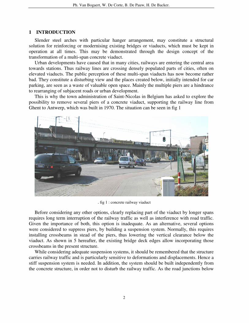
This is why the town administration of Saint-Nicolas in Belgium has asked to explore the possibility to remove several piers of a concrete viaduct, supporting the railway line from Ghent to Antwerp, which was built in 1970. The situation can be seen in fig 1
. fig 1 : concrete railway viaduct
Before considering any other options, clearly replacing part of the viaduct by longer spans requires long term interruption of the railway traffic as well as interference with road traffic. Given the importance of both, this option is inadequate. As an alternative, several options were considered to suppress piers, by building a suspension system. Normally, this requires installing crossbeams in stead of the piers, thus lowering the vertical clearance below the viaduct. As shown in 5 hereafter, the existing bridge deck edges allow incorporating those crossbeams in the present structure.
While considering adequate suspension systems, it should be remembered that the structure carries railway traffic and is particularly sensitive to deformations and displacements. Hence a stiff suspension system is needed. In addition, the system should be built independently from the concrete structure, in order not to disturb the railway traffic. As the road junctions below
Ph. Van Bogaert, W. De Corte, B. De Pauw, H. De Backer.
3
the viaduct are important access roads to the town centre, the system should have some aesthetic value and it may stress the fact that there is a discontinuity in the structure. All these requirements may be answered by an arch structure, of the type shown in fig 2, the top being a perspective view of the existing viaduct.
Fig 2 : proposal for suspension system It may be seen that 3 piers can be removed. The reactions on the central pier are replaced
by a system of hangers, constituting patch loading on the arch, whereas both other piers are replaced by a short hanger system.
2 PATCH LOADING ON TIED ARCH
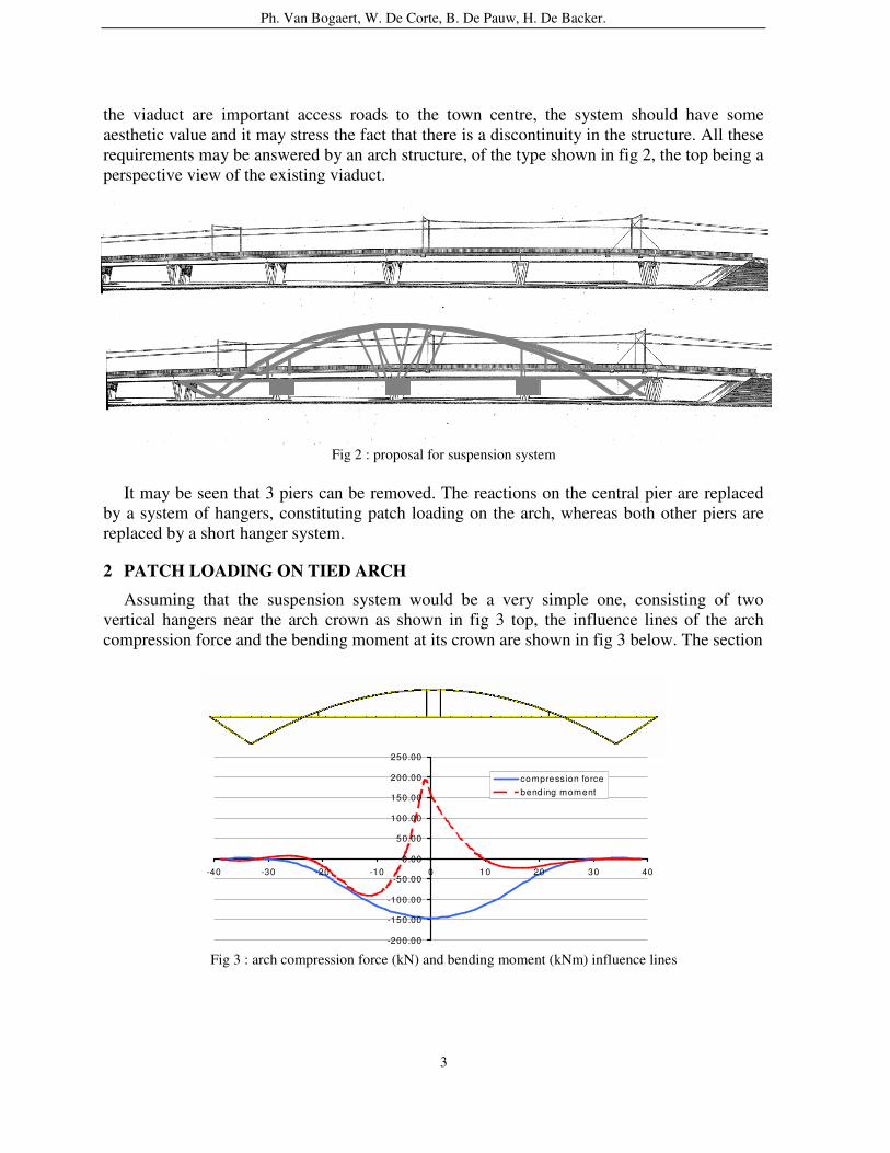
Assuming that the suspension system would be a very simple one, consisting of two vertical hangers near the arch crown as shown in fig 3 top, the influence lines of the arch compression force and the bending moment at its crown are shown in fig 3 below. The section
Fig 3 : arch compression force (kN) and bending moment (kNm) influence lines -200.00
-150.00
-100.00
-50.00
0.00
50.00
100.00
150.00
200.00
250.00
-40 -30 -20 -10 0 10 20 30 40
compression forcebending moment
Ph. Van Bogaert, W. De Corte, B. De Pauw, H. De Backer.
4
being considered is at the left hanger connection point. The arch compression force is gradually increasing along the bridge axis, whereas the bending moment has high peak values if the patch load is applied at the arch section being considered.
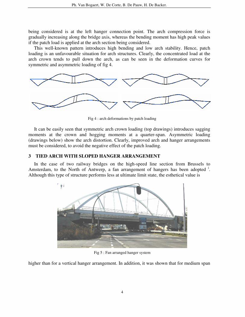
This well-known pattern introduces high bending and low arch stability. Hence, patch loading is an unfavourable situation for arch structures. Clearly, the concentrated load at the arch crown tends to pull down the arch, as can be seen in the deformation curves for symmetric and asymmetric loading of fig 4.
Fig 4 : arch deformations by patch loading It can be easily seen that symmetric arch crown loading (top drawings) introduces sagging
moments at the crown and hogging moments at a quarter-span. Asymmetric loading (drawings below) show the arch distortion. Clearly, improved arch and hanger arrangements must be considered, to avoid the negative effect of the patch loading.
3 TIED ARCH WITH SLOPED HANGER ARRANGEMENT
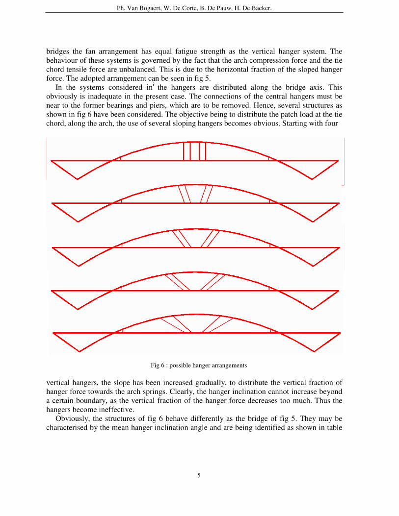
In the case of two railway bridges on the high-speed line section from Brussels to Amsterdam, to the North of Antwerp, a fan arrangement of hangers has been adopted i. Although this type of structure performs less at ultimate limit state, the esthetical value is
Fig 5 : Fan arranged hanger system
higher than for a vertical hanger arrangement. In addition, it was shown that for medium span
Ph. Van Bogaert, W. De Corte, B. De Pauw, H. De Backer.
5
bridges the fan arrangement has equal fatigue strength as the vertical hanger system. The behaviour of these systems is governed by the fact that the arch compression force and the tie chord tensile force are unbalanced. This is due to the horizontal fraction of the sloped hanger force. The adopted arrangement can be seen in fig 5.
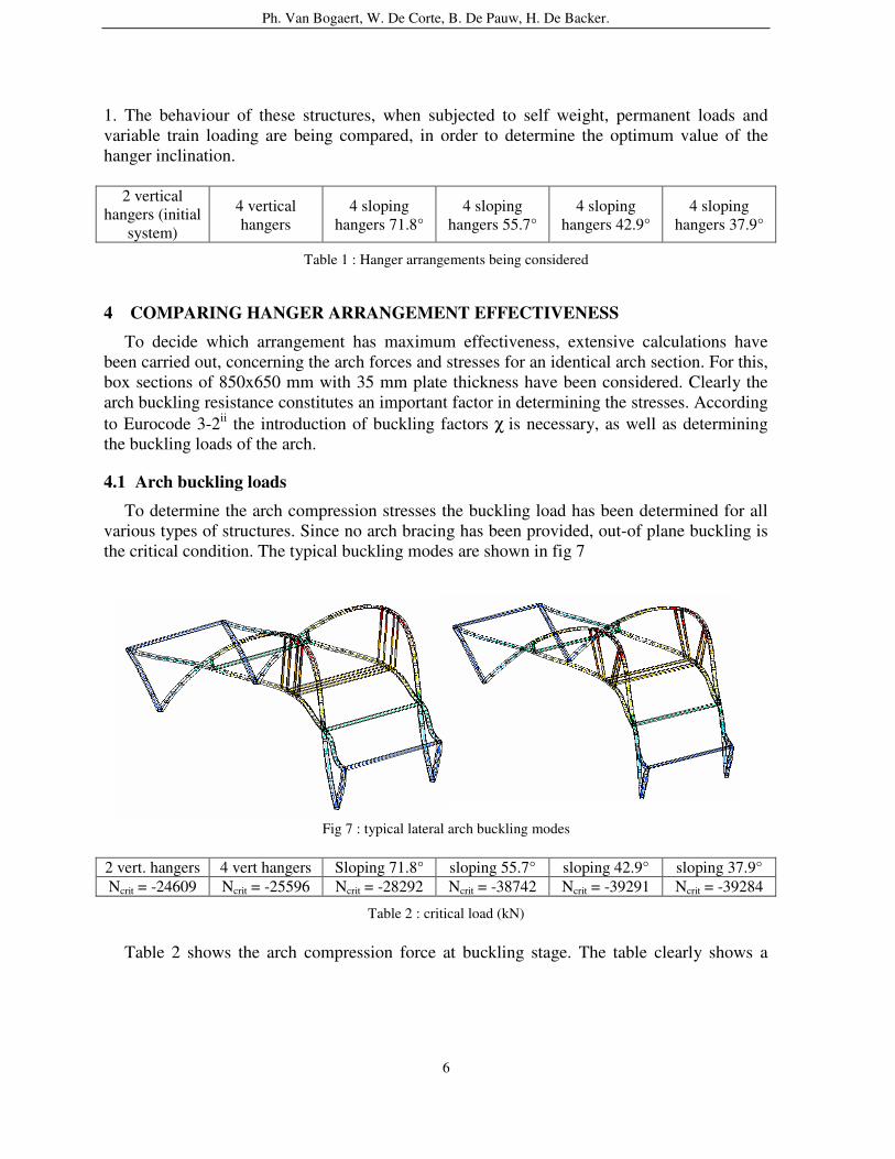
In the systems considered ini the hangers are distributed along the bridge axis. This obviously is inadequate in the present case. The connections of the central hangers must be near to the former bearings and piers, which are to be removed. Hence, several structures as shown in fig 6 have been considered. The objective being to distribute the patch load at the tie chord, along the arch, the use of several sloping hangers becomes obvious. Starting with four
Fig 6 : possible hanger arrangements
vertical hangers, the slope has been increased gradually, to distribute the vertical fraction of hanger force towards the arch springs. Clearly, the hanger inclination cannot increase beyond a certain boundary, as the vertical fraction of the hanger force decreases too much. Thus the hangers become ineffective.
Obviously, the structures of fig 6 behave differently as the bridge of fig 5. They may be characterised by the mean hanger inclination angle and are being identified as shown in table
Ph. Van Bogaert, W. De Corte, B. De Pauw, H. De Backer.
6
1. The behaviour of these structures, when subjected to self weight, permanent loads and variable train loading are being compared, in order to determine the optimum value of the hanger inclination.
2 vertical
hangers (initial system)
4 vertical hangers
4 sloping hangers 71.8°
4 sloping hangers 55.7°
4 sloping hangers 42.9°
4 sloping hangers 37.9°
Table 1 : Hanger arrangements being considered
4 COMPARING HANGER ARRANGEMENT EFFECTIVENESS
To decide which arrangement has maximum effectiveness, extensive calculations have been carried out, concerning the arch forces and stresses for an identical arch section. For this, box sections of 850x650 mm with 35 mm plate thickness have been considered. Clearly the arch buckling resistance constitutes an important factor in determining the stresses. According to Eurocode 3-2ii the introduction of buckling factors χ is necessary, as well as determining the buckling loads of the arch.
4.1 Arch buckling loads
To determine the arch compression stresses the buckling load has been determined for all various types of structures. Since no arch bracing has been provided, out-of plane buckling is the critical condition. The typical buckling modes are shown in fig 7
Fig 7 : typical lateral arch buckling modes
2 vert. hangers 4 vert hangers Sloping 71.8° sloping 55.7° sloping 42.9° sloping 37.9° Ncrit = -24609 Ncrit = -25596 Ncrit = -28292 Ncrit = -38742 Ncrit = -39291 Ncrit = -39284
Table 2 : critical load (kN)
Table 2 shows the arch compression force at buckling stage. The table clearly shows a
Ph. Van Bogaert, W. De Corte, B. De Pauw, H. De Backer.
7
constant increasing of the buckling load with decreasing of the hanger slope. The hangers tend to stabilise the buckling phenomenon. From the buckling load, an equivalent buckling length may be derived as :
lc = π E I Pcrit
(1)
Or alternatively, the relative slenderness may be found from :
λrel = λ / λE = fyd APcrit
(2)
Equations (1) and (2) enable the application of the classical stress calculation as mentioned
in EC 3-2. It may be noticed that the analysis is based on the use of buckling curves, which take into account silently the existence of arch imperfections. However, the curves have mainly been established for straight column members and appear too conservative for out-of-plane arch buckling. The authors are starting a research concerning real arch imperfections by highly-sensitive strain measurements. A first result was obtained on the 2 structures of fig 5, demonstrating a maximum out-of-plane arch imperfection of 12 mm for 60 m arch span.
4.2 Arch stresses
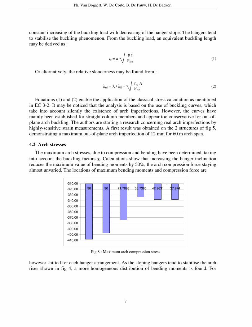
The maximum arch stresses, due to compression and bending have been determined, taking into account the buckling factors χ. Calculations show that increasing the hanger inclination reduces the maximum value of bending moments by 50%, the arch compression force staying almost unvaried. The locations of maximum bending moments and compression force are
Fig 8 : Maximum arch compression stress
however shifted for each hanger arrangement. As the sloping hangers tend to stabilise the arch rises shown in fig 4, a more homogeneous distribution of bending moments is found. For
-410.00
-400.00
-390.00
-380.00
-370.00
-360.00
-350.00
-340.00
-330.00
-320.00
-310.0090 90 71.7896 55.7365 42.9631 37.974
Ph. Van Bogaert, W. De Corte, B. De Pauw, H. De Backer.
8
small slope angles, this effect is counteracted partly by the heavier effect of asymmetric loading. Fig 8 shows the largest arch compression stresses for the various arrangements being considered. From this, it may be concluded that the arrangement with average hanger slope of 55.7° performs best. It corresponds to the 3rd structure shown in fig 6.
4.3 Arch deformation
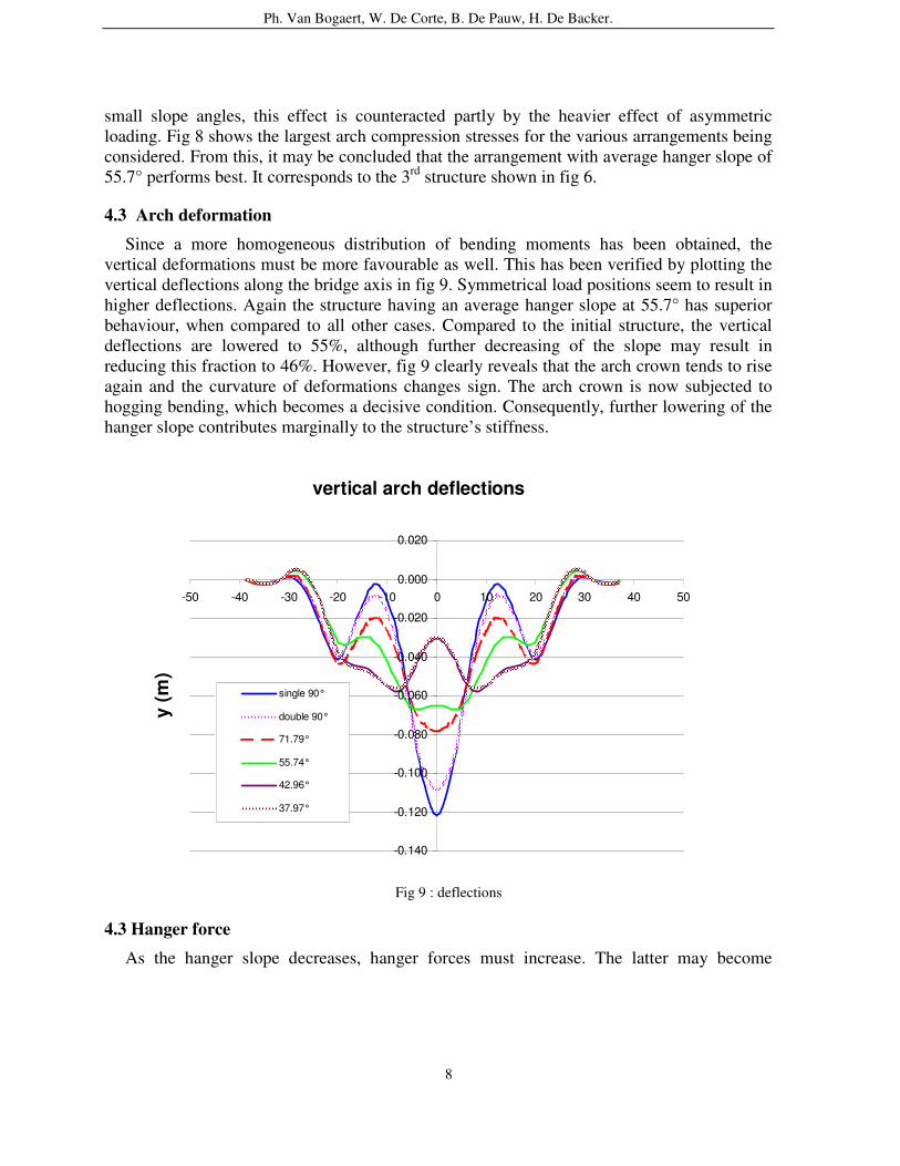
Since a more homogeneous distribution of bending moments has been obtained, the vertical deformations must be more favourable as well. This has been verified by plotting the vertical deflections along the bridge axis in fig 9. Symmetrical load positions seem to result in higher deflections. Again the structure having an average hanger slope at 55.7° has superior behaviour, when compared to all other cases. Compared to the initial structure, the vertical deflections are lowered to 55%, although further decreasing of the slope may result in reducing this fraction to 46%. However, fig 9 clearly reveals that the arch crown tends to rise again and the curvature of deformations changes sign. The arch crown is now subjected to hogging bending, which becomes a decisive condition. Consequently, further lowering of the hanger slope contributes marginally to the structure’s stiffness.
Fig 9 : deflections
4.3 Hanger force
As the hanger slope decreases, hanger forces must increase. The latter may become
vertical arch deflections
-0.140
-0.120
-0.100
-0.080
-0.060
-0.040
-0.020
0.000
0.020
-50 -40 -30 -20 -10 0 10 20 30 40 50
y (m
)
single 90°
double 90°
71.79°
55.74°
42.96°
37.97°
Ph. Van Bogaert, W. De Corte, B. De Pauw, H. De Backer.
9
compression forces in some cases and load combinations. For the various structures being considered, maximum and minimum hanger forces have been determined in table 3. The table displays that tensile forces in the single vertical hanger system are larger than in the four hanger systems. However if the hanger slope is lower than xx°, the force again reaches beyond the value from the initial structure. In addition, some values become negative and are compression forces. If compression is sufficiently limited, steel profiles may still prove to be adequate for use as hangers.
vertsing vertdouble 71.8 55.7 42.9 37.97
max hanger force 2870.55 415.99 763.29 1678.79 3226.87 3813.62 min hanger force 2082.15 283.23 -550.67 676.89 1876.13 2675.73
Table 3: evolution of hanger force (kN)
5 CONCRETE DECK TRANSFORMATION
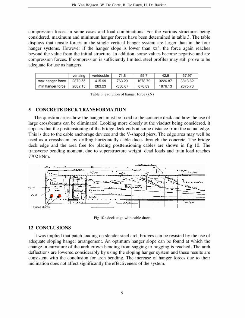
The question arises how the hangers must be fixed to the concrete deck and how the use of large crossbeams can be eliminated. Looking more closely at the viaduct being considered, it appears that the posttensioning of the bridge deck ends at some distance from the actual edge. This is due to the cable anchorage devices and the V-shaped piers. The edge area may well be used as a crossbeam, by drilling horizontally cable ducts through the concrete. The bridge deck edge and the area free for placing posttensioning cables are shown in fig 10. The transverse bending moment, due to superstructure weight, dead loads and train load reaches 7702 kNm.
Fig 10 : deck edge with cable ducts
12 CONCLUSIONS
It was implied that patch loading on slender steel arch bridges can be resisted by the use of adequate sloping hanger arrangement. An optimum hanger slope can be found at which the change in curvature of the arch crown bending from sagging to hogging is reached. The arch deflections are lowered considerably by using the sloping hanger system and these results are consistent with the conclusion for arch bending. The increase of hanger forces due to their inclination does not affect significantly the effectiveness of the system.
Cable ducts
Ph. Van Bogaert, W. De Corte, B. De Pauw, H. De Backer.
10
In the case of modernizing a multi-span concrete viaduct in urban environment, a steel arch suspension system may enable to suppress effectively the heavy piers below the viaduct. In the particular case being considered, crossbeams are unnecessary, due to the special bridge deck edge composition.
REFERENCES i Van Bogaert, Ph. and De Pauw, B. ‘Tied Arch Bridges with Radial Oriented Hangers, subjected to Rail Traffic’ Report IABSE Symposium ‘Structures for High-Speed Railway Transportation’. Ed Int. Assoc for Bridge and Struct. Engineering Antwerp 2003. pp 142-143 + 6pp CD-R
ii ENV 1993 (Eurocode 3-2) Design of steel structures – Part 2 : Steel Bridges. Sept 1997.
CEN-Brussels