Slag Foaming Smelting Reduction and Control Car ...
8
ISIJ International. Vol. 32 (1992). No. 1, pp. 87-94 Slag Foaming in Smelting bonaceous Materials Reduction and Its Control with Car- Yuji OGAWA. Hiroyuki KATAYAMA. Hiroshi HIRATA. Naoki TOKUMITSU and Masao YAMAUCH11 ) Steelmaking Process. Process Technology Laboratories. Technical DevelopmentBureau, Nippon Steel Corporation, Shintomi, Futtsu. Chiba-ken. 299-1 2 Japan. 1 ) Sakai Works, Nippon Stee] Corporation, Chikkou-Yawata, Sakai, Osaka-fu. 590 Jepan. (Received on June l7. 1991; accepted in final form on September 20. 1997) In the smelting reduction process of the thick slag layer type, it is important to keep slag height stably without abnormal slag foaming. This study investigated the mechanism of slag foaming control with car- bonaceous materials by experiments using a I -ton smelting reduction furnace and by X-ray fluoroscopic observation of phenomena occurring in a small graphite crucible. As the carbonaceous material was not wettable with slag, small bubbles coalesced on its surface. Becausethe large bubbles due to the coales- cence of small bubbles rise through the foaming slag layer at a relatively high speed, the foaming of slag may be restrained. It was found that the smaller the size of the carbonaceous material was, the more effective was the carbonaceous material in controlling the foaming of slag. A certain extent of relative motion between carbonaceous material and slag was necessary to promote the coalescence of small bubbles. It was experimentally confirmed that the smelting reduction in I OO-ton scale furnace can stably operate under the condition that the carbonaceous material is present in a sufficient amount in the slag. KEYWORDS: slag foaming; smelting reductionj suppression; carbonaceous materials; coke; coal: X-ray fluoroscopy; wettability; bubbles; coalescence. 1. Introduction A smelting reduction process reported recently is characterized by the shielding of stirred metal bath from the top-blown oxygen jet by a thick layer of slag.1) This smelting reduction process can promote the reduction reaction under a highly oxidizing post-combustion at- mosphere and suppress dust generation. The process was developed originally in the smelting reduction of chromium ore,2) and studies are now under way for its application to the smelting reduction of iron ore. In the smelting reduction process of the thick slag layer type, it is important to keep the slag height stable without abnormal slag foaming. It was previously found that the presence of carbonaceous materials in the slag layer was effective in controlling its abnormal slag foaming.3) However, the mechanism of slag foaming control with carbonaceous materials is still to be clarified in many res pects . Authors investigated the internal condition of slag foaming and the mechanism of carbonaceous materials acting on gas bubbles by experiments using a smelting reduction furnace, and by X-ray fluoroscopic observa- tions of phenomena occurring in a small crucible in this study. 2. One-ton Smelting Reduction Furnace Experiments 2.1. Experimental Procedure Theexperimental apparatus is schematically illustrated in Fig. 1. Theapparatus is a small-size, combined-blowing converter vessel that permits the adjustment of metal temperature by induction heating if necessary. Main experimental conditions are given in Table l. In the experiment, 600 kg of hot metal was charged into the converter, 150 to 200kg of slag was formed with lime and silica and the bath was smelting reduced while adding iron ore and carbonaceous material so as to maintain the bath temperature at approximately 1 500'C. During the smelting reduction, oxygen was top blown, and the bath was stirred by bottom blowing argon and oxygen. The slag ratio to metal adopted in the experiment is higher than in the commercial steelmaking converters. Table 2 Iists the size and chemical composition of Gas sampler 02-lance Dolomite , . . .. o o brick ~ Slag ~ o ' o ~ o Metal o I nduction coi I i:1 ~. MgO-C Ar brick Tuyere 02 Fig. l. Apparatus for 1-ton smelting reduction furnace ex- periments. 87 C 1992 ISIJ
Transcript of Slag Foaming Smelting Reduction and Control Car ...
ISIJ International. Vol. 32 (1992). No. 1, pp. 87-94
Slag Foaming in Smelting
bonaceousMaterials
Reduction and Its Control with Car-
Yuji OGAWA.Hiroyuki KATAYAMA.Hiroshi HIRATA.Naoki TOKUMITSUand MasaoYAMAUCH11)
Steelmaking Process. Process Technology Laboratories. Technical DevelopmentBureau, Nippon Steel Corporation, Shintomi,Futtsu. Chiba-ken. 299-1 2Japan. 1)Sakai Works, Nippon Stee] Corporation, Chikkou-Yawata, Sakai, Osaka-fu. 590Jepan.
(Received on June l7. 1991; accepted in final form on September20. 1997)
In the smelting reduction process of the thick slag layer type, it is important to keep slag height stablywithout abnormal slag foaming. This study investigated the mechanismof slag foaming control with car-bonaceousmaterials by experiments using a I -ton smelting reduction furnace and by X-ray fluoroscopicobservation of phenomenaoccurring in a small graphite crucible. As the carbonaceous material was notwettable with slag, small bubbles coalesced on its surface. Becausethe large bubbles due to the coales-
cence of small bubbles rise through the foaming slag layer at a relatively high speed, the foaming of slag
maybe restrained. It was found that the smaller the size of the carbonaceous material was, the moreeffective was the carbonaceous material in controlling the foaming of slag. A certain extent of relative
motion between carbonaceous material and slag was necessary to promote the coalescence of smallbubbles. It wasexperimentally confirmed that the smelting reduction in IOO-ton scale furnace can stablyoperate under the condition that the carbonaceous material is present in a sufficient amount in the slag.
KEYWORDS:slag foaming; smelting reductionj suppression; carbonaceous materials; coke; coal: X-rayfluoroscopy; wettability; bubbles; coalescence.
1. Introduction
A smelting reduction process reported recently is
characterized by the shielding of stirred metal bath fromthe top-blown oxygenjet by a thick layer of slag.1) Thissmelting reduction process can promote the reductionreaction under a highly oxidizing post-combustion at-
mosphereand suppress dust generation. The process
was developed originally in the smelting reduction ofchromiumore,2) and studies are nowunder way for its
application to the smelting reduction of iron ore.In the smelting reduction process of the thick slag layer
type, it is important to keep the slag height stable withoutabnormal slag foaming. It waspreviously found that the
presence of carbonaceousmaterials in the slag layer waseffective in controlling its abnormal slag foaming.3)
However, the mechanismof slag foaming control withcarbonaceous materials is still to be clarified in manyres pects
.
Authors investigated the internal condition of slag
foaming and the mechanismof carbonaceousmaterialsacting on gas bubbles by experiments using a smeltingreduction furnace, and by X-ray fluoroscopic observa-tions of phenomenaoccurring in a small crucible in this
study.
2. One-ton Smelting Reduction Furnace Experiments
2.1. Experimental Procedure
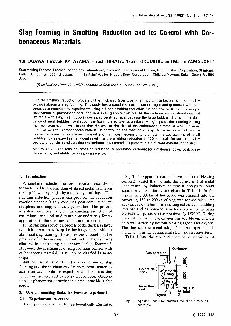
Theexperimental apparatus is schematically illustrated
in Fig. 1. Theapparatus is asmall-size, combined-blowingconverter vessel that permits the adjustment of metaltemperature by induction heating if necessary. Mainexperimental conditions are given in Table l. In theexperiment, 600kg of hot metal was charged into the
converter, 150 to 200kg of slag was formed with limeandsilica and the bath wassmelting reducedwhile addingiron ore and carbonaceous material so as to maintainthe bath temperature at approximately 1500'C. Duringthe smelting reduction, oxygen was top blown, and thebath was stirred by bottom blowing argon and oxygen.The slag ratio to metal adopted in the experiment is
higher than in the commercial steelmaking converters.Table 2 Iists the size and chemical composition of
Gassampler02-lance
Dolomite, . . .. oobrick ~ Slag ~
o'
o ~o Metal o
Inductioncoi I
i:1 ~. MgO-CAr brick
Tuyere 02
Fig. l. Apparatus for 1-ton smelting reduction furnace ex-periments.
87 C 1992 ISIJ

ISIJ International, Vol.
Table l. Conditions in l-ton smelting reduction experi-
ments.(a) Operating parameters
32 (1 992), No. 1
5
Ore feed rate
Cokefeed ratc
Topblowing 02Bottomblowing 02/ArTemperatureAmount'of metal
Amountof slag
(kg/min)(kg/min)(N//min)(N//min)('C)
(kg)
(kg)
25l-2
I300-1 800200/ IOO
l 50060(~700
l5(~250
O:i:*,0~4
,~_ 3E82~l
(b) Slag composition during experiment (mass"/.)
Al203 MgO
ore feed rateOUt (k9lmin)of '~~'l'ace
D\ A2L3 D5'O\xL\~;\;~doj~]~:;:~L~~\~\Q~A)~:\~:.~~~: o 3'1 A6'O
e34
T.Fe CaO Si02
O O.I 0.2 0.3 0.4 0.5 0.6
CokeISlag massratio
Fig. 2. Effectsofcoke/slagmass ratio on slagfoamingratio.
l-5 40-50 2040 5-20 5-20
Table 2. Size and chemical composition of raw materials.
(masso/o)
(a) Ore
TFe SIO Al203 CaOMgO P SizeSPellet ore 67.3 l.38 043 0,ll 0.97 0,007 O.003 lOl5mmFine ore 68.0 0.96 0.57 0.03 0.04 0.034 0.003 ~).25m
e4~ST3'~
,,02*~1C')
(b) Carbonaceousmaterial
F.C. Water SizeV.M. Ash
i2, I I. 5 1O25mm8,46 3,7 10-25 mm
Cokelsla9massratk)
/'0'10 A0'20o0'15 A0'25
e/o~4////;oAl//
LumpcokeLumpcoal
85.5 2,4
51, 1 36,8
raw materials used in the experiments. Iron ore wasusedmainly in the form of pellets, and fine ore was bottominjected in someof the experiments. Lumpcoke wasused
as carbonaceous material for the most part, and it wasconstantly fed to makeup for its consumption in thevessel. In someof the experiments, the carbonaceousmaterial wasnot added, and the behavior of slag foaming
was observed as the amountof carbonaceous materialdwindled in the vessel. In someother experiments, cokebreeze was injected through the top-blowing lance orthrough the bottom of the furnace, or used together withlump coke, or lump coal wasused in place of coke.
Thefoaming slag height wasdetermined by immersingan iron rod down to the bottom of the furnace, andmeasuring the slag deposition height on the iron rod after
its withdrawal from the bath. Assuming that all the
carbonaceous materials charged were entrapped in theslag layer, the gas volume in the slag layer wascalculated
by Eq. (1), and the experimental results were organizedby the slag foaming ratio defined by Eq. (2).
Vs+VG=(H-HM)x ITR2- Wc/pc """"-"'(1)
Vs= Wslps
HM=(WM/pM)/1TR2
Slag foammgratioVs+VG=I+
VG..........(2)
~ Vs Vs'where, H: measuredlevel of the top surface of
the slag (m)
HM[m]: calculated metal bath height (m)
88
O 1 2 3 4 5 6Ore feed rate (kg/min)
Fig. 3. Effects of iron ore feed rate on slag foaming ratio.
C 1992 ISIJ
R: inner radius of furnace (m)VG: gas volume in the slag layer (m3)Vs: slag volume (m3)
Wc: massof carbonaceousmaterial (kg)
WM: massof metal (kg)
Ws[kg]: massof slag (kg)
pc: apparent density ofcarbonaceous ma-terial (kg/m3)
pM: density of of metal (kg/m3)
ps: density of slag (kg/m3).
Themassof the carbonaceousmaterials, slag andmetal
were calculated from the feed rate of the iron ore andcarbonaceous material, and the changes in the com-position of the waste gas, slag and metal.
2.2. Experimental Results
Figure 2showsthe relationship of the coke/slag massratio in the furnace vs. slag foaming ratio with chang-ing iron ore feed rate. The slag foaming ratio increas-
ed with increasing iron ore feed rate and decreasing
amountof coke. Figure 2 is rearranged into Fig. 3asrelationship between the iron ore feed rate and the slag
foaming ratio at the samecoke/slag mass ratio. Theslag foaming ratio increased approximately in propor-tion to the iron ore feed rate.
In a steady state, gas volume in the slag layer is
expressed as follows:
VG=(QRT+QBTB)T1273..........,,..........(3)
where, QB: flow rate of bottom-blown gas (Nm3/sec)
QR: flow rate of COgas evolved by the reduc-tion of iron ore (Nm3/sec)
T: bath temperature

ISIJ lnternational, Vol.
T: average residence time of evolved COgasin slag layef (sec)
TB: average residence time ofbottom-blown gas(sec)
.
FromEqs. (2) and (3), the slag foaming ratio is givenby the following equation.
Slag foaming ratio = I+,(QRT+QBTB)T1273...(4)
Since QRis considered to be proportionate to the iron
ore feed rate, comparing Eq. (4) with Fig. 3, the effect
of the bottom-blown gas flow rate on the slag foamingratio is regarded as negligibly small., Therefore, the
average residence time of the evolved COgas, T, can becalculated by Eq. (4) without the term of QBTB.The flowrate of the evolved COgas wasdetermined from the iron
ore feed rate by assumingthat the iron oxide in the iron
ore was all Fe203. Figure 4 shows the relationship
between the average residence time of the COgas andthe coke/slag mass ratio for almost constant slag
composition. It is evident that the two variables arealmost uniquely related to each other, regardless of theiron ore feed rate.
Figure 5 shows the effect of the carbonaceousmaterial/slag mass ratio on the average residence timeof the reduction gas whenlump coke is singly used, ascomparedwith cases of its combineduse with top-blownor bottom-injected coke breeze, the case of coke breeze
2.5
2,0
~ooo' I .5
~'H I .O
0.5
^\~~:C~~^
Ore feed rate(kg/min)
2.0 5.03.5 6.04.0
CaOISiO,: 1.0
Al.O* : IO%MgO: 10%
~)~_~~[]
-,,o
O 0.1 O.2 0.3 0.4 0.5 O.6
Coke/slag massratio
Effect of coke/slag massratio on the estimated averageresidence time of CObubbles (~). '
32 (1992), No. 1
in single use, and the case of lump coal in single use. Asthe carbonaceousmaterial/slag massratio decreases, the
average residence time of the reduction gas and the slag
foaming ratio increase. Whenboth coke freeze and lumpcoke are used, the slag foaming level is lower than whenlump coke is singly used in the sameamount.
3. X-ray Fluoroscopic Observations of PhenomenainSmall Crucible
3.1. Experimental Procedure
The experimental apparatus is as schematized in Fig.6. Electrolytic iron and slag prepared as prescribed werecharged into a thin graphite crucible measuring 20mm(wide) x 66mm(10ng) x 120mm(deep) inside dimen-sions, melted using a silicon carbide resistance furnace,
and held at 1500'C. After adding iron ore pellets, the
phenomenaproduced in the foaming slag bath by theslag-metal reaction were observed by X-ray fluoroscopy(maximumX-ray tube voltage: 300kV). X-ray images
were recorded on the videotape recorder (VTR) andanalyzed to measurethe slag height andbubble diameter.The videotape wasplayed at a maximumspeed of 200frames/sec to observe fast moving bubbles. Water-granulated blast-furnace slag was dried and adjustedto the basicity (CaO/Si02 ratio) of unity with silicic
anhydride. To enhance the contrast of the slag andbubbles, lOmasso/~ barium oxide (B~O) was added tothe slag. Calcium oxide was replaced by the molarequivalent of BaOso as not to changethe chemical natureof the slag much. The chemical composition of theprepared slag is given in Table 3. The experiments wereconducted all in an argon atmospher~.
Besides the phenomenain the foaming slag layer, thebehavior of bubbles contacting the carbonaceous ma-terial block and the change in the bubbles and foamaround the carbonaceous material block was observed.Theblock wasattached to an alumina rod and immersedin the slag. Graphite, coke, and glassy carbon, which is
less likely to react with the iron oxide in the slag layer,
Fig. 4.
2.5
2.0
~ 1.5o(,,,,
~H 10
0.5
o
eLumpcoke0+Cokebreeze top bbwtlgJL+ cokeblleze in~cttr]
L e ACokebreezetopbbwil9ordy
I LumpcQal\ ~'~Lt.
1
CaO/SO2:10l~ 'UaOa:109',
M~:10 9',\;\:~,~~~~~C;~O
~\~.
~!Jt'~~;:~~L~e-'--leLe__
O 0.1 0.2 0.3 0.4 0.5 0.6Carbonaceousmaterial Isl8gmassratlo
Effects of carbonaceous material/slag mass ratio onaverage residence time of bubbles (T).
Monitor TVFurnace TVcamera
SlagMetal
Video tape recorder
X-ray tubeImageintensifier
Ar gas
Frg. 6. Experimental apparatus for X-rayservation with a small curcible.
Table 3. Chemical compositionfiuoroscopic observation
fluoroscopic ob-
of slag used(masso/o)
in X-ray
CaO BaO Si02 Al203 MgO MnO FeO SFig. 5. 33.8 l0.0 37,5 13, 1 3,7 - I 0.7
89 C 1992 ISIJ

ISIJ International, Vol. 32 (1992). No. 1
10mm
SIa9
o o oooo o
o
o e s~ oeQo*o~:o~~!Q oeoeO Qooe__9~(oooOo'oopo Q
eo, o o' oa o
Oo OO
e o'D 'lQ'L'ebeQe e$00oeal'a'eoe ~' OeQ'o 1' O%'.%Ot' eO~S'.OPeP
~" eet~;~~:;~!~~
be.a..,0:pd
e
OeOOOQeO"~ te o $'ae O. OoS'Qee
" eo"Oe'F'oo l' '~;"e J~d]
O~' -~; ' ee~r'0'O $' t l" ~':Q Oo
,L. d"": ; oft '~"t'eo
"~~':~""At~~~'e. .S'8''
r~':~~T';t":~'..'C~{_"'s"rt$"et:~11Lar9e bubbleS~'~:~:-"
. ..,:~?'
=
"'Ot':~:.'.:,8.~'~l"'~:""'
':i'
;~1;,..,~
3'e"' si.:~:•Y'^'a~!;;~s^;;
" '.":f:~ 'e'l5$~~~t',
FOam
Metal
(a)
Fig. 7.
(b) (C) (d)
X-ray fluoroscopic images of slag foaming after addition of iron ore pellets.
L'--I1Omm(a) l=0 (sec) (b) t=0.01 (c) t=0.02 (d) t=0.03
Fig. 8. X-ray fluoroscopic images ofbubbles around graphiteblock.
were used as carbonaceous materials. Iron ore pellets
and alumina blocks, both wettable by the slag, were usedfor comparison with the carbonaceousmaterials.
3.2. Results of Observations
Theprocess of slag foaming after the addition of iron
ore pellets is schematically illustrated with X-ray imagesin Fig. 7. As the pellets dissolved, the CObubbles formedat the slag-metal interface. At the early stage, the bubblesdid not makefoam but merely rose in the slag beingdispersed as shownin Fig. 7(a). TheCObubbles steeplydecreased in diameter, and a foam layer started to takeshapein the top of the slag bath whenthe bubble diameterfell below 2mm(Fig. 7(b)). After the coexistence of thedispersed gas layer and foam layer, the entire slag bathbecamefoamy (Fig. 7(c)). Large bubbles exceeding Icmin diameter then started to evolve from the slagmetalinterface as shownin Fig. 7(d). They were observed torise through the slag bath at a relatively high speed. Themechanismof large bubble generation witnessed in the
present experiments is not knownyet.
The behavior of a single CObubble measuring about6mmin diameter in contacting a graphite block is shownin Fig. 8. Whenthe CObubble contacted the graphite
C 1992 ISIJ 90
block, it was observed to instantaneously spread alongthe surface of the graphite block. TheCOgas gatheredand left the top of the block as a large bubble. Thebubblebehavior was almost the samewhena coke or glassycarbon block was used instead of the graphite block.However, whena bubble contacted an iron ore pellet, it
did not spread over the pellet surface but rose aroundthe pellet, as shownin Fig. 9.
Lastly, a glassy carbon block was immersed in afoaming slag beth, and the behavior of evolved CObubbles wasobserved. Whenthe glassy carbon block washeld still, no appreciable changewasobserved in the CObubbles around the block. However,whenthe block wasmovedup and down, a large bubble formation wasobserved, as shown in Fig. 10. The large bubble is
considered to have resulted from the coalescence of smallbubbles on the glassy carbon block surface. In the caseof a graphite or coke block, it reacted with iron oxidein slag and large CObubbles were evolved before theblock wasmoved. Therefore, a large bubble caused bycoalescence of small bubbles around the block wasnotdistinguished from the evolved CObubbles. Whenanalumina biock wasimmersedin place of the glassy carbonblock and was movedup and down, no large bubbleformation wasobserved.
4. Smelting Reduction Experiments with 100-ton Con-verter
4.1. Experimental Procedure
A 180-ton LDconverter wasmodified into a 100-tonsmelting reduction furnace and was used to investigatethe conditions of slag foaming control in a large furnace.The experimental apparatus is schematically shown inFig. 11. About 100 tons of hot metal wascharged intothe furnace, and slag was formed by oxygen blowing.The hot metal was adjusted to a temperature of aboutl 500'C and was smelting-reduced with the addition ofiron ore. Table 4 Iists the chemical compositions andsizes of the raw materials. Under standard conditions,the iron ore, carbonaceousmaterial, and burnt lime werecontinuously top charged into the furnace. The iron orecharge rate was adjusted to keep the metal bathtemperature within ~30'C of the specified level. Coke

ISIJ lnternational, Vol. 32 (1992), No, 1
(a) t=O(sec) (b) I=0.02 (c) t=0.04(d) t=0.06 (e) t=0.08 (D t=O. lO
Fig. 9.
X-ray fiuoroscopic images of single bubble in
contact with iron ore pellet.
iOmm
Alumina rod
Glassy carb6n
Table 4.
(a) Ore
Size and chemical composition of raw materials
and fluxes used in 100-ton smelting reductionexperiment. (masso/o)
T.Fe Si02 Al203 CaO MgO P Size
Foam66.8 3,00 O.51 0.05 0.0 1 o,05 2-20 mm
(b) Coke
F.C. Ash Size
1Omm BubbleL_J10. X-ray fluoroscopic image of large bubble formed in
foaming slag bath by glassy carbon block.
84.2 l I.O 5-50 mmFig. (c) Flux (Dolomite)
CaO MgO Si02 C02 Size
Lumpcoke
Fig.
02Lump
iron ore
l\-'sta9
Metal
61.7 32.8 0,09 4.8 1 530mm
Table 5. Conditions of 100-ton smelting reduction experi-
ment.
c02
ll. Schematic of 100 ton smelting reductron furnace
was added according to the carbon balance calculatedfrom the waste gas analysis, so that the residual car-bonaceous material level was kept virtually constantin the furnace.
Main experimental conditions are listed in Table 5.
Carbondioxide (C02) wasused as bottom blowing gas.4)
Theslag volume, amountof carbonaceousmaterial, iron
ore feed rate and top-blown oxygenflow rate werevariedto investigate their effects on slag foaming.
4.2. Experimental Results
Table 6showsthe effects of the amountsof slag andcoke in slag on the stability of slag foaming. In experimentNo. l, the slag and coke amountswere set at '15 and 5tons, respectively. Afew minutes after the start of oxygen
Bath surface area (m2)
Amountof slag (t)
Amountof metal (t)
Topblowing 02 (Nm3/h)Bottom blowing C02 (Nm3/h)Amountofcokeinslag (t)
Lance nozzle type
3015~58C~120
20OO0-30OOO
l 800
5~752mmip(Center) +70mmcx 6
Table 6. Effects of the amountsof slag andcoke on stability
of slag foaming in 100-ton furnace.
Top blowingNo. 02
(Nm3/h)
Ore feed
rate(t/h)
Amountof slag
(t)
Amountofcoke in
slag (t)
Stability
offoaming
1
23456
20ooo
20ooo20ooo20ooo20ooo30ooo
21
21
36384465
15
3036304530
5
18
2233
4732
Abnormalfoaming
UnstableUnstableStable
Stable
Stable
91 C 1992 ISIJ

[SIJ International. Vol,
blowing, the slag overflowed the furnace and madeit
impossible to continue the oxygen blow. Whenthe slag
and coke amountswere increased (experiments Nos. 2and 3), abnormal slag foaming did not occur, but theslag occasionally overflowed the furnace. The furnace
was found to stably operate whenthe slag weight andcoke weight are approximately equal. It was also
confirmed that the furnace can stably operate evenwhenthe COgas evolution rate is increased by increasingthe iron ore feed rate as in experiments Nos. 5and 6.
The iron ore feed rate was increased by increasing the
post-combustion rate and raising the bath temperaturein No. 5, and by increasing the oxygen flow rate in No.6. After these experiments, the critical amount ofcarbonaceous materials with which the furnace stably
operate could be lowered to approximately 20 o/o of theslag amount by decreasing the size of carbonaceousmaterials.
Whenthe slag height wasmeasuredby the short circuit
method, it wasfound that the volume ratio of slag, gas,and carbonaceousmaterial in the foaming slag were 20,
50 and 30 o/o, respectively.5) This meansthat slopping is
llkely to occur whenthe slag foaming ratio exceeds 3in
this furnace.
Slag foaming wasalso confirmed to occur even in the
presence of a sufficient amountof carbonaceousmaterial
whenthe slag composition considerably deviated fromnormality.
Fromthe above-mentioned results, it is concluded thatthe presence of a sufficient amount of carbonaceousmaterial in slag of optimumcomposition is prerequisite
to the successful regulation of slag foaming. It wasconfirmed that this condition enables the furnace tostably operate even in large-scale smelting reductionexperiments.
5. Discussion
5.1. Mechanismof Slag FoamingControl with Carbo-naceous Materials
As evident from the X-ray fiuoroscopic observation,small bubbles 2mmor moreandsomelarge bubbles Icmor morein diameter are both present in the foaming slag
bath in smelting reduction. The small bubbles form afoam layer and rupture at the top surface of the foamingslag in order, while the large bubbles rise through the
foam layer at a relatively high speed. As the proportionof small bubbles decreases and that of large bubblesincreases in the slag bath, the average residence time ofthe bubbles in the slag bath decreases, and the slag
foaming ratio consequently falls.
In l-ton furnace experiment, the estimated averageresidence time of CObubbles decreased with increasingthe amountof carbonaceous material in the slag bath,
as shown in Fig. 4. This is probably because car-bonaceousmaterials promote the coalescence of smallbubbles in foamand the proportion of large bubbies in-
creases as the amountof carbonaceousmaterial increases.
Whenthe amount of carbonaceous material exceeds
a certain limit, the foam layer maynot be formed, andinstead a dispersed bubble layer is formed as shownin
C 1992 ISIJ 92
32 (1992), No. 1
Fig. 7(a).
According to the observation of bubble and foambehavior by X-ray fiuoroscopy, the coalescence of smallbubbles is considered to be accelerated due to un-wettability between carbonaceous material and slag bythe following reason: (1) carbonaceous material is notwettable with slag, (2) iron ore and alumina are easily
wettable with slag, and (3) COgas evolution by reactionbetween glassy carbon and iron oxide in the slag wasscarcely recognized.
Whenthe carbonaceousmaterial block wasnot moved,no appreciable changewasobserved in the foamaroundthe block. This finding suggests that a certain extent ofrelative motion betweencarbonaceousmaterial andsmallbubbles is necessary to promote the coalescence of thebubbles. In the 1-ton experiments, fine coke was moreeffective than lump coke in controlling the foaming ofthe slag bath, as shownin Fig. 5. It can thus said thatthe foaming ratio decreases with increasing area andfrequency of contact between the carbonaceousmaterialand small bubbles. Lumpcoal wasalso highly effective
in controlling the slag foaming, probably because it wasrapidly heated to decrepitate and the area and frequencyof contact with small bubbles increased consequently.6)
Whencoke breeze was top blown, it proved rather lowin its effect of controlling the foaming of the slag, perhapsbecause it was too sparsely scattered to be effectively
introduced into the slag bath.
Another possible mechanismof slag foaming controlwith carbonaceous materials is a reduction in the ironoxide and P205 concentrations, that are likely re-sponsible for the slag foaming. Figure 12 shows the ef-
fect of the coke/slag mass ratio on the total iron andP205 contents of slag in I ton-scale experiments. Nocorrelation was recognized between the coke amountinthe furnace and the total iron and P205contents of slagin these experiments.
From the above discussion, it is concluded that theslag foaming can be controlied by the coalescence ofsmall bubbles on the carbonaceousmaterial surface be-
cause thc carbonaceous material is not easily wettablewith slag.
OQ~~i~~'
LhH
a~
Cokelslag massratio
Fig. 12. Effect of coke/slag mass ratio on total iron andphosphate content of slag in l-ton furnace,
0.4ceo.3
0.2
o.1
eo e.ol'eel
eec,L
eed' $)t'
,,.
eo5 e
e4 d'
3.
::,1' :8~
2 e• eee ',
1oo 0.1 0.2 0.3 0.4 0.5 0.6
Coke/sl massr '

ISIJ International. Vol.
5.2. Advantageof Smelting Reduction Process with MassUseof CarbonaceousMaterial
Thesmelting reduction process that utilize a thlck slag
layer is characterized by improved post-combustionefficiency and reduced dust emission.1) As describedabove, the presence of carbonaceousmaterial wasfoundto be indispensable for controlling the foaming of siagin thls process. The required amountof carbonaceousmaterial accounts for as muchas 20 o/o of the slag mass.
Thecarbonaceousmaterial in the furnace has its partin the reductlon of iron oxide, recarburization of metaland heat transfer to the metal bath, aside from the
suppression of slag foaming. It is reported that aboutone-third of the overall reductlon occurs on the
carbonaceousmaterial surface in large smelting reductionfurnaces. 1) Underthe operating conditions characterized
by high heat efficiency and low waste gas temperature,heat radiation and gas convectlon account for a mere20 to 300/0 of the overall heat transfer, and the rest
is considered to be accommodatedby the circulating
carbonaceousmaterial.7) Thepresence of a large amountof carbonaceous material in the slag layer is necessaryalso from the viewpoint of operating the smeltingreduction furnace efficiently. Lump carbonaceousmaterial is preferred to its fine version because the latter
is sparsely scattered whencharged into the furnace.
5.3. General Discussion of Slag FoamingControl
It has been known that injection of carbonaceousmaterial into foaming slag can lower the slag height.
Iso et al.8) reported that in LDconverter steelmaking
process, injection of coke breeze for I to 2min into
foaming slag can prevent the slopping of slag out of the
furnace. With regards the hot metal dephosphorization
process, a report introduces the technique of loweringthe slag height by top blowing coke breeze into the slag
layer. 9) Theamountof carbonaceousmaterial to suppressthe slag foaming in the above processes is smaller thanthat in the smelting reduction process.
In the electric arc furnace process, both the iron oxideconcentration in slag and carbon content in metal arenot so high. Therefore, coke breeze andoxygenare blowntogether conversely to increase the gas evolution rate andthen to promote slag foaming, in order to raise energyefficiency and improve equipment durability. Io)
In the smelting reduction process, the presence of anecessary amountof carbonaceous material in the slag
layer is an essential condition for controlling the foamingof slag and operating the furnace efficiency.
As mentioned above, the respective processes differ in
the modeof use of carbonaceous material for slag
foaming control. The difference maybe explained on aunified basis in the way: Whenslag begins overflowingfrom the top of the furnace, the slag foaming ratio
depends on the furnace volume and the slag amount.This critical slag foaming ratio in specific reactors (V*) is
determined by the still slag bath volume and the gasvolume above the top surface of the slag in the reactor(VG,~**) as follows.
V* = I+ V /V ..........(5)G,~** s ""'
93
32 (1992), No. 1
- Io'~"s_
8o
EAF onp LD
v'
SR
103
O 1 2 34 5 6 7QcolV'
Fig. 13. Relationship between total gas evolution rate (Qco)and the critical slag foaming ratio (V*).
The slag foaming height dependson the gas evolution
rate (Qco)' If the gas escape rate from slag that depends
on the physical properties of slag is equal, the slag
slopping from the furnace mayoccur easily as the critical
foaming ratio V* is small and as the total gas evolution
rate (Qco) Is large. Therefore, the Qco/V* ratio can be
an index of the likelihood of slag slopping of a process.Figure 13 schematically shows the relationship betweenthe total gas evolution rate Qcoand the critical foamingratio V* for the 300-ton LD converter steelmaking
process (LD), 180-ton electric arc furnace steelmaking
process (EAF), hot metal dephosphorlzation process with
a 300-ton torpedo car (ORP),.and 100-ton smeltingreduction process in Sakai Works(SR). Thegasevolutionrate in the LDconverter steelmaking process is quitelarger than that in the smelting reduction process, butslag foaming can be controlled with a smaller amountcarbonaceous materiallo) because the critical foamingratio is reasonably larger. The Qco/V* ratio in the
torpedo car hot metal dephosphorization process is also
smaller than that in the smelting reduction process. This
meansthat slag slopping in SRoccurs easilier than thatin ORP. Therefore, more amount of carbonaceousmaterials maybe required for slag foaming control in
SRthan in ORP.In the electric arc furnace steelmaking
process, the total gas evolution rate is low, and the critical
slag foaming ratio is high. This means that the gasevolution rate must be increased by carbonaceousmaterial and oxygen blowing in order to cause slag
forming.
Of all the steelmaking and refining processes, the
smelting reduction process is most critically required to
promote the escape of gas from slag. The process is
characterized by the constant presence of carbonaceousmaterial in the s]ag layer as a necessary condition.
6. Summary
In the smelting reduction process that is characterizedby a liberal use of slag, the mechanismof slag foamingcontrol with carbonaceousmaterials was investigated byexperiments using a l-ton smelting reduction furnace and
@1992 ISIJ

ISIJ International, Vol. 32 (1992), No. 1
X-ray fluoroscopic observation using a small crucible.
Also, stable operating coditions were confirmed bylOO-ton furnace experiments. The experimental results
maybe summarizedas follows:(1) In the l-ton furnace experiments, the average
residence time of CObubbles was used as index of slag
foaming. It was found that the average residence timeof CObubbles uniquely depends on the carbonaceousmaterial/slag massratio, irrespective of gas volume, andincreases with decreasing amount of carbonaceousmaterial in the furnace.
(2) In the X-ray fluoroscopic observation experiment,small and large CObubbles, produced by the iron oxidereduction reactions, were both present in a foaming slag
bath, and the large bubbles rose through the foam layer
at a relatively high speed. Thecarbonaceousmaterial is
considered to restrain slag foaming by pr.omoting thecoalescence of small bubbles on its surface andencouragethe bubbles to escape through the top of the slag bath.
(3) Thecoalescence ofsmall bubbles is promotedbythe carbonaceous material, essentially because the car-bonaceous material is not readily wettable with slag
and the COgas is likely to spread along its surface.(4) The slag foaming height decreased with decreas-
ing carbonaceous material size. A certain extent ofrelative motion betweencarbonaceousmaterial and slag
was necessary to promote the coalescence of smallbubbles. Thesefindings meanthat the slag foaming height
can be effectively lowered by increasing the area and the
frequency of contact betweenthe carbonaceousmaterial
and small bubbles.(5) The' 100-ton smelting reduction furnace experi-
ments confirmed that the presence of a certain amountof carbonaceous material in the slag layer is necessaryfor the stable operation of the smelting reduction furnace.
(6) A Iarge amount of carbonaceous material is
required in the slag layer for efficient smelting reductionin terms of reduction, recarburization, and heat transfer.
Addition of lumpycarbonaceousmaterial is preferred to
that of fine carbonaceous, because the latter is sparselyscattered whenadded into the furnace.
(7) Theamountof carbonaceous materials requiredfor slag foaming control depends on the likelihood ofslag slopping in specific reactors. The likelihood of slag
slopping can be distinguished by the critical slag foamingratio and gas evolution rate in the furnace. Thesmeltingreduction process is essentially required to promote therelease of gas from slag, which calls for the constantpresence of carbonaceousmaterial in the slag layer.
Acknowledgment
The authors would like to thank the Committee onInterfacial Transport Phenomena(chaired by ProfessorMasanori Tokudaof TohokuUniversity) in the JointSociety of lron and Steel Basic Researchof the Institute
of lron and Steel of Japan, for discussion on the slag
foaming phenomenonand mechanismof slag foamingcontrol with carbonace6usmaterials.
l)
2)
3)
4)
5)
6)
7)
8)
9)
lO)
REFERENCESM. Matsuo, C. Saito. H. Katayama, H, Hirata, M. Kanemotoand T. Ibaraki: Tetsu-to-Hagan~, 74 (1988), 1871.
M. Fujita, H. Katayama, M. Kuwabara. C. Saito and H.Ishikawa: Tetsu-to-Hagani, 74 (1988), 680.
M. Matsuo, M, Sato, C. Saito, H. Hirata, H. Ishikawa and Y,Takamoto: CAMP-ISIJ,4(1991), 36.
H. Iso, Y. Jyono. K. Arima, M. Kanemoto,M. Okajima and H.Narita: Trans. Iron Stee/ Inst. Jpn., 28 (1988), 49.
M. Yamauchi, T. Ibaraki, M. Kanemoto,M. Matsuo. H. Hirataand T. Ohno: CAMP-ISIJ, 3(1990), 1075.
H. Katayama.M. Kuwabara,K. Kobayashi, T. Ohno,T. Ibarakiand M. Kanemoto:CAMP-ISIJ, 4(1991), 36.
H. Katayama,T. Ohno,M.Yamauchi,M. Matsuo, T. Kawamura
and T. Ibaraki: ISIJ Inl., 32 (1992),
H. Iso. K. Arima, M. Kanemoto, Y. Uedaand H. Yamane:Trans. Iron Stee[ Inst. Jpn.. 28 (1988), 382.S. Tsuruoka, K. Kiuchi. S. Yamamoto,J. Kinoshita, E. Aida, J.
Nakajima and H. Furuta: CAMP-ISIJ,4(1991), 48.
For example, D. Capodilupo. P. Macci, G. Brascugli, V. De.Angels: Proc, of the 6th Int. Iron and Steel Cong. Vol. 4, ISIJ,
Tokyo, (1990), 98.
@1992 ISIJ 94