SKYEMODULE M7 DATASHEET - JADAK · SKYEMODULE M7 DATASHEET ... This document covers the operating...
50
SKYEMODULE M7 DATASHEET VERSION 041814
Transcript of SKYEMODULE M7 DATASHEET - JADAK · SKYEMODULE M7 DATASHEET ... This document covers the operating...
SKYEMODULE M7 DATASHEET
VERSION 041814

S k y e M o d u l e M 7 D a t a s h e e t | 2
Skyetek Inc
1732 Wazee St. Ste 202 Denver, CO 80202 www.skyetek.com Main 720.328.3425 Fax:720.228.2400
COPYRIGHT INFORMATION: Copyright 2014 SkyeTek, Inc., 1732 Wazee St. Suite 202, Denver, Colorado 80202, U.S.A. All rights reserved.
Version 041814
This product or document is protected by copyright and distributed under licenses restricting its use, copying, distribution, and decompilation. No part of this product or document may be reproduced in any form by any means without prior written authorizat ion of SkyeTek and its licensors, if
any.
SkyeTek, and SkyeWare are trademarks or registered trademarks of SkyeTek, Inc.
MicroSoft and Windows are registered trademarks of Microsoft Corporation.
TECHNICAL SUPPORT AND CONTACT INFORMATION
SkyeTek, Inc.
1732 Wazee Street, Suite 202
Denver, CO 80202
http://www.skyetek.com
SALES:
TECHNICAL SUPPORT:

S k y e M o d u l e M 7 D a t a s h e e t | 3
Skyetek Inc
1732 Wazee St. Ste 202 Denver, CO 80202 www.skyetek.com Main 720.328.3425 Fax:720.228.2400
TABLE OF CONTENTS 1 About this Document ........................................................................................................ 9
1.1 Revision History ........................................................................................................ 9
2 Definition of Terms ........................................................................................................ 10
3 Ordering Information ...................................................................................................... 11
4 SkyeModule M7 Overview ................................................................................................. 12
4.1 Features ............................................................................................................... 12
4.2 Applications ........................................................................................................... 12
4.3 SkyeWareTM Software ............................................................................................... 13
5 Mechanical Specifications ................................................................................................ 14
6 Pinning Information ........................................................................................................ 16
6.1 Pin Mapping for the SkyeModule M7 ............................................................................. 16
6.2 Using the GPIO Pins ................................................................................................. 17
6.3 Using the 8-Through-Hole I/O Option............................................................................ 18
7 Environmental Specifications ............................................................................................ 19
7.1 Electrostatic Precautions .......................................................................................... 19
7.2 General Ratings and Operating Conditions ..................................................................... 19
8 Electrical Specifications .................................................................................................. 20
8.1 Absolute Maximum Range .......................................................................................... 21
9 Host Interface Specifications ............................................................................................ 22
9.1 Host to Reader Interfaces .......................................................................................... 22
9.2 TTL Serial ............................................................................................................. 23
9.3 USB 2.0 ................................................................................................................ 25
9.3.1 Bypassing the Host Interface Board ........................................................................... 25
10 Radio Specifications and Regional Compliance ....................................................................... 26
10.1 RF Radio Power ...................................................................................................... 26
S k y e M o d u l e M 7 D a t a s h e e t | 4
Skyetek Inc
1732 Wazee St. Ste 202 Denver, CO 80202 www.skyetek.com Main 720.328.3425 Fax:720.228.2400
10.2 Frequency Range .................................................................................................... 26
10.3 Tag Protocols ......................................................................................................... 26
10.4 Recommended Radio Settings for Regional Compliance ..................................................... 27
10.5 Adjusting System Parameters ..................................................................................... 27
10.6 Radio Test Models ................................................................................................... 27
10.7 Regional Regulations ................................................................................................ 28
10.8 Radio Specifications ................................................................................................. 29
11 Antenna Options ............................................................................................................ 30
12 Communication Specifications ........................................................................................... 31
12.1 Host Communication – SkyeTek Protocol v3 .................................................................... 31
12.2 Software Developer Tools .......................................................................................... 32
13 Customizing System Parameters ........................................................................................ 33
13.1 Changing System Parameters ..................................................................................... 33
13.2 Understanding System Parameter Formats ..................................................................... 35
13.2.1 Read System Parameter Command Format .............................................................. 35
13.2.2 Write System Parameter Format ........................................................................... 37
13.3 System Parameter Descriptions ................................................................................... 39
13.3.1 Serial Number .................................................................................................. 39
13.3.2 Firmware Version ............................................................................................. 39
13.3.3 Hardware Version ............................................................................................. 39
13.3.4 Product Code .................................................................................................. 40
13.3.5 Reader ID ....................................................................................................... 40
13.3.6 Reader Name .................................................................................................. 40
13.3.7 Host Interface Type .......................................................................................... 41
13.3.8 Host Interface Baud Rate .................................................................................... 41
13.3.9 User Port Direction ........................................................................................... 42
13.3.10 User Port Value ................................................................................................ 42

S k y e M o d u l e M 7 D a t a s h e e t | 5
Skyetek Inc
1732 Wazee St. Ste 202 Denver, CO 80202 www.skyetek.com Main 720.328.3425 Fax:720.228.2400
13.3.11 MUX Control .................................................................................................... 43
13.3.12 Operating Mode ............................................................................................... 43
13.3.13 Command Retry ............................................................................................... 43
13.3.14 Power Level .................................................................................................... 43
13.3.15 Current Frequency ............................................................................................ 45
13.3.16 Start Frequency ............................................................................................... 45
13.3.17 Stop Frequency ................................................................................................ 46
13.3.18 Hop Channel Spacing ......................................................................................... 47
13.3.19 Frequency Hopping Sequence .............................................................................. 47
13.3.20 Modulation Depth ............................................................................................. 48
13.3.21 Regulatory Mode .............................................................................................. 49
13.3.22 LBT Antenna Gain ............................................................................................. 50
S k y e M o d u l e M 7 D a t a s h e e t | 6
Skyetek Inc
1732 Wazee St. Ste 202 Denver, CO 80202 www.skyetek.com Main 720.328.3425 Fax:720.228.2400
LIST OF FIGURES Figure 4-1 SkyeModule M7 ................................................................................................ 12
Figure 5-1 SkyeModule M7 Dimensions .................................................................................... 15
Figure 6-1 M7 Connector Pin-outs ....................................................................................... 16
Figure 9-1 TTL Connection Diagram ....................................................................................... 23
Figure 9-2 TTL Interface .................................................................................................. 23
Figure 9-3 Circuit to Bypass Host Interface Board for USB Support ............................................... 25
S k y e M o d u l e M 7 D a t a s h e e t | 7
Skyetek Inc
1732 Wazee St. Ste 202 Denver, CO 80202 www.skyetek.com Main 720.328.3425 Fax:720.228.2400
LIST OF TABLES Table 1-1 Revision History .................................................................................................... 9
Table 3-1 SkyeTek Part Number Scheme ................................................................................ 11
Table 3-2 Part Number Details ............................................................................................ 11
Table 3-3 M7 Part Numbers ................................................................................................ 11
Table 6-1 SkyeModule M7 Connector Specifications .................................................................... 16
Table 6-2 SkyeModule M7 Pinout ........................................................................................... 17
Table 6-3 SkyeModule M7 J3 Connector Pin Mapping .................................................................. 18
Table 7-1 Environmental Ratings/Operating Conditions .............................................................. 19
Table 8-1 SkyeModule M7 Electrical Specifications ..................................................................... 20
Table 8-2 Absolute Maximum Ratings/Operating Conditions ......................................................... 21
Table 10-1 Recommended Reader Settings for Regional Compliances ........................................... 27
Table 10-2 SkyeModule M7 Agency Compliance ....................................................................... 28
Table 12-1 Request Format (bytes), ASCII Mode ...................................................................... 31
Table 12-2 Request format (bytes), Binary Mode ..................................................................... 31
Table 12-3 Response Format (bytes), ASCII Mode ..................................................................... 32
Table 12-4 Response Format (bytes), Binary Mode ................................................................... 32
Table 13-1 System Parameter Addresses, Lengths, and Default Values .......................................... 33
Table 13-2 Read System Parameter Command, ASCII Mode Request ............................................. 35
Table 13-3 Read System Parameter Command, ASCII Mode Response ............................................ 36
Table 13-4 Read System Parameter Command, Binary Mode Request ............................................ 36
Table 13-5 Read System Parameter Command, Binary Mode Response .......................................... 36
Table 13-6 Write System Parameter Command, ASCII Mode Request ............................................. 37
Table 13-7 Write System Parameter Command, ASCII Mode Response ........................................... 37
Table 13-8 Write System Parameter Command, Binary Mode Request ........................................... 38
Table 13-9 Write System Parameter Command, Binary Mode Response ......................................... 38
S k y e M o d u l e M 7 D a t a s h e e t | 8
Skyetek Inc
1732 Wazee St. Ste 202 Denver, CO 80202 www.skyetek.com Main 720.328.3425 Fax:720.228.2400
Table 13-10 Common Power Values ....................................................................................... 44
Table 13-11 Commonly Used Frequencies ............................................................................... 46
Table 13-12 Common Modulation Depth Values ........................................................................ 48
Table 13-13 Regulatory Mode Values ..................................................................................... 49
Table 13-14 Examples of LBT Antenna Gain Adjustment Values .................................................... 50
S k y e M o d u l e M 7 D a t a s h e e t | 9
Skyetek Inc
1732 Wazee St. Ste 202 Denver, CO 80202 www.skyetek.com Main 720.328.3425 Fax:720.228.2400
1 About this Document
This document covers the operating characteristics and modes of the SkyeModule M7. Included in this
document are electrical connection diagrams, timing characteristics, electrical and mechanical
specifications, system parameters, ordering information, and pin diagrams.
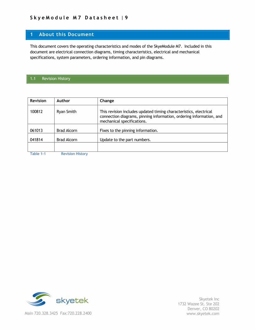
1.1 Revision History
Revision Author Change
100812 Ryan Smith This revision includes updated timing characteristics, electrical connection diagrams, pinning information, ordering information, and mechanical specifications.
061013 Brad Alcorn Fixes to the pinning information.
041814 Brad Alcorn Update to the part numbers.
Table 1-1 Revision History
S k y e M o d u l e M 7 D a t a s h e e t | 10
Skyetek Inc
1732 Wazee St. Ste 202 Denver, CO 80202 www.skyetek.com Main 720.328.3425 Fax:720.228.2400
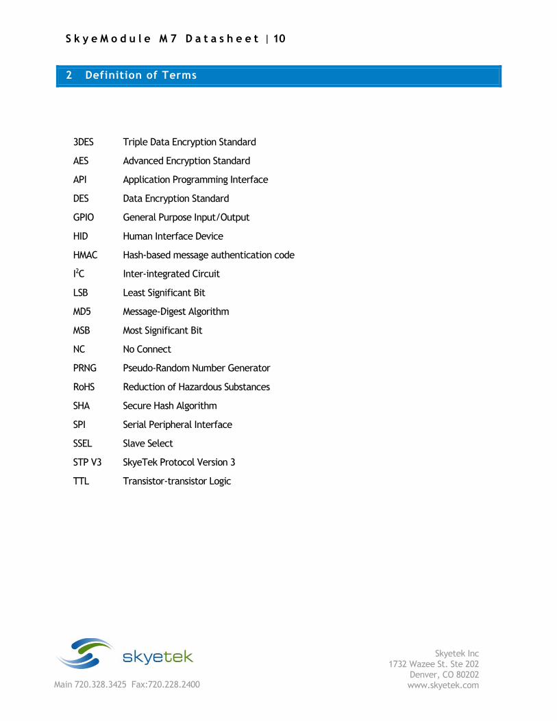
2 Definition of Terms
3DES Triple Data Encryption Standard
AES Advanced Encryption Standard
API Application Programming Interface
DES Data Encryption Standard
GPIO General Purpose Input/Output
HID Human Interface Device
HMAC Hash-based message authentication code
I2C Inter-integrated Circuit
LSB Least Significant Bit
MD5 Message-Digest Algorithm
MSB Most Significant Bit
NC No Connect
PRNG Pseudo-Random Number Generator
RoHS Reduction of Hazardous Substances
SHA Secure Hash Algorithm
SPI Serial Peripheral Interface
SSEL Slave Select
STP V3 SkyeTek Protocol Version 3
TTL Transistor-transistor Logic

S k y e M o d u l e M 7 D a t a s h e e t | 11
Skyetek Inc
1732 Wazee St. Ste 202 Denver, CO 80202 www.skyetek.com Main 720.328.3425 Fax:720.228.2400
3 Ordering Information
The M2 part number is constructed according to the SkyeTek part number specification below:
PF-PT-BT-OPTSProduct Fam
ily
Product Type
Build Type
Options
Table 3-1 SkyeTek Part Number Scheme
Details:
Code Options Description
Product
Family
SM = SkyeModule Highest level product family code.
Product Type M7 = M7 Specifies the specific part type.
Build Type MH = Mounting holes Specifies standard form factors or custom builds.
Options Blank = Serial, 38400B This field is left for special customer part numbers or
standard variations such I2C for I2C as the default host
interface. Consult the SkyeTek sales team for custom
orders.
NOTE: In developer kits, the module comes
programmed to USB.
Table 3-2 Part Number Details
As of the date of this document, the most current part numbers for the M7 are shown in Table 3-3
M7 Part Numbers. Always contact a reseller or the SkyeTek sales team for the latest part number.
Module Part Number
SkyeModule M7 SM-M7-MH
Table 3-3 M7 Part Numbers

S k y e M o d u l e M 7 D a t a s h e e t | 12
Skyetek Inc
1732 Wazee St. Ste 202 Denver, CO 80202 www.skyetek.com Main 720.328.3425 Fax:720.228.2400
4 SkyeModule M7 Overview
The SkyeModule M7 is the world’s smallest and most cost-effective UHF (862-955 MHz) RFID reader platform.
It can read and write to transponders based on the ISO 18000-6C (EPC C1G2/Gen2) air interface and
communications standards. The RF output power of the SkyeModule M7 is software-adjustable
from 9-24 dBm (8-250 mW) in 3 dB increments.
Figure 4-1 SkyeModule M7
4.1 Features
Designed for item-level tagging, consumables, handhelds, and label printers, the SkyeModule M7 offers the
following features:
Common communications protocol—All SkyeTek products use SkyeTek Protocol v3 (STPv3) to drive
low level communications. SkyeTek APIs built on top of STPv3 give you methods for exercising
readers and reading tags from your custom software applications.
The SkyeModule M7 is optimized to support a communication rate of 40 kbps. A standard 50 Ω
antenna output enables use of an external antenna to optimize the read range/rate.
The SkyeModule M7 has TTL (UART) serial and USB host-interface options. These options
are software-selectable to support both loosely and tightly coupled integrations. The
SkyeModule M7 has four programmable GPIO pins for I/O connections to peripherals.
Serial data rates are adjustable from 9.6 to 115.2 kbps. Field-upgradable firmware
provides forward compatibility for adding future tag protocols, security features, and
customized enhancements.
4.2 Applications
The SkyeModule M7 is a small and inexpensive RFID reader module with support for a wide variety of tags and
regions. The small size and wide feature set of the M7 lends itself well to the following types of applications:
RFID Handhelds
S k y e M o d u l e M 7 D a t a s h e e t | 13
Skyetek Inc
1732 Wazee St. Ste 202 Denver, CO 80202 www.skyetek.com Main 720.328.3425 Fax:720.228.2400
Machine Safety
Integrated RFID Readers
Label and Airline Tag Printers
4.3 SkyeWareTM Software
All SkyeModule M7 developer kits ship with the SkyeWare 4 software package for Microsoft®
Windows® to aid your RFID development process. This package includes:
Setup Wizard - This Wizard guides you through the setup, configuration, and testing of your
new SkyeModule reader. It takes you through all the steps necessary for connecting your
hardware, running diagnostic tests, and optimizing your reader configuration. It concludes
with useful links to additional SkyeTek software and documentation.
Demonstration functions – This utility offers a quick way to perform high-level demonstrations
of the basic functionality of the SkyeModule M7. You can test read range, anti-collision
(singulation) capabilities, and use inventory selection and memory functions.
Configuration – You can easily view and change reader configuration parameters or perform
basic tag operations, such as reading or writing to specified memory blocks on a tag.
Test Software – The test utility provides a GUI interface for constructing the SkyeTek
Protocol v3 commands in either ASCII or binary format, based on tag type and selected flags.
You can build and test low-level SkyeTek protocol commands and use all the features of the
reader at the protocol level. It is an excellent way to learn more about SkyeTek Protocol
v3 commands. For more information, see the SkyeTek Developer Kit User Guide.
APIs – SkyeTek offers C and .NET APIs so that you can easily create interfaces between
your programming language and any SkyeTek reader modules that communicate using
SkyeTek Protocol v3. The APIs provide a rich assortment of functions that allows complete
access to and manipulation of your SkyeModule M7. Refer to the SkyeTek C and .NET API
Reference Guide, installed in the Documentation folder installed with SkyeWare.
S k y e M o d u l e M 7 D a t a s h e e t | 14
Skyetek Inc
1732 Wazee St. Ste 202 Denver, CO 80202 www.skyetek.com Main 720.328.3425 Fax:720.228.2400
5 Mechanical Specifications
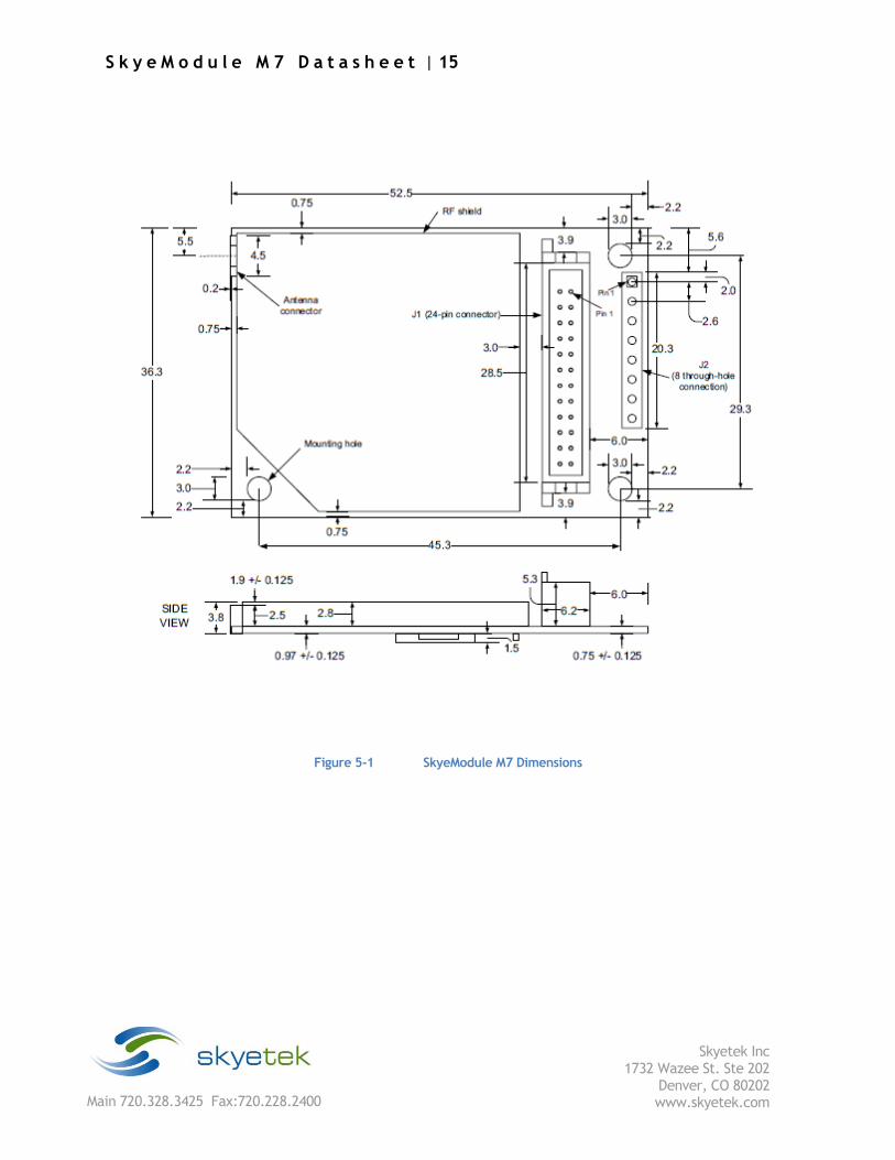
This list summarizes the SkyeModule M7 dimensions and clearances. See Figure 5-1 on page 12 for more
detailed dimensions.
Outside Dimensions: 36.3 mm x 52.5 mm = 1905.75 mm2
Height: 9.2 mm
Mounting holes: 3.0 mm diameter 29.3 mm center-to-center (width) 45.3 mm center-to-center (length)
Clearance: Approx. 2.2 mm between edges of mounting hole and edges of printed circuit board (PCB) (antenna connector side)
Approx. 2.3 mm between edge of mounting hole and front of PCB (main connector side)
Weight: 6.8 grams
NOTE – All drawing dimensions are in millimeters. Production units may vary slightly from the
measurements given.
S k y e M o d u l e M 7 D a t a s h e e t | 15
Skyetek Inc
1732 Wazee St. Ste 202 Denver, CO 80202 www.skyetek.com Main 720.328.3425 Fax:720.228.2400
Figure 5-1 SkyeModule M7 Dimensions
S k y e M o d u l e M 7 D a t a s h e e t | 16
Skyetek Inc
1732 Wazee St. Ste 202 Denver, CO 80202 www.skyetek.com Main 720.328.3425 Fax:720.228.2400
6 Pinning Information
Table 6-1 SkyeModule M7 Connector Specifications
Connector Type Manufacturer Manufacturer’s Part Number
Surface-mount protected header (receptacle on
module)
Hirose DF11Z-24DP-2V
MH counterpart to connect to module Hirose DF11Z-24DS-2V
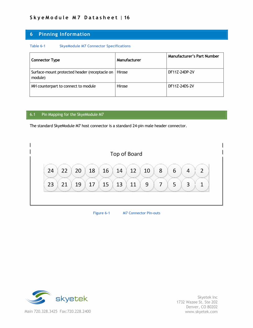
6.1 Pin Mapping for the SkyeModule M7
The standard SkyeModule M7 host connector is a standard 24-pin male header connector.
Figure 6-1 M7 Connector Pin-outs
S k y e M o d u l e M 7 D a t a s h e e t | 17
Skyetek Inc
1732 Wazee St. Ste 202 Denver, CO 80202 www.skyetek.com Main 720.328.3425 Fax:720.228.2400
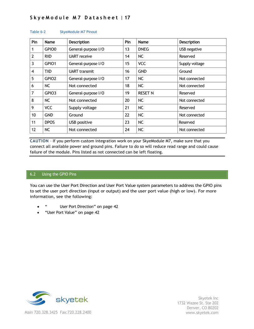
Table 6-2 SkyeModule M7 Pinout
Pin Name Description Pin Name Description
1 GPIO0 General-purpose I/O 13 DNEG USB negative
2 RXD UART receive 14 NC Reserved
3 GPIO1 General-purpose I/O 15 VCC Supply voltage
4 TXD UART transmit 16 GND Ground
5 GPIO2 General-purpose I/O 17 NC Not connected
6 NC Not connected 18 NC Not connected
7 GPIO3 General-purpose I/O 19 RESET N Reserved
8 NC Not connected 20 NC Not connected
9 VCC Supply voltage 21 NC Reserved
10 GND Ground 22 NC Not connected
11 DPOS USB positive 23 NC Reserved
12 NC Not connected 24 NC Not connected
CAUTION – If you perform custom integration work on your SkyeModule M7, make sure that you
connect all available power and ground pins. Failure to do so will reduce read range and could cause
failure of the module. Pins listed as not connected can be left floating.
6.2 Using the GPIO Pins
You can use the User Port Direction and User Port Value system parameters to address the GPIO pins
to set the user port direction (input or output) and the user port value (high or low). For more
information, see the following:
“ User Port Direction” on page 42
“User Port Value” on page 42
S k y e M o d u l e M 7 D a t a s h e e t | 18
Skyetek Inc
1732 Wazee St. Ste 202 Denver, CO 80202 www.skyetek.com Main 720.328.3425 Fax:720.228.2400
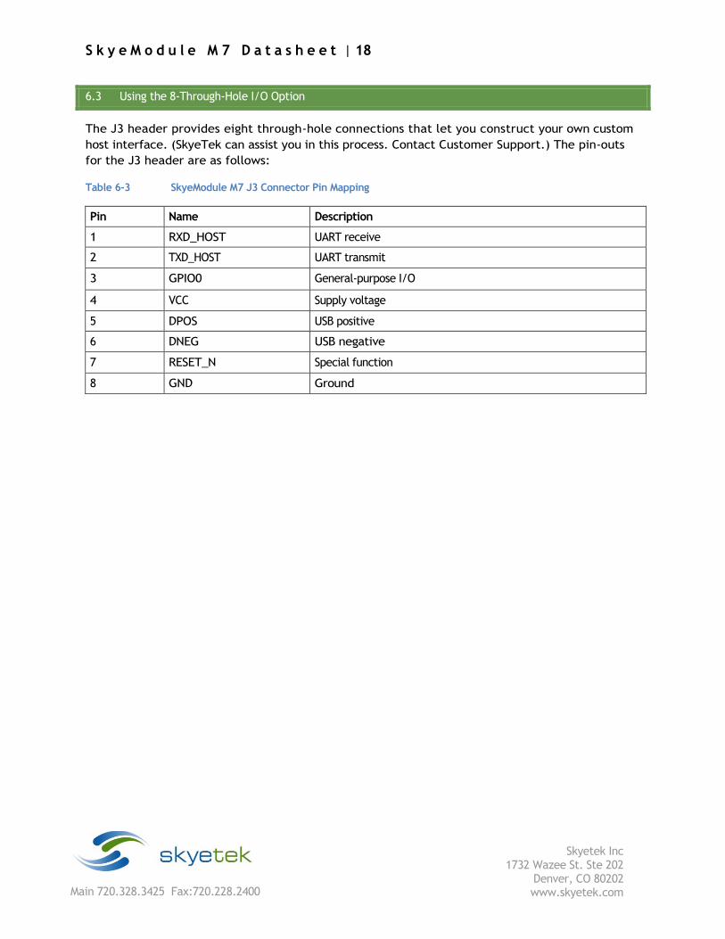
6.3 Using the 8-Through-Hole I/O Option
The J3 header provides eight through-hole connections that let you construct your own custom
host interface. (SkyeTek can assist you in this process. Contact Customer Support.) The pin-outs
for the J3 header are as follows:
Table 6-3 SkyeModule M7 J3 Connector Pin Mapping
Pin Name Description
1 RXD_HOST UART receive
2 TXD_HOST UART transmit
3 GPIO0 General-purpose I/O
4 VCC Supply voltage
5 DPOS USB positive
6 DNEG USB negative
7 RESET_N Special function
8 GND Ground
S k y e M o d u l e M 7 D a t a s h e e t | 19
Skyetek Inc
1732 Wazee St. Ste 202 Denver, CO 80202 www.skyetek.com Main 720.328.3425 Fax:720.228.2400
7 Environmental Specifications
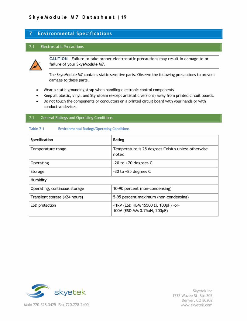
7.1 Electrostatic Precautions
CAUTION – Failure to take proper electrostatic precautions may result in damage to or
failure of your SkyeModule M7.
The SkyeModule M7 contains static-sensitive parts. Observe the following precautions to prevent
damage to these parts.
Wear a static grounding strap when handling electronic control components
Keep all plastic, vinyl, and Styrofoam (except antistatic versions) away from printed circuit boards.
Do not touch the components or conductors on a printed circuit board with your hands or with
conductive devices.
7.2 General Ratings and Operating Conditions
Table 7-1 Environmental Ratings/Operating Conditions
Specification Rating
Temperature range Temperature is 25 degrees Celsius unless otherwise
noted
Operating -20 to +70 degrees C
Storage -30 to +85 degrees C
Humidity
Operating, continuous storage 10-90 percent (non-condensing)
Transient storage (<24 hours) 5-95 percent maximum (non-condensing)
ESD protection <1kV (ESD HBM 15500 Ω, 100pF) –or-
100V (ESD MM 0.75uH, 200pF)
S k y e M o d u l e M 7 D a t a s h e e t | 20
Skyetek Inc
1732 Wazee St. Ste 202 Denver, CO 80202 www.skyetek.com Main 720.328.3425 Fax:720.228.2400
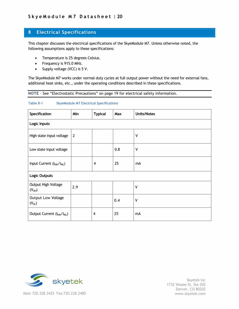
8 Electrical Specifications
This chapter discusses the electrical specifications of the SkyeModule M7. Unless otherwise noted, the
following assumptions apply to these specifications:
Temperature is 25 degrees Celsius.
Frequency is 915.0 MHz.
Supply voltage (VCC) is 5 V.
The SkyeModule M7 works under normal duty cycles at full output power without the need for external fans,
additional heat sinks, etc., under the operating conditions described in these specifications.
NOTE – See “Electrostatic Precautions” on page 19 for electrical safety information.
Table 8-1 SkyeModule M7 Electrical Specifications
Specification Min Typical Max Units/Notes
Logic Inputs
High state input voltage 2 V
Low state input voltage 0.8 V
Input Current (IINH/IINL) 4 25 mA
Logic Outputs
Output High Voltage
(VOH) 2.9 V
Output Low Voltage
(VOL) 0.4 V
Output Current (IINH/IINL) 4 25 mA
S k y e M o d u l e M 7 D a t a s h e e t | 21
Skyetek Inc
1732 Wazee St. Ste 202 Denver, CO 80202 www.skyetek.com Main 720.328.3425 Fax:720.228.2400
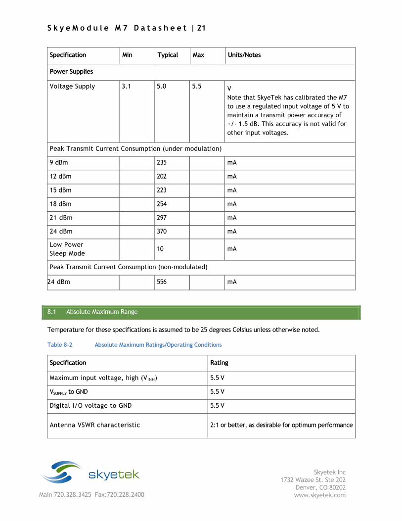
Specification Min Typical Max Units/Notes
Power Supplies
Voltage Supply 3.1 5.0 5.5 V
Note that SkyeTek has calibrated the M7
to use a regulated input voltage of 5 V to
maintain a transmit power accuracy of
+/- 1.5 dB. This accuracy is not valid for
other input voltages.
Peak Transmit Current Consumption (under modulation)
9 dBm 235 mA
12 dBm 202 mA
15 dBm 223 mA
18 dBm 254 mA
21 dBm 297 mA
24 dBm 370 mA
Low Power
Sleep Mode 10 mA
Peak Transmit Current Consumption (non-modulated)
24 dBm 556 mA
8.1 Absolute Maximum Range
Temperature for these specifications is assumed to be 25 degrees Celsius unless otherwise noted.
Table 8-2 Absolute Maximum Ratings/Operating Conditions
Specification Rating
Maximum input voltage, high (VINH) 5.5 V
VSUPPLY to GND 5.5 V
Digital I/O voltage to GND 5.5 V
Antenna VSWR characteristic 2:1 or better, as desirable for optimum performance
S k y e M o d u l e M 7 D a t a s h e e t | 22
Skyetek Inc
1732 Wazee St. Ste 202 Denver, CO 80202 www.skyetek.com Main 720.328.3425 Fax:720.228.2400
9 Host Interface Specifications
The following sections describe the power and host communication connections for the SkyeModule M7.
9.1 Host to Reader Interfaces
The SkyeModule M7 supports the following microcontroller host interfaces for easy integration into existing
systems:
TTL Serial
USB
The SkyeModule M7, when used with a host interface board, supports RS-232 and USB communications. The
host interface board provides a USB connector and a TTL-to-RS-232-level converter for the TTL host
interface. Each interface is software-selectable and only one host interface is active at a time.
The host interface is selected based on the power-up default value and can be changed at run time
using the Host Interface Type system parameter. The SkyeModule M7 operates under host control
using SkyeTek Protocol v3 sent over one of the host interfaces described in this chapter.
NOTE – SkyeModule M7s shipped with the SkyeTek Developer Kit are preset to use USB communications
and a power level of 21 dBm.
S k y e M o d u l e M 7 D a t a s h e e t | 23
Skyetek Inc
1732 Wazee St. Ste 202 Denver, CO 80202 www.skyetek.com Main 720.328.3425 Fax:720.228.2400
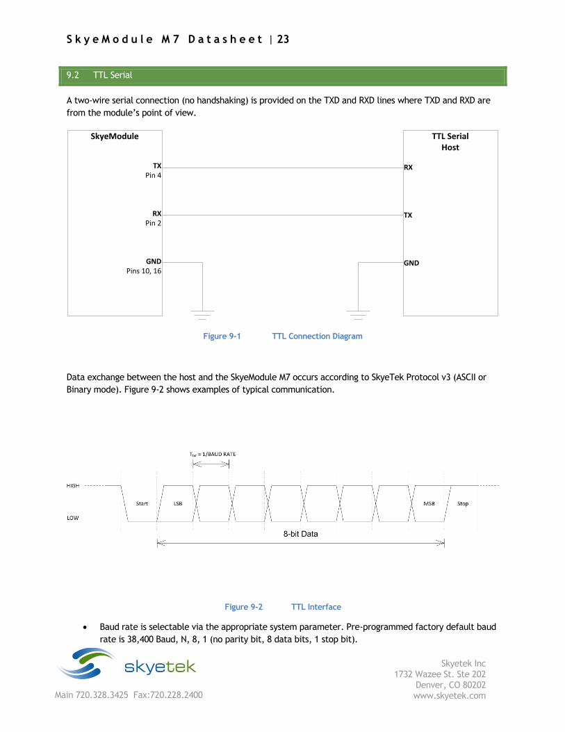
9.2 TTL Serial
A two-wire serial connection (no handshaking) is provided on the TXD and RXD lines where TXD and RXD are
from the module’s point of view.
SkyeModule
TX Pin 4
RX Pin 2
GNDPins 10, 16
TTL SerialHost
RX
TX
GND
Figure 9-1 TTL Connection Diagram
Data exchange between the host and the SkyeModule M7 occurs according to SkyeTek Protocol v3 (ASCII or
Binary mode). Figure 9-2 shows examples of typical communication.
Figure 9-2 TTL Interface
Baud rate is selectable via the appropriate system parameter. Pre-programmed factory default baud
rate is 38,400 Baud, N, 8, 1 (no parity bit, 8 data bits, 1 stop bit).

S k y e M o d u l e M 7 D a t a s h e e t | 24
Skyetek Inc
1732 Wazee St. Ste 202 Denver, CO 80202 www.skyetek.com Main 720.328.3425 Fax:720.228.2400
Bytes are transmitted least-significant bit (LSB) first using the typical serial data format of Start Bit
followed by 8 data bits followed by a Stop Bit.
The TTL connection supports bit rates from 9,600 to 115,200 baud, 8 data bits, no parity, 1 stop bit.
The option to add hardware flow control is not supported in this release.
Host to reader interface shall be RS-232 TTL level (non-inverted).
TTL low = 0 to 0.8V; TTL high = 2.0 to 5V.
S k y e M o d u l e M 7 D a t a s h e e t | 25
Skyetek Inc
1732 Wazee St. Ste 202 Denver, CO 80202 www.skyetek.com Main 720.328.3425 Fax:720.228.2400
9.3 USB 2.0
The SkyeModule M7 is seen by the host as a generic HID USB device.
The SkyeModule M7 is USB 2.0 High Speed compliant.
NOTE – When the SkyeModule M7 is USB-bus powered, maximum transit power should not exceed
20dBm. SkyeModule M7s shipped with the SkyeTek Development Kit are preset to use USB
communications and a power level of 20dBm.
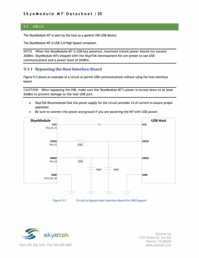
9.3.1 Bypassing the Host Interface Board
Figure 9-3 shows an example of a circuit to permit USB communications without using the host interface
board.
CAUTION – When bypassing the HIB, make sure the SkyeModule M7’s power is turned down to at least
20dBm to prevent damage to the host USB port.
SkyeTek Recommends that the power supply for the circuit provides 1A of current to ensure proper
operation.
Be sure to connect the power and ground if you are powering the M7 with USB power.
33Ω
33Ω
18pF 18pF
SkyeModuleVCC
Pins 9, 15
DPOS Pin 11
DNEG Pin 13
GNDPins 10, 16
USB HostVCC
DPOS
DNEG
GND
5V
Figure 9-3 Circuit to Bypass Host Interface Board for USB Support
S k y e M o d u l e M 7 D a t a s h e e t | 26
Skyetek Inc
1732 Wazee St. Ste 202 Denver, CO 80202 www.skyetek.com Main 720.328.3425 Fax:720.228.2400
10 Radio Specifications and Regional Compliance
10.1 RF Radio Power
To minimize power consumption for systems that have lower power requirements, the RF transmit
power of the SkyeModule M7 is user configurable from 9-24 dBm in steps of 3.0 dB with an accuracy of
+/-1.5 dB across a temperature range of -10 to +55 degrees Celsius. See Chapter 13, “Customizing
System Parameters,” for information on how to change the RF power level.
10.2 Frequency Range
The SkyeModule M7 is a multi-frequency device that operates in the 862-955 MHz range, which
spans the world’s major UHF RFID bands. See “Adjusting System Parameters” below for
information on changing operating frequency and region of operation of the M7.
10.3 Tag Protocols
The SkyeModule M7 supports the basic tag commands (identify, read, and write) for the EPC C1G2 (ISO18000-
6C) protocol.
NOTE – For the most current listing of supported tags and features, see the Tag Support list included in
the documentation folder installed from your distribution CD or on the SkyeTek Support Portal.
S k y e M o d u l e M 7 D a t a s h e e t | 27
Skyetek Inc
1732 Wazee St. Ste 202 Denver, CO 80202 www.skyetek.com Main 720.328.3425 Fax:720.228.2400
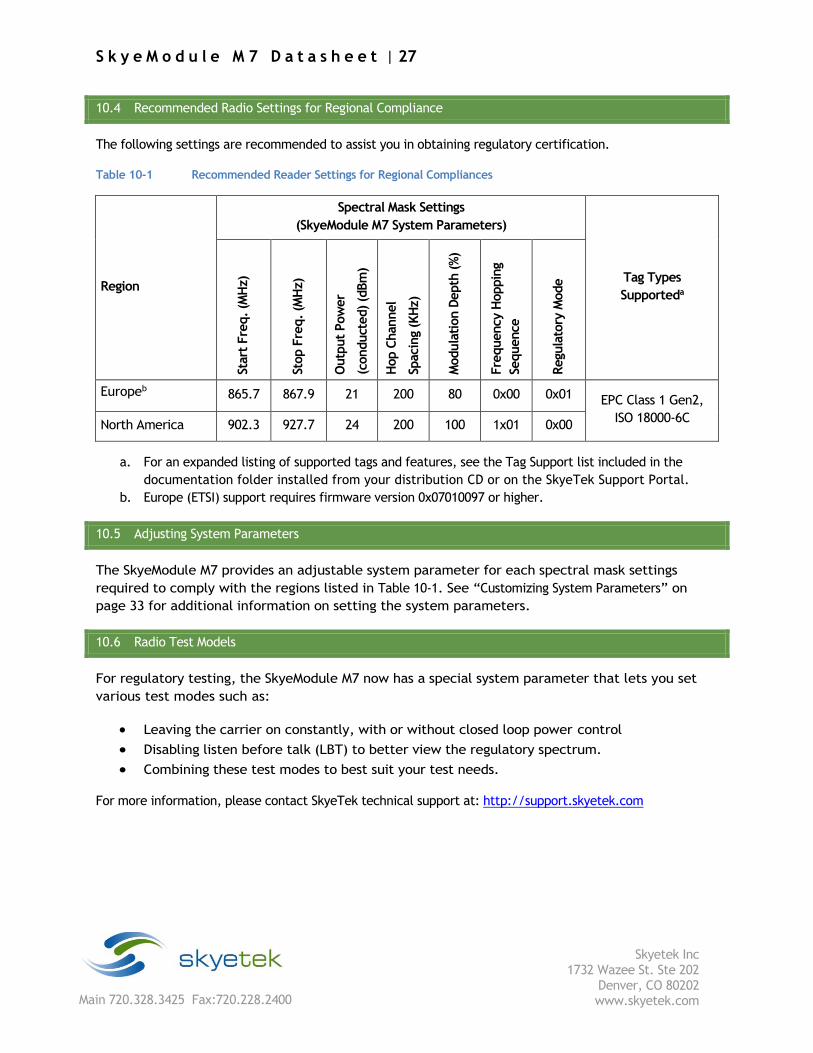
10.4 Recommended Radio Settings for Regional Compliance
The following settings are recommended to assist you in obtaining regulatory certification.
Table 10-1 Recommended Reader Settings for Regional Compliances
Region
Spectral Mask Settings
(SkyeModule M7 System Parameters)
Tag Types
Supporteda
Start
Fre
q. (M
Hz)
Stop F
req. (M
Hz)
Outp
ut
Pow
er
(conduct
ed) (d
Bm
)
Hop C
hannel
Spacin
g (K
Hz)
Modula
tion D
epth
(%
)
Fre
quency H
oppin
g
Sequence
Regu
lato
ry M
ode
Europeb 865.7 867.9 21 200 80 0x00 0x01 EPC Class 1 Gen2,
ISO 18000-6C North America 902.3 927.7 24 200 100 1x01 0x00
a. For an expanded listing of supported tags and features, see the Tag Support list included in the
documentation folder installed from your distribution CD or on the SkyeTek Support Portal.
b. Europe (ETSI) support requires firmware version 0x07010097 or higher.
10.5 Adjusting System Parameters
The SkyeModule M7 provides an adjustable system parameter for each spectral mask settings
required to comply with the regions listed in Table 10-1. See “Customizing System Parameters” on
page 33 for additional information on setting the system parameters.
10.6 Radio Test Models
For regulatory testing, the SkyeModule M7 now has a special system parameter that lets you set
various test modes such as:
Leaving the carrier on constantly, with or without closed loop power control
Disabling listen before talk (LBT) to better view the regulatory spectrum.
Combining these test modes to best suit your test needs.
For more information, please contact SkyeTek technical support at: http://support.skyetek.com
S k y e M o d u l e M 7 D a t a s h e e t | 28
Skyetek Inc
1732 Wazee St. Ste 202 Denver, CO 80202 www.skyetek.com Main 720.328.3425 Fax:720.228.2400
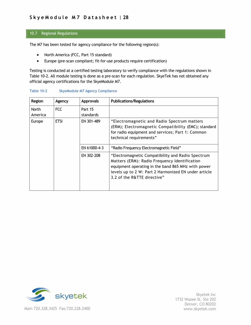
10.7 Regional Regulations
The M7 has been tested for agency compliance for the following region(s):
North America (FCC, Part 15 standard)
Europe (pre-scan compliant; fit-for-use products require certification)
Testing is conducted at a certified testing laboratory to verify compliance with the regulations shown in
Table 10-2. All module testing is done as a pre-scan for each regulation. SkyeTek has not obtained any
official agency certifications for the SkyeModule M7.
Table 10-2 SkyeModule M7 Agency Compliance
Region Agency Approvals Publications/Regulations
North
America
FCC Part 15
standards
Europe ETSI EN 301-489 “Electromagnetic and Radio Spectrum matters
(ERM); Electromagnetic Compatibility (EMC); standard
for radio equipment and services; Part 1: Common
technical requirements”
EN 61000-4-3 “Radio Frequency Electromagnetic Field”
EN 302-208 “Electromagnetic Compatibility and Radio Spectrum
Matters (ERM): Radio Frequency Identification
equipment operating in the band 865 MHz with power
levels up to 2 W: Part 2 Harmonized EN under article
3.2 of the R&TTE directive”
S k y e M o d u l e M 7 D a t a s h e e t | 29
Skyetek Inc
1732 Wazee St. Ste 202 Denver, CO 80202 www.skyetek.com Main 720.328.3425 Fax:720.228.2400
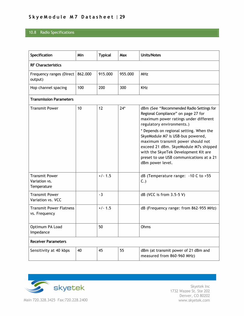
10.8 Radio Specifications
Specification Min Typical Max Units/Notes
RF Characteristics
Frequency ranges (Direct
output)
862.000 915.000 955.000 MHz
Hop channel spacing 100 200 300 KHz
Transmission Parameters
Transmit Power 10 12 24* dBm (See “Recommended Radio Settings for
Regional Compliance” on page 27 for
maximum power ratings under different
regulatory environments.)
* Depends on regional setting. When the
SkyeModule M7 is USB-bus powered,
maximum transmit power should not
exceed 21 dBm. SkyeModule M7s shipped
with the SkyeTek Development Kit are
preset to use USB communications at a 21
dBm power level.
Transmit Power
Variation vs.
Temperature
+/- 1.5 dB (Temperature range: -10 C to +55
C.)
Transmit Power
Variation vs. VCC ~3 dB (VCC is from 3.5-5 V)
Transmit Power Flatness
vs. Frequency +/- 1.5 dB (Frequency range: from 862-955 MHz)
Optimum PA Load
Impedance 50 Ohms
Receiver Parameters
Sensitivity at 40 kbps 40 45 55 dBm (at transmit power of 21 dBm and
measured from 860-960 MHz)
S k y e M o d u l e M 7 D a t a s h e e t | 30
Skyetek Inc
1732 Wazee St. Ste 202 Denver, CO 80202 www.skyetek.com Main 720.328.3425 Fax:720.228.2400
11 Antenna Options
The SkyeModule M7 supports any 50 Ohm antenna tuned to the correct frequency range. Read range is highly
dependent on antenna selection, tag selection, and operating environment.
Read range depends on your specific settings, including:
Environment (to maximize accuracy for testing, SkyeTek recommends that you use an outdoor free-
space test)
Antenna gain: a higher-gain antenna provides a longer read range. However, this longer range is
achieved through a smaller beam width, which in turn reduces the size of the read field, affecting
read reliability.
Antenna cable length: antenna-cable gain/loss is approximately -0.49 dB/meter (-0.15 dB/foot) for a
standard RG58 coaxial cable.
RF power: maximum RF power is 24 dBm.
Frequency hopping settings (depends on antenna)
Antenna polarization
Tag orientation
Tag type, manufacturer, and individual tag
Tag mounting surface
Tag dynamics (speed, moving, rotating)
NOTE – The MMCX antenna connector for the SkyeModule M7 allows quick connections but can let a
loose antenna cable rotate, yaw, or pitch in the connector socket if you do not secure the cable. Cable
motion increases the VSWR to the radio receiver and degrades performance. Make sure that you
provide strain relief for the antenna cable to prevent any motion or mechanical stress at the MMCX
connector.
S k y e M o d u l e M 7 D a t a s h e e t | 31
Skyetek Inc
1732 Wazee St. Ste 202 Denver, CO 80202 www.skyetek.com Main 720.328.3425 Fax:720.228.2400
12 Communication Specifications
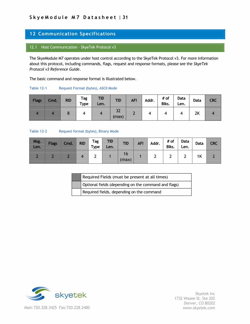
12.1 Host Communication – SkyeTek Protocol v3
The SkyeModule M7 operates under host control according to the SkyeTek Protocol v3. For more information
about this protocol, including commands, flags, request and response formats, please see the SkyeTek
Protocol v3 Reference Guide.
The basic command and response format is illustrated below.
Table 12-1 Request Format (bytes), ASCII Mode
Flags Cmd. RID Tag
Type
TID
Len. TID AFI Addr.
# of
Blks.
Data
Len. Data CRC
4 4 8 4 4 32
(max) 2 4 4 4 2K 4
Table 12-2 Request format (bytes), Binary Mode
Msg.
Len. Flags Cmd. RID
Tag
Type
TID
Len. TID AFI Addr.
# of
Blks.
Data
Len. Data CRC
2 2 2 4 2 1 16
(max) 1 2 2 2 1K 2
Required Fields (must be present at all times)
Optional fields (depending on the command and flags)
Required fields, depending on the command
S k y e M o d u l e M 7 D a t a s h e e t | 32
Skyetek Inc
1732 Wazee St. Ste 202 Denver, CO 80202 www.skyetek.com Main 720.328.3425 Fax:720.228.2400
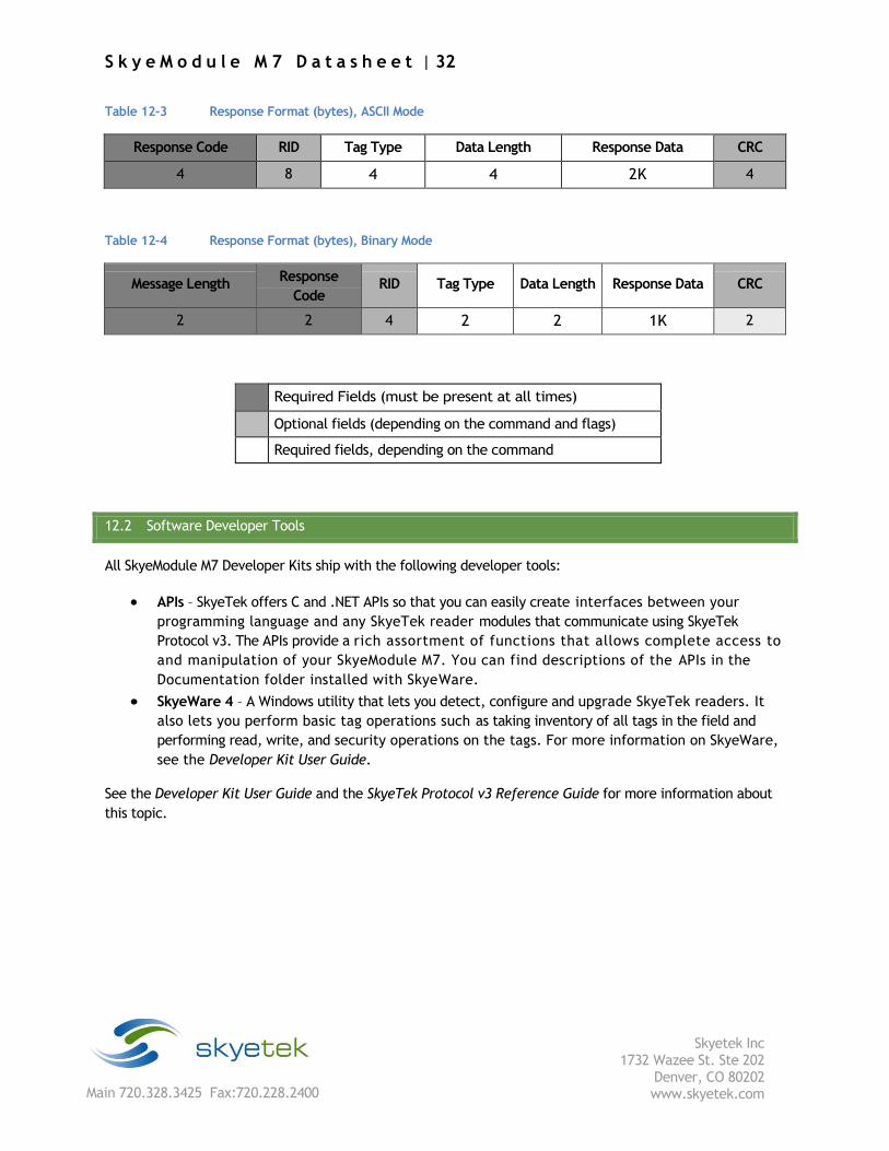
Table 12-3 Response Format (bytes), ASCII Mode
Response Code RID Tag Type Data Length Response Data CRC
4 8 4 4 2K 4
Table 12-4 Response Format (bytes), Binary Mode
Message Length Response
Code RID Tag Type Data Length Response Data CRC
2 2 4 2 2 1K 2
Required Fields (must be present at all times)
Optional fields (depending on the command and flags)
Required fields, depending on the command
12.2 Software Developer Tools
All SkyeModule M7 Developer Kits ship with the following developer tools:
APIs – SkyeTek offers C and .NET APIs so that you can easily create interfaces between your
programming language and any SkyeTek reader modules that communicate using SkyeTek
Protocol v3. The APIs provide a rich assortment of functions that allows complete access to
and manipulation of your SkyeModule M7. You can find descriptions of the APIs in the
Documentation folder installed with SkyeWare.
SkyeWare 4 – A Windows utility that lets you detect, configure and upgrade SkyeTek readers. It
also lets you perform basic tag operations such as taking inventory of all tags in the field and
performing read, write, and security operations on the tags. For more information on SkyeWare,
see the Developer Kit User Guide.
See the Developer Kit User Guide and the SkyeTek Protocol v3 Reference Guide for more information about
this topic.

S k y e M o d u l e M 7 D a t a s h e e t | 33
Skyetek Inc
1732 Wazee St. Ste 202 Denver, CO 80202 www.skyetek.com Main 720.328.3425 Fax:720.228.2400
13 Customizing System Parameters
System parameters let you configure reader settings to customize them for your environment. You
can temporarily alter parameters in memory or change the default values that are stored on the
SkyeModule M7 EEPROM. The following table summarizes the parameters for the SkyeModule M7.
(See “System Parameter Descriptions” on page 39 for detailed information on each parameter.
Table 13-1 System Parameter Addresses, Lengths, and Default Values
Parameter Address Hex # of
Bytes Default Value
Serial Number 0x0000 4 0x00000000
Firmware Version 0x0001 4 0xXXXXXXXX (depends on release)
Hardware Version 0x0002 4 0xXXXXXXXX (depends on release)
Product Code 0x0003 2 0x0007 (M7)
Reader ID 0x0004 4 0xFFFFFFFF
Reader Name 0x0005 32 SkyeModule M7 (in hex)
Host Interface Type 0x0006 1 0x01 (for UART1)
Host Interface Baud Rate 0x0007 1 0x02 (38400)
User Port Direction 0x0008 1 0x00 (GPIO pins are outputs)
User Port Value 0x0009 1 0x00 (GPIO pins are logic low)
MUX Control 0x000A 1 0x00 (no multiplexer)
Operating Mode 0x000C 1 0x00 (no active mode)
Command Retry 0x0011 1 0x05 (five retries)
Power Level 0x0012 1 0xA0 (21 dBm)
Current Frequency 0x0030 4 0x3689CAC0 (915 MHz)
Start Frequency 0x0031 4 0x35C80160 (902.3 MHz)
Stop Frequency 0x0032 4 0x374B9420 (927.7 MHz)
Hop Channel Spacing 0x0034 4 0x00030D40 (200 KHz)
Frequency Hopping Sequence 0x0035 1 0x01 (pseudo-random)
Modulation Depth 0x0036 1 0x64 (100%)
Regulatory Mode 0x0037 1 0x00 (FCC/no pulse shaping)
LBT Antenna Gain 0x0037 1 0x00 (no LBT antenna gain)
13.1 Changing System Parameters
CAUTION – Changing system parameter values – especially the default values – can render your
SkyeModule M7 nonoperational in your environment. Research, record, and test all planned changes to
make sure they are compatible with your system.
You can read or write system parameters via the following commands:
S k y e M o d u l e M 7 D a t a s h e e t | 34
Skyetek Inc
1732 Wazee St. Ste 202 Denver, CO 80202 www.skyetek.com Main 720.328.3425 Fax:720.228.2400
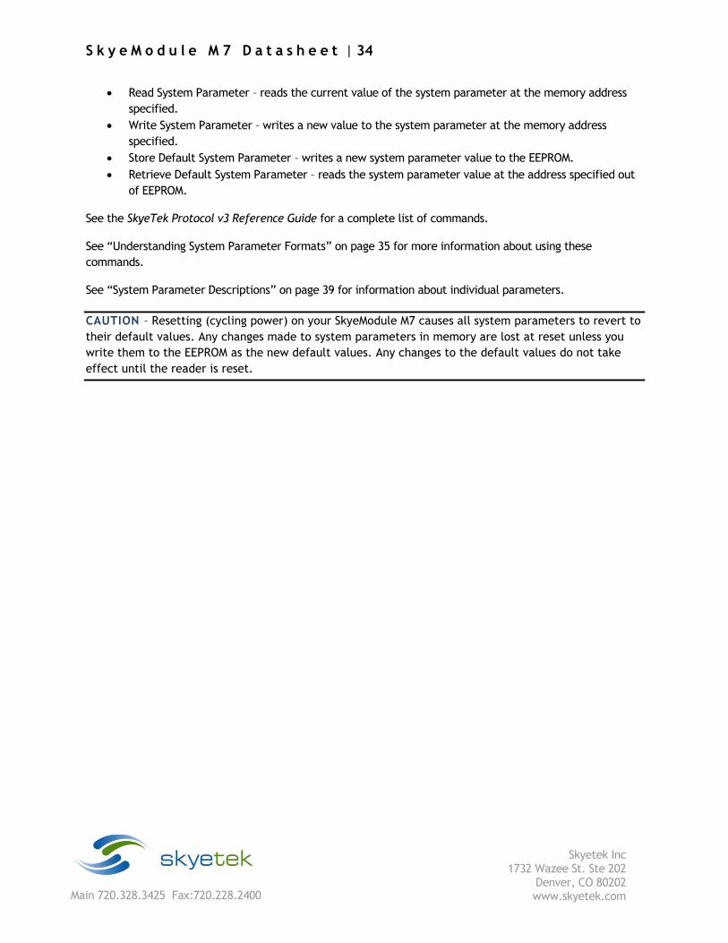
Read System Parameter – reads the current value of the system parameter at the memory address
specified.
Write System Parameter – writes a new value to the system parameter at the memory address
specified.
Store Default System Parameter – writes a new system parameter value to the EEPROM.
Retrieve Default System Parameter – reads the system parameter value at the address specified out
of EEPROM.
See the SkyeTek Protocol v3 Reference Guide for a complete list of commands.
See “Understanding System Parameter Formats” on page 35 for more information about using these
commands.
See “System Parameter Descriptions” on page 39 for information about individual parameters.
CAUTION – Resetting (cycling power) on your SkyeModule M7 causes all system parameters to revert to
their default values. Any changes made to system parameters in memory are lost at reset unless you
write them to the EEPROM as the new default values. Any changes to the default values do not take
effect until the reader is reset.
S k y e M o d u l e M 7 D a t a s h e e t | 35
Skyetek Inc
1732 Wazee St. Ste 202 Denver, CO 80202 www.skyetek.com Main 720.328.3425 Fax:720.228.2400
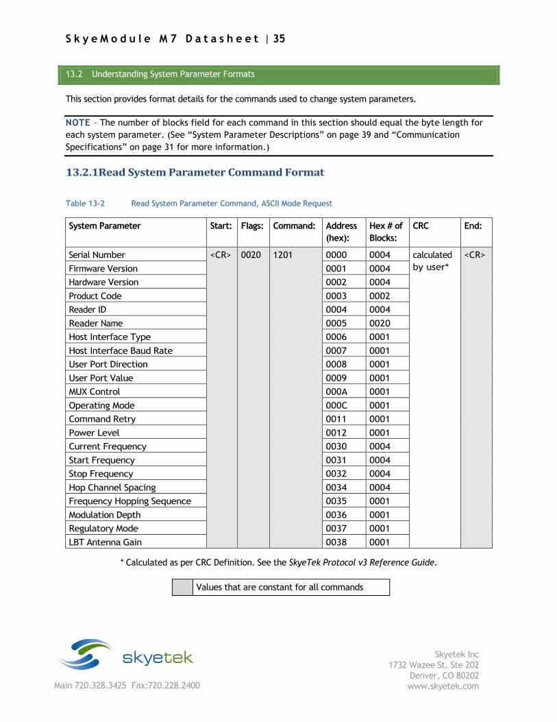
13.2 Understanding System Parameter Formats
This section provides format details for the commands used to change system parameters.
NOTE – The number of blocks field for each command in this section should equal the byte length for
each system parameter. (See “System Parameter Descriptions” on page 39 and “Communication
Specifications” on page 31 for more information.)
13.2.1 Read System Parameter Command Format
Table 13-2 Read System Parameter Command, ASCII Mode Request
System Parameter Start: Flags: Command: Address
(hex):
Hex # of
Blocks:
CRC End:
Serial Number <CR> 0020 1201 0000 0004 calculated
by user*
<CR>
Firmware Version 0001 0004
Hardware Version 0002 0004
Product Code 0003 0002
Reader ID 0004 0004
Reader Name 0005 0020
Host Interface Type 0006 0001
Host Interface Baud Rate 0007 0001
User Port Direction 0008 0001
User Port Value 0009 0001
MUX Control 000A 0001
Operating Mode 000C 0001
Command Retry 0011 0001
Power Level 0012 0001
Current Frequency 0030 0004
Start Frequency 0031 0004
Stop Frequency 0032 0004
Hop Channel Spacing 0034 0004
Frequency Hopping Sequence 0035 0001
Modulation Depth 0036 0001
Regulatory Mode 0037 0001
LBT Antenna Gain 0038 0001
* Calculated as per CRC Definition. See the SkyeTek Protocol v3 Reference Guide.
Values that are constant for all commands
S k y e M o d u l e M 7 D a t a s h e e t | 36
Skyetek Inc
1732 Wazee St. Ste 202 Denver, CO 80202 www.skyetek.com Main 720.328.3425 Fax:720.228.2400
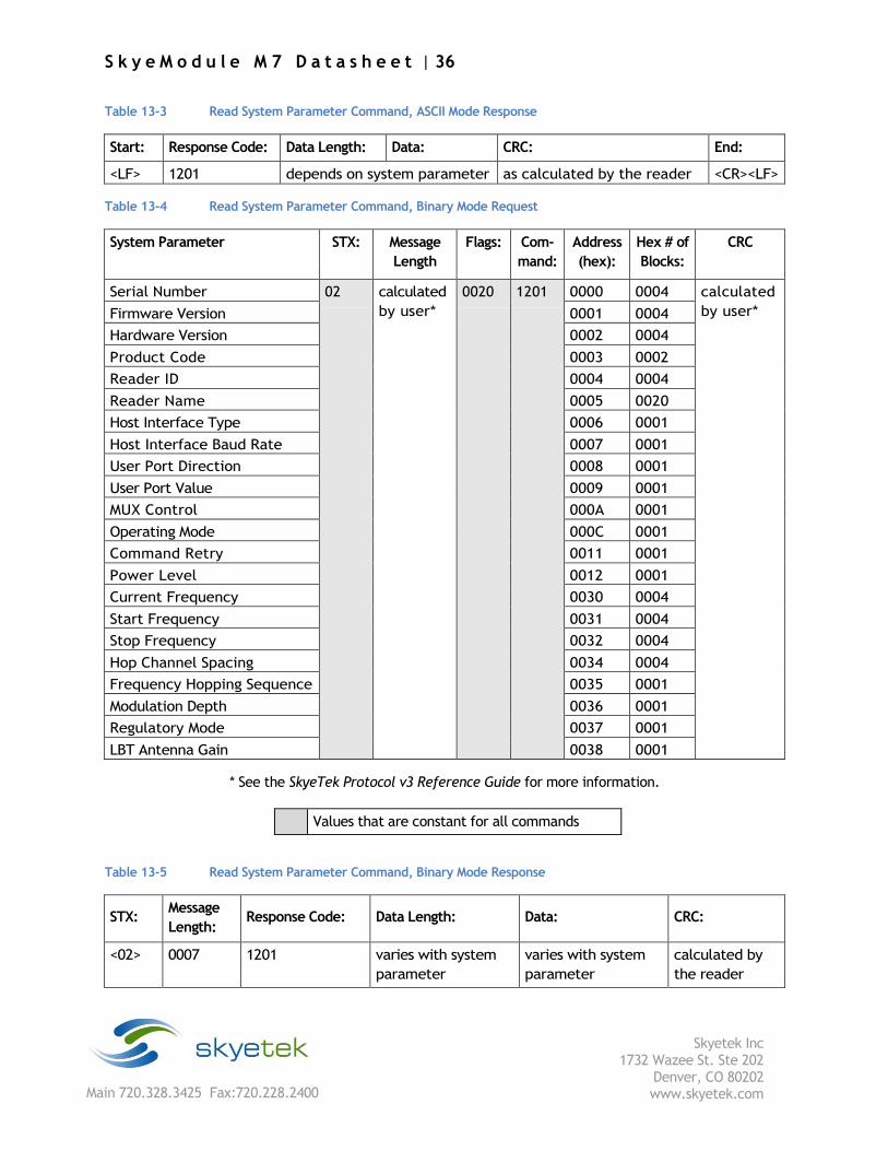
Table 13-3 Read System Parameter Command, ASCII Mode Response
Start: Response Code: Data Length: Data: CRC: End:
<LF> 1201 depends on system parameter as calculated by the reader <CR><LF> Table 13-4 Read System Parameter Command, Binary Mode Request
System Parameter STX: Message
Length
Flags: Com-
mand:
Address
(hex):
Hex # of
Blocks:
CRC
Serial Number 02 calculated
by user*
0020 1201 0000 0004 calculated
by user* Firmware Version 0001 0004
Hardware Version 0002 0004
Product Code 0003 0002
Reader ID 0004 0004
Reader Name 0005 0020
Host Interface Type 0006 0001
Host Interface Baud Rate 0007 0001
User Port Direction 0008 0001
User Port Value 0009 0001
MUX Control 000A 0001
Operating Mode 000C 0001
Command Retry 0011 0001
Power Level 0012 0001
Current Frequency 0030 0004
Start Frequency 0031 0004
Stop Frequency 0032 0004
Hop Channel Spacing 0034 0004
Frequency Hopping Sequence 0035 0001
Modulation Depth 0036 0001
Regulatory Mode 0037 0001
LBT Antenna Gain 0038 0001
* See the SkyeTek Protocol v3 Reference Guide for more information.
Values that are constant for all commands
Table 13-5 Read System Parameter Command, Binary Mode Response
STX: Message
Length: Response Code: Data Length: Data: CRC:
<02> 0007 1201 varies with system
parameter
varies with system
parameter
calculated by
the reader
S k y e M o d u l e M 7 D a t a s h e e t | 37
Skyetek Inc
1732 Wazee St. Ste 202 Denver, CO 80202 www.skyetek.com Main 720.328.3425 Fax:720.228.2400
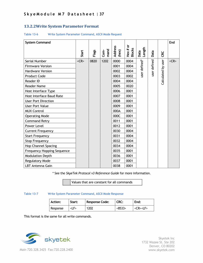
13.2.2 Write System Parameter Format Table 13-6 Write System Parameter Command, ASCII Mode Request
System Command
Start
Fla
gs
Com
-
mand
Addre
ss
(hex)
Hex #
or
Blo
cks
Data
Lengt
h
Data
CRC
End
Serial Number <CR> 0820 1202 0000 0004
use
r defined*
use
r defined
Calc
ula
ted b
y use
r
<CR>
Firmware Version 0001 0004
Hardware Version 0002 0004
Product Code 0003 0002
Reader ID 0004 0004
Reader Name 0005 0020
Host Interface Type 0006 0001
Host Interface Baud Rate 0007 0001
User Port Direction 0008 0001
User Port Value 0009 0001
MUX Control 000A 0001
Operating Mode 000C 0001
Command Retry 0011 0001
Power Level 0012 0001
Current Frequency 0030 0004
Start Frequency 0031 0004
Stop Frequency 0032 0004
Hop Channel Spacing 0034 0004
Frequency Hopping Sequence 0035 0001
Modulation Depth 0036 0001
Regulatory Mode 0037 0001
LBT Antenna Gain 0038 0001
* See the SkyeTek Protocol v3 Reference Guide for more information.
Values that are constant for all commands
Table 13-7 Write System Parameter Command, ASCII Mode Response
Action: Start: Response Code: CRC: End:
Response <LF> 1202 <8533> <CR><LF>
This format is the same for all write commands.

S k y e M o d u l e M 7 D a t a s h e e t | 38
Skyetek Inc
1732 Wazee St. Ste 202 Denver, CO 80202 www.skyetek.com Main 720.328.3425 Fax:720.228.2400
Table 13-8 Write System Parameter Command, Binary Mode Request
System Parameter STX: Message
Length:
Flags: Com-
mand:
Address
(hex):
Hex # of
Blocks:
CRC
Serial Number 02
calc
ula
ted b
y use
r*
0820 1202 0000 0004
calc
ula
ted b
y use
r*
Firmware Version 0001 0004
Hardware Version 0002 0004
Product Code 0003 0002
Reader ID 0004 0004
Reader Name 0005 0020
Host Interface Type 0006 0001
Host Interface Baud Rate 0007 0001
User Port Direction 0008 0001
User Port Value 0009 0001
MUX Control 000A 0001
Operating Mode 000C 0001
Command Retry 0011 0001
Power Level 0012 0001
Current Frequency 0030 0004
Start Frequency 0031 0004
Stop Frequency 0032 0004
Hop Channel Spacing 0034 0004
Frequency Hopping Sequence 0035 0001
Modulation Depth 0036 0001
Regulatory Mode 0037 0001
LBT Antenna Gain 0038 0001
* See the SkyeTek Protocol v3 Reference Guide for more information.
Values that are constant for all commands
Table 13-9 Write System Parameter Command, Binary Mode Response
STX: Message Length: Response Code: CRC:
<02> 0004 1202 <E652>
This format is the same for all write commands.
S k y e M o d u l e M 7 D a t a s h e e t | 39
Skyetek Inc
1732 Wazee St. Ste 202 Denver, CO 80202 www.skyetek.com Main 720.328.3425 Fax:720.228.2400
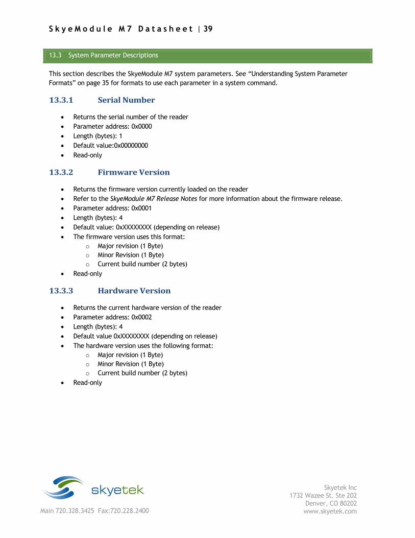
13.3 System Parameter Descriptions
This section describes the SkyeModule M7 system parameters. See “Understanding System Parameter
Formats” on page 35 for formats to use each parameter in a system command.
13.3.1 Serial Number
Returns the serial number of the reader
Parameter address: 0x0000
Length (bytes): 1
Default value:0x00000000
Read-only
13.3.2 Firmware Version
Returns the firmware version currently loaded on the reader
Refer to the SkyeModule M7 Release Notes for more information about the firmware release.
Parameter address: 0x0001
Length (bytes): 4
Default value: 0xXXXXXXXX (depending on release)
The firmware version uses this format:
o Major revision (1 Byte)
o Minor Revision (1 Byte)
o Current build number (2 bytes)
Read-only
13.3.3 Hardware Version
Returns the current hardware version of the reader
Parameter address: 0x0002
Length (bytes): 4
Default value 0xXXXXXXXX (depending on release)
The hardware version uses the following format:
o Major revision (1 Byte)
o Minor Revision (1 Byte)
o Current build number (2 bytes)
Read-only
S k y e M o d u l e M 7 D a t a s h e e t | 40
Skyetek Inc
1732 Wazee St. Ste 202 Denver, CO 80202 www.skyetek.com Main 720.328.3425 Fax:720.228.2400
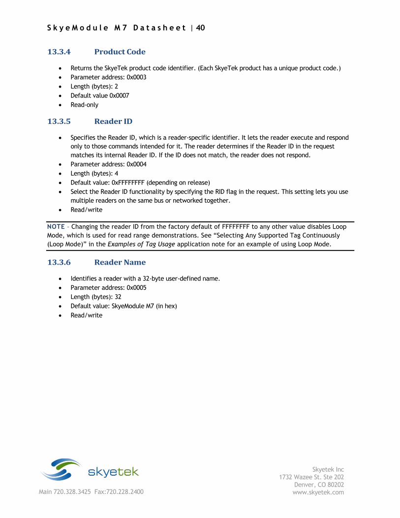
13.3.4 Product Code
Returns the SkyeTek product code identifier. (Each SkyeTek product has a unique product code.)
Parameter address: 0x0003
Length (bytes): 2
Default value 0x0007
Read-only
13.3.5 Reader ID
Specifies the Reader ID, which is a reader-specific identifier. It lets the reader execute and respond
only to those commands intended for it. The reader determines if the Reader ID in the request
matches its internal Reader ID. If the ID does not match, the reader does not respond.
Parameter address: 0x0004
Length (bytes): 4
Default value: 0xFFFFFFFF (depending on release)
Select the Reader ID functionality by specifying the RID flag in the request. This setting lets you use
multiple readers on the same bus or networked together.
Read/write
NOTE – Changing the reader ID from the factory default of FFFFFFFF to any other value disables Loop
Mode, which is used for read range demonstrations. See “Selecting Any Supported Tag Continuously
(Loop Mode)” in the Examples of Tag Usage application note for an example of using Loop Mode.
13.3.6 Reader Name
Identifies a reader with a 32-byte user-defined name.
Parameter address: 0x0005
Length (bytes): 32
Default value: SkyeModule M7 (in hex)
Read/write
S k y e M o d u l e M 7 D a t a s h e e t | 41
Skyetek Inc
1732 Wazee St. Ste 202 Denver, CO 80202 www.skyetek.com Main 720.328.3425 Fax:720.228.2400
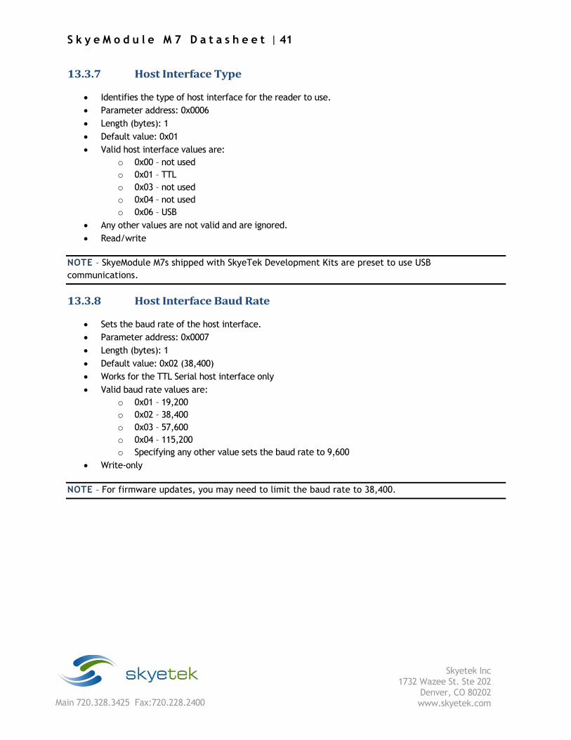
13.3.7 Host Interface Type
Identifies the type of host interface for the reader to use.
Parameter address: 0x0006
Length (bytes): 1
Default value: 0x01
Valid host interface values are:
o 0x00 – not used
o 0x01 – TTL
o 0x03 – not used
o 0x04 – not used
o 0x06 – USB
Any other values are not valid and are ignored.
Read/write
NOTE – SkyeModule M7s shipped with SkyeTek Development Kits are preset to use USB
communications.
13.3.8 Host Interface Baud Rate
Sets the baud rate of the host interface.
Parameter address: 0x0007
Length (bytes): 1
Default value: 0x02 (38,400)
Works for the TTL Serial host interface only
Valid baud rate values are:
o 0x01 – 19,200
o 0x02 – 38,400
o 0x03 – 57,600
o 0x04 – 115,200
o Specifying any other value sets the baud rate to 9,600
Write-only
NOTE – For firmware updates, you may need to limit the baud rate to 38,400.
S k y e M o d u l e M 7 D a t a s h e e t | 42
Skyetek Inc
1732 Wazee St. Ste 202 Denver, CO 80202 www.skyetek.com Main 720.328.3425 Fax:720.228.2400
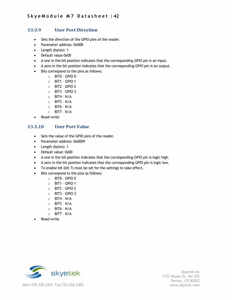
13.3.9 User Port Direction
Sets the direction of the GPIO pins of the reader.
Parameter address: 0x008
Length (bytes): 1
Default value 0x00
A one in the bit position indicates that the corresponding GPIO pin is an input.
A zero in the bit position indicates that the corresponding GPIO pin is an output.
Bits correspond to the pins as follows:
o BIT0 – GPIO 0
o BIT1 – GPIO 1
o BIT2 – GPIO 2
o BIT3 – GPIO 3
o BIT4 – N/A
o BIT5 – N/A
o BIT6 – N/A
o BIT7 – N/A
Read/write
13.3.10 User Port Value
Sets the value of the GPIO pins of the reader.
Parameter address: 0x0009
Length (bytes): 1
Default value: 0x00
A one in the bit position indicates that the corresponding GPIO pin is logic high.
A zero in the bit position indicates that the corresponding GPIO pin is logic low.
To enable bit (bit 7) must be set for the settings to take effect.
Bits correspond to the pins as follows:
o BIT0 – GPIO 0
o BIT1 – GPIO 1
o BIT2 – GPIO 2
o BIT3 – GPIO 3
o BIT4 – N/A
o BIT5 – N/A
o BIT6 – N/A
o BIT7 – N/A
Read/write
S k y e M o d u l e M 7 D a t a s h e e t | 43
Skyetek Inc
1732 Wazee St. Ste 202 Denver, CO 80202 www.skyetek.com Main 720.328.3425 Fax:720.228.2400
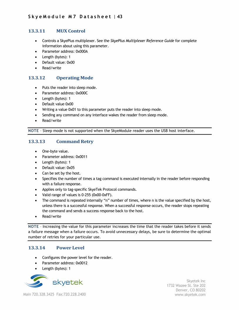
13.3.11 MUX Control
Controls a SkyePlus multiplexer. See the SkyePlus Multiplexer Reference Guide for complete
information about using this parameter.
Parameter address: 0x000A
Length (bytes): 1
Default value: 0x00
Read/write
13.3.12 Operating Mode
Puts the reader into sleep mode.
Parameter address: 0x000C
Length (bytes): 1
Default value 0x00
Writing a value 0x01 to this parameter puts the reader into sleep mode.
Sending any command on any interface wakes the reader from sleep mode.
Read/write
NOTE – Sleep mode is not supported when the SkyeModule reader uses the USB host interface.
13.3.13 Command Retry
One-byte value.
Parameter address: 0x0011
Length (bytes): 1
Default value: 0x05
Can be set by the host.
Specifies the number of times a tag command is executed internally in the reader before responding
with a failure response.
Applies only to tag-specific SkyeTek Protocol commands.
Valid range of values is 0-255 (0x00-0xFF).
The command is repeated internally “n” number of times, where n is the value specified by the host,
unless there is a successful response. When a successful response occurs, the reader stops repeating
the command and sends a success response back to the host.
Read/write
NOTE – Increasing the value for this parameter increases the time that the reader takes before it sends
a failure message when a failure occurs. To avoid unnecessary delays, be sure to determine the optimal
number of retries for your particular use.
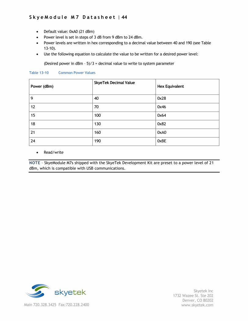
13.3.14 Power Level
Configures the power level for the reader.
Parameter address: 0x0012
Length (bytes): 1
S k y e M o d u l e M 7 D a t a s h e e t | 44
Skyetek Inc
1732 Wazee St. Ste 202 Denver, CO 80202 www.skyetek.com Main 720.328.3425 Fax:720.228.2400
Default value: 0xA0 (21 dBm)
Power level is set in steps of 3 dB from 9 dBm to 24 dBm.
Power levels are written in hex corresponding to a decimal value between 40 and 190 (see Table
13-10).
Use the following equation to calculate the value to be written for a desired power level:
(Desired power in dBm – 5)/3 = decimal value to write to system parameter
Table 13-10 Common Power Values
Power (dBm) SkyeTek Decimal Value
Hex Equivalent
9 40 0x28
12 70 0x46
15 100 0x64
18 130 0x82
21 160 0xA0
24 190 0xBE
Read/write
NOTE – SkyeModule M7s shipped with the SkyeTek Development Kit are preset to a power level of 21
dBm, which is compatible with USB communications.
S k y e M o d u l e M 7 D a t a s h e e t | 45
Skyetek Inc
1732 Wazee St. Ste 202 Denver, CO 80202 www.skyetek.com Main 720.328.3425 Fax:720.228.2400
13.3.15 Current Frequency
Sets the current frequency with which the reader detects (singulates) a tag.
Parameter address: 0x0030
Length (bytes): 4
Default value: 0x3689CAC0 (915 MHz)
This parameter is a 4-byte hex equivalent of the frequency. Table 13-11 shows hex values for
commonly used frequencies.
Read/write
NOTE – See “Recommended Radio Settings for Regional Compliance” on page 27 to view compliance
information and recommended reader settings.
13.3.16 Start Frequency
Sets the low end of the frequency range under which the reader operates.
Parameter address: 0x0031
Length (bytes): 4
Default value: 0x35C80160 (902.3 MHz)
This parameter is written with a 4-byte hex equivalent of the frequency desired. See Table 13-11 for
commonly used frequencies and their hex values.
To enable frequency hopping, set a frequency range using the Start Frequency and Stop Frequency
system parameters. Then use the Frequency Hopping Sequence parameter to set the frequency
hopping mode (either sequential or pseudo-random). To disable frequency hopping, set the Start
Frequency and Stop Frequency parameter to the same value.
Read/write
NOTE – See “Recommended Radio Settings for Regional Compliance” on page 27 to view compliance
information and recommended reader settings.
S k y e M o d u l e M 7 D a t a s h e e t | 46
Skyetek Inc
1732 Wazee St. Ste 202 Denver, CO 80202 www.skyetek.com Main 720.328.3425 Fax:720.228.2400
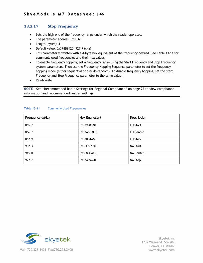
13.3.17 Stop Frequency
Sets the high end of the frequency range under which the reader operates.
The parameter address: 0x0032
Length (bytes): 4
Default value: 0x374B9420 (927.7 MHz)
This parameter is written with a 4-byte hex equivalent of the frequency desired. See Table 13-11 for
commonly used frequencies and their hex values.
To enable frequency hopping, set a frequency range using the Start Frequency and Stop Frequency
system parameters. Then use the Frequency Hopping Sequence parameter to set the frequency
hopping mode (either sequential or pseudo-random). To disable frequency hopping, set the Start
Frequency and Stop Frequency parameter to the same value.
Read/write
NOTE – See “Recommended Radio Settings for Regional Compliance” on page 27 to view compliance
information and recommended reader settings.
Table 13-11 Commonly Used Frequencies
Frequency (MHz) Hex Equivalent Description
865.7 0x339988A0 EU Start
866.7 0x33A8CAE0 EU Center
867.9 0x33BB1A60 EU Stop
902.3 0x35C80160 NA Start
915.0 0x3689CAC0 NA Center
927.7 0x374B9420 NA Stop
S k y e M o d u l e M 7 D a t a s h e e t | 47
Skyetek Inc
1732 Wazee St. Ste 202 Denver, CO 80202 www.skyetek.com Main 720.328.3425 Fax:720.228.2400
13.3.18 Hop Channel Spacing
Controls the hop channel spacing when frequency hopping is enabled.
Parameter address: 0x0034
Length (bytes): 4
Default value: 0x00030D40 (200 KHz)
To enable frequency hopping, set a frequency range using the Start Frequency and Stop Frequency
system parameters. Then use the Frequency Hopping Sequence parameter to set the frequency
hopping mode (either sequential or pseudo-random). To disable frequency hopping, set the Start
Frequency and Stop Frequency parameter to the same value.
Read/write
NOTE – See “Recommended Radio Settings for Regional Compliance” on page 27 to view compliance
information and recommended reader settings.
13.3.19 Frequency Hopping Sequence
Switches the hopping sequence between pseudo-random and sequential mode.
Parameter address: 0x0035
Length (bytes): 1
Default value: 0x01 (pseudo-random)
To set the reader to sequential hopping mode, write 0x00 to this parameter.
To reset the reader to pseudo-random hopping sequence, write 0x01 to this parameter.
To enable frequency hopping, set a frequency range using the Start Frequency and Stop Frequency
system parameters. Then use the Frequency Hopping Sequence parameter to set the frequency
hopping mode (either sequential or pseudo-random). To disable frequency hopping, set the Start
Frequency and Stop Frequency parameter to the same value.
Read/write
NOTE – See “Recommended Radio Settings for Regional Compliance” on page 27 to view compliance
information and recommended reader settings.
S k y e M o d u l e M 7 D a t a s h e e t | 48
Skyetek Inc
1732 Wazee St. Ste 202 Denver, CO 80202 www.skyetek.com Main 720.328.3425 Fax:720.228.2400
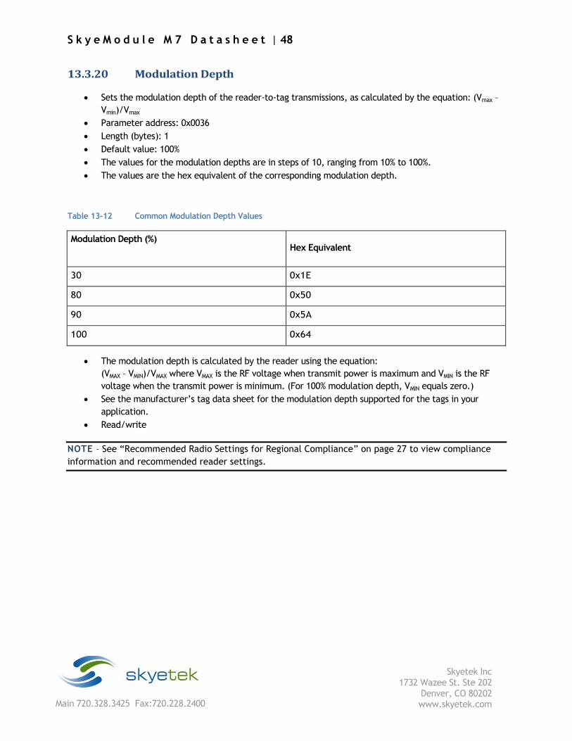
13.3.20 Modulation Depth
Sets the modulation depth of the reader-to-tag transmissions, as calculated by the equation: (Vmax –
Vmin)/Vmax
Parameter address: 0x0036
Length (bytes): 1
Default value: 100%
The values for the modulation depths are in steps of 10, ranging from 10% to 100%.
The values are the hex equivalent of the corresponding modulation depth.
Table 13-12 Common Modulation Depth Values
Modulation Depth (%) Hex Equivalent
30 0x1E
80 0x50
90 0x5A
100 0x64
The modulation depth is calculated by the reader using the equation:
(VMAX – VMIN)/VMAX where VMAX is the RF voltage when transmit power is maximum and VMIN is the RF
voltage when the transmit power is minimum. (For 100% modulation depth, VMIN equals zero.)
See the manufacturer’s tag data sheet for the modulation depth supported for the tags in your
application.
Read/write
NOTE – See “Recommended Radio Settings for Regional Compliance” on page 27 to view compliance
information and recommended reader settings.

S k y e M o d u l e M 7 D a t a s h e e t | 49
Skyetek Inc
1732 Wazee St. Ste 202 Denver, CO 80202 www.skyetek.com Main 720.328.3425 Fax:720.228.2400
13.3.21 Regulatory Mode
Enables pulse shaping, listen before talk, and timing modifications for regions with special regulatory
requirements, such as Europe.
Parameter address: 0x0037
Length (bytes): 1
Default value 0x00 (no pulse shaping)
Read/write
NOTE – See “Recommended Radio Settings for Regional Compliance” on page 27 to view compliance
information and recommended reader settings.
Table 13-13 Regulatory Mode Values
Mode Hex Value
No pulse shaping—FCC/North America 0x00
ETSI/Europea 0x01
a. Requires firmware version
S k y e M o d u l e M 7 D a t a s h e e t | 50
Skyetek Inc
1732 Wazee St. Ste 202 Denver, CO 80202 www.skyetek.com Main 720.328.3425 Fax:720.228.2400
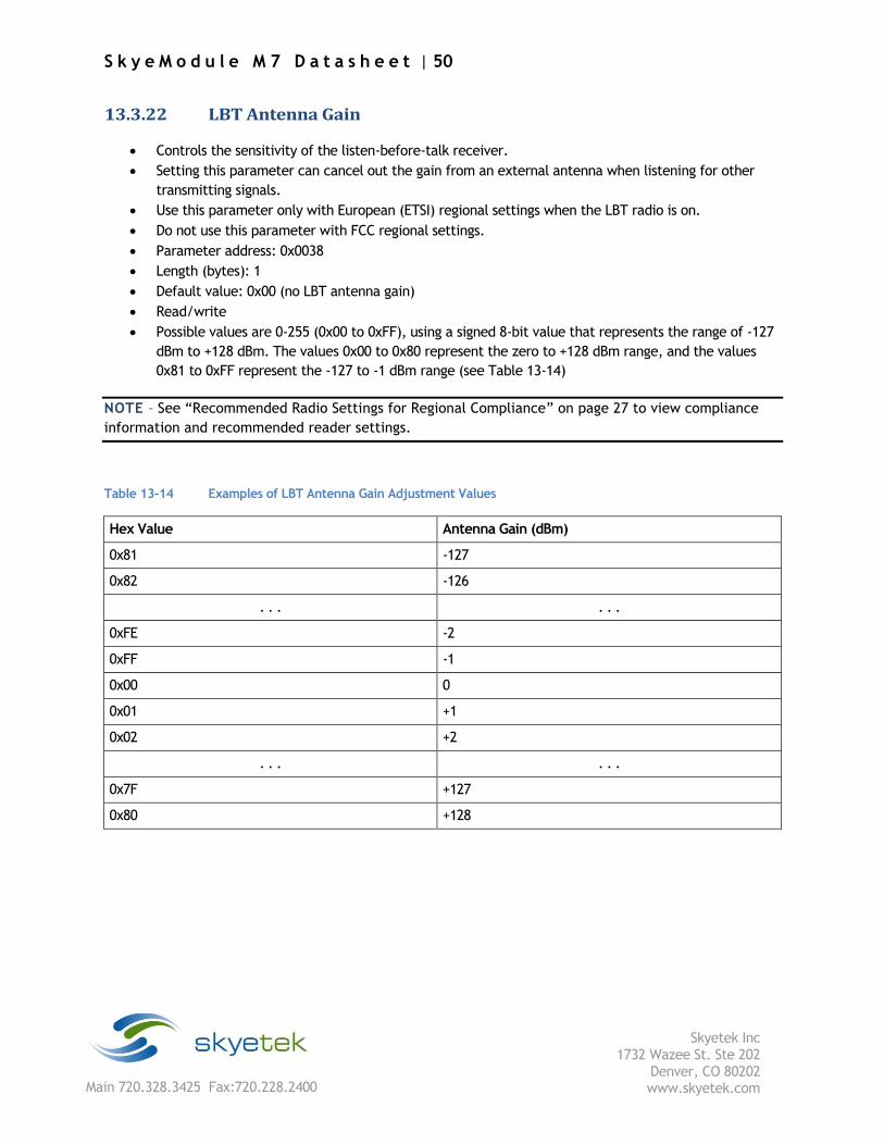
13.3.22 LBT Antenna Gain
Controls the sensitivity of the listen-before-talk receiver.
Setting this parameter can cancel out the gain from an external antenna when listening for other
transmitting signals.
Use this parameter only with European (ETSI) regional settings when the LBT radio is on.
Do not use this parameter with FCC regional settings.
Parameter address: 0x0038
Length (bytes): 1
Default value: 0x00 (no LBT antenna gain)
Read/write
Possible values are 0-255 (0x00 to 0xFF), using a signed 8-bit value that represents the range of -127
dBm to +128 dBm. The values 0x00 to 0x80 represent the zero to +128 dBm range, and the values
0x81 to 0xFF represent the -127 to -1 dBm range (see Table 13-14)
NOTE – See “Recommended Radio Settings for Regional Compliance” on page 27 to view compliance
information and recommended reader settings.
Table 13-14 Examples of LBT Antenna Gain Adjustment Values
Hex Value Antenna Gain (dBm)
0x81 -127
0x82 -126
. . . . . .
0xFE -2
0xFF -1
0x00 0
0x01 +1
0x02 +2
. . . . . .
0x7F +127
0x80 +128