SKT05 SKT05L - dwsitepro.com SKT05 SKT05L IMPORTANTE: Leer antes de usar IMPORTANT Lire avant usage...
24
Toll Free: (855) 354-9881 www.SitePro.us.com Operating / Safety Instructions Consignes de fonctionnement / sécurité Instrucciones de funcionamiento y seguridad model SKT05 SKT05L IMPORTANTE: Leer antes de usar IMPORTANT Lire avant usage IMPORTANT: Read Before Using
Transcript of SKT05 SKT05L - dwsitepro.com SKT05 SKT05L IMPORTANTE: Leer antes de usar IMPORTANT Lire avant usage...
Toll Free: (855) 354-9881 www.SitePro.us.com
Operating / Safety Instructions
Consignes de fonctionnement / sécurité
Instrucciones de funcionamiento y seguridad
model SKT05SKT05L
IMPORTANTE:Leer antes de usar
IMPORTANT Lire avant usage
IMPORTANT:Read Before Using
2
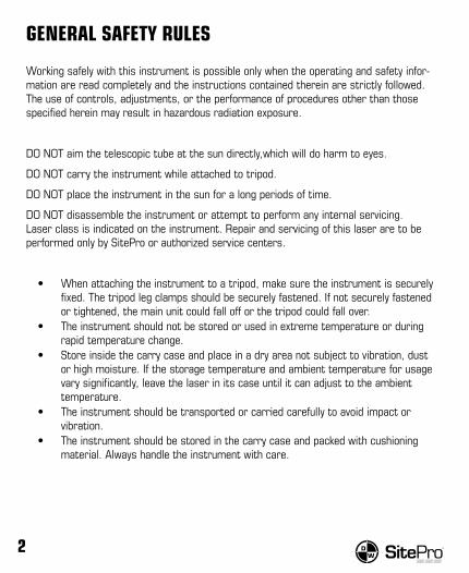
GENERAL SAFETY RULES
Working safely with this instrument is possible only when the operating and safety infor-mation are read completely and the instructions contained therein are strictly followed. The use of controls, adjustments, or the performance of procedures other than those specified herein may result in hazardous radiation exposure.
DO NOT aim the telescopic tube at the sun directly,which will do harm to eyes.
DO NOT carry the instrument while attached to tripod.
DO NOT place the instrument in the sun for a long periods of time.
DO NOT disassemble the instrument or attempt to perform any internal servicing. Laser class is indicated on the instrument. Repair and servicing of this laser are to be performed only by SitePro or authorized service centers.
• When attaching the instrument to a tripod, make sure the instrument is securely fixed. The tripod leg clamps should be securely fastened. If not securely fastened or tightened, the main unit could fall off or the tripod could fall over.
• The instrument should not be stored or used in extreme temperature or during rapid temperature change.
• Store inside the carry case and place in a dry area not subject to vibration, dust or high moisture. If the storage temperature and ambient temperature for usage vary significantly, leave the laser in its case until it can adjust to the ambient temperature.
• The instrument should be transported or carried carefully to avoid impact or vibration.
• The instrument should be stored in the carry case and packed with cushioning material. Always handle the instrument with care.

www.SitePro.us.com 3
1
9
10
8
5
6
7
3
2
4
11
SKT05 Only
FEATURES1. Handle2. Objective Lens3. Collimator4. Vertical Adjustment Knob5. Horizontal Adjustment Knob6. Focus Knob7. Eyepiece Lens8. Battery Compartment9. Display10. Instrument Leveling Screws11. Optical Plummet (SKT05)

4
Display Icon Description
% Vertical angle gradient percentage
Angle unit (GON)
Battery capacity
Slope distance
Horizontal distance
Height difference
Distance unit (meter)
distance unit(foot)
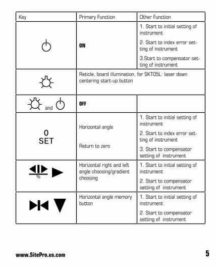
DISPLAY SYMBOLS AND KEY FUNCTIONS
www.SitePro.us.com 5
Key Primary Function Other Function
ON
1. Start to initial setting of instrument
2. Start to index error set-ting of instrument
3.Start to compensator set-ting of instrument
Reticle, board illumination, for SKT05L: laser down centering start-up button
and OFF
Horizontal angle
Return to zero
1. Start to initial setting of instrument
2. Start to index error set-ting of instrument
3. Start to compensator setting of instrument
Horizontal right and left angle choosing/gradient choosing
1. Start to initial setting of instrument
2. Start to compensator setting of instrument
Horizontal angle memory button
1. Start to initial setting of instrument
2. Start to compensator setting of instrument

6
INITIAL SETTINGThe instrument has many functions. In order to be appropriate to different observation,
please do initial setting before observation.
SETTING ITEMS
Unit of angle setting: °(degree) ‘ (cent) “(second)
(360 degrees one circle)
GON (400G one circle)
mil (6400mil one circle)
Factory setting ° ‘ “
Vertical angle “0” way setting:
horizontal: 0 degree (zenith distance :90 degree)
zenith distance: 0 degree (horizontal: 90 degree)
factory setting: zenith distance: 0 degree
Power auto off function: 30 min or deactivate
Factory setting: 30 mins
Minimum unit of angle displayed: 1” or 5”
Factory setting: 1”
Vertical index zero compensation setting:
Auto compensation or uncompensated
Factory setting: Auto compensation
Horizontal angle reading passes through 0°, 90°m, 180°, 270°, with audible ON or OFF
Factory setting: No beeps

www.SitePro.us.com 7
SETTING METHODPress key to turn power on and hold it until all the symbols displayed,then loose the
key. After three beeps, loose the key. The instrument will be into initial setting mode.
Press key to move the cursor to the next figure.
Press key to change the figure.
When all the initial setting is finished, press [0SET] key to come back to measurement mode.
Steps as follows:
1. Press key to turn power on,entering into initial setting status.
2. Buzzer prompt of horizontal angle position:
• ‘NO BEEP’ - no buzzer prompt in horizontal angle, Press key and for choosing
• ‘90 BEEP’ - the horizontal angle is close to 0°, 90°, 180°, 270°, buzzer sound.
3. Unit of angle, Press key and for page turning.
• ‘UNITA’ 360° • ‘UNITB’ 400G• ‘UNITC’ 6400mil
4. Vertical angle “0” position, Press key and for page turning.
• ‘ZEN=0’ zenith angle is 0°• ‘ZEN=90’ zenith angle is 90°
5. Auto power off time, Press key and for page turning.
• ‘NO OFF’ non auto power off• ‘30 OFF’ auto power off after 30 mins without any pressing

8
6. Minimum unit of angle displayed, Press key and key for page turning.
• ‘DSP 1’ mini display 1”• ‘DSP 5’ mini display 5”
7. Vertical compensator setting, Press key and key for page turning.
• ‘VTILT ON’ turn on compensator • ‘VTILT OFF’ turn off compensator
8 . When the initial setting is finished, the key must be pressed to confirm and save the setting. Otherwise, the setting will be the former setting before.
PREPARATION FOR SURVEYINGBATTERYThis series electrical theodolite adopt rechargeable lithium battery, The battery is 3.7v,1400mAh.
Insert and remove battery
Turn off power,press the top button of battery box and then remove battery.Insert the battery box into the groove and then press the top button of battery.
Battery message
Fully recharged new battery can be used 15 to 20 hours continuously. Right down message display consumption message. Each segment indicates about four hour’s consumption energy.
• and indicate that battery level is abundant.• indicates that the battery can be used only about two hours. Recharge the battery
or replace with a recharged battery.• When flickers then disappears indicates the battery level is low and. The
instrument only can be used approximately 20 minutes. Stop operating and change the battery as soon as possible.
www.SitePro.us.com 9
Battery recharging
• Battery should be recharged with the special charger. Insert the battery charger into the power source with 220V or 110V, remove the on-board battery from the main body, and connect the plug of the charger to the charging connector on the battery. The indicating red lamp is on that indicates the battery is been recharging and recharge will be completed after green lamp indicated. Then remove the plug from the charging connector.
SETUP INSTRUMENT• Adjust the tripod legs to obtain a suitable height. • Make sure the surveyed point is under the centering hole of tripod head.• Level the tripod head and lock.• Put the instrument on the tripod head and lock with the screws.
LEVELINGLevel the instrument with circular vial
• Turn B and C to let the bubble move to centre line.• Turn knob A to let bubble stay at center of circular vial.
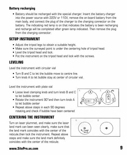
Level the instrument with plate vial
• Loose level clamping knob and turn knob B and C to let bubble center.
• Rotate the instrument 90°and then turn knob A to let bubble center
• Repeat above steps in each 90 degrees rotating,and check if bubble have been centered
CENTERING THE INSTRUMENTTurn on laser plummet, and make sure the laser land mark can been seen clearly, make sure that the land mark coincides with the center of the reticule,then lock the instrument. Repeat above steps and make sure the land mark definitely coincides with the center of the reticule.

10
POWER ON INSTRUMENT
To turn power ON, Press red key and hold it until all the symbols are displayed. The power is on.
SIGHT TARGETTurn telescope to bright background,turn eyepiece knob until reticle can been seen clearly.
• Use coarse sighting device to sight target.• Rotate vertical and horizontal brake knob and focus knob of telescope until target
can be seen clearly.• Rotate vertical and horizontal fine knob until center of reticle precisely aim at
target.• Eliminate parallax. View the target in up and down,left and right position through
scope. If there is relative displacement between target and both cross line images, rotate telescope focus knob until both images relative rest and can be seen clearly.
ANGLE MEASUREMENTNORMAL/REVERSED POSITION TELESCOPE“Normal position telescope” means that the shaft disc is on the left side of the telescope when observers face eyepiece lens. “Reversed position telescope” means that the shaft disc is on the right side of the telescope when observers face eyepiece lens.
Averaging the value of normal/reversed position can effectively eliminate the instrument systematic errors. So when measure angle,please rotate telescope 180° and observe with reversed position telescope after observing with normal position telescope.
HORIzONTAL ANGLE “0” SETTING
Sight the telescope at object A, press , set the horizontal angle reading as 0°00’00”.
Note: The key is valid only for horizontal angle. Horizontal angle can be set to 0 at any time except when key is locked.

www.SitePro.us.com 11
HORIzONTAL AND VERTICAL ANGLE MEASUREMENTSet the mode for horizontal right, Press to change horizontal angle from right to left mode.
• If display left,turn the alidade at clockwise to add horizontal angle.• If display left,turn the alidade at counterclockwise to add horizontal angle.
Choosing left and right measuring style are decided by observers preference.
Vertical angle measurement setting
There are two way of measuring vertical angle: zenith 0 degree and 90 degrees
Measurement
Sight target 1 with cross line centered
Press , horizontal angle setting of target 1 is 0°00’00”
Turning clockwise, sight target 2 with cross line center, horizontal angle between target 1 and 2 (turning right) will be displayed.
Example:
Press
Sight Target 1
Vertical angle of target 1 (zenith distance)
Horizontal angle of target 1 has been set to 0
Choose the direction of the horizontal angle measurement, sight target 2
Vertical angle of target 2 (zenith distance)
Horizontal angle, right turning directiontarget 1 has been set to 0

12
Press , choose right, turn telescope at counterclockwise, then sight target 1 with cross line center. Press ,horizontal angle of Target 1 turn to be “0” position, then sight target 2 with cross line center,display horizontal angle between 1 and 2 (turning left).
Rotate telescope 180 degree, repeat steps.
Horizontal angle lock and release
In the procedure of horizontal angle observation, if you want to retain the measured value,press .“left, right, horizontal” characters flicker at lower left of the display and the horizontal angle value will not change even if you rotate the instrument when you sight at any direction.
Press again to release lock function.
Note: lock and release of is only valid for horizontal angle.
Horizontal angle quadrant setting
Sight at the first object and then press to set the horizontal angle to zero. Turn the instrument around the vertical axis until the beep starts, displaying
.
Lock the instrument by the clamp screw and set the horizontal angle to 90° 00’ 00” by the tangent screw. Then, fix the quadrant target direction by the telescope reticule.
Repeat to setting quadrant target point of 180°, 270°. The buzzer beeps when the read-ing passes any of 0°, 90°, 180°, 270°.
Note: The beep can be canceled when we do initial setting.

www.SitePro.us.com 13
Vertical angle “0” setting
In initial setting, vertical“0”setting is zenith 0°/horizontal 0°.
ZEN=0 (zenith 0°) ZEN=90 (zenith 90°)
Measurement of zenith distance and vertical angle
zenith Distance If vertical angle is 0° for zenith direction, the vertical angle measured in this way is the zenith distance.
Zenith (0° 00’ 00”)
Horizontal direction (90° 00’ 00”)
Zenith distance: Q = (L+360°-R) /2Index difference: I = (L+R-360°) /2
Target 1
Q

14
Vertical Angle
If vertical angle is 0° in horizontal direction, then, the vertical angle measured in this way is the perpendicular angle.
Note: If index difference ‘I’ ≥ 10”, adjustment should be made as 8.6.
Gradient percentage
The vertical angle can be converted into gradient percentage in angle measurement mode.
The range of gradient is from horizontal direction to ±45° (except 45°). Otherwise the instrument will not display the grade percentage.
Method: Press until two beeps, the display panel shows vertical angle or gradient percentage alternately.
Zenith (90° 00’ 00”)
Horizontal direction (00° 00’ 00”)
Vertical Angle: Q = (L+180°-R) /2Index difference: I = (L+R-180°) /2
or I = (L+R-540°) /2
Target 1
Q
Gradient percentage value = tg a * 100%= H/D * 100%
H
S
D
a
www.SitePro.us.com 15
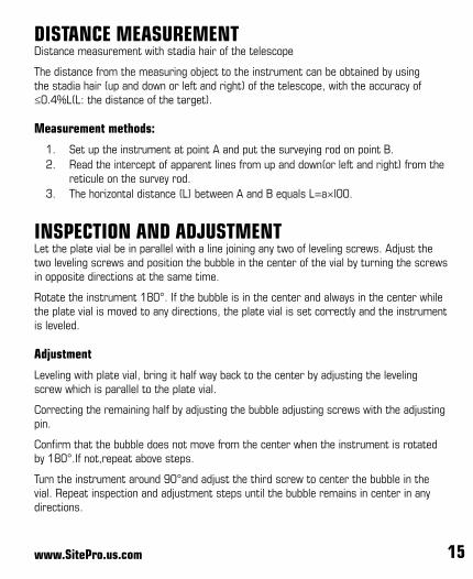
DISTANCE MEASUREMENT Distance measurement with stadia hair of the telescope
The distance from the measuring object to the instrument can be obtained by using the stadia hair (up and down or left and right) of the telescope, with the accuracy of ≤0.4%L(L: the distance of the target).
Measurement methods:
1. Set up the instrument at point A and put the surveying rod on point B.2. Read the intercept of apparent lines from up and down(or left and right) from the
reticule on the survey rod.3. The horizontal distance (L) between A and B equals L=a×l00.
INSPECTION AND ADJUSTMENTLet the plate vial be in parallel with a line joining any two of leveling screws. Adjust the two leveling screws and position the bubble in the center of the vial by turning the screws in opposite directions at the same time.
Rotate the instrument 180°. If the bubble is in the center and always in the center while the plate vial is moved to any directions, the plate vial is set correctly and the instrument is leveled.
Adjustment
Leveling with plate vial, bring it half way back to the center by adjusting the leveling screw which is parallel to the plate vial.
Correcting the remaining half by adjusting the bubble adjusting screws with the adjusting pin.
Confirm that the bubble does not move from the center when the instrument is rotated by 180°.If not,repeat above steps.
Turn the instrument around 90°and adjust the third screw to center the bubble in the vial. Repeat inspection and adjustment steps until the bubble remains in center in any directions.
16
Circular vial
Ajustment is unnecessary if the bubble of the circular vial is in the center after inspection and adjustment of the plate vial. If not,it is necessary.
If the bubble of the circular vial is not in the center, bring the bubble to the center by us-ing adjusting pin or adjustable wrench to adjust the bubble adjusting screw.
When adjusting, first loosen the screw on the Opposite of the offset side, then, tighten the adjusting screw on the offset side, bring it to the center.
After the bubble stays in the center, keep the fastening strength of the three screws in uniformity.
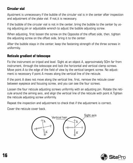
Reticule gradient of telescope
Fix the instrument on tripod and level. Sight at an object A, approximately 50m far from instrument, through the telescope and lock the horizontal and vertical clamp screws.Move point A to the edge of the field of view by the vertical tangent screw. No adjust-ment is necessary if point A moves along the vertical line of the reticule.
If the point A does not move along the vertical line, first, remove the reticule cover between eyepiece and focusing screw, and you can see the four screws.
Loosen the four reticule adjusting screws uniformly with an adjusting pin. Rotate the reti-cule around the aiming axis, and align the vertical line of the reticule with point A.Tighten the reticule adjusting screw uniformly.
Repeat the inspection and adjustment to check that if the adjustment is correct.
Cover the reticule cover back.
A
Sight axisVertical hair
A’
A
A’

www.SitePro.us.com 17
Perpendicularity of aiming axis to horizontal axis(2C)
Fix the instrument on tripod and level. Sight at the object A in normal position (left or right ways turning are all acceptable,just keep in same way during inspecting,and please not press ) and read the horizontal angle left1.
Loosen vertical and horizontal clamp screws, and reverse the telescope. Sight at the object A in reversed position and read the horizontal angle value left2
So: 2C = left1-(left2 180°)
If |2C| < 16”, needless to adjust.
If |2C| ≥ 16”, need to adjust.
In the inverted position rotate flat mirror micro hand wheel so that the inverted mirror reading
Left2 = left2+C
Take down the cover of the reticule. Adjust the two adjusting screws by loosening one and tightening the other. Move the reticule to sight at the object A exactly.
Repeat inspection and adjustment until | 2C | <16”. Cover the cover of reticule back.
Vertical index zero compensation
The instrument with vertical disc which be equipped with auto compensation and zero-storing device,please make inspection as follows:
After precisely leveling the instrument,make the direction of telescope coincide with the line between center of instrument and screw of any tripod leg (setting as M),then tight the horizontal clamping knob.
Turn power on,sight at target A and tight the vertical clamping knob,then instrument will display the vertical angle.
Rotate the screw M slowly in one direction until it gets about 10mm and the instrument display “TILT”,it means the vertical incline has been out of compensation range.
Then rotate the screw M in the opposite direction,the instrument is operating smoothly if vertical angle is redisplayed,otherwise, the compensator is abnormal or failure.
The adjustment of the compensator is complicated, please send it to factory for repairing if it is abnormal or failure.

18
Vertical index difference and vertical index zeroing
Note:After making adjustments make the inspection as following:
Leveling the instrument and turn the power on. Then, sight at a reference A with normal position telescope and obtain the vertical angle (L).
Reverse the telescope and sight at the object A again and obtain the vertical angle (R).
• If vertical angle is zero at zenith, then, vertical index difference I = (L+R-360°) / 2• If vertical angle is zero at horizontal, then, I = (L+R-360°) / 2 or (L+R-540°) / 2.• If | I | ≥ l0”, vertical index zeroing should be set again.
After leveling the instrument, press + key and ,release when display charac-ters and release + until three beeps,The instrument displays:
In normal position, Sight at a clear and stable object A , which is nearly the same height as the instrument, turn the telescope around near the horizontal direction until vertical angle of A appears. Press key, displaying FACE-2.
Reverse the telescope and sight at the object A again. Press key to finish vertical index zeroing setting. The instrument returns to angle measurement mode.
Repeat the inspection procedure until index difference (I) meet the requirement, If the vertical index difference does not meet the standard yet after being adjusted repeatedly, the instrument should be sent to factory to be repaired.

www.SitePro.us.com 19
TECHNICAL DATA
Telescope
Image Erect
Magnification 30×
Objective Aperture 45mm
Resolving Power Electronic (±5º)
Field of View 1°30’
Shortest Focusing Distance 1m
Stadia Ratio 100
Resolving Power 3”
Angle Measure-ment
Angle Measurement Mode Absolute Angle Encoder System
Minimum count 1”, 5”
Mode of detection H:double-line V:double-line
Precision 5”
Measure-ment Unit DEG MIL GON
Display LCD two sides
CompensationInclination sensor Auto vertical compensation
Working range ±3’
Plummet SKT05: Optical; SKT05L: Laser
Precision of plate vial 30”/2mm
Precision of circular vial 8’/2mm
Working Temperature -25°C to +50°C
Instrument weight 11lb (5kg)
Volume 7.5” x 6.1” x 13.6” (190mm X 155mm X 345mm)

20
LASER PLUMMET (SKT05L)Press the twice to activate the laser plummet. To turn off the laser plummet, press
the twice.
ERROR MESSAGEDisplay TILT:
If vertical disc compensator out of range, re-level instrument. If no change, send the instrument to an authorized service dealer for repair/maintenance.
Note: the instrument can measure data even turn off compensator in initial status.
Instruction: if there are error messages, fully check instrument firstly and repeat steps in the instruction manual.

www.SitePro.us.com 21

22
WARRANTYLIMITED WARRANTY PROGRAMSitePro warrants the Digital Theodolite to the original purchaser for a period of two (2) years from date of purchase against any defects in material or workmanship. This war-ranty does not cover part failure due to normal wear or tool abuse. For more details of warranty coverage and warranty repair information, call (855) 354-9881. This warranty does not apply to accessories items or damage caused where repairs have been made or attempted by person other than SitePro or authorized service center. This warranty gives you specific legal rights and you may have other rights which vary in certain states or provinces.
This Limited Warranty does not apply to accessory items such as tripods, rods, poles, prisms, hand levels, field supplies, instrument accessories and other related items. These items receive a 90 day limited warranty.
To make a claim under this Limited Warranty, you must return the tool, transportation prepaid, along with any relevant paperwork (RGA number, if you have obtained one, proof of purchase, contact information, and any request for new accessories, etc.) to our Service Department or an Authorized Service Center.
SitePro/Service Department, 7619 S 1150 E, Otterbein, IN 47970
IMPLIED WARRANTIES ARE EXPRESSLY LIMITED IN DURATION TO ONE YEAR FROM DATE OF PURCHASE.
IN NO EVENT SHALL SELLER BE LIABLE FOR ANY INCIDENTAL OR CONSEQUENTIAL DAMAGES (INCLUDING BUT NOT LIMITED TO LIABILITY FOR LOSS OF PROFITS) ARIS-ING FROM THE SALE OR USE OF THIS PRODUCT. SOME STATES IN THE U.S., AND SOME CANADIAN PROVINCES DO NOT ALLOW THE EXCLUSION OR LIMITATION OF INCIDENTAL OR CONSEQUENTIAL DAMAGES, SO THE ABOVE LIMITATION MAY NOT APPLY TO YOU.
SOME STATES IN THE U.S. AND SOME CANADIAN PROVINCES DO NOT ALLOW LIMITATIONS ON HOW LONG AN IMPLIED WARRANTY LASTS, OR THE EXCLUSION OR LIMITATION OF SPECIAL, INCIDENTAL OR CONSEQUENTIAL DAMAGES, SO THESE LIMITATIONS AND EXCLUSIONS MAY NOT APPLY TO YOU. THIS WARRANTY GIVES YOU SPECIFIC LEGAL RIGHTS. YOU MAY ALSO HAVE OTHER RIGHTS WHICH VARY FROM STATE/PROVINCE TO STATE/PROVINCE.

www.SitePro.us.com 23

© Dave White’s SitePro, LLC
Otterbein, IN
UM-29SKT05 12/12 mQ Printed in China