SKP Engineering College -...
96
SKP Engineering College Tiruvannamalai – 606611 A Course Material on Railway, Airport and Harbor Engineering By R.Pakuththarivaalan Assistant Professor Civil Engineering Department Quality Certificate
-
Upload
doankhuong -
Category
Documents
-
view
217 -
download
0
Transcript of SKP Engineering College -...

S.K.P. Engineering College, Tiruvannamalai VI SEM
Civil Engineering Department 1 Railway, Airport and Harbor Engineering
SKP Engineering College
Tiruvannamalai – 606611
A Course Material
on
Railway, Airport and Harbor Engineering
By
R.Pakuththarivaalan
Assistant Professor
Civil Engineering Department
Quality Certificate

S.K.P. Engineering College, Tiruvannamalai VI SEM
Civil Engineering Department 2 Railway, Airport and Harbor Engineering
This is to Certify that the Electronic Study Material
Subject Code: CE6604
Subject Name: Railway, Airport and Harbor Engineering
Year/Sem: III / VI
Being prepared by me and it meets the knowledge requirement of the University
curriculum.
Signature of the Author
Name: R.Pakuththarivaalan
Designation: Assistant Professor
This is to certify that the course material being prepared by Mr. R.Pakuththarivaalan is
of the adequate quality. He has referred more than five books and one among them is
from abroad author.
Signature of HD Signature of the Principal
Name: A.Saravanan Name: Dr.V.Subramania Bharathi
Seal: Seal:

S.K.P. Engineering College, Tiruvannamalai VI SEM
Civil Engineering Department 3 Railway, Airport and Harbor Engineering
CE6604 Railway, Airport and Harbor Engineering L T P C 3 0 0 3
OBJECTIVES: To expose the students to Railway planning, design, construction and
maintenance and planning and design principles of Airports and Harbours. UNIT I RAILWAY PLANNING 10 Significance of Road, Rail, Air and Water transports - Coordination of all modes to achieve sustainability - Elements of permanent way –Rails, Sleepers, Ballast, rail fixtures and fastenings, - Track Stress, coning of wheels, creep in rails, defects in rails – Route alignment surveys, conventional and modern methods- - Soil suitability analysis - Geometric design of railways, gradient, super elevation, widening of gauge on curves- Points and Crossings. UNIT II RAILWAY CONSTRUCTION AND MAINTENANCE 9 Earthwork –Stabilization of track on poor soil –- Tunneling Methods, drainage and ventilation –-Calculation of Materials required for track laying - Construction and maintenance of tracks – Modern methods of construction & maintenance - Railway stations and yards and passenger amenities- Urban rail –Infrastructure for Metro, Mono and underground railways. UNIT III AIRPORT PLANNING Air transport characteristics-airport classification-air port planning: objectives, components, layout characteristics, socio-economic characteristics of the Catchment area, criteria for airport site selection and ICAO stipulations, Typical airport layouts, Case studies, Parking and circulation area. UNIT IV AIRPORT DESIGN 8 Runway Design: Orientation, Wind Rose Diagram - Runway length - Problems on basic and Actual Length, Geometric design of runways, Configuration and Pavement Design Principles – Elements of Taxiway Design –Airport Zones –Passenger Facilities and Services –Runway and Taxiway Markings and lighting. UNIT V HARBOUR ENGINEERING 10 Definition of Basic Terms: Harbor, Port, Satellite Port, Docks, Waves and Tides –Planning and Design of Harbours: Requirements, Classification, Location and Design Principles – Harbour Layout and Terminal Facilities –Coastal Structures: Piers, Break waters, Wharves, Jetties, Quays, Spring Fenders, Dolphins and Floating Landing Stage –Inland Water Transport –Wave action on Coastal Structures and Coastal Protection Works –Environmental concern of Port Operations – Coastal Regulation Zone, 2011.
TOTAL: 45 PERIODS

S.K.P. Engineering College, Tiruvannamalai VI SEM
Civil Engineering Department 4 Railway, Airport and Harbor Engineering
OUTCOMES: On completing the course, the students will have the ability to Plan and Design
various civil Engineering aspects of Railways, Airports and Harbour.
TEXT BOOKS: 1. Saxena Subhash C and Satyapal Arora, "A Course in Railway
Engineering", Dhanpat Rai and Sons, Delhi, 2003 2. Satish Chandra and Agarwal M.M, "Railway Engineering", 2
nd Edition,
Oxford University Press, New Delhi, 2013. 3. Khanna S K, Arora M G and Jain S S, "Airport Planning and Design",
Nemchand and Brothers, Roorkee, 2012. 4. Bindra S P, "A Course in Docks and Harbour Engineering", Dhanpat
Rai and Sons, New Delhi, 2013 REFERENCES: 1. Rangwala, "Railway Engineering", Charotar Publishing House, 2013. 2. Rangwala, "Airport Engineering", Charotar Publishing House, 2013. 3. Rangwala, "Harbor Engineering", Charotar Publishing House, 2013. 4. Oza.H.P. and Oza.G.H., “A courbourseinEngineering”Docks&Ha. Cha
Co., 2013 5. Mundrey J.S. “A course in Railway Track Engineering” 6. Srinivasan R. Harbour, “Dock and Tunnel Engineering", 26
th Edition 2013

S.K.P. Engineering College, Tiruvannamalai VI SEM
Civil Engineering Department 5 Railway, Airport and Harbor Engineering
CONTENTS
S.No Particulars Page
1 Unit – I 6
2 Unit – II 25
3 Unit – III 43
4 Unit – IV 58
5 Unit – V 79

S.K.P. Engineering College, Tiruvannamalai VI SEM
Civil Engineering Department 6 Railway, Airport and Harbor Engineering
UNIT 1
TWO MARKS QUESTIONS AND ANSWERS
1.What is meant by traffic survey
The main aim of the traffic survey is to submit the field data to the authority of the project. The traffic report submitted will be subjected to scrutiny to the engineer, Administration and financial levels.
2.Why a reconnaissance Should be conducted
From the preliminary data based on the existing survey maps and aerial photographs a few tentative alignments are conducted
For each preliminary data a reconnaissance survey is taken up with a minimum Expenditure and time Such that the important features are noted down
3.What are the instruments used in the preliminary Survey
1.Plane table 2. Dumpy level 3. Prismatic compass 4. Theodolite 5. Tachometer
4.What is a track. List the various components of the track
A complete track of the railway line at which trains run is commonly referred to as permanent way or simply a track
The components of a track are Sleepers, rails, fittings, Fastening, ballast and the formation
5. List the requirements of an ideal Rails
a) The rail section should be economical b) the center of gravity Should be at the middle height c) Balanced distribution of metal on the cross section d) Adequate Stability Against overturning e) Enough vertical and lateral stiffness
6.How a Section of the rail mentioned? What are the Standard section available on broad gauge in Indian railway
Rail section is designated by its weight per unit length. Section available on broad gauge are 60kg/m with a rail length of about 13.0 meter
7.What are the different types of joint used in rails
Two rails are connected by a joint which forms the weakest part of the track .Based on the position joints are classified into Square and Staggered Joints.
Based on the position of the Sleepers, rail joints are the three types. That are Suspended joint, Supported joint and Bridge Join

S.K.P. Engineering College, Tiruvannamalai VI SEM
Civil Engineering Department 7 Railway, Airport and Harbor Engineering
8.list the various effects of the creep 1. Buckling of the track 2. Change of the gap 3. Distortion of points and crossings 4. Difficulty in changing rails 5. Change of Sleeper position
9.List any three advantages and disadvantages of the Steel Sleepers
Advantages
1.Less and simple form of fastening 2. Comparatively large life 3.maintenance and adjustment
Disadvantages
1. High initial cost 2. Susceptible to corrosion 3. Not suitable for track circuited areas
10.What are the basic function of the ballast
1. Provide a level and hard bed 2. Sleeper are held in position 3. Drains the water immediately 4. Avoid the growth of vegetation 5. resists the displacement in all direction
11.Define Super-Elevation
Super- elevation or cant is the difference in height between the outer and inner rails in a
curve. This is provided in the field by a gradual lifting of the outer rails While maintaining the inner rail in its original level
12.What is meant by cant gradient
Can’t gradient expressescantinthethegiven lengthincreaseoftransition. Forof the Example a gradient of 1 in 1000 represents a cant of 1mm is in every 1000mm of the transition length.
13.What is an Ideal Alignment?
Alignment of the track line comprises of fixing the direction and position of the track in
the horizontal and vertical planes. An ideal alignment Should meet certain requirements Serves the basic purposes, form of the part of integrated development of the country, Economical in construction and maintenance, provide comfort and safety and have a scenic beauty

S.K.P. Engineering College, Tiruvannamalai VI SEM
Civil Engineering Department 8 Railway, Airport and Harbor Engineering
16 MARKS QUESTIONS AND ANSWERS 1. What is meant by gradient and enumerate the various types of gradient with all
the details
Any departure of the track from the level is known gradient or gradient. Reason for the
usage in railway track 1.To provide a uniform rate of rise or fall as far as possible 2.To reach the various stations located at different elevation 3. To reduce the cost of the earthwork.
Types of gradient
1.Ruling gradient 2.Momentum gradient 3.Pusher or helper gradient 4.Gradient at Station Yard
1.Ruling gradient
The ruling gradient on a section may be defined as a gradient which determines
the maximum load that the engine can haul on the section
In determination the ruling of the section may be defined as, it will not only be that the survey of the gradient that will come into pla position
In plain terrain = 1 in 150 to 1 in 200 In hilly terrain = 1 in 100 to 1 in 150
2. Momentum gradient
The rising gradient is called as momentum gradient and in such cases a steeper grade
than the ruling grade can be adopted The gradient on the section Which through more severe than the ruling gradient, do not
determine the maximum load of the terrain but on account of their favorable position on the track
For example in valleys, a falling gradient is usually followed by a rising gradient 3. Pusher or helper gradient
If the grade concentrated in a Specific section such as mountainous section. Instead of limiting the terrain load,
It may operationally easy or even economical to run the terrain on the basis of load that can carry in the remaining portion of the track and arrange for an assisting engine is called pusher or helper gradient
4. Gradient in Station Yard
The gradient at Station Yard have to be sufficiently low due to the following reason
(a) To prevent the movement of Standing vehicle on the track due to the effect of the gravity
(b) To prevent the additional resistance due to the grade on the Standing Vehicle

S.K.P. Engineering College, Tiruvannamalai VI SEM
Civil Engineering Department 9 Railway, Airport and Harbor Engineering
Grade Compensation
In order to avoid the resistance beyond the allowable limit, the gradients are
reduced on curves. Then the reduction can be named as Grade compensation
2. Enumerate the concept of an grade compensation and also explain the basic
formulas used in grade compensation
Due to the rigidity of the Wheel base, it is sometimes found on the Curve that
the rails are tilled outwards so that the actual gauge in more than the theoretical value Wheel Base is defines as the distance between the adjoining Axes which are
held in a rigid frames The maximum value of the rigid wheel base in India on B.G Yard and M.G yard
are 610cm and 48 cm respectively To prevent the tendency the gauge of the track is sometimes widened on
Sharpe Curves. The amount of widening of gauges depending upon the radius of the Curve, Gauge and rigid Wheel base on the vehicle
The various formulas are Available for finding out the Extra Width of the gauge required on Curves. Incase, the Extra width Should not Exceed 25mm on 1676mm and 1435mm gauges and 16mm on the M.G. Some rules are mentioned as follows
Rule 1.
D = (B+L2
)*125 / R
Where D= Extra width of the gauge in mm B=Rigid Wheel base in mm L=Lap of the Curve R=Radius of the Curve
Now, the value of lap of flange in mm is obtained by the Following equation
L = 2 [(D+H)*h] ½
Where D= Diameter of the Wheels in mm H=Depth of the Wheel flange below in mm
Rule 2.
Multiple half of the Wheel base by lap of the flange and when divide this result
by the radius of the curvature plus half the gauge Multiple the gradient by 3000 and the result will be the Extra required in mm. The
Wheel base, lab of flange, radius of the curvature and the gauge to be Expressed in meters
Rule 3.
The gauge was widened for a curve of over 3 degrees. But at present the Gauge

S.K.P. Engineering College, Tiruvannamalai VI SEM
Civil Engineering Department 10 Railway, Airport and Harbor Engineering
is not widened up to the curvature of 4.5 degree on the B.G Yard and 5-9 to on M.G in USA the practice is not to widen the gauge at the rate of 3mm for every 2 degrees of curvature up to a maximum of 19m
3. What is meant by permanent way. Explain the basic requirements of an permanent way
The finished completed track of a railway line is commonly known as an
permanent way. It is essentially consisting of the following three points
That are 1.Rails 2.Sleepers 3.Ballast
The gauge of the track Should be uniform and there Should not be varying gauges.
There Should be minimum friction between the Wheel of rolling Stocks and the rails The gradient provided on the permanent way Should be even and uniform. The
design of a permanent way Should be such that the load of the terrain is uniformly distributed over it.
The precautions Should be taken to avoid the occurrences of creep. The rail joint Should be properly designed and maintained
The alignment of the track Should be free from kinks or irregularities. The Special attention Should be given on the design of permanent way on curves
It Should possess Sufficient lateral rigidity and vertical Stiffness. The overall Construction of the permanent way Should be Such that it requires minimum of maintenance
Requirements of an Ideal Permanent Way

S.K.P. Engineering College, Tiruvannamalai VI SEM
Civil Engineering Department 11 Railway, Airport and Harbor Engineering
1. The gauge Should be correct and uniform
2. The alignment Should be correct and it Should be free from kinks and irregularities
3. The radii and super elevation and curves Should be properly designed and maintained
4. Drainage System must be performed for enhancing Safety and durability of the
track
5. The various components of the track.,i.e the rails,fittings,Sleepers,Ballast and
formation must be fully satisfy the requirements for Which they have been provided
6. There Should be adequate provision for easy renewals and replacement
7. The track Structure Should be Strong, low initial cost as well as maintenance cost
8. The rail Should be in proper level. In a Straight track ,two rails are must be at the
same level.
9. The outer rails should be proper transition at the junction of a straight and a curve
4. What is meant by joints in rails. Explain the various types of joints in railway
Rail joints are necessary to hold together the adjoining ends of the rails
in the correct position, both in the horizontal and vertical planes. The Strength of the rail joint is only 50% of the Strength of the rail
Requirement of an Ideal Joint
An ideal or perfect rail Joints is the one Which provides the Same Strength
and the Stiffness as the rail Section of the Track The rail Joint Should be provide Enough Space for Expansion and the Contraction
to the Account for the effect of the temperature variables It Should not allow the rails ends to get battered in any case. The rail joint Should
be as Strong and Stiff as the rail Itself Types of joints
1.Supported rail joint 2.Suspended rail joint 3.Bridge joint 4.Welded rail joint 5.Staggered or Broken rail joint 6.Square or Even joint 7.Base joint 8.Compromise joint 9.Insulating joint 10.Expansion

S.K.P. Engineering College, Tiruvannamalai VI SEM
Civil Engineering Department 12 Railway, Airport and Harbor Engineering
joint 1.Supported rail joint
The rail ends rest on the single Sleeper is called joint Sleeper and it is also called Supported joint. these Sleepers are Supported with a long fish plate. i.e. combined and Suspended joint is most commonly objectionable
Undue load comes on central Sleepers and in turn the loose Central Sleepers converts this joint into a weak Joint
2.Suspended rail joint
When rail ends are projected beyond Sleepers may be called Should
Sleepers. It is termed as suspended. The type of joint is generally used timber and Steel rough Sleeper on Indian and foreign railways
3.Bridge joint
When a rail ends are projected beyond as in case Suspended joint and they are
connected by a flat or corrugated plate is calle
4.Welded rail joint
These are the best joints as they fulfill nearly all the requirement of
an ideal or perfect joint and it will be discussed in next articles 5.Staggered or Broken rail joint
In this position of joints on railway on railw this type of joint, the joints on railways track are not directly opposite to the joint of the other rail tracks. this the required definition for the term Broken rail joint

S.K.P. Engineering College, Tiruvannamalai VI SEM
Civil Engineering Department 13 Railway, Airport and Harbor Engineering
6.Square or Even joint
In this also the position of the railway trac joint of one rail track are directly
opposite to the joint in the other railway track. This types are generally used on Straight lines
7.Base joint
In this similar to the Bridge joint with the difference that inner fish plate
are of bar type and the other fish plate are of the Special angle types, due to the complication these are not commonly used
8.Compromise joint
Two different rail section are required be joined together, it is done by

S.K.P. Engineering College, Tiruvannamalai VI SEM
Civil Engineering Department 14 Railway, Airport and Harbor Engineering
means of fishplate and it is joint termed as compromise joints 9.Insulating joint
When insulating medium is inserted in a rail joint to Stop the flow of current
beyond the track circuited part is called insulated join
5. A 5° curve diverges from a 3° main curve in reverse direction in the layout of B.G Yard. If the Speed on the branch line is restricted 35KMPH .determine the restricted Speed on the main Curve Given Data
V = 35kmph Step 1: To find Equilibrium Super-Elevation 2
e GV
1.27R
Where
V= 35 KMPH
G=1.676 for B.G Yard
R= 1720 5
Then We can get
e = 1.676* 35* 35 * 5
1.27 1720
e = 4.71 cm
Step2: To find the negative Can’t
= equilibrium cant –can’t deficiency
= (4.71 –7.60 ) cm
= 2.89 cm
Note
Can’t deficiency= 7.60 (for B.G Yards)
Step3: To find negative can’t
Negative can’t= maximum-elevation onpermissiblethemainline Super

S.K.P. Engineering College, Tiruvannamalai VI SEM
Civil Engineering Department 15 Railway, Airport and Harbor Engineering
= 2.89 cm
Step 4: To find theoretical Super-elevation
Theoretical Super-elevation Provided on the main line
= 2.89+7.60 cm =10.49 cm
Step 5: To find the Speed on the main line
e = 1.676*V
2 * 3
1.27
1720
10.49=
1.676*V 2
*
3
1.27 1720
V2
=4550 KMPH
V= 67.40 KMPH
6. If A 8° curved track diverges from a main track of 5° in an opposite direction in the layout of B.G Yard. Calculate the Super-elevation and Speed of a branch line. If the maximum Speed permitted on the main line is 45 KMPH Given Data
V = 45KMPH Step 1: To find Equilibrium Super-Elevation
e
Where
GV2
1.27R
V= 45 KMPH G=1.676 for B.G Yard
R= 1720 5 Then We can get
e = 1.676* 45* 45 * 5
1.27 1720
e = 7.78 cm

S.K.P. Engineering College, Tiruvannamalai VI SEM
Civil Engineering Department 16 Railway, Airport and Harbor Engineering
Step2: To find the negative Can’t
= equilibrium cant –can’t deficiency = (7.78 –7.60 ) cm
= 0.18 cm
Note
Can’t deficiency= 7.60 (for B.G
Step3: To findnegative can’t
Negative can’t = -elevationmaximumonpermissiblethemainline Super = - 0.18 cm Step 4: To find theoretical Super-elevation
Theoretical Super-elevation Provided on the main line = -0.18+7.60 cm =7.42 cm
Step 5: To find the Speed on the main line
e = 1.676*V 2 * 8
1.27 1720
7.12= 1.676*V 2 * 8
1.27 1720
V2
=1210 KMPH
V= 34.70 KMPH
7. Explain the various types of conventional and modern methods of Survey used in
railway. Give all in detail
(1)Surveys for track alignments
The entire survey work to be conducted may be divided into the following parts:
1) Traffic survey 2) Reconnaissance survey 3) Preliminary survey 4) Location survey 5) Modern methods survey
Traffic survey
The main aim of traffic survey is to submit the field data to the authority judge the suitability of the project.

S.K.P. Engineering College, Tiruvannamalai VI SEM
Civil Engineering Department 17 Railway, Airport and Harbor Engineering
1) Particulars of villages and towns within about 20km from the proposed track
along with the population. 2) Location of existing industries and the potential growth of them. 3) Volume of traffic in terms of passengers and goods wagons. 4) Availability of export based natural resources like, iron, coal, etc.
Reconnaissance survey
Reconnaissance survey should furnish the following details:
1) Topographical features of the area. 2) Existing water resources along with their discharge details . 3) Natural features like ridges, valley, forest, etc. 4) Geographical and soil classification.
Preliminary survey:
Steps involved in this survey:
1) Construction pillar is erected to mark the starting point. 2) A fly leveling is done to connect the starting point and a nearby GTS beach mark.
3) A compass survey is conducted along the alignment to prepare a route survey map
covering about 100m on either side of the alignment. 4) A cross sectional leveling is done at regular intervals say 100m.
From the field data collected as described in the above steps the following
drawings prepares:
1) Longitudinal section 2) Typical cross section 3) Profile of crossings with rivers, streams, canals, and rails roads crossings. 4) Maximum and minimum width of track.
With the maximum required drawings, a comparative statement bringing
out the following details are prepared:
1) Length of the track 2) Gradient details both ruling and maximum 3) Sub grade and formation cost 4) General details
Location survey
The transfer is done by adopting the following steps:
1) 15cm pegs at 30m intervals are driven 2) Every tenth peg is marked by 60cm pegs

S.K.P. Engineering College, Tiruvannamalai VI SEM
Civil Engineering Department 18 Railway, Airport and Harbor Engineering
3) Pegs are also driven to demarcate the center line of the track 4) At every km length masonry pillars are constructed which serve as bench marks.
Modern surveying instruments and methods:
Some of these survey aids and techniques are the following:
1) Remote sensing data 2) Aerial photographs 3) Electro - magnetic distance measurement 4) Digital terrain modeling 5) Geographic information system
Remote sensing data
Remote sensing data or satellite imaginary pr Indian space research organization(ISRO) provides such maps which are up dated once a month.
Ground conditioned can be well defined with a combination of satellite images and topographical maps. Using these the best corridor is chosen for further analysis. Satellite data maps are of immense use wherein no adequate data could be got from topography.
Aerial photographs
Aerial photogrammetric is that type of photography wherein the photographs are
taken by cameras mounted on an aircraft lying over the area. Stereo photographs are taken is another system which is another system which is a recent development. In this system photographs are taken in pairs at the ends of a base line of known length and direction.
Aerial photographs of the entire country are taken once in every 3 to 5 years which
are available with survey of India. These photographs are further used to develop details of the chosen corridor. The photographs are very useful to find tunnel locations stations sites, and identify correctly the river crossings, etc.
Electro magnetic distance measurements (EDM)
Electro magnetic distance measurements is a general term used collectively in the
measurements of distance applying electronic methods. Depending on the type of carrier wave used, EDM instruments may be classified as (1)microwave instruments (2)visible light instruments and (3)infrared instruments.
These instruments are very light and compact and can mounted with theodolite. Thus these instruments enable to measure angles and distances simultaneously.
Digital terrain modeling(DTM)
Digital terrain modeling is a computer aided design. Using such models the most
economical alignment may be obtained. After the alignment decision, ground stations are fixed in the form of mutually visible points.

S.K.P. Engineering College, Tiruvannamalai VI SEM
Civil Engineering Department 19 Railway, Airport and Harbor Engineering
All the other details, for the preliminary survey can be worked out with the help of
contours maps, photogrammetric plotted sheets and other computer aids. Geographical information system (GIS)
GIS is new technology which covers a number of fields such as remote
sensing, cartography, surveying and photography. 8. Enumerate the various types of rail sections used in railway. Give all in details
Rails are the prime members of the permanent way which are laid in two parallel lines to
provides a continuous, level surface for the movement of train. In order to withstand the stresses they are made of high carbon steel.
Functions of rails :
1) Basically it is to provide a continuous and smooth surface with an acceptable gradient
for the movement of trains.
2) Rails to bear the stresses developed due to heavy vertical loads, stresses due to lateral thrust, breaking stresses and thermal stresses.
Types of rails:
In general a rail section should be such that every part of the material is stressed to the maximum allowable stresses. Such a section only will ensure an economical section.

S.K.P. Engineering College, Tiruvannamalai VI SEM
Civil Engineering Department 20 Railway, Airport and Harbor Engineering
Double headed(DH) rail sections were the first rails used. It was felt that once one head
wooden out the other one could e used. However it was found that due to the impact of the wheels lower surface in contact with the chairs got dented. This lead to the development of bull headed rail which had one head larger than the other. This was found to have a serious drawback that chairs were required for fixing the rails to the sleepers.
Thus a flat-footed (FF) rail with an inverted T-type was developed. This type could be
fixed directly to the sleepers with the help of spikes. This type of rail is adopted all over the world. Compared to BH-type, the flat footed rails have the following advantages:
1)provides better rigidity and stiffness to resist vertical and lateral forces. 2) points and crossings are simpler.
Requirements of an ideal rail:
1) The rail section should be economical. 2) The rail should provide adequate lateral stiffness and vertical stiffness.
Rails section and length: Section;
It is designated by weight per unit length.
1) Maximum axial load 2) Maximum permissible speed 3) Depth of ballast cushion 4) Type and spacing of sleepers 5) Gauge of the track
Other relevant factors
The standard rail sections used in Indian railways are 90R,75R,60R and 50R.
These rails sections are based on BSS and are designated in FPS units whose dimensions and weight are now converted into metric units. The letter R stands for revised British specifications.
Two heavier rails sections 60 kg and 52 kg are recently introduced and are designated in metric units. Thus 60kg/m rail denotes that it has a weight of 60kg per meter length.
Length:
In general longer the rail, lesser the number of joints and fittings, lesser the cost of
construction and maintenance. However the length of a rail is restricted due to the following factors:
1) Longer rails are difficult to transport 2) Manufacture is difficult 3) Difficulties in handling wide expansion joints 4) Large internal stresses
S.K.P. Engineering College, Tiruvannamalai VI SEM
Civil Engineering Department 21 Railway, Airport and Harbor Engineering
9. Enumerate the various types of Sleepers and its advantages and
disadvantages with all the details
Sleepers are the piece of shaped material placed to support the rails in transverse
direction. Sleepers play a vital role in the permanent way to transmit the wheel load from the rails on to the ballast.
Types of sleepers:
Sleepers which are in used in Indian railway are
1) Timber sleepers 2) Steel sleepers 3) Cast iron sleepers 4) Concrete sleepers
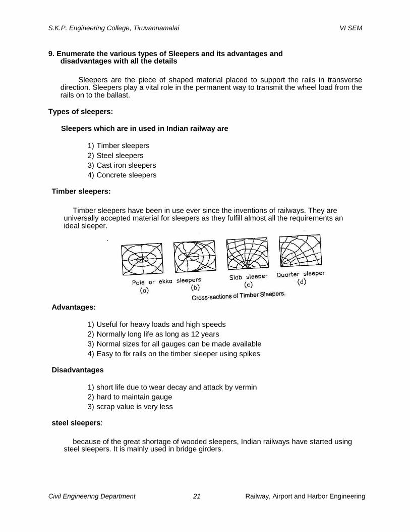
Timber sleepers:
Timber sleepers have been in use ever since the inventions of railways. They are
universally accepted material for sleepers as they fulfill almost all the requirements an ideal sleeper.
Advantages:
1) Useful for heavy loads and high speeds 2) Normally long life as long as 12 years 3) Normal sizes for all gauges can be made available 4) Easy to fix rails on the timber sleeper using spikes
Disadvantages
1) short life due to wear decay and attack by vermin 2) hard to maintain gauge 3) scrap value is very less
steel sleepers:
because of the great shortage of wooded sleepers, Indian railways have started using
steel sleepers. It is mainly used in bridge girders.

S.K.P. Engineering College, Tiruvannamalai VI SEM
Civil Engineering Department 22 Railway, Airport and Harbor Engineering
Advantages:
1) less and simple form of fastenings 2) comparatively long life 3) maintenance and adjustment of gauge are easy
Disadvantages:
1) High initial cost 2) Susceptible to corrosion 3) Not suitable for track circuited areas 4) During service formation of cracks on rail seats
Cast iron sleepers:
It may be of pot type or plate type. Advantages
1) Corrosion resistant 2) High scrap value
Disadvantages
1) Requires a large number of fittings. 2) As there is a possibility of tie bar to bend gauge maintenance is difficult
Concrete sleepers
1) Block type RCC sleepers connected by a steel tie bar 2) Pre tensioned or post tensioned pre stressed concrete sleepers 3) Pre-stressed concrete block and steel tie bar

S.K.P. Engineering College, Tiruvannamalai VI SEM
Civil Engineering Department 23 Railway, Airport and Harbor Engineering
Advantages:
1) They can be used in track circuited areas 2) Comparatively long life
Disadvantages:
1) Difficult to handle and lay 2) Heavily damaged during derailment 3) No scrap value
10. Explain the various types of horizontal curves. Give all in detail with neat Sketch
1) Simple curve 2) Compound curve 3) Reverse curve 4) Transition curve
Simple curve:
It is a curve consists of a single arc with a constant radius connecting the two straights
or tangents

S.K.P. Engineering College, Tiruvannamalai VI SEM
Civil Engineering Department 24 Railway, Airport and Harbor Engineering
Compound curve:
When a curve consists of more than one radius connecting two intersecting straights it
is called a compound curves
Reverse curve:
When two curves of different or equal radii are bending in opposite direction then it is called a reverse curve. Reverse curves have one common tangent.
Transition curve:
A curve having a gradual varying is called a transition curve. For example a curve with
infinite radius in the beginning and varying gradually to a finite radius .

S.K.P. Engineering College, Tiruvannamalai VI SEM
Civil Engineering Department 25 Railway, Airport and Harbor Engineering
TWO MARKS QUESTIONS AND ANSWERS
1. What are the purpose of signaling? (AUC NOV/DEC 2012)
1. To provide the adequate safety to trains 2. To give direction Indicators to trains at diverging junction 3. to maintain safety distance of train 4. To provide the necessary facilities 5. To permit the Trains to the restricted speed
2. What is a marshalling Yard? (AUC NOV/DEC 2012)
The main function of a marshalling Yard is to sort out wagons received from the centers to their respective destination. Further all Empty Wagons are stored and allotted as and When needed
3 . Define Heel Divergence? (AUC NOV/DEC 2010)
This is the distance between the Gauge faces of the Stock Rail and the tongue Rail at the Heel of the Switch. It is made up of Flange way Clearance and the width of the tongue rail head lies at the heel
4. What are the sources of moisture in the track (AUC NOV/DEC 2011)
1. By gravity 2. By capillary action 3. From adjacent areas 4. By hygroscopic action
5. What is meant by track Circuiting ? (AUC APRIL/MAY 2011)
Track circuiting is an Electric circuiting Formed by Combining Running rail, Signal and Cabin. It is the prime Function is to Specify the presence of the any train or the vehicle on the track .Various types of the circuiting
1. D.C Track Circuiting 2. A.C Track circuit 3. Electric track circuit
6. Modern methods of track maintenance (AUC APRIL/MAY 2011)
1. Track maintenance 2. measured Shovel Packing 3. Direct Track maintenance

S.K.P. Engineering College, Tiruvannamalai VI SEM
Civil Engineering Department 26 Railway, Airport and Harbor Engineering
7. What is meant by interlocking (AUC APRIL/MAY 2012)
Interlocking is a system meant to ensure the safety of the trains. By interlocking it is meant that Various lever operating the signals and points follow a certain Defined mechanical Relationship such that no adverse effects are possible
8. What is meant by interlocking by interlocking Signal (AUC APRIL/MAY 2012)
Based on the Signal and telecommunication Equipment is provided ,Interlocking Standards are specified By Indian Railways Based on the Speed of passing train
9.Distinguish Between the point rail and splice rail
The point rail and splice rail are machined to form a nose . The points rail is made to end at the nose Whereas then splice rail is joined a little behind the nose
10. What are the Advantages of using through sleepers (AUC NOV/DEC2010)
Through sleepers are provided for the entire length of Wherever points and crossing are provided on a track. Through sleepers main train several rails at the same level . further it is possible to fix the alignment of the curved track in relation to the straight track
11. What is co acting signal (AUC NOV/DEC2010)
Due to some obstruction if the vision of the signal is prevented, thus another signal is used in its place, preferably on the same post. Such a signal is called as co-acting Signal which ism an exact replica of the original
12.What is meant by fixed signals (AUC MAY/JUNE 2012)
Fixed signals are firmly fixed on the ground by the side of the track and can be further subdivided into caution indicators and stop signal. Caused signals are fixed signals provided for communicating to the driver that the track ahead is not caution indicators and stop signals
13.Distinguish between a railway and railway yard.
A railway station is that the place on a railway track where different types of the traffic are dealt and performs as an authority to grant permission to proceed vehicles forward
A railway yard is a system of tracks laid out in order to deal with the passenger as well as goods
14. What are the track resistant’s?
The movement of a train on a track is resisted by various factors . these resisting factors may be due to the friction between the rail and the wheel, irregularities of the on the track profile, atmospheric resistance
15. What are the Fixed Signals
Fixed Signals Re Firmly Fixed on the Ground By the Side of the track and it be further subdivided into caution indicators and Stop Signals
Stop signal are the fixed signals that normally do not change their position. They inform the drivers ahead is not fit running’sthetrainat

S.K.P. Engineering College, Tiruvannamalai VI SEM
Civil Engineering Department 27 Railway, Airport and Harbor Engineering
16 MARKS QUESTIONS AND ANSWERS
1.Draw a neat diagram and Explain the signals used at various locations along the standard Prescribed for such location (AUC NOV/DEC 2010)
Definition
Signaling is used To access the safety of a route .in the real sense signaling forms a medium of communication between the station master to the driver
Objectives of signaling
1. To provide the Adequate safety to trains 2. To give direction Indicators to trains at diverging junction 3. to maintain safety distance of train 4. To provide the necessary facilities 5. To permit the Trains to the restricted speed
Types of Signaling
1.Signal based on function 2. Signal based on location 3.Special Signal
1.Signal based on function
The signal comprises of the signaling the driver of a signal to Stop, move casually ,proceed and to carry out Shunting Operation
1.Stop signal 2. Warner Signal 3. Disk or Ground Signal 4. Colored light Signal
1.Stop signal
Stop Signals are fixed Signals Which are also as semaphore signals .the semaphore signals function in a following Way 1.The semaphore arm is capable of making two positions 2.The horizontal position of the signal indicates 3.When it is lowered at an angle of 45°-65° .it indicates proceed and is 4.The important features of the this types ,if anything goes to bad with the apparatus, the signal Should Show the Stop position

S.K.P. Engineering College, Tiruvannamalai VI SEM
Civil Engineering Department 28 Railway, Airport and Harbor Engineering
2. Warner Signal
Warner signals are similar to semaphore Signals with a difference that a V-notch is provided at the free end. The signal is placed ahead of semaphore signals. The main function of the signaling is to warn the driver about the presence of a Stop Signal Ahead Working position of Signal
1.When in Horizontal or in “on posi
Danger position
2.When in inclined position it- POSITION”signifies. that i.e. th any danger
3. Disk or Ground Signal
Disk or Ground Signal are miniature Signals Which are to used for Shunting of Vehicle in Station yards. these are called Shunting Signals .
The disk is removed by a suitable arrangement. Two holes one is provided are for red lamp and the other for the green lamp
When the red band assumes inclined position as Shown it indicates the proceed While at horizontal position it Signifies Stop.

S.K.P. Engineering College, Tiruvannamalai VI SEM
Civil Engineering Department 29 Railway, Airport and Harbor
Engineering
4. Colored light Signal
In order to Signify the track conditions to the driver at all times ,these Signals used colored light. Further to Ensure good visibility of the lights Even in Day time Special Electrical connection Using lenses are made
Types 1.two aspect, namely red and green 2. three aspect, namely red, yellow and green 3. four aspect, namely red and green, yellow(twice)
2.Signalling based on the function
These signals are placed around a station yard occupying certain defined location. different types of signal under this category are
1. outer Signal 2. Home signal.
3. Starter Signal 4.Advance Starter Signal

S.K.P. Engineering College, Tiruvannamalai VI SEM
Civil Engineering Department 30 Railway, Airport and Harbor Engineering
1. outer Signal
Bringing a train an motion to Stop Depends on the Weight of the trains ,Brake the power of the locomotive, Speed of the train and gradient at the site
The distance travelled is nearly Equal to 0.54km for B.G and 0.40 km for M.G for the maximum allowable Speed in India
2. Home signal.
This is located Exactly at the Station limit. its main functions is to be Safeguard the Station and junctions.
Only home signals permit the train to entire platform. the unprotected distance between the home Signal and Points is a maximum of 180m
3. Starter Signal
This signal is located at the forward end of the platform. Its function is to control the movement of the trains as they leave the Stations
4.Advance Starter Signal
This signal is provided to carry out Shunting operation within its protection. these Signals may be of disk types Signals ,Small Semaphores or any Suitable form of small lights
It is necessary to provide sufficient Space between Signals and the sliding so as to allow the maximum likely length of the train

S.K.P. Engineering College, Tiruvannamalai VI SEM
Civil Engineering Department 31 Railway, Airport and Harbor Engineering
2. Explain the various types of Level crossings and remedial measures. Give all in detail (AUC
NOV/DEC 2010) Definition
Railway lines to cross the a road at the different elevation. If the level of the passing and traffic is the same as that of the railway track, the crossing is called as the level crossing
Types of level crossing
Level Crossings are may be Guarded or unguarded. In the case of guarded some method of preventing the movement of the train of the road vehicles is done ,this method may be Swing type gates
These gates of manned crossing are either operated automatically or by watchman of rails. Incase of Unguarded leveling no watchman is provided
Classifications
1. Special class level Crossing 2. Class A level crossing 3. Class B level crossing 4. Class C level crossing 5. Class D level crossing
1. Special class level Crossing
These Types of level Crossing are the busiest ones in terms of road traffic. All level Crossings in National Highways are Special Classes. The Gates of the Level crossing are interlocked with the signal. These Crossings are generally Guarded for 8 –hour Shifts
2. Class A level crossing
Most of the important roads are provided with this types of level Crossings. This is also a busy Level Crossing in terms of road traffic. Other Provisions are Similar to Special Aspect with only two Gateman are provided to work on 12 –hour shift basis
3. Class B level crossing
These crossings are relatively less busy. These are Provided on metal led roads . These gates of the Crossings are Closed to road traffic and open to traffic provided that the gates are interlocked with signals. Here also only two gateman are assigned to work on 12-hour shift basis
4. Class C level crossing
These are provided mostly on un medaled roads. Evidently the volume of the traffic is less. For the reason Some of these Crossings are unguarded. If manned only ones gateman is provided.
5. Class D level crossing These types of level Crossings are provided f
move

S.K.P. Engineering College, Tiruvannamalai VI SEM
Civil Engineering Department 32 Railway, Airport and Harbor Engineering
3. Draw a neat Sketch of Points and crossings. Describe its components in detail (AUC NOV/DEC 2011)
Definition
Points and Crossing are provided to transfer railway vehicle from one track to another
track. The tracks may be of converging type or diverging types. As the wheel of the railway
vehicle are made with Flanges, there is need of points and Crossings for Easy movements for
easy movement
Points or Switches
A Switch forms a combination of a pair of tongue and stock rail properties connected
Crossing
A crossing is a device provided at the junction of two rails .This is to permit the wheel flange of a railway vehicle to pass from one track to another track
Points or Switches A set of points or Switches comprises of the following components
1) A pair of Stock rails
2) A pair of tongue rails of Switch rails, PQ and RS, which are machined so as fit with the Stock rail. The tapered end of a tongue rail is called the toe and the thicker end is called heel
3) A pair of heel blocks are provided Which hold the heel of the tongue rail at the Standard clearance
4) A number of Slide Chairs are Provided in order to support the tongue rail and thereby enable its movement towards or away From the Stock Rail
5) In order to hold the tongue rails are closed to the toe at a fixed Distance two or more Stretcher bars are connected
6) A gauge tie Plate to fix Gauges is provided and also to Ensure correct gauge at the points
Types of Switches
1. stud Switches
In stud switches , no separate tongue rail is provided. These Switches are not in
use in Indian Railways, and has been Replaced by Split Switches
2.Split Switches
Split Switches are Consist of a pair of Stock rails and a pair of tongue Rails

S.K.P. Engineering College, Tiruvannamalai VI SEM
Civil Engineering Department 33 Railway, Airport and Harbor Engineering
Types 1. Loose Heel type 2. Fixed type
Crossings
A crossing is a device provided at the point at the Two Gauge Faces Cross Each other. This arrangement is made to permit the Flanges of a railway Vehicle to pass from one track to another
Crossing Comprises of the Following Points 1)The points rail and Splice rail are machined to form a nose. The point rail is made to end at
the nose whereas the splice rail is joined a little behind the nose 2) two wing rails one of the right hand and other of the left hand are arranged to form a throat
and Again and again diverge on either side of the nose. In order to facilities the entry and exit of the flange wheel in the Gap.
3. A pair of the Check rails are provided to guide the Wheel Flanges and to route a path of them
Crossings are classified into Three Types
1.Acute angle Crossing
2.Obtuse angle Crossing
3.Square Crossing
1. Acute angle Crossing
It is also called as an “V crossing” in Which a Crosses a left rail 2.Obtuse angle Crossing
It is also called as diamond Crossing in Which two Gauge Faces meet at an Obtuse Angle
3.Square Crossing
It is one of the tracks cross at right angles. Such a situation rarely occurs in practical

S.K.P. Engineering College, Tiruvannamalai VI SEM
Civil Engineering Department 34 Railway, Airport and Harbor Engineering
4. Explain about Track Drainage, and how Surface and Sub surface Water Can be removed From Railway track. Give all in Details (AUC NOV/DEC 2011)
Definition
Drainage of a track, Station Yards and platforms are the three places Where Drainage arrangements are needed. Track Drainage Comprises of Interception, Collection and disposal of from the track. This is done by adopting proper Surface and Subsurface Drainage System Types of track Drainage
Surface Drainage
Surface Water due to rain or Snow or Flow From Adjacent areas have to be Disposed of Through Surface Drainage. Surface Drainage has to be attended to in three locations. Drainage in mid- Section Between railway Stations
1.Drainage in mid-section
2.Drainage in Station Yards
3.Drainage at Station Platforms
1.Drainage in mid-section
A typical arrangement of cross Section of a mid-section. Side Drains may be unlined or
lined. At a level Crossing all water should flow to the side Drains. In cutting catch water Drains
Have Been Provided Wherever Necessary. All Extra Ballast on the Side Should be Recovered
Which Encourage Growth of the vegetation.

S.K.P. Engineering College, Tiruvannamalai VI SEM
Civil Engineering Department 35 Railway, Airport and Harbor Engineering
2.Drainage in Station Yards
Open Surface Drains-Shaped Drains, Longitudinal Drains and Open Drainage are Provided to Free Station Yard From Water
A typical surface drainage system with open Drains for a Station Yard .Every Station Yard is Provided with a network of Cross and Longitudinal Drains. In Station Yard the vulnerable points are water columns and carriage watering points with washing Hydrants.
3.Drainage at Station Platforms For Drainage of Station Platforms the following Points Should be Taken into account
1.Slopes away From the track 2. Discharge on non-Track Side 3. Discharge not towards Ruin-through lines
In general all end of platforms should be sloped away From the Track. all other Discharges Form tea Stalls, Toilets, Water taps. If there is need be , covered longitudinal Drains Should Be Provided Incase of island platforms, all Drains Should discharge on the less important side of the track

S.K.P. Engineering College, Tiruvannamalai VI SEM
Civil Engineering Department 36 Railway, Airport and Harbor Engineering
2.Sub-Surface Drainage
Sub-surface water is due to the capillary water. Other sources are seepage from adjacent areas percolation of rain water. The sub grade and the formation are immediately affected by the Sub-Surface irrigation
1. Provision of an inverted fillers 2. Sand piling 3. Laying of Geotextiles 4. Other Methods
1. Provision of an inverted fillers
An inverted fillers blanked of adequate thickness is provided between the ballast and the week formation. The Blanket is of non-Cohesive material with enough bearing capacity to sustain the load thereon
The inverted fillers Blanket is a very effective method of improving the bearing capacity. It serves as a porous medium to drain to drain off the Surface Water and Serves as a barriers for the upward movement of fine Grained particles 2. Sand piling
Sand filling is an effective technique . A series of 30cm diameter vertical holes are drilled
inside and outside the rail to a depth of 2-3m. the holes are filling with clean sand and the
surface is resurfaced. The area covered by the Sand piles Should be About 20% of the
formation area. Sand piles provide a mechanical support and the Drainage of the Sub grade
improves
Further by the arrangement of the Subsoil rises through the sand column And get evaporated.

S.K.P. Engineering College, Tiruvannamalai VI SEM
Civil Engineering Department 37 Railway, Airport and Harbor Engineering
3. Laying of Geotextiles
Geotextiles are made of polymers which are Extensively as a new Technique in improving the Soil Properties and Drainage
On Indian railways Geotextiles are Extensively used. Geotextiles are having the unique property to allow water to pass through but not the soil fines. They not only Work as separate and filters But also as reinforcement bed
Geotextiles are either laid directly below the ballast or sandwich between a 50mm layer of sand on top and a 25mm layer so sand below so that the ballast directly does not rest on Geotextiles . and thereby preventing tear and puncture of textiles .
4. Other Methods
All other methods Which are used to for Soil Stabilization may be used to arrest Sub-Soil water. Cement Grouting , Chemical Grouting 5. Draw a neat diagram of simple right hand turnout and Show its various components. Explain the Working Principal of Turnout (AUC NOV/DEC 2012)
Definition
Turnouts are the simplest Combination of the Points and crossing Which enables one track to another track either a branch line or a sliding, To take off From Another From another track Parts of the Turnout
1. A pair of points or Switches 2. A pair of Stock Rail 3. A vee Crossing 4. Two Check Rails 5. Four Lead Rails 6. Stud or Stops 7. Bearing plates

S.K.P. Engineering College, Tiruvannamalai VI SEM
Civil Engineering Department 38 Railway, Airport and Harbor Engineering
Important terms used in Turnouts
1.Facing direction 2. Trailing Direction 3. Facing point of Turnout 4. Trailing point of Turnout 5. Right hand and left hand turnouts 6. Right hand and left hand Switches
1.Facing direction
If someone Stands at the toe of Switch and looks towards the Crossing, then the Direction is Called “Facing Direction”
2. Trailing Direction
If someone Stands at the Crossings of Switch and looks towards the Crossing, then the Direction is Called “Trailing Direction”
3. Facing point of Turnout
In this train pass over the Switches and then they pass over the crossing first and then they pass over the crossing. These are important to Specify the The direction of movement of Trains is reserved for facing direction
4. Trailing point of Turnout
Those opposite sides of the Spacing points in Which the trains pass over the Crossing first and then pass via Switches. These are important to Specify When the Direction of Movement of trains is reserved for trailing direction only.

S.K.P. Engineering College, Tiruvannamalai VI SEM
Civil Engineering Department 39 Railway, Airport and Harbor Engineering
5. Right hand and left hand turnouts
If a train From a main track is diverted to the right of the main route in the facing
direction .then the diversion is Known as an Right-hand Turnout. If a train From main Track is
Diverted to the left of the main route in the Facing Direction, Then the Diversion is Called left
hand turnouts
6. Right hand and left hand Switches
These are termed as Left-Hand or right hand Switches Depending upon the left of Right When Seen From The facing Direction, i.e. Stand at the Points and look Towards the Crossing
6. How are stations classified? Explain the features of each station. (AUC NOV/DEC 2012)
Definition
Stations and Yards are field control units of the communication System. Further they also provide waiting places and repairing places for the locomotives and wagons
A railway Station is that places on a railway track Where different types of traffic are dealt and performs as an authority to grant permission to proceed vehicle forward
Purpose of Railway Stations
1. To control the incoming and outgoing movement of a train 2. To collect food and water for passenger 3. To load and load goods or parcels

S.K.P. Engineering College, Tiruvannamalai VI SEM
Civil Engineering Department 40 Railway, Airport and Harbor Engineering
4. To enable the locomotives to refill, diesel, water and coal 5. To provide facilities for a change of engine
Classification of railway Stations
Railway Stations are Classified based on two Broad Categories. That are Given below
1.Railway Station Based on operational Consideration 2.
Railway Station Based on functional classifications
1.Railway Station Based on operational Consideration
As per the Indian Railway, railway Station are classified as block Station or non-Block Stations.
1.Block Station
Incase of Block Station no traffic is dealt but trains have to get the permission to proceed further. Block Stations are further classified as A,B,C Classes
Class A
The lines on Which the in Coming Trains is received after clearing at least a distance
of 400m beyond the home Signal

S.K.P. Engineering College, Tiruvannamalai VI SEM
Civil Engineering Department 41 Railway, Airport and Harbor Engineering
Class B
Permission to the incoming trains is given before the receiving lines is made clear within the Station section
Class C These are the stations where trains do not stop
2. Non-Block Station
Non Block Stations are classified as D-Class of Flag Stations. In this station only traffic is dealt and there are no arrangement made to Control the movement of the trains. They are located in Between Two block Stations
2. Railway Station Based on functional classifications
Here the Stations are classified Based on the function they are Expected to perform. Under this Category the Following Stations are Grouped
1. Halt Station 2. Flag Station 3. Wayside Station 4. Junction Station 5. Terminal Stations
1. Halt Station
This is a Simplest Station Where Trains Can Stop on a railway line. The level of the Platform of the halt Station is same as that of rail level. Name Board are Placed on Either end. No Stations Yard or Building or Staff Provided for Such Stations.
However, A Small waiting Shed is Provided, Sometimes, Which Serves the as a book office. Booking is done by Travelling ticket Examiner or booking Clerk 2. Flag Station
A Flag Station is Provided with a Station Building and Staff. This is better that a halt Station. The Stations Buildings Accommodates a Small Waiting hall and a booking office
Further a Platform, Benches and Drinking Water Facilities are made Available Sometimes Siding is also Provided For Stabling of Wagon booked for that Station

S.K.P. Engineering College, Tiruvannamalai VI SEM
Civil Engineering Department 42 Railway, Airport and Harbor Engineering
3. Wayside Station
This is also Called as Crossing Station. In Such Stations, There is Provision made to Cross an up and a down trains or for over taking the Slow –Moving trains by the Fast-moving trains
A track Layout Has been Specific Advantages
1) It is a three-lines Station Which Can Be receive trains From Both Sides.
2) As they are two platforms , regular and an island platforms , trains may be Stopped
simultaneously. Land line may be used for goods train and the Important trains may be halted near the Station Buildings.
3) Dead end Siding Are also provided on both Sides Which will Help to accommodate sick-wagons
4) The footing over Bridge Can Be Used to Move and to go or Return Through Both the Platforms
4. Junction Station
A junction Station is the Meeting Point of three or more lines coming different from different conditions
a) There is feasibility to interchange of traffic between main and Branch line b) There is possibility to Clean and Repair Vehicle Which terminate at the junctions
This Junctions may occurs between a single main line and a single or a single or double main lines or between the double branch line and main tracks
5. Terminal Stations
A Station at Which a railway lines or one of its Branches ends or terminates Without Further proceeding is termed as terminal Station or Terminal Junction
Terminal Stations are Provided with facilities to reserve the locomotives, Examination pits, additional Sidings, Etc. Hydraulic Buffers are provided at the Ends
The Circulating Area is Provided with ticked office, restaurant, Etc Directly connected to road Such that the passenger can make use of road vehicles easily

S.K.P. Engineering College, Tiruvannamalai VI SEM
Civil Engineering Department 43 Railway, Airport and Harbor Engineering
2 MARK QUESTIONS AND ANSWERS
1.Define wind Coverage (AUC NOV/DEC 2010) ,(AUC NOV/DEC 2011)
The percentage of time in a Year During Which the cross-wind components remains within the limits is called the wind coverage .For busy Airport the wind coverage may be increased to as much as 98 to 1007
2.What are the Factors Affecting airport operating capacity (AUC NOV/DEC 2010)
The number of aircraft movement Which an airport Can process within a Specified period of time , with an average delay in to the departing aircraft within the acceptable range
3.Distinguish Between Runway and taxiway (AUC NOV/DEC 2012)
Runway is a long Rectangular Strip, which is Constructed with Adequate Strength for landing and takeoff of Aircraft at an Airport
A Strip of Pavement connecting the apron to the Hanger as well as Runway ends
to the Apron is called Taxiway
4.Listout the four Standard Factor Conditions involved for the Design of Runways (AUC NOV/DEC 2009)
Runway Geometric design comprises of the following Elements as per ICAO
recommendations. That are 1. length of the runway 2. Width of the Runway 3. Longitudinal Slope or Gradient 4. Transverse Slope of cross Gradient 5. Sight distance 6. Runway Surface 7. Runway Strips 8. Runway- end safety areas 9. clearway 10. Stop ways
5.Define Cross Wind component and Wind coverage (AUC NOV/DEC 2009)
If the direction of wind with awithVelocitythecentreline of V of the runway , Its components perpendicular to This normal components of the wind is called the Cross-wind Components
The percentage of time in a Year During Which the cross-wind components remains
within the limits is called the wind coverage .For busy Airport the wind coverage may be increased to as much as 98 to 1007

S.K.P. Engineering College, Tiruvannamalai VI SEM
Civil Engineering Department 44 Railway, Airport and Harbor Engineering
6. How much Correction Should be made in the Runway Length for Gradient
(AUC MAY/JUNE 2011) 1. C
orrection for elevation 2. Correction for Temperature 3. Correction for elevation and temperature 4. Correction for Gradient
7.What is an Exit Taxi way (AUC NOV/DEC 2011) Exit taxiway are the Taxiways Which are Provided ti minimize the Runway occupancy
time by the landing Aircraft
8. Write any Three Components of an Airport (AUC MAY/JUNE 2011)
1. Types of Airport (a) Based on Function (b) Based on Usage (c) Based on Utilities (d) Based on type of Aircraft
2. Landside Part of an Airport (a) Terminal Area (b) Terminal Building (c) Service for the Air passenger (d) Government Agencies (e) Security Arrangement
3. Airside part of an Airport (a) Runway (b) Taxiway (c) Apron (d) Holding pad or Bay (e) Navigational Aid
` (f) Hanger (g) Landing Indicators

S.K.P. Engineering College, Tiruvannamalai VI SEM
Civil Engineering Department 45 Railway, Airport and
Harbor Engineering
9. What are the data Required before the site Selection for new airport
(AUC MAY/JUNE 2012)
The class of the
Airport , viz., national, the Size and the Shape , Runway and Taxiway Requirements
The peak-hourly volume of air traffic to be Handled now and in Future The various types of operational Control to be Used
To provide facility now based on the airport and Anticipated additional facility
10.Wing rose Diagram
Using a Diagram is plotted called wind rose Diagram. There are two Types that re Given Below
Type 1 : Showing direction and Duration of Wind
Type 2 : Showing Direction, Duration and Intensify of Wind.
11.List the Various imaginary Surfaces around the Airport 1. Approach Surface 2. Horizontal Surface 3. Conical Surface 4. Take-off climb Surface 5. Transitional Surface.

S.K.P. Engineering College, Tiruvannamalai VI SEM
Civil Engineering Department 46 Railway, Airport and Harbor Engineering
16 MARK QUESTIONS AND ANSWERS 1.The length of the runway under the Standard condition is 1620 m. The airport site
has an Elevation of 270m. And the reference temperature of the airport is 32.90 0 C
. It is decoded to construct the runway with can effective Gradient of 0.20 %. Determine the Corrected length of the Runway (AUC NOV/DEC 2010)
Step 1 : Correction for Elevation
Correction = 7*1620*270/100*300 = 102.06 m
Corrected Runway Length = 1620+102.06
=1722.06 m
Step 2: Correction for Temperature
Standard Atmospheric temperature at the Elevation = 15 0 C -0.0065*270
=13.25 0 C
Rise of the temperature = 32.90 0 C - 13.25
0 C
=19.65 0 C
Correction = 1722.06*19.65/100
= 338.38m
Correction Length = 1722.06+338.38
=2060.44 m Step 3. Combined Correction
Combined Correction for the Elevation and temperature =2060.44-1620*100/1620
=27.18%
As per ICAO this combined correction Should not Exceed 35 %
Hence the correction is ok
Step 4. Correction for Gradient Applying Correction for the Effective Gradient at the rate of 20% for Each 1 % effective Gradient
Correction = 20*2060.44*0.20 /100

S.K.P. Engineering College, Tiruvannamalai VI SEM
Civil Engineering Department 47 Railway, Airport and Harbor Engineering
=82.41m
Corrected Length = 2060.44 + 88.41 =2142.85 m
above value may be rounded to the nearest 10 m, then the corrected length
Correction Length = 2140 m 2.What are the basic pattern of Runway Configuration ? Discuss Each pattern in
all the Details. (AUC NOV/DEC 2010)
The capacity of an Airport is based on the number of runways and their configuration. the pattern of runway is mainly Governed by the Volume of Air traffic to be Handled
Basic Patterns of Runway are 1. Single Runway 2. Parallel Runway 3. Intersecting Runway 4. Non-Intersecting Runway
1.Single Runway Pattern
The capacity of the runway patterns. It is Usually Adopted When the wind direction is on the Direction for the most of the time in a year and the air traffic is not Very High
Under the Visual Flight rules, A single Runway can Handle about 45 to 60 operations or movement per hour. Under the Instrument Flight rules Capacity of Single Runway is reduced to about 20 to 40 operations per hour
In a single pattern runway only one operation., i.e landing of take off can be done at a
time.
2. parallel Runways
Capacity of parallel runway pattern is based on the lateral Spacing Between the Two Runways, Number of Runways , the weather conditions and the navigational aids provided at the airport

S.K.P. Engineering College, Tiruvannamalai VI SEM
Civil Engineering Department 48 Railway, Airport and Harbor Engineering
The Spacing Between the two parallel Runway Varies significantly
1. Close Spacing 2. Intermediate Spacing 3. Far Spacing
1. Close Spacing
For this case the Spacing Varies from 210 m to 750 m. Under the IFR Condition Each runway can operate with landing and Takeoff Independently. The number of operations os From 50-60
2. Intermediate Spacing
For this category, the Spacing is 750-1300 m and more. Under the IFR conditions, the arrival on one runway can be operated independently for the both arrival and departure on the other runway 3. Far Spacing
For this category, the spacing is 1300 m and more. Under the IFR Conditions the Two runway can be operated independently for the both arrival and departure. Number of operation is from 100-120m
3. Intersect Runway
This pattern of Runway is Provided When the wind in a particular Direction does not Provide the Required Coverage. Use of the Both Runway at a time Depends upon the Cross-wind Component of each Runway

S.K.P. Engineering College, Tiruvannamalai VI SEM
Civil Engineering Department 49 Railway, Airport and Harbor Engineering
Favorable wind Conditions are Prevailing the capacity of the Each runway depends
upon the direction of landing and takeoff, the lateral at the glide paths of the aircraft and the point of intersecting of the runways
Under the IFR conditions the operations vary from 40-70 and under the VFR conditions the
operations vary From yhe 50-175. For Example, for an Intersection at the middle the IFR Operations
are From 45-60 Whereas under the VFR operations are from 60-100
4. non-Intersect Runway
Non –intersecting Runways are called as Divergent or open- V Runways Diverges in Direction without the intersection Each other. This capacity of this Pattern Again on the Wind Condition
When the Flight of the Paths are Divergent the capacity of the Highest and the order of operations is 80-110.
3.Discuss in detail the factors affecting the choice of the Selection of Site for an Airport (AUC
MAY/JUNE 2010) 1. Land use and Land Values 2. Topography of the Area 3. Geological Factors 4. Grading and Drainage 5. Ground accessibility 6. Proximate to other Airports 7. Obstruction 8. Atmospheric Factor 9. Availability of Utilities
10. Aircraft Noise
1.Land use and Land Values
Depending on the size of the Airport and the Anticipated Expansion the Land Area Required Should be assessed

S.K.P. Engineering College, Tiruvannamalai VI SEM
Civil Engineering Department 50 Railway, Airport and Harbor Engineering
As a general Guide Develop without investing heavy funds on purchase on
lands. Early acquisition of Cheaper lands is always advisable 2. Topography of the Area
Topography is an important factor to be Considered as involves terrain Slope, Natural features like trees, Streams, Further for a better maintenance grading of the topography and the Drainage are the Very important
3.Geological Factors
The soil and Rock type Available at the area to be selected Should be Known. As heavy weight of aircraft is coming on a smaller area the soil and rocky Ground Should have High bring values as soil Improvement techniques are costly, soils of less bearing value may be avoided.
4. Grading and Drainage
In order to facilitate easy take off and landing , Grading and Drainage play an Vital role in the Construction and the maintenance of an airport and in turn the Site Selection. The Ground Profile Should be in a position to drain the water during floods and rains
5.Ground accessibility
Basically it is Essentially to have fast and Efficient access facilities for passengers and freight. The passengers are very much Concerned with the time taken From the Home to Airport and vice-versa
If the site is commuted by public transport it forms the Best location 6.Proximate to other Airports
Every airport has to Use certain air Space For landing and Take-off of Aircrafts. This Varies with the Type of Aircraft and the number of Aircraft used in the airport
For Example airports Using small general aviation Aircraft the Spacing of airport may be the order of 4 km whereas for jetting operated Aircrafts it could be as high as about 150km
7. Obstruction
Aircraft While landing or taking off lose or Again altitude Very Slowly as compared to the forward Speed At high altitude
In order to accommodate this long, Clearance areas are provided on either side
of runway. Such an Identified Approach area Should be Free From any Obstruction
8. Atmospheric Factor
Inadequate Visibilities affects the traffic capacity of an airport. IF there is an Future Development Industries in a site to be Selected, it has to be Avoided.
It is advantageous to locate the site in the windward direction of the city Such
that only a minimum Smoke the city is Brown over the Site 9. Availability of Utilities
It is a general advantageous to utilize the General utilities Such as main power line, water Supplies , Sewage disposal. Telephone Services, fuel, Availability and use of these facilities may reduce the total cost the Project

S.K.P. Engineering College, Tiruvannamalai VI SEM
Civil Engineering Department 51 Railway, Airport and Harbor Engineering
10. Aircraft Noise
Construction materials like Stone can be Clearly Obtained if Stone Quarry is Located near the Site area. Further availability and use of these water will largely economies the cost
4.The length of the runway under the Standard condition is 1600 m. The airport site
has an Elevation of 320m. And the reference temperature of the airport is 33.60 0 C . It
is decoded to construct the runway with can effective Gradient of 0.25 %. Determine the Corrected length of the Runway (AUC NOV/DEC 2010) Step 1 : Correction for Elevation
Correction = 7*1600*320/100*300
= 119.46 m
Corrected Runway Length = 1600+119.46 =1719.47 m
Step 2: Correction for Temperature
Standard Atmospheric temperature at the Elevation = 15 0 C -0.0065*320
=12.92 0 C
Rise of the temperature = 33.60 0 C –12.92
0 C
=20.68 0 C
Correction = 1719.47*20.68/100
= 355.58m
Correction Length = 1719.47+355.58
=2075.05m Step 3. Combined Correction
Combined Correction for the Elevation and temperature =2075.05-1600*100/1600
=29.69%
As per ICAO this combined correction Should not Exceed 35 %
Hence the correction is ok
Step 4. Correction for Gradient
Applying Correction for the Effective Gradient at the rate of 20% for Each 1 % effective Gradient
Correction = 20*2075.05*0.25 /100

S.K.P. Engineering College, Tiruvannamalai VI SEM
Civil Engineering Department 52 Railway, Airport and Harbor Engineering
=103.75m
Corrected Length = 2075.05 + 103.75 =2175.80 m
To above value may be rounded to the nearest 10 m, then the
Correction Length = 2170 m
6. Explain in Detail About Airport Zoning (AUC NOV/DEC 2010)
Zoning Laws
Zoning laws Should be primarily Control the following
1.To regulate the Construction of height of the Structure as per the permissible limit norms
depending upon the type of airport and the Aircrafts Which are intended to use the Airport
2. To prevent the manufacturing of certain items which may result the Smoke nuisance, odour, Etc
3. To announce for compensation to the affected party if the Zoning Ordinance is likely to be Provocateur
1.Approach Zone
During the time of landing, an Aircraft Choose a particular path is called as the glide path. The glide path of an aircraft varies from a steep of the flat Slope
A wide clearance area has to be identified Which is Known as Approach Zone.
These Zone are Required on either Side of the Runway along the Direction of the landing and take off of Airport
T he plan of an Airport Approach Zone and Approach Surface is one and the Same. But the approach Zone is an imaginary Whereas the approach area is the Actual Ground area
1.1 Clear Zone
Clear Zone is the inner most part of the Approach area Which is the most Critical area. The detail of the clear Zone Instrumental and Non-instrumental Runway
It is Generally recommended to procure adequate land for Effective Implementation of Zoning laws.

S.K.P. Engineering College, Tiruvannamalai VI SEM
Civil Engineering Department 53 Railway, Airport and Harbor Engineering
It is Enough to clear all the Obstructions. Minor Obstruction Such as fences, ditches, ect may be allowed
1.2 Highway and Runway Clearance
Highway Runway Clearance are not Considered as objectionable in the Clear Zone. As a matter of the fact Even vehicle movements are allowed but they Have to comply with the Clearance Standards Laid down in the Zoning Laws
The essential Clearance needed are reflected as follows
2. Turning Zone
The turning zone is the area in an airport other than the Approach area. It is intended for turning operations of an aircraft in terms of emergencies like some troubles in airways
In such cases, the pilot takes the turn and comes in line with the runway before the

S.K.P. Engineering College, Tiruvannamalai VI SEM
Civil Engineering Department 54 Railway, Airport and Harbor Engineering
landing
In a situation like this the Aircraft operate at low height in the turning Zone and So the Turning Zone Should be free from the Obstructions
Turning Zone Profile of a runway with the Instrument Landing Facilities is
Shown Given Below
For an Airport With the Airport landing System the following points to be Considered
1.Any object located within a Distance of 4.5 km From the airport references point is treated as an Obstruction, If the Height of the Object is more than 51 m above the Ground of the Airport Elevation Whichever is more.
2. For object located Beyond 4.5 km. the additional height of the Object is considered is more 30 m for Every 1.5 km distances from the Airport Reference Point
7 . What is meant BY Airport Zoning. Discuss all in Detail
The wind data Comprising of Direction, duration and intensity are graphically represented by a diagram called Wind rose. In order to Obtain an average wind data Should be collected at the proposed location for at least for 5 to 10 years
Type 1 : Showing direction and Duration of Wind
Type 2 : Showing Direction, Duration and Intensify of Wind
A typical wind data is Shown in the Given Table. Wind velocity less than the 6.4 kmph is considered as calm

S.K.P. Engineering College, Tiruvannamalai VI SEM
Civil Engineering Department 55 Railway, Airport and Harbor
Engineering
The duration of the wind for anyone direct ion covers the angle of 22.5 degrees
as Shown Given below
It is assumed that wind may below From any direction within the 22.5 Sectors. Based on the wind data Given in the wind rose Diagram Can be plotted
Wind rose Diagram can be plotted in the Following two ways
Type 1 : Showing direction and Duration of Wind
Type 2 : Showing Direction, Duration and Intensify of Wind
Type 1 : Showing direction and Duration of Wind

S.K.P. Engineering College, Tiruvannamalai VI SEM
Civil Engineering Department 56 Railway, Airport and Harbor Engineering
A typical Wind rose Diagram for the Wind Data Given in the following Diagram
The wind rose Diagram is plotted taking a Suitable Scale for the percentage total wind duration. Keeping this Scale the percentage total wind direction in Each Direction is plotted.
For Example 2.7 % is plotted Along the north direction for the use Scale of 1cm =20% Similarly other than values are plotted along the respective direction. All plotted points are than then joint by Straight lines as Shown in Figure
The best Direction of the Runway is generally Taken as the longest line on the wind rose Diagram. For the Example Given the best direction of runway is along the NE-SW Direction
Derivation of wind direction up to 22.5+11.25 From the direction of landing and Take off is permissible. The percentage of time in the year during which the runway can Safely be used is Obtained but summing up the percentage of time Along NNE, NE, ENE, SSW, SW, WSW.
This type of wind rose diagram does not account for the effect of Cross wind component
Type 2 : Showing Direction, Duration and Intensify of Wind

S.K.P. Engineering College, Tiruvannamalai VI SEM
Civil Engineering Department 57 Railway, Airport and Harbor
Engineering
typical wind rose diagram for the wind Data in table is represented in the following figure
Each circle represents the intensity of wind to some Scale. Here the 20, kmph, 40 kmph and 60 kmph Circles are Drawn. Each Segments represents of time in year during the wind Blows from the respective direction of particular intensity.
The procedure to Obtain the orientation of runway from this type of wind rose Diagram is Given below
1.The transparent paper Strip is placed Over the wind rose Diagram such that the critical line passes through the center line of the diagram
2. In this position , the tracing paper is rotated Such that the Sum of the following values indicating the duration of wind, within the two outer parallel lines is the maximum
3.The orientation of the runway is Obtained by measuring the bearing of the central on the transparent line at the Critical position at Which the Maximum percentage is Obtained
4.If the coverage provided by a Single runway is not Adequate, two or more
Runways are planned. This is obtained by Considering the total Coverage

S.K.P. Engineering College, Tiruvannamalai VI SEM
Civil Engineering Department 58 Railway, Airport and Harbor Engineering
UNIT 4 TWO MARK QUESTIONS AND ANSWERS
Two mark question with answer
1.Landing direction indicator
It is in the form of Tee- Tetrahedron and it is placed at the center of segmented Circle
marker. This enables the pilot to identify the direction of active runway of the Airports
2.What are beacons
Beacon is high luminous beam of light Which is used to demark any Geographical location. It is positioned above the Surrounding Ground rotated at a Specific Frequency
3. What is parallel runway marking
If there are two or more number of parallel runway they are marked as follows at the threshold
(a) Two parallel runways (b) Three parallel runways (c) four parallel runways
4.Why threshold lighting is needed
In order to decide about landing or not the identification of runway threshold is important for a pilot. For this reason ,the area near the runway threshold is given special lighting arrangements.

S.K.P. Engineering College, Tiruvannamalai VI SEM
Civil Engineering Department 59 Railway, Airport and Harbor Engineering
5.What is Airways communication?
Airways communication is usually informed through flight Service stations. The location
of these Stations are at the airport and along the Airways. The function are Two-folds 1. To relay air traffic control messages between the control airways and enrooted
Aircrafts
2. To give the Specific information to the pilot, Before and during the flight such that as weather changes, navigational aids. Airport out of uses.
6.List the various enrooted aids are provided in an air traffic controls
During the flight from the starting point to destination a pilot of an aircraft is guided by different route aid, or airways or airway aids. They are
1. Airway beacon 2. Air to ground communication 3. Direction finder 4. Marker beacon 5. Distance measuring equipment 6. Air route surveillance radar
7.list at least ten facilities to be provided in an Airport building
The facilities are
1.Enquiry counter
2.Baggage claim
section 3.Toilet
facilities 4.Waiting hall
5.Customs officer
6.General Stores
7.Control tower 8.Post office and bank
8.What are Blast fences
These are provided to deflect and dissipate the energy of the jet Exhaust. Based on the type of the protection needed. Accordingly particular type of jet is used. In general blast fences of about 2.563m height give better result at runways ends and other area are attacked by the take-off thrust
9.Why wind direction indicator is provided ?
A wind direction indicator is provided so as to indicate the pilot the direction of the wind. It is in the form of truncated cone made of fabric. White and orange colored indicator is generally used
10.What is an IFR?
IFR is the Instrumental flight Rule. IFR condition prevail when visibility is poor or the height of the cloud falls below the visual meteorological conditions. IFR is also described as “bad weather or blind flying”

S.K.P. Engineering College, Tiruvannamalai VI SEM
Civil Engineering Department 60 Railway, Airport and Harbor Engineering
11. What are the basic requirement of signaling
In order to identify and recognize various airport element by a pilot certain marking are
made on the airport area in a simple manner. By this arrangement the pilot Should be distinctly identify the landing area and the wind- Direction
Marking only helps in good weather condition. During bad weather conditions and
during night it is essential to provide the adequate lighting in the Airport. Such that the lighting Should convey similar information to the pilot during good visibility condition as the marking do in daytime. these are the basic need of signaling ( Lighting, Marking)
12.How the runway numbering is done.
End of Each runway is marked with a numbering indicating the magnetic Azimuth.
That is the East-end of an East-West runway would be marked 27 and the west end 7 13.Define the term Hanger?
In general these areas are usually flood it. However, the light Source is so mounted
that there is no glare Experienced by the pilots, pas It is recommended that the flood lights Should be mounted Above the Pavement
14.What is meant by Boundary lighting
The periphery of the entire landing area is provided with light at 90 m center to center
with a height of about 75m from the ground. I fence is provided along the boundary the lights have to be provided 3m inside the fences
In order to indicate the Hazardous approaches the boundary lights are provided with the red marker lights
15.Draw a pattern of typical motor vehicle parking in an Airport
Aircraft can be Grouped adjacent to the terminal building in a variety of ways. These
groupings are referred as to the aircraft parking System
(a) Frontal or Linear System
(b) Open Apron or Transporter System
(c) Finger or Pies System
(d) Satellite System 16 .What is the use of Airport Lighting
Marking only helps in good weather condition. During bad weather conditions and during
night it is essential to provide the adequate lighting in the Airport. Such that the lighting Should convey similar information to the pilot during good visibility condition as the marking do in daytime
All the Airports Should not be Provide the Same type and intensity of Airport lighting

S.K.P. Engineering College, Tiruvannamalai VI SEM
Civil Engineering Department 61 Railway, Airport and Harbor Engineering
Types of lighting 1. Beacons 2. Boundary Lighting
3. Approach Lighting 4. Runway Lighting 5. Taxiway Lighting 6. Apron and Hanger Lighting 7. Lighting for wind and landing direction Indicator 8. Threshold lighting

S.K.P. Engineering College, Tiruvannamalai VI SEM
Civil Engineering Department 62 Railway, Airport and Harbor Engineering
16 MARK QUESTIONS AND ANSWERS
1. What is meant by layout. Explain the various types of layout with neat Sketch
The prime factor to be consider in the design of an aircraft is the selection of the runway configuration. Different types of configuration is to be discussed as follows
The combination of all Airport leads to a smooth functioning of traffic, Optimal distance of taxies and provides Shortest route for the passengers Classifications involved in airport Layout
1. Balanced Airport Layout 2. Types of airport layout 3. Military Airport Layout
1. Balanced Airport Layout
A balanced Airport Layout Should possess the following characteristics
1.Runway length Should be safe 2.Space of loading apron Should be safe 3.Less cost of construction 4.Feasibility for future Expansion 5.landing, Take-off Should function independently 6.Approaches Should be safe 7.Economical maintenance Cost 8.Taxiway Distance fro loading apron to runway end be shortest
2. Types of airport layout
(a) Airport Layout- Single Runway (b) Airport Layout- Two Parallel Runways (c) Airport Layout- Three non-intersect Runways (d) Airport Layout-Three intersection Runways
(a) Airport Layout- Single Runway
The position of hanger, Apron, Terminal Building And taxiways Along with the runway are shown as follows

S.K.P. Engineering College, Tiruvannamalai VI SEM
Civil Engineering Department 63 Railway, Airport and Harbor Engineering
(b) Airport Layout- Two Parallel Runways
(c) Airport Layout- Three non-intersect Runways

S.K.P. Engineering College, Tiruvannamalai VI SEM
Civil Engineering Department 64 Railway, Airport and Harbor Engineering
d) Airport Layout-Three intersection Runways
Tangential airport layout

S.K.P. Engineering College, Tiruvannamalai VI SEM
Civil Engineering Department 65 Railway, Airport and Harbor Engineering
3. Military Airport Layout
Military Airport Requirement have to be looked into an different way than that of a
commercial Airport. Some of the important Airport Factors to be considered are as follows
1.Maxium number of trees have to be preserved 2.Surfece of a runway has to be Specially treated with the Specific color 3.Made as inconspicuous as possible 4. overall Layout may appear to be unusual and irregular 5. topography Should be suitable for underground installation 6. Storage Spaces for the Aircraft may be distribution widely and Scattered
2. Explain the various Aircraft parking Systems involved in Airport. Give all in detail
Aircraft can be Grouped adjacent to the terminal building in a variety of ways. These
groupings are referred as to the aircraft parking System
1.Frontal or Linear System
2.Open Apron or Transporter System
3.Finger or Pies System
4.Satellite System 1.Frontal or Linear System
In the frontal or linear system the aircraft are parked along the face of the terminal
Building. This is a simple system but adoptable to the airport with low airline activity 2. Open Apron or Transporter System
In this open Apron System the aircrafts are parked in rows. The passenger Have to walk a long distance in Exposed weather condition to reach the outmost Row. In order to protect the passenger from the adverse weather condition vehicular transport have to be provided for Enplaning and deplaning

S.K.P. Engineering College, Tiruvannamalai VI SEM
Civil Engineering Department 66 Railway, Airport and Harbor Engineering
3. Finger or Pies System
In the finger or Pier System the connection to the Aircraft is Achieved through the pier
Extending from the main terminal Area . It can be T-Shaped, Y- Shaped, or Straight. Each pier a row of Aircraft gate position on both sides. Aircraft are parked around the axis of the pier is noise-in of parallel parking arrangement

S.K.P. Engineering College, Tiruvannamalai VI SEM
Civil Engineering Department 67 Railway, Airport and Harbor Engineering
4. Satellite Parking
Satellite are Small buildings located on an Apron. In this types of System the aircraft are parked around the satellite . the satellite building is connected to the main terminal building by underground tunnels
3. What are the various Systems involved in Airport Marking. Explain in detail
In order to identify and recognize various airport element by a pilot certain marking are
made on the airport area in a simple manner. By this arrangement the pilot Should be distinctly identify the landing area and the wind- Direction
Types of Airport Marking
1. Runway Marking 2. Taxiway Marking 3. Apron Marking 4. Wind direction indicator 5. landing direction indicator
1.Runway Marking
Runway Marking Consist of 1. Runway centerline Marking 2. Runway threshold Marking 3. Runway End-Strip Marking 4. Runway numbering 5. Parallel runway Marking 6. Runway Shoulder Marking
1. Runway centerline Marking
The runway center -line is represented by a broken Strip running along the
full length of the runway. The width of the marking is 90cm

S.K.P. Engineering College, Tiruvannamalai VI SEM
Civil Engineering Department 68 Railway, Airport and Harbor Engineering
2. Runway threshold Marking
Runway threshold marking is indicated by a series of parallel lines commencing
from a distance of 6m fro the runway-end. The markings are in the from of strips 3.60m wide and with of the Spacing of
0.90m. The marking are placed Symmetrically on either side of the runway center-line
3. Runway End-Strip Marking
Edges of the runway are normally marked. Incase of with width Exceeding 45m, The Strips
is made in the form of along continuous lines of 90cm width of marked near the edges

S.K.P. Engineering College, Tiruvannamalai VI SEM
Civil Engineering Department 69 Railway, Airport and Harbor Engineering
4. Runway numbering
End of Each runway is marked with a numbering indicating the magnetic Azimuth. That
is the East-end of an East-West runway would be marked 27 and the west end 7
5. Parallel runway Marking
If there are two or more number of parallel runways they are marked as follows at the threshold
(a) Two-Parallel Runways
(b) Three parallel Runways (c) Four Parallel Runways
Considering the Azimuth of three intersecting, the numbering can be done as Shown as follows

S.K.P. Engineering College, Tiruvannamalai VI SEM
Civil Engineering Department 70 Railway, Airport and Harbor Engineering
6. Runway Shoulder Marking
The Shoulder on the edges of a runway and taxiway are paved. Although they appear
Structurally Strong they are not Capable of withstanding the Aircraft loads. Runway Shoulder marking is used as a supplement to runway side Strips. Shoulder
marking are generally needed to guide the pilot to identify the runway from the Shoulder The color of runway Shoulder marking is yellow and are located between the
runway side Strips and the pavement edges . These marking consist of Strips 1m width and Spaces 30m Apart. The Strips are marked
Slander at an angle of 45 degree to the center and Start at the Runway mid-Point
4.Explain in detail about the function of Wind direction indicator and landing indicator
Wind –direction indicator is in the form of a truncated cone made of fabric. It Should be
of 3.6 m length and 0.9 m diameter at the larger end. It should be Constructed in Such a way that it gives a clear indicating of the wind Speed. The color combination adopted Should be such that the indicator is clearly visible and understanding for the pilot from a height of 300m.
Generally, A Single color pre White or orange is used
An Airport must be Equipped with at least one wind direction indicator. The location of the wind direction indicator Should be at Such a position so as to be Visible Fro the aircraft in flight of on movement area
Provision Should be made to illuminate at least one wind direction indicator
Wind direction indicator is usually placed at the center of the segmented circle marker.
This arrangement helps the pilot in locating the airport and the wind direction indicator

S.K.P. Engineering College, Tiruvannamalai VI SEM
Civil Engineering Department 71 Railway, Airport and Harbor Engineering
The panel forming the segmented Circle markers are Gabble-roof Shaped with a pitch of atleat1 to 1. This Enables the pilot to have a better visibility from a considerable Distance. Generally panels are painted in White. As per the ICAO the inside Diameter of Segmented circle Should be 80m and the panel width varying from 0.90 to 2.40 m
LANDING DIRACTION INDICATOR
It is in the form Tee or Tetrahedron and is Placed at the center of t5he segmented Circle
This Enables the pilot to identify the direction of the Active runway of the Airport. This dimension of a typical Landing direction indicator is Shown in the above figure

S.K.P. Engineering College, Tiruvannamalai VI SEM
Civil Engineering Department 72 Railway, Airport and Harbor Engineering
5. Explain the various types of lightings involved in Airport. Give all in detail
Marking only helps in good weather condition. During bad weather conditions and during
night it is essential to provide the adequate lighting in the Airport. Such that the lighting Should convey similar information to the pilot during good visibility condition as the marking do in daytime
All the Airports Should not be Provide the Same type and intensity of Airport lighting Types of lighting
1. Beacons 2. Boundary Lighting 3. Approach Lighting 4. Runway Lighting 5. Taxiway Lighting 6. Apron and Hanger Lighting 7. Lighting for wind and landing direction Indicator 8. Threshold lighting
1. Beacons
Beacon is high luminous beam of light Which is used to demark any Geographical location. It is positioned above the Surrounding Ground rotated at a Specific Frequency
2. Boundary Lighting
The periphery of the entire landing area is provided with light at 90 m center to center with a height of about 75m from the ground. I fence is provided along the boundary the lights have to be provided 3m inside the fences
In order to indicate the Hazardous approaches the boundary lights are provided with the red marker lights
3. Approach Lighting
For a pilot While Approaching a runway of landing, the approaches lights are the only element of guidance .Actually before the Starting point of the Runway, A Sequence of High-Intensity lighting arrangement for a length of 900m provided
This form a basic guidance for the pilot to center the aircraft centrally. These lighting then give way to the touchdown Zone lights From the threshold of the Runway

S.K.P. Engineering College, Tiruvannamalai VI SEM
Civil Engineering Department 73 Railway, Airport and Harbor Engineering
There are the Two Approaches lighting System, Viz.., Calvert System And ICAO System Calvert System of approach lighting is shown in Fig.11.15. It is developed by Mr.E.S.
Calvert of Great Britain. It is Widely used in Europe and other countries
The ICAO system of approach lighting is show in Fig.11.16. This system is known as the centerline configuration system. The system is standardized by ICAO and used in USA.
4.Threshold lighting
In order to decide about landing or not the identification of runway threshold is important for a pilot. For this reason ,the area near the runway threshold is given special lighting arrangements.
The end of approach lighting is denoted by terminal bar of red lights (Fig 11.16). The
threshold is lighted fully with a continuous line of green light extending the full width of runway. The lights may be semi –flush or elevated type.

S.K.P. Engineering College, Tiruvannamalai VI SEM
Civil Engineering Department 74 Railway, Airport and Harbor Engineering
5.Runway lighting
After crossing the threshold the pilot has to complete a touch down and then roll the
aircraft on the runway. The runway lighting has to be so planned and arranged such that it provides sufficient guidelines to the pilot (1) alignment (2)
Literal displacement (3) roll and (4) height of distance and thereby he /she is able to judge correctly his /her position in the space.
In olden days practice is to flood light the entire landing area. But nowadays it is resorted to indicate the preferred direction of landing
6.Taxiway Lighting
It is necessary to provide the adequate lighting aids for taxing at nights and
in day time When the visibility is very poor Taxiways has to be clearly identified and no confusion Exist between Runway and
Taxiway. As provided in runway there Should be adequate guidance along taxiways also

S.K.P. Engineering College, Tiruvannamalai VI SEM
Civil Engineering Department 75 Railway, Airport and Harbor Engineering
Whenever Crossing of taxiways and Runway occur they Should be clearly identified.
Exist taxiway Should be properly identified Such that the pilot is able to locate along taxiway 7.Apron and Hangar lighting
In general these areas are usually flood it. However, the light Source is so mounted
that there is no glare Experienced by the pilot It is recommended that the flood lights Should be mounted Above the Pavement
8. Lighting for wind and landing direction Indicator
The illumination of wind direction indicator is done by four 200 watts angle reflector
placed 1.8 m above the top of the cone. This arrangement will be provide continuous uniform lighting at any position of the cone
The landing direction indicator Also Should be Provided With Properly lighted For all time use as done for wind direction indicator
7.Explain the need of Air traffic control . Enumerate the various features involved in air traffic control network System
AIR TRAFFIC CONTROL
Air traffic control network mainly involves two aspects
1. To Safeguard life and property 2. To expedite the traffic movement

S.K.P. Engineering College, Tiruvannamalai VI SEM
Civil Engineering Department 76 Railway, Airport and Harbor Engineering
PURPOSE OF AIR TRAFFIC CONTROL
The main purpose of air traffic control are Safety, Efficiency and economy 1.Safety The prime purpose of air traffic control is safety. Following two aspects Should be looked into
(a) Providing adequate guidance to the pilot whose vision may be obstructed during the time of landing and take-off
(b) Vision may be classified into three categories that are given as follows Category 1:
weather condition which provides a forward visibility of at least 800m. Category 2:
Forward visibility of 400m Category 3:
Zero visibility condition 2.Efficiency
This has to ensure 1. Quick and efficient movement of traffic
2. Maintaining of scheduling of flights within reasonable limits and
avoiding delays, misconnecting and discomfort to passengers
3. Avoiding waste of time causing hardship to business and effective use of Space in airways
3.Economy
In general a delay in air traffic causes loss. Any Excess time Spend in air attributes to
monetary loss of fuel, wear and tear and other expenses. Not using full airports capacity, Airways not carrying full passenger capacity and planes
idling all contributes for wasted investments AIR TRFFIC CONTROL NETWORK SYSTEMS Air traffic control network system comprises of three parts of the followings
1. Control within terminal area 2. Control over Airways 3. Airways communication
Control within terminal area
A control tower is located in the terminal area which is the nerve center of an Airport.
The entire control made by a control tower Which forms the part of the network
A control tower of an terminal area, Supervisors, Directs, And monitors the traffic at the
Airport. The tower is responsible for issuing clearance to all arriving and departing aircrafts. IT

S.K.P. Engineering College, Tiruvannamalai VI SEM
Civil Engineering Department 77 Railway, Airport and Harbor Engineering
also gives the information needed foe a pilot such as temperature, wind direction, barometer , Operating condition of the Airport
The control tower is needed in a commanding position Such that a complete clear view of the Airport is Obtained. In general control towers are constructed at the top of the Administrative buildings
The control tower having the control facilities directs the Aircrafts to the Airport through a number of Specific points. These points are located within the radius of about 40km from the control tower.
If the traffic is heavy the Aircrafts are obtained at this point are known as Holding fix. At this point the heavy aircraft are required to keep moving with the vertical separation of 300m.s
2.Control over Airways
The control is provided by a number of air route traffic control centers. Each center has command over a Specific geographical area and by this arrangement the entire area of the country is covered.

S.K.P. Engineering College, Tiruvannamalai VI SEM
Civil Engineering Department 78 Railway, Airport and Harbor Engineering
Thus the function of these centers, are separated from the Airport operation. In order
to reduce the additional communication facilities they are located at the airport The control facility is primarily concerned with the Aircraft operating under the IFR
centers Changes in the flight plan enrooted are permitted only with the approval of the control centers
3.Airways communication
Airways communication is usually informed through flight Service stations. The location of
these Stations are at the airport and along the Airways. The function are Two-folds
1. To relay air traffic control messages between the control airways and enrooted
Aircrafts
2. To give the Specific information to the pilot, Before and during the flight such that as weather changes, navigational aids. Airport out of uses.
S.K.P. Engineering College, Tiruvannamalai VI SEM
Civil Engineering Department 79 Railway, Airport and Harbor Engineering
UNIT 5
2 MARK QUESTIONS AND ANSWERS
1.What is dredging
In order to maintain the required level of water in harbor the external material deposited in the bed has to be removed from time to time. This operation of removal of material from the sea or river bed is called dredging
2.What is a break water
Break water is a Structure constructed to reflect and dissipate the force of the wind generated waves. If a natural environmental is not available to build a harbor and if it is to be Constructed on an open sea, it is necessary to protect the harbor walls artificially by breakwater
3.What is meant by Sounding? Name equipment used for sounding
For planning any maritime Structure the depth of water some distance along the coast
and in the area to be developed Should be known. Measurement of depth water the Surface of water is called Sounding
For most engineering equipment works, a boat is used for finding the Sounding using one of the following equipment
1. Sounding cables 2. Sounding rods 3. Eco sounder 4. Fathometer
4.What is water transportation?
Among the three modes of transportation, Viz., Land, air and water, water transportation has a signified historic importance. It is the main transportation which was the responsible for cultural relation and growth of civilization. Ocean water transported and inland water transportation
5.List the various features of harbor
Features of harbors are 1. Harbor entrance 2. Turning basin 3. Approach channel 4. Break water 5. Lock and locked basin 6. Dry docks and Spillways 7. Piers 8. Berthing basin

S.K.P. Engineering College, Tiruvannamalai VI SEM
Civil Engineering Department 80 Railway, Airport and Harbor Engineering
6.How to decide the entrance of the harbor A harbor Should be Easily accessible Which is based on the location. The entrance of
harbor Should be designed Such that it is Easily negotiate during the Storms. The entrance is generally placed of the sea Such that the effect of rough sea is minimum
7. Sand dunes
Sand dunes are formed along the coast Which prevent the the free movement of tides and waves into the area behind it. Sand dunes with time may to the Adjacent areas and damages the property
8.What is a Wharf? Name it’s types
A wharf is a wall build along the bank or a Shore to berth vessels for working cargo. This may be a sheet pile wall or a gravity wall. The types are Sheet pile walls and Gravity walls.
9.What is meant by Fog Signal?
Fog signals are the signals to be provided at places likely to be seriously affected by fog. These are ordinary bells Struck by hand mechanically operated submarine bells, sirens or Whistles
10. What is meant by Audible Signal?
Audible signals are to be used at the time of the Emergency in order to attract the immediate attention of marine. They may be Explosive Signals, sirens, bells, diaphones, Electric oscillation, Etc
11.What are tidal Basins?
Basins are constructed at the entrance gate position. These basins are partially enclosed areas of water Which are subjected to tidal variation. These basins are also called as tidal basins
12. What is a dock? List the various types of rocks.
Docks are enclosed areas of berthing ships in order to keep them afloat at the uniform level. Docks are classified as follows
Types of docks
(a) Dry dock (b) wet dock
13. What do you understand by littoral drift
As a result wind effect the sand is carried in a zig zag from along the Shore such process of movement and deposition is complex. Such sand drifting forming at the proximity of foreshores are called a littoral drift. So this has to be named as an littoral Drifting.
14. List the various mooring accessories
Mooring accessories are 1. Mooring port 2. Bollard 3. Capstan 4. Moving buoys 5. Cables 6. Anchors

S.K.P. Engineering College, Tiruvannamalai VI SEM
Civil Engineering Department 81 Railway, Airport and Harbor Engineering
16 MARK QUESTIONS AND ANSWERS
1.Write a detailed note on break water. Explain all essential Aspects
Break water is a Structure constructed to reflect and dissipate the force of the wind-
generated waves. If a natural environmental is not available to build a harbour and if it is to be
constructed on an open sea, it is necessary to protect the harbour walls, artificially by
breakwater
Classification
1. Mound or heap break water 2. Mound with superstructure breakwater 3. vertical wall break water
1. Mound or heap break water
Where durable rock material is available at economic cost mound or heap break water is the best. this type of breakwater is a heterogeneous assemblage of natural rubble, undressed Stone blocks
In many cases artificial blocks of huge bulk weight are used. In such depositions no care
is taken of the bond or bedding
This is a simplest way of construction without any need of very Skilled labor. It is constructed by tipping or dumping of rubble Stones into the sea till the mound or heap emerges out of the water
1.Mound formation 2.Protection of faces
1.Mound formation
Mounds are formed using rubble of assorted weight, placed according to the sizes. In
general the Smallest and the material are used in the core
The sizes of the material are to be increased gradually outwards. Such arrangement is
made to withstand the action of waves by bigger Size material

S.K.P. Engineering College, Tiruvannamalai VI SEM
Civil Engineering Department 82 Railway, Airport and Harbor Engineering
2.Protection of faces
On exposed surfaces the waves gradually drag down the mound giving it a flat Slope at the Exterior or sea side. Such surfaces have to be protected
There are three Approaches of protection, viz.., by providing concrete blocks, Granite paving or by placing tetra pods
Heavy blocks of concrete may be dropped on the top of the front faces. This is to be
great Extant prevents the flattening action of the waves. These blocks weigh about 20 to 30 tones and are dropped at the random or laid in the courses
2.Mound with Super Structures Mound with Superstructure Break water are founded at two levels.
1.At low level 2.Below low water table
1.Founded at low water level

S.K.P. Engineering College, Tiruvannamalai VI SEM
Civil Engineering Department 83 Railway, Airport and Harbor Engineering
In mound with Super Structures founded at low water table, A solid Structure consisting of a quay protected by a parapet on the sea ward side is Constructed on the top of the mound
(a) It reduces the quantity of rubble required for the mound (b)It gives protection to the top of the mound (c) It provides a large platform to handle
2. Founded below low water level
In this type of construction the superstructure is founded below low water level and thereby reducing the disturbance of waves, this the type of construction is very economical
3.Vertical wall breaker
Upright wall breaker are preferred when the following field condition
Existing 1. Sea bed is resistant to erosion 2.Foundation are not Subjected to differential settlement
An upright breakwater is designed to withstand the failure due to the following
1.Failure by Overturning
2.Failure by Shearing of bed joints by Sliding of one block against 3.Failure by uplift of horizontal layer 4.Failure by fracture
1.Failure by Overturning
In order to prevent the overturning the resultant of the weight of the wall and the
horizontal pressure Should fall within the middle third of the base It has been estimated Experimentally that the Horizontal Forces causing Shear and the
overturning has been the maximum value of 30 t/cm considering an average waste height as 8m.
2. Failure by Shearing of bed joints by Sliding of one block against
Shearing of bed joints due to horizontal pressure of the wave may not be prevented by motor of the frictional resistance offered during signal
Hence to prevent failure by Shear caused by the horizontal forces due to the wave, the mortar joint Should be adequate Strong and of the Stone
The co-efficient of friction available in concrete or Stone blocks is 0.7..

S.K.P. Engineering College, Tiruvannamalai VI SEM
Civil Engineering Department 84 Railway, Airport and Harbor Engineering
Hence a resistance of 0.7 W 3.Failure by Uplifting
This is due to hydrostatic pressure underneath the mass. The only opposing force
sustain this is the weight of the masonry 4.Failure by Fracture
This is not caused by wave action. This may be due to dislocated blocks knocking against each other to wave and making the joint loose. This may be avoided by providing proper bonding in the masonry or by proving joggles
2.Enumerate the various types of Harbors with neat Sketch
As defined earlier the harbor is a place Where the Ships get Shelter and the protection
Against adverse natural and the other destruction element of the sea. The water transportation has improved and the other Significant way and the vessels gradually increased in Size, number and also the importance
Classification
Harbors are Broadly Classified into
1.Natural Harbors
2.Semi- natural Harbors
3.Artificial Harbors 1.Natural Harbors
Natural harbors are those Which are located in places Where the topography of
the coast is in such a way that a part of the sea is protected by land.
Such a coastal land is capable to afford safe Shelter and discharge facilities for the
Ships in the form of the creeks and the basins

S.K.P. Engineering College, Tiruvannamalai VI SEM
Civil Engineering Department 85 Railway, Airport and Harbor Engineering
Rapid development of an navies, both the commerce and the war, have to demanded accommodation, facilities for repair, Storage and the cargo and the other connected amenities to be provided in natural basins
Further other factors Such that as local geographical features, new vessels, Growth of
population, facilities for repair, Work of extension and the improvement for the natural Harbors
2.Semi-natural harbors
If a geographical topography is available but to be modified at the entrance only id referred to as a semi-conductor. Visakhapatnam is a Semi-natural harbor
3.Artificial Harbors
If a natural Topography does not afford naturally protected area, and the same is created
by Construction of protective works by making engineering Skills and the methods, Such a harbor is Known as an Artificial Harbors.
3. What are Navigational Aids. Explain the various Navigational Aids in Detail
During the time of the navigation of the Ships Should be provided with
some Guidance for the following reasons 1.To locate the primarily the port 2.To identify proper harbor approaches 3. To avoid the dangerous Spot in the like hidden rocky outcrops and sand dune
1.Light Stations
Light Stations are general lights are the aids to navigation along the cost, and through river as approaches to harbors. These light Station are of two types., viz.., Fixed light Station of floating light Stations
The light Station which are build on land are called fixed light Stations. These are
permanent Structures Which are build hinter-land close to the Shore or in the sea on Sub-merged outcrops.
Floating light Station in the form of a light vessels may be adopted. Such Structures
area also called Which is a type of a Signal 2.Light House
It is a tall Structure Constructed with or reinforced concrete in the shape of a tall- tower
on a high ground on land or on rocky outcrops in the water..The tower is partitioned into the number of floors. The top most floor is provided with powerful lighting device.
The lower floors are used as a service room, floors.., the lighthouse, either on land or an
island has to be connected with the nearest village or township by proper communication The lights at the top most floor may be Fixed or flashing for easy identification by the
navigator. Each lighthouse has a Specific type of lighting of flashing, accordingly they are easily identified

S.K.P. Engineering College, Tiruvannamalai VI SEM
Civil Engineering Department 86 Railway, Airport and Harbor Engineering
The illumination of the light is both refracted through powerful lances and primes and refracted or flashed by highly polished hyperbolic concave mirrors. Such an arrangement provides a high visibility from long distances.
4.What is meant by signaling. Explain the various types of signaling with neat Sketch
Signals are the device used to guide the approach channel of the port. the main requirement of marine signals are
1.To be simple foe easy identification 2.To be positively recognized
3.To be clear visible from a long distance 4.To be single character without ambiguity
Types of Signals in Harbors
1.Light signal
Light Signals are been Classified into following three types (a) Light Ships (b) Beacons (c) Buoys
(a)Light Ships
If it is not feasible to locate Suitable place on land or on land or on sea to build a
lighthouse, light Ships are used. these are Small Ships provided with a lantern on an open Steel tower of about 10m Above the water level. the lighting apparatus consists of four pairs of mirror reflector placed around the light
It is designed to resolve at a suitable speed emitting a predetermined number of flashes
Light Ships reflect more Steady lights Which is an important factor a marine and the Ships are more Stable. The Ships is painted in red colour with in the Ships for hoisting at the time of the need
(b)Beacons

S.K.P. Engineering College, Tiruvannamalai VI SEM
Civil Engineering Department 87 Railway, Airport and Harbor Engineering
Any natural or artificially made prominent object Which could be easily
identifiable and the used as a guide in navigation is called a beacon (c) Buoys
Buoys are of different patterns. The design is made is such that it Supported it is own
weight and the weight of the cable or chain. They are made out of Steel and iron plates of minimum 6mm thickness
They are hollow Structures so as to make them to float. The diameter of buoys vary from 1.80 to 3.0 m. buoys are also classified accordingly to their Size, Shape, Colour, weight, purpose, etc
2.Fog Signal
As the very name Signifies that there are the Signal to be provided at places likely to
be Serious affected by fog. Following are the forms of Signal used
1.Ordinary bells Struck by Hand 2. Mechanically operated ordinary bells 3. Mechanically operated Submarine bells 4. Sirens or Whistles blown using compressed air or Stream
3. Audible Signals
These Signals are to be used at the time of the Emergency in order to attract the immediate attention of marines. They may be Explosive, Signals, Sirens, Bells, Diaphones, Electrical oscillations.
These audible Signals are very useful during thick mists or flogs. However, the Signals Should be made in Such a way that correct direction is properly notified
5. What is meant Docks. Explain the dry docks and wet docks with neat Sketch
Ships are subjected to vertical movement by tide which may cause inconvenience for
loading and unloading of cargo. In order to facilitate this, special arrangements have to be made every time. In order to circumvent this difficulty docks are constructed.
Docks are enclosed areas for berthing ships in order to keep them afloat at a uniform level

S.K.P. Engineering College, Tiruvannamalai VI SEM
Civil Engineering Department 88 Railway, Airport and Harbor Engineering
Docks are classified as
1. Wet Docks 2.Dry docks
Docks which are used for loading and unloading of passengers and cargo are knows
as wet docks. Docks which are used for repair of vessels are knows as dry docks. 1.Wet docks
Wet dock may be more preciously defined as a dock in which the water is kept at
high tide level by dock gates which are opened only at high tide. A lock is usually provided to enable vessels to pass in or out at all the sites of the tide and to maintain the water level
Tidal Basins
Basins are constructed at the entrance gate position. these basins are partially enclosed areas of water which are approached by open entrance which are subjected to the tidal basins. these basins are also called as tidal basins
In the tidal basins vassals can come in and berth or leave at the times. this enables a
speedy and unrestricted arrival and departure of the Ships. In such a situation locks are not needed
But if the range of the tide is more there is a necessity for lock gates which forms a wet rocks. Wet docks have several advantages
1. uniform level of water is maintained which enables easy handling of cargo 2. prevents the building of the side of ships against the quay 3. Avoid the necessity of constant attention as mooring 4. Adverse weather condition at the outer sea has no effect on the wet rocks
Approaches
The approaches to basins and DOCKS Should Be of adequate length And should be
sheltered.Further,so as to keep approaches portion navigation dredging Should be done periodically. Maintenance of approach channel is costly only at the time of high tides
Depth
The depth of the docks and basin Should be capable of accommodating the largest vassal likely to visit the port.deeping can be done as and when needed without distributing the docks and quay walls
Shape
As Ships cannot Stand along side of a curve, it is advised to have Shape formed by straight lines. Three types, viz., rectangular, diamond and inclined quay type are done
Location
Docks are generally located on inland ports of the river, at estuaries, or on open sea coast. A site on the site coast is highly preferred. On the other hand a site on the estuary of a river, if Sheltered and broad is preferable

S.K.P. Engineering College, Tiruvannamalai VI SEM
Civil Engineering Department 89 Railway, Airport and Harbor Engineering
2.Dry docks
Dry docks is a dock into the Ships floats. The dock gates closed behind it, the water is pumped out, and the Strip rests on the docking cleaned
Method of Dry Docking
The sequence of separation of a dry is given below
1. Keel from and bilge blocks are arranged to receive the vessel
2. Water from the sea side is allowed to flood the docks. This is preformed by permitting the entry of water from the outside through the valves. 3. Gate is then opened and the water from outside through the valves
4. When water level in the docks has risen enough so as to clear the vessel with adequate margins over the cell 5. The vessel to be dry-docked is monoevredin 6. Sides of the vessels are supported with the help of Shores on either side
Components of a dry docks
Dry docks is called a gravity docks is a
1.Long excavated Chamber having 2.Side wall 3.A semi-circular end wall 4.A floor
The approximate Size of the typical dry docks is 30cm*15*300cm. However the Size
varies with the Maximum Size of the vehicle to be accommodated in the dry docks
The dock floor is made out of the rich concrete and it is very heavy. Keel and the
bilge blocks are fixed on the floor so as to reset Ships on them after emptying the docks. The floor a cross fall to the side drains which have a longitudinal slope to carry wash water, other accessories include large capacity pumps, lifting and hoisting machineries and repair equipment
Design Aspect
Forces which are to be encountered in the design of a dry-docks are given below
1. At the docks empty condition, the weight of Ship is resisting along the centre
line of the docks floor 2. Weight of the water on the floor When docks is flooded 3. Uplift pressure under the floor of water when it is being emptied

S.K.P. Engineering College, Tiruvannamalai VI SEM
Civil Engineering Department 90 Railway, Airport and Harbor Engineering
4. Earth pressure and the hydrostatic pressure behind the side wall
5. Surcharges on the wall due to the cranes and the heavy Stationary and moving applications
1.Docks empty condition
Under no vessel condition, the uplift pressure will be more than the weight of the
floor. The unbalanced excess pressure will be transmitted to the side walls by actual or virtual inverted arch action. this is being resisted by the weight of the side wall and the horizontal the pressure behind it.
The weight of the Ships resting on the floor transfer large concentrated load at the load
centre line of the floor. Thus a heavily reinforced floor section is necessary. It is generally assumed that 5/8 of such that loads are borne by keel blocks and the rest equally by bilge blocks
2.Docks filled with water
This the condition improves the greatest load on the foundation. The horizontal
pressures behind the side are balanced by the inside hydrostatic pressure. Under this
condition, there will be the no arch action and the load on the side walls is due to Self weight
plus Surcharge less the buoyancy 3.Construction Aspect
Construction of the Dry-Docks has to be done with utmost care and the following construction procedure is Adopted
1. Excavated is done partly and the side wall portion Shown a is constructed 2. The core portion b is Excavated to lay the floor is Short lengths, keeping the core c
constant 3. After Exacting the core c floor the flooring in the central portion is placed 4. Then the upper portion of the side wall marked are constructed 5. The back fill e placed to complete the work
6.Explain the layout concept on harbor With neat Sketch


S.K.P. Engineering College, Tiruvannamalai VI SEM
Civil Engineering Department 92 Railway, Airport and Harbor
Engineering
6.Enumerate the various Site investigation involved in harbour construction