
SKF TMEA 2 - Cartoli Instruments
35
Instructions Instructions for for use use Mode d’emploi Mode d’emploi Bedienungsanleitung Bedienungsanleitung Instrucciones de uso Instrucciones de uso Manuale d’instruzioni Manuale d’instruzioni Bruksanvisning Bruksanvisning Gebruiksaanwijzing Gebruiksaanwijzing Instrucções de utilização Instrucções de utilização Brugervejledning Brugervejledning Käyttöohje Käyttöohje !"#$%&' !"#$%&' ()*+#' ()*+#' SKF TMEA 2 SKF TMEA 2
Transcript of SKF TMEA 2 - Cartoli Instruments

Instructions Instructions for for useuseMode d’emploiMode d’emploi
BedienungsanleitungBedienungsanleitungInstrucciones de usoInstrucciones de usoManuale d’instruzioniManuale d’instruzioni
BruksanvisningBruksanvisning
GebruiksaanwijzingGebruiksaanwijzingInstrucções de utilizaçãoInstrucções de utilização
BrugervejledningBrugervejledningKäyttöohjeKäyttöohje
!"#$%&'!"#$%&' ()*+#'()*+#'
SKF TMEA 2SKF TMEA 2

44 SShhaafft t aalliiggnnmmeennt t ttooooll SSKKF F TTMMEEA A 22
EEUU--DDEECCLLAARRAATTIIOON N OOF F CCOONNFFOORRMMIITTYY 55
SSAAFFEETTY Y RREECCOOMMMMEENNDDAATTIIOONNSS 66
11.. IINNTTRROODDUUCCTTIIOONN 77
11..11 PPrriinncciipplle e oof f ooppeerraattiioonn 77
11..22 MMaacchhiinne e ccoonnffiigguurraattiioonn 88
11..33 MMeeaassuurriinng g ppoossiittiioonnss 88
22.. SSHHAAFFT T AALLIIGGNNMMEENNT T TTOOOOLL 99
22..11 TTeecchhnniiccaal l ddaattaa 1122
33.. IINNSSTTRRUUCCTTIIOONNS S FFOOR R UUSSEE 1133
33..11 MMeeaassuurreemmeennt t uunniittss 1133
33..22 FFeeeet t oon n tthhe e ggrroouunndd 1133
33..33 AAttttaacchhmmeennt t oof f mmeeaassuurriinng g uunniittss 1144
33..44 SSwwiittcch h oonn 1155
33..55 MMaacchhiinne e ddiimmeennssiioonnss 1166
33..66 AAiimmiinng g tthhe e llaasseer r lliinneess 1188
33..77 MMeeaassuurriinng g sseeqquueennccee 2222
33..88 AAlliiggnnmmeennt t rreessuullttss 2244
33..88..11 MMeeaassuurreed d mmiissaalliiggnnmmeenntt 2244
33..88..22 VVeerrttiiccaal l aalliiggnnmmeenntt 2255
33..88..33 HHoorriizzoonnttaal l aalliiggnnmmeenntt 2277
33..9 V9 Veerriiffy y aalliiggnnmmeenntt 2288
33..1100 SSoofft t ffoooott 3300
44.. AALLIIGGNNMMEENNT T RREEPPOORRTT 3322
55.. AADDVVAANNCCEED D UUSSEE 3344
55..1 L1 Liimmiitteed d rroottaattiioonn 3344
55..2 T2 Trroouubblle e sshhoooottiinngg 3344
55..22..1 T1 Thhe e ssyysstteem m ddooees s nnoot t sswwiittcch h oonn 3344
55..22..22 NNo o llaasseer r lliinneess 3344
55..22..33 NNo o mmeeaassuurreemmeennt t vvaalluueess 3355
55..22..44 FFlluuccttuuaattiinng g mmeeaassuurreemmeennt t vvaalluueess 3355
55..22..5 I5 Innccoorrrreecct t mmeeaassuurriinng g rreessuullttss 3355
55..22..66 MMeeaassuurreemmeennt t rreessuulltts s ccaannnnoot t bbe e rreeppeeaatteedd 3355
66.. MMAAIINNTTEENNAANNCCEE 3366
66..1 H1 Haannddlle e wwiitth h ccaarree 3366
66..22 CClleeaannlliinneessss 3366
66..33 BBaatttteerriiees s oof f tthhe e ddiissppllaay y uunniitt 3366
66..44 RReeppllaacceemmeennt t oof f mmeeaassuurriinng g uunniitts s oor r ddiissppllaay y uunniitt 3366
66..55 SSppaarre e ppaarrtts s aannd d aacccceessssoorriieess 3377

E E nn g gl l i i s sh h
SSKKF F TTMMEEA A 22 SShhaafft t aalliiggnnmmeennt t ttooooll 55
EU-DECLARATION OF CONFORMITYEU-DECLARATION OF CONFORMITY
We, SKF Maintenance We, SKF Maintenance Products, Kelvinbaan 16,Products, Kelvinbaan 16,
3439 MT Nieuwegein, The N3439 MT Nieuwegein, The Netherlands, declare that theetherlands, declare that the
SHAFT ALIGNMENT TOOLSHAFT ALIGNMENT TOOL
TMEA 2TMEA 2
has been designed and manufactured in accordance with EMChas been designed and manufactured in accordance with EMC
DIRECTIVE 89/336/EEC as outlined in the harmonised normDIRECTIVE 89/336/EEC as outlined in the harmonised norm
forfor
Emission EN 50081-1, EN 55011 (B)Emission EN 50081-1, EN 55011 (B)
Immunity EN 50082-2, EN Immunity EN 50082-2, EN 61000-4-2, -3, lev61000-4-2, -3, level 3.el 3.
The laser is classified in The laser is classified in accordance with theaccordance with the
Swedish Standard SS-EN-60825-1-1994Swedish Standard SS-EN-60825-1-1994
British Standard BS 4803 Parts 1 to 3British Standard BS 4803 Parts 1 to 3
Deutsche Industrie Norm DIN SEC 76 (CO) 6Deutsche Industrie Norm DIN SEC 76 (CO) 6
USA FDA Standard 21 CFR, Ch 1, Part 1040.10 and 1040.11USA FDA Standard 21 CFR, Ch 1, Part 1040.10 and 1040.11
and is provided with the European CE and is provided with the European CE approvapproval.al.
The Netherlands, March 2003The Netherlands, March 2003
Magnus RydinMagnus Rydin
Manager Product Development and QualityManager Product Development and Quality

6 Shaft alignment tool SKF TMEA 2
SAFETY RECOMMENDATIONS
• Always turn off the power of the drive machine before you start
working.
• Do not expose the equipment to rough handling or heavy impacts.
• Always read and follow the operating instructions.• The tool uses two laser diodes with an output power below 1 mW.
Still, never stare directly into the laser transmitter.
• Calibrate the equipment regularly.
• Never aim the laser line into someone's eyes.
• Opening the housing of the measuring unit may result in
hazardous light exposure and voids warranty.
• The equipment should not be used in areas where there is a riskfor explosion.
• Do not expose the equipment to high humidity or direct contact
with water.
• All repair work should be taken care of by an SKF repair shop.
E n gl i sh
SKF TMEA 2 Shaft alignment tool 7
1. INTRODUCTION
Perfect alignment of machinery shafts is crucial to prevent premature
bearing failure, shaft fatigue, sealing problems and vibrations. It
further reduces the risk of over-heating and excessive energy
consumption. The SKF Shaft Alignment Tool TMEA 2 offers an easy
and accurate way of adjusting two units of rotating machinery so that
the shafts of the units are in a straight line.
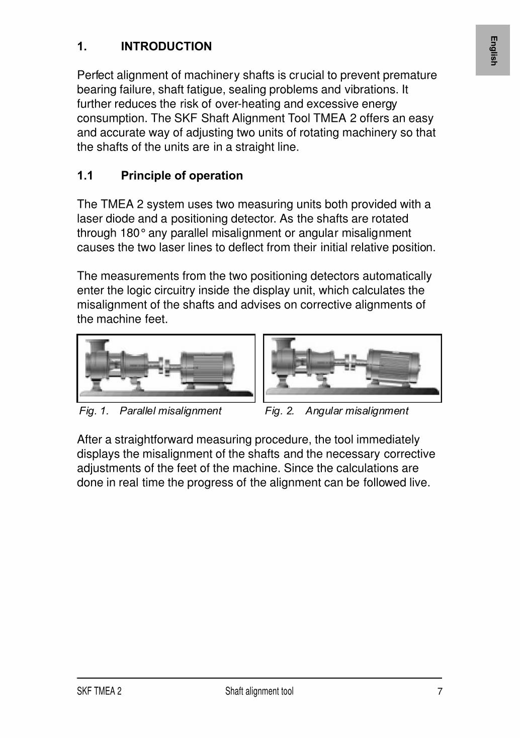
1.1 Principle of operation
The TMEA 2 system uses two measuring units both provided with a
laser diode and a positioning detector. As the shafts are rotated
through 180° any parallel misalignment or angular misalignment
causes the two laser lines to deflect from their initial relative position.
The measurements from the two positioning detectors automatically
enter the logic circuitry inside the display unit, which calculates the
misalignment of the shafts and advises on corrective alignments of
the machine feet.
After a straightforward measuring procedure, the tool immediately
displays the misalignment of the shafts and the necessary correctiveadjustments of the feet of the machine. Since the calculations are
done in real time the progress of the alignment can be followed live.
Fig. 2. Angular misalignment Fig. 1. Parallel misalignment

8 Shaft alignment tool SKF TMEA 2
1.2 Machine configuration
During the alignment procedure we will refer to the part of the
machinery which will be adjusted as the "Movable machine". The
other part we will refer to as the "Stationary machine".
1.3 Measuring positions
To define the various measuring positions during the alignmentprocedure we use the analogy of a clock as viewed from behind the
Movable machine. The position with the measuring units in an upright
position is defined as 12 o'clock while 90° left or right is defined as
9 and 3 o'clock.
Fig. 3. Stationary and Movable machine
Fig. 4. The analogy of a clock
A Stationary
B Movable
C Movable machine
A
B
C
F1
F2

E n gl i sh
SKF TMEA 2 Shaft alignment tool 9
2. SHAFT ALIGNMENT TOOL
The following components are included with the TMEA 2 tools:
• Display unit
• 2 measuring units with spirit levels
• 2 magnetic / mechanical shaft fixtures
• 2 locking chains
• 5 sets of shims
• Measuring tape• Instructions for use
• Set of alignment reports
• Carrying case
Fig. 5. Tool components

10 Shaft alignment tool SKF TMEA 2
Details of the display unit and the mechanical fixture with measuring
unit can be seen on figures 6 and 7.
A Connector for measuring unit on
Stationary machine
B Connector for measuring unit on
Movable machine
C LCD Display
D ON/OFF button
E Increase (+) button
F Next button
G Previous button
H Decrease (-) button
J Machine dimensions (A,B and
C) / Measured values (S and M)
K Rear feet values
L Front feet values
M Indication of parallel coupling
value direction
N Indication of angular coupling
value direction
P Position (9/12/3 o'clock) of
measuring units
R Low battery
S Imperial or metric units
Fig. 6. Display unit
A B
C
D
E
FGH
J
K
L
M
N
PR
S

E n gl i sh
SKF TMEA 2 Shaft alignment tool 11
A Position sensor detector
B Spirit level
C Wheel for vertical fine
adjustment of laser line
D Warning LED
E Chain fixation screw
F Locking chain
G Magnetic / mechanical fixture
H Connection rod
J Release / tightening knob
Fig. 7. Magnetic / Mechanical fixture with measuring unit
A
B
C
D
E
F
G
H
J

12 Shaft alignment tool SKF TMEA 2
2.1 Technical data
Denotation 1 mil = 1 thousandth of an inch
Measuring units
Housing material ABS plastic
Type of laser Diode laser
Laser wave length 670 - 675 nm
Laser class 2
Maximum laser power 1 mW
Maximum distance betweenmeasuring units (measured betweenfixture center line) 850 mm (2.8 ft)
Minimum distance betweenmeasuring units (measured betweenfixture center line) 70 mm (2.7 in)
Type of detectors Single-axis PSD, 8.5 x 0.9 mm(0.3 x 0.04 in)
Cable length 1.6 m (5.2 ft)
Dimensions 87 x 79 x 39 mm (3.4 x 3.1 x 1.5 in)
Weight 210 gram (7.3 oz)
Display unit
Housing material ABS plastic
Display type LCD 35 x 48 mm (1.4 x 1.9 in)
Battery type 2 x 1.5V LR14 Alkaline
Operating time 20 hours continuous operating
Auto power off after 1 hour if no keys are pressed
Displayed resolution 0.01 mm (0.1 mil with "inch" setting)
Dimensions 230 x 81 x 62 mm (9.1 x 3.2 x 2.4 in)
Weight 300 g (10.5 oz)
Shims
Size 50 x 50 mm (2.0 x 2.0 in)
Thickness 0.05 - 0.10 - 0.25 - 0.50 - 1.00 mm(1.96 - 3.93 - 9.84 - 19.68 -39.37 mils)
Slot width 13 mm (0.51 in)
Complete system
Shaft diameter range 30-500 mm (1.2 - 20 in)
Magnetic 30 - 500 mm (1.2 - 20 in)
Chain 30 - 150 mm (1.2 - 5.9 in)
Optional chain 150 - 500 mm (5.9 - 20 in)
Accuracy of system <2% +/-0.01mm
Temperature range 0-40 °C (32 - 104 °F)
Operating humidity < 90%
Carrying case dimensions 390 x 340 x 95 (15.4 x 13.4 x 3.7 in)
Total weight (incl. case) 3.7 kg (8.1 lb)
Calibration certificate valid for two years
Warranty 12 months

E n gl i sh
SKF TMEA 2 Shaft alignment tool 13
3. INSTRUCTIONS FOR USE
3.1 Measurement units
Metric or imperial sizes
The tool is delivered with a pre-selection for measurements in mm.
In case you want to change into inches, press the minus sign
simultaneously to switching the tool on. To revert back to mm press
the plus sign when switching on. The last setting will always beremembered.
3.2 Feet on the ground
If there is any doubt whether the machine is resting equally on all feet
please check for so called "soft foot". The procedure for this operation
is described in chapter 3.10.

14 Shaft alignment tool SKF TMEA 2
3.3 Attachment of measuring units
a) Use the magnetic fixtures to attach the measuring units to the
shafts. If the shafts are in good condition, only the magnetic
fixture is required. When using the magnetic fixture always try to
place it on the shaft and press it against the coupling. If the shafts
are not in good condition or if the fixtures are not sufficiently
secured to them, use the chains. Make sure that the M-marked
unit is attached to the Movable machine and the S-marked unit tothe Stationary machine. For diameters larger than 150 mm, if
chains are still needed an accessory extension chain (TMEA C2)
is required.
If it is not possible to attach the fixtures directly to the shafts (e.g. incase of space problems) the fixtures can be attached to the coupling.
Note!
It is highly recommended to position the measuring units at equal
distance from the middle of the coupling.
Fig. 8. Attachment of magnetic / mechanical fixture with chain

E n gl i sh
SKF TMEA 2 Shaft alignment tool 15
b) Connect the measuring units to the display unit. Make sure that
the marking on the cables corresponds to the marking of theports in the display unit (fig. 9).
3.4 Switch on
Switch on the display unit by pressing the ON/OFF button. You will
now be prompted to enter the machine dimensions as per
chapter 3.5. If no button is pressed within 60 minutes, the unit will turn
off automatically.
Fig. 9. Connection of the measuring units

16 Shaft alignment tool SKF TMEA 2
3.5 Machine dimensions
The configuration of the machinery is defined by three dimensions.
A: The distance between the two measuring units, as measured
between the fixture centre marks.
B: The distance between the M-marked measuring unit and the front
pair of feet of the Movable machine.
C: The distance between the front feet and the rear feet of the
Movable machine.
Fig. 10. Machine dimensions
A B C
E n gl i sh
SKF TMEA 2 Shaft alignment tool 17
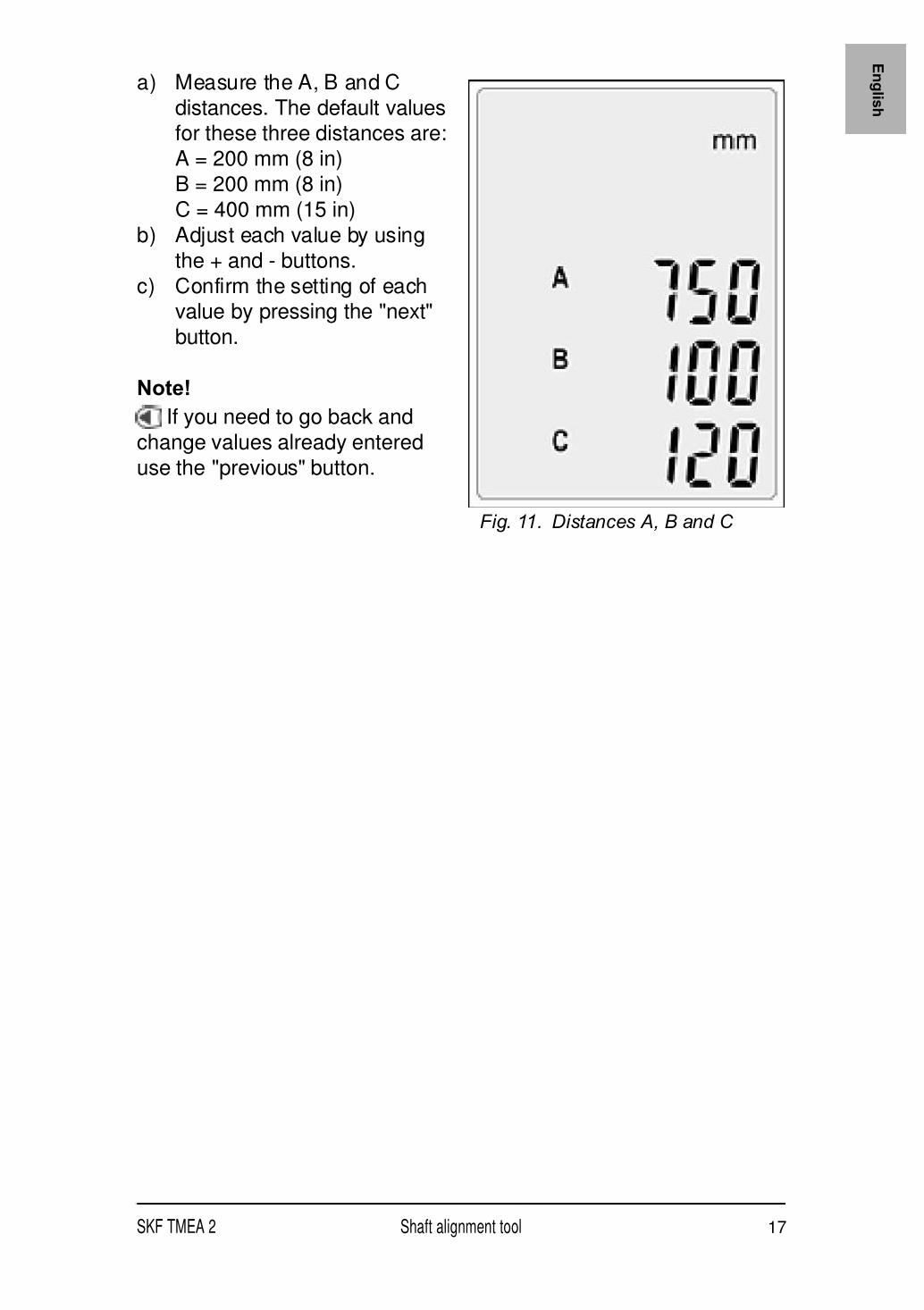
a) Measure the A, B and C
distances. The default valuesfor these three distances are:
A = 200 mm (8 in)
B = 200 mm (8 in)
C = 400 mm (15 in)
b) Adjust each value by using
the + and - buttons.
c) Confirm the setting of eachvalue by pressing the "next"
button.
Note!
If you need to go back and
change values already entered
use the "previous" button.
Fig. 11. Distances A, B and C

18 Shaft alignment tool SKF TMEA 2
3.6 Aiming the laser lines
a) Put the two measuring units in the 12 o'clock position with the
help of the spirit levels (fig. 12).
Fig. 12. The 12 o'clock position

E n gl i sh
SKF TMEA 2 Shaft alignment tool 19
b) Aim the laser lines so that they hit in the centre of the target of the
opposite measuring unit (fig. 13).
Fig. 13. Hit the target
A Laser line
A A

20 Shaft alignment tool SKF TMEA 2
c) For coarse adjustment release the measuring unit by unlocking
the knob on the side of the unit (fig. 14). This allows themeasuring unit to slide up and down the rod at the same time as it
can swivel freely. For the fine adjustment in height use the
adjustment wheels on the measuring units.
Fig. 14. Adjustment mechanism
A Vertical positioning of measuring unit
B Horizontal rotation of measuring unit
C Vertical fine adjustment of laser
A
B
C

E n gl i sh
SKF TMEA 2 Shaft alignment tool 21
e) If the horizontal alignment is very poor the laser lines might travel
outside the detector areas. If this happens a rough alignmentmust be done. Do this by aiming the laser lines at the positioning
detectors in the 9 o'clock position. Turn the measuring units to the
3 o'clock position when the lines will hit outside the detector
areas. Adjust the lines to the position half-way between the
detector centre and the actual position by means of the
adjustment mechanism as per fig. 15. Align the Movable machine
until the lines hit the centre of the positioning detector.
Fig. 15. Rough alignment
A The beam moves outside the detector area
B Adjust the beam to half the travel
C Direct the machine to hit the centre
A
B
C
22 Shaft alignment tool SKF TMEA 2
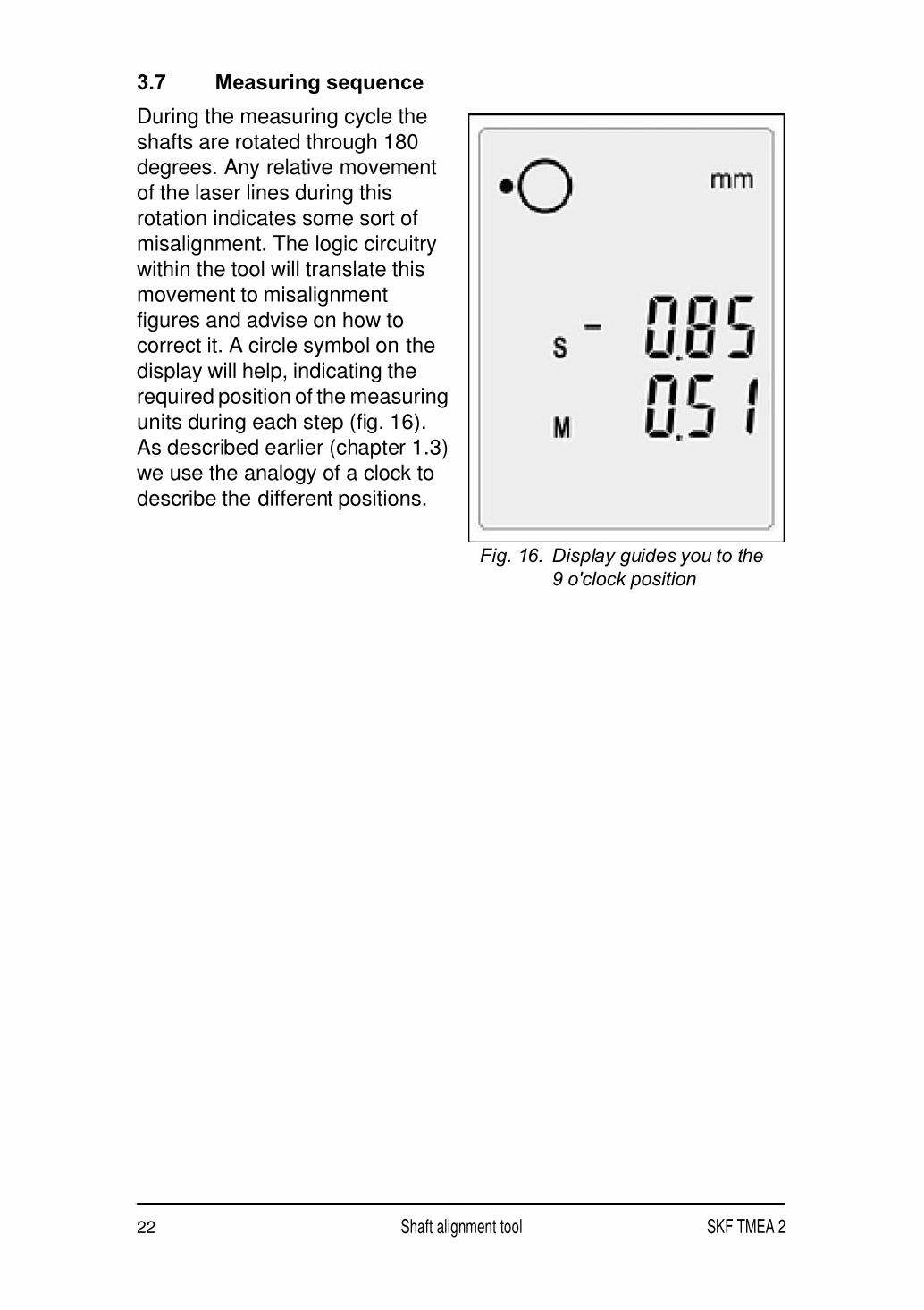
3.7 Measuring sequence
During the measuring cycle the
shafts are rotated through 180degrees. Any relative movement
of the laser lines during this
rotation indicates some sort of
misalignment. The logic circuitry
within the tool will translate this
movement to misalignment
figures and advise on how tocorrect it. A circle symbol on the
display will help, indicating the
required position of the measuring
units during each step (fig. 16).
As described earlier (chapter 1.3)
we use the analogy of a clock to
describe the different positions.
Fig. 16. Display guides you to the
9 o'clock position

E n gl i sh
SKF TMEA 2 Shaft alignment tool 23
a) Adjust the measuring units to
the 9 o'clock position with theaid of the spirit levels (fig. 17).
b) Confirm the measurement by
pressing .
c) Follow the circle symbol on
the display and rotate the
measuring units to the
3 o'clock position (fig. 18).
d) Confirm the measurement by
pressing .
Note!
By pressing the "previous"
button, you will reverse the
process in order to repeat any
of the measurement steps or
to adjust any of the machine
dimensions.
Fig. 17. Adjust to the 9 o'clock
position
Fig. 18. Rotate to the 3 o'clock
position

24 Shaft alignment tool SKF TMEA 2
3.8 Alignment results
3.8.1 Measured
misalignment
After the second measurement at
3 o'clock has been confirmed, the
misalignment of the two machines
in the measurement plane, the
plane where the measuring units
are (i.e. horizontal in this case) isdisplayed (fig. 19).
Coupling values
The coupling value on top of the
display shows the angle between
the centre lines of the two shafts
in the measurement plane(measured in mm/100 mm or
0.001"/1").
The value below on the display
shows the parallel off-set of the
two centre lines in the
measurement plane.
These two values are the coupling
values in the measurement plane.
Feet values
The values F1 and F2 on the display indicate the relative positions of
the Movable machine in the measurement plane.
The F1 value indicates the relative position of the front pair of feet of
the Movable machine.
The F2 value indicates the relative position of the rear pair of feet of
the Movable machine.
Fig. 19. Measured misalignment

E n gl i sh
SKF TMEA 2 Shaft alignment tool 25
3.8.2 Vertical alignment
Adjust the measuring units to the
12 o'clock position (fig. 20) with
the aid of the spirit levels
Observe the coupling and feet
values live adjustment.
The machine misalignment should always be within themanufacturer's specified tolerances. In case such tolerances are
missing table 1 can be used as a rough guide-line.
Fig. 20. The 12 o'clock position
Table 1. Acceptable maximum misalignment
rpm mm/100 mm 0.001”/1” mm 0.001”
0 - 1000 0.10 1.0 0.13 5.1
1000 - 2000 0.08 0.8 0.10 3.9
2000 - 3000 0.07 0.7 0.07 2.8
3000 - 4000 0.06 0.6 0.05 2.0
4000 - 6000 0.05 0.5 0.03 1.2

26 Shaft alignment tool SKF TMEA 2
a) If the measured coupling
values are within thetolerances, the Movable
machine does not have to be
adjusted. Correct the
horizontal misalignment.
Continue to chapter 3.8.3
Horizontal alignment.
b) If the measured coupling
values are higher than the
acceptable tolerances check
the recommended corrections
of the feet.
The F1 and F2 values on the
display indicate the relative
positions of the Movable machine
when viewed from the side
(fig. 21).
A positive value means that the
feet are too high and need to be
lowered while a negative valuemeans the opposite (fig. 22).
Loosen the feet of the movable
machine.
Use the shims included with the
tool to adjust the height of themachine. Observe the coupling
and feet values live adjustment.
After having carried out the
vertical alignment proceed to the
horizontal alignment
(chapter 3.8.3).
Fig. 21. Display vertical alignment
Fig. 22. Vertical alignment

E n gl i sh
SKF TMEA 2 Shaft alignment tool 27
3.8.3 Horizontal alignment
Move the measuring units to the
3 o'clock position (fig. 23).
Observe the coupling and feet
values live adjustment.
Machine misalignment should be
within the manufacturer's
specified tolerances. In case such
tolerances are missing, table 1can again be used as a general
recommendation.
a) If the measured coupling
values are within the
tolerances, no sideways
adjustment is necessary.b) If the measured coupling
values are higher than the
acceptable tolerances check
the recommended correction
on the feet.
Fig. 23. The 3 o'clock position
Fig. 24. Horizontal alignment

28 Shaft alignment tool SKF TMEA 2
The F1 and F2 values indicated
on the display give the relativepositions of the Movable machine
when viewed from above (fig. 25).
The F1 value for the front pair of
feet, the F2 value is for the rear
pair of feet.
The alignment values indicate thenecessary corrective sideways
movement of the Movable
machine (when viewed from
behind the Movable machine).
A negative value means that the
feet have to be moved to the right.
A positive value means that thefeet have to be moved to the left
(fig. 26).
Observe the coupling and feet
values live adjustment while
moving the movable machine
sideways.
The alignment is complete.
Tighten the feet of the movable
machine.
3.9 Verify alignment
To verify the alignment of the machinery, it is recommended to
execute the measuring procedure once again. To do so, go back by
using the previous button until you reach the first measuring step
(9 o'clock position) and continue as per chapter 3.7.
Fig. 25. Display horizontal
alignment
Fig. 26. Horizontal alignment

E n gl i sh
SKF TMEA 2 Shaft alignment tool 29
This page has been intentionally left blank.

30 Shaft alignment tool SKF TMEA 2
3.10 Soft foot
Before starting the alignment it is
recommended to check theMovable machine for soft foot.
"Soft foot" is the expression used
when a machine is not resting
equally on all feet.
To find and correct the soft foot do
as follows:1. Tighten all bolts.
2. Execute all preparation steps
as per chapter 3.1 to 3.6.
3. Press + and - simultaniously
to reach the soft foot mode.The text "soft foot" should
now be visible on the screen
as shown on the figure 28.
4. Position the measuring units
in the 12 o'clock position.
5. Press Next to zero the display
values.
Fig. 27. Soft foot
A Soft foot
A
Fig. 28. Soft foot display

E n gl i sh
SKF TMEA 2 Shaft alignment tool 31
6. Loosen one of the bolts and monitor the change of the displayed
values.• If the deviations are less than 0.05 mm (2 mils), the foot has a
good support. Tighten the bolt and go to the next foot.
• If any of the deviations is larger than 0.05 mm (2 mils), the foot
or its diagonally opposed foot is a soft foot. Tighten the bolt
and check the diagonally opposed foot.
• If the deviation is larger than the previously tightened foot,
then this is the soft foot.• If not, tighten the bolt and go back to the previous diagonally
opposed foot. It is normally worthwhile to try to improve the
support of the soft foot by adding shims. Add the amount of
shims corresponding to the larger deviation measured.
7. Tighten and loosen the bolt once again to check that the deviation
does not exceed 0.05 mm (2 mils).
8. Repeat steps 5 to 8 for the remaining feet. The soft foot is nowchecked and corrected.
9. Press + and - simultaniously to leave the soft foot mode and enter
the measuring sequence.

32 Shaft alignment tool SKF TMEA 2
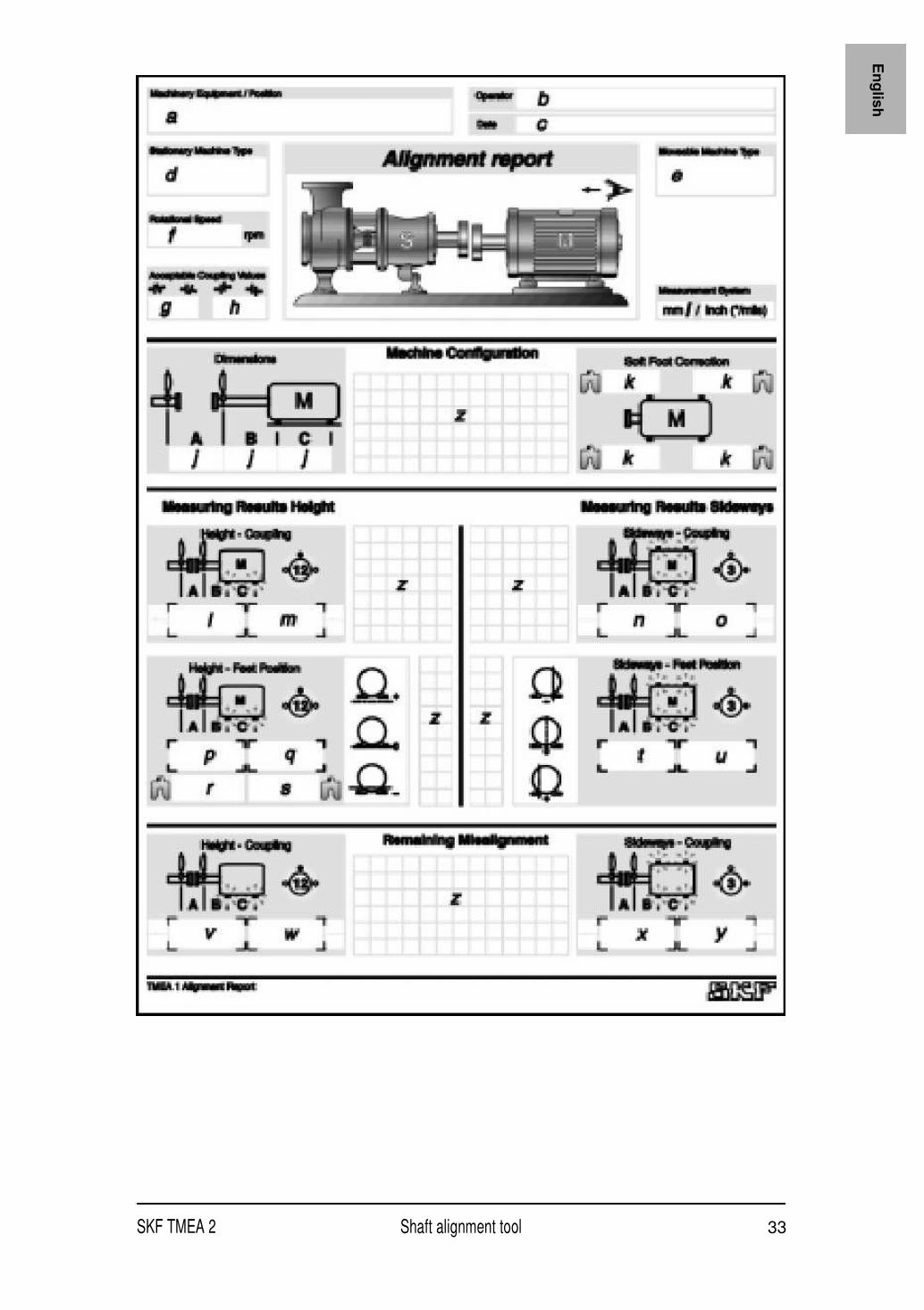
4. ALIGNMENT REPORT
In order to facilitate recording of the alignment operation, the TMEA 2
is provided with a set of alignment reports.
The report contains the following data fields:
a) Name of the equipment
b) Name of the operator
c) Date
d) Name and/or reference of Stationary machinee) Name and/or reference of Movable machine
f) Maximum rotational speed
g) Maximum acceptable angle between centre lines of the shafts
h) Maximum acceptable off-set of centre lines
i) Selection of metric or imperial dimensions
j) Machine configuration; distances A, B and C
k) Soft foot correction donel) Vertical alignment: resulting angular error
m) Vertical alignment: resulting parallel offset
n) Horizontal alignment: resulting angular error
o) Horizontal alignment: resulting parallel offset
p) Vertical alignment: resulting height position of the front feet
q) Vertical alignment: resulting height position of the rear feet
r) Height of shims to be added or removed under front feet(excluding soft foot correction)
s) Height of shims to be added or removed under rear feet
(excluding soft foot correction)
t) Horizontal alignment: resulting sideways position of the front feet
u) Horizontal alignment: resulting sideways position of rear feet
v) Remaining vertical anglew) Remaining vertical off-set
x) Remaining horizontal angle
y) Remaining horizontal off-set
z) Space for own notes
E n gl i sh
SKF TMEA 2 Shaft alignment tool 33
34 Shaft alignment tool SKF TMEA 2
5. ADVANCED USE
5.1 Limited rotation
In some applications, limited space around the shaft coupling forbids
the rotation of the measuring units to the 9 or 3 o'clock position.
However, it is still possible to perform the alignment as long as the
measuring units can rotate 180°.
Execute all preparation steps as per chapter 3.1 to 3.6.
Measuring sequence:
1. The display unit indicates that the measuring units should be
placed in the 9 o'clock position. Since you can't reach it, place the
measuring units in your start position (in our example 11 o'clock)
and confirm the measurement by pressing the "next" button: .
2. The display unit now indicates the measuring units should be
placed in the 3 o'clock position. Rotate the measuring units by
180° (in our example to the 5 o'clock position) and confirm the
measurement: .
3. You can now complete the alignment following the instructionssequence as per chapter 3.8.
5.2 Trouble shooting
5.2.1 The system does not switch on
a) Check that batteries are inserted in the right way.
b) Replace the batteries. Use principally Alkaline batteries for a
better life span.
5.2.2 No laser lines
a) Make sure that the display unit is switched ON.b) Check the cables and connectors. Assure that all cables are
properly connected.
c) Check to see if the measuring units' warning LEDs flash.
d) Replace the batteries.

E n gl i sh
SKF TMEA 2 Shaft alignment tool 35
5.2.3 No measurement values
a) Check the cables and connectors.
b) Assure that the laser lines hit the positioning detectors.
c) Assure uninterrupted travel of the laser lines.
5.2.4 Fluctuating measurement values
a) Assure tight attachment of fixtures and measuring units.
b) Assure that the laser lines hit the detectors.
c) Assure that air turbulence does not influence the measurement.
d) Assure that direct bright light or obstructed laser lines do notinfluence the measurement results.
e) Assure that external extensive vibrations do not influence the
measurement.
f) Assure that radio communications (like walkie-talkies) do not
influence the measurement.
5.2.5 Incorrect measuring results
a) Assure you face the Stationary machine from behind the Movable
machine.b) Check the attachment of fixtures and measuring units.
c) S-cable to S-unit and M-cable to M-unit?
d) S-unit on Stationary and M-unit on Movable machine?
e) Assure right position before confirmation of measurements.
5.2.6 Measurement results cannot be repeated
a) Check if there is a soft foot condition.
b) Check if there are any loose mechanical parts, play in bearing or
movements in the machinery.
c) Check the status of foundation, base plate, bolts and existing
shims.

36 Shaft alignment tool SKF TMEA 2
6. MAINTENANCE
6.1 Handle with care
The measuring units are equipped with sensitive electronic and
optical parts. Handle them with care.
6.2 Cleanliness
For best function the system should be kept clean. The optics near
the laser and detector should be free of finger prints. If necessary
clean with cotton cloth.
6.3 Batteries of the display unit
The display unit is powered by two LR14 (C) batteries. Most LR14 (C)batteries can be used, but Alkaline batteries have the longest life. If
not using the system for a long period, remove the batteries from the
display unit. Flat batteries will be indicated by the battery signal on the
display.
6.4 Replacement of measuring units or display unit
Both measuring units are calibrated in pairs and hence they must be
replaced as a pair.