Sketches and Working Drawings Sketches are freehand drawings of an object for a project done in...
22
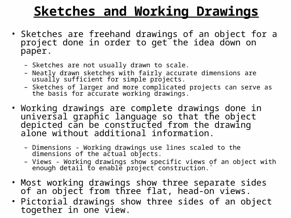
Sketches and Working Drawings • Sketches are freehand drawings of an object for a project done in order to get the idea down on paper. – Sketches are not usually drawn to scale. – Neatly drawn sketches with fairly accurate dimensions are usually sufficient for simple projects. – Sketches of larger and more complicated projects can serve as the basis for accurate working drawings. • Working drawings are complete drawings done in universal graphic language so that the object depicted can be constructed from the drawing alone without additional information. – Dimensions - Working drawings use lines scaled to the dimensions of the actual objects. – Views - Working drawings show specific views of an object with enough detail to enable project construction.` • Most working drawings show three separate sides of an object from three flat, head-on views. • Pictorial drawings show three sides of an object together in one view.
-
Upload
mireya-crowell -
Category
Documents
-
view
217 -
download
2
Transcript of Sketches and Working Drawings Sketches are freehand drawings of an object for a project done in...
Sketches and Working Drawings
• Sketches are freehand drawings of an object for a project done in order to get the idea down on paper.
– Sketches are not usually drawn to scale.– Neatly drawn sketches with fairly accurate dimensions are usually sufficient
for simple projects.– Sketches of larger and more complicated projects can serve as the basis for
accurate working drawings.
• Working drawings are complete drawings done in universal graphic language so that the object depicted can be constructed from the drawing alone without additional information.
– Dimensions - Working drawings use lines scaled to the dimensions of the actual objects.
– Views - Working drawings show specific views of an object with enough detail to enable project construction.`
• Most working drawings show three separate sides of an object from three flat, head-on views.
• Pictorial drawings show three sides of an object together in one view.
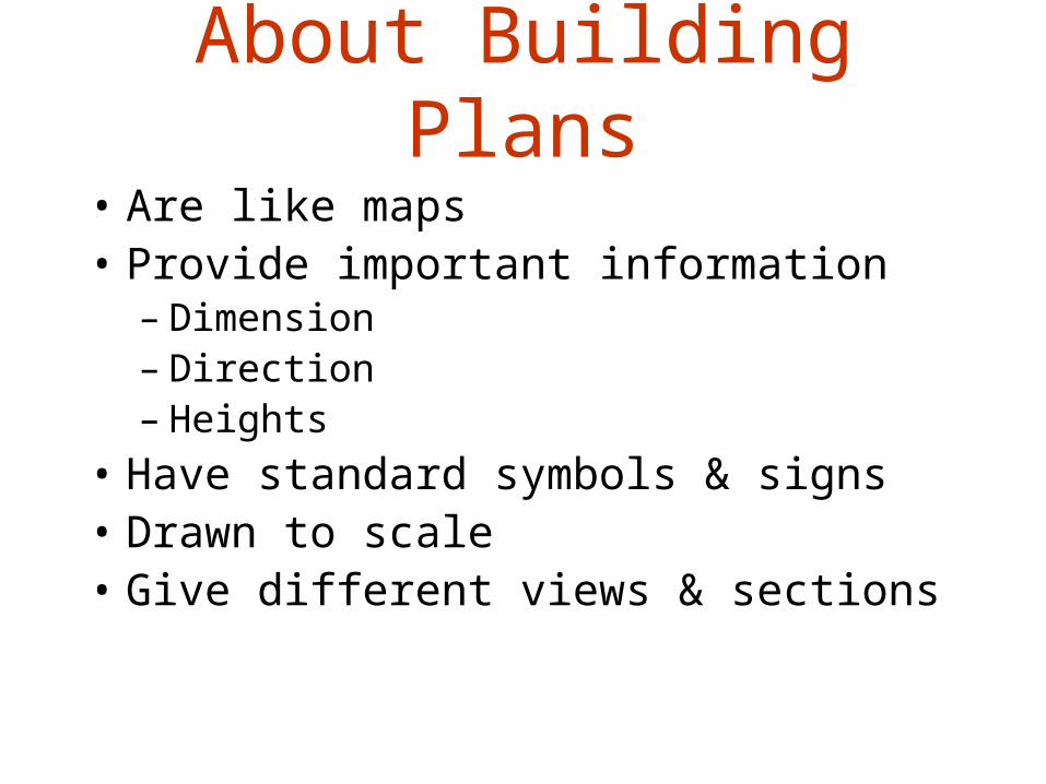
About Building Plans
• Are like maps• Provide important information
– Dimension– Direction– Heights
• Have standard symbols & signs• Drawn to scale• Give different views & sections
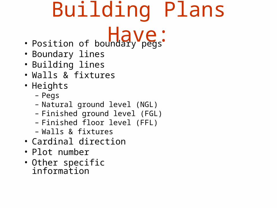
Building Plans Have:• Position of boundary pegs• Boundary lines• Building lines• Walls & fixtures• Heights
– Pegs– Natural ground level (NGL)– Finished ground level (FGL)– Finished floor level (FFL)– Walls & fixtures
• Cardinal direction• Plot number• Other specific information
Drawing to Scale
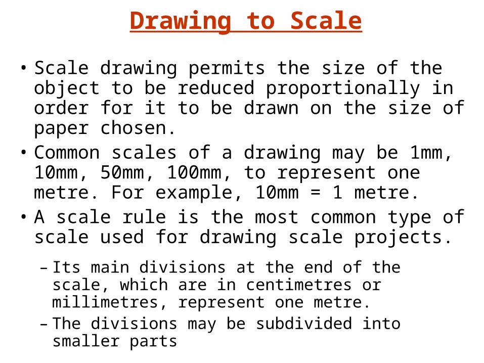
• Scale drawing permits the size of the object to be reduced proportionally in order for it to be drawn on the size of paper chosen.
• Common scales of a drawing may be 1mm, 10mm, 50mm, 100mm, to represent one metre. For example, 10mm = 1 metre.
• A scale rule is the most common type of scale used for drawing scale projects.
– Its main divisions at the end of the scale, which are in centimetres or millimetres, represent one metre.
– The divisions may be subdivided into smaller parts
Scale:
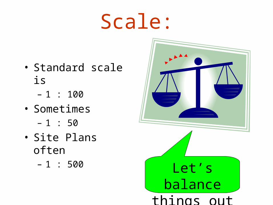
• Standard scale is– 1 : 100
• Sometimes– 1 : 50
• Site Plans often– 1 : 500
Let’s balance things out
Types of Lines Used in Drawings
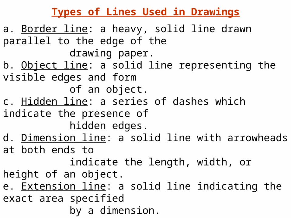
a. Border line: a heavy, solid line drawn parallel to the edge of the drawing paper.b. Object line: a solid line representing the visible edges and form of an object.c. Hidden line: a series of dashes which indicate the presence of hidden edges.d. Dimension line: a solid line with arrowheads at both ends to indicate the length, width, or height of an object.e. Extension line: a solid line indicating the exact area specified by a dimension.f. Break line: a solid, zigzag line which indicates that part of the object being drawn is not fully illustrated or has been left out.g. Center line: a long-short-long line used to depict the center of a round object.h. Leader line: a solid line with an arrow pointing from an explanatory note to a specific feature of an object.
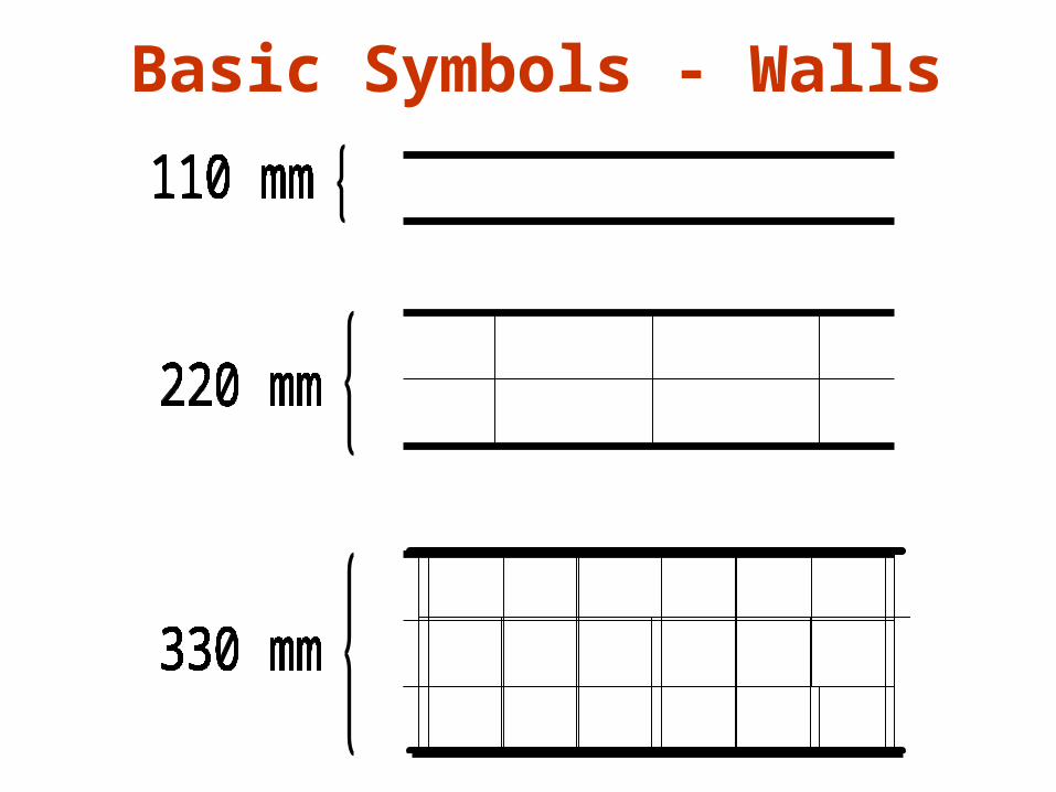
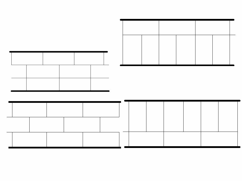
Basic Symbols - Walls
Windows
Doors
Showers
Kitchen Sink
STANDARD SIZES
900mm, 1200mm, 1500mm, 1800mm, 2100 mm
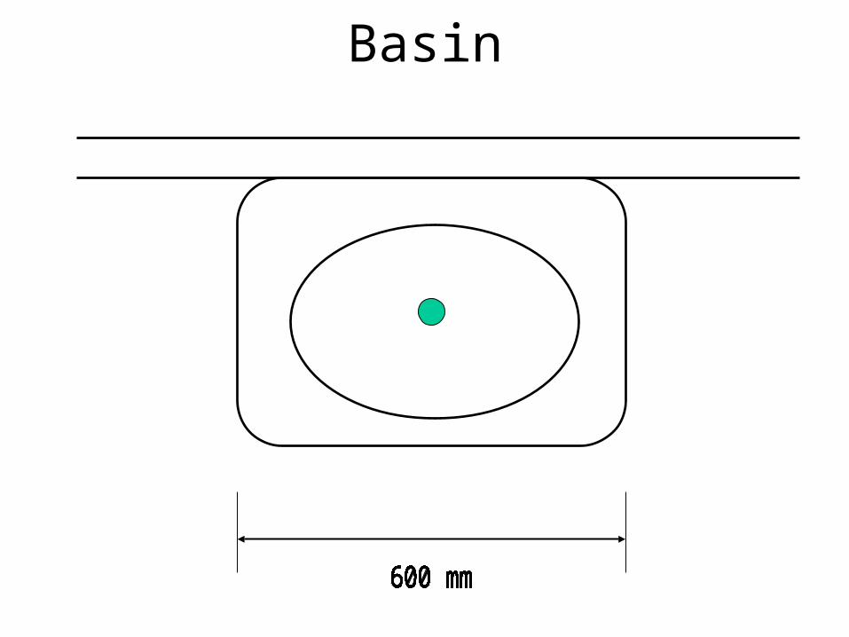
Basin
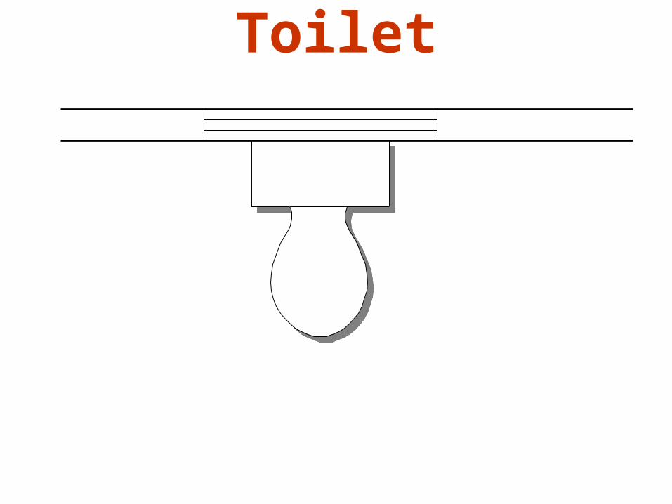
Toilet
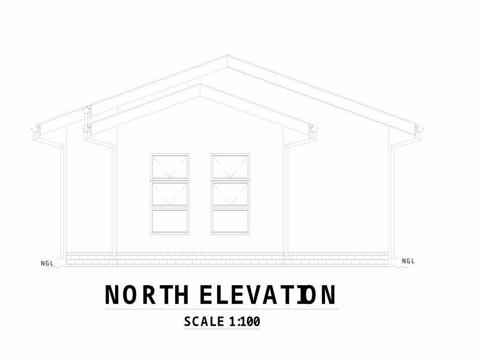
NORTH ELEVATIONSCALE 1:100
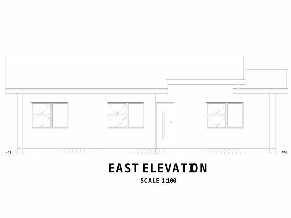
EAST ELEVATIONSCALE 1:100
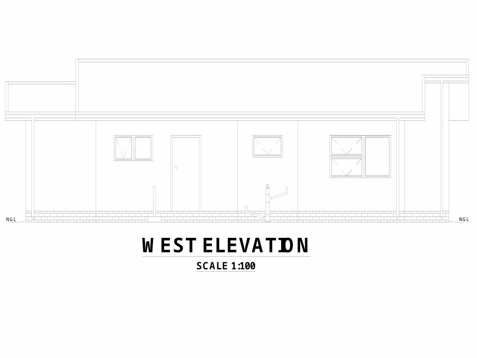
WEST ELEVATIONSCALE 1:100
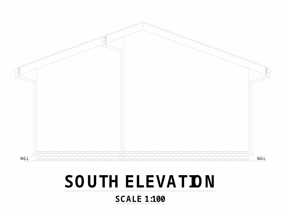
SOUTH ELEVATIONSCALE 1:100
NGLNGL NGL NGL
NGL NGL NGL NGL
NORTH ELEVATIONSCALE 1:100
EAST ELEVATIONSCALE 1:100
WEST ELEVATIONSCALE 1:100
SOUTH ELEVATIONSCALE 1:100
NGLNGL NGL NGL
NGL NGL NGL NGL
NORTH ELEVATIONSCALE 1:100
EAST ELEVATIONSCALE 1:100
WEST ELEVATIONSCALE 1:100
SOUTH ELEVATIONSCALE 1:100
NGLNGL NGL NGL
NGL NGL NGL NGL
NORTH ELEVATIONSCALE 1:100
EAST ELEVATIONSCALE 1:100
WEST ELEVATIONSCALE 1:100
SOUTH ELEVATIONSCALE 1:100
NGLNGL NGL NGL
NGL NGL NGL NGL
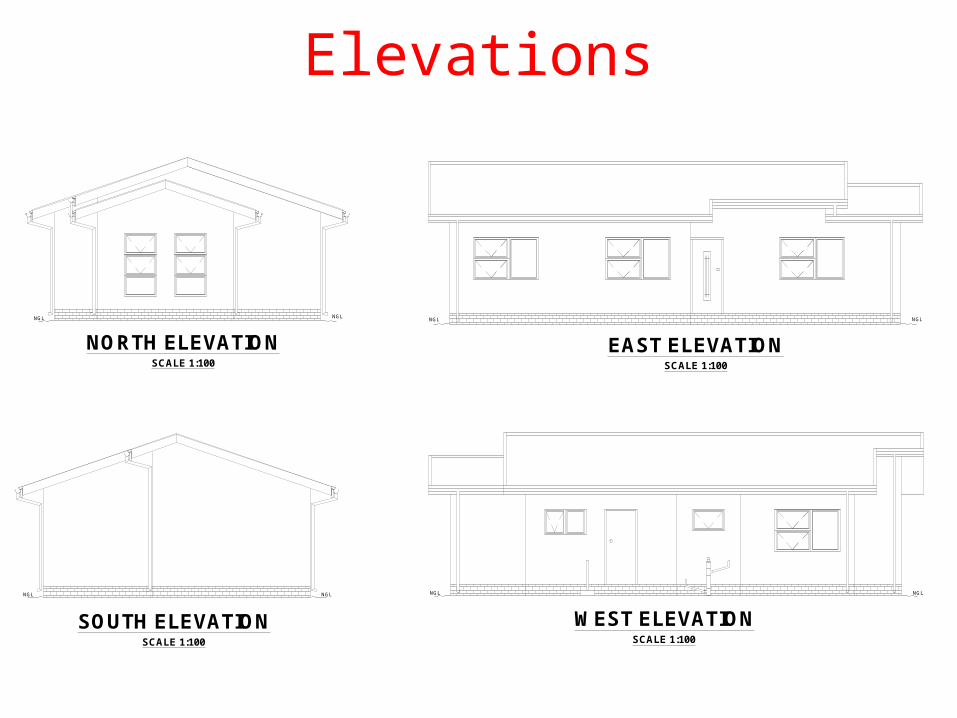
Elevations
NORTH ELEVATIONSCALE 1:100
EAST ELEVATIONSCALE 1:100
WEST ELEVATIONSCALE 1:100
SOUTH ELEVATIONSCALE 1:100
NGLNGL NGL NGL
NGL NGL NGL NGL
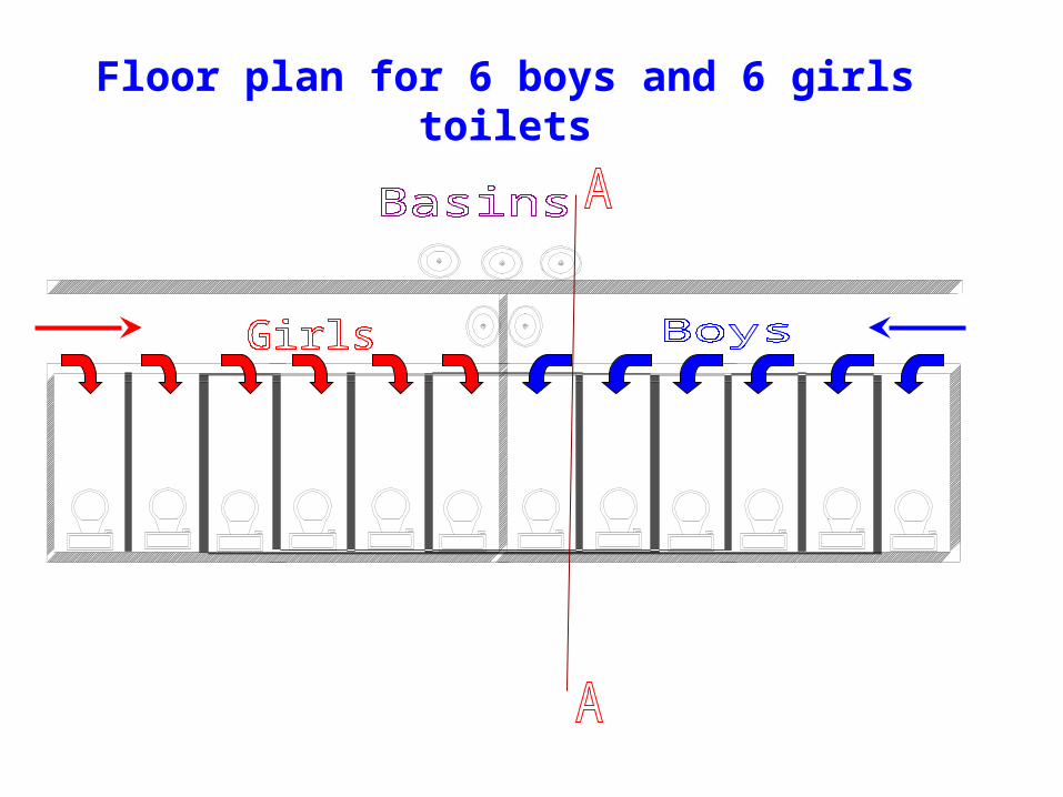
Floor plan for 6 boys and 6 girls toilets
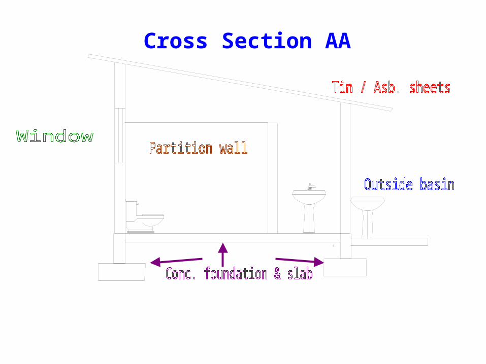
Cross Section AA
Compiled & developed by
V Govindsamy