Sketch-Based Search and Composition of 3D Modelsfunk/sbim08.pdf · Jeehyung Lee & Thomas Funkhouser...
8
EUROGRAPHICS Workshop on Sketch-Based Interfaces and Modeling (2008) C. Alvarado and M.- P. Cani (Editors) Sketch-Based Search and Composition of 3D Models Jeehyung Lee and Thomas Funkhouser Princeton University Abstract There is growing interest in developing tools with which novice users can create detailed 3D models of their own designs. The most popular approaches to this problem include sketch-based interfaces and part-composition systems. The sketch-based modeling systems provide natural interfaces for creating 3D models from 2D sketches, but are generally limited to creating simple geometric models. The part-composition systems provide tools for combining parts extracted from a database of 3D models, and thus can generate very detailed 3D models, but usually with much higher overhead and expertise required by the user for manipulating 3D geometry interactively. In this paper, we introduce a new modeling method that overcomes these limitations by combining both approaches – we introduce a modeling system for parts composition with a sketching interface. The system allows the user to find a part in a database and composite it into a model with a single sketch. This approach combines the benefits of both approaches – i.e., it allows creation of highly detailed models/scenes (as details come from parts in the database), while 2D sketched strokes provide all the information for part selection and composition (no 3D manipulation is required, in general). To enable this modeling method, we investigate an algorithm for 3D shape search with 2D sketch as a shape query and a part placement algorithm which automatically orients, translates, scales, and attaches a new part into a modeling scene by taking the user sketch as a hint. User experiences with our prototype system show that novice users can create interesting and detailed models with our system. Categories and Subject Descriptors (according to ACM CCS): I.3.6 [Interaction techniques]: sketch-based modeling. 1. Introduction The development of easy-to-use systems for creation of 3D models is one of the most important research areas in mod- ern computer graphics. While demand for 3D models has been greatly increasing over the last few years, 3D surface modeling remains difficult for most people, as commercial modeling systems generally require technical expertise and artistic skill. Many efforts have been made to simplify the process of 3D modeling. One major approach is to provide sketch based interfaces [ZPF96, IMT99] which allow users to draw 2D sketches and infer simple 3D shapes from those sketches. Another popular approach is to provide tools for composi- tion of parts from existing 3D models [FKS * 04, SCoL * 04]. While these approaches have greatly simplified the 3D mod- eling process, there are also limitations. Sketch based sys- tems are natural and easy to learn, but limited to designing simple shapes. Part composition systems can construct de- tailed, complex models, but often require cumbersome ge- ometric operations to construct similarity queries, place re- trieved parts in the desired coordinate frames, and fuse parts together. In this paper, we describe a sketch-based modeling sys- tem for composition of 3D parts. Unlike most previous systems, sketched strokes are interpreted both as similarity queries into a database of 3D parts and as alignment cues for placement and composition of parts into a scene (Figure 1). Specifically, for each modeling operation: (1) The user first sketches an outline of the part he/she wants to include in the scene at the place where it should be loaded. (2) The system takes the sketch as a shape query, performs a shape search on a given parts database, and shows the user the search re- sult. (3) The user then selects a part he likes best from the search result. Finally, (4) The system determines the selected part’s geometrical relationship with the rest of the modeling scene by taking the user sketch as a hint and automatically orients, translates, scales, and attaches the part into the mod- eling scene. c The Eurographics Association 2008.
Transcript of Sketch-Based Search and Composition of 3D Modelsfunk/sbim08.pdf · Jeehyung Lee & Thomas Funkhouser...

EUROGRAPHICS Workshop on Sketch-Based Interfaces and Modeling (2008)C. Alvarado and M.- P. Cani (Editors)
Sketch-Based Search and Composition of 3D Models
Jeehyung Lee and Thomas Funkhouser
Princeton University
Abstract
There is growing interest in developing tools with which novice users can create detailed 3D models of theirown designs. The most popular approaches to this problem include sketch-based interfaces and part-compositionsystems. The sketch-based modeling systems provide natural interfaces for creating 3D models from 2D sketches,but are generally limited to creating simple geometric models. The part-composition systems provide tools forcombining parts extracted from a database of 3D models, and thus can generate very detailed 3D models, butusually with much higher overhead and expertise required by the user for manipulating 3D geometry interactively.In this paper, we introduce a new modeling method that overcomes these limitations by combining both approaches– we introduce a modeling system for parts composition with a sketching interface. The system allows the userto find a part in a database and composite it into a model with a single sketch. This approach combines thebenefits of both approaches – i.e., it allows creation of highly detailed models/scenes (as details come from partsin the database), while 2D sketched strokes provide all the information for part selection and composition (no 3Dmanipulation is required, in general). To enable this modeling method, we investigate an algorithm for 3D shapesearch with 2D sketch as a shape query and a part placement algorithm which automatically orients, translates,scales, and attaches a new part into a modeling scene by taking the user sketch as a hint. User experiences withour prototype system show that novice users can create interesting and detailed models with our system.
Categories and Subject Descriptors (according to ACM CCS): I.3.6 [Interaction techniques]: sketch-based modeling.
1. Introduction
The development of easy-to-use systems for creation of 3Dmodels is one of the most important research areas in mod-ern computer graphics. While demand for 3D models hasbeen greatly increasing over the last few years, 3D surfacemodeling remains difficult for most people, as commercialmodeling systems generally require technical expertise andartistic skill.
Many efforts have been made to simplify the process of3D modeling. One major approach is to provide sketch basedinterfaces [ZPF96, IMT99] which allow users to draw 2Dsketches and infer simple 3D shapes from those sketches.Another popular approach is to provide tools for composi-tion of parts from existing 3D models [FKS∗04, SCoL∗04].While these approaches have greatly simplified the 3D mod-eling process, there are also limitations. Sketch based sys-tems are natural and easy to learn, but limited to designingsimple shapes. Part composition systems can construct de-tailed, complex models, but often require cumbersome ge-
ometric operations to construct similarity queries, place re-trieved parts in the desired coordinate frames, and fuse partstogether.
In this paper, we describe a sketch-based modeling sys-tem for composition of 3D parts. Unlike most previoussystems, sketched strokes are interpreted both as similarityqueries into a database of 3D parts and as alignment cues forplacement and composition of parts into a scene (Figure 1).Specifically, for each modeling operation: (1) The user firstsketches an outline of the part he/she wants to include in thescene at the place where it should be loaded. (2) The systemtakes the sketch as a shape query, performs a shape searchon a given parts database, and shows the user the search re-sult. (3) The user then selects a part he likes best from thesearch result. Finally, (4) The system determines the selectedpart’s geometrical relationship with the rest of the modelingscene by taking the user sketch as a hint and automaticallyorients, translates, scales, and attaches the part into the mod-eling scene.
c© The Eurographics Association 2008.

Jeehyung Lee & Thomas Funkhouser / Sketch-Based Search and Composition of 3D Models
Figure 1: Modeling example using our prototype system
Our system combines the advantages of sketching withthose of composition. On the one hand, the system is easy tolearn and intuitive to use (simply sketch an outline of whatyou want, where you want it). On the other hand, it sup-ports creation of detailed, complex models (all the details ofmodels used are included in the final model). This synergysignificantly lowers the technical threshold to create inter-esting 3D models. It is suitable for designing new instancesof most man-made objects (vehicles, furniture, etc.), manytypes of natural objects (animals, people, etc), and scenescomposed of multiple objects (e.g., office scenes). As such,we believe that it is useful for a wide variety of applicationsranging from rapid prototyping for industrial designers toeducational purposes for children.
2. Related Work
Our modeling system combines concepts of sketch-basedmodeling, content-based retrieval, and 3D part composition.Here we review previous work that our system builds uponwithin these categories.
Sketch-Based Modeling: Our system is largely inspiredby the recent development of sketch-based modeling sys-tems and the trend towards building modeling tools fornovices. The motivating idea we share with previous work isto provide a simple and intuitive sketching method for cre-ating 3D models. However, the interpretation and use of 2Dsketches is quite different in our system than it is in pre-vious ones. Some systems interpret sketched strokes as pa-rameters for construction of geometric primitives [KQW06,YSv05, ZPF96]. Others interpret sketched input as con-tours [KH05,KH06] or displacements [BCCD04] that implyshape. Some use sketched outlines to infer the shape of acomplete, closed 3D surface [IMT99, IH03, NISA07], whileother systems use them as guidelines for local mesh defor-mation [ZNA07, NSACO05]. In contrast, our system inter-prets sketched lines as queries and placement guidelines forparts of 3D models retrieved from a database. The work mostrelevant to ours is Magic Canvas [SI07] system which usessketched lines in the same way to place 3D models in a scenewith limited orientations. However, this paper extends thatwork for design of general objects as well as scenes withlarger degrees of freedom.
Sketch-Based Retrieval: Our work utilizes many ideaspreviously proposed for retrieval of 3D models from adatabase based on similarity to 2D sketches drawn by auser. Several such systems exist, varying in the number andtype of sketches expected for each query, and how sketchesare matched to 3D models [FMK∗03, HR06, Lof00, JPR05].For example, the Princeton Search Engine expects outlinesketches for up to three views and matches them to pre-computed sketches for thirteen views of a 3D model us-ing Fourier descriptors of rendered images [FMK∗03]. ThePurdue search engine matches 2D views using 2.5D spher-ical harmonic descriptors, Fourier descriptors of boundarycontours, and Zernike moments of rendered images [HR07].SR-3DEditor matches sketches to outline contours with turn-ing functions and places retrieved models into the sameworking space [AS05]. However, these systems only allowretrieval of existing 3D models and provide no special fea-tures for composition of parts into new models.
3D Parts Composition: Our work is also inspired by re-cent work towards building 3D models by composition ofparts [FKS∗04, KJS07, LJW06, ONI06, SBSC06]. The gen-eral philosophy is to gather a large database of 3D modelsand then to provide methods to cut and composite them tocreate new, interesting models. For example, Shuffler findsa consistent segmentation of parts across several exampleswithin a class of objects and provides an easy interface forexchange of corresponding parts [KJS07]. Modeling by Ex-ample [FKS∗04] provides interactive methods for cutting3D models into parts, searching a database for similar parts,aligning parts, and attaching them across open boundaries.However, these systems do not provide good easy ways toconstruct queries for new parts. In Modeling by Example,for example, the user must construct a coarse 3D model outof boxes to represent the shape for a query into the database.Our main contribution is to augment such systems with ideasfrom sketch-based querying and modeling.
3. Overview
Our system is based on Modeling by Example(MBE) [FKS∗04]. It supports all the features of theoriginal system, including intelligent scissoring of 3Dmeshes, 3D shape similarity search for retrieving 3Dmeshes, and stitching/blending for composition of 3Dmeshes. It augments those features with a new sketch-basedinterface and new algorithms to make search, placement,and composition easier and more automatic.
Since the main design goal of our system is to providea sketch-based modeling interface that can be learned by anovice user within minutes, we ask the user to understandonly one type of modeling command entered with a single2D stroke: “find a part in the database whose outline hasa shape similar to my stroke and place it onto a surface ofthe current scene so that it matches the position, size, andorientation of the stroke as best as possible.” (Figure 1).
c© The Eurographics Association 2008.

Jeehyung Lee & Thomas Funkhouser / Sketch-Based Search and Composition of 3D Models
Of course, supporting such a command is challenging, asthe type, placement, and attachment of a new part must allbe inferred from a single 2D sketch. This is a grossly under-constrained problem, and thus we must provide optimizationalgorithms to find a solution that best matches the user’s in-put. Since these algorithms are not always perfect, we alsomust provide simple selection and undo commands to reviseand reverse the proposed solutions quickly and easily.
In our system, processing of each sketch-based modelingcommand proceeds as shown in Figure 2. When the userdraws an editing stroke, the system feeds the 2D contour asa shape-based query to 3D search engine which comparesthe shape of the contour to the outlines of all parts in thedatabase using 2D image to 3D shape matching algorithm(Section 4). The system generates a ranked list of the bestmatching parts and displays them as a list from which theuser selects a part. Then, the user’s 2D sketch, the selectedpart, and the current scene are fed into an optimization algo-rithm that produces a best transformation for the part so thatits outline fits the user’s stroke while connecting as best aspossible to the existing surfaces of the current scene (Sec-tion 5). If the part has a open boundary contour that couldbe attached topologically to the current scene, a hole is cutinto the meshes for the scene, and the meshes are stitchedand blended together across the resulting boundary contours(Section 6).
Figure 2: Steps performed for each modeling operation.
In the following sections, we describe our implementa-tions for the main steps of this process: (1) retrieving partsfrom a database to match a single 2D sketch, (2) placing re-trieved parts into a scene to match constraints provided bythe 2D sketches and 3D surfaces, and (3) topologically at-taching disjoint parts while blending across the seams.
4. Part Search
The first step is to retrieve parts from a database of 3D polyg-onal models matching a single sketch by a novice user. Ourassumption is that the user draws an approximation to the
Figure 3: Example boundary contour images of a car body.
boundary contour of a desired 3D part as seen from the cur-rent view. Thus, our goal is to search the database to find apart such that the projected boundary contour of the part forsome view best matches the user’s stroke in screen-space.
Like many prior systems [FMK∗03,HR06,Lof00,JPR05],we leverage preprocessing of the 3D model database to sim-plify and accelerate the matching process. First, we extractindividual parts from 3D models using automatic mesh seg-mentation algorithms, scene graph decompositions, and/orinteractive segmentation tools [FKS∗04]. Second, we alignthe parts in a canonical 3D coordinate system, normaliz-ing for translation, scale, and rotation using continuous PCAmethods (as in [FKS∗04]). Third, we generate multiple im-ages for each part containing outline contours for differ-ent orthogonal view directions [FMK∗03]. Finally, we com-pute a shape descriptor for each image that can be matchedrapidly to compute a similarity measure to any 2D sketchdrawn by a user. The shape descriptors are indexed andtagged by part ID and view direction.
Out system works with arbitrary sets of views. However,in early experiments with our system, we have found thatnovice users tend to sketch outlines for axis-aligned viewsof parts, even when viewing a scene from an oblique view.Thus, we have chosen to index 24 orthographic views ofeach 3D part, corresponding to combinations of 6 possibleaxis-aligned “towards” vectors and 4 possible axis-aligned“up” vectors. For every view, V , for every part, P, the polyg-onal mesh is first centered and scaled isotropically such thatits bounding box fills the image horizontally or vertically.Then, the polygons are rendered in black on a white back-ground, and edges are detected with a Canny edge detectorto produce a boundary contour image, B(P,V ) (Figure 3).Then, we compute the squared distance transform of thatimage to facilitate later computation of image similarities.The stored result is a pair of images for every view of ev-ery part containing a boundary contour and its squared dis-tance transform. These two images form the shape descriptorfor every view of every part and are stored in an indexabledatabase.
For each user stroke, we aim to find the part(s) and view(s)whose boundary contour image(s) is most similar to theuser’s stroke. To satisfy such a similarity query, several dis-tance measures are possible, including ones based on Turn-
c© The Eurographics Association 2008.

Jeehyung Lee & Thomas Funkhouser / Sketch-Based Search and Composition of 3D Models
ing Functions, Fourier Descriptors, etc. For this project, wehave chosen to define the similarity between images basedon the sum of squared distances between closest non-zeropixels [FKS∗04]. That is, for every pixel in the user’s stroke,the distance measure adds the square of the distance to theclosest non-zero pixel in the boundary contour image, plusvice versa. This distance measure is nice for our problem be-cause: 1) it approximates the amount of work required to de-form non-zero pixels of one image into the other, 2) it worksfor images of any topology (the boundary contour of a partmay have many disconnected components), and 3) it can becomputed and indexed efficiently using the shape descriptorsdescribed in the previous paragraph. Specifically, if squareddistance transform images, SD(A) and SD(B) are availablefor two images A and B, then the dissimilarity measure canbe computed with a dot product:
d = Dot(A,SD(B))+Dot(SD(A),B)
We use this dissimilarity measure to produce a list of allprecomputed boundary contour images sorted by similarityto the user sketch. The system then presents the list as a listof thumbnail images where each thumbnail corresponding toeach boundary contour image B(P,V ) is a rendering of thepart P from the view V . The user can select the thumbnailhe likes best, indicating the part in the thumbnail should beadded to the scene with the orientation in the thumbnail.
5. Part Placement
The second step is to determine the similarity transforma-tion with which the selected part should be added to thescene. The goals for this step are three-fold: (1) the screen-space outline of the transformed part should match the user’sstroke, (2) the part should not be occluded or penetrated byany part of the scene, and (3) the surface of the part shouldbe in stable contact (3 contact points) with the rest of thescene.
Of these three goals, we consider the stroke a hint (sincemost user drawings are approximate), while depth-order andcontact with the scene are constraints to be satisfied, if pos-sible. Thus, we take a two-step approach to computing can-didate part transformations, where an initial guess for thetransformation is generated based on the user’s stroke, whichis then optimized in a second step to enforce stable contactwith the current modeling scene, if possible.
In the first step, we compute a similarity transform forwhich the projected outline of the part on the screen bestmatches the user’s stroke. For this step, we utilize the ori-entation derived from the thumbnail image that user choseto determine the rotation. To determine the translation andscale, we constrain the center of mass of the part to the cen-ter of mass of the user’s stroke (a ray through the 3D scene),and we constrain the bounding area of the part’s projectiononto the screen to match that of the user’s stroke [AS05].These guidelines provide six constraints (three for rotation,
two for translation, and one for scale) on the seven parame-ters of a similarity transformation. The final degree of free-dom (translational depth) is initially chosen so that the partcentroid matches the average depth of polygons in the scene(Figure 4a).
Figure 4: (a-b) The part (red) is initially placed so that itssize, orientation, center of mass in screen-space match theuser’s stroke and the depth of its center of mass matchesaverage depth of the scene (gray). (c) If the part overlapsthe scene in screen-space, it is moved back to a new positionwith a single contact point (P1). (d) Then, the part is rotatedaround P1 to produce a stable contact at P2 between thepart and the scene.
If the screen-space projections of the part and currentmodeling scene overlap (as in Figure 4b), we optimize thepart’s depth and scale so that it sits in front of and touch-ing the scene without penetration, while ensuring that itmaintains its screen-space projection (Figures 4c and 5b).To perform this optimization, we must find the first pointof contact, P1, between the back side of the part and thefront side of the scene as the part is translated away fromthe eye while being simultaneously scaled to maintain itsscreen-space projection (such that all points of the scenetravel along rays from the eye). We perform this search indiscrete screen space using the depth buffer of the GPU. Wefirst render the current scene without the part and store theclosest depth value ds(x,y) of every pixel (x,y). Then, wereset the depth buffer, invert the depth test function such thathigher depth values overwrite lower ones, render the part,and store the furthest depth values dp(x,y). Then, we searchthrough pixels of these depth buffers to find the pixel (x,y)with the minimal ratio of ds(x,y) to dp(x,y), and use it todetermine the scale (ds(x,y)/dp(x,y)) around the eye pointto ensure that: (1) the part’s screen-space projection is pre-served, (2) the part is in front of the scene, (3) the part andscene are in precise contact at least at one point, P1, and (4)
c© The Eurographics Association 2008.

Jeehyung Lee & Thomas Funkhouser / Sketch-Based Search and Composition of 3D Models
Figure 5: (a) The chair is initially placed so that it’s size, orientation, center of mass match the user’s stroke and its depthmatches average depth of the scene. The chair overlaps with other object in the scene (blue area). (b) The chair is moved toa new position with a single contact point(P1). (c) The part placement is optimized to find at least two more points of contactbetween the part and scene(P2 and P3). (d) As a result, all legs are touching the floor.
no point on the surface of the part penetrates the surface ofthe scene.
The resulting transformation provides an optimal matchbetween the part’s outline and the user’s sketch in screenspace. However, it usually places the part in only one pointcontact with the scene (at P1). During early tests, we havefound that users generally prefer part placements with morestable contact with the scene, even if the placement causesthe part to rotate slightly such that the outline no longermatches the drawn sketch optimally (i.e., the users care moreabout the scene composition than the exact details of theirsketches, especially since they tend to draw orthographicviews of parts, even when they are adding the part to a sceneviewed in oblique perspective). Thus, during a second step,we optimize the part transformation further, applying theminimal rotation around P1 for which more points of contactare found between the part and the scene (Figure 5). To dothis, we sequentially check for such a rotation around threeorthogonal axes through point P1: (1) N×V , (2) N×V ×V ,and (3) V , where N is the normal to the surface of the sceneat point P1 (Figure 5b-c). For each of these three axes insequence, we check rotations up to M degrees (M = 45) inincrements of m degrees (m = 5) in least-to-most order inter-leaving positive and negative directions, checking for part-surface penetrations using the z-buffer at each rotation (asdescribed in the previous paragraph). We select the minimalrotation before a part-scene penetration is found with thisprocedure, and use the location of the penetration to deter-mine a second point of contact P2 (Figures 4d and 5c). If nosecond point of contact is found (within M degrees for allthree axes of rotation), the part is left at the transformationwith one point of contact. Otherwise, we perform a similarrotational search around the axis supporting P1 and P2 tofind a third point of contact. We apply the found rotations toproviding stable placement of the part into the scene (Fig-ure 5d).
While this rotational optimization may cause the part’sprojection onto the screen to deviate from the user’s stroke,it is almost always what the user intended. This is a key fea-
ture, not a bug. The optimization allows the user to drawstrokes approximately (without worrying about drawing pre-cisely in perspective from an oblique view), and the systemautomatically transforms the part to integrate stably with thescene. Thus, it is simple to put a chair on a floor with all 4legs touching (Figure 5d), put a wheel on the back of a truck(top row of Figure 6), or put a vase on a table (bottom rowof Figure 6) from a wide range of views.
Figure 6: Example optimized part placements.
6. Part Attachment
The last step is to attach the part topologically to the scene.This operation is performed only when the following twoconditions are satisfied: (1) at least three points of contact arefound between the part and the scene, (2) the part has a holein its mesh within a small distance of the plane containingthose three points of contact. If any of these two conditionsis not satisfied (e.g., a mug on a table), the part is simplyadded to the scene without topological attachment, which isusually what the user intended.
The operations for topological attachment proceed foreach hole HP in the mesh of the part MP as follows. If threepoints of contact are found during part placement, we usethem to establish a contact plane, CP. We then trace theboundary of the hole on the mesh of the part and check
c© The Eurographics Association 2008.
Jeehyung Lee & Thomas Funkhouser / Sketch-Based Search and Composition of 3D Models
whether every vertex on the boundary is within a distancethreshold dA of CP and whether the plane of best fit throughthe boundary has a normal within aA degrees of CP’s (thedefault values for aA and dA are 45 degrees and 0.1 timesthe distance from the furthest point on the part to CP in oursystem). If so, the part’s hole(HP) is considered suitable fortopological attachment to the scene. Similar operations areused to determine whether the scene has a correspondinghole, HS.
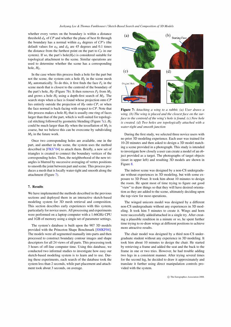
In the case where this process finds a hole for the part butnot the scene, the system cuts a hole HS in the scene meshMS automatically. To do this, it first finds the face FS in thescene mesh that is closest to the centroid of the boundary ofthe part’s hole, HP (Figure 7b). It then removes FS from MSand grows a hole HS using a depth-first search of MS. Thesearch stops when a face is found whose projection onto CPlies entirely outside the projection of HP onto CP, or whenthe face normal is back-facing with respect to CP. Note thatthis process makes a hole HS that is usually one ring of faceslarger than that of the part, which is well-suited for topologi-cal stitching followed by geometric blending (Figure 7c). HScould be much larger than HP when the tessellation of MS iscoarse, but we believe this can be overcome by subdividingMS in the future work.
Once two corresponding holes are available, one in thepart, and another in the scene, the system uses the methoddescribed in [FKS∗04] to attach them. Briefly, a new set oftriangles is created to connect the boundary vertices of thecorresponding holes. Then, the neighborhood of the new tri-angles is blurred by successive averaging of vertex positionsto smooth the joint between part and scene. This process pro-duces a mesh that is locally water-tight and smooth along theattachment (Figure 7).
7. Results
We have implemented the methods described in the previoussections and deployed them in an interactive sketch-basedmodeling system for 3D mesh retrieval and composition.This section describes early experiences with this system,particularly for novice users. All processing and experimentswere performed on a laptop computer with a 1.66GHz CPUand 1GB of memory using a single set of parameter settings.
The system’s database is built upon the 907 3D modelsprovided with the Princeton Shape Benchmark [SMKF04].The models were all segmented manually into parts and thenprocessed to construct boundary contour images and shapedescriptors for all 24 views of all parts. This processing took3 hours of off-line computer time. Using this database, weconducted two informal studies to investigate how easy oursketch-based modeling system is to learn and to use. Dur-ing these experiments, each search of the database took thesystem less than 2 seconds, while part placement and attach-ment took about 3 seconds, on average.
Figure 7: Attaching a wing to a rabbit. (a) User draws awing. (b) The wing is placed and the closest face on the sur-face to the centroid of the wing’s hole is found. (c) New holeis created. (d) Two holes are topologically attached with awater-tight and smooth junction
During the first study, we selected three novice users withno prior 3D modeling experience. Each user was trained for10-20 minutes and then asked to design a 3D model match-ing a scene provided in a photograph. This study is intendedto investigate how closely a user can create a model of an ob-ject provided as a target. The photographs of target objects(inset in upper left) and resulting 3D models are shown inFigure 8.
The indoor scene was designed by a non-CS undergradu-ate without experiences in 3D modeling, but with some ex-posure to 3D Poser. It took him about 10 minutes to designthe room. He spent most of time trying to figure out good”view” to draw things so that they will have desired orienta-tion as they are added to the scene, ultimately deciding uponthe top-view for most operations.
The winged unicorn model was designed by a differentnon-CS undergraduate without any experiences in 3D mod-eling. It took him 5 minutes to create it. Wings and hornwere successfully added/attached in a single try. After creat-ing a plausible rendition in a minute or so, he spent furthertime trying to re-draw wings at different positions to achievemore attractive results.
The chair model was designed by a third non-CS under-graduate student without any experience in 3D modeling. Ittook him about 10 minutes to design the chair. He startedby retrieving a frame and added the seat and the back to theframe in one or two tries. However, he had trouble addingtwo legs in a consistent manner. After trying several timesfor the second leg, he decided to draw it approximately andtranslate it further using direct manipulation controls pro-vided with the system.
c© The Eurographics Association 2008.

Jeehyung Lee & Thomas Funkhouser / Sketch-Based Search and Composition of 3D Models
Figure 8: 3D models created by novice users in 5-10 minutesafter 10-20 minutes of instructions. The target provided tothe user is shown above-and-left of each model.
During informal surveys, we found that all three usersfound the design process “intuitive” and generally were sat-isfied with the search results and part placements providedautomatically by the system. However, they also found thatit is hard to perform certain operations in our system. Forexample, when adding legs to both side of the chair as inFigure 8, it is hard to add them in exactly same sizes and inexactly symmetric manner, as sketches tend to be casual. Ofcourse, further capabilities to enforce symmetric edits couldbe added to the system, but features of this type are beyondthe scope of this paper.
During a second study, we selected two different noviceusers to create a model of their own design using the system.This study was intended to investigate the suitability of thesystem for conceptual design. Figure 9 shows the results,each of which was made in 15-20 minutes.
Figure 9: 3D models designed and created by novice usersin 15-20 minutes. Inset images are colored by part.
In general, these users found the system easy to learn anduseful for creating new models. Even when a user had onlyan abstract idea of what he wanted to add to a scene, he couldalways draw a shape, and pick a part that he found interest-ing from query results. Moreover, as each step of composi-tion requires only a single sketch, and the system supportsinfinite undo’s, the user could try out his ideas with littleburden. This suggests that our approach not only lowers thetechnical threshold to 3D modeling, but also that of artisticcreation as well.
8. Conclusion & Future Work
In this paper, we investigate a new type of modeling sys-tem for creating a new 3D object or scene with a sketchinginterface. The system overcomes limitations of both popularapproaches in easy 3D modeling, sketch based modeling andmodeling by composition. User experiences with our proto-type system suggest that the system is indeed easy to learnand can create interesting and detailed 3D models.
This paper provides only a small, first step towards thegoal of providing advanced modeling to novice users. Whilewe do believe that our system is easier to learn and fasterto use than any other system capable of producing mod-els with the same detail, there still are many limitationsand areas for future improvement. One possible area of fu-ture work is to investigate ways to allow composition ofparts while maintaining global constraints (e.g., symme-tries), as discussed in previous section. Another possibleresearch topic is to investigate sketch-based methods thatsupport not only search and composition, but also deforma-tion. For example, currently in our system, the user cannotfind and use an arm that’s bent if there exist only straightarms in the database. In the future, it seems interestingto combine ideas on sketch-based composition of this pa-per with complementary ideas on sketch-based deformation
c© The Eurographics Association 2008.

Jeehyung Lee & Thomas Funkhouser / Sketch-Based Search and Composition of 3D Models
(e.g., [NSACO05,OSSJ05,YZX∗04,ZNA07]). Investigatingother synergies between sketch-based modeling and sketch-based retrieval seems like a fruitful area for future research.
Acknowledgements
We thank Don Kim for assistance with preparing figuresand the National Science Foundation (CNS-0406415, IIS-0612231, and CCF-0702672) and Google for funding.
References
[AS05] ANDREOU I., SGOUROS N.: Shape-based re-trieval of 3d models in scene synthesis. 3124–3129.
[BCCD04] BOURGUIGNON D., CHAINE R., CANI M.-P., DRETTAKIS G.: Relief: A modeling by drawing tool.In EUROGRAPHICS Workshop on Sketch-Based Inter-faces and Modeling (2004).
[FKS∗04] FUNKHOUSER T., KAZHDAN M., SHILANE
P., MIN P., KIEFER W., TAL A., RUSINKIEWICZ S.,DOBKIN D.: Modeling by example. In Proceedings ofSIGGRAPH 2004 (2004).
[FMK∗03] FUNKHOUSER T., MIN P., KAZHDAN M.,CHEN J., HALDERMAN A., DOBKIN D., JACOBS D.: Asearch engine for 3d models. In ACM Transactions onGraphics (2003), vol. 22, pp. 83–105.
[HR06] HOU S., RAMANI K.: Sketch-based 3d engineer-ing part class browsing and retrieval. In EUROGRAPH-ICS Workshop on Sketch-Based Interfaces and Modeling(2006).
[HR07] HOU S., RAMANI K.: Classifier combination forsketch-based 3d part retrieval. Journal of Computers &Graphics 31 (2007).
[IH03] IGARASHI T., HUGHES J. F.: Smooth meshes forsketch-based freeform modeling. In ACM Symposium onInteractive 3D Graphics (2003), pp. 139–142.
[IMT99] IGARASHI T., MATSUOKA S., TANAKA H.:Teddy: A sketching interface for 3d freeform design. InProceedings of SIGGRAPH 1999 (1999), pp. 409–416.
[JPR05] JIANTAO PU K. L., RAMANI K.: A 2d sketch-based user interface for 3d cad model retrieval. Computer-Aided Design & Applications 2, 6 (2005), 717–725.
[KH05] KARPENKO O., HUGHES J. F.: Inferring 3d free-form shapes from contour drawings. In SIGGRAPH Tech-nical Sketches (2005).
[KH06] KARPENKO O., HUGHES J. F.: Smoothsketch:3d free-form shapes from complex sketches. ACM Trans-actions on Graphics (SIGGRAPH 2006) (2006).
[KJS07] KRAEVOY V., JULIUS D., SHEFFER A.: Shuf-fler: Modeling with interchangeable parts. In Visual Com-puter Journal 2007 (2007).
[KQW06] KU D. C., QIN S. F., , WRIGHT D. K.: Asketching interface for 3d modeling of polyhedrons. In
EUROGRAPHICS Workshop on Sketch-Based Interfacesand Modeling (2006).
[LJW06] LIN J., JIN X., , WANG C.: Sketch based meshfusion. Advances in Computer Graphics 4035 (2006), 90–101.
[Lof00] LOFFLER J.: Content-based retrieval of 3d modelsin distributed web databases by visual shape information.iv 00 (2000), 82.
[NISA07] NEALEN A., IGARASHI T., SORKINE O.,ALEXA M.: Fibermesh: Designing freeform surfaces with3d curves. In Proceedings of SIGGRAPH 2007 (2007).
[NSACO05] NEALEN A., SORKINE O., ALEXA M.,COHEN-OR D.: A sketch-based interface for detail-preserving mesh editing. In Proceedings of SIGGRAPH2005 (2005), pp. 1142–1147.
[ONI06] OWADA S., NIELSEN F., IGARASHI T.: Copy-paste synthesis of 3d geometry with repetitive patterns.Lecture Notes in Computer Science 4073 (2006), 184–193.
[OSSJ05] OLSEN L., SAMAVATI F., SOUSA M., JORGE
J.: Sketch-based mesh augmentation. In Eurograph-ics Workshop on Sketch-Based Interfaces and Modeling(2005).
[SBSC06] SHARF A., BLUMENKRANTS M., SHAMIR
A., COHEN-OR D.: SnapPaste: an interactive techniquefor easy mesh composition. 835–844.
[SCoL∗04] SORKINE O., COHEN-OR D., LIPMAN Y.,ALEXA M., ROESSL C., SEIDEL H. P.: Laplacian sur-face editing. In In Proc. Eurographics/ACM SIGGRAPHsymposium on Geometry processing (2004), pp. 179–188.
[SI07] SHIN H., IAGARASHI T.: Magic canvas: Inter-active design of a 3-d scene prototype from freehandsketches. In Proceedings of Graphics Interface 2007(2007).
[SMKF04] SHILANE P., MIN P., KAZHDAN M.,FUNKHOUSER T.: The Princeton Shape Benchmark. InShape Modeling International (June 2004), pp. 167–178.
[YSv05] YANG C., SHARON D., VAN DE PANNE M.:Sketch-based modeling of parameterized objects. EU-ROGRAPHICS Workshop on Sketch-Based Interfaces andModeling (2005).
[YZX∗04] YU Y., ZHOU K., XU D., SHI X., BAO H.,GUO B., SHUM H.-Y.: Mesh editing with poisson-basedgradient field manipulation. In ACM Transactions onGraphics (2004), vol. 23.
[ZNA07] ZIMMERMANN J., NEALEN A., ALEXA M.:Silsketch: Automated sketch-based editing of surfacemeshes. In EUROGRAPHICS Workshop on Sketch-BasedInterfaces and Modeling (2007).
[ZPF96] ZELENIK R. C., P.HERNDON K., F.HUGHES J.:Sketch: An interface for sketching 3d scenes. In Proceed-ings of SIGGRAPH 1996 (1996).
c© The Eurographics Association 2008.