
Sketch-Based Garment Design with Quad Meshes · Sketch-Based Garment Design with Quad Meshes Zahraa...
7
HAL Id: hal-00813674 https://hal.archives-ouvertes.fr/hal-00813674 Submitted on 30 Sep 2013 HAL is a multi-disciplinary open access archive for the deposit and dissemination of sci- entific research documents, whether they are pub- lished or not. The documents may come from teaching and research institutions in France or abroad, or from public or private research centers. L’archive ouverte pluridisciplinaire HAL, est destinée au dépôt et à la diffusion de documents scientifiques de niveau recherche, publiés ou non, émanant des établissements d’enseignement et de recherche français ou étrangers, des laboratoires publics ou privés. Sketch-Based Garment Design with Quad Meshes Zahraa Yasseen, Ahmad Nasri, Wajih Boukaram, Pascal Volino, Nadia Magnenat-Thalmann To cite this version: Zahraa Yasseen, Ahmad Nasri, Wajih Boukaram, Pascal Volino, Nadia Magnenat-Thalmann. Sketch- Based Garment Design with Quad Meshes. Computer-Aided Design, Elsevier, 2013, pp.Pages 562-567, ISSN 0010-4485. <hal-00813674>
Transcript of Sketch-Based Garment Design with Quad Meshes · Sketch-Based Garment Design with Quad Meshes Zahraa...

HAL Id: hal-00813674https://hal.archives-ouvertes.fr/hal-00813674
Submitted on 30 Sep 2013
HAL is a multi-disciplinary open accessarchive for the deposit and dissemination of sci-entific research documents, whether they are pub-lished or not. The documents may come fromteaching and research institutions in France orabroad, or from public or private research centers.
L’archive ouverte pluridisciplinaire HAL, estdestinée au dépôt et à la diffusion de documentsscientifiques de niveau recherche, publiés ou non,émanant des établissements d’enseignement et derecherche français ou étrangers, des laboratoirespublics ou privés.
Sketch-Based Garment Design with Quad MeshesZahraa Yasseen, Ahmad Nasri, Wajih Boukaram, Pascal Volino, Nadia
Magnenat-Thalmann
To cite this version:Zahraa Yasseen, Ahmad Nasri, Wajih Boukaram, Pascal Volino, Nadia Magnenat-Thalmann. Sketch-Based Garment Design with Quad Meshes. Computer-Aided Design, Elsevier, 2013, pp.Pages 562-567,ISSN 0010-4485. <hal-00813674>

Author manuscript, published in “Computer-Aided Design (2013)”DOI: 10.1016/j.cad.2012.10.041
Sketch-BasedGarment Design withQuadMeshes
Z. Yasseen a A. Nasri a,2 W. Boukaram a P. Volino b N. Magnenat-Thalmann b
aASHA Graphics and Animation Lab, American University of BeirutbMIRALab, University of Geneva
Abstract
Garment creation continues to be the most tedious part of the virtual clothing process. In this paper, we present an easy to usesketch-based cloth modeling approach. Contours can be easily sketched on a mannequin to generate quad meshes to representpieces of cloth already fit and draped. Typically, the clothing process depends highly on the meshing scheme that has to infer itsgeometry from the input boundary. Our quad meshing scheme is based on discrete Coons patches but with arbitrary boundaryinput. We also apply the permanence principle to our topological solution to allow more control over the influence of the inputboundary polyline on the interior output polygonal mesh. This facilitates the creation of folds that are strongest in curvature atthe boundary and which diminish towards the interior. The generated garments can then be easily animated in a simulation systembased on Finite Elements, using a rediscretization of the generated mesh and a reconstructed metric of the cloth surface.
Key words: garment design, sketch–based modeling, quad meshing, extra–ordinary vertices, discrete Coons, permanence patches, physicalsimulation, Finite Elements
1. Introduction
Modeling cloth without having to design pieces of gar-ment and their seaming associations is a major attractionin cloth modeling and animation. In this paper, we presenta sketch-based approach for modeling cloth described bya network of polylines input by the user from different 2Dviews in a virtual 3D environment. We start by setting a3Dmannequin and some auxiliary planes,to sketch the out-lines of the cloth. Out of a network of boundary polylines,we construct high quality quad meshes representing clothpieces. Every piece of the generated cloth is then associatedto an underlying body part or a corresponding sub-mesh.
The contribution of our work lies in the design of quadmeshes from sketched contours of the desired garments. Theliterature presents us with criteria to compare the results ofvarious meshing schemes. The authors in [1] quantified thiscriteria by the distortion of the mesh 3 and limited their
1 This work was supported in part by a grant # LCR 111135-522182from the Lebanese National Council for Scientific Research and a
grant # 111135-526168 from the Francophone agency to AUB incollaboration with MIRALAB at the University of Geneva.2 Corresponding author3 The distortion of a mesh is the sum of distortion on all the verticesof the mesh. The distortion on a vertex is, in turn, the deviation ofits valence from the regular setting (4 for interior, 3 for boundary,and 2 for corner vertices).
quad meshing scheme to instances of the problem wherethe minimum of this distortion is attainable. Their workis mainly concerned with finding a topological solution –the vertices and their connectivity – where the geometry ofthe resulting mesh is an assembly of rectangular DiscreteCoons Patches [7]. In this paper, we extend their work to filla larger variety of n-sided regions by introducing additionaldislocations and allowing an increase in the distortion butwith the least possible amount. Moreover, we generalizedthe permanence principle [7] to quad mesh a region with anarbitrary topological input to allow more control over theweight of the boundary vertices propagated towards theinterior of the mesh.For the purpose of visualization, we implement a fast
Finite-Element simulation system which combines the abil-ity of representing accurately the nonlinear anisotropic be-havior of cloth materials along a particle-system represen-tation allowing the use of efficient numerical integrationmethods along the possibility of handling collisions and ge-ometrical constraints efficiently [20]. Thanks to a dedicatedcollision processing, the cloth respond appropriately to themotion of the body, which can set to various poses or per-form various animations.The remainder of this paper is organized as follows. Sec-
tion 2 gives an overview of related work. The cloth mod-eling application along with its three main phases, namely
1

sketching, meshing, and refitting, are detailed out in section3. We describe the mechanical simulation system in Section4. Section 5 outlines the conclusion and future work.
2. Related Work
The dominating method that is adopted in virtual cloth-ing is the 2D pattern construction and draping of the con-stituting pieces of cloth. However, sketch-based cloth mod-eling has received some attention. Turquin et al. [18] devel-oped a sketch-based interface that would let users construct3D virtual garments on a character model. Their systemcomputes distance-to-the-body for the silhouette lines andpoint-to-body distances for the borderlines. It then propa-gates this distance information in 2D to find desired point-to-body distances, which it uses to determine the garment’s3D position. Folds are incorporated by strokes that markthe presence of either ridges or valleys.Wang et al. [6] modela 3D garment around a 3D human model by 2D sketchesinput. A feature template for creating a customized 3D gar-ment is defined according to the features on a humanmodel.Then the profiles of the 3D garment are specified through2D sketches. The smooth mesh surface interpolating thespecified profiles is constructed by a modified variationalsubdivision scheme.
In a somewhat different context, Han et al. [8] computedthe 3D shape of cloth from a single image. They presentan algorithm that finds the shading primitives on a clothimage and simultaneously recovers their 3D shape by fit-ting to the 3D fold primitives obtained through photomet-ric stereo. Chen et al. [5] reconstruct generic images by us-ing an attributed graph representation for clothes with adictionary of image primitives where each stroke may cor-respond to folds, sewing lines, occluding boundaries, andshape outlines.
Our approach reduces the problem to finding a goodmeshing algorithm to construct cloth pieces from an inputnet of polylines entered by the user as outlined in [22].In general, there are four approaches towards a solution:advancing front, node placement, parametric curves, andthe topological approach. In the advancing front tech-nique [3,21,15,16], a set of fronts are defined consisting ofthe edges at the boundary of the domain. Quads are sys-tematically combined at the front, advancing towards theinterior of the area. The node placement process [17,14,10]is made of two stages the positions of the nodes are com-puted first and their connectivity is decided next. Thethird approach uses subdivision surfaces and differs in thenature of data input. Given an n–sided region bounded byn parametric curves and a user defined vertex G, connectG with the middle parameter point on each side construct-ing an initial quad-based control net [2,19,4,9,11]. Thetopological approach [1,12] aims at generating the quadmesh topology regardless of the geometric conditions atthe boundary. In an afterward phase, the locations of thevertices are determined.
(a) Boundarylines sketched
on the man-nequin.
(b) The gen-erated quad
mesh.
(c) The gar-ments refit to
the underlyingskin.
(d) The gar-ment com-
prised of partscombined us-ing a mirror
operation.
Fig. 1. Cloth generation from boundary lines sketched on a man-nequin.
3. The Sketch-Based Cloth Modeling Approach
The sketch-based cloth modeling approach allows clothdesign in a triple-phase process (see Fig. 1 and Fig. 12).First, the user draws the nets of polylines that represent thedescriptive outline of the cloth (Fig. 1(a)). Then, the closedregions in the net of polylines are filled with quad meshes(Fig. 1(b)). In the last phase cloth-body associations areestablished so that every piece of cloth has a correspondingunderlying body part (Fig. 1(c)). This is done either auto-matically by computing the enclosed submesh or by manu-ally selecting the polygonal faces comprising the submeshof the mannequin when the cloth is loose. We use theseassociations to resolve cloth-body interpenetration as wellas for collision detection and handling at animation time.Simple operations such as mirror and join can be appliedlater on the resulting mesh (Fig. 1(d)).
3.1. Sketching in a 3D Environment
Fig. 2. The outlines of a jacket sketched in the front and back view.
The sketching environment is a multi-view (orthographicand perspective) paneled window. The mannequin –alignedalong the y-axis in a standing position– is the basic elementin the scene. When the user draws in the front view, theinput lines either lie in the xy plane or on the mesh of themodel with a user defined offset (see Fig. 2).It is possible that the system planes (xy, xz, and yz) may
not be enough to include all parts of the input outlines.
2
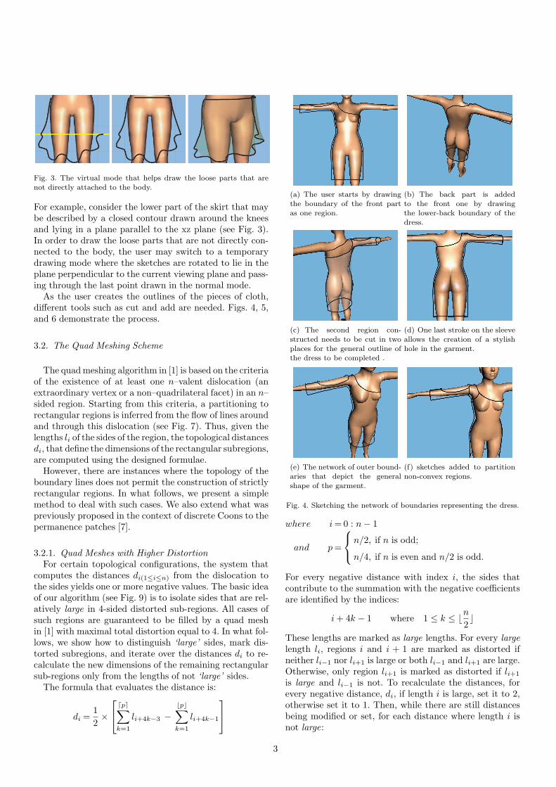
Fig. 3. The virtual mode that helps draw the loose parts that arenot directly attached to the body.
For example, consider the lower part of the skirt that maybe described by a closed contour drawn around the kneesand lying in a plane parallel to the xz plane (see Fig. 3).In order to draw the loose parts that are not directly con-nected to the body, the user may switch to a temporarydrawing mode where the sketches are rotated to lie in theplane perpendicular to the current viewing plane and pass-ing through the last point drawn in the normal mode.
As the user creates the outlines of the pieces of cloth,different tools such as cut and add are needed. Figs. 4, 5,and 6 demonstrate the process.
3.2. The Quad Meshing Scheme
The quadmeshing algorithm in [1] is based on the criteriaof the existence of at least one n–valent dislocation (anextraordinary vertex or a non–quadrilateral facet) in an n–sided region. Starting from this criteria, a partitioning torectangular regions is inferred from the flow of lines aroundand through this dislocation (see Fig. 7). Thus, given thelengths li of the sides of the region, the topological distancesdi, that define the dimensions of the rectangular subregions,are computed using the designed formulae.
However, there are instances where the topology of theboundary lines does not permit the construction of strictlyrectangular regions. In what follows, we present a simplemethod to deal with such cases. We also extend what waspreviously proposed in the context of discrete Coons to thepermanence patches [7].
3.2.1. Quad Meshes with Higher DistortionFor certain topological configurations, the system that
computes the distances di(1≤i≤n) from the dislocation tothe sides yields one or more negative values. The basic ideaof our algorithm (see Fig. 9) is to isolate sides that are rel-atively large in 4-sided distorted sub-regions. All cases ofsuch regions are guaranteed to be filled by a quad meshin [1] with maximal total distortion equal to 4. In what fol-lows, we show how to distinguish ‘large’ sides, mark dis-torted subregions, and iterate over the distances di to re-calculate the new dimensions of the remaining rectangularsub-regions only from the lengths of not ‘large’ sides.
The formula that evaluates the distance is:
di =1
2×
⌈p⌉∑k=1
li+4k−3 −⌊p⌋∑k=1
li+4k−1
(a) The user starts by drawingthe boundary of the front part
as one region.
(b) The back part is addedto the front one by drawing
the lower-back boundary of thedress.
(c) The second region con-structed needs to be cut in twoplaces for the general outline of
the dress to be completed .
(d) One last stroke on the sleeveallows the creation of a stylishhole in the garment.
(e) The network of outer bound-aries that depict the generalshape of the garment.
(f) sketches added to partitionnon-convex regions.
Fig. 4. Sketching the network of boundaries representing the dress.
where i= 0 : n− 1
and p=
n/2, if n is odd;
n/4, if n is even and n/2 is odd.
For every negative distance with index i, the sides thatcontribute to the summation with the negative coefficientsare identified by the indices:
i+ 4k − 1 where 1 ≤ k ≤ ⌊n2⌋
These lengths are marked as large lengths. For every largelength li, regions i and i + 1 are marked as distorted ifneither li−1 nor li+1 is large or both li−1 and li+1 are large.Otherwise, only region li+1 is marked as distorted if li+1
is large and li−1 is not. To recalculate the distances, forevery negative distance, di, if length i is large, set it to 2,otherwise set it to 1. Then, while there are still distancesbeing modified or set, for each distance where length i isnot large:
3

(a) For each closed region, cor-ners are identified by the system
and verified by the user.
(b) Filled with a quad mesh (de-scribed in the next section).
(c) Resolve body-garment inter-penetration.
(d) Mesh beautified using eitheran optimization technique or aparticle system.
Fig. 5. Quad mesh generation.
(a) The front polygonal mesh. (b) The back polygonal mesh.
(c) The Catmull-Clark surface. (d) The Catmull-Clark surface.
Fig. 6. The resultant dress after quadrangulating all closed regions.
a) if di−1 is known,
di+1 =
min(li − di−1, di+1), if di+1 is known;
li − di−1, otherwise.
b) else if di+1 is known,
di−1 =
min(li − di+1, di−1), if di−1 is known;
li − di+1, otherwise.
c) else, di−1 = ⌊ li2 ⌋ and di+1 = ⌈ li
2 ⌉
C0
C1
C2
C3
C4
l0 = 5
l1 = 6
l2 = 3
l3 = 6
l4 = 4
G
d0
d1
d2
d3
d4
E0
E1
E2
E3
E4
d
d
3d
region2
region0
d
region1
region3
3dd3
region4
Fig. 7. The flow of lines (in light red) infer the partitioning torectangular subregions. Regions i and i+1 are associated with side i.
C0
C1
C2 C3
C4
G
(a) l1 is large
C0
C1
C2 C3
C4
G
(b) l1 and l2 are large
C0
C1
C2 C3
C4
G
(c) l0, l1, and l2 arelarge
Fig. 8. Distorted regions (light red) are identified according to largelengths (dark red).
(a) a 3–sided region where only one length is large
(b) a 5–sided region where two adjacent lengths are large
(c) a 5–sided region where three adjacent lengths are large
Fig. 9. Examples of regions filled by quad meshes of non–minimal
distortion. Form left to right: the region defined by boundary poly-lines, distorted subregions (light red) and large lengths (dark red),and the resulting quad mesh.
3.2.2. Permanence PatchesThe generalized approach that is proposed in this paper
introduces slight complications to this boundary–interiorpolyline associations. Using strictly discrete Coons may re-
4

b00
b33
b03
b30
b10
b02
b01
b20
b31
b32
b13
b23
b0,0
b3,3
b0,3
b3,0
b1,0
b0,2
b0,1
b2,0
b3, 1
b3,2
b1,3
b2,3
b1,1
b1,2
b2,2
b2,1
Fig. 10. A configuration where m = n = 3. The gray colored verticesare the unknown interior vertices.
sult in geometrically distorted meshes.According to the permanence principal [7], the relation
between every interior vertex and its immediate neighbors:bi,j = −1
4 (bi−1,j+1 + bi+1,j+1 + bi−1,j−1 + bi+1,j−1)+ 1
4 (bi,j+1 + bi+1,j + bi,j−1 + bi−1,j)A neater way of writing this is using a mask as shown inEq. 1.
bi,j =1
4×
−1 2 −1
2 • 2
−1 2 −1
(1) bi,j =
α β α
β • β
α β α
(2)
The discrete Coons patch has m + 1 × n + 1 vertices; ofthese,m−1 × n−1 are unknown. Eq. 1 gives one equationfor each unknown. Thus we may find the discrete Coonspatch as the solution of a linear system with m− 1 × n− 1equations in as many unknowns.
So far, solving m− 1 × n− 1 equations has given whatwas already available with much less computation in thediscrete Coons. However, the mask in Eq. 1 gives a newinsight towards relating vertices to their neighbors and thusestablishing a global linear system that describes the patch.By preserving relative values, the mask may be written asgiven by Eq. 2. As such, different choices for α and β couldbe used. Note that we always need 4α + 4β = 1 in orderfor 2 to utilize barycentric (or affine) combinations. It isevident that these patches are defined in regular topologywhere the quad mesh is a grid of 4–valent vertices. Thus,for us to use permanence patches in arbitrary topology weneed to generalize the mask to facilitate adding dislocationsand vertices on facets to the system of linear equations.The approach is rather simple. The condition is to satisfythe following equation as we calculate αn for an n–valentvertex:
4α4 + 4β4 = 1
where α4 is the value of the mask for a 4–valent vertex [7].Thus:
αn = α4 ×4
nand βn =
1
n− αn
As for the vertex which belongs to a non–quadrilateralfacet, its diagonal opposite vertex on this facet is the cen-troid of this facet. After defining the mask of every vertex,a linear equation is added to the system. We base this gen-eralization on the general way Farin et al. [7] followed to
Fig. 11. A three sided region filled by a permanence patch withvalues −0.25 (middle) and 0.0 (right) for α.
Fig. 12. Textured cloth designed using a quad mesh generationscheme.
set up the permanence patches. The value of α, and conse-quently β, is a user choice. The feasible range of α valuesis between 0.0 and −0.25 (see Fig 11). Other values mayproduce noisy meshes. The maximal value (0.0) yields ge-ometries that tend to look flat, a feature which diminishesas α decreases towards −0.25.
4. Mechanical Garment Simulation
The first task of mechanical simulation is the construc-tion of a suitable geometric representation of the garmentobject, fitting the requirement of the mechanical simula-tor. Themechanical simulator uses triangle elements, whichis suitable to a precise computation of weft, warp andshear strains and stresses of the cloth material [Volino andMagnenat-Thalmann, 2009]. Thanks to a lumped-mass ap-proximation, the model can be formulated as interactionforces relating particles belonging to the same triangle, de-pending on their relative position. It is therefore essentialfor the simulation mesh to offer suitable geometric prop-erties for efficient mechanical simulation (regularity of themesh, no degenerate (flat) mesh elements...). Hence, ratherthan using the generated patch mesh directly, we performan adaptive rediscretization of the mesh into triangle ele-ments according to size limits and the Delaunay criteria. Tothis mesh is then associated a set of ”material coordinates”representing the metric (rest shape) of the cloth elements.Assuming the initial design roughly represents the tensile
5

Fig. 13. Mechanical garment simulation using various postures andanimation of the character.
cloth deformation at rest, these material coordinates areextracted from the initial shape of the element mapped onits patch. Our mechanical simulation animates the garmentaccording to the following factors:(i) The internal elasticity of the cloth material, repre-
sented by weft, warp and shear strain-stress curves.(ii) Gravity, which pulls the garment downward.(iii) Collision forces, which prevent the penetration of the
garment inside the surface representing the body.Cloth materials are properly represented through nonlinearstrain-stress curves extracted from tensile tests performedon actual materials, or extracted from standard fabric char-acterization procedures [13]. Collisions are detected using aBoundingVolumeHierarchy algorithm, which detects prox-imities between cloth vertices and body polygons. Thesecollisions are integrated into the simulation system as geo-metrical constraints.
5. Conclusion and Future Work
Designing garments from sketched outlines in a 3D envi-ronment alleviates some of the difficulties involved in clothmodeling. Our approach utilizes the enhanced version of aquad meshing algorithm proposed in [1] to construct piecesof cloth from the outlines drawn by the user. For more con-trol over the geometry of the resulting mesh, we propose ageneralized version of permanence patches and introduceweights to the boundary vertices to compute interior vertexpositions. Garment animation also offers interesting per-spectives of the designer, who should be able to assess thedynamic behavior, the fitting and the garment style accord-ing to body poses and motion.
An important future topic to be addressed is the extrac-tion of high-accuracy garment patterns from the obtained3D garment surface. Essentially based on surface unwrap-ping and dart insertion techniques, these should be ableto produce 2D garment patterns which follow basic designrules currently used in the garment industry.
References
[1] Nasri A., Sabin M., and Yasseen Z. Filling n-sided regions
by quad meshes for subdivision surfaces. Computer GraphicsForum, 28:1644–1658(15), September 2009.
[2] A. A. Ball and D. J. T. Storry. Design of an n-sided surface patch
from hermite boundary data. Comput. Aided Geom. Design,6:111–120, 1989.
[3] R. J. Cass, S. E. Benzley, R. J. Meyers, and T. D. Blacker.Generalized 3-d paving: An automated quadrilateral surfacemesh generation algorithm. International Journal for Numerical
Methods in Engineering, 39(9):1475–1489, 1996.[4] P. Charrot and J. A. Gregory. A pentagonal surface patch for
computer aided geometric design. Comput. Aided Geom. Design,
1:87–94, 1984.[5] Hong Chen, Zi Jian Xu, Zi Qiang Liu, and Song Chun Zhu.
Composite templates for cloth modeling and sketching. In CVPR’06: Proceedings of the 2006 IEEE Computer Society Conferenceon Computer Vision and Pattern Recognition, pages 943–950,Washington, DC, USA, 2006. IEEE Computer Society.
[6] Charlie C.L.Wang, Yu Wang, and Matthew M.F.Yuen. Featurebased 3d garment design through 2d sketches. Computer-AidedDesign, 35:659–672, June 2003.
[7] Gerald Farin and Dianne Hansford. Discrete coons patches.Comput. Aided Geom. Des., 16(7):691–700, 1999.
[8] Feng Han and Song-Chun Zhu. Cloth representation by shapefrom shading with shading primitives. In CVPR ’05: Proceedingsof the 2005 IEEE Computer Society Conference on Computer
Vision and Pattern Recognition (CVPR’05) - Volume 1, pages1203–1210, Washington, DC, USA, 2005. IEEE ComputerSociety.
[9] Wei-Chung Hwang and Jung-Hong Chuang. N-sided hole fillingand vertex blending using subdivision surfaces. J. Inf. Sci. Eng.,19(5):857–879, 2003.
[10] B. Joe. Quadrilateral mesh generation in polygonal regions.Computer-Aided Design, 27(3):209–222, 1995.
[11] Adi Levin. Filling n-sided holes by combined subdivisionschemes. In Paul Sablonniere Pierre-Jean Laurent and Larry L.Schumaker, editors, Curve and Surface Design: Saint-Malo,
pages 221–228. Vanderbilt University Press, Nashville, TN, 1999.[12] T. S. Li, C. G. Armstrong, and R. M. McKeag. Quad mesh
generation for k-sided faces and hex mesh generation for trivalent
polyhedra. Finite Elem. Anal. Des., 26(4):279–301, 1997.[13] C. Luible and N. Magnenat-Thalmann. The simulation of cloth
using accurate physical parameters. In CGIM 2008, Insbruck,
Austria, 2008.[14] Satoshi Nagakura, So Noguchi, Kazufumi Kaneda, Hideo
Yamashita, and Vlatko Cingoski. Automatic quadrilateralmesh generation for fem using dynamic bubble system. IEEETRANSACTIONS ON MAGNETICS, 37(5):3522–3525, 2001.
[15] Changhyup Park, Jae-Seung Noh, Il-Sik Jang, and Joe M. Kang.A new automated scheme of quadrilateral mesh generation forrandomly distributed line constraints. Comput. Aided Des.,39(4):258–267, 2007.
[16] S. Schaefer, J. Warren, and D. Zorin. Lofting curve networksusing subdivision surfaces, pages 103–114. ACM Press, New
York, NY, USA, 2004.[17] K. Shimada and J. Liao. Quadrilateral meshing with
directionality control through the packing of square cells, 1998.[18] Emmanuel Turquin, Jamie Wither, Laurence Boissieux, Marie-
Paule Cani, and John F. Hughes. A sketch-based interface
for clothing virtual characters. IEEE Comput. Graph. Appl.,27(1):72–81, 2007.
[19] T. Varady and A. P. Rockwood. Geometric construction for
setback vertex blends. Comput. Aided Design, 29:413–425, 1997.[20] P. Volino, N. Magnenat-Thalmann, and F. Faure. A simple
approach to nonlinear tensile stiffness for accurate clothsimulation. ACM Transactions on Graphics, pages 105–116,August 2009.
[21] DavidWhite and Paul Kinney. Redesign of the paving algorithm:Robustness enhancements through element by element meshing.In Proc. 6 th Int. Meshing Roundtable, pages 323–335.
[22] Zahraa Yasseen, Ahmad Nasri, Pascal Volino, and NadiaMagnenat-Thalmann. Towards sketched-based garment designand animation. Singapore, June 2010. Short paper presented at
Computer Graphics International Conference.
6


![CloTH-VTON: Clothing Three-dimensional reconstructionfor ......reconstruct 3D clothing from images for 3D VTON, leveraging garment meshes from MGN [2]. Our work is most similar to](https://static.fdocuments.us/doc/165x107/60b89d7300939e46ff0a380f/cloth-vton-clothing-three-dimensional-reconstructionfor-reconstruct-3d.jpg)