SKA DISH VERIFICATION ANTENNA DVA-1, DESIGN … · 2015-04-17 · SKA DISH VERIFICATION ANTENNA...
81
SKA DISH VERIFICATION ANTENNA DVA-1, DESIGN & FABRICATION NGVLA Meeting, Caltech, Pasadena CA April 8, 2015 Matt Fleming, presenter, on behalf of many contributors. Experience on the following projects UC Berkeley, --- BIMA, CARMA, ATA, US-SKA-TDP Minex Engineering, ---- ATA fab & SKA-DVA-1 fab 1 DVA-1 Design Report, NGVLA Meeting, Caltech, 2015-04-08, Matt Fleming
Transcript of SKA DISH VERIFICATION ANTENNA DVA-1, DESIGN … · 2015-04-17 · SKA DISH VERIFICATION ANTENNA...

SKA DISH VERIFICATION ANTENNA
DVA-1, DESIGN & FABRICATION
NGVLA Meeting, Caltech, Pasadena CA
April 8, 2015
Matt Fleming, presenter, on behalf of many contributors.
Experience on the following projects
UC Berkeley, --- BIMA, CARMA, ATA, US-SKA-TDP
Minex Engineering, ---- ATA fab & SKA-DVA-1 fab
1 DVA-1 Design Report, NGVLA Meeting, Caltech, 2015-04-08, Matt Fleming

The Object of Today’s Talk
DVA-1 Design Report, NGVLA Meeting, Caltech, 2015-04-08, Matt Fleming 2
SKA Dish Verification Antenna 1, known as DVA-1
15m Aperture
Offset Gregorian
0.5 to 10 GHz
Installed 2014
DRAO Canada

DVA-1 Antenna Design Team
US SKA Consortium, NSF
Technology Development Program
Cornel University, Ithaca
Jim Cordes
Lynn Baker
German Cortes
University of California, Berkeley
Jack Welch
Matt Fleming
Dave DeBoer
Jet Propulsion Lab
Sandy Weinreb
Bill Imbraile
Consulting
Roger Schultz
National Research Council Canada
Hertzberg Institute for Astrophysics
CART Program Composite Applications for Radio Astronomy
Dominion Radio Obs. Penticton CART
Gary Hovey
Gordon Lacey
Bruce Veidt
Tony Willis
Richard Hellyer
Hertzberg Inst, Victoria
Joeleff Fitzsimmons
Peter Byrnes
Kei Szeto
3 DVA-1 Design Report, NGVLA Meeting, Caltech, 2015-04-08, Matt Fleming
SKA Office, SPDO
Peter Dewdney
Neil Roddis CART
Program

DVA-1 Fabrication & Funding
Mount Drives & Steel Structures
Minex Engineering Corp.
Wilcox Machine
Harrison Industrial
Glen Crete Fabrication
Majority Fabrication Funding Through NRC
Reflector Surfaces & Support Structures
Dominion Radio Obs. CART Team
Foundation & Site Infrastructure
Penticton Contractors
Composite Tubes & Fittings
Profile Composites
TDP remaining funds
NSF
National Research Council Canada
Hertzberg Institute for Astrophysics
4 DVA-1 Design Report, NGVLA Meeting, Caltech, 2015-04-08, Matt Fleming
SKA SPDO
funds

Outline for this Presentation
Antenna design opportunities with a large array.
Discussion of SKA Dish specs & design drivers.
Optics design. ( feed dependent )
Structural design. ( basic approach )
Reflector design & fabrication. ( new technology from NRC )
Mount design & fabrication. ( low maintenance machinery )
Installation.
Testing.
Comments for future antennas.
DVA-1 Design Report, NGVLA Meeting, Caltech, 2015-04-08, Matt Fleming 5

Design Opportunities with High
Volume Antenna Production.
DVA-1 Design Report, NGVLA Meeting, Caltech, 2015-04-08, Matt Fleming 6
Engineering costs can be amortized over many units.
Complex tooling can be easily justified.
Custom designs for higher reliability are well justified.
Designs with parts that fit shipping containers allows more sources.
Factory assembly and delivery of pre-tested systems is justified.
On site fabrication can use more complex processes.

Dish Specifications &
Design Drivers.
DVA-1 Design Report, NGVLA Meeting, Caltech, 2015-04-08, Matt Fleming 7
Strawman Design
Low Cost and High Performance
Searching for the right compromise.
A discussion of what the SKA wrestled with.

Science Requirements and
Project Cost Tradeoffs
Truth 1: A smaller number of large antennas is better.
Truth 2: A lager number of small antennas is better.
This comes from different interpretations of the following costs:
DVA-1 Design Report, NGVLA Meeting, Caltech, 2015-04-08, Matt Fleming 8
Array Number & Size of Antennas ( Less is More ? )
This discussion is critical during early array design.
Two truths always seem to compete
SKA worked hard on this costing function.
Antennas, Feeds, Baselines, Infrastructure, Maintenance.

Array Design Tradeoffs
1. For an array in survey observation: Truth 2, small dishes.
speed & sensitivity is a function of ND ( where N = number, D = diameter )
2. For an array in point source observation: Truth 1, lager dishes.
speed & sensitivity is a function of ND2
3. Larger antennas require better surface accuracy & pointing, but make
. success more difficult, therefore Truth 2, small dishes.
4. Cost of Feeds, constant but usually high, truth 1, large dishes. ( spend money on research , development & engineering )
5. Cost of Infrastructure, therefore: Truth 1, large dishes.
6. Cost from number of baselines: Truth 1, large dishes.( computing & Moore’s Law )
7. Cost of Maintenance, Truth 1, larger dishes, but really “proven prototypes of
good design is the dominant factor”.
DVA-1 Design Report, NGVLA Meeting, Caltech, 2015-04-08, Matt Fleming 9
Jack Welch
Peter Dewdney

Antenna Design Tradeoffs
What feed systems will be used.
Symmetric vs offset ( lowest frequency )
Offset high vs offset low. ( maybe feed spillover dependant )
Shaped reflectors vs true conic sections.
Paneled reflector vs Single Skin.
Composite vs metal surfaces
Stow position & survival position.
Close spacing short baseline requirements.
Spillover.
DVA-1 Design Report, NGVLA Meeting, Caltech, 2015-04-08, Matt Fleming 10

SKA Antenna Design Drivers
1 Low cost antenna at high volume. ( very system driven )
( low cost materials, low mass design, low fab labor )
2 Low cost operation for a 30 year life.
( very few maintenance visits 60 month interval )( get it right or pay )
3 Allow operational modes to match environment. ( specifications for operation in several environments, high freq on a calm night )
3 Frequency range of 0.5 to 10 GHz. ( 4.0m Gregorian secondary ) ( favors offset )
4 Large & flexible feed area. WBSPF & PAF ( several wide band single pixel feeds & possibly a phased array feed ) ( favors offset )
5 Excellent Ae / Tsys. ( accurate surfaces, controlled spillover, low diffraction ) ( favors offset )
6 Exceptional dynamic range. ( not just accuracy, but very “stable” surfaces, very “consistent” pointing, )
11 DVA-1 Design Report, NGVLA Meeting, Caltech, 2015-04-08, Matt Fleming

Strawman Spec Compare
DVA-1 NGVLA
Dia 15 18 m 1.20
Area 177 254 sq-m 1.44
Frequency Max 10 100 GHz
Surface rms 30 16 N
1.00 0.188 mm W / N
Pointing rms 50 10 N
10.1 4.2 arc-sec B / N
DVA-1 Design Report, NGVLA Meeting, Caltech, 2015-04-08, Matt Fleming 12
Precision pointing at 10 arcsec means
edge movement of 0.74mm ( 0.029”) across 15m.

•A large number of low cost antennas with a single wide band feed.
•Hydroformed aluminum thin primary supported at the rim with flex center.
•Wind & gravity moment loads are reduced with Az & El near the shell center.
•A compact close nested turnhead contains all the precision machining.
•Stow at low elevation and windsock as needed and allow drives to yield.
Building on the ATA experience.
13 DVA-1 Design Report, NGVLA Meeting, Caltech, 2015-04-08, Matt Fleming
Offset low therefore
mount is rather tall.
Primary 6.1 x 7.0m
Secondary 2.4m
Antenna
Cost: $80,000
Weight: 4,350 lbs
18.39 $/lb
2737 $/sq-m
Feed 5D 2015
0.9 to 14 GHz
Cost: $30,000
Weight: 70 lbs
Feed 4C 2009
0.5 to 10 GHz
Cost:
Weight:

•TDP, for reflectors 6 to 12m, hydroforming was projected to be problematic.
•CART, for reflectors at 10m and up composite was looking promising if thiin.
•Composite technology developing in Canada is a perfect solution.
•Work began to apply composite technology to a thin shell antenna.
•Some of the same manufacturing issues are present, but better in composite.
Collaboration US-TDP & NRC-CART
14 DVA-1 Design Report, NGVLA Meeting, Caltech, 2015-04-08, Matt Fleming
DRAO = Dominion Radio Astronomical Observatory
CART = Composite Application Radio Telescope
Prototype 10m complete.
Symmetric with Core, Beams & Hub
Also South Africa

Antenna Several Positions
15 DVA-1 Design Report, NGVLA Meeting, Caltech, 2015-04-08, Matt Fleming
Zenith position Stow Position Low Position

Why This Optics Choice
16 DVA-1 Design Report, NGVLA Meeting, Caltech, 2015-04-08, Matt Fleming

Optics Design Ray trace for shaped optics
DVA-1 Design Report, NGVLA Meeting, Caltech, 2015-04-08, Matt Fleming 17
Unblocked aperture
15.0 x 18.3m Primary
4.0m Secondary
55° Opening 1/2 angle
177 aperture 214 area 22%
Extensive work by Lynn Baker,
German Cortes & Bill Imbriale

Optics Design Features of the design
DVA-1 Design Report, NGVLA Meeting, Caltech, 2015-04-08, Matt Fleming 18
• Clear optical path, no blockage or scattering.
• Shaped optics, leads to very low spillover. (~ -50db wide angle)
• Very low spillover yields very low antenna noise temp. (<6 K ground)
• Very low spillover results in high rejection of RFI and strong sources.
• Shaped optics yield high efficiencies, total result is a high Aeff / Tsys.
• Ample space and access to mount multiple feeds on an indexer.
• PAF works effectively at either secondary or primary focal area
• Feed arm high chosen for structural cost reasons.
• Feed arm low may produce slightly lower spillover for some WBSPFs.
• Feed maintenance access via a standard bucket truck.
• Primary area is 22% over symmetric but antenna cost is 13% more.
• Primary surface accuracy will need to be <1mm rms, 1/30 λ.
More features will be listed in the structural design section.

Optics Design Beam Pattern, 1.4 GHz, Assumed Perfect Feed
DVA-1 Design Report, NGVLA Meeting, Caltech, 2015-04-08, Matt Fleming 19

Optics Design DVA-1 Performance 0.35 to 2.8 GHz
DVA-1 Design Report, NGVLA Meeting, Caltech, 2015-04-08, Matt Fleming 20
Baker 2012-06-29 CDR

Optics Design Low System Noise, Now & Future
DVA-1 Design Report, NGVLA Meeting, Caltech, 2015-04-08, Matt Fleming 21
Lowering Tsys is the most cost effective way to increase sensitivity
Present LNA’s need cryogenics to minimize noise contribution, expensive.
Ongoing trend is ever lower noise & future cryogenics should be lower cost.
Reduce antenna noise contribution to absolute minimum now.
Deep edge tapers improve antenna noise but usually lower efficiency.
Shaping restores the efficiency and optimizes Aeff / Tsys.

Structural Design Antenna Features to Appreciate
DVA-1 Design Report, NGVLA Meeting, Caltech, 2015-04-08, Matt Fleming 22
Reflector surfaces are structural members.
Rim supported surfaces are stable.
Unmatched CTE can be accommodated.
Offset low allows short Mount.
Circular closed deep truss support.
Primary support steel is majority CW.
Reflector set CM location is good.
Reflector Set & Mount interface is simple.
El backlash control via gravity.
Az backlash control via dual drive.
Stow position has low drive loads.
Mount exterior surfaces are load bearing.
Mount interior open for mechanicals.
Total antenna weight 47,000 lbs

Structural Design Antenna Component Masses
23 DVA-1 Design Report, NGVLA Meeting, Caltech, 2015-04-08, Matt Fleming
Rough Estimates on Weight
Total Secondary Assy
Total Primary Assy no CW
Total Turnhead Assy *
Total on El Bearings with CW
Total on Az bearing
Total on Pedestal
Total on Foundation
* no El Actuator
kg
1,711
7,538
5,202
11,955
15,697
17,946
21,434
lbs
3,772
16,618
11,468
26,355
34,606
39,563
47,252

Principle Design Advantages of Molded Single Piece Composite Reflector:
•High thermal stability, very low
CTE
•High part-to-part repeatability
•No assembly labour
•Very durable, zero corrosion
•Very high strength
•No panel gaps = higher
efficiency, lower noise
temperature
24 DVA-1 Design Report, NGVLA Meeting, Caltech, 2015-04-08, Matt Fleming

Shell & Rim Pieces
DVA-1 Design Report, NGVLA Meeting, Caltech, 2015-04-08, Matt Fleming 25
Function of composite backing pieces: to stiffen the rim of the dish and to spread the
load from the outer backing support structure.
Gordon Lacy
CDR
5.3 mm thick Primary
3.0 mm thick Secondary
CTE 3.1 x 10⁻⁶ in/in/F

Backside Center Frame
DVA-1 Design Report, NGVLA Meeting, Caltech, 2015-04-08, Matt Fleming 26
Pentagonal Frame. Built up
from round tubes and end
fittings. A weldment here is
not feasible because of the
large size which precludes
pre-assembly
Triangular Square-Tube
Weldment. Small
enough to ship so it is
welded
Lighter Walled Outer
Tubes
Heavy-Walled Steel Inner
Tubes for Maximum
Stiffness
•The tubular backing structure provides a very stiff foundation for the reflector surface
•Differential thermal expansion issues between dish surface and backing structure are also minimized

Feed Platform & Secondary Support
DVA-1 Design Report, NGVLA Meeting, Caltech, 2015-04-08, Matt Fleming 27
Fabricated Steel Feed
Indexer Support
CFRP Feed Support
Tubes
Large Diameter CFRP
‘Forward’ Feedlegs
Vacuum Infused 4m
Diameter CFRP
Secondary Mirror
•The feedleg and secondary support benefited greatly from
topological optimization studies
•Topological studies forced a rethink of earlier concepts and led
ultimately to the simple and stiff design shown above
Feed Indexer
with 3 feeds
Secondary Support
Tubes 0.9m PAF

28
• Embedded reflective layer technology developed
• A circular cavity test method settled on after initial work with free space testing
• Testing currently includes 3 frequencies, 8.4GHz, 14.4GHz and 18.2GHz
• 100’s of different combinations of materials tested since 2006
• Development continues at higher frequencies
Reflector Design Reflectivity Testing

29
• Materials testing ongoing since 2006
Resin/fibre Strength, stiffness, Poisson
Coefficient of Thermal Expansion (CTE) of resins
and composite panels
Resin shrinkage, resin softening point (Tg, HDT)
In-house testing
Testing used to help determine most suitable
composite materials
Reflector Design Materials Testing

30
The performance of a composite structure is highly dependent on the choice of constituent materials, the fabrication methodology, and the structural design.
• Resin choice: Vinylester Reason: low cost, sufficient strength,
good chemical stability, and well suited to Vacuum Infusion Process.
• Fibre choice: Carbon fibre Reason: highest thermal stability,
highest thermal conductivity, highest stiffness.
• Fabric choice: Triaxial Braid Reason: highest dimensional stability
available, highly orthotropic, very high damage tolerance
Reflector Design Material Choices

31
Additional Material Requirements:
• Creep: A design consideration, alleviate through proper design.
• Fatigue: A design consideration, but not much of a concern in our low
stress, low cyclic loading environment
• UV stability: Block UV with good long life paint
• Water absorption: Low humidity desert environment equals low
absorption, design for slight strength loss.
• Hail damage: Composite panel is more resistant to hail than comparable
aluminum panel.
Reflector Design Materials Development, Other

Feeds and Feed Indexer Concepts
DVA-1 Design Report, NGVLA Meeting, Caltech, 2015-04-08, Matt Fleming 32

Secondary & Feed Platform
DVA-1 Design Report, NGVLA Meeting, Caltech, 2015-04-08, Matt Fleming 33
Secondary reflector 150 Kg FRP composite
Secondary support 40 Kg FRP tubes 75mm dia. Various thicknesses
PAF & positioner 350 Kg Steel
SPFs & indexer 380 Kg Steel & alum
Feed platform 200 Kg Steel
Platform support spars 170 Kg FRP tubes
Total forward of primary: 1290 Kg Not optimized

34
Vacuum Infusion Process (VIP)
chosen because:
fabrication of very large
structure possible
autoclave, fibre placement
machine (necessary for
‘prepreg process’) not
required
part quality and properties very
close to prepreg
Reflector Fabrication

15m Mold Inside Building
DVA-1 Design Report, NGVLA Meeting, Caltech, 2015-04-08, Matt Fleming 35
Finished part:
15.0 m ( 49.2 ft ) wide
18.3 m ( 60.0 ft ) long
5.3 mm ( 0.209 in ) thick
2730 kg ( 6019 lbs ) painted

4m Secondary Mold &
Materials
DVA-1 Design Report, NGVLA Meeting, Caltech, 2015-04-08, Matt Fleming 36
Finished part:
4.0 m ( 13.1 ft ) wide
3.0 mm ( 0.118 in ) thick
108 kg ( 238 lbs ) painted

Tower and Turning Head
Key Features:
• Feed up design allows short, stiff,
and less expensive steel tower
• 60 month maintenance interval.
• Tilt meters installed for improved
pointing performance
• Internal azimuth gear with oil bath
allows remote detection of oil
contamination
• Enclosed rod and cylinder type
linear elevation drive also with oil
lubrication

Major Mount Components
and Deliverables
DVA-1 Design Report, NGVLA Meeting, Caltech, 2015-04-08, Matt Fleming 38
Turnhead Assy
sophistication
contained here
Part of Reflector-set

Large Structural Pieces
Cone as
Container Cargo
Machined Flange
39 DVA-1 Design Report, NGVLA Meeting, Caltech, 2015-04-08, Matt Fleming
•Azimuth Bearings require a very flat mounting surfaces.
•Support section has important features, drum top, tube length greater than
diameter. Errors at lower flange transfers 13% through to upper flange.
•Turnhead attempts to move loads to outer skin and onto bearing.
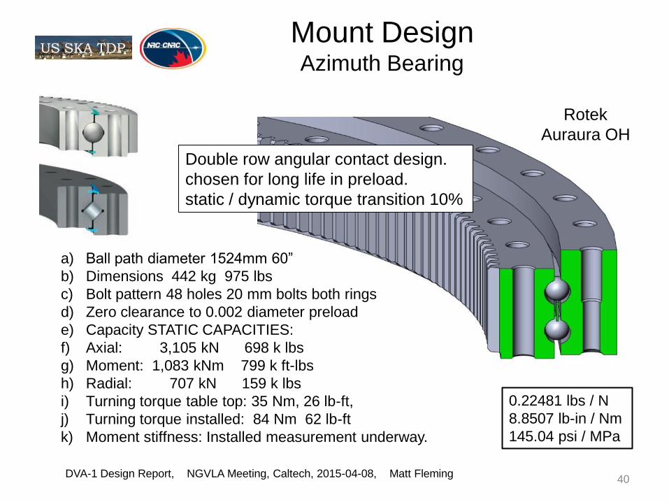
Mount Design Azimuth Bearing
DVA-1 Design Report, NGVLA Meeting, Caltech, 2015-04-08, Matt Fleming 40
a) Ball path diameter 1524mm 60”
b) Dimensions 442 kg 975 lbs
c) Bolt pattern 48 holes 20 mm bolts both rings
d) Zero clearance to 0.002 diameter preload
e) Capacity STATIC CAPACITIES:
f) Axial: 3,105 kN 698 k lbs
g) Moment: 1,083 kNm 799 k ft-lbs
h) Radial: 707 kN 159 k lbs
i) Turning torque table top: 35 Nm, 26 lb-ft,
j) Turning torque installed: 84 Nm 62 lb-ft
k) Moment stiffness: Installed measurement underway.
0.22481 lbs / N
8.8507 lb-in / Nm
145.04 psi / MPa
Double row angular contact design.
chosen for long life in preload.
static / dynamic torque transition 10%
Rotek
Auraura OH

Metrology System
DVA-1 Design Report, NGVLA Meeting, Caltech, 2015-04-08, Matt Fleming 41

Metrology System
DVA-1 Design Report, NGVLA Meeting, Caltech, 2015-04-08, Matt Fleming 42

Az Drive Exploded View
DVA-1 Design Report, NGVLA Meeting, Caltech, 2015-04-08, Matt Fleming 43
Slew speed 3.0 deg/sec
Reducers 159 kg ( 350 lbs )
Pinion ratio 12.889
Reducer ratio 377
Total ratio 4860 az axis to motor
Gears are M6 module about 4.233 DP
Bull 232, Idlers 26, pinion 18 teeth.
Oil bath lubrication.
Bearings and gering
in oil bath.
Az drive
modules

Az Bearing & Drive Parts
DVA-1 Design Report, NGVLA Meeting, Caltech, 2015-04-08, Matt Fleming 44
Oil bath lubricated
Pumped oil lubrication
Unit weight 350 lbs

Removal of Reducer
Module
DVA-1 Design Report, NGVLA Meeting, Caltech, 2015-04-08, Matt Fleming 45
Small light weight
removal crane
snap on installation

Elevation Bearing Design
DVA-1 Design Report, NGVLA Meeting, Caltech, 2015-04-08, Matt Fleming 46
Features
•Designed for minimum cantilever
•Bearing is fairly common and available.
•Allows for large hole to interior.
•Turnhead housing bored only.
•Bearing outside ring pressed in.
•Bearing inside ring taper expanded.
•Exposed shaft and cap parts are plated.
•Seals are high quality press in type.
Replacement
• Bearing and shaft are replaceable in position, with special tools.
• Housing removable via 4 bolts and hydraulic release on bearing bore.
• Shaft removable via remove internal nut and use hydraulic pulling tool,

Elevation Drive Balance
DVA-1 Design Report, NGVLA Meeting, Caltech, 2015-04-08, Matt Fleming 47
The elevation axis has been
positioned so the center of
mass is at a reasonable radius
of about 0.583 m.
The counter-weight CW has
been tuned to locate the CM
for best anti-backlash effect.
The actuator has about 48,000
N or 10,790 lbs.
2,122 kN nut.
1,736 kN col lim 3.62 SF
General notes:
Target slew is 0.75 to 1.00 deg/sec slew
using a 2400 rpm motor gives
ratios of 14,000:1 to 19,000:1

Actuator Key Components
DVA-1 Design Report, NGVLA Meeting, Caltech, 2015-04-08, Matt Fleming 48
Also needs: oil pump, oil level sensor, spring brake, effective seals.
Limits may be part of the actuator or at internal elevation encoder

El Drive Fabrication
DVA-1 Design Report, NGVLA Meeting, Caltech, 2015-04-08, Matt Fleming 49
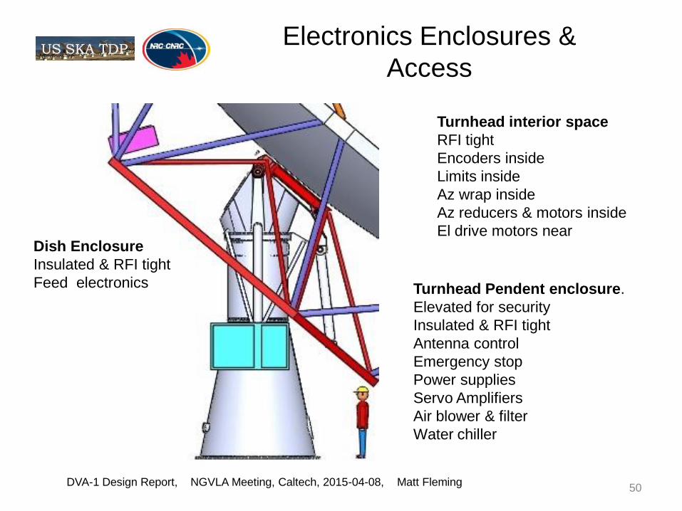
Electronics Enclosures &
Access
DVA-1 Design Report, NGVLA Meeting, Caltech, 2015-04-08, Matt Fleming 50
Turnhead Pendent enclosure.
Elevated for security
Insulated & RFI tight
Antenna control
Emergency stop
Power supplies
Servo Amplifiers
Air blower & filter
Water chiller
Dish Enclosure
Insulated & RFI tight
Feed electronics
Turnhead interior space
RFI tight
Encoders inside
Limits inside
Az wrap inside
Az reducers & motors inside
El drive motors near

Finished Mount Parts Fabricated in Los Angeles Area
DVA-1 Design Report, NGVLA Meeting, Caltech, 2015-04-08, Matt Fleming 51
126” dia max
1/2” plate
on sides
60” dia
1/2” plate
on sides

Pedestal Cone on Mill
DVA-1 Design Report, NGVLA Meeting, Caltech, 2015-04-08, Matt Fleming 52

Turnhead Support on Lathe
DVA-1 Design Report, NGVLA Meeting, Caltech, 2015-04-08, Matt Fleming 53

Turnhead Housing on Mill
DVA-1 Design Report, NGVLA Meeting, Caltech, 2015-04-08, Matt Fleming 54
Conventional machines
and conventional tolerances
typical +/- 0.002” & +/- 0.003”

Turnhead Housing on Mill
DVA-1 Design Report, NGVLA Meeting, Caltech, 2015-04-08, Matt Fleming 55

Turnhead Proof Assy at Minex Antioch
DVA-1 Design Report, NGVLA Meeting, Caltech, 2015-04-08, Matt Fleming 56

Mount Ready for Transport
DVA-1 Design Report, NGVLA Meeting, Caltech, 2015-04-08, Matt Fleming 57

Triangle Frame Dish
Attachment
DVA-1 Design Report, NGVLA Meeting, Caltech, 2015-04-08, Matt Fleming 58

Installing Backup Structure
• Quick assembly, 6 hours, 5 to 6 workers
• Design allows lifespan (post-assembly)
adjustment of primary reflector surface at rim

May 7 2014: Final Lift.
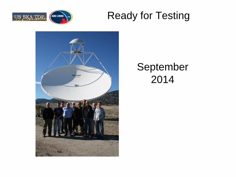
Ready for Testing
September
2014

Secondary Reflector Scan
DVA-1 Secondary surface
0.20 mm RMS part
no aperture weighting
0.16 mm RMS part
with aperture weighting,
Much better results are
possible as shown with
subsequent similar parts.

Improved Results Expected Based on GDSatcom Secondary Reflector
• NRC has now built two sub
reflectors for the GDSatcom
Meerkat project.
• 0.058 mm RMS mold surf
• 0.090 mm RMS part surf
• Similar results for DVA-2
would be expected.
GDSatcom Secondary
•Part2 RMS 0.101mm
•Part1 RMS 0.098mm
•Mold RMS 0.063mm
•Part/mold 1.6

Primary Surface Scan, Rim Horizontal (Bird Bath).
• Most of surface is
within ±1.0mm (green)
• Most red areas are
repaired areas, after
helicopter transport
damage.
• Almost all other
features are in the mold
surface (horizontal
banding, grid feature in
upper right quadrant).
• 0.89 mm RMS
• 0.70 mm RMS
aperture weighting
DVA-1 Design Report,
NGVLA Meeting, Caltech,
2015-04-08, Matt Fleming 64 of 25

Primary Surface Laser Tracker vs Holography
DVA-1 Design Report,
NGVLA Meeting, Caltech,
2015-04-08, Matt Fleming 65 of 25
Registration
Panel
Laser
Tracker
Mount
Repair
Features
Submm
Mold
features
Demonstrates holography is representing surface very well.

Reflector Temperature
Stability
Primary Reflector
Coupon Testing
5.62 μm/moC
DRAO test August 6th
5.42 ± 1.08 μm/moC
Secondary Reflector (estimated)
3.18 μm/moC < CTEsecondary < 5.62 μm/moC
Aluminium > 4 times higher 23.6 μm/moC
DVA-1 Design Report,
NGVLA Meeting, Caltech,
2015-04-08, Matt Fleming 66 of 25

Primary Surface Stability (no correlations, wind or temperature)
DVA-1 Design Report,
NGVLA Meeting, Caltech,
2015-04-08, Matt Fleming 67 of 25
0
0.02
0.04
0.06
0.08
0.1
0.12
0.14
0.16
0.18
0.2
-6.0
-4.0
-2.0
0.0
2.0
4.0
6.0
8.0
10.0
12.0
14.0
0.0 5.0 10.0 15.0 20.0 25.0 30.0
RM
S D
iffe
ren
ce
in
m
m
Te
mp
in
Deg
ree
s C
or
win
d i
n m
ete
rs
pe
r s
ec
on
d, o
r P
k-P
k
dif
fere
nc
e in
mm
Elapsed Time in Hours
Temperature & Wind During Eighteen 1.5 Hour Holography Runs
Run Start: 1 Nov 2014 19:18:09 (PDT) Run End: 2 Nov 2014 23:22:47 (PDT)
Temp (°C)
Wind (mps)
Gust (mps)
Pk-Pk diff (mm)
RMS Difference
Precision Observing < 7mps
Standard Observing
Sunrise 2 Nov 14 @7:49 PDT ; Temp = -3C; ET = 11Hrs
ΔTemp/Δt = 5 °C/Hr

Primary Surface Stability Deviations from Average
18 Holography Maps (28 Hrs)
Average Surf Deviations
RMS 0.85mm
DVA-1 Design Report,
NGVLA Meeting, Caltech,
2015-04-08, Matt Fleming 68 of 25
Deviations from Average
RMS 0.08mm
0.0
0.5

Noise Temperature Testing the MeerKat Receiver
DVA-1 Design Report,
NGVLA Meeting, Caltech,
2015-04-08, Matt Fleming 69 of 25

Noise Temperature EMSS L-Band for MeerKat Receiver
DVA-1 Design Report,
NGVLA Meeting, Caltech,
2015-04-08, Matt Fleming 70 of 25

Azimuth Pattern at 1544.5 MHz (GOES West Satellite)
DVA-1 Design Report,
NGVLA Meeting, Caltech,
2015-04-08, Matt Fleming 71 of 25
Measured matches
predicted very well
to the 3rd side lobe.

Elevation Pattern at 1544.5 MHz (GOES West Satellite)
DVA-1 Design Report,
NGVLA Meeting, Caltech,
2015-04-08, Matt Fleming 72 of 25
Measured matches
predicted very well
to the 3rd side lobe.

Preliminary Tipping Curves
Results
DVA-1 Design Report,
NGVLA Meeting, Caltech,
2015-04-08, Matt Fleming 73 of 25
87 18.5
Results Preliminary and likely low by
as much as 1.5K
58.5
Tsys K
elv
in

Antenna Aeff/Tsys with MeerKat and New (LB) Horn
DVA-1 Design Report,
NGVLA Meeting, Caltech,
2015-04-08, Matt Fleming 74 of 25

Issues and Technical Risks
Key retired technical (technology) risks
Composite reflectors meet requirements for
− Reflectivity
− Mechanical and thermal properties
− Surface accuracy
Outstanding risks now very low.
− Majority have been mitigated by simulation/measurement
− Those remaining will be retired by RF testing
DVA-1 Design Report,
NGVLA Meeting, Caltech,
2015-04-08, Matt Fleming 75 of 25

DVA-1 Costs
Item Materials Labour Sub-contract Totals
Reflectors, feed platform and support structures Composite Dish Surface, Secondary, Central
Reinforcement $111,000 $63,400 Composite Backing Pieces, fabrication portion, not
including molds $23,250
Dish Rim Connector, labour (material in line 3) $14,000
Ball studs $6,132
PDSS $84,874
Feed Platform $6,700
Secondary Support Structure $85,000
Sub Totals $111,000 $77,400 $205,956 $394,356
Pedestal Components
Tower, contract with Minex Engineering $300,000
Tower, misc extra parts, package 1 $19,920
Tower, misc extra parts, package 2 $90,600
Tower, additional items $14,836
Drive system (motors, control system and encoders) $43,000
Painting $5,000
Sub Totals $473,356 $473,356
Grand Total $867,712
297 lbs / sq-m
121 kg / sq-m
4,520 $/sq-m

Comments for Future Antennas
A single piece composite reflector may achieve the
cost objective if the antenna diameter can be kept
smaller.
If a single piece reflector will not achieve the
specification, consider rectangular panels
supported on a space frame type of structure.
There is no reason to use pie segments in high
volume production.
If the dish diameter becomes large and the pointing
spec demanding, consider wheel and track with
new metrology applied.
Accurate wind tunnel data for an offset design is
needed.
DVA-1 Design Report, NGVLA Meeting, Caltech, 2015-04-08, Matt Fleming 77

78
Gary Hovey, Project Manager
250.497.2363
Matt Fleming, presenter [email protected] 925-757-6785 Gordon Lacy, Project Engineer [email protected] 250.497.2340
78 of 25
Questions?

Extra Slide Discussion Topics
DVA-1 Design Report, NGVLA Meeting, Caltech, 2015-04-08, Matt Fleming 79

Extra Slide Mold & Part Accuracy
DVA-1 Design Report, NGVLA Meeting, Caltech, 2015-04-08, Matt Fleming 80
Summary of measured data for molds and reflectors:
DVA1 prmry mold: 0.47 uniform weight, 0.39 amplitude weight
DVA1 prmry part: 0.89 uniform weight, 0.77 amplitude weight
DVA1 prmry part: 0.69 uniform weight, clipped at 1.5 mm., 9% of points
dropped: (drops data from the worst damage spots only)
DVA1 scndry mold: 0.12 uniform weight, 0.11 amplitude weight
DVA1 scndry part: 0.20 uniform weight, 0.16 amplitude weight
DVA2 prmry mold: 0.20 uniform weight, with new high tol mold.

Full Antenna Assembly
DVA-1 Design Report, NGVLA Meeting, Caltech, 2015-04-08, Matt Fleming 81