SKA and SKA demonstrators - School of Physics · The Square Kilometre Array (SKA) The next...
44
Telescopes of the future: SKA and SKA demonstrators Elaine Sadler, University of Sydney • Aperture synthesis techniques have now been in use for over 40 years (1974 Nobel prize to Martin Ryle) - what next? • Why are we planning new telescopes? • What will they look like? • What are the challenges?
Transcript of SKA and SKA demonstrators - School of Physics · The Square Kilometre Array (SKA) The next...

Telescopes of the future: SKA and SKA demonstratorsElaine Sadler, University of Sydney
• Aperture synthesis techniques have now been in use
for over 40 years (1974 Nobel prize to Martin Ryle) - what next?
• Why are we planning new telescopes?
• What will they look like?
• What are the challenges?
Why new radio telescopes?
• “Because we can” (new technologies)
• “Because we can‟t NOT” (or we‟ll fall behind and become
irrelevant) (Moore‟s law, R. Ekers)
• To keep up with next-generation optical/IR telescopes
• To make new discoveries (new parameter space)
• To explore the distant universe (orders of magnitude increase in
sensitivity)
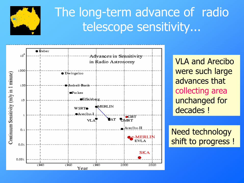
The long-term advance of radio telescope sensitivity...
VLA and Arecibowere such largeadvances that collecting areaunchanged for decades !
Need technologyshift to progress !

Probing the distant universe
HST VLA SKA
In past few years, optical telescopes have begun to probe the `normal‟ galaxy population to z~3
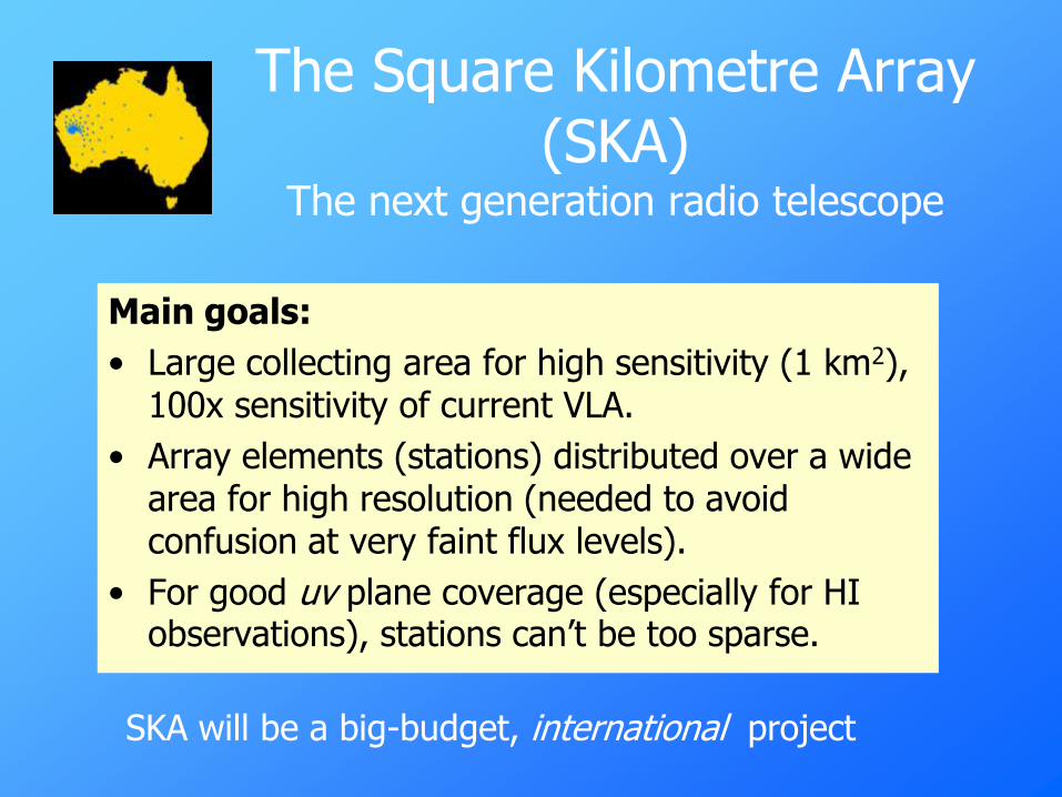
The Square Kilometre Array (SKA)
The next generation radio telescope
Main goals:
• Large collecting area for high sensitivity (1 km2), 100x sensitivity of current VLA.
• Array elements (stations) distributed over a wide area for high resolution (needed to avoid confusion at very faint flux levels).
• For good uv plane coverage (especially for HI observations), stations can‟t be too sparse.
SKA will be a big-budget, international project

SKA collecting area up to 100x VLA

Basic design criteria:
• Must have wide field & ideally multiple beams
many “stations” in the array
and wide range of baselines
• Must be sensitive to a wide range of surface
brightness
• Must cover factor >10 frequency range
multi-user; surveying speed
and interference mitigation
Sensitivity alone is not enough:
hence SKA
as is VLA
as does VLA
VLA does not
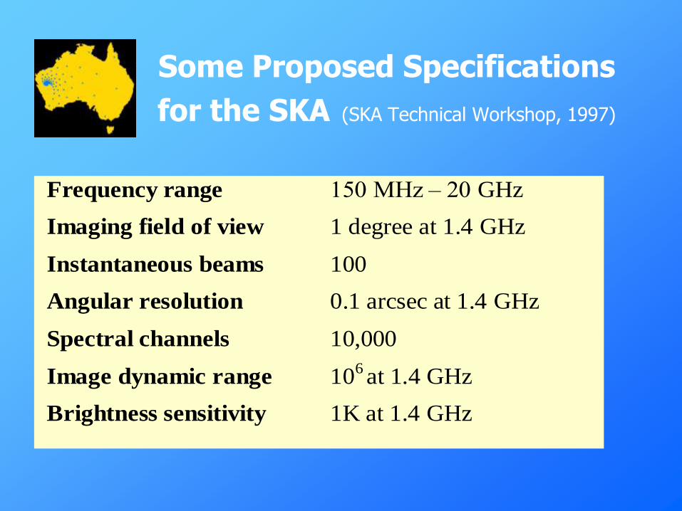
Some Proposed Specifications
for the SKA (SKA Technical Workshop, 1997)
Frequency range 150 MHz – 20 GHz
Imaging field of view 1 degree at 1.4 GHz
Instantaneous beams 100
Angular resolution 0.1 arcsec at 1.4 GHz
Spectral channels 10,000
Image dynamic range 106 at 1.4 GHz
Brightness sensitivity 1K at 1.4 GHz
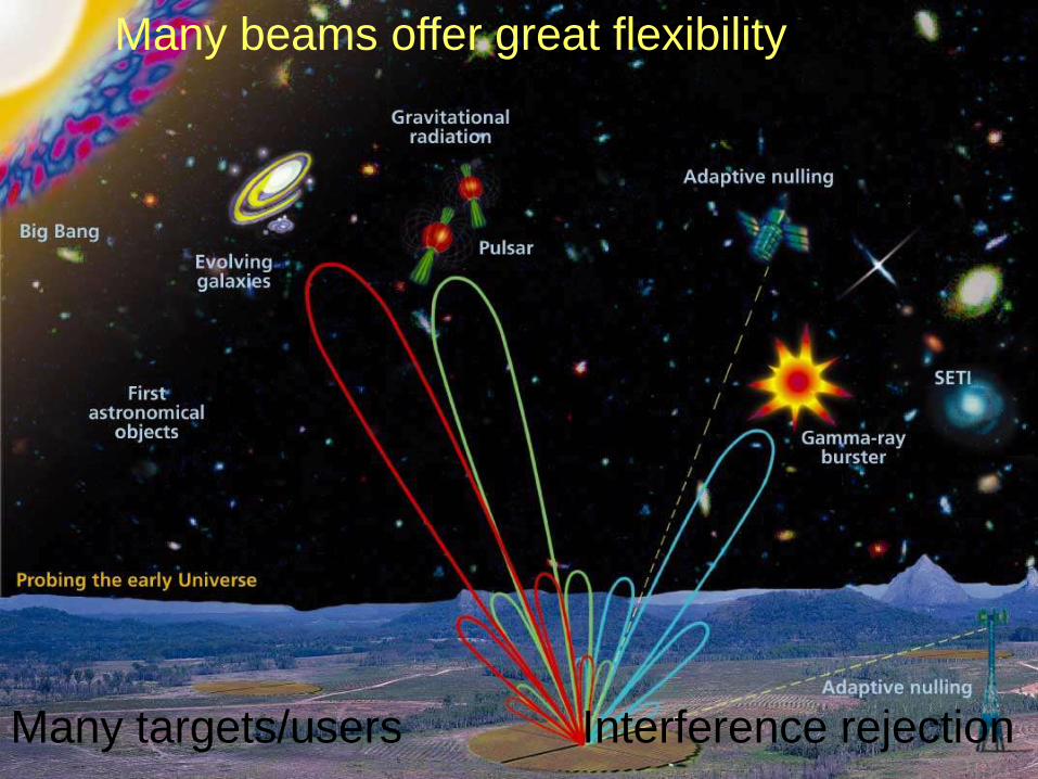
SKA poster (multi-beams)
Many beams offer great flexibility
Many targets/users Interference rejection
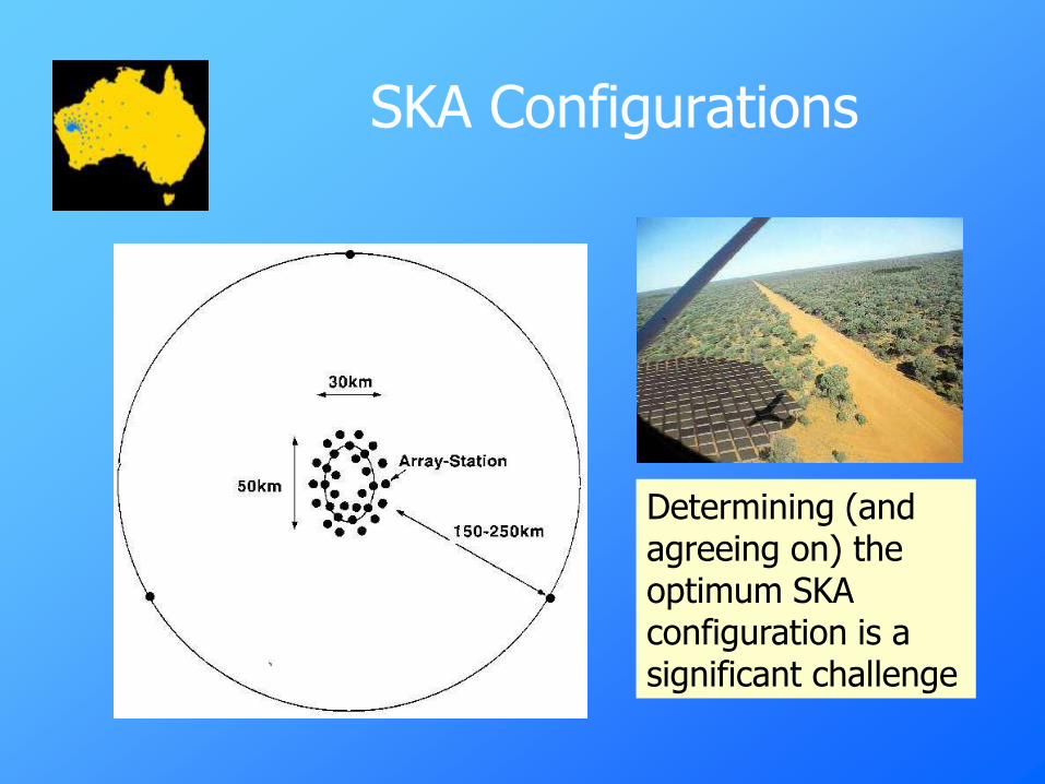
SKA Configurations
Determining (and agreeing on) the optimum SKA configuration is a significant challenge
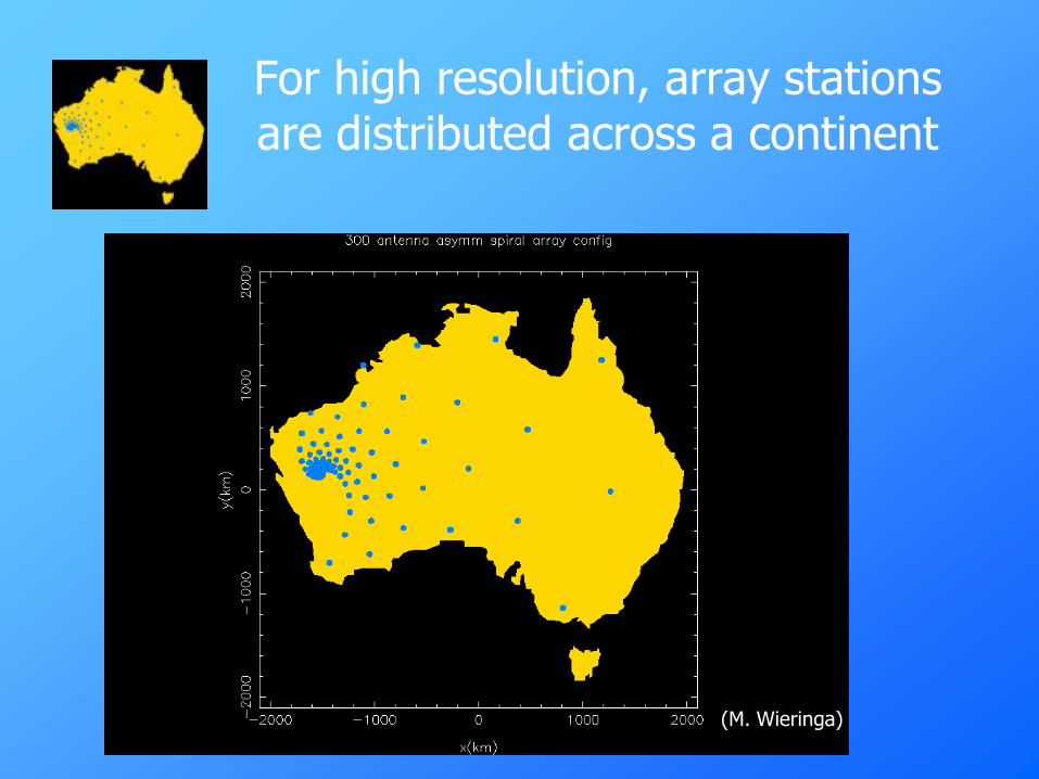
For high resolution, array stations are distributed across a continent
(M. Wieringa)
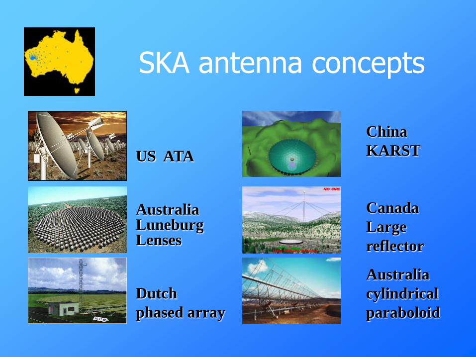
US ATA
Australia Luneburg Lenses
Dutch
phased array
SKA antenna concepts
China
KARST
Canada
Large
reflector
Australia
cylindrical
paraboloid

Parabolic Reflector Array (SETI Institute, USA)

Phased array conceptReplace mechanical pointing, beam forming
by electronic means
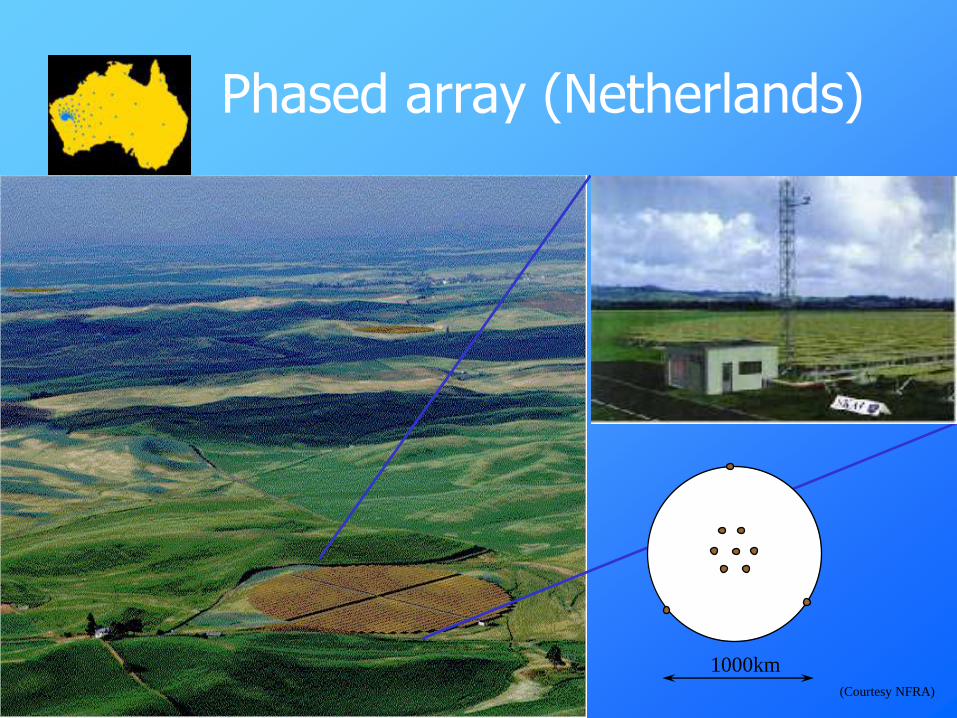
Phased array (Netherlands)
1000km
(Courtesy NFRA)

• A collimated beam is
focussed onto the
other side of the
sphere
• Beam can come from
any direction
Luneburg Lens
• Spherical lens with
variable permittivity
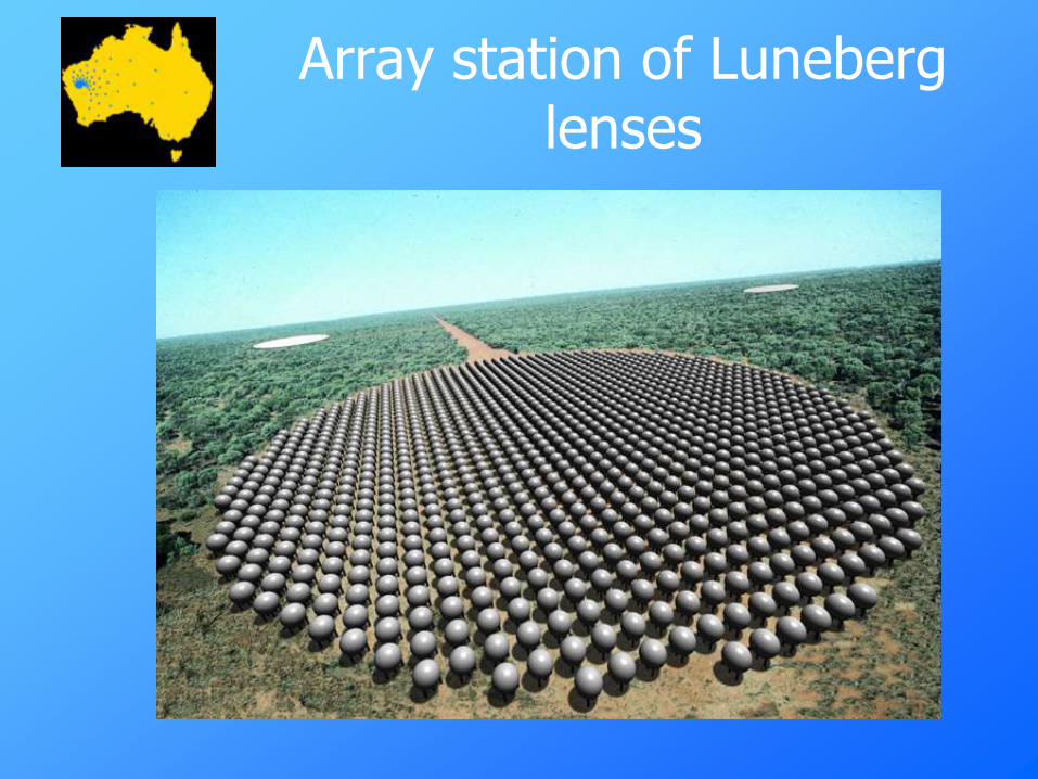
Array station of Luneberg lenses
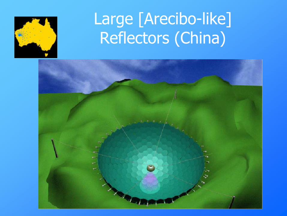
Large [Arecibo-like] Reflectors (China)
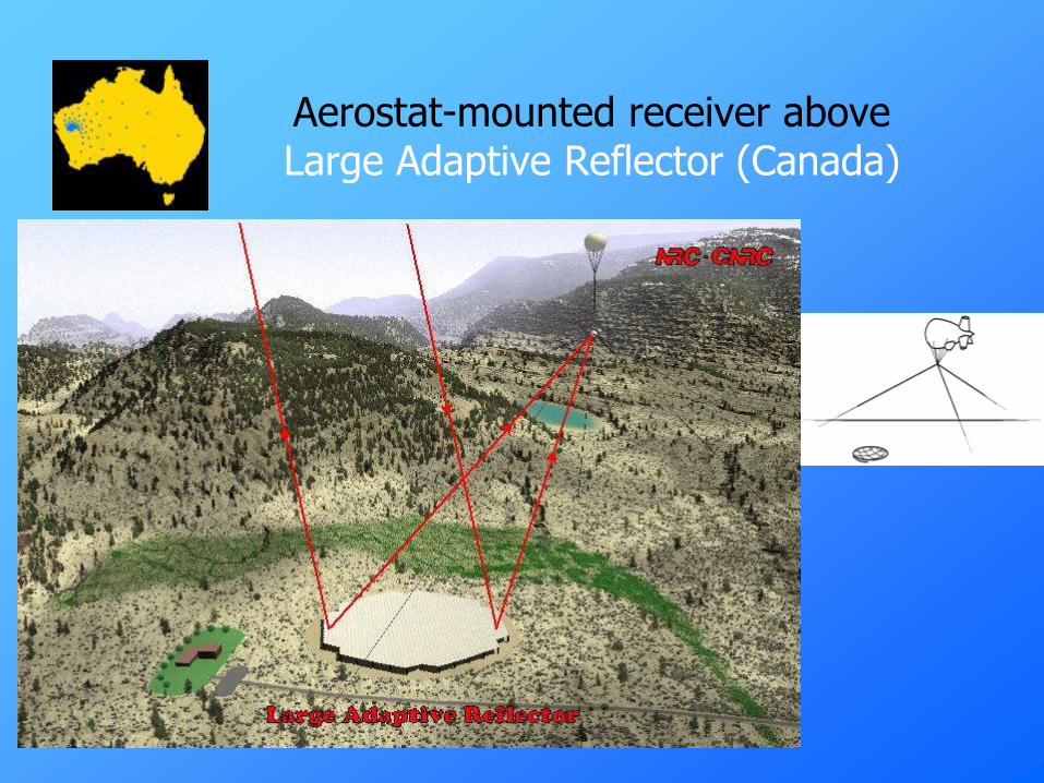
Aerostat-mounted receiver aboveLarge Adaptive Reflector (Canada)
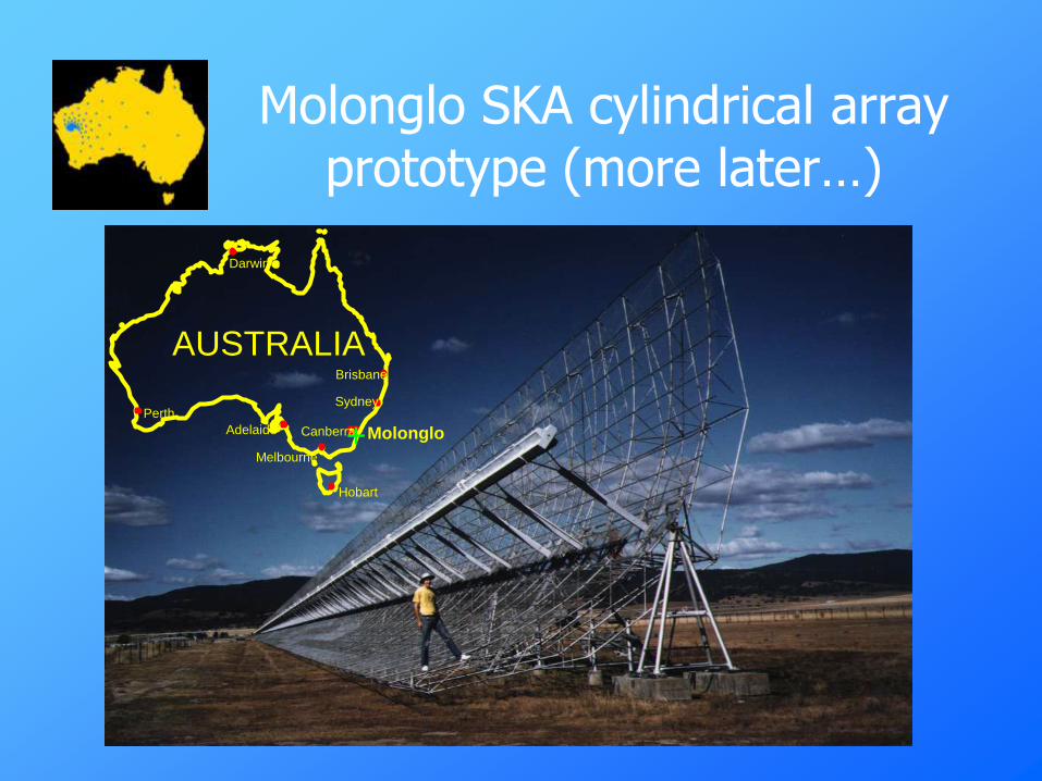
Molonglo SKA cylindrical array prototype (more later…)
Molonglo
AUSTRALIABrisbane
Darwin
Perth
Canberra
Hobart
Adelaide
Melbourne
Sydney
+
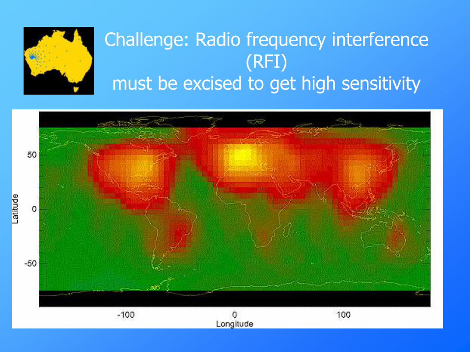
Challenge: Radio frequency interference (RFI)
must be excised to get high sensitivity

SKA Science Goals
• “The driving ambition for this new facility… is
no less than to chart a complete history of time”(Taylor & Braun 1999)
• Structure and kinematics of the universe before galaxy formation
• Formation and evolution of galaxies
• Understanding key astrophysical processes in star formation and planetary formation
• Tests of general relativity, etc.

SKA science: A concise history of the Universe
Dark
Ages
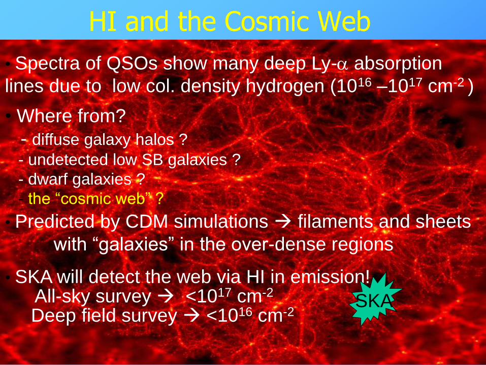
HI and the Cosmic Web
• Spectra of QSOs show many deep Ly-a absorption
lines due to low col. density hydrogen (1016 –1017 cm-2 )
• Predicted by CDM simulations filaments and sheets
with “galaxies” in the over-dense regions
• SKA will detect the web via HI in emission!All-sky survey <1017 cm-2
Deep field survey <1016 cm-2
• Where from?
- diffuse galaxy halos ?
- undetected low SB galaxies ?
- dwarf galaxies ?
- the “cosmic web” ?
SKA
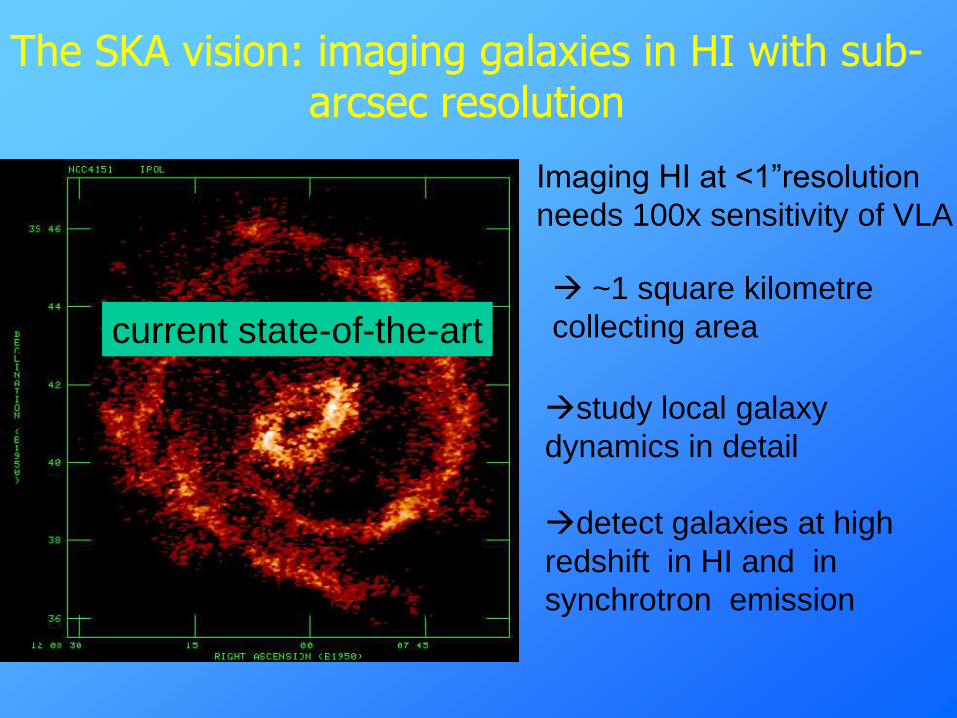
The SKA vision: imaging galaxies in HI with sub-arcsec resolution
Imaging HI at <1”resolution
needs 100x sensitivity of VLA
~1 square kilometre
collecting area
study local galaxy
dynamics in detail
detect galaxies at high
redshift in HI and in
synchrotron emission
NGC 4151 VLA 18 hours
HI at 5 arcsec resolution
current state-of-the-art
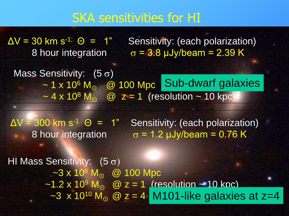
SKA sensitivities for HI
ΔV = 30 km s-1; Θ = 1”
8 hour integration
Sensitivity: (each polarization)
s = 3.8 μJy/beam = 2.39 K
Mass Sensitivity: (5 s)
~ 1 x 10⁶ M
@ 100 Mpc
~ 4 x 10⁸ M
@ z = 1 (resolution ~ 10 kpc)
ΔV = 300 km s-1 Θ = 1”
8 hour integration
Sensitivity: (each polarization)
s = 1.2 μJy/beam = 0.76 K
HI Mass Sensitivity: (5 s)
~3 x 10⁶ M
@ 100 Mpc
~1.2 x 10⁹ M
@ z = 1 (resolution ~ 10 kpc)
~3 x 10¹⁰ M
@ z = 4 M101-like galaxies at z=4
Sub-dwarf galaxies
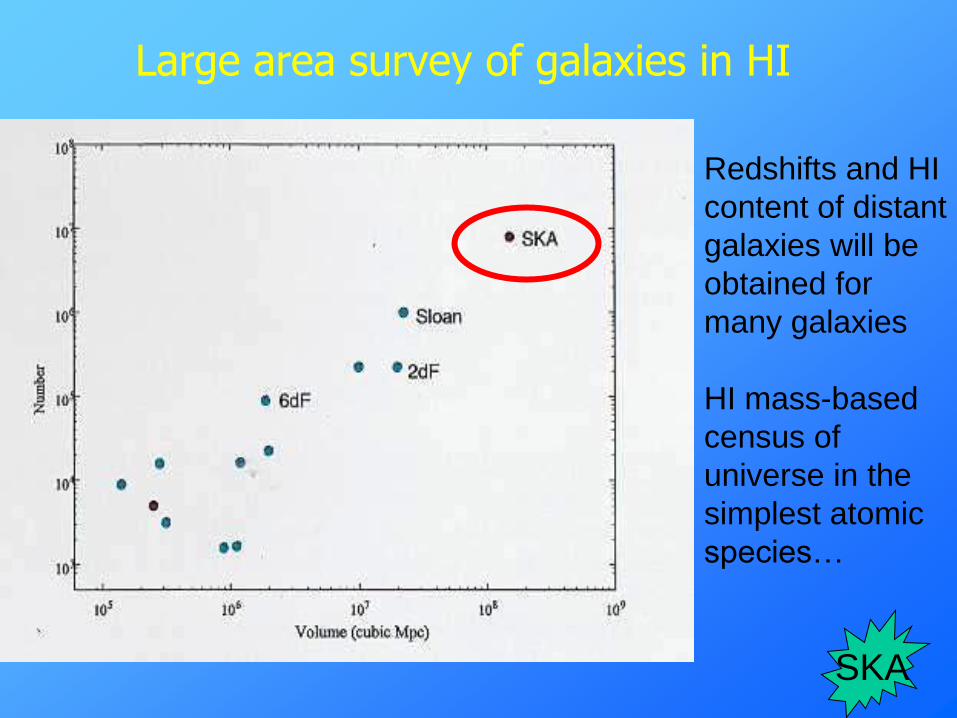
Large area survey of galaxies in HI
Redshifts and HI
content of distant
galaxies will be
obtained for
many galaxies
HI mass-based
census of
universe in the
simplest atomic
species…
SKA
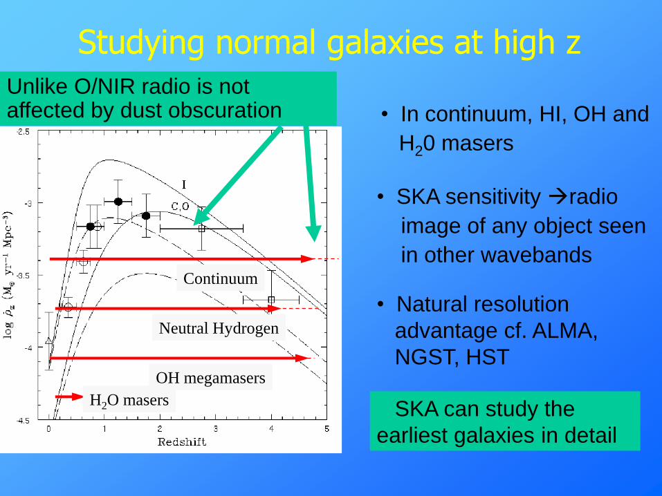
Neutral Hydrogen
Continuum
• In continuum, HI, OH and
H20 masers
Unlike O/NIR radio is not affected by dust obscuration
• Natural resolution
advantage cf. ALMA,
NGST, HST
• SKA sensitivity radio
image of any object seen
in other wavebands
Studying normal galaxies at high z
H2O masers
OH megamasers
SKA can study the
earliest galaxies in detail
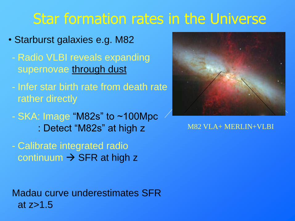
Star formation rates in the Universe
M82 VLA+ MERLIN+VLBI
• Starburst galaxies e.g. M82
- Radio VLBI reveals expanding
supernovae through dust
- Infer star birth rate from death rate
rather directly
- SKA: Image “M82s” to ~100Mpc
: Detect “M82s” at high z
- Calibrate integrated radio
continuum SFR at high z
Madau curve underestimates SFR
at z>1.5
M82 optical
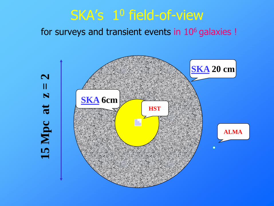
SKA‟s 10 field-of-viewfor surveys and transient events in 106 galaxies !
HST
SKA 6cm
ALMA
15
Mp
c a
t z
= 2
SKA 20 cm
2001 MNRF funding for Australian SKA developments
August 2001: Major National Research Facilities funding -$23.5 million for astronomy (SKA and Gemini) 2001-5
Main SKA-related projects:
• Two „demonstrator‟ array patches (Luneberg lenses or tiles) to be
built at or near Narrabri and linked to ATCA
• New wide-band correlator for ATCA
• Swinburne University - supercomputing and simulations for SKA
• University of Sydney - prototype cylindrical paraboloid antenna, digital signal processing, wide-band correlator for Molonglo
Stepping stones to SKA: Prototype SKA technologies at Molonglo
Joint project between the University of Sydney, Australia Telescope National Facility and CSIRO Telecommunications and Industrial Physics. Funded in 2001 Major National Research Facilities scheme.
Goal: To equip the Molonglo telescope with new feeds, low-noise amplifiers, digital filterbank and FX correlator with the joint aims of (i) developing and testing SKA-relevant technologies and (ii) providing a new national research facility for low-frequency radio astronomy
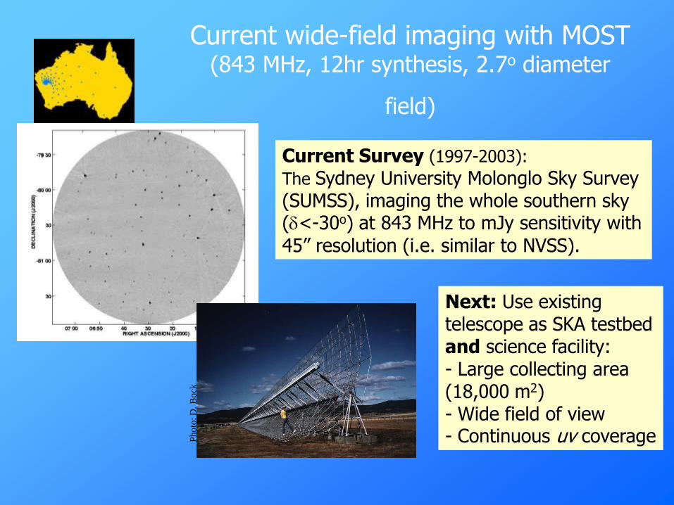
Current wide-field imaging with MOST (843 MHz, 12hr synthesis, 2.7o diameter
field)
Current Survey (1997-2003):
The Sydney University Molonglo Sky Survey (SUMSS), imaging the whole southern sky (d<-30o) at 843 MHz to mJy sensitivity with 45” resolution (i.e. similar to NVSS).
Next: Use existing telescope as SKA testbed and science facility: - Large collecting area (18,000 m2) - Wide field of view - Continuous uv coverageP
ho
to: D
. B
ock

Cylindrical paraboloid: Continuous uv coverage gives excellent image quality
Continuous uv coverage from 90 m to 1.6 km in 12hr synthesis
SKA will also have fully-sampled uv data
1.6 km
750 m
(Bock et al. 1999)

Key features of the Molonglo SKA prototype
Multibeaming
Wide instantaneous field of view
Digital beamforming
Wide-band FX correlator (2048 channels)
Frequency and pointing agility
Collecting area = 1% of SKA (i.e. equivalent to 1 SKA station)
Wide-band line feeds and LNAs
Cylindrical antenna prototype
Adaptive null steering and adaptive noise cancellation

Signal Path and Antenna Pattern
Cylindrical Parabolic Collectors (Two collinear 778 m x 12 m)
300-1420 MHz Feed and LNA(7,400 feeds, 14,800 LNAs)
Delay line beamforming
Analog to Digital Converter(1,600 8 bit 250 MHz BW ADCs)
Digital delay beamforming(80 x10 m x 10 m patches)
Digital filterbank (160)
(Two polarisations @ 250 MHz/patch)
FX Correlator(3,160 baselines, 2,048 channels)
Signal processing & storage(imaging, spectrometer, searching...)
Independent fanbeam
Digital Beamformer(64 fanbeams within imaging beam)
[Requires extra funding]
Single feed beam
Delay line beam
Independent fanbeam
Imaging beam
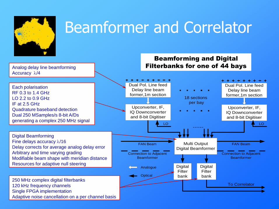
Beamformer and Correlator
Dual Pol. Line feed
Delay line beam
former,1m section
Upconverter, IF,
IQ Downconverter
and 8-bit Digitiser
Dual Pol. Line feed
Delay line beam
former,1m section
Upconverter, IF,
IQ Downconverter
and 8-bit Digitiser
18 sections
per bay
Multi Output
Digital Beamformer
Digital
Filter
bank
FAN Beam
Connection to Adjacent
Beamformer
FAN Beam
Connection to Adjacent
Beamformer
Digital
Filter
bank
To Correlator
Analogue
Optical
LO LO
Analog delay line beamforming
Accuracy /4
Each polarisation
RF 0.3 to 1.4 GHz
LO 2.2 to 0.9 GHz
IF at 2.5 GHz
Quadrature baseband detection
Dual 250 MSamples/s 8-bit A/Ds
generating a complex 250 MHz signal
Digital Beamforming
Fine delays accuracy /16
Delay corrects for average analog delay error
Arbitrary and time varying grading
Modifiable beam shape with meridian distance
Resources for adaptive null steering
250 MHz complex digital filterbanks
120 kHz frequency channels
Single FPGA implementation
Adaptive noise cancellation on a per channel basis
Beamforming and Digital
Filterbanks for one of 44 bays
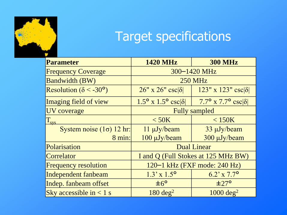
Target specifications
33 μJy/beam
300 μJy/beam
< 150K
±27°±6°Indep. fanbeam offset
1000 deg2180 deg2Sky accessible in < 1 s
6.2’ x 7.7°1.3’ x 1.5°Independent fanbeam
120–1 kHz (FXF mode: 240 Hz)Frequency resolution
I and Q (Full Stokes at 125 MHz BW)Correlator
Dual LinearPolarisation
11 μJy/beam
100 μJy/beam
System noise (1σ) 12 hr:
8 min:
< 50KTsys
300–1420 MHzFrequency Coverage
250 MHzBandwidth (BW)
Fully sampledUV coverage
7.7° x 7.7° csc|δ|1.5° x 1.5° csc|δ|Imaging field of view
123" x 123" csc|δ|26" x 26" csc|δ|Resolution (δ < -30°)
300 MHz1420 MHzParameter

Science goals: 1. High-redshift radio galaxies
FX correlator: wide-band radio spectrometry
Radio spectral index measurements over the range 300 –1400 MHz are an efficient way of selecting high-redshift (z>3) radio galaxies (e.g. de Breuck et al. 2000).
Radio galaxy TN0924-2201 at z=5.19
(van Breugel et al. 1999)
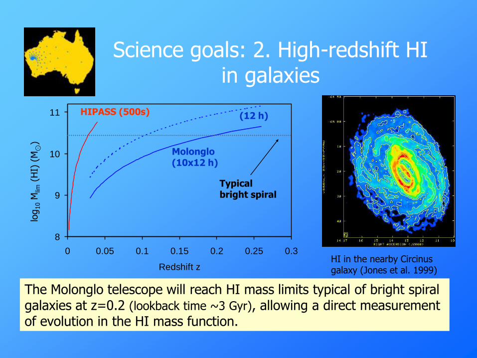
Science goals: 2. High-redshift HI in galaxies
8
9
10
11
0 0.05 0.1 0.15 0.2 0.25 0.3
Redshift z
HIPASS (500s)
Molonglo (10x12 h)
(12 h)
log
10
Mlim
(HI)
(M⊙
)
Typical bright spiral
HI in the nearby Circinus galaxy (Jones et al. 1999)
The Molonglo telescope will reach HI mass limits typical of bright spiral galaxies at z=0.2 (lookback time ~3 Gyr), allowing a direct measurement of evolution in the HI mass function.
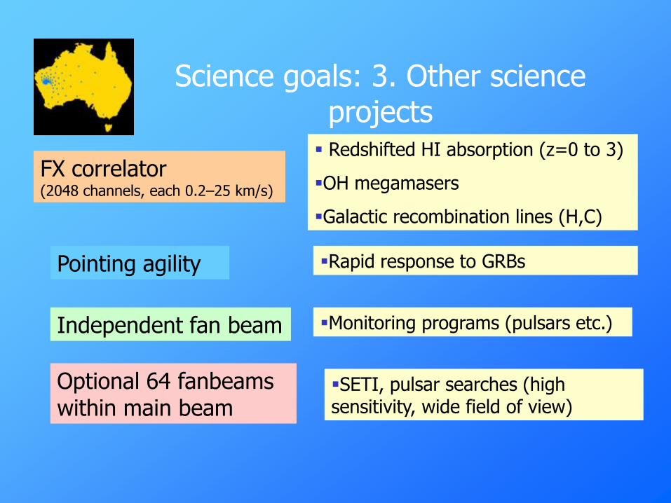
Science goals: 3. Other science projects
FX correlator (2048 channels, each 0.2–25 km/s)
Redshifted HI absorption (z=0 to 3)
OH megamasers
Galactic recombination lines (H,C)
Pointing agility Rapid response to GRBs
Independent fan beam Monitoring programs (pulsars etc.)
Optional 64 fanbeams within main beam
SETI, pulsar searches (high sensitivity, wide field of view)

RFI at Molonglo 200-1500 MHz (Measured 25 June 2001)
-115
-105
-95
-85
-75
0 500 1000 1500
Frequency (MHz)
Me
asu
red
Po
we
r (d
Bm
)
GSM
VHF
TV
UHF
TV
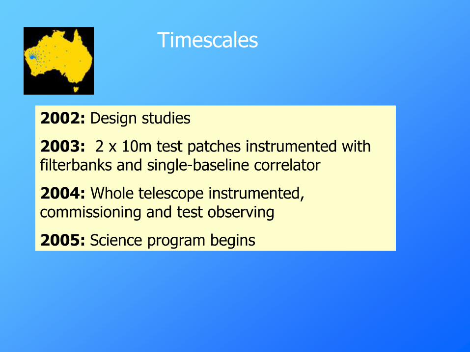
Timescales
2002: Design studies
2003: 2 x 10m test patches instrumented with filterbanks and single-baseline correlator
2004: Whole telescope instrumented, commissioning and test observing
2005: Science program begins

• 2000 ISSC formed (Europe; US; Australia, Canada, China, India)
• 2002 Management plan established
• 2005 Agreement on technical implementation and site
• 2008 SKA scientific and technical proposal completed
• 2010 SKA construction begins ?
• 2015 SKA completed ?
SKA schedule