
Sizing Electric Motors for Mobile Robotics
35
May 21, 2006 Sizing Electric Motors for Mobile Robotics
-
Upload
anon-293485 -
Category
Documents
-
view
654 -
download
91
Transcript of Sizing Electric Motors for Mobile Robotics

May 21, 2006
Sizing Electric Motors for Mobile Robotics

May 21, 2006
The Basics
May 21, 2006
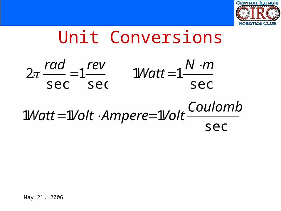
Unit Conversions
sec1
sec2 revrad
sec
11 mNWatt
sec111 CoulombVoltAmpereVoltWatt
May 21, 2006
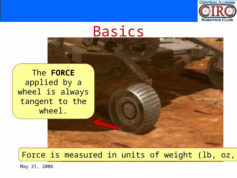
Basics
The FORCE applied by a wheel is always tangent to the wheel.
Force is measured in units of weight (lb, oz, N)
May 21, 2006
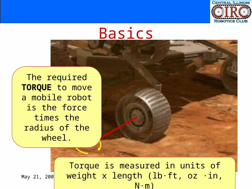
Basics
The required TORQUE to move a mobile robot is the
force times the radius of the wheel.
Torque is measured in units of weight x length (lb·ft, oz ·in, N·m)
May 21, 2006
Procedure for Sizing DC Motors
May 21, 2006
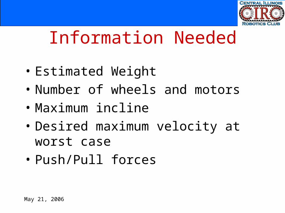
Information Needed
• Estimated Weight• Number of wheels and motors• Maximum incline• Desired maximum velocity at worst
case• Push/Pull forces
May 21, 2006
Procedure
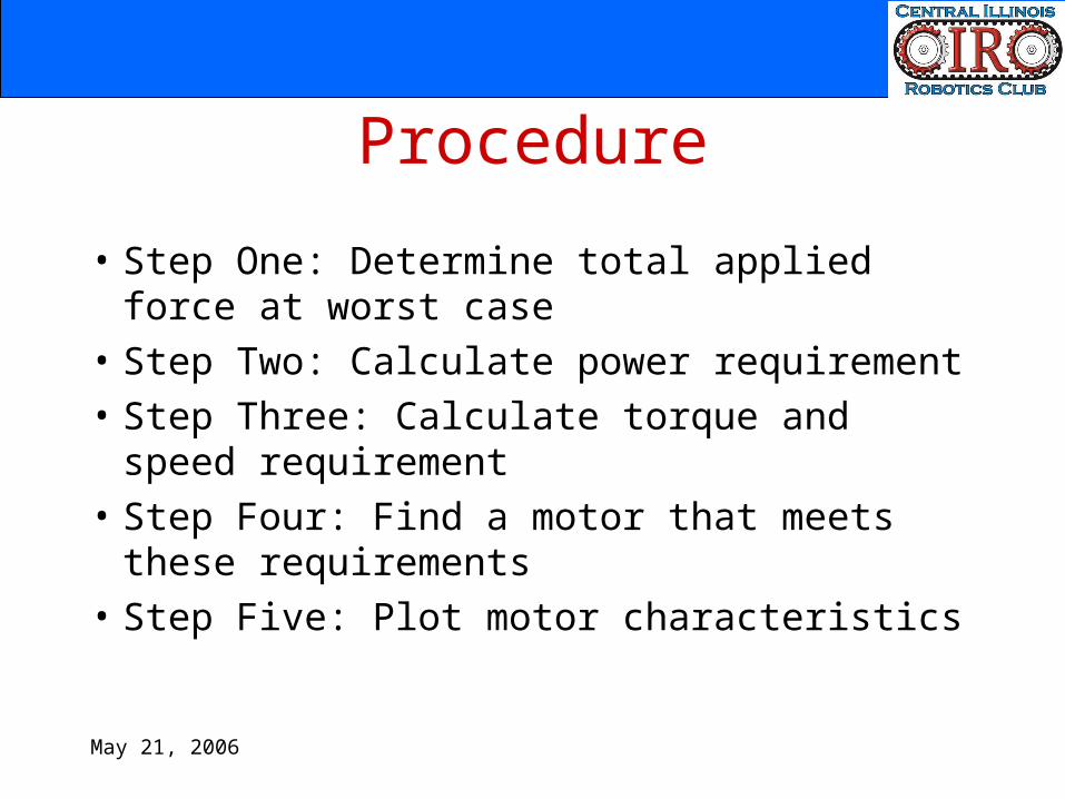
• Step One: Determine total applied force at worst case
May 21, 2006
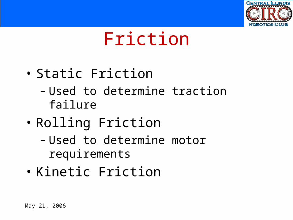
Friction
• Static Friction– Used to determine traction failure
• Rolling Friction– Used to determine motor requirements
• Kinetic Friction
May 21, 2006
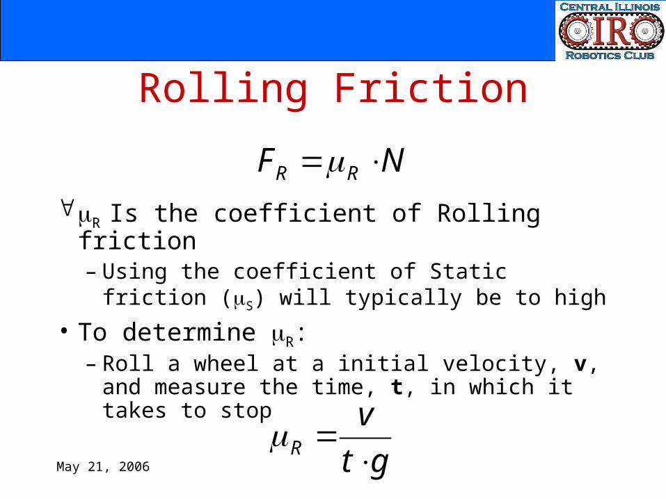
Rolling Friction
R Is the coefficient of Rolling friction– Using the coefficient of Static friction (S)
will typically be to high• To determine R:
– Roll a wheel at a initial velocity, v, and measure the time, t, in which it takes to stop
NF RR
gtv
R

May 21, 2006
Rolling Friction
• Some typical values for R
– Steel on steel: 0.001– Rubber on pavement: 0.015
May 21, 2006
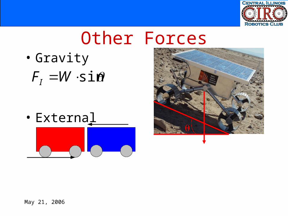
Other Forces
sinWFI
• Gravity
• External
May 21, 2006
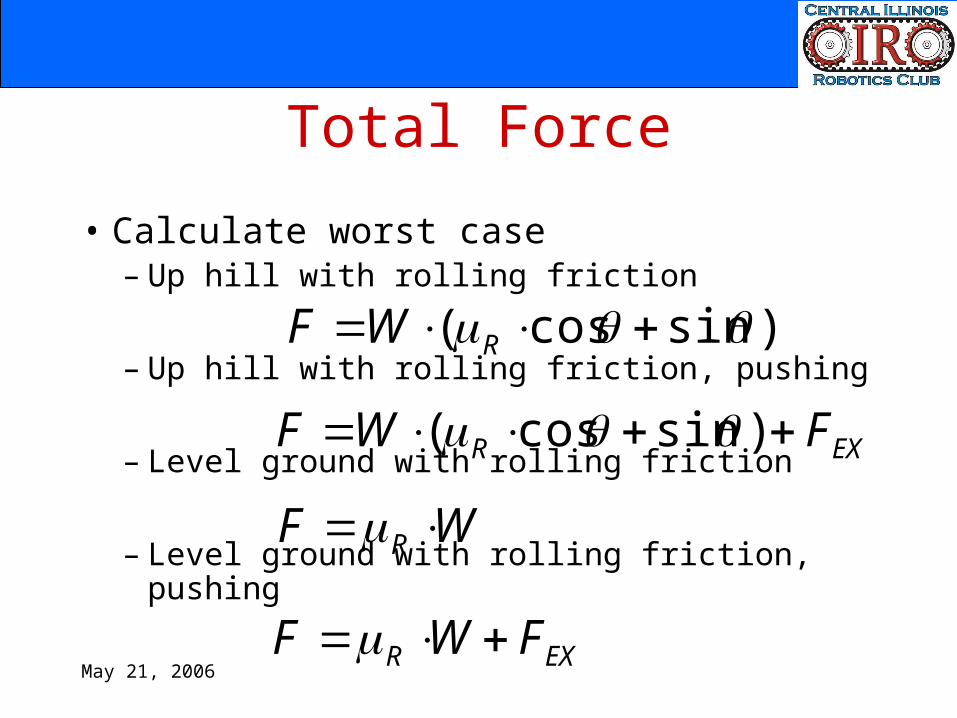
Total Force
• Calculate worst case– Up hill with rolling friction
– Up hill with rolling friction, pushing
– Level ground with rolling friction
– Level ground with rolling friction, pushing
)sincos( RWF
EXR FWF )sincos(
WF R
EXR FWF
May 21, 2006
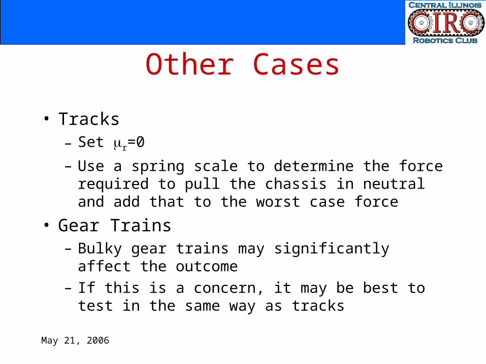
Other Cases
• Tracks– Set r=0– Use a spring scale to determine the force required to
pull the chassis in neutral and add that to the worst case force
• Gear Trains– Bulky gear trains may significantly affect the outcome– If this is a concern, it may be best to test in the same
way as tracks
May 21, 2006
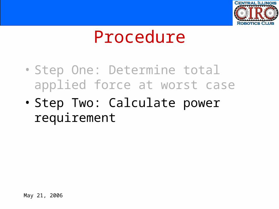
Procedure
• Step One: Determine total applied force at worst case
• Step Two: Calculate power requirement
May 21, 2006
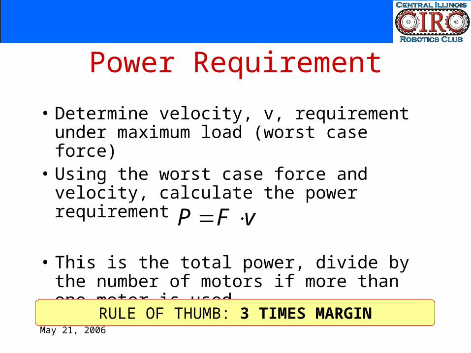
Power Requirement
• Determine velocity, v, requirement under maximum load (worst case force)
• Using the worst case force and velocity, calculate the power requirement
• This is the total power, divide by the number of motors if more than one motor is used
vFP
RULE OF THUMB: 3 TIMES MARGIN
May 21, 2006
Procedure
• Step One: Determine total applied force at worst case
• Step Two: Calculate power requirement• Step Three: Calculate torque and speed
requirement
May 21, 2006
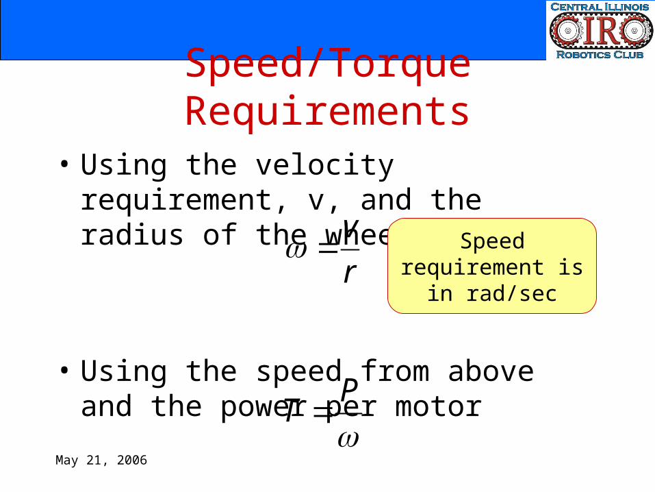
Speed/Torque Requirements
• Using the velocity requirement, v, and the radius of the wheel, r
• Using the speed from above and the power per motor
rv
Speed requirement is in rad/sec
PT
May 21, 2006
Procedure
• Step One: Determine total applied force at worst case
• Step Two: Calculate power requirement• Step Three: Calculate torque and speed
requirement• Step Four: Find a motor that meets
these requirements
May 21, 2006
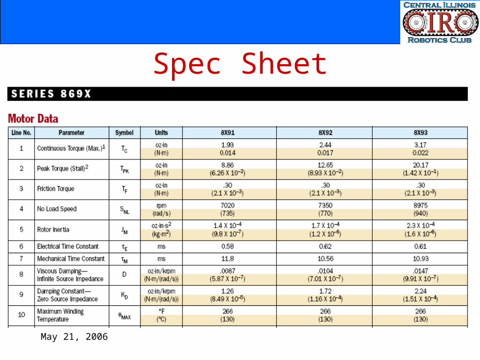
Spec Sheet
May 21, 2006
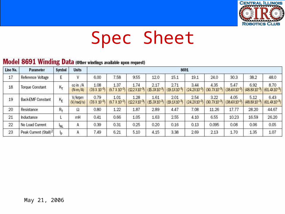
Spec Sheet
May 21, 2006
Procedure
• Step One: Determine total applied force at worst case
• Step Two: Calculate power requirement• Step Three: Calculate torque and speed
requirement• Step Four: Find a motor that meets these
requirements• Step Five: Plot motor characteristics
May 21, 2006
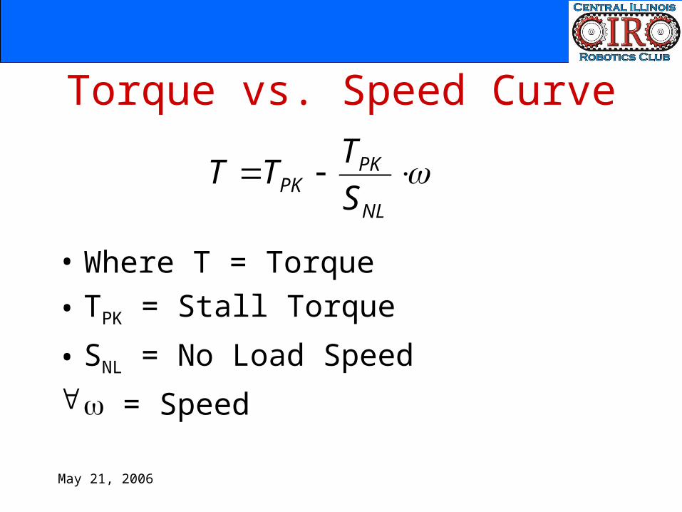
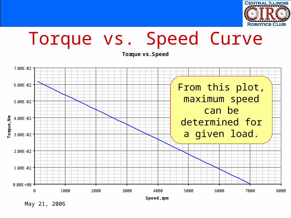
Torque vs. Speed Curve
• Where T = Torque• TPK = Stall Torque
• SNL = No Load Speed = Speed
NL
PKPK S
TTT
May 21, 2006
Torque vs. Speed CurveTorque vs. Speed
0.00E+00
1.00E-02
2.00E-02
3.00E-02
4.00E-02
5.00E-02
6.00E-02
7.00E-02
0 1000 2000 3000 4000 5000 6000 7000 8000
Speed, rpm
Torq
ue, N
m
From this plot, maximum speed can be determined for a
given load.
May 21, 2006
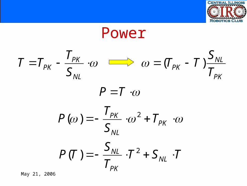
Power
NL
PKPK S
TTTPK
NLPK T
STT )(
TP
PKNL
PK TSTP 2)(
TSTTSTP NLPK
NL 2)(
May 21, 2006
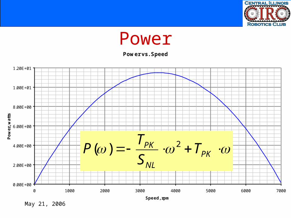
PowerPower vs. Speed
0.00E+00
2.00E+00
4.00E+00
6.00E+00
8.00E+00
1.00E+01
1.20E+01
0 1000 2000 3000 4000 5000 6000 7000
Speed, rpm
Pow
er, w
atts
PKNL
PK TSTP 2)(
May 21, 2006
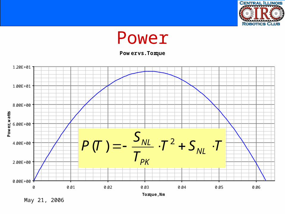
PowerPower vs. Torque
0.00E+00
2.00E+00
4.00E+00
6.00E+00
8.00E+00
1.00E+01
1.20E+01
0 0.01 0.02 0.03 0.04 0.05 0.06
Torque, Nm
Pow
er, w
atts
TSTTSTP NLPK
NL 2)(

May 21, 2006
PowerPower vs. Speed
0.00E+00
2.00E+00
4.00E+00
6.00E+00
8.00E+00
1.00E+01
1.20E+01
0 1000 2000 3000 4000 5000 6000 7000
Speed, rpm
Pow
er, w
atts
Power vs. Torque
0.00E+00
2.00E+00
4.00E+00
6.00E+00
8.00E+00
1.00E+01
1.20E+01
0 0.01 0.02 0.03 0.04 0.05 0.06
Torque, Nm
Pow
er, w
atts
max21TT
max21
Peak power is obtained at half of maximum torque and speed
May 21, 2006
Procedure
• Step One: Determine total applied force at worst case
• Step Two: Calculate power requirement• Step Three: Calculate torque and speed
requirement• Step Four: Find a motor that meets these
requirements• Step Five: Plot motor characteristics

May 21, 2006
A Few Extra Points
May 21, 2006
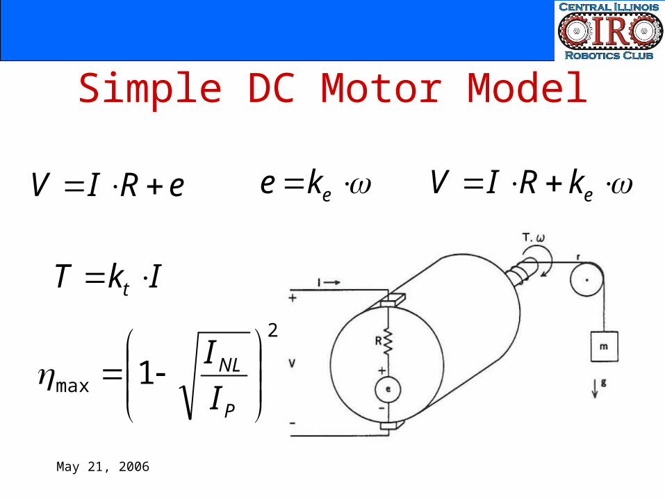
Simple DC Motor Model
eRIV eke ekRIV
IkT t 2
max 1
P
NL
II
May 21, 2006
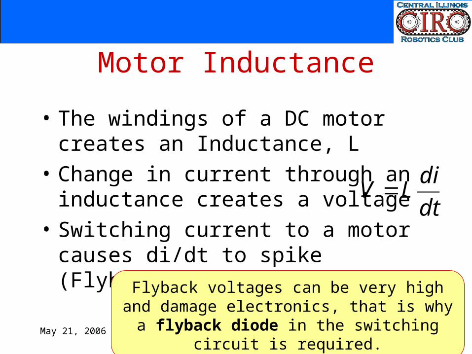
Motor Inductance
• The windings of a DC motor creates an Inductance, L
• Change in current through an inductance creates a voltage
• Switching current to a motor causes di/dt to spike (Flyback)
dtdiLV
Flyback voltages can be very high and damage electronics, that is why a flyback diode in the
switching circuit is required.
May 21, 2006
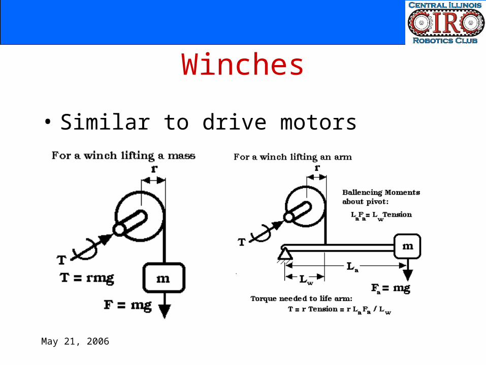
Winches
• Similar to drive motors
May 21, 2006
Common Mistakes
• Using static or kinetic friction instead of rolling friction– If a wheel is rolling without slipping, the only
energy loss is due to deformations in the wheel/surface (rolling friction)
• Using PWM to control a motor reduces the available torque– The average power, speed and torque are
reduced, however, effective torque is not significantly effected

May 21, 2006
Questions?