SITRANS RD500 - Siemens · PDF fileSITRANS RD500 OPC Connectivity AG102710 2 of 12 Configuring...
12
Siemens Milltronics Process Instruments Inc. 1954 Technology Drive, P.O. Box 4225 Peterborough, Ontario K9J 7B1 / Canada Tel.: (705) 745-2431 Fax: (705) 741-0466 www.siemens.com/processautomation AG102710 SITRANS RD500 OPC connectivity with Kepware OPC server Objective: 1. To connect the SITRANS RD500 to an OPC server via Modbus TCP. 2. To read/write process tags from the SITRANS RD500 when connected to an OPC server. Equipment: • SITRANS RD500 • RDDO14R digital input card • Modbus serial device (MR200) • RS485 cable to connect the MR200 to the RD500 • PC with Ethernet connection and KepServerEX OPC server software V4.201 While every effort was made to verify the following information, no warranty of accuracy or usability is expressed or implied. Overview This application guide is an addition to the operating instructions. Please review the operating instructions for the RD500 Application and for the RD500 Hardware to ensure you are familiar with configuring the SITRANS RD500. OPC Software This application guide explains how to use OPC to read the status of several devices connected to a SITRANS RD500. OPC, which stands for OLE for Process Control, is an open standard for communication of real-time data between industrial devices from different manufacturers. OPC servers provide a way for different types of Windows-based software to access data from a process control device, such as a PLC or DCS. The OPC server software resides on a PC or server and connects to devices in a number of different ways depending on the protocol driver type, for example serial, modem or Ethernet. The OPC server polls the connected devices for the requested data as configured in the OPC server’s tag database. The data is then made available for an OPC client to read. It is also possible for an OPC client to write data to the OPC server’s tag database. OPC client connectivity may be from a SCADA application, for example WinCC, or any other software package which has OPC client connectivity. The diagram at the right illustrates one possible application of OPC. APPLICATION GUIDE
Transcript of SITRANS RD500 - Siemens · PDF fileSITRANS RD500 OPC Connectivity AG102710 2 of 12 Configuring...
Siemens Milltronics Process Instruments Inc.
1954 Technology Drive, P.O. Box 4225 Peterborough, Ontario K9J 7B1 / Canada
Tel.: (705) 745-2431 Fax: (705) 741-0466 www.siemens.com/processautomation
AG102710
SITRANS RD500
OPC connectivity with Kepware OPC server
Objective: 1. To connect the SITRANS RD500 to an OPC server via Modbus TCP. 2. To read/write process tags from the SITRANS RD500 when connected to an OPC server.
Equipment: • SITRANS RD500 • RDDO14R digital input card • Modbus serial device (MR200)
• RS485 cable to connect the MR200 to the RD500 • PC with Ethernet connection and KepServerEX OPC
server software V4.201
While every effort was made to verify the following information, no warranty of accuracy or usability is expressed or implied.
Overview
This application guide is an addition to the operating instructions. Please review the operating instructions for the RD500 Application and for the RD500 Hardware to ensure you are familiar with configuring the SITRANS RD500.
OPC Software
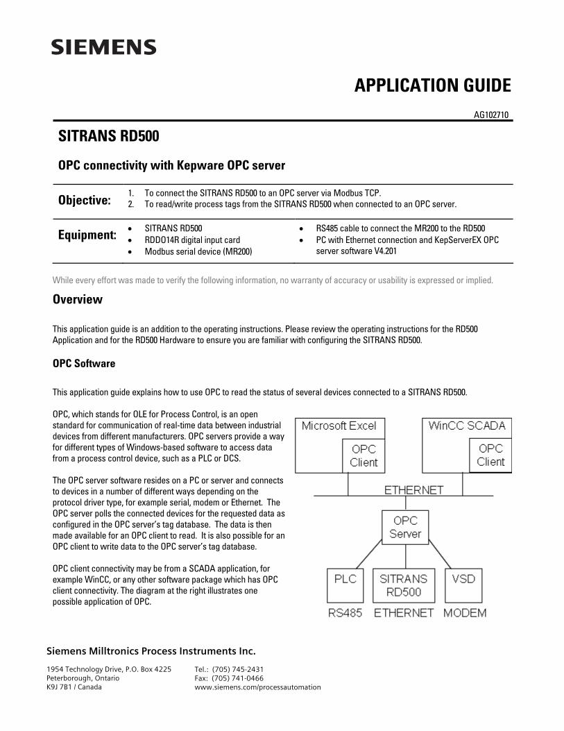
This application guide explains how to use OPC to read the status of several devices connected to a SITRANS RD500. OPC, which stands for OLE for Process Control, is an open standard for communication of real-time data between industrial devices from different manufacturers. OPC servers provide a way for different types of Windows-based software to access data from a process control device, such as a PLC or DCS. The OPC server software resides on a PC or server and connects to devices in a number of different ways depending on the protocol driver type, for example serial, modem or Ethernet. The OPC server polls the connected devices for the requested data as configured in the OPC server’s tag database. The data is then made available for an OPC client to read. It is also possible for an OPC client to write data to the OPC server’s tag database. OPC client connectivity may be from a SCADA application, for example WinCC, or any other software package which has OPC client connectivity. The diagram at the right illustrates one possible application of OPC.
APPLICATION GUIDE

SITRANS RD500 OPC Connectivity AG102710 2 of 12
Configuring the SITRANS RD500
This guide assumes that the I/O devices shown in the Modbus slave mapping table below have been connected to the RD500 and configured appropriately using the RD500 web application. The Modbus slave mapping can be viewed within the application by selecting (from the Overview page) Configure > I/O > Modbus and then clicking on the Slave Mapping button at the bottom of the screen.
This application guide explains how to connect the SITRANS RD500 to KepServerEX OPC server software. It also explains how to use the OPC server to configure tags to display the LG200 level, and to control the valve and the pump shown in the Modbus Slave Mapping table in the image above.
Configuring the OPC Server
This guide assumes that you are using KepServerEX version 4.201 as your OPC server software. KepServerEX is available from http://www.kepware.com.
Adding a New Channel to the OPC Server
The first step in connecting the SITRANS RD500 to the OPC server via Modbus is to add a new channel to the OPC server. The following procedure explains how.
1. Start KepServerEX from the desktop or Start Menu. Click New on the menu bar. A window called KEPServerEx – [untitled.opf] will open.
SITRANS RD500 OPC Connectivity AG102710 3 of 12
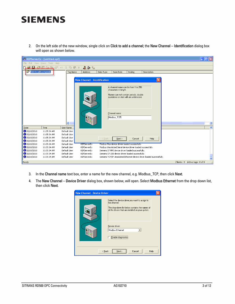
2. On the left side of the new window, single click on Click to add a channel; the New Channel – Identification dialog box will open as shown below.
3. In the Channel name text box, enter a name for the new channel, e.g. Modbus_TCP, then click Next.
4. The New Channel – Device Driver dialog box, shown below, will open. Select Modbus Ethernet from the drop down list, then click Next.

SITRANS RD500 OPC Connectivity AG102710 4 of 12
5. All remaining New Channel dialog boxes should be left at their default settings for this application, as shown below. After checking the values for each step, click the Next button.
a. Network Interface
b. Write Optimizations
c. Socket Usage

SITRANS RD500 OPC Connectivity AG102710 5 of 12
6. You should now be at the New Channel – Summary dialog box as shown below.
7. Use the Back button to make any necessary changes, and then click Finish to complete the new channel setup. You have now added a channel called Modbus_TCP to your OPC server. This new channel appears in the left hand side of the KEPServerEx window.
Adding a New Device to a Channel
After adding the Modbus_TCP channel to KepServer, the RD500 can be added as a new device using the following procedure.
1. On the left side of the KEPServerEx window, under the channel name Modbus_TCP, single click on Click to add a device; the New Device – Name dialog box will open as shown below.

SITRANS RD500 OPC Connectivity AG102710 6 of 12
2. In the Device name text box, enter a name for the new device, e.g. RD500, then click Next.
3. The New Device – Model dialog box, shown below, will open. Select Modbus from the drop down list, and then click Next.
4. The New Device – ID dialog box will open. Enter the IP address for the remote SITRANS RD500 and then click Next.

SITRANS RD500 OPC Connectivity AG102710 7 of 12
5. All remaining New Device dialog boxes should be left at their default settings for this application, as shown below. After checking the values for each step, click the Next button.
a. Data Access Settings
b. Data Encoding Settings
c. Timing

SITRANS RD500 OPC Connectivity AG102710 8 of 12
d. Auto-Demotion
e. Database Creation
f. TCP/IP
SITRANS RD500 OPC Connectivity AG102710 9 of 12
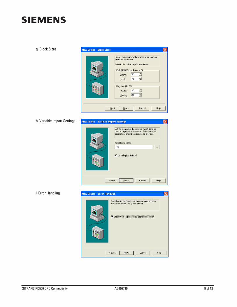
g. Block Sizes
h. Variable Import Settings
i. Error Handling

SITRANS RD500 OPC Connectivity AG102710 10 of 12
6. You should now be at the New Device – Summary dialog box, as shown below.
7. Use the Back button to make any necessary changes, and then click Finish to complete the new device setup. You have
now added the RD500 to the Modbus_TCP channel of your OPC server. This new device appears in the left hand side of the KEPServerEx window.
Configuring Process Tags
Now that the SITRANS RD500 has been connected to the OPC server, KepServerEX can be used to configure process tags of various kinds. The following procedure explains how to use the OPC server to configure tags to control the valve and the pump, and to display the LG200 level, as shown in the Modbus Slave Mapping image on page 2.
1. Single click on Click to add new tag in the tag list to the right of the channel and device list.

SITRANS RD500 OPC Connectivity AG102710 11 of 12
2. The Tag Properties dialog box will open. 3. Enter the following tag information and then click OK.
• Name: Control • Address: 400001 • Description: control of valve and pump • Data type: Word • Client access: Read/Write • Scan rate: 100
4. Repeat steps 1, 2 and 3 to create a tag to display the LG200 level using the following information:
• Name: LG200 Level • Address: 400002 • Description: level from the LG200 • Data type: Word • Client access: Read only • Scan rate: 100
The newly created tags will appear in the list of tags as shown below. Note that the icons to the left of the tag names indicate that Control is a Read/Write tag and LG200 Level is read only.
5. On the main toolbar, click File > Save and save your work as RD500.opf.
SITRANS RD500 OPC Connectivity AG102710 12 of 12
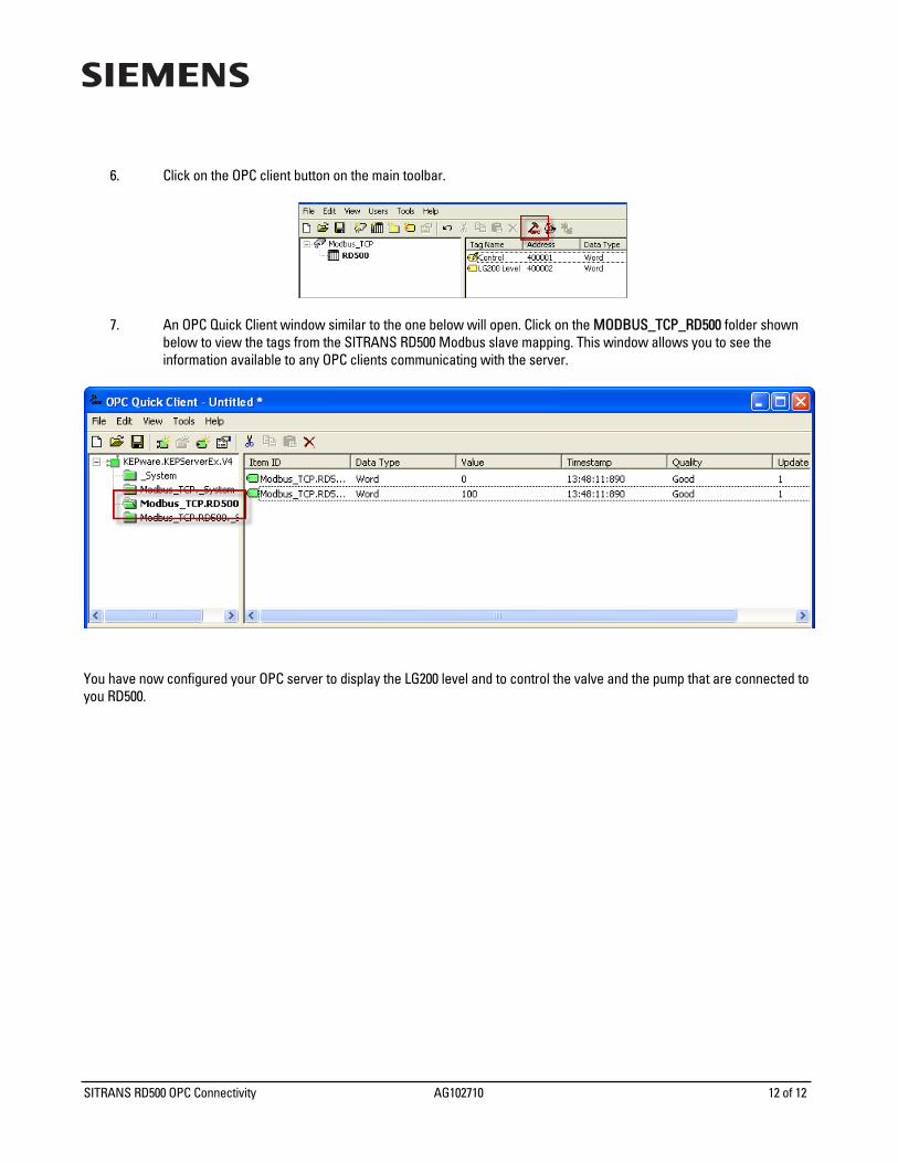
6. Click on the OPC client button on the main toolbar.
7. An OPC Quick Client window similar to the one below will open. Click on the MODBUS_TCP_RD500 folder shown below to view the tags from the SITRANS RD500 Modbus slave mapping. This window allows you to see the information available to any OPC clients communicating with the server.
You have now configured your OPC server to display the LG200 level and to control the valve and the pump that are connected to you RD500.