SITRANS LR250 (FOUNDATION FIELDBUS)
306
Operating Instructions SITRANS LR250 (Foundation Fieldbus) 08/2014 Edition Radar Transmitters
Transcript of SITRANS LR250 (FOUNDATION FIELDBUS)

Operating Instructions
SITRANS LR250 (Foundation Fieldbus)
08/2014Edition
Radar Transmitters
© Siemens AG 2013
Safety Guidelines
Warning notices must be observed to ensure personal safety as well as that of others, and to protect the product and the connected equipment.
These warning notices are accompanied by a clarification of the level of caution to be observed.
Qualified Personnel
This device/system may only be set up and operated in conjunction with this manual. Qualified personnel are only authorized to install and
operate this equipment in accordance with established safety practices and standards.
Unit Repair and Excluded Liability:
The user is responsible for all changes and repairs made to the device by the user or the user’s agent.
All new components are to be provided by Siemens Milltronics Process Instruments.
Restrict repair to faulty components only.
Do not reuse faulty components.
Warning: Cardboard shipping package provides limited humidity and moisture protection. This product can only function properly and safely if
it is correctly transported, stored, installed, set up, operated, and maintained.
This product is intended for use in industrial areas. Operation of this equipment in a residential area may cause interference to several
frequency based communications.
Note: Always use product in accordance with specifications.
Copyright Siemens AG 2013. All Rights Reserved Disclaimer of Liability
This document is available in bound version and in
electronic version. We encourage users to purchase
authorized bound manuals, or to view electronic versions as
designed and authored by Siemens Milltronics Process
Instruments. Siemens Milltronics Process Instruments will
not be responsible for the contents of partial or whole
reproductions of either bound or electronic versions.
While we have verified the contents of this
manual for agreement with the instrumentation
described, variations remain possible. Thus we
cannot guarantee full agreement. The contents of
this manual are regularly reviewed and
corrections are included in subsequent editions.
We welcome all suggestions for improvement.
Technical data subject to change.
MILLTRONICS®is a registered trademark of Siemens Milltronics Process Instruments.
Contact SMPI Technical Publications European Authorized Representative
at the following address: Technical Publications Siemens AG
Siemens AG Industry Sector
Siemens Milltronics Process Instruments 76181 Karlsruhe
1954 Technology Drive, P.O. Box 4225 Deutschland
Peterborough, Ontario, Canada, K9J 7B1
Email: [email protected]
For a selection of Siemens Milltronics level measurement manuals, go to:
www. siemens.com/processautomation. Under Process Instrumentation, select Level Measurement and then go to the manual archive
listed under the product family.
For a selection of Siemens Milltronics weighing manuals, go to:
www. siemens.com/processautomation. Under Weighing Technology, select Continuous Weighing Systems and then go to the manual
archive listed under the product family.

SITRANS LR250 (FOUNDATION
FIELDBUS)
___________________
___________________
___________________
___________________
___________________
___________________
___________________
___________________
___________________
___________________
___________________
___________________
___________________
___________
___________________
___________________
___________________
SITRANS
Radar Transmitters SITRANS LR250 (FOUNDATION FIELDBUS)
Operating Instructions
08/2014 A5E32221411-AC
Introduction
1
Safety information
2
Description
3
Installing/mounting
4
Connecting
5
Commissioning
6
Remote operation
7
Parameter reference
8
Service and maintenance
9
Diagnosing and troubleshooting
10
Technical data
11
Dimension drawings
12
Appendix A: Technical reference
A
Appendix B: Communications via Foundation Fieldbus
B
Appendix C: Certificates and support
C
List of abbreviations
13
LCD menu structure
14

Siemens AG Industry Sector Postfach 48 48 90026 NÜRNBERG GERMANY
Order number: A5E32221411 Ⓟ 06/2014 Subject to change
Copyright © Siemens AG 2014. All rights reserved
Legal information
Warning notice system This manual contains notices you have to observe in order to ensure your personal safety, as well as to prevent damage to property. The notices referring to your personal safety are highlighted in the manual by a safety alert symbol, notices referring only to property damage have no safety alert symbol. These notices shown below are graded according to the degree of danger.
DANGER
indicates that death or severe personal injury will result if proper precautions are not taken.
WARNING
indicates that death or severe personal injury may result if proper precautions are not taken.
CAUTION
indicates that minor personal injury can result if proper precautions are not taken.
NOTICE
indicates that property damage can result if proper precautions are not taken.
If more than one degree of danger is present, the warning notice representing the highest degree of danger will be used. A notice warning of injury to persons with a safety alert symbol may also include a warning relating to property damage.
Qualified Personnel The product/system described in this documentation may be operated only by personnel qualified for the specific task in accordance with the relevant documentation, in particular its warning notices and safety instructions. Qualified personnel are those who, based on their training and experience, are capable of identifying risks and avoiding potential hazards when working with these products/systems.
Proper use of Siemens products Note the following:
WARNING
Siemens products may only be used for the applications described in the catalog and in the relevant technical documentation. If products and components from other manufacturers are used, these must be recommended or approved by Siemens. Proper transport, storage, installation, assembly, commissioning, operation and maintenance are required to ensure that the products operate safely and without any problems. The permissible ambient conditions must be complied with. The information in the relevant documentation must be observed.
Trademarks All names identified by ® are registered trademarks of Siemens AG. The remaining trademarks in this publication may be trademarks whose use by third parties for their own purposes could violate the rights of the owner.
Disclaimer of Liability We have reviewed the contents of this publication to ensure consistency with the hardware and software described. Since variance cannot be precluded entirely, we cannot guarantee full consistency. However, the information in this publication is reviewed regularly and any necessary corrections are included in subsequent editions.

SITRANS LR250 (FOUNDATION FIELDBUS)
Operating Instructions, 08/2014, A5E32221411-AC 3
Table of contents
1 Introduction ............................................................................................................................................. 9
1.1 LR250 FF manual usage ............................................................................................................... 9
1.2 Purpose of this documentation ...................................................................................................... 9
1.3 Document history ........................................................................................................................... 9
1.4 Firmware revision history ............................................................................................................. 10
1.5 Designated use ............................................................................................................................ 10
1.6 Checking the consignment ........................................................................................................... 10
1.7 Transportation and storage .......................................................................................................... 11
1.8 Notes on warranty ........................................................................................................................ 11
2 Safety information ................................................................................................................................. 13
2.1 Preconditions for safe use ........................................................................................................... 13 2.1.1 Safety marking symbols ............................................................................................................... 13 2.1.2 Laws and directives ..................................................................................................................... 13 2.1.3 FCC Conformity ........................................................................................................................... 13 2.1.4 Conformity with European directives ........................................................................................... 14 2.1.5 CE Electromagnetic Compatibility (EMC) Conformity.................................................................. 15
2.2 Improper device modifications ..................................................................................................... 15
2.3 Requirements for special applications ......................................................................................... 16
2.4 Use in hazardous areas ............................................................................................................... 16
3 Description ............................................................................................................................................ 19
3.1 SITRANS LR250 overview ........................................................................................................... 19
3.2 Programming ................................................................................................................................ 20
3.3 Applications .................................................................................................................................. 20
3.4 Approvals and certificates ............................................................................................................ 20
4 Installing/mounting ................................................................................................................................ 21
4.1 Basic safety information ............................................................................................................... 21 4.1.1 Pressure applications ................................................................................................................... 22 4.1.1.1 Pressure Equipment Directive, PED, 97/23/EC ........................................................................... 23
4.2 Installation location requirements ................................................................................................ 24
4.3 Proper mounting........................................................................................................................... 26 4.3.1 Nozzle design ............................................................................................................................... 27

Table of contents
SITRANS LR250 (FOUNDATION FIELDBUS)
4 Operating Instructions, 08/2014, A5E32221411-AC
4.3.2 Nozzle location ............................................................................................................................ 28 4.3.3 Orientation in a vessel with obstructions ..................................................................................... 31 4.3.4 Mounting on a Stillpipe or Bypass Pipe ...................................................................................... 32 4.3.5 Device orientation ....................................................................................................................... 33
4.4 Installation instructions ................................................................................................................ 34 4.4.1 Threaded versions ...................................................................................................................... 36 4.4.2 Flanged versions ......................................................................................................................... 37 4.4.3 Hygienic versions ........................................................................................................................ 39
4.5 Disassembly ................................................................................................................................ 40
5 Connecting ............................................................................................................................................41
5.1 Basic safety information .............................................................................................................. 41
5.2 Connecting SITRANS LR250 ...................................................................................................... 41
5.3 Wiring setups for hazardous area installation ............................................................................. 45 5.3.1 Configuration with Foundation Fieldbus for hazardous areas .................................................... 46 5.3.2 Intrinsically safe wiring ................................................................................................................ 47 5.3.2.1 Intrinsically safe wiring (FM/CSA) ............................................................................................... 48 5.3.3 Non-sparking wiring .................................................................................................................... 50 5.3.4 Non-incendive wiring (US/Canada only) ..................................................................................... 50
5.4 Instructions specific to hazardous area installations ................................................................... 51 5.4.1 (Reference European ATEX Directive 94/9/EC, Annex II, 1/0/6) ............................................... 51
6 Commissioning ......................................................................................................................................53
6.1 Basic safety information .............................................................................................................. 53
6.2 Operating via the handheld programmer .................................................................................... 53 6.2.1 Power up ..................................................................................................................................... 54 6.2.2 Handheld programmer functions ................................................................................................. 54 6.2.2.1 The LCD display .......................................................................................................................... 55 6.2.2.2 Handheld programmer (Part No. 7ML1930-1BK) ....................................................................... 57 6.2.3 Programming ............................................................................................................................... 58 6.2.3.1 Quick Start Wizard via the handheld programmer_note ............................................................. 63 6.2.3.2 Auto False Echo Suppression ..................................................................................................... 66 6.2.3.3 Requesting an Echo Profile ........................................................................................................ 67 6.2.3.4 Device Address ........................................................................................................................... 68
6.3 Application examples .................................................................................................................. 68 6.3.1 Liquid resin in storage vessel, level measurement ..................................................................... 69 6.3.2 Horizontal vessel with volume measurement.............................................................................. 70 6.3.3 Application with stillpipe .............................................................................................................. 72
7 Remote operation ..................................................................................................................................75
7.1 Operating via AMS Device Manager ........................................................................................... 75 7.1.1 Functions in AMS Device Manager ............................................................................................. 75 7.1.2 Key features of AMS Device Manager Rev. 9.0 ......................................................................... 77 7.1.2.1 Pull-down menu access .............................................................................................................. 78

Table of contents
SITRANS LR250 (FOUNDATION FIELDBUS)
Operating Instructions, 08/2014, A5E32221411-AC 5
7.1.3 Adding a new device .................................................................................................................... 78 7.1.3.1 Electronic Device Description (EDD) ........................................................................................... 78 7.1.4 Master Reset ................................................................................................................................ 80 7.1.5 Scan Device ................................................................................................................................. 80 7.1.6 Sensor calibration ........................................................................................................................ 81 7.1.7 Configuring a new device ............................................................................................................. 81 7.1.7.1 Quick Start Wizard via AMS Device Manager ............................................................................. 81 7.1.8 Changing parameter settings using AMS Device Manager ......................................................... 87 7.1.9 Configure/Setup (Level Transducer Block-LTB) .......................................................................... 88 7.1.9.1 Identification (LTB) ....................................................................................................................... 88 7.1.9.2 Operation (LTB) ........................................................................................................................... 89 7.1.9.3 Setup (LTB) .................................................................................................................................. 91 7.1.9.4 Linearization (LTB) ....................................................................................................................... 93 7.1.9.5 Signal processing ......................................................................................................................... 95 7.1.9.6 Maintenance & Diagnostics (LTB) ............................................................................................. 100 7.1.9.7 Communication (LTB) ................................................................................................................ 103 7.1.10 Configure/Setup (Liquid Crystal Display Block-LCD)................................................................. 103 7.1.10.1 Identification (LCD) .................................................................................................................... 103 7.1.10.2 Operation (LCD) ......................................................................................................................... 104 7.1.10.3 Setup (LCD) ............................................................................................................................... 105 7.1.10.4 Communication (LCD) ............................................................................................................... 105 7.1.11 Configure/Setup (Diagnostic Transducer Block-DIAG) ............................................................. 106 7.1.11.1 Identification (DIAG) ................................................................................................................... 106 7.1.11.2 Operation (DIAG) ....................................................................................................................... 106 7.1.11.3 Communication (DIAG) .............................................................................................................. 106 7.1.12 Configure/Setup (Resource Block - RESOURCE) ..................................................................... 107 7.1.12.1 Identification (RESOURCE) ....................................................................................................... 107 7.1.12.2 Wizards (RESOURCE) .............................................................................................................. 108 7.1.12.3 Operation (RESOURCE) ........................................................................................................... 108 7.1.12.4 Maintenance & Diagnostics (RESOURCE) ............................................................................... 111 7.1.12.5 Communication (RESOURCE) .................................................................................................. 113 7.1.12.6 Security (RESOURCE) .............................................................................................................. 114 7.1.13 Device Diagnostics (Level Transducer Block - LTB) ................................................................. 114 7.1.13.1 Alarms & Errors (LTB) ................................................................................................................ 115 7.1.13.2 Extended Diagnostics (LTB) ...................................................................................................... 118 7.1.14 Device Diagnostics (Liquid Crystal Display Block - LCD) .......................................................... 119 7.1.14.1 Alarms & Errors (LCD) ............................................................................................................... 119 7.1.15 Device Diagnostics (Diagnostic Transducer Block - DIAG) ....................................................... 119 7.1.15.1 Alarms & Errors (DIAG) ............................................................................................................. 119 7.1.16 Device Diagnostics (Resource Block - RESOURCE) ................................................................ 119 7.1.16.1 Alarms & Errors (RESOURCE) .................................................................................................. 119 7.1.16.2 Extended Diagnostics (RESOURCE) ........................................................................................ 121 7.1.17 Process Variables (Level Transducer Block - LTB) ................................................................... 123 7.1.18 Password Protection .................................................................................................................. 124 7.1.18.1 User Manager utility ................................................................................................................... 124 7.1.19 AMS menu structure .................................................................................................................. 126

Table of contents
SITRANS LR250 (FOUNDATION FIELDBUS)
6 Operating Instructions, 08/2014, A5E32221411-AC
8 Parameter reference ............................................................................................................................ 139
8.1 Alphabetical parameter list ........................................................................................................ 186
9 Service and maintenance ..................................................................................................................... 191
9.1 Basic safety information ............................................................................................................ 191
9.2 Cleaning .................................................................................................................................... 191
9.3 Maintenance and repair work .................................................................................................... 192 9.3.1 Unit repair and excluded liability ............................................................................................... 193 9.3.2 Part replacement ....................................................................................................................... 193
9.4 Disposal .................................................................................................................................... 195
10 Diagnosing and troubleshooting ........................................................................................................... 197
10.1 Device status icons ................................................................................................................... 198
10.2 General fault codes ................................................................................................................... 199
10.3 Operation troubleshooting ......................................................................................................... 204
11 Technical data ..................................................................................................................................... 207
11.1 Power ........................................................................................................................................ 207
11.2 Performance .............................................................................................................................. 207
11.3 Interface .................................................................................................................................... 209
11.4 Mechanical ................................................................................................................................ 209
11.5 Environmental ........................................................................................................................... 212
11.6 Process ..................................................................................................................................... 212
11.7 Approvals .................................................................................................................................. 213
11.8 Programmer (infrared keypad) .................................................................................................. 214
12 Dimension drawings ............................................................................................................................. 215
12.1 Threaded horn antenna............................................................................................................. 215
12.2 Threaded horn antenna with extension ..................................................................................... 218
12.3 Flanged horn antenna ............................................................................................................... 220
12.4 Flanged horn antenna with extension ....................................................................................... 222
12.5 Flanged encapsulated antenna (2"/DN50/50A sizes only) ....................................................... 224
12.6 Flanged encapsulated antenna (3"/DN80/80A sizes and larger) .............................................. 226
12.7 Hygienic encapsulated antenna (2" ISO 2852 sanitary clamp) ................................................ 228
12.8 Hygienic encapsulated antenna (3" ISO 2852 sanitary clamp) ................................................ 229
12.9 Hygienic encapsulated antenna (4" ISO 2852 sanitary clamp) ................................................ 230
12.10 Hygienic encapsulated antenna (DN50 nozzle/ slotted nut to DIN 11851) ............................... 231

Table of contents
SITRANS LR250 (FOUNDATION FIELDBUS)
Operating Instructions, 08/2014, A5E32221411-AC 7
12.11 Hygienic encapsulated antenna (DN80 nozzle/ slotted nut to DIN 11851) ............................... 232
12.12 Hygienic encapsulated antenna (DN100 nozzle/ slotted nut to DIN 11851) ............................. 233
12.13 Hygienic encapsulated antenna (DN50 aseptic slotted nut to DIN 11864-1) ............................ 234
12.14 Hygienic encapsulated antenna (DN80 aseptic slotted nut to DIN 11864-1) ............................ 235
12.15 Hygienic encapsulated antenna (DN100 aseptic slotted nut to DIN 11864-1) .......................... 236
12.16 Hygienic encapsulated antenna (DN50 aseptic flange to DIN 11864-2) ................................... 237
12.17 Hygienic encapsulated antenna (DN80 aseptic flange to DIN 11864-2) ................................... 238
12.18 Hygienic encapsulated antenna (DN100 aseptic flange to DIN 11864-2) ................................. 239
12.19 Hygienic encapsulated antenna (DN50 aseptic clamp to DIN 11864-3) ................................... 240
12.20 Hygienic encapsulated antenna (DN80 aseptic clamp to DIN 11864-3) ................................... 241
12.21 Hygienic encapsulated antenna (DN100 aseptic clamp to DIN 11864-3) ................................. 242
12.22 Hygienic encapsulated antenna (Tuchenhagen Type N) .......................................................... 243
12.23 Hygienic encapsulated antenna (Tuchenhagen Type F) ........................................................... 244
12.24 Threaded PVDF antenna ........................................................................................................... 245
12.25 Threaded connection markings .................................................................................................. 246
12.26 Raised-Face flange per EN 1092-1 for flanged horn antenna ................................................... 247
12.27 Raised-Face flange per EN 1092-1 for flanged encapsulated antenna..................................... 249
12.28 Flat-Face flange ......................................................................................................................... 252
12.29 Aseptic/hygienic flange DN50, DN80, DN100 for DIN 11864-2 ................................................. 255
12.30 Process connection tag (pressure rated versions) .................................................................... 258
A Appendix A: Technical reference ......................................................................................................... 259
A.1 Principles of operation ............................................................................................................... 259
A.2 Echo processing......................................................................................................................... 260 A.2.1 Process Intelligence ................................................................................................................... 260 A.2.2 Echo Selection ........................................................................................................................... 261 A.2.3 CLEF Range .............................................................................................................................. 264 A.2.4 Measurement Response ............................................................................................................ 264 A.2.5 Echo Threshold .......................................................................................................................... 265 A.2.6 Echo Lock .................................................................................................................................. 265 A.2.7 Auto False Echo Suppression .................................................................................................... 265 A.2.8 Measurement Range ................................................................................................................. 267 A.2.9 Damping ..................................................................................................................................... 268 A.2.10 Loss of Echo (LOE) .................................................................................................................... 268 A.2.10.1 LOE Timer .................................................................................................................................. 268
A.3 Maximum Process Temperature Chart ...................................................................................... 269
A.4 Process Pressure/Temperature derating curves ....................................................................... 270
Table of contents
SITRANS LR250 (FOUNDATION FIELDBUS)
8 Operating Instructions, 08/2014, A5E32221411-AC
A.4.1 Pressure Equipment Directive, PED, 97/23/EC ........................................................................ 271 A.4.2 Horn antenna ............................................................................................................................ 271 A.4.3 Flanged horn antenna ............................................................................................................... 272 A.4.4 Flanged encapsulated antenna ................................................................................................. 277 A.4.5 PVDF antenna ........................................................................................................................... 279 A.4.6 Hygienic encapsulated antenna ................................................................................................ 280
B Appendix B: Communications via Foundation Fieldbus ........................................................................ 283
B.1 Field Communicator 375 (F375) ............................................................................................... 283
C Appendix C: Certificates and support ................................................................................................... 285
C.1 Certificates ................................................................................................................................ 285
C.2 Technical support ...................................................................................................................... 285
13 List of abbreviations ............................................................................................................................. 287
14 LCD menu structure ............................................................................................................................. 289
Glossary .............................................................................................................................................. 293
Index ................................................................................................................................................... 299

SITRANS LR250 (FOUNDATION FIELDBUS)
Operating Instructions, 08/2014, A5E32221411-AC 9
Introduction 1 1.1 LR250 FF manual usage
Note
This manual applies to the SITRANS LR250 (FOUNDATION™ Fieldbus) only. FOUNDATION™ Fieldbus is a trademark of Fieldbus Foundation.
Follow these operating instructions for quick, trouble-free installation, and maximum accuracy and reliability of your device.
We always welcome suggestions and comments about manual content, design, and accessibility. Please direct your comments to:
Technical publications (mailto:[email protected])
1.2 Purpose of this documentation
These instructions contain all information required to commission and use the device. It is your responsibility to read the instructions carefully prior to installation and commissioning. In order to use the device correctly, first review its principle of operation.
The instructions are aimed at persons mechanically installing the device, connecting it electronically, configuring the parameters and commissioning it, as well as service and maintenance engineers.
1.3 Document history
The following table notes major changes in the documentation compared to the previous edition.
Edition Remark
January 2014 • Flanged encapsulated antenna version added.
August 2014 • Hygienic encapsulated antenna version added.
Introduction
1.4 Firmware revision history
SITRANS LR250 (FOUNDATION FIELDBUS)
10 Operating Instructions, 08/2014, A5E32221411-AC
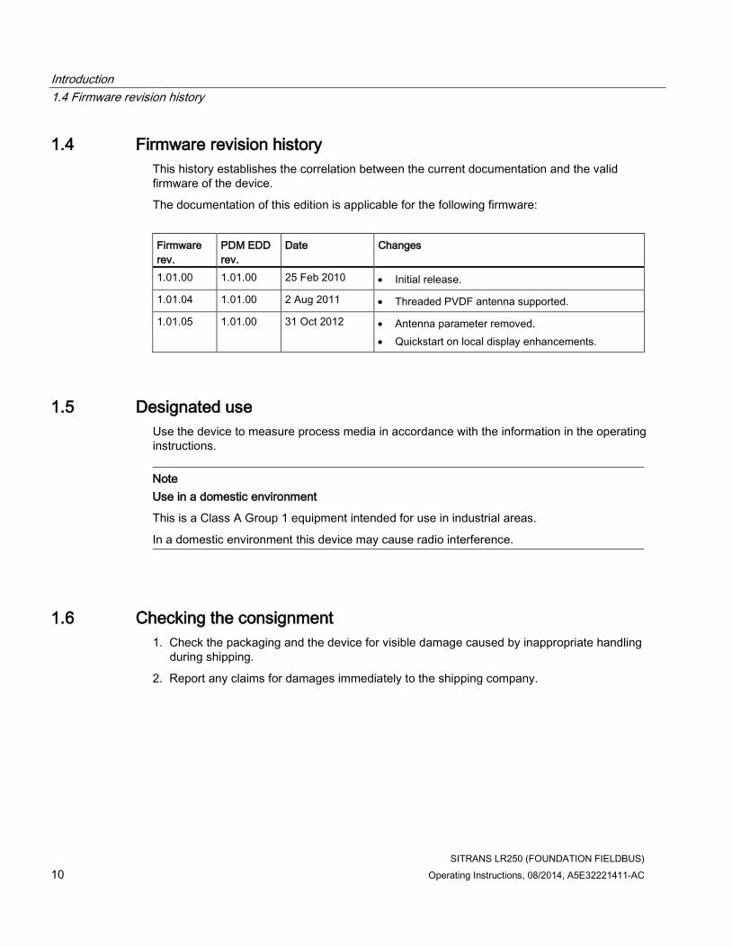
1.4 Firmware revision history
This history establishes the correlation between the current documentation and the valid firmware of the device.
The documentation of this edition is applicable for the following firmware:
Firmware rev.
PDM EDD rev.
Date Changes
1.01.00 1.01.00 25 Feb 2010 • Initial release.
1.01.04 1.01.00 2 Aug 2011 • Threaded PVDF antenna supported.
1.01.05 1.01.00 31 Oct 2012 • Antenna parameter removed.
• Quickstart on local display enhancements.
1.5 Designated use
Use the device to measure process media in accordance with the information in the operating instructions.
Note
Use in a domestic environment
This is a Class A Group 1 equipment intended for use in industrial areas.
In a domestic environment this device may cause radio interference.
1.6 Checking the consignment
1. Check the packaging and the device for visible damage caused by inappropriate handling during shipping.
2. Report any claims for damages immediately to the shipping company.

Introduction
1.7 Transportation and storage
SITRANS LR250 (FOUNDATION FIELDBUS)
Operating Instructions, 08/2014, A5E32221411-AC 11
3. Retain damaged parts for clarification.
4. Check the scope of delivery by comparing your order to the shipping documents for correctness and completeness.
WARNING
Using a damaged or incomplete device
Danger of explosion in hazardous areas.
• Do not use damaged or incomplete devices.
1.7 Transportation and storage
To guarantee sufficient protection during transport and storage, observe the following:
● Keep the original packaging for subsequent transportation.
● Devices/replacement parts should be returned in their original packaging.
● If the original packaging is no longer available, ensure that all shipments are properly packaged to provide sufficient protection during transport. Siemens cannot assume liability for any costs associated with transportation damages.
CAUTION
Insufficient protection during storage
The packaging only provides limited protection against moisture and infiltration.
• Provide additional packaging as necessary.
1.8 Notes on warranty
The contents of this manual shall not become part of or modify any prior or existing agreement, commitment or legal relationship. The sales contract contains all obligations on the part of Siemens as well as the complete and solely applicable warranty conditions. Any statements regarding device versions described in the manual do not create new warranties or modify the existing warranty.
The content reflects the technical status at the time of publishing. Siemens reserves the right to make technical changes in the course of further development.

Introduction
1.8 Notes on warranty
SITRANS LR250 (FOUNDATION FIELDBUS)
12 Operating Instructions, 08/2014, A5E32221411-AC

SITRANS LR250 (FOUNDATION FIELDBUS)
Operating Instructions, 08/2014, A5E32221411-AC 13
Safety information 2 2.1 Preconditions for safe use
This device left the factory in good working condition. In order to maintain this status and to ensure safe operation of the device, observe these instructions and all the specifications relevant to safety.
Observe the information and symbols on the device. Do not remove any information or symbols from the device. Always keep the information and symbols in a completely legible state.
2.1.1 Safety marking symbols
In manual On product Description
(Label on product: yellow background.)
WARNING: refer to accompanying documents (manual) for details.
2.1.2 Laws and directives
Observe the test certification, provisions and laws applicable in your country during connection, assembly and operation.
2.1.3 FCC Conformity
US Installations only: Federal Communications Commission (FCC) rules
WARNING
Changes or modifications not expressly approved by Siemens Milltronics could void the user’s authority to operate the equipment.

Safety information
2.1 Preconditions for safe use
SITRANS LR250 (FOUNDATION FIELDBUS)
14 Operating Instructions, 08/2014, A5E32221411-AC
Note
• This equipment has been tested and found to comply with the limits for a Class A digital device, pursuant to Part 15 of the FCC Rules. These limits are designed to provide reasonable protection against harmful interference when the equipment is operated in a commercial environment.
• This equipment generates, uses, and can radiate radio frequency energy and, if not installed and used in accordance with the instruction manual, may cause harmful interference to radio communications. Operation of this equipment in a residential area is likely to cause harmful interference to radio communications, in which case the user will be required to correct the interference at his own expense.
2.1.4 Conformity with European directives
The CE marking on the device symbolizes the conformity with the following European directives:
Electromagnetic compatibility EMC 2004/108/EC
Directive of the European Parliament and of the Council on the approximation of the laws of the Member States relating to electromagnetic compatibility and repealing Directive 89/336/EEC.
Low voltage directive LVD 2006/95/EC
Directive of the European Parliament and of the Council on the harmonisation of the laws of Member States relating to electrical equipment designed for use within certain voltage limits.
Atmosphère explosible ATEX 94/9/EC
Directive of the European Parliament and the Council on the approximation of the laws of the Member States concerning equipment and protective systems intended for use in potentially explosive atmospheres.
Radio and telecommunications terminal equipment R&TTE 1999/5/EC
Directive of the European Parliament and of the Council on radio equipment and telecommunications terminal equipment and the mutual recognition of their conformity.
The applicable directives can be found in the EC conformity declaration of the specific device.

Safety information
2.2 Improper device modifications
SITRANS LR250 (FOUNDATION FIELDBUS)
Operating Instructions, 08/2014, A5E32221411-AC 15
2.1.5 CE Electromagnetic Compatibility (EMC) Conformity
This equipment has been tested and found to comply with the following EMC Standards:
EMC Standard Title
CISPR 11:2009 + A1:2010/EN
55011:2009 + A1:2010, CLASS A
Limits and methods of measurements of radio disturbance characteristics of industrial, scientific, and medical (ISM) radio-frequency equipment
EN 61326:2013
(IEC 61326:2012)
Electrical Equipment for Measurement, Control and Laboratory Use – Electromagnetic Compatibility.
EN61000-4-2:2009 Electromagnetic Compatibility (EMC) Part 4-2: Testing and measurement techniques – Electrostatic discharge immunity test.
EN61000-4-3:2006 + A1:2008 + A2:2010 Electromagnetic Compatibility (EMC) Part 4-3: Testing and measurement techniques – Radiated, radio-frequency, electromagnetic field immunity test 2006 + A1:2008 + A2:2010.
EN61000-4-4:2004 + A1:2010 Electromagnetic Compatibility (EMC) Part 4-4: Testing and measurement techniques – Electrical fast transient/burst immunity test.
EN61000-4-5:2006 Electromagnetic Compatibility (EMC) Part 4-5: Testing and measurement techniques – Surge immunity test.
EN61000-4-6:2010 Electromagnetic Compatibility (EMC) Part 4-6: Testing and measurement techniques – Immunity to conducted disturbances, induced by radio-frequency fields.
EN61000-4-8:2010 Electromagnetic Compatibility (EMC) Part 4-8: Testing and measurement techniques – Power frequency magnetic field immunity test.
2.2 Improper device modifications
WARNING
Improper device modifications
Danger to personnel, system and environment can result from modifications to the device, particularly in hazardous areas.
• Only carry out modifications that are described in the instructions for the device. Failure to observe this requirement cancels the manufacturer's warranty and the product approvals.

Safety information
2.3 Requirements for special applications
SITRANS LR250 (FOUNDATION FIELDBUS)
16 Operating Instructions, 08/2014, A5E32221411-AC
2.3 Requirements for special applications
Due to the large number of possible applications, each detail of the described device versions for each possible scenario during commissioning, operation, maintenance or operation in systems cannot be considered in the instructions. If you need additional information not covered by these instructions, contact your local Siemens office or company representative.
Note
Operation under special ambient conditions
We highly recommend that you contact your Siemens representative or our application department before you operate the device under special ambient conditions as can be encountered in nuclear power plants or when the device is used for research and development purposes.
2.4 Use in hazardous areas
Qualified personnel for hazardous area applications
Persons who install, connect, commission, operate, and service the device in a hazardous area must have the following specific qualifications:
● They are authorized, trained or instructed in operating and maintaining devices and systems according to the safety regulations for electrical circuits, high pressures, aggressive, and hazardous media.
● They are authorized, trained, or instructed in carrying out work on electrical circuits for hazardous systems.
● They are trained or instructed in maintenance and use of appropriate safety equipment according to the pertinent safety regulations.
Safety information
2.4 Use in hazardous areas
SITRANS LR250 (FOUNDATION FIELDBUS)
Operating Instructions, 08/2014, A5E32221411-AC 17
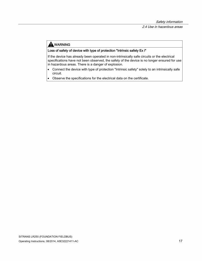
WARNING
Loss of safety of device with type of protection "Intrinsic safety Ex i"
If the device has already been operated in non-intrinsically safe circuits or the electrical specifications have not been observed, the safety of the device is no longer ensured for use in hazardous areas. There is a danger of explosion.
• Connect the device with type of protection "Intrinsic safety" solely to an intrinsically safe circuit.
• Observe the specifications for the electrical data on the certificate.

Safety information
2.4 Use in hazardous areas
SITRANS LR250 (FOUNDATION FIELDBUS)
18 Operating Instructions, 08/2014, A5E32221411-AC

SITRANS LR250 (FOUNDATION FIELDBUS)
Operating Instructions, 08/2014, A5E32221411-AC 19
Description 3 3.1 SITRANS LR250 overview
WARNING
Loss of protection
Danger to personnel, system and environment can result from improper use of the device.
• SITRANS LR250 is to be used only in the manner outlined in this manual, otherwise protection provided by the device may be impaired.
SITRANS LR250 is a 2-wire 25 GHz pulse radar level transmitter for continuous monitoring of liquids and slurries in storage vessels including high pressure and high temperature, to a range of 20 meters (66 feet). It is ideal for small vessels, material such as chemicals, food, beverages, solvents (including those of corrosive or aggressive nature), and low dielectric media.
The device consists of an electronic circuit coupled to an antenna and either a threaded or flange type process connection.
This device supports Foundation Fieldbus (FF) communication protocol. Signals are processed using Process Intelligence which has been field proven in over 1,000,000 applications worldwide (ultrasonic and radar). This device can be configured as an FF (H1) Link Master.

Description
3.2 Programming
SITRANS LR250 (FOUNDATION FIELDBUS)
20 Operating Instructions, 08/2014, A5E32221411-AC
3.2 Programming
This device is very easy to install and configure via a graphical local user interface (LUI). You can modify the built in parameters either locally via the Siemens infrared handheld programmer, or from a remote location using one of the following options:
● FF host system
● AMS Device Manager
3.3 Applications
● liquids and slurries
● bulk storage vessels
● simple process vessels
● corrosive and aggressive
● hygienic/sanitary
3.4 Approvals and certificates
Note
For further details see Approvals (Page 213).
SITRANS LR250 is available with approvals for General purpose, sanitary or hygienic and for hazardous areas. In all cases, check the nameplate on your device, and confirm the approval rating.
Process Connections A wide range of process connections and antenna options are available to suit virtually any vessel configuration.

SITRANS LR250 (FOUNDATION FIELDBUS)
Operating Instructions, 08/2014, A5E32221411-AC 21
Installing/mounting 4 4.1 Basic safety information
Note
Material compatibility
Siemens can provide you with support concerning selection of sensor components wetted by process media. However, you are responsible for the selection of components. Siemens accepts no liability for faults or failures resulting from incompatible materials.
WARNING
Unsuitable connecting parts
Danger of injury or poisoning.
In case of improper mounting hot, toxic and corrosive process media could be released at the connections.
• Ensure that connecting parts (such as flange gaskets and bolts) are suitable for connection and process media.
WARNING
Exceeded maximum ambient or process media temperature
Danger of explosion in hazardous areas.
Device damage.
• Make sure that the maximum permissible ambient and process media temperatures of the device are not exceeded.
WARNING
Open cable inlet or incorrect cable gland
Danger of explosion in hazardous areas.
• Close the cable inlets for the electrical connections. Only use cable glands or plugs which are approved for the relevant type of protection.

Installing/mounting
4.1 Basic safety information
SITRANS LR250 (FOUNDATION FIELDBUS)
22 Operating Instructions, 08/2014, A5E32221411-AC
WARNING
Incorrect conduit system
Danger of explosion in hazardous areas as result of open cable inlet or incorrect conduit system.
• In the case of a conduit system, mount a spark barrier at a defined distance from the device input. Observe national regulations and the requirements stated in the relevant approvals.
4.1.1 Pressure applications
DANGER
Pressure applications
Danger to personnel, system and environment will result from improper disassembly.
• Never attempt to loosen, remove, or disassemble process connection while vessel contents are under pressure.
WARNING
Pressure applications
Danger to personnel, system and environment can result from improper installation.
• Improper installation may result in loss of process pressure.
WARNING
Exceeded maximum permissible operating pressure
Danger of injury or poisoning.
The maximum permissible operating pressure depends on the device version. The device can be damaged if the operating pressure is exceeded. Hot, toxic and corrosive process media could be released.
• Make sure that the device is suitable for the maximum permissible operating pressure of your system.

Installing/mounting
4.1 Basic safety information
SITRANS LR250 (FOUNDATION FIELDBUS)
Operating Instructions, 08/2014, A5E32221411-AC 23
Note
• The process connection tag shall remain with the process pressure boundary assembly. (The process pressure boundary assembly comprises the components that act as a barrier against pressure loss from the process vessel: that is, the combination of process connection body and emitter, but normally excluding the electrical enclosure). In the event the device package is replaced, the process connection tag shall be transferred to the replacement unit.
• SITRANS LR250 units are hydrostatically tested, meeting or exceeding the requirement of the ASME Boiler and Pressure Vessel Code and the European Pressure Equipment Directive.
Note
• The serial numbers stamped in each process connection body, (flange, threaded, or sanitary), provide a unique identification number indicating date of manufacture. Example: MMDDYY – XXX (where MM = month, DD = day, YY = year, and XXX= sequential unit produced)
• Further markings (space permitting) indicate flange configuration, size, pressure class, material, and material heat code.
4.1.1.1 Pressure Equipment Directive, PED, 97/23/EC
Siemens Level Transmitters with flanged, threaded, or sanitary clamp type process mounts have no pressure-bearing housing of their own and, therefore, do not come under the Pressure Equipment Directive as pressure or safety accessories (see EU Commission Guideline 1/8 and 1/20).

Installing/mounting
4.2 Installation location requirements
SITRANS LR250 (FOUNDATION FIELDBUS)
24 Operating Instructions, 08/2014, A5E32221411-AC
4.2 Installation location requirements
WARNING
Aggressive atmospheres
Danger to personnel, system and environment can result from unsuitable environment.
• Provide an environment suitable to the housing rating and materials of construction.
CAUTION
Direct sunlight
Device damage.
The device can overheat or materials become brittle due to UV exposure.
• Protect the device from direct sunlight.
• Make sure that the maximum permissible ambient temperature is not exceeded. Refer to the information in Chapter "Technical data".

Installing/mounting
4.2 Installation location requirements
SITRANS LR250 (FOUNDATION FIELDBUS)
Operating Instructions, 08/2014, A5E32221411-AC 25
① Ambient temperature
② Device nameplate
③ Device tag
④ Process temperature (at process connection)
⑤ Process connection tag (contains process connection related information)
Antenna ① ③
Horn -40 to +80 °C (-40 to +176 °F)
with FKM O-ring:-40 to +200 °C (-40 to 392 °F)
with FFKM O-ring:-20 to +200 °C (-4 to +392 °F)
PVDF -40 to +80 °C (-40 to +176 °F)
-40 to +80 °C (-40 to +176 °F)
Flanged encapsulated -40 to +80 °C (-40 to +176 °F)
-40 to +170 °C (-40 to +338 °F)
Hygienic encapsulated -40 to +80 °C (-40 to +176 °F)
-40 to +170 °C (-40 to +338 °F)
with FKM seals used on process connection: -20 to +170 °C (-4 to +338 °F)
with EPDM seals used on process connection: -40 to +120 °C (-40 to +248 °F)
Note
Details about the process connection, process temperature and materials are laser etched into the body of the flanged and hygienic versions. All other SITRANS LR250 versions have details listed on a tag.

Installing/mounting
4.3 Proper mounting
SITRANS LR250 (FOUNDATION FIELDBUS)
26 Operating Instructions, 08/2014, A5E32221411-AC
4.3 Proper mounting
Note
• Correct location is key to a successful application.
• Avoid reflective interference from vessel walls and obstructions by following guidelines in this chapter.
NOTICE
Incorrect mounting
The device can be damaged, destroyed, or its functionality impaired through improper mounting.
• Before installing ensure there is no visible damage to the device.
• Make sure that process connectors are clean, and suitable gaskets and glands are used.
• Mount the device using suitable tools. Refer to the information in Installation instructions (Page 34) for installation torque requirements.
Note
• On devices with a removable head, there is no limit to the number of times a device can be rotated without damage.
• When mounting, orient the front or back of the device towards the closest vessel wall or obstruction.
• Do not rotate the enclosure after programming and vessel calibration, otherwise an error may occur, caused by a polarity shift of the transmit pulse.

Installing/mounting
4.3 Proper mounting
SITRANS LR250 (FOUNDATION FIELDBUS)
Operating Instructions, 08/2014, A5E32221411-AC 27
4.3.1 Nozzle design
Threaded PVDF antenna Stainless steel horn antenna
Flanged encapsulated antenna (FEA) Hygienic encapsulated antenna (HEA)
① Minimum clearance: 10 mm (0.4")
② Minimum diameter: 50 mm (2")
③ Maximum nozzle length
④ Maximum length/diameter ratio 1:1
● The end of the antenna must protrude a minimum of 10 mm (0.4") to avoid false echoes being reflected from the nozzle1).
● Minimum recommended nozzle diameter for the threaded PVDF antenna is 50 mm (2").
● An antenna extension (100 mm/3.93") is available for the horn antenna only.
● The maximum nozzle length for the FEA is 500 mm (19.68") when the nozzle diameter is DN150 (6"). Only shorter lengths are recommended for smaller diameters.
● When installing the SITRANS LR250 with hygienic process connection, it is good hygienic practice to install the antenna in a nozzle that has a maximum length/diameter ratio of 1:1. For example, 2" (DN50) diameter nozzle should be no longer than 2" (50 mm).
● When removing any sanitary/hygienic clamp version of the HEA to clean the lens, ensure it is re-installed in the exact position it was removed from, to avoid re-commissioning the device.
1) Not applicable for FEA or HEA

Installing/mounting
4.3 Proper mounting
SITRANS LR250 (FOUNDATION FIELDBUS)
28 Operating Instructions, 08/2014, A5E32221411-AC
4.3.2 Nozzle location
● Avoid central locations on tall, narrow vessels
● Nozzle must be vertical and clear of imperfections
Preferred
Undesirable
Beam angle
Note
• Beam width depends on antenna size and is approximate: see below.
• For details on avoiding false echoes, see Auto False Echo Suppression (Page 265).
● Beam angle is the width of the cone where the energy density is half of the peak energy density.
● The peak energy density is directly in front of and in line with the antenna.
● There is a signal transmitted outside the beam angle, therefore false targets may be detected.

Installing/mounting
4.3 Proper mounting
SITRANS LR250 (FOUNDATION FIELDBUS)
Operating Instructions, 08/2014, A5E32221411-AC 29
Horn antenna Flanged encapsulated antenna
Threaded PVDF antenna Hygienic encapsulated antenna
① Emission cone
② Beam angle

Installing/mounting
4.3 Proper mounting
SITRANS LR250 (FOUNDATION FIELDBUS)
30 Operating Instructions, 08/2014, A5E32221411-AC
Emission cone type and beam angle
Antenna type Antenna size Beam angle
Horn 1.5" 19°
2" 15°
3" 10°
4" 8°
Threaded PVDF 19°
Process connection size
Process connection type
Flanged encapsulated 2" Class 150 ASME B16.5 12.8°
3, 4, 6" Class 150 ASME B16.5 9.6°
50A 10K JIS B 2220 12.8°
80A/100A/150A 10K JIS B 2220 9.6°
DN50 PN10/16 EN1092-1 12.8°
DN80/DN100/DN150
PN10/16 EN1092-1 9.6°
Hygienic encapsulated 2" Sanitary Clamp according to ISO 2852
12.8°
3, 4" 9.6°
DN50 Aseptic/Hygienic nozzle/slotted nut according to DIN 11864-1 [Form A]
12.8°
DN80/DN100 9.6°
DN50 Aseptic/Hygienic flanged according to DIN 11864-2 [Form A]
12.8°
DN80/DN100 9.6°
DN50 Aseptic/Hygienic Clamp according to DIN 11864-3 [Form A]
12.8°
DN80/DN100 9.6°
DN50 Hygienic nozzle/slotted nut according to DIN 11851
12.8°
DN80/DN100 9.6°
Type F (50 mm) and Type N (68 mm)
Tuchenhagen Varivent 12.8°
Emission cone
● Keep emission cone free of interference from obstructions such as ladders, pipes, I-beams, or filling streams.
Access for programming
● Provide easy access for viewing the display and programming via the handheld programmer.

Installing/mounting
4.3 Proper mounting
SITRANS LR250 (FOUNDATION FIELDBUS)
Operating Instructions, 08/2014, A5E32221411-AC 31
4.3.3 Orientation in a vessel with obstructions
Polarization reference point
For best results on a vessel with obstructions, or a stillpipe with openings, orient the front or back of the device toward the obstructions. For an illustration, see Device orientation (Page 33).
① Polarization axis
② Polarization reference point
③ Display
Installing/mounting
4.3 Proper mounting
SITRANS LR250 (FOUNDATION FIELDBUS)
32 Operating Instructions, 08/2014, A5E32221411-AC
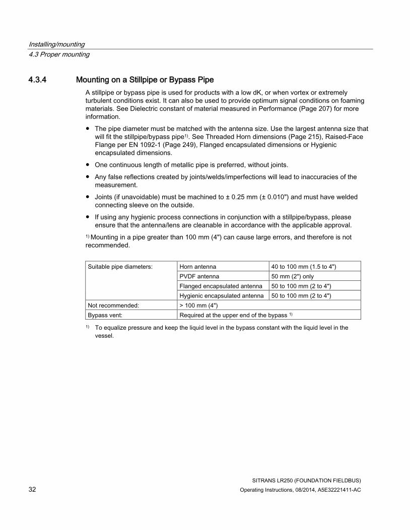
4.3.4 Mounting on a Stillpipe or Bypass Pipe
A stillpipe or bypass pipe is used for products with a low dK, or when vortex or extremely turbulent conditions exist. It can also be used to provide optimum signal conditions on foaming materials. See Dielectric constant of material measured in Performance (Page 207) for more information.
● The pipe diameter must be matched with the antenna size. Use the largest antenna size that will fit the stillpipe/bypass pipe1). See Threaded Horn dimensions (Page 215), Raised-Face Flange per EN 1092-1 (Page 249), Flanged encapsulated dimensions or Hygienic encapsulated dimensions.
● One continuous length of metallic pipe is preferred, without joints.
● Any false reflections created by joints/welds/imperfections will lead to inaccuracies of the measurement.
● Joints (if unavoidable) must be machined to ± 0.25 mm (± 0.010") and must have welded connecting sleeve on the outside.
● If using any hygienic process connections in conjunction with a stillpipe/bypass, please ensure that the antenna/lens are cleanable in accordance with the applicable approval.
1) Mounting in a pipe greater than 100 mm (4") can cause large errors, and therefore is not recommended.
Suitable pipe diameters: Horn antenna 40 to 100 mm (1.5 to 4")
PVDF antenna 50 mm (2") only
Flanged encapsulated antenna 50 to 100 mm (2 to 4")
Hygienic encapsulated antenna 50 to 100 mm (2 to 4")
Not recommended: > 100 mm (4")
Bypass vent: Required at the upper end of the bypass 1)
1) To equalize pressure and keep the liquid level in the bypass constant with the liquid level in the vessel.

Installing/mounting
4.3 Proper mounting
SITRANS LR250 (FOUNDATION FIELDBUS)
Operating Instructions, 08/2014, A5E32221411-AC 33
4.3.5 Device orientation
Bypass pipe installation Stillpipe installation
① Vent ① Align front or back of device with stillpipe slots1)
② Align front or back of device with vents1)
② Slots
1) Horn antenna version shown as example

Installing/mounting
4.4 Installation instructions
SITRANS LR250 (FOUNDATION FIELDBUS)
34 Operating Instructions, 08/2014, A5E32221411-AC
4.4 Installation instructions
WARNING
Pressure applications
Danger to personnel, system and environment can result from improper installation.
• Improper installation may result in loss of process pressure.
WARNING
Improper installation
Danger to personnel, system and environment can result from improper installation.
• Installation shall only be performed by qualified personnel and in accordance with local governing regulations.
NOTICE
Device handling
Damage to device may result from improper handling.
• Handle the device using the enclosure, not the process connection or tag, to avoid damage.
• Take special care when handling the threaded PVDF and Hygienic or Flanged encapsulated antennas. Any damage to the antenna surface, particularly to the tip/lens, could affect performance. (For example, do not sit device on its lens antenna.)
Note
• For European Union and member countries, installation must be according to ETSI EN 302372.
• Refer to the device nameplate for approval information.
Note
The outer part of the lens on the flanged encapsulated antenna version may not appear to lie flush before installation and this is normal. This will flatten after installation and will not impact the performance of the device.

Installing/mounting
4.4 Installation instructions
SITRANS LR250 (FOUNDATION FIELDBUS)
Operating Instructions, 08/2014, A5E32221411-AC 35
WARNING
Pressure applications
Danger of injury or poisoning.
It will be necessary to use PTFE tape or other appropriate thread sealing compound, and to tighten the process connection beyond hand-tight. (The maximum recommended torque for Threaded versions is 40 N-m (30 ft.lbs.) See Flanged versions (Page 37) for FEA recommended torque values.)
Note
• On devices with a removable head, there is no limit to the number of times a device can be rotated without damage.
• When mounting, orient the front or back of the device towards the closest vessel wall or obstruction.
• Do not rotate the enclosure after programming and vessel calibration, otherwise an error may occur, caused by a polarity shift of the transmit pulse.
Installing/mounting
4.4 Installation instructions
SITRANS LR250 (FOUNDATION FIELDBUS)
36 Operating Instructions, 08/2014, A5E32221411-AC
4.4.1 Threaded versions
WARNING
Pressure applications
Danger of injury or poisoning.
It may be necessary to use PTFE tape or other appropriate thread sealing compound, and to tighten the process connection beyond hand-tight. (The maximum recommended torque for Threaded versions is 40 N-m (30 ft.lbs.)
1. Before inserting the device into its mounting connection, check to ensure the threads are matching, to avoid damaging them.
2. Simply screw the device into the process connection, and hand tighten, or use a wrench.

Installing/mounting
4.4 Installation instructions
SITRANS LR250 (FOUNDATION FIELDBUS)
Operating Instructions, 08/2014, A5E32221411-AC 37
4.4.2 Flanged versions
NOTICE
Improper materials
The user is responsible for the selection of bolting and gasket materials (except for Flanged encapsulated antenna) which will fall within the limits of the process connection and its intended use, and which are suitable for the service conditions.
Special Instructions for Flanged encapsulated antenna only
Note
• Use spring washers
• Lens assembly acts as integral gasket, no other required
• Use recommended torque values for tightening bolts
Flange bolting: recommended torque
Pressure class Nominal pipe size (NPS)
Number of bolts Recommended torque (Nm)
ASME B16.5, Class 150
2" 4 30 – 50
3" 50 – 70
4" 8 40 – 60
6" 70 – 90
EN1092-1, PN16 /
JIS B 2220, 10K
DN50/50A 4 30 – 50
DN80/80A 8
DN100/100A
DN150/150A 60 – 80
Installing/mounting
4.4 Installation instructions
SITRANS LR250 (FOUNDATION FIELDBUS)
38 Operating Instructions, 08/2014, A5E32221411-AC
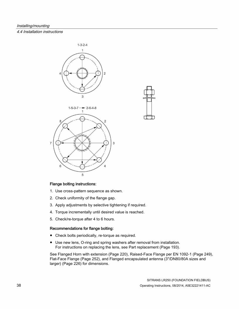
Flange bolting instructions:
1. Use cross-pattern sequence as shown.
2. Check uniformity of the flange gap.
3. Apply adjustments by selective tightening if required.
4. Torque incrementally until desired value is reached.
5. Check/re-torque after 4 to 6 hours.
Recommendations for flange bolting:
● Check bolts periodically, re-torque as required.
● Use new lens, O-ring and spring washers after removal from installation. For instructions on replacing the lens, see Part replacement (Page 193).
See Flanged Horn with extension (Page 220), Raised-Face Flange per EN 1092-1 (Page 249), Flat-Face Flange (Page 252), and Flanged encapsulated antenna (3"/DN80/80A sizes and larger) (Page 226) for dimensions.

Installing/mounting
4.4 Installation instructions
SITRANS LR250 (FOUNDATION FIELDBUS)
Operating Instructions, 08/2014, A5E32221411-AC 39
4.4.3 Hygienic versions
WARNING
Loss of sanitary approvals
Loss of sanitary approvals can result from improper installation/mounting.
• Take special care when installing in hygienic or sanitary applications. Comply with installation/mounting guidelines to ensure cleanliness and the ability to keep the wetted parts in a position to be readily cleanable. (See relevant EHEDG/3A documentation - not supplied).
NOTICE
Loss of sanitary approvals
• For 3-A Sanitary Approved device installation where the customer tank process connection exists, a leak detection port of minimum 2.4 mm diameter must be provided at the lowest point in the process connection where leakage can occur.
• If leakage is detected at any time while the device is installed, then the device process connection parts must be disassembled and thoroughly cleaned prior to gasket replacement and reassembly.
Note
• For Hygienic encapsulated antenna, the lens acts as a gasket/seal and should be used in conjunction with a cleanable seal as required by the specific process connections (for example, DIN 11864-3).
Hygienic encapsulated antenna leak detection port
① Orientation mark for leak detection port
② Leak detection port

Installing/mounting
4.5 Disassembly
SITRANS LR250 (FOUNDATION FIELDBUS)
40 Operating Instructions, 08/2014, A5E32221411-AC
4.5 Disassembly
DANGER
Pressure applications
Danger to personnel, system and environment will result from improper disassembly.
• Never attempt to loosen, remove, or disassemble process connection while vessel contents are under pressure.
WARNING
Incorrect disassembly
The following dangers may result through incorrect disassembly:
- Injury through electric shock
- Danger through emerging media when connected to the process
- Danger of explosion in hazardous area
In order to disassemble correctly, observe the following:
• Before starting work, make sure that you have switched off all physical variables such as pressure, temperature, electricity etc. or that they have a harmless value.
• If the device contains dangerous media, it must be emptied prior to disassembly. Make sure that no environmentally hazardous media are released.
• Secure the remaining connections so that no damage can result if the process is started unintentionally.

SITRANS LR250 (FOUNDATION FIELDBUS)
Operating Instructions, 08/2014, A5E32221411-AC 41
Connecting 5 5.1 Basic safety information
NOTICE
Condensation in the device
Damage to device through formation of condensation if the temperature difference between transportation or storage and the mounting location exceeds 20 °C (68°F).
• Before taking the device into operation let the device adapt for several hours in the new environment.
WARNING
Missing PE/ground connection
Danger of electric shock.
Depending on the device version, connect the power supply as follows:
• Power plug: Ensure that the used socket has a PE/ground conductor connection. Check that the PE/ground conductor connection of the socket and power plug match each other.
• Connecting terminals: Connect the terminals according to the terminal connection diagram. First connect the PE/ground conductor.
5.2 Connecting SITRANS LR250
WARNING
Incorrect connection to power source
Danger to personnel, system and environment can result from improper power connection.
• The DC input terminals shall be supplied from a source providing electrical isolation between the input and output, in order to meet the applicable safety requirements of IEC 61010-1.
• All field wiring must have insulation suitable for rated voltages.

Connecting
5.2 Connecting SITRANS LR250
SITRANS LR250 (FOUNDATION FIELDBUS)
42 Operating Instructions, 08/2014, A5E32221411-AC
WARNING
Loss of protection
Loss of approvals can result from improper installation.
• Check the nameplate on your device, to verify the approval rating.
• Use appropriate conduit seals to maintain IP or NEMA rating.
• See Wiring setups for hazardous area installation (Page 45).
NOTICE
Improper cables and conduit
• Separate cables and conduits may be required to conform to standard instrumentation wiring practices or electrical codes.
① Use a 2 mm Allen key to loosen the lid-lock set screw c) ④ Cable shield
② Plug (IP68) ⑤ Ground terminal
③ Optional cable glanda) b)(or NPT cable entry)b)
a) May be shipped with the device. b) If cable is routed through conduit, use only approved suitable-size hubs for waterproof applications. c) Not applicable to 3-A Sanitary approved device.

Connecting
5.2 Connecting SITRANS LR250
SITRANS LR250 (FOUNDATION FIELDBUS)
Operating Instructions, 08/2014, A5E32221411-AC 43
Wiring instructions
1. Strip the cable jacket for approximately 70 mm (2.75") from the end of the cable, and thread the wires through the gland. (If cable is routed through conduit, use only approved suitable-size hubs for waterproof applications.)
2. Connect the wires to the terminals as shown: SITRANS LR250 (FF) is not polarity sensitive.
3. Ground the device according to local regulations.
4. Tighten the gland to form a good seal.
5. Close the lid and secure the locking screw before programming and device configuration.
Note
Lid-lock set screw not applicable to 3-A Sanitary approved device.
Note
• Foundation Fieldbus (H1) must be terminated at both extreme ends of the cable for it to work properly.
• For optimum EMC protection, it is recommended that the FF H1 cable shield be connected to ground at every node.
• Please refer to the Foundation Fieldbus System Engineering Guidelines (AG-181) Revision 2.0, for information on installing FF (H1) devices available from: Foundation Fieldbus (http://www.fieldbus.org/)
• If a Weidmüller or other current limiting junction box is connected to this device, please ensure that the current limit is set to 40 mA or higher.
Connecting
5.2 Connecting SITRANS LR250
SITRANS LR250 (FOUNDATION FIELDBUS)
44 Operating Instructions, 08/2014, A5E32221411-AC
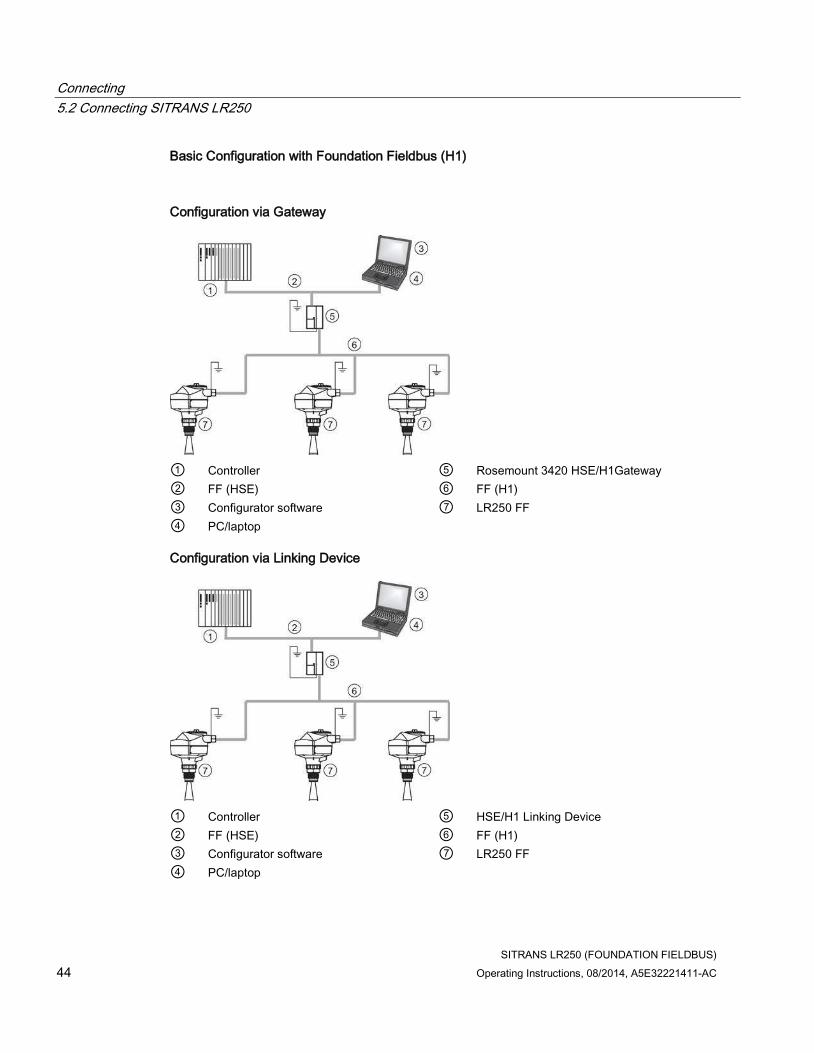
Basic Configuration with Foundation Fieldbus (H1)
Configuration via Gateway
① Controller ⑤ Rosemount 3420 HSE/H1Gateway
② FF (HSE) ⑥ FF (H1)
③ Configurator software ⑦ LR250 FF
④ PC/laptop
Configuration via Linking Device
① Controller ⑤ HSE/H1 Linking Device
② FF (HSE) ⑥ FF (H1)
③ Configurator software ⑦ LR250 FF
④ PC/laptop

Connecting
5.3 Wiring setups for hazardous area installation
SITRANS LR250 (FOUNDATION FIELDBUS)
Operating Instructions, 08/2014, A5E32221411-AC 45
Configuration via PCI/PCMCIA Card
① Configurator software ④ H1 Interface
② PC/laptop ⑤ FF (H1)
③ PCI/PCMCIA bus ⑥ LR250 FF
5.3 Wiring setups for hazardous area installation
There are three wiring options for hazardous area installations:
● Intrinsically safe wiring (Page 47)
● Non-sparking wiring (Page 50)
● Non-incendive wiring (US/Canada only) (Page 50)
In all cases, check the nameplate on your instrument, confirm the approval rating, and perform installation and wiring according to your local safety codes.

Connecting
5.3 Wiring setups for hazardous area installation
SITRANS LR250 (FOUNDATION FIELDBUS)
46 Operating Instructions, 08/2014, A5E32221411-AC
5.3.1 Configuration with Foundation Fieldbus for hazardous areas
Configuration via Gateway
① Controller ⑤ Ex ia type HSE/H1
② FF (HSE) ⑥ FF (H1)
③ Configurator software ⑦ LR250 FF
④ PC/laptop
Configuration via Linking Device
① Controller ⑤ Ex ia type HSE/H1 Linking Device
② FF (HSE) ⑥ FF (H1)
③ Configurator software ⑦ LR250 (FF)
④ PC/laptop

Connecting
5.3 Wiring setups for hazardous area installation
SITRANS LR250 (FOUNDATION FIELDBUS)
Operating Instructions, 08/2014, A5E32221411-AC 47
Configuration via PCI/PCMCIA Card
① PCI/PCMCIA bus ④ Ex ia type H1 Interface
② Configurator software ⑤ FF (H1)
③ PC/laptop ⑥ LR250 FF
5.3.2 Intrinsically safe wiring
Device nameplate (ATEX/IECEx/RCM)
① ATEX certificate
The ATEX certificates listed on the nameplate can be downloaded from our website:
Product page (http://www.siemens.com/LR250)
Go to Support > Approvals / Certificates.
The IECEx certificate listed on the nameplate can be viewed on the IECEx website. Go to:
IECEx (http://iecex.iec.ch/)
Click on Certified Equipment and enter the certificate number IECEx SIR 09.0148X.

Connecting
5.3 Wiring setups for hazardous area installation
SITRANS LR250 (FOUNDATION FIELDBUS)
48 Operating Instructions, 08/2014, A5E32221411-AC
5.3.2.1 Intrinsically safe wiring (FM/CSA)
Device nameplate (FM/CSA)
① Connection drawing number
The FM/CSA Intrinsically Safe connection drawing number A5E02358161 can be downloaded from our website at:
Product page (http://www.siemens.com/LR250)
Go to Support > Installation Drawings > Level Measurement > SITRANS LR250.
● For wiring requirements: follow local regulations.
● Approved dust-tight and water-tight conduit seals are required for outdoor NEMA 4X / type 4X / NEMA 6, IP67, IP68 locations.
● Refer to Instructions specific to hazardous area installations (Page 51).
Entity concept:
The Entity Concept allows interconnection of intrinsically safe apparatus to associated apparatus not specifically examined in such combination. The criteria for interconnection is that the voltage and current which intrinsically safe apparatus can receive and remain intrinsically safe, considering faults, must be equal to or greater than the output voltage (Uo) and output current (Io) levels which can be delivered by the associated apparatus, considering faults and applicable factors. In addition, the maximum unprotected capacitance (Ci) and Inductance (Li) of the intrinsically safe apparatus, including interconnecting wiring, must be equal to or less than the capacitance and inductance which can be safely connected to associated apparatus.
Under the entity evaluation concept, SITRANS LR250 has the following characteristics:
(input voltage) Ui = 24 V
(input current) Ii = 250 mA
(input power) Pi = 1.2 W
(internal capacitance) Ci = 0
(internal inductance) Li = 0

Connecting
5.3 Wiring setups for hazardous area installation
SITRANS LR250 (FOUNDATION FIELDBUS)
Operating Instructions, 08/2014, A5E32221411-AC 49
FISCO Concept
Note
For complete details and instructions regarding the FISCO Concept The FM/CSA connection drawing number A5E02358161 can be downloaded from our website at: Product page (http://www.siemens.com/LR250) Go to Support > Installation Drawings > Level Measurement > SITRANS LR250.
The FISCO Concept allows interconnection of intrinsically safe apparatus to associated apparatus not specifically examined in such combination. The criteria for interconnection is that the voltage (Ui or Vmax), the current (Ii, or Imax) and the power (Pi, or Pmax) which intrinsically safe apparatus can receive and remain intrinsically safe, considering faults, must be equal to or greater than the voltage (Uo or Voc or Vi), the current (lo or Isc or li), and the power (Po or Pmax) levels which can be delivered by the associated apparatus, considering faults and applicable factors. In addition, the maximum unprotected capacitance (Ci) and inductance (Li) of each apparatus (other than the termination) connected to the fieldbus must be less than or equal to 5 nF and 10 μH respectively.
In each segment only one active device, normally the associated apparatus, is allowed to provide the necessary energy for the fieldbus system. The allowed voltage Uo (or Voc or Vt) of the associated apparatus is limited to the range of 14V dc to 24V dc. All other equipment connected to the bus cable has to be passive, meaning that they are not allowed to provide energy to the system, except for a leakage current of 50 μA for each connected device. Separately powered equipment needs a galvanic isolation to assure that the Intrinsically Safe fieldbus circuit remains passive.
Under the FISCO evaluation concept, SITRANS LR250 has the following characteristics:
(input voltage) Ui = 17.5 V
(input current) Ii = 380 mA
(input power) Pi = 5.32 W
(internal capacitance) Ci = 0
(internal inductance) Li = 0

Connecting
5.3 Wiring setups for hazardous area installation
SITRANS LR250 (FOUNDATION FIELDBUS)
50 Operating Instructions, 08/2014, A5E32221411-AC
5.3.3 Non-sparking wiring
① ATEX certificate
The ATEX certificate listed on the nameplate can be downloaded from our website:
Product page (http://www.siemens.com/LR250)
Go to: Support > Installation drawings > Level measurement > SITRANS LR250.
● For wiring requirements follow local regulations.
● Approved dust-tight and water-tight conduit seals are required for outdoor NEMA 4X / type 4X / NEMA 6, IP67, IP68 locations.
5.3.4 Non-incendive wiring (US/Canada only)
FM/CSA Class 1, Div 2 connection drawing number 23650673 can be downloaded from our website:
Product page (http://www.siemens.com/LR250)
Go to Support > Installation Drawings > Level Measurement > SITRAINS LR250.
● For wiring requirements: follow local regulations.
● Approved dust-tight and water-tight conduit seals are required for outdoor NEMA 4X / type 4X / NEMA 6, IP67, IP68 locations.
● Refer to Instructions specific to hazardous area installations (Page 51).

Connecting
5.4 Instructions specific to hazardous area installations
SITRANS LR250 (FOUNDATION FIELDBUS)
Operating Instructions, 08/2014, A5E32221411-AC 51
5.4 Instructions specific to hazardous area installations
5.4.1 (Reference European ATEX Directive 94/9/EC, Annex II, 1/0/6)
The following instructions apply to equipment covered by certificate number SIRA 06ATEX2353X and 09ATEX4354X:
1. For use and assembly, refer to the main instructions.
2. The equipment is certified for use as Category 1GD equipment per SIRA 06ATEX2353X, and Category 3G equipment per SIRA 09ATEX4354X.
3. The equipment may be used with flammable gases and vapors with apparatus group IIC, IIB and IIA and temperature classes T1, T2, T3 and T4.
4. The equipment has a degree of ingress protection of IP67 and a temperature class of T100 oC and may be used with flammable dusts.
5. The equipment is certified for use in an ambient temperature range of –40 oC to +80 oC.
6. The equipment has not been assessed as a safety related device (as referred to by Directive 94/9/EC Annex II, clause 1.5).
7. Installation and inspection of this equipment shall be carried out by suitably trained personnel in accordance with the applicable code of practice (EN 60079-14 and EN 60079-17 in Europe).
8. The equipment is non-repairable.
9. The certificate numbers have an ’X’ suffix, which indicates that special conditions for safe use apply. Those installing or inspecting this equipment must have access to the certificates.
10.If the equipment is likely to come into contact with aggressive substances, then it is the responsibility of the user to take suitable precautions that prevent it from being adversely affected, thus ensuring that the type of protection is not compromised.
– Aggressive substances: e.g. acidic liquids or gases that may attack metals, or solvents that may affect polymeric materials.
– Suitable precautions: e.g. establishing from the material’s data sheet that it is resistant to specific chemicals.
Connecting
5.4 Instructions specific to hazardous area installations
SITRANS LR250 (FOUNDATION FIELDBUS)
52 Operating Instructions, 08/2014, A5E32221411-AC
Special conditions for safe use (denoted by X after the certificate number)
● Parts of the enclosure may be non-conducting and may generate an ignition-capable level of electrostatic charge under certain extreme conditions. The user should ensure that the equipment is not installed in a location where it may be subjected to external conditions (such as high-pressure steam), which might cause a build-up of electrostatic charge on non-conducting surfaces.
● Aluminium, magnesium, titanium or zirconium may be used at the accessible surface of the equipment. In the event of rare incidents, ignition sources due to impact and friction sparks could occur. This shall be considered when the SITRANS LR250 FF is being installed in locations that specifically require Equipment Protection level Ga or Da.
● The equipment shall be infallibly bonded according to the relevant code of practice.
● The end use must ensure that the explosion protection and ingress protection of IP64 is maintained at each entry to the enclosure by use of a blanking element or cable entry device that meets the requirements of the protection concepts type 'n' or increased safety 'e' or flameproof 'd'.

SITRANS LR250 (FOUNDATION FIELDBUS)
Operating Instructions, 08/2014, A5E32221411-AC 53
Commissioning 6 6.1 Basic safety information
WARNING
Loss of explosion protection
Danger of explosion when device is not properly commissioned
If opening device
• Isolate from power.
- or -
• Ensure that the atmosphere is explosion-free (hot work permit).
Ensure device is properly closed before returning to operation.
6.2 Operating via the handheld programmer
The handheld programmer used with this device contains lithium batteries that are non-replaceable.
Lithium batteries are primary power sources with high energy content designed to provide the highest possible degree of safety.
WARNING
Potential hazard
Lithium batteries may present a potential hazard if they are abused electrically or mechanically. Observe the following precautions when handling and using lithium batteries:
• Do not short-circuit, recharge or connect with false polarity.
• Do not expose to temperatures beyond the specified temperature range.
• Do not incinerate.
• Do not crush, puncture or open cells or disassemble.
• Do not weld or solder to the battery’s body.
• Do not expose contents to water.

Commissioning
6.2 Operating via the handheld programmer
SITRANS LR250 (FOUNDATION FIELDBUS)
54 Operating Instructions, 08/2014, A5E32221411-AC
6.2.1 Power up
Power up the device. A transition screen showing first the Siemens logo and then the current firmware revision is displayed while the first measurement is being processed. SITRANS LR250 automatically starts up in Measurement mode. The first time the device is configured, you will be prompted to select a language (English, German, French, Spanish or Chinese).To change the language again, see Language (7.).
Press Mode to toggle between Measurement and Program mode.
[If the SITRANS LR250 FF is to be used in an FF application, configure using a network configuration tool, such as DeltaV or NI-FBUS Configurator. See Quick Start Wizard via AMS Device Manager (Page 81).]
Follow these steps to configure the device via the LUI:
● Complete the Quick Start Wizard [see Quick Start Wizard via the handheld programmer (Page 63)]. Completing the Quick Start Wizard or writing any parameter via the LUI causes the device to begin measuring. The Resource Block (RES) and Level Transducer Block (LTB) will move to Automatic mode.
● AIFB 1 and AIFB 2 will remain Out of Service (as displayed on the LCD). These blocks can only be configured and scheduled using a network configuration tool. For more details, see System Integration in manual Foundation Fieldbus for Level Instruments (7ML19985MP01).
Note
The last step of the Quick Start run from the LUI will place the RESOURCE block in Automatic mode.
6.2.2 Handheld programmer functions
The radar device carries out its level measurement tasks according to settings made via parameters. The settings can be modified locally via the Local User Interface (LUI) which consists of an LCD display and a handheld programmer.
A Quick Start Wizard provides an easy step-by-step procedure to configure the device for a simple application. Access the wizards:
● locally [see Quick Start Wizard via the handheld programmer (Page 63)]
● or from a remote location [see Quick Start Wizard via AMS Device Manager (Page 81)]
For more complex setups see Application Examples (Page 68), and for the complete range of parameters see Parameter Reference (Page 139).

Commissioning
6.2 Operating via the handheld programmer
SITRANS LR250 (FOUNDATION FIELDBUS)
Operating Instructions, 08/2014, A5E32221411-AC 55
6.2.2.1 The LCD display
Measurement mode display
Normal operation
① toggle indicator a) for analog input function blocks (AIFB 1/AIFB 2, displayed as FB1/FB2)
② identifies which block is source of displayed value
③ Measured value (level, space, distance, or volume)
④ Units
⑤ Bar graph indicates level
⑥ Secondary region indicates on request b) electronics temperature, echo confidence, loop current, or distance
⑦ Text area displays status messages
⑧ Device status indicator, see Device status icons (Page 198) a) Press UP or DOWN arrow to switch. b) In response to a key press request. For details, see Handheld programmer (Part No. 7ML1930-1BK) (Page 57) for key functions in Measurement mode.
Fault present
① service required icon appears
② Device status indicator, see Device status icons (Page 198)
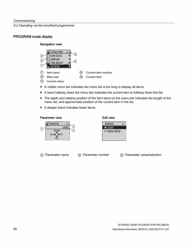
Commissioning
6.2 Operating via the handheld programmer
SITRANS LR250 (FOUNDATION FIELDBUS)
56 Operating Instructions, 08/2014, A5E32221411-AC
PROGRAM mode display
Navigation view
① Item band ④ Current item number
② Menu bar ⑤ Current item
③ Current menu
● A visible menu bar indicates the menu list is too long to display all items.
● A band halfway down the menu bar indicates the current item is halfway down the list.
● The depth and relative position of the item band on the menu bar indicates the length of the menu list, and approximate position of the current item in the list.
● A deeper band indicates fewer items.
Parameter view Edit view
① Parameter name ② Parameter number ③ Parameter value/selection
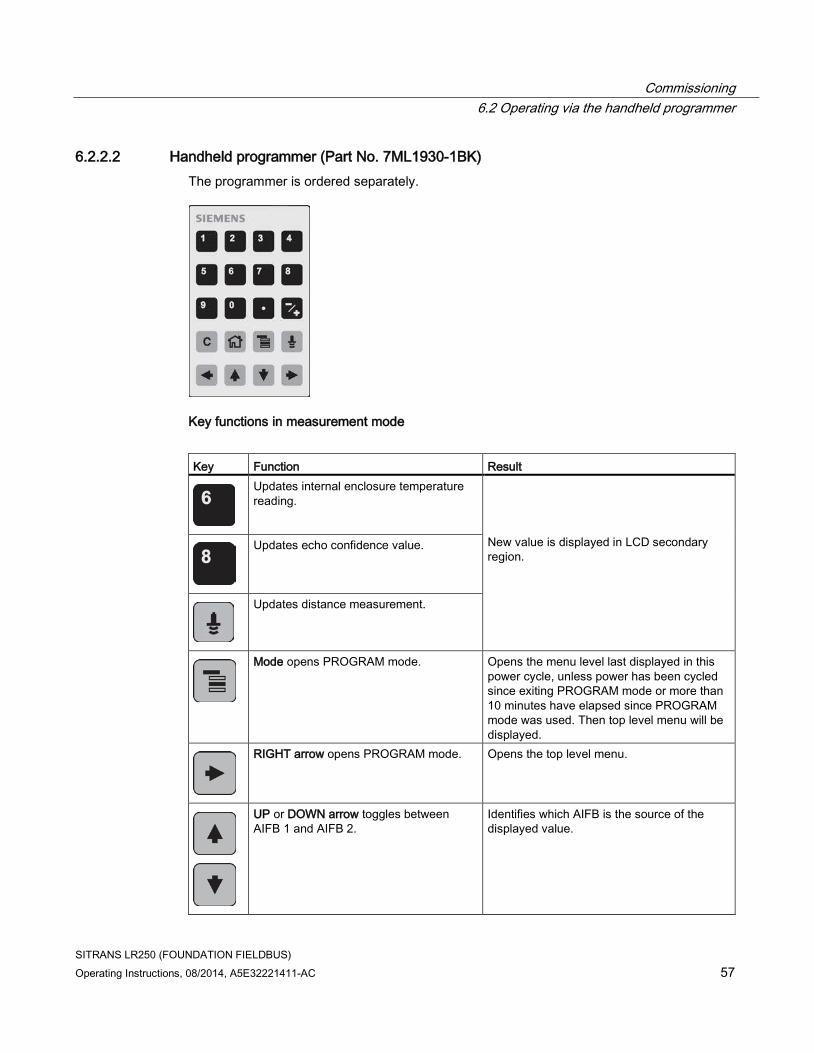
Commissioning
6.2 Operating via the handheld programmer
SITRANS LR250 (FOUNDATION FIELDBUS)
Operating Instructions, 08/2014, A5E32221411-AC 57
6.2.2.2 Handheld programmer (Part No. 7ML1930-1BK)
The programmer is ordered separately.
Key functions in measurement mode
Key Function Result
Updates internal enclosure temperature reading.
New value is displayed in LCD secondary region.
Updates echo confidence value.
Updates distance measurement.
Mode opens PROGRAM mode. Opens the menu level last displayed in this power cycle, unless power has been cycled since exiting PROGRAM mode or more than 10 minutes have elapsed since PROGRAM mode was used. Then top level menu will be displayed.
RIGHT arrow opens PROGRAM mode. Opens the top level menu.
UP or DOWN arrow toggles between AIFB 1 and AIFB 2.
Identifies which AIFB is the source of the displayed value.

Commissioning
6.2 Operating via the handheld programmer
SITRANS LR250 (FOUNDATION FIELDBUS)
58 Operating Instructions, 08/2014, A5E32221411-AC
6.2.3 Programming
Note
• While the device is in PROGRAM mode the output remains active and continues to respond to changes in the device.
• The device automatically returns to Measurement mode after a period of inactivity in PROGRAM mode (between 15 seconds and 10 minutes, depending on the menu level).
Change parameter settings and set operating conditions to suit your specific application. For remote operation see Operating via AMS Device Manager (Page 75).
Parameter menus
Note
For the complete list of parameters with instructions, see Parameter reference (Page 139).
Parameters are identified by name and organized into function groups. See LCD menu structure (Page 289).
1. QUICK START
2. SETUP
2.1. IDENTIFICATION 2.2. DEVICE ............
2.4. LINEARIZATION
2.4.1. VOLUME
2.4.1.1. VESSEL SHAPE

Commissioning
6.2 Operating via the handheld programmer
SITRANS LR250 (FOUNDATION FIELDBUS)
Operating Instructions, 08/2014, A5E32221411-AC 59
1. Enter PROGRAM mode
● Point the programmer at the display from a maximum distance of 300 mm (1 ft).
● RIGHT arrow activates PROGRAM mode and opens menu level 1.
● Mode opens the menu level last displayed in PROGRAM mode within the last 10 minutes,
or menu level 1 if power has been cycled since then.
① Handheld programmer ② Display ③ Maximum distance: 300 mm ( 1 ft)
2. Navigating: key functions in Navigation mode
Note
• In Navigation mode ARROW keys move to the next menu item in the direction of the arrow.
• For Quick Access to parameters via the handheld programmer, press Home , then
enter the menu number, for example: Volume (2.4.1.), press 2.4.1.

Commissioning
6.2 Operating via the handheld programmer
SITRANS LR250 (FOUNDATION FIELDBUS)
60 Operating Instructions, 08/2014, A5E32221411-AC
Key Name Menu level Function
UP or DOWN arrow
menu or parameter
Scroll to previous or next menu or parameter
RIGHT arrow menu Go to first parameter in the selected menu, or open next menu.
parameter Open Edit mode.
LEFT arrow menu or parameter
Open parent menu.
Mode menu or parameter
Change to MEASUREMENT mode.
Home menu or parameter
Open top level menu: menu 1.
3. Editing in PROGRAM mode
● Navigate to the desired parameter.
● Press RIGHT arrow to open parameter view.
● Press RIGHT arrow again to open Edit mode. The current selection is highlighted. Scroll
to a new selection.
● Press RIGHT arrow to accept it. The LCD returns to parameter view and displays the new
selection.
① Parameter name ② Parameter number ③ Current selection

Commissioning
6.2 Operating via the handheld programmer
SITRANS LR250 (FOUNDATION FIELDBUS)
Operating Instructions, 08/2014, A5E32221411-AC 61
4. Changing a numeric value
● Navigate to the desired parameter.
● Press RIGHT arrow to open parameter view. The current value is displayed.
● Press RIGHT arrow again to open Edit mode. The current value is highlighted.
● Key in a new value.
● Press RIGHT arrow to accept it. Press RIGHT arrow to accept it. The LCD returns to
parameter view and displays the new selection.
① Parameter name ② Parameter number ③ Current selection

Commissioning
6.2 Operating via the handheld programmer
SITRANS LR250 (FOUNDATION FIELDBUS)
62 Operating Instructions, 08/2014, A5E32221411-AC
Key functions in edit mode
Key Name Function
UP or DOWN arrow
Selecting options
Scrolls to item.
Numeric editing
• Increments or decrements digits
• Toggles plus and minus sign
RIGHT arrow Selecting options
• Accepts the data (writes the parameter)
• Changes from Edit to Navigation mode
Numeric editing
• Moves cursor one space to the right
• or, with cursor on Enter sign, accepts the data and changes from Edit to Navigation mode
LEFT arrow: Selecting options
Cancels Edit mode without changing the parameter.
Numeric editing
• Moves cursor to plus/minus sign if this is the first key pressed
• or moves cursor one space to the left
• or with cursor on the Enter sign, cancels the entry.
Clear Numeric editing
Erases the display.
Decimal point Numeric editing
• Enters a decimal point
• Captures the current path [see Secondary Value (4.11.)]
Plus or minus sign
Numeric editing
Changes the sign of the entered value.
to
Numeral Numeric editing
Enters the corresponding character.

Commissioning
6.2 Operating via the handheld programmer
SITRANS LR250 (FOUNDATION FIELDBUS)
Operating Instructions, 08/2014, A5E32221411-AC 63
6.2.3.1 Quick Start Wizard via the handheld programmer_note
Note
• A reset to factory defaults should be performed before running the Quick Start Wizard if the device has been used in a previous application. See Master Reset (4.1.).
• The Quick Start wizard settings are inter-related and changes apply only after you select Finish in the Wizard Complete step.
• Do not use the Quick Start wizard to modify parameters: see instead Parameter reference (Page 139). (Perform customization for your application only after the Quick Start has been completed).
• Default settings in the parameter tables are indicated with an asterisk (*).
1. Quick Start
1.1. Quick Start Wiz
● Point the programmer at the display from a maximum distance of 300 mm (1 ft), then press
RIGHT arrow to activate PROGRAM mode and open menu level 1.
● Press RIGHT arrow twice to navigate to menu item 1.1 and open parameter view.
● Press RIGHT arrow to open Edit mode or DOWN arrow to accept default values and
move directly to the next item.
● To change a setting, scroll to the desired item or key in a new value.
● After modifying a value, press RIGHT arrow to accept it and press DOWN arrow to
move to the next item.
● Quick Start settings take effect only after you select Finish.

Commissioning
6.2 Operating via the handheld programmer
SITRANS LR250 (FOUNDATION FIELDBUS)
64 Operating Instructions, 08/2014, A5E32221411-AC
Material
Selects the appropriate echo processing algorithms for the material [see Position Detect (2.5.7.2.) for more detail].
Options * LIQUID
LIQUID LOW DK a) (low dielectric liquid – CLEF algorithm enabled)
a) dK < 3.0
Response rate
Sets the reaction speed of the device to measurement changes in the target range. Use a setting just faster than the maximum filling or emptying rate (whichever is greater).
Options Response rate (2.3.8.1.)
Fill rate per Minute (2.3.8.2.)/ Empty rate per Minute (2.3.8.3.)
* SLOW 0.1 m/min (0.32 ft/min)
MED 1.0 m/min (3.28 ft/min)
FAST 10.0 m/min (32.8 ft/min)
Units
Sensor measurement units.
Options m, cm, mm, ft, in
Default: m

Commissioning
6.2 Operating via the handheld programmer
SITRANS LR250 (FOUNDATION FIELDBUS)
Operating Instructions, 08/2014, A5E32221411-AC 65
Operation
Operation Description
NO SERVICE Measurement and associated loop current are not updated, and the device defaults to Fail-safe mode a).
LEVEL * Distance to material surface referenced from Low calibration point
SPACE Distance to material surface referenced from High calibration point
DISTANCE Distance to material surface referenced from Sensor reference point
a) See Material Level (2.3.5.) for more detail.
① Space ④ High calibration point (process full level)
② Level ⑤ Sensor reference point a)
③ Distance ⑥ Low calibration point (process empty level)
a) The point from which High and Low Calibration points are referenced: see Dimension Drawings.
Low calibration point
Distance from Sensor Reference to Low Calibration Point: usually process empty level. (See Operation for an illustration.)
Values Range: 0.00 to 20.00 m
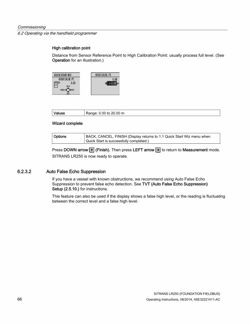
Commissioning
6.2 Operating via the handheld programmer
SITRANS LR250 (FOUNDATION FIELDBUS)
66 Operating Instructions, 08/2014, A5E32221411-AC
High calibration point
Distance from Sensor Reference Point to High Calibration Point: usually process full level. (See Operation for an illustration.)
Values Range: 0.00 to 20.00 m
Wizard complete
Options BACK, CANCEL, FINISH (Display returns to 1.1 Quick Start Wiz menu when Quick Start is successfully completed.)
Press DOWN arrow (Finish). Then press LEFT arrow to return to Measurement mode.
SITRANS LR250 is now ready to operate.
6.2.3.2 Auto False Echo Suppression
If you have a vessel with known obstructions, we recommend using Auto False Echo Suppression to prevent false echo detection. See TVT (Auto False Echo Suppression) Setup (2.5.10.) for instructions.
This feature can also be used if the display shows a false high level, or the reading is fluctuating between the correct level and a false high level.

Commissioning
6.2 Operating via the handheld programmer
SITRANS LR250 (FOUNDATION FIELDBUS)
Operating Instructions, 08/2014, A5E32221411-AC 67
6.2.3.3 Requesting an Echo Profile
• In PROGRAM mode, navigate to: Level Meter > Diagnostics (3.) > Echo Profile (3.1.)
• Press RIGHT arrow to request a profile.
① Confidence ⑦ Zoom
② Distance from Low Calibration Point to vertical cross-hair ⑧ Measure
③ Algorithm: tF (trueFirst) ⑨ Exit
④ Distance from flange face to target ⑩ Exit icon selected
⑤ Pan left/right - selected ⑪ Exit icon deselected
⑥ Pan up/down
● Use UP or DOWN arrow to scroll to an icon. When an icon is highlighted, that feature
becomes active.
● To move a cross-hair, press RIGHT arrow to increase the value, LEFT arrow to
decrease.
● To Zoom into an area, position the intersection of the cross-hairs at the center of that area,
select Zoom, and press RIGHT arrow. Press LEFT arrow to Zoom out.
● To update the profile, select Measure and press RIGHT arrow.
● To return to the previous menu, select Exit then press RIGHT arrow.
Commissioning
6.3 Application examples
SITRANS LR250 (FOUNDATION FIELDBUS)
68 Operating Instructions, 08/2014, A5E32221411-AC
6.2.3.4 Device Address
Note
The address can only be changed from a remote master such as NI-FBUS Configurator or DeltaV. See Addressing in manual Foundation Fieldbus for Level Instruments (7ML19985MP01) for further details.
Read only. The unique address of the device on the network.
Values Temporary range during initial commissioning: 248 - 251. Permanent range after commissioning complete (written to non-volatile memory in the device): 16-247
● In PROGRAM mode, navigate to: Level Meter > Communication (5.) > Device Address (5.2.) to view the device address.
● Press Mode to return to Measurement mode.
6.3 Application examples
Note
In the applications illustrated below, values are for example purposes only.
You can use these examples as setup references. Enter the values in the parameter tables to select the corresponding functions.
Configure the basic settings using the Quick Start wizard parameters. (These parameters are inter-related, and changes take effect only after you select FINISH in final step: Wizard Complete.)
In each example, after performing a Quick Start, navigate to the other required parameters (either via the handheld programmer or via AMS Device Manager) and enter the appropriate values.

Commissioning
6.3 Application examples
SITRANS LR250 (FOUNDATION FIELDBUS)
Operating Instructions, 08/2014, A5E32221411-AC 69
6.3.1 Liquid resin in storage vessel, level measurement
Note
Minimum distance from flange face to target is limited by Near Range (2.5.1.).
To obtain level measurement/4 to 20 mA output proportional to resin levels:
● Low Calibration Pt. = 5 m (16.5 ft) from sensor reference point
● High Calibration Pt.= 0.5 m (1.64 ft) from sensor reference point
● Max.fill/empty rate = 0.2 m/min (0.65 ft/min)
In the event of a loss of echo:
● SITRANS LR250 is to go into Fail-safe High after 2 minutes.
① Sensor reference point ⑤ 5 m
② High calibration point ⑥ Low calibration point
③ 0.5 m ⑦ 0% level
④ 100% level

Commissioning
6.3 Application examples
SITRANS LR250 (FOUNDATION FIELDBUS)
70 Operating Instructions, 08/2014, A5E32221411-AC
Parameter type Parameter No. /Name Options/ Values
Function
Quick Start Wizard parameters
Introduction NEXT Continue with Wizard.
Language NEXT Continue with current language.
Material LIQUID
Response Rate MED Medium =1 m/minute
Units M meters
Low Calibration Point 5 5 m (16.4 ft)
High Calibration Point 0.5 0.5 m (1.64 ft)
Wizard Complete FINISH Transfers Quick Start settings to device.
Independent parameters
Loss of Echo (LOE) Timer (2.3.6.) 120 120 seconds
Return to Measurement: press Mode to start normal operation.
6.3.2 Horizontal vessel with volume measurement
Note
The minimum distance from the flange face to the target is limited by Near Range (2.5.1.).
To obtain level measurement proportional to vessel volume in a chemical vessel:
● Low Calibration Point = 3.5 m (11.48 ft) from sensor reference point
● High Calibration Point = 0.5 m (1.64 ft) from sensor reference point
● Max. fill/empty rate = 0.2 m/min (0.65 ft/min)
● Select vessel shape, Parabolic Ends, and enter values for A and L, to obtain a volume reading instead of level.
In the event of a loss of echo:
● SITRANS LR250 is to report a status of BAD or UNCERTAIN after 120 seconds (2 minutes).

Commissioning
6.3 Application examples
SITRANS LR250 (FOUNDATION FIELDBUS)
Operating Instructions, 08/2014, A5E32221411-AC 71
① Sensor reference point ⑥ A = 0.8 m
② 0.5 m ⑦ L = 6 m
③ High calibration point ⑧ 100% = 8000 L
④ 3.5. m ⑨ Volume reading
⑤ Low calibration point
Parameter type Parameter Name Options/ Values
Function
Quick Start Wizard parameters
Introduction NEXT Continue with Wizard.
Language NEXT Continue with current language.
Material LIQUID
Response Rate MED Medium =1 m/minute
Units M meters
Low Calibration Point 3.5 3.5 m (11.48 ft)
High Calibration Point 0.5 0.5 m (1.64 ft)
Wizard Complete FINISH Transfers Quick Start settings to device.
Independent parameters
Vessel Shape (2.4.1.1.) PARABOLIC ENDS
Defines vessel shape.
PV (volume/level) Units (2.3.3.)
L liters
Level Unit (2.3.2.) M meters
Maximum Volume (2.4.1.2.) 8000 8000 liters
Dimension A (2.4.1.3.) 0.8 0.8 m (2.62 ft)
Dimension L (2.4.1.4.) 6 6 m (19.68 ft)
Loss of Echo (LOE) Timer (2.3.6.)
120 120 seconds
Return to Measurement: press Mode to start normal operation.

Commissioning
6.3 Application examples
SITRANS LR250 (FOUNDATION FIELDBUS)
72 Operating Instructions, 08/2014, A5E32221411-AC
6.3.3 Application with stillpipe
A stillpipe is recommended for products with a dK of less than 3, or if extremely turbulent or vortex conditions exist. This mounting arrangement can also be used to provide optimum signal conditions on foaming materials.
Note
• Near Range (2.5.1.) (Blanking) will be set at the factory. Check the process connection tag for specific values.
• Suitable pipe diameters are 40 mm (1.5") to 100 mm (4").
• The pipe diameter must be matched with the antenna size. Use the largest antenna size that will fit the stillpipe/bypass pipe. See Dimension drawings (Page 215).
• See Mounting on a Stillpipe or Bypass Pipe (Page 32) for installation guidelines.
This application is to obtain a level measurement and corresponding 4 to 20 mA output proportional to the oil level in a fuel storage vessel.
● Low Calibration Pt. is 5 m (16.4 ft) from the sensor reference point.
● High Calibration Pt. is 0.5 m (1.64 ft) from the sensor reference point.
● The stillpipe inside diameter is 50 mm (1.96").
● The maximum rate of filling or emptying is about 0.1 m (4")/min.
① Sensor reference point ⑤ 5 m
② High calibration point ⑥ 50 mm I.D.
③ 0.5 m ⑦ Low calibration point
④ Vent hole

Commissioning
6.3 Application examples
SITRANS LR250 (FOUNDATION FIELDBUS)
Operating Instructions, 08/2014, A5E32221411-AC 73
Parameter type Parameter No./Name Options/Values Function
Quick Start Wizard parameters
Introduction NEXT Continue with Wizard.
Language NEXT Continue with current language.
Material LIQUID LOW DK
Response Rate MED Medium =1 m/minute
Units M meters
Operating mode LEVEL Level is reported as Volume when a vessel shape is selected.
Low Calibration Point 5 5 m (16.4 ft)
High Calibration Point 0.5 0.5 m (1.64 ft)
Wizard Complete FINISH Transfers Quick Start settings to device.
Independent parameters
Propagation Factor (2.5.3.)a) 0.988 P.F. for a 50 mm (1.96") I.D. stillpipe
Position Detect (2.5.7.2.) HYBRID
CLEF Range (2.5.7.4.)a) 4.3 Low calibration point - 0.7 m = 4.3 m (14.1 ft)
a) The recommended values for the propagation factor and for CLEF range are dependent on the stillpipe diameter. See Propagation Factor/Stillpipe Diameter for values.
① sensor reference point ③ low calibration point
② air gap ④ CLEF range 2.5.7.4.
A 700 or 1000 mm (see CLEF Range settings in table below)

Commissioning
6.3 Application examples
SITRANS LR250 (FOUNDATION FIELDBUS)
74 Operating Instructions, 08/2014, A5E32221411-AC
Propagation Factor/Stillpipe Diameter
Values Range 0.3 to 1.0 depending on pipe size
Default 1.0000
Nominal Pipe Size a) 40 mm (1.5") 50 mm (2") 80 mm (3") 100 mm (4")
Propagation Factor 0.9844 0.988 0.9935 0.9965
CLEF Range (2.5.7.4.) settings Low calibration point - 700 mm (2.29 ft)b)
Low calibration point - 700 mm (2.29 ft)b)
Low calibration point - 1000 mm (3.28 ft)b)
Low calibration point - 1000 mm (3.28 ft)b)
a) Since pipe dimensions may vary slightly, the propagation factor may also vary.
b) CLEF range covers the whole measurement range except first 700 or 1000 mm from sensor reference point
Note
Flanged and Hygienic encapsulated antenna
For Flanged encapsulated antenna (7ML5432) and Hygienic encapsulated antenna (7ML5433) match the process connection size to the pipe diameter. For example, DN 80/3" flange to DN 80/3" pipe.
SITRANS LR250 (FOUNDATION FIELDBUS)
Operating Instructions, 08/2014, A5E32221411-AC 75
Remote operation 7 7.1 Operating via AMS Device Manager
AMS Device Manager is a software package that monitors the process values, alarms and status signals of the device. Please consult the operating instructions or online help for details on using AMS Device Manager. You can find more information at:
Emerson (http://www.emersonprocess.com/AMS/)
7.1.1 Functions in AMS Device Manager
Note
Do not use the handheld programmer at the same time as AMS Device Manager, or erratic operation may result. To disable operation via the handheld programmer, see Local Operation (6.2.3.).
AMS Device Manager can be used to monitor the process values, alarms and status signals of the device. It allows you to display, compare, adjust, verify, and simulate process device data.
Configuration and monitoring of the device is completed via parameters organized into three main function groups:
● Configure/Setup
● Device Diagnostics (read only)
● Process Variables (read only)
Each function group is further divided into four blocks:
● Level Transducer Block (LTB)
● Liquid Crystal Display Block (LCD)
● Diagnostic Block (DIAG)
● Resource Block (RESOURCE)

Remote operation
7.1 Operating via AMS Device Manager
SITRANS LR250 (FOUNDATION FIELDBUS)
76 Operating Instructions, 08/2014, A5E32221411-AC
① Active function group
② Blocks within each function group
③ Functions groups available
In general, process parameters are accessed through the Level Transducer Block, and device parameters are accessed through the Resource Block.
See AMS Menu Structure (Page 126) for a chart, and Changing parameter settings using AMS Device Manager (Page 87) for more details.

Remote operation
7.1 Operating via AMS Device Manager
SITRANS LR250 (FOUNDATION FIELDBUS)
Operating Instructions, 08/2014, A5E32221411-AC 77
7.1.2 Key features of AMS Device Manager Rev. 9.0
The graphic interface in the radar device makes monitoring and adjustments easy.
CONFIGURE/SETUP function group
Block Feature Function
LTB Echo Profile (Page 99) Echo profile viewing
LTB TVT (time varying threshold) (Page 96)
Screen out false echoes
LTB Linearization (LTB) (Page 93) Volume measurement in an irregular vessel
LTB Maintenance & Diagnostics (LTB) (Page 100)
Set schedules and reminders for sensor maintenance and service
RESOURCE Quick Start Wizard via AMS Device Manager (Page 81)
Device configuration for simple applications
RESOURCE Maintenance & Diagnostics (RESOURCE) (Page 111)
Set schedules and reminders for device maintenance and calibration
RESOURCE Security (RESOURCE) (Page 114) Protect security and communication parameters from modification by the maintenance user
DEVICE DIAGNOSTICS function group
Block Feature Function
LTB Alarms & Errors (LTB) (Page 115) Monitor process errors and alarms
RESOURCE Alarms & Errors (RESOURCE) (Page 119)
Monitor device errors and alarms
PROCESS VARIABLES function group
Block Feature Function
LTB Process Variables (Level Transducer Block-LTB) (Page 123)
Monitor process variables and level trend

Remote operation
7.1 Operating via AMS Device Manager
SITRANS LR250 (FOUNDATION FIELDBUS)
78 Operating Instructions, 08/2014, A5E32221411-AC
7.1.2.1 Pull-down menu access
① Action menu items
A pull-down menu under Actions gives alternative access to several features.
7.1.3 Adding a new device
7.1.3.1 Electronic Device Description (EDD)
Note
SITRANS LR250 requires the EDD for AMS Device Manager version 9.0.
Check the product page of our website at: www.siemens.com/LR250 (http://www.siemens.com/LR250), under Downloads, for the latest version of EDD: SITRANS LR250 FF - Foundation Fieldbus - AMS V9.0.
1. Check that you have the latest version of the EDD for AMS Device Manager that matches the firmware revision of your device. See Firmware Revision (2.2.2.), and if necessary download it from the product page listed above. Save the files to your computer, and extract the zipped file to an easily accessed location.
2. Launch AMS Device Manager – Add Device Type, browse to the unzipped EDD file and select it.
3. The device is shipped with a unique tag, consisting of a manufacturer id and serial number. The device tag can only be read from the device. It is not necessary to change the device tag to make the device operational, however if you wish to change it, use AMS Device Manager.

Remote operation
7.1 Operating via AMS Device Manager
SITRANS LR250 (FOUNDATION FIELDBUS)
Operating Instructions, 08/2014, A5E32221411-AC 79
Set Device Tag via AMS Device Manager:
1. Launch AMS Device Manager – AMS Device Manager.
2. From the Device Connection View, right click on the FF Network icon and select Rebuild Hierarchy.
3. Right click on the device icon, and choose Rename from the menu.
4. Enter a device tag and press Enter.
Note
The Device Tag described above is separate from the Tag that describes each block type (as shown in the Identification folder of each block).
Startup
1. Launch AMS Device Manager – AMS Device Manager. (If AMS already running, go to step 4.
2. From the Device Connection View, right click on the FF Network icon and select Rebuild Hierarchy.
3. Double-click the device icon to open the startup screen. The startup screen shows device identification details, and a navigation window on the left-hand side of the screen. (The Block Status will show Out of Service at initial startup.)
4. Next, complete a master reset.

Remote operation
7.1 Operating via AMS Device Manager
SITRANS LR250 (FOUNDATION FIELDBUS)
80 Operating Instructions, 08/2014, A5E32221411-AC
7.1.4 Master Reset
A master reset is recommended before first configuring a new device. (Block Status must be Out of Service to perform a Master Reset.)
1. Navigate to Configure/Setup > Resource > Operation > Methods and click to open the dialog window.
2. In the General field, click on Master Reset and click Next to perform reset to factory defaults. Click Next to accept default reset to Factory Defaults.
① Master Reset
3. Click FINISH then restart AMS to reload settings. Next, scan the device.
7.1.5 Scan Device
Scan Device uploads parameters from the device (synchronizes parameters) to AMS Device Manager.
1. Open the pull-down menu Actions – Scan Device (upload parameters from the device to AMS).
2. The next step when adding a new device is to configure and calibrate the device via the Quick Start Wizard.

Remote operation
7.1 Operating via AMS Device Manager
SITRANS LR250 (FOUNDATION FIELDBUS)
Operating Instructions, 08/2014, A5E32221411-AC 81
7.1.6 Sensor calibration
The LR250 FF does not need to be calibrated, only configured using the Quick Start Wizard below.
7.1.7 Configuring a new device
Configure a new device using the Quick Start Wizard, found in the Resource Block of the function group Configure/Setup.
7.1.7.1 Quick Start Wizard via AMS Device Manager
The Quick Start Wizard groups together all the settings you need to configure a device for most applications.
Please consult the operating instructions or online help for details on using AMS Device Manager.
Note
Use Quick Start Wizard via AMS Device Manager for initial configuration of a device on an FF network. If device is not on an FF network, initial configuration should be completed via the Quick Start Wizard from the LUI. [See Quick Start Wizard via the handheld programmer (Page 63).]

Remote operation
7.1 Operating via AMS Device Manager
SITRANS LR250 (FOUNDATION FIELDBUS)
82 Operating Instructions, 08/2014, A5E32221411-AC
Quick Start Wizard steps
Note
• Complete the steps in order. Click on Apply after revising parameters in each step, or CANCEL to exit step without saving changes. (Note: Apply will write changes to the device. OK will write changes to the device and exit to the Device Connection View. CANCEL will exit to the Device Connection View without applying changes.)
• Do not use the Quick Start Wizard to modify individual parameters: see instead Changing parameter settings using AMS Device Manager (Page 87). (Perform customization only after the Quick Start has been completed.)
• Values set using the Quick Start Wizard via AMS Device Manager are saved and recalled each time it is initiated (unlike the Quick Start Wizard initiated via the handheld programmer).
• To run the Quick Start Wizard for this device, the RESOURCE block must first be set to Out of Service (OOS) mode, before any configuration changes (changes to parameters affecting block output) can be written. (Setting RESOURCE block to OOS also sets LTB to OOS.)
• After completing steps 1-4, review all settings in Step 5 - Summary. Return to steps1-4 if further changes are required.
• After completing the Quick Start Wizard from AMS, you must manually place the RESOURCE block in Automatic mode.
Launch AMS Device Manager and double-click the device icon from the Device Connection View to open the startup screen. Navigate to Configure/Setup > Resource Block > Wizards > Quick Start, and click on Step 1 - Identification.

Remote operation
7.1 Operating via AMS Device Manager
SITRANS LR250 (FOUNDATION FIELDBUS)
Operating Instructions, 08/2014, A5E32221411-AC 83
Step 1 - Identification
You can accept the default values without modification. (Descriptor, Message, and Installation Date fields can be left blank.) If desired, make changes then click on Apply. (The Apply button is activated when a parameter is modified.) Go to Step 2.
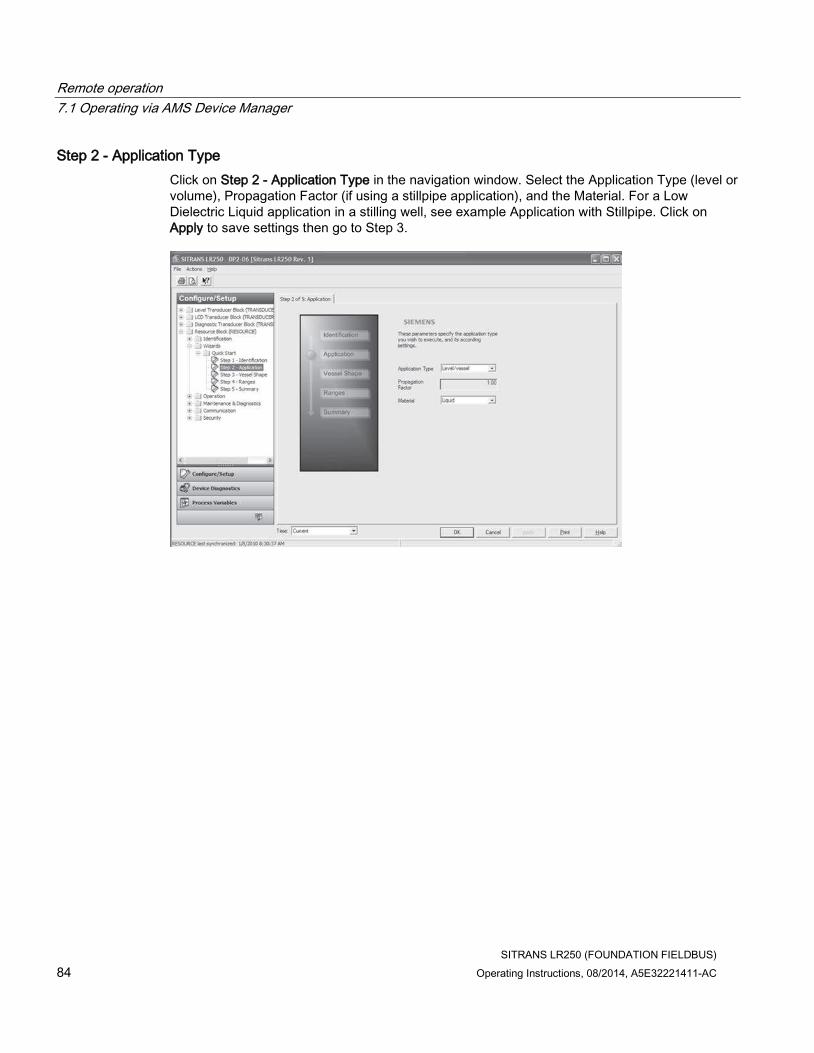
Remote operation
7.1 Operating via AMS Device Manager
SITRANS LR250 (FOUNDATION FIELDBUS)
84 Operating Instructions, 08/2014, A5E32221411-AC
Step 2 - Application Type
Click on Step 2 - Application Type in the navigation window. Select the Application Type (level or volume), Propagation Factor (if using a stillpipe application), and the Material. For a Low Dielectric Liquid application in a stilling well, see example Application with Stillpipe. Click on Apply to save settings then go to Step 3.

Remote operation
7.1 Operating via AMS Device Manager
SITRANS LR250 (FOUNDATION FIELDBUS)
Operating Instructions, 08/2014, A5E32221411-AC 85
Step 3 - Vessel Shape
Click on Step 3 - Vessel Shape in the navigation window. Select the vessel shape. To describe a more complex shape, select Linearization Table in the Vessel Shape field and see Linearization (LTB) (Page 93) for more details. Click on Apply to save settings then go to Step 4.

Remote operation
7.1 Operating via AMS Device Manager
SITRANS LR250 (FOUNDATION FIELDBUS)
86 Operating Instructions, 08/2014, A5E32221411-AC
Step 4 - Ranges
Click on Step 4 - Ranges in the navigation window. On the tab Step 4 of 5 Ranges: set the parameters, and click on Apply to save settings. If necessary, click on the Breakpoints tab, set the parameters, and click on Apply to save settings. Go to Step 5.

Remote operation
7.1 Operating via AMS Device Manager
SITRANS LR250 (FOUNDATION FIELDBUS)
Operating Instructions, 08/2014, A5E32221411-AC 87
Step 5 - Summary
Click on Step 5 - Summary in the navigation window. Check parameter settings. Return to individual steps if further changes are necessary.
The Quick Start Wizard is now complete.
7.1.8 Changing parameter settings using AMS Device Manager
Note
• For a complete list of parameters, see Parameter Reference (Page 139).
• For more detailed explanations of the parameters listed below see the pages referenced.
1. Adjust parameter values in the parameter value field in Configure/Setup view, then click on Apply to write the new values to the device. The parameter field will display in yellow until the value has been written to the device.
2. Click on OK only if you wish to update all parameters and exit device view.

Remote operation
7.1 Operating via AMS Device Manager
SITRANS LR250 (FOUNDATION FIELDBUS)
88 Operating Instructions, 08/2014, A5E32221411-AC
7.1.9 Configure/Setup (Level Transducer Block-LTB)
7.1.9.1 Identification (LTB)
Navigate to Configure/Setup > LTB > Identification.
Identification:
● TAG: Read only. Description for the associated block: device tag prefixed by block type.
● Descriptor [see Descriptor (2.1.2.)]
● Transducer Block Type: Read only. Identifies the type of transducer block.
● Strategy: Used to identify grouping of blocks.
● Plant Unit: The identification number of the plant unit. For example, can be used in the host for sorting alarms.

Remote operation
7.1 Operating via AMS Device Manager
SITRANS LR250 (FOUNDATION FIELDBUS)
Operating Instructions, 08/2014, A5E32221411-AC 89
7.1.9.2 Operation (LTB)
Navigate to Configure/Setup > LTB > Operation.
Click on Block Modes to open the dialog window for access to:
Block Modes:
● Actual Mode: This is the current mode of the block, which may differ from the target based on operating conditions. Its value is calculated as part of the block execution.
● Target Mode [see Mode (2.6.2.)]
● Permitted Mode: Defines the modes that are allowed for an instance of the block. The permitted mode is configured based on application requirements.
● Normal Mode: This is the mode that the block should be set to during normal operating conditions.
Click on Simulation to open the dialog window for access to:
Simulation (Input)
Allows you to simulate the sensor value which is input to the Level Transducer Block. This tests everything between the Level Transducer Block and Output.

Remote operation
7.1 Operating via AMS Device Manager
SITRANS LR250 (FOUNDATION FIELDBUS)
90 Operating Instructions, 08/2014, A5E32221411-AC
Note
To activate simulation via AMS Device Manager or the 375 Field Communicator, simulation must also be set to Enabled on the device. See Simulate Enable (4.12.).
● Simulation
● Simulation Value
● RAMP start
● RAMP end
● RAMP No of steps
● RAMP steplength
1. To enable simulation select Fixed value or Ramp in the Simulation field.
2. If you select Fixed value, enter a Simulation Value.
3. If you select Ramp, enter the ramp start, end, number of steps, and steplength.
4. Click Apply.
5. After simulation is complete, set Simulation to OFF and click Apply.

Remote operation
7.1 Operating via AMS Device Manager
SITRANS LR250 (FOUNDATION FIELDBUS)
Operating Instructions, 08/2014, A5E32221411-AC 91
7.1.9.3 Setup (LTB)
Sensor (LTB)
Navigate to Configure/Setup > LTB > Setup and click on Sensor for access to:
General
[see Sensor (2.3.) for details]
● Unit [see Unit (2.3.1.)]
● Level Unit [see Level Unit (2.3.2.)]
● Temperature Unit [see Temperature Units (2.3.4.)]
● PV (Volume/Level) Unit [see PV (volume/level) Units (2.3.3.)]
● Application Type (available only via AMS Device Manager)
Defines the application type.
Values
Level/vessel (default)
Level/stillpipe
Level/bypass pipe
Volume/vessel
Volume/stillpipe
Volume/bypass pipe
● Material [see Material (2.3.5.)]
● Loss of Echo Timer (see Loss of Echo (LOE) Timer (2.3.6.)]

Remote operation
7.1 Operating via AMS Device Manager
SITRANS LR250 (FOUNDATION FIELDBUS)
92 Operating Instructions, 08/2014, A5E32221411-AC
Calibration
[see Calibration (2.3.7.) for details]
● Low Calibration Point [see Low Calibration Point (2.3.7.1.)]
● High Calibration Point [see High Calibration Point 2.3.7.2.)]
● Sensor Offset [see Sensor Offset (2.3.7.3.)]
● Low Level Point [see Low Level Point (2.3.7.4.)]
● High Level Point [see High Level Point (2.3.7.5)]
● Level Offset [see Level Offset (2.3.7.6.)]
Rate
[see Rate (2.3.8.)]
● Response Rate [see Response Rate (2.3.8.1.)]
● Fill Rate per Minute [see Fill Rate per Minute (2.3.8.2.)]
● Empty Rate per Minute [see Empty Rate per Minute (2.3.8.3.)]

Remote operation
7.1 Operating via AMS Device Manager
SITRANS LR250 (FOUNDATION FIELDBUS)
Operating Instructions, 08/2014, A5E32221411-AC 93
7.1.9.4 Linearization (LTB)
You can use the linearization feature to define a more complex vessel shape and enter up to 32 level breakpoints where the corresponding volume is known. See Linearization (2.4.).
Navigate to Configure/Setup > LTB > Setup > Linearization and click on Linearization. Click on the Vessel Shape tab to access the parameters listed:
Vessel Shape
● Vessel Shape [see Vessel Shape (2.4.1.1.)]
Vessel Dimensions
● Maximum Volume [see Maximum Volume (2.4.1.2.)]
● Vessel Dimension A [see Dimension A (2.4.1.3.)]
● Vessel Dimension L [see Dimension L (2.4.1.4.)]
OR
Click on Breakpoints tab for access to level and volume breakpoints.
Note
This parameter becomes accessible only after Linearization Table has been selected in Vessel Shape above.

Remote operation
7.1 Operating via AMS Device Manager
SITRANS LR250 (FOUNDATION FIELDBUS)
94 Operating Instructions, 08/2014, A5E32221411-AC
Level and Volume Breakpoints [see XY Index (2.4.1.5.)]
● Level 1 .... Level 32
● Volume 1 ... Volume 32
● Vessel Shape
1. The default for level values is percent: if you want to select units instead, go to Configure/Setup > LTB > Setup > Sensor > Level Unit, and select the desired unit.
2. Go to Configure/Setup > LTB > Setup > Sensor > PV (Volume/Level) Unit, and select the desired volume units.
3. From the Vessel Shape tab of Configure/Setup > LTB > Setup > Linearization, select Linearization Table option in the Vessel Shape field.
4. Click on the Breakpoints tab and enter values for level and volume breakpoints in table.
The values corresponding to 100% and 0% levels must be entered. The breakpoints can be ordered from top to bottom, or the reverse.
After completing the above steps you will need to configure AIFB 1 and/or AIFB 2. [See AIFB 1 (2.6.) and AIFB 2 (2.7.)]

Remote operation
7.1 Operating via AMS Device Manager
SITRANS LR250 (FOUNDATION FIELDBUS)
Operating Instructions, 08/2014, A5E32221411-AC 95
7.1.9.5 Signal processing
Signal Processing (LTB)
Note
For more detailed explanations of the parameters listed below see the pages referenced.
General
Navigate to Configure/Setup > LTB > Setup > Signal Processing and click on General for access to:
Range
[see Signal Processing (2.5.)]
● Near Range [see Near Range (2.5.1.)]
● Far Range [see Far Range (2.5.2.)]
● Propogation Factor [see Propogation Factor (2.5.3.)]
● Minimum Sensor Value [see Minimum Sensor Value (2.5.4.)]
● Maximum Sensor Value [see Maximum Sensor Value (2.5.5.)]
Remote operation
7.1 Operating via AMS Device Manager
SITRANS LR250 (FOUNDATION FIELDBUS)
96 Operating Instructions, 08/2014, A5E32221411-AC
Echo Select
[see Echo Select (2.5.7.)]
● Algorithm [see Algorithm (2.5.7.1.)]
● Position Detect [see Position Detect (2.5.7.2.)]
● Echo Threshold [see Echo Threshold (2.5.7.3.)]
● CLEF Range [see CLEF (Contrained Leading Edge Fit) Range (2.5.7.4.)]
Sampling
[see Sampling (2.5.8.)]
● Echo Lock [see Echo Lock (2.5.8.1.)]
● Sampling Up [see Up Sampling (2.5.8.2.)]
● Sampling Down [see Down Sampling (2.5.8.3.)]
Echo Quality
[see Echo Quality (2.5.9.)]
● Confidence [see Confidence (2.5.9.1.)]
● Echo Strength [see Echo Strength (2.5.9.2.)]
● Noise Average
Displays the average ambient noise (in dB above 1 μV rms) of a noise profile. Noise level is a combination of transient noise and receiving circuitry. After a measurement, the values from the previous noise shot will be displayed.
TVT (time varying threshold)
A time-varying curve that determines the threshold level above which echoes are determined to be valid.
Modify the TVT to screen out false echoes [see Time Varying Threshold (TVT) (Page 261), and Auto False Echo Suppression (2.5.10.1.)].
Navigate to Configure/Setup > LTB > Setup > Signal Processing and click on TVT. Click on one of the two tabs to access the parameters listed:
TVT Setup
● Auto False Echo Suppression [see Auto False Echo Suppression (2.5.10.1.)]
● Auto False Echo Suppression Range [see Auto False Echo Suppression Range (2.5.10.2.)]
● Hover Level [see Hover Level (2.5.10.3.)]
● Shaper Mode [see Shaper Mode (2.5.10.4.)]

Remote operation
7.1 Operating via AMS Device Manager
SITRANS LR250 (FOUNDATION FIELDBUS)
Operating Instructions, 08/2014, A5E32221411-AC 97
Auto False Echo Suppression
1. Determine Auto False Echo Suppression Range. Measure the actual distance from the sensor reference point to the material surface using a rope or tape measure.
2. Subtract 0.5 m (20") from this distance, and use the resulting value.
3. Open the menu Configure/Setup > LTB > Setup > Signal Processing > TVT and set Auto False Echo Suppression Range.
4. From the same menu, set Auto False Echo Suppression to learn. The device will automatically revert to On (Use Learned TVT) after a few seconds.
TVT Shaper
[see TVT Shaper (2.5.11.)]
● Breakpoints 1 to 40
● Shaper Mode
1. Open the menu Configure/Setup > LTB > Setup > Signal Processing > TVT and click on the TVT Setup tab
2. Turn Shaper Mode to On to activate Breakpoints 1 to 40 on the TVT Shaper tab
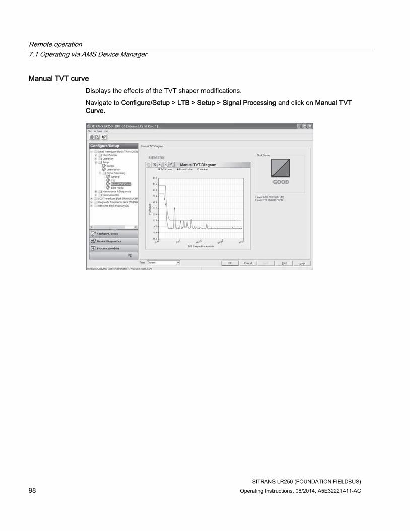
Remote operation
7.1 Operating via AMS Device Manager
SITRANS LR250 (FOUNDATION FIELDBUS)
98 Operating Instructions, 08/2014, A5E32221411-AC
Manual TVT curve
Displays the effects of the TVT shaper modifications.
Navigate to Configure/Setup > LTB > Setup > Signal Processing and click on Manual TVT Curve.

Remote operation
7.1 Operating via AMS Device Manager
SITRANS LR250 (FOUNDATION FIELDBUS)
Operating Instructions, 08/2014, A5E32221411-AC 99
Echo Profile
Displays the current echo profile.
Navigate to Configure/Setup > LTB > Setup > Signal Processing and click on Echo Profile to view the current echo profile and to access:
Echo Profile Parameters
[see Echo Profile (3.1.)]
● Level Measurement [see Measured Values (2.8)]
● Distance Measurement [see Measured Values (2.8.)]
● Confidence [see Confidence (2.5.9.1.)]
● Near Range (see (Near Range 2.5.1.)]
To view a previous profile, click the drop-down arrow on the Time field and select the desired profile (note: available only using AMS version 10.1or later).
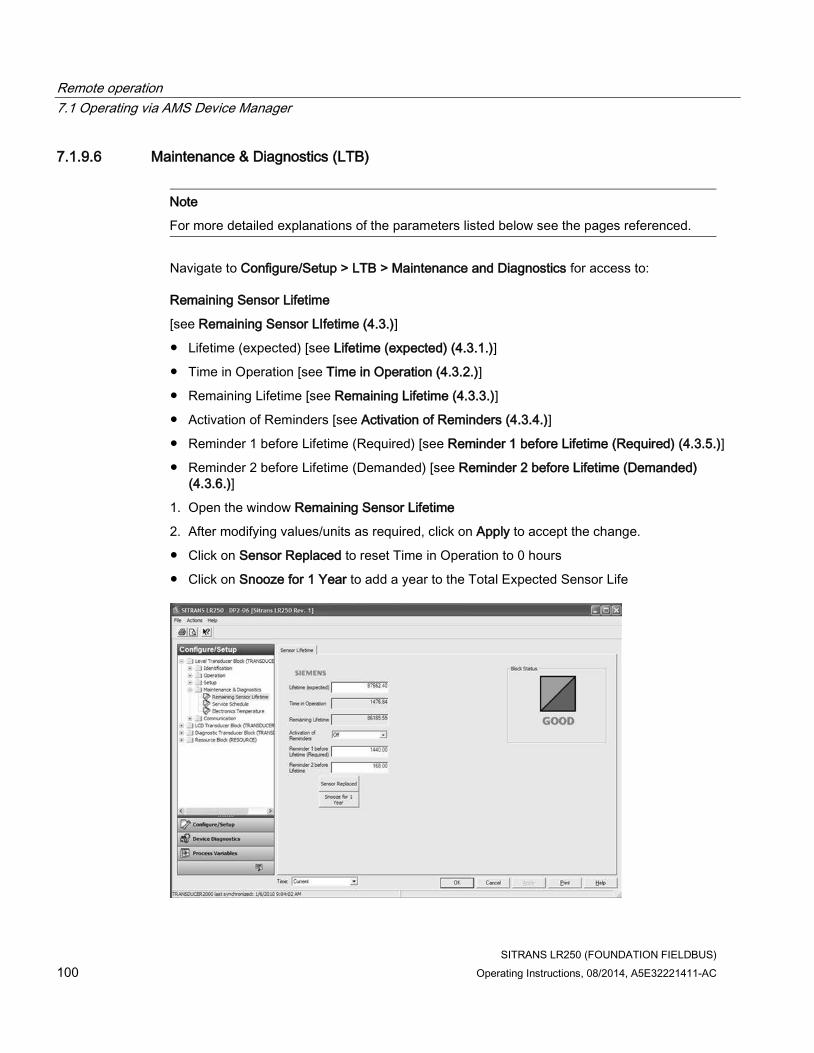
Remote operation
7.1 Operating via AMS Device Manager
SITRANS LR250 (FOUNDATION FIELDBUS)
100 Operating Instructions, 08/2014, A5E32221411-AC
7.1.9.6 Maintenance & Diagnostics (LTB)
Note
For more detailed explanations of the parameters listed below see the pages referenced.
Navigate to Configure/Setup > LTB > Maintenance and Diagnostics for access to:
Remaining Sensor Lifetime
[see Remaining Sensor LIfetime (4.3.)]
● Lifetime (expected) [see Lifetime (expected) (4.3.1.)]
● Time in Operation [see Time in Operation (4.3.2.)]
● Remaining Lifetime [see Remaining Lifetime (4.3.3.)]
● Activation of Reminders [see Activation of Reminders (4.3.4.)]
● Reminder 1 before Lifetime (Required) [see Reminder 1 before Lifetime (Required) (4.3.5.)]
● Reminder 2 before Lifetime (Demanded) [see Reminder 2 before Lifetime (Demanded) (4.3.6.)]
1. Open the window Remaining Sensor Lifetime
2. After modifying values/units as required, click on Apply to accept the change.
● Click on Sensor Replaced to reset Time in Operation to 0 hours
● Click on Snooze for 1 Year to add a year to the Total Expected Sensor Life

Remote operation
7.1 Operating via AMS Device Manager
SITRANS LR250 (FOUNDATION FIELDBUS)
Operating Instructions, 08/2014, A5E32221411-AC 101
Service Schedule
[see Service Schedule (4.4.)]
● Service Interval [see Service Interval (4.4.1.)]
● Time Since Last Service [see Time Since Last Service (4.4.2.)]
● Time Until Next Service [see Time Until Next Service (4.4.3.)]
● Activation of Reminders [see Activation of Reminders (4.4.4.)]
● Reminder 1 before Lifetime (Required) [see Reminder 1 before Service (Required) (4.4.5.)]
● Reminder 2 before Lifetime (Demanded) [see Reminder 2 before Service (Demanded) (4.4.6.)]
● Click on Service Performed to reset Time Since Last Service to 0 hours

Remote operation
7.1 Operating via AMS Device Manager
SITRANS LR250 (FOUNDATION FIELDBUS)
102 Operating Instructions, 08/2014, A5E32221411-AC
Electronics Temperature
[see Electronics Temperature (3.3.)]
● Electronics Temperature: Displays the current internal temperature of the device
● Minimum Value [see Minimum Value (3.3.1.)]
● Maximum Value [see Maximum Value (3.3.2.)]

Remote operation
7.1 Operating via AMS Device Manager
SITRANS LR250 (FOUNDATION FIELDBUS)
Operating Instructions, 08/2014, A5E32221411-AC 103
7.1.9.7 Communication (LTB)
Navigate to Configure/Setup > LTB > Communication for access to:
Communication:
● Static Revision No. [see Static Revision Number (2.6.1.)]
7.1.10 Configure/Setup (Liquid Crystal Display Block-LCD)
7.1.10.1 Identification (LCD)
Navigate to Configure/Setup > LCD > Identification.
Identification:
● TAG
● Descriptor
● Transducer Block Type
● Strategy
● Plant Unit
Note
For descriptions of Identification parameters see Identification (LTB) (Page 88).

Remote operation
7.1 Operating via AMS Device Manager
SITRANS LR250 (FOUNDATION FIELDBUS)
104 Operating Instructions, 08/2014, A5E32221411-AC
7.1.10.2 Operation (LCD)
Note
For more detailed explanations of the parameters listed below see the pages referenced.
Navigate to Configure/Setup > LCD > Operation.
Click on Block Modes to open the dialog window for access to:
Block Modes:
● Actual Mode
● Target Mode
● Permitted Mode
● Normal Mode
Note
For descriptions of Block Modes see Operation (LTB) (Page 89).
To disable updating of the LCD remotely, Actual Mode of this block should read Out of Service. This is done by setting Target Mode to Out of Service.
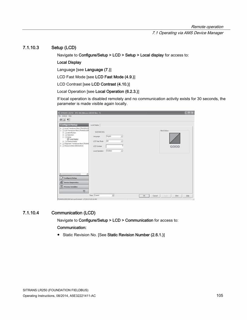
Remote operation
7.1 Operating via AMS Device Manager
SITRANS LR250 (FOUNDATION FIELDBUS)
Operating Instructions, 08/2014, A5E32221411-AC 105
7.1.10.3 Setup (LCD)
Navigate to Configure/Setup > LCD > Setup > Local display for access to:
Local Display
Language [see Language (7.)]
LCD Fast Mode [see LCD Fast Mode (4.9.)]
LCD Contrast [see LCD Contrast (4.10.)]
Local Operation [see Local Operation (6.2.3.)]
If local operation is disabled remotely and no communication activity exists for 30 seconds, the parameter is made visible again locally.
7.1.10.4 Communication (LCD)
Navigate to Configure/Setup > LCD > Communication for access to:
Communication:
● Static Revision No. [See Static Revision Number (2.6.1.)]

Remote operation
7.1 Operating via AMS Device Manager
SITRANS LR250 (FOUNDATION FIELDBUS)
106 Operating Instructions, 08/2014, A5E32221411-AC
7.1.11 Configure/Setup (Diagnostic Transducer Block-DIAG)
Note
Parameters in the Diagnostic Transducer Block used solely by factory personnel.
7.1.11.1 Identification (DIAG)
Navigate to Configure/Setup > DIAG > Identification.
Identification:
● TAG
● Descriptor
● Transducer Block Type
● Strategy
● Plant Unit
Note
For descriptions of Identification parameters see Identification (LTB) (Page 88).
7.1.11.2 Operation (DIAG)
Navigate to Configure/Setup > DIAG > Operation.
Block Modes:
● Actual Mode
● Target Mode
● Permitted Mode
● Normal Mode
Note
For descriptions of Block Modes see Operation (LTB) (Page 89).
7.1.11.3 Communication (DIAG)
Navigate to Configure/Setup > DIAG > Communication.
Communication:
● Static Revision No. [see Static Revision Number (2.6.1.)]

Remote operation
7.1 Operating via AMS Device Manager
SITRANS LR250 (FOUNDATION FIELDBUS)
Operating Instructions, 08/2014, A5E32221411-AC 107
7.1.12 Configure/Setup (Resource Block - RESOURCE)
Note
For more detailed explanations of the parameters listed below see the pages referenced.
7.1.12.1 Identification (RESOURCE)
Navigate to Configure/Setup > RESOURCE > Identification for access to:
Identification
● TAG: Read only. Description for the associated block: device tag prefixed by block type.
● Descriptor [see Descriptor (2.1.2.)]
● Message [see Message (2.1.3.)]
● Date (Installation Date): The user entered date on which the device was installed in the system.
● Strategy: Used to identify grouping of blocks.
● Plant Unit: The identification number of the plant unit. For example, can be used in the host for sorting alarms.
Device (read only)
● Manufacturer (see Manufacturer (5.3.)]
● Product Name: The manufacturer’s product name for this device.
● Order Number: The manufacturer’s order number (MLFB) for this device.
● Serial Number: The manufacturer’s unique serial number for this device.
● Hardware Revision [see Hardware Revision (2.2.1.)]
● Firmware Revision [see Firmware Revision (2.2.2.)]
● Loader Revision [see Loader Revision (2.2.3.)]
● EDD Version: The version of the EDD currently installed.
● Date of Manufacturing [see Manufacture Date (4.6.)]
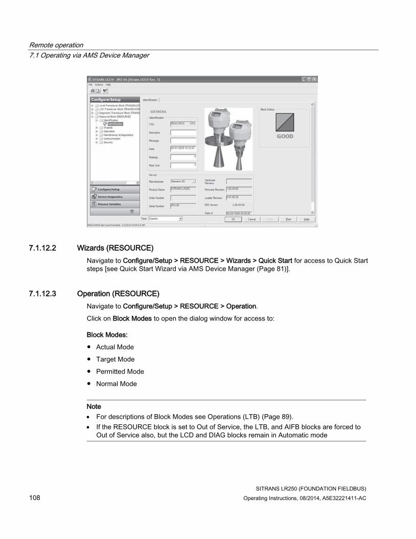
Remote operation
7.1 Operating via AMS Device Manager
SITRANS LR250 (FOUNDATION FIELDBUS)
108 Operating Instructions, 08/2014, A5E32221411-AC
7.1.12.2 Wizards (RESOURCE)
Navigate to Configure/Setup > RESOURCE > Wizards > Quick Start for access to Quick Start steps [see Quick Start Wizard via AMS Device Manager (Page 81)].
7.1.12.3 Operation (RESOURCE)
Navigate to Configure/Setup > RESOURCE > Operation.
Click on Block Modes to open the dialog window for access to:
Block Modes:
● Actual Mode
● Target Mode
● Permitted Mode
● Normal Mode
Note
• For descriptions of Block Modes see Operations (LTB) (Page 89).
• If the RESOURCE block is set to Out of Service, the LTB, and AIFB blocks are forced to Out of Service also, but the LCD and DIAG blocks remain in Automatic mode
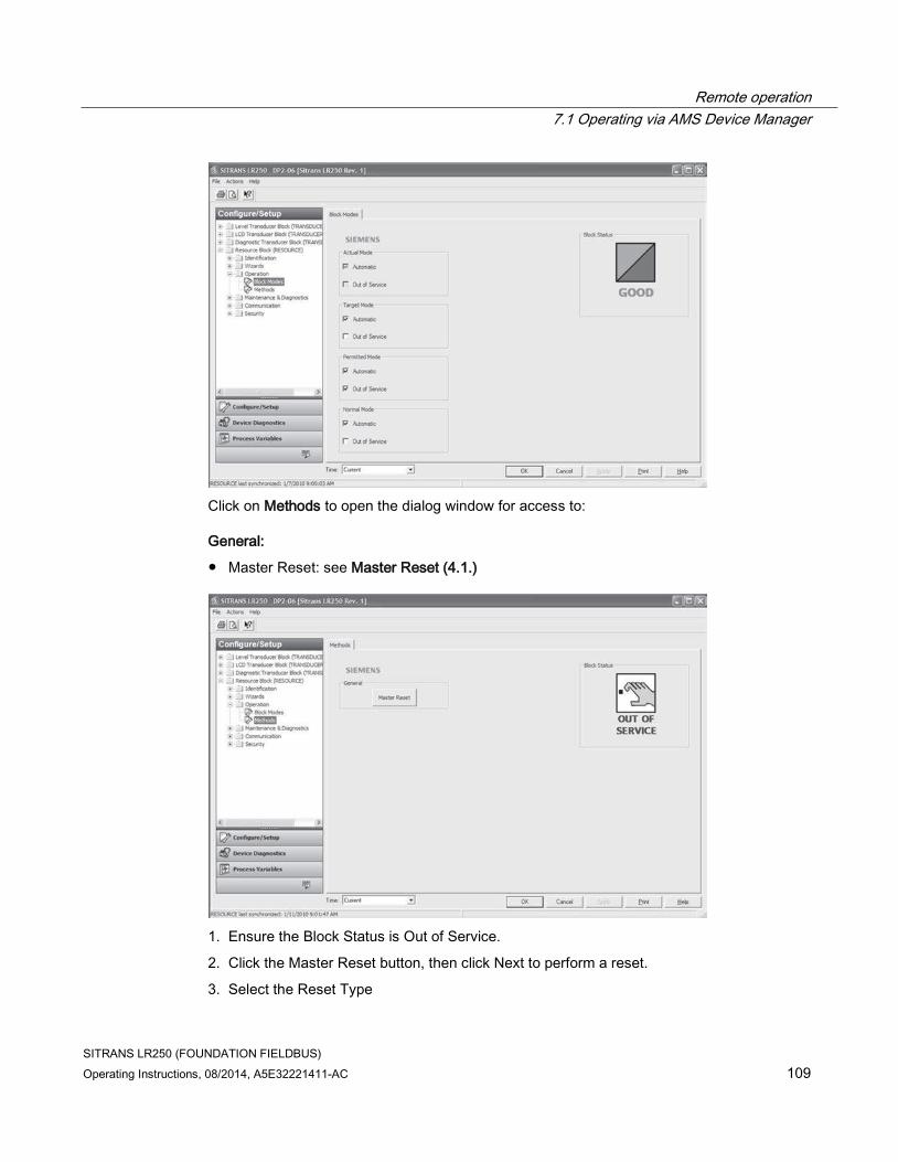
Remote operation
7.1 Operating via AMS Device Manager
SITRANS LR250 (FOUNDATION FIELDBUS)
Operating Instructions, 08/2014, A5E32221411-AC 109
Click on Methods to open the dialog window for access to:
General:
● Master Reset: see Master Reset (4.1.)
1. Ensure the Block Status is Out of Service.
2. Click the Master Reset button, then click Next to perform a reset.
3. Select the Reset Type

Remote operation
7.1 Operating via AMS Device Manager
SITRANS LR250 (FOUNDATION FIELDBUS)
110 Operating Instructions, 08/2014, A5E32221411-AC
Note
The following parameters are not reset by any reset type: Write Protection, PIN to Unlock, Auto False Echo Suppression Range, Learned TVT.
Reset Type Result
Factory Defaults a) Default. Resets all user parameters to the manufacturer’s default settings. Following this type of reset, complete reprogramming is required.
Standard Defaults Resets all parameters to standard default settings.
Informational Resets parameters such as Block Descriptor, Strategy, Device Install Date, Device Message.
Functional a) Resets parameters that control device behavior and functionality (such as Low Calibration Point).
Warm Start Has the same effect as recycling power to the device.
FF Object Dictionary Resets the FF standard block profile parameters (such as block tags) to their specified defaults. This option also clears any function block parameters and device schedule b) set by the user.
a) The only difference between Factory Defaults and Functional reset is that Factory Defaults resets maintenance parameters, such as device and sensor wear, calibration and maintenance timers. Functional reset does not reset these parameters.
b) See Data transmission in manual Foundation Fieldbus for Level Instruments (7ML19985MP01) for further details.
4. Click Next, then FINISH to complete the Master Reset.

Remote operation
7.1 Operating via AMS Device Manager
SITRANS LR250 (FOUNDATION FIELDBUS)
Operating Instructions, 08/2014, A5E32221411-AC 111
7.1.12.4 Maintenance & Diagnostics (RESOURCE)
Navigate to Configure/Setup > RESOURCE > Maintenance & Diagnostics for access to:
Remaining Device Lifetime
[see Remaining Device Lifetime (4.2.)]
● Lifetime (expected) [see Lifetime (expected (4.2.1.)]
● Remaining Lifetime (read only) [see Remaining Lifetime (4.2.3.)]
● Time in Operation (read only) [see Time in Operation (4.2.2.)]
● Activation of Reminders [see Activation of Reminders (4.2.4.)]
● Reminder 1 before Lifetime (Required) [see Reminder 1 before Lifetime (Required) (4.2.5.)]
● Reminder 2 before Lifetime (Demanded) [see Reminder 2 before Lifetime (Demanded) (4.2.6.)]
1. Open the window Remaining Device Lifetime
2. After modifying values/units as required, click on Apply to accept the change.
● Click on Snooze for 1 Year to add a year to the Total Expected Device Life.

Remote operation
7.1 Operating via AMS Device Manager
SITRANS LR250 (FOUNDATION FIELDBUS)
112 Operating Instructions, 08/2014, A5E32221411-AC
Calibration Schedule
[see Calibration Schedule (4.5)]
● Calibration Interval [see Calibration Interval (4.5.1.)]
● Time Since Last Calibration [see Time Since Last Calibration (4.5.2.)]
● Time Until Next Calibration (read only) [see Time Until Next Calibration (4.5.3.)]
● Activation of Reminders [see Activation of Reminders (4.5.4.)]
● Reminder 1 before Calibration (Required) [see Reminder 1 before Calibration (Required) (4.5.5.)]
● Reminder 2 before Calibration (Demanded) [see Reminder 2 before Calibration (Demanded) (4.5.6.)]
● Click on Calibration Performed to reset Time Since Last Calibration to 0 hours.
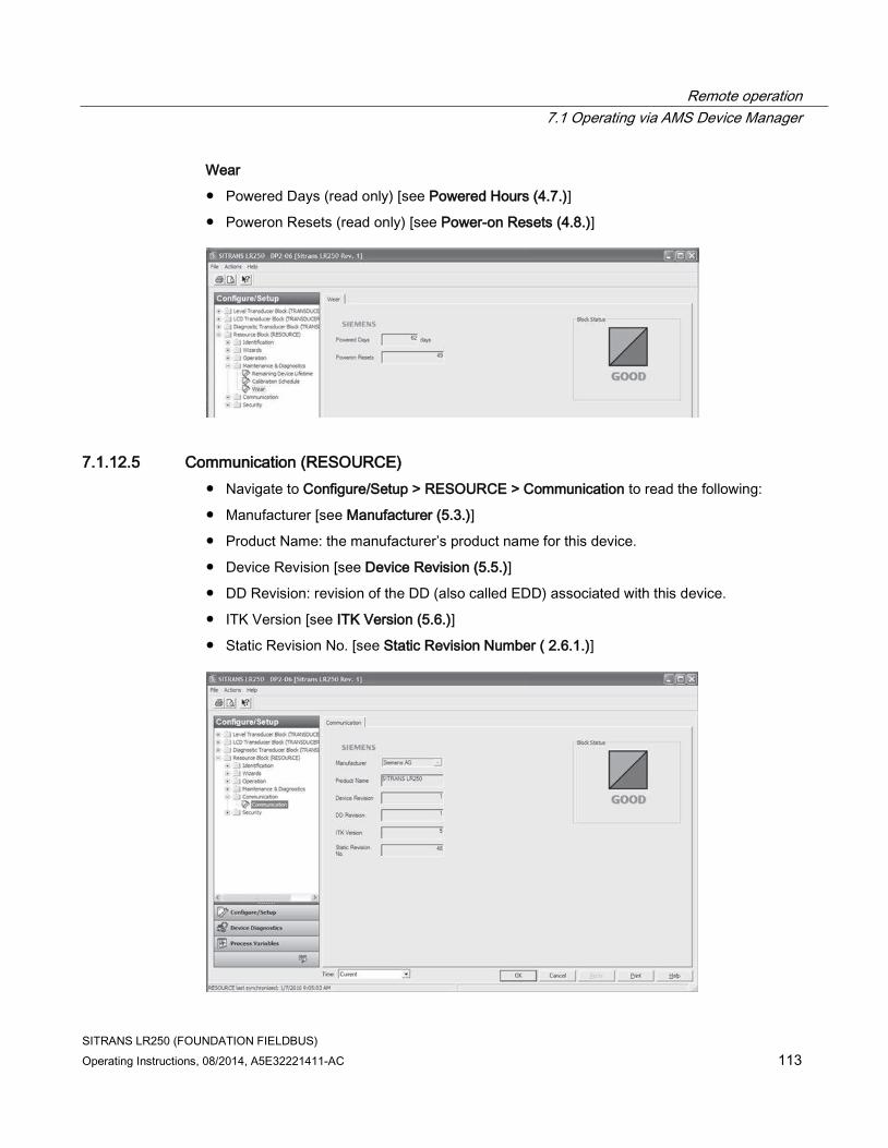
Remote operation
7.1 Operating via AMS Device Manager
SITRANS LR250 (FOUNDATION FIELDBUS)
Operating Instructions, 08/2014, A5E32221411-AC 113
Wear
● Powered Days (read only) [see Powered Hours (4.7.)]
● Poweron Resets (read only) [see Power-on Resets (4.8.)]
7.1.12.5 Communication (RESOURCE)
● Navigate to Configure/Setup > RESOURCE > Communication to read the following:
● Manufacturer [see Manufacturer (5.3.)]
● Product Name: the manufacturer’s product name for this device.
● Device Revision [see Device Revision (5.5.)]
● DD Revision: revision of the DD (also called EDD) associated with this device.
● ITK Version [see ITK Version (5.6.)]
● Static Revision No. [see Static Revision Number ( 2.6.1.)]

Remote operation
7.1 Operating via AMS Device Manager
SITRANS LR250 (FOUNDATION FIELDBUS)
114 Operating Instructions, 08/2014, A5E32221411-AC
7.1.12.6 Security (RESOURCE)
Navigate to Configure/Setup > RESOURCE > Security to access:
Local Access
● Local Write Protected [see Write Protection (6.2.1.)]
● PIN to Unlock [see PIN to Unlock (6.2.2.)]
See also Password Protection (Page 124).
7.1.13 Device Diagnostics (Level Transducer Block - LTB)
Note
For explanations of the alarms and errors listed below, see Parameter Description charts for the respective block in manual Foundation Fieldbus for Level Instruments (7ML19985MP01).

Remote operation
7.1 Operating via AMS Device Manager
SITRANS LR250 (FOUNDATION FIELDBUS)
Operating Instructions, 08/2014, A5E32221411-AC 115
7.1.13.1 Alarms & Errors (LTB)
Navigate to Device Diagnostics > LTB > Alarms & Errors.
Click on Block Error to open the dialog window to read the following:
Failures
● Input Failure
● Output Failure
● Memory Failure
● Lost Static Data
● Lost Non-Volatile Data
● Readback Check
● Device Fault State
● Block Configuration
● Link Configuration
● Other
Maintenance
● Maintenance Required
● Maintenance Demanded
Information
● Simulation Active
● Local Override
● Power Up
● Out of Service
XD Error
● Transducer Error
Click on Block Alarm to open the dialog window to read the following:
Unacknowledged
● Unacknowledged
Alarm State
● Alarm State

Remote operation
7.1 Operating via AMS Device Manager
SITRANS LR250 (FOUNDATION FIELDBUS)
116 Operating Instructions, 08/2014, A5E32221411-AC
Time Stamp
● Time Stamp
Subcode
● Subcode
Value
● Value
1. From the Block Error tab, check the Maintenance window to display the level of maintenance alarm that is active.
2. From the Block Alarm tab, check the Alarm State window to display the level of maintenance alarm that has been acknowledged.
3. From the Block Alarm tab, in the Unacknowledged window, select Acknowledged to acknowledge an alert.
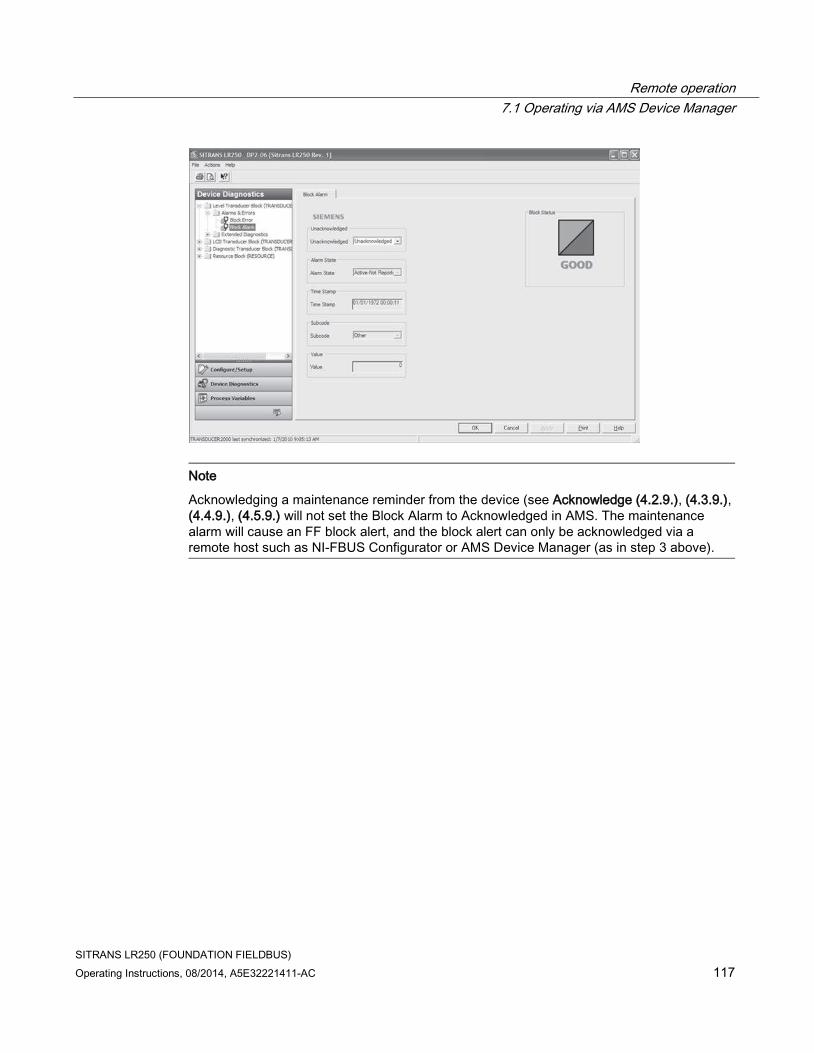
Remote operation
7.1 Operating via AMS Device Manager
SITRANS LR250 (FOUNDATION FIELDBUS)
Operating Instructions, 08/2014, A5E32221411-AC 117
Note
Acknowledging a maintenance reminder from the device (see Acknowledge (4.2.9.), (4.3.9.), (4.4.9.), (4.5.9.) will not set the Block Alarm to Acknowledged in AMS. The maintenance alarm will cause an FF block alert, and the block alert can only be acknowledged via a remote host such as NI-FBUS Configurator or AMS Device Manager (as in step 3 above).

Remote operation
7.1 Operating via AMS Device Manager
SITRANS LR250 (FOUNDATION FIELDBUS)
118 Operating Instructions, 08/2014, A5E32221411-AC
7.1.13.2 Extended Diagnostics (LTB)
Navigate to Device Diagnostics > LTB > Extended Diagnostics to read the following:
Detailed Error Info
● Loss of Echo
● No Tech Power
● Sensor Lifetime Limit1
● Sensor Lifetime Limit2
● Device Service Limit1
● Device Service Limit2
● LTB Scale
● Internal Temp Sensor
● Internal Temp High
● Internal Temperature Calibration
● Velocity Calibration
● Receiver Init Calibration
● Receiver Calibration
● Tech Module Hardware
● Tech Module Ramp
● Receiver Frequency Calibration
● Safe Process Data Corrupt
● Profile Clipped
● Too Few Shots Taken
● Measurement Error
● No Shots Taken
● Measurement Was Corrupted
● DMA Error
● Sensor Value too High
● Sensor Value too Low

Remote operation
7.1 Operating via AMS Device Manager
SITRANS LR250 (FOUNDATION FIELDBUS)
Operating Instructions, 08/2014, A5E32221411-AC 119
7.1.14 Device Diagnostics (Liquid Crystal Display Block - LCD)
7.1.14.1 Alarms & Errors (LCD)
Navigate to Device Diagnostics > LCD > Alarms & Errors to read Block and Alarm errors. [Errors displayed are the same for each block (LTB, LCD, DIAG, RESOURCE). See Alarms & Errors (LTB) (Page 115) for full listing.]
7.1.15 Device Diagnostics (Diagnostic Transducer Block - DIAG)
7.1.15.1 Alarms & Errors (DIAG)
Navigate to Device Diagnostics > DIAG > Alarms & Errors to read Block and Alarm errors. [Errors displayed are the same for each block (LTB, LCD, DIAG, RESOURCE). See Alarms & Errors (LTB) (Page 115) for full listing. See AMS Device Manager instruction manual to work with alarms and errors.]
7.1.16 Device Diagnostics (Resource Block - RESOURCE)
7.1.16.1 Alarms & Errors (RESOURCE)
Navigate to Device Diagnostics > RESOURCE > Alarms & Errors.
Click on Block Error tab to open the dialog window to read the following:
Failures
● Input Failure
● Output Failure
● Memory Failure
● Lost Static Data
● Lost Non-Volatile Data
● Readback Check
● Device Fault State
● Block Configuration
● Link Configuration
● Other

Remote operation
7.1 Operating via AMS Device Manager
SITRANS LR250 (FOUNDATION FIELDBUS)
120 Operating Instructions, 08/2014, A5E32221411-AC
Maintenance
● Maintenance Required
● Maintenance Demanded
Information
● Simulation Active
● Local Override
● Power Up
● Out of Service
Click on Block Alarm tab to open the dialog window to read the following:
Unacknowledged
● Unacknowledged
Alarm State
● Alarm State
Time Stamp
● Time Stamp
Subcode
● Subcode
Value
● Value
Values available on Block Alarm tab are also available for Write Alarm with one exception: the Value parameter on the Write Alarm tab is a Discrete Value. Click on Alarm Summary tab to open the dialog window to read the following:
Current
● Discrete Alarm
● Block Alarm
Unacknowledged
● Discrete Alarm Unacknowledged
● Block Alarm Unacknowledged

Remote operation
7.1 Operating via AMS Device Manager
SITRANS LR250 (FOUNDATION FIELDBUS)
Operating Instructions, 08/2014, A5E32221411-AC 121
Unreported
● Discrete Alarm Unreported
● Block Alarm Unreported
Disabled
● Write Alarm Disabled
● Block Alarm Disabled
7.1.16.2 Extended Diagnostics (RESOURCE)
Navigate to Device Diagnostics > RESOURCE > Extended Diagnostics to read the following:
Detailed Error Info
● Device Lifetime Limit1
● Device Lifetime Limit2
● Calibration Schedule Limit1
● Calibration Schedule Limit2
● Memory RAM
● Memory EEPROM
● Memory EEPROM Flags
● Memory Flash

Remote operation
7.1 Operating via AMS Device Manager
SITRANS LR250 (FOUNDATION FIELDBUS)
122 Operating Instructions, 08/2014, A5E32221411-AC
● Corrupt Stack
● High Stack
● Data Safe Read
● Data Safe Write
● Board Voltage
● ADC Failed
● Seq. Corrupt
● Seq. CP
● Seq. Duration
● BC Corrupt
● BC Start
● BC Stop
● BC Duration
● CPU Fault
● Data Bus
● Addr Bus
● Spurious SW Interrupt
● Spurious HW Interrupt
● Time Base Failure
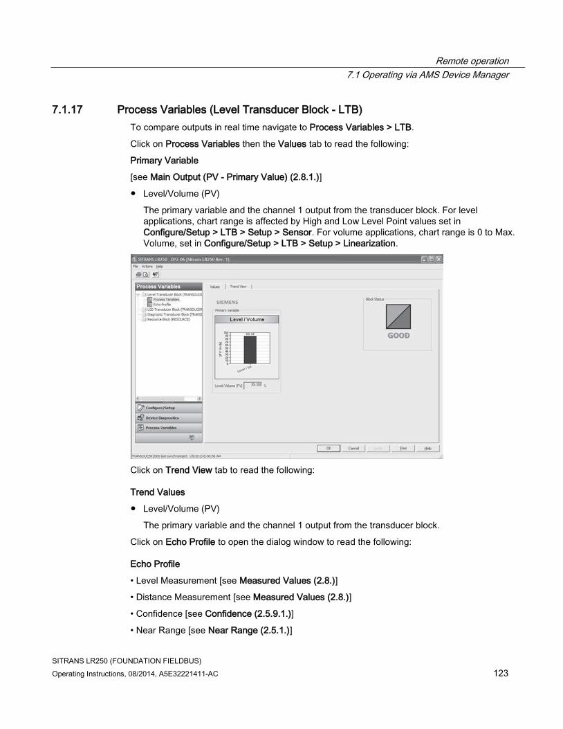
Remote operation
7.1 Operating via AMS Device Manager
SITRANS LR250 (FOUNDATION FIELDBUS)
Operating Instructions, 08/2014, A5E32221411-AC 123
7.1.17 Process Variables (Level Transducer Block - LTB)
To compare outputs in real time navigate to Process Variables > LTB.
Click on Process Variables then the Values tab to read the following:
Primary Variable
[see Main Output (PV - Primary Value) (2.8.1.)]
● Level/Volume (PV)
The primary variable and the channel 1 output from the transducer block. For level applications, chart range is affected by High and Low Level Point values set in Configure/Setup > LTB > Setup > Sensor. For volume applications, chart range is 0 to Max. Volume, set in Configure/Setup > LTB > Setup > Linearization.
Click on Trend View tab to read the following:
Trend Values
● Level/Volume (PV)
The primary variable and the channel 1 output from the transducer block.
Click on Echo Profile to open the dialog window to read the following:
Echo Profile
• Level Measurement [see Measured Values (2.8.)]
• Distance Measurement [see Measured Values (2.8.)]
• Confidence [see Confidence (2.5.9.1.)]
• Near Range [see Near Range (2.5.1.)]

Remote operation
7.1 Operating via AMS Device Manager
SITRANS LR250 (FOUNDATION FIELDBUS)
124 Operating Instructions, 08/2014, A5E32221411-AC
7.1.18 Password Protection
7.1.18.1 User Manager utility
Usernames, passwords, and permissions, are assigned to users by an AMS Device Manager administrator, using the User Manager utility on the Server Plus Station. Only a user with AMS Device Manager System Administration rights can log in to User Manager.
To configure a new user/edit existing user:
1. From the Windows taskbar select: Start > AMS Device Manager > User Manager.
2. In the User Manager window click on Add User.
The Add User Wizard dialog allows you to:
● select a user type, standard (AMS Device Manager) or Window user.
● enter the username and password, and set permissions
● edit existing users
An AMS Device Manager administrator can configure the user to require a password. The use of passwords is recommended. A password should be assigned to the ’admin’ username immediately after installing AMS Device Manager.
Each user is given an AMS Device Manager username and password and required to enter them when they start AMS Device Manager. Access to functions depends on the level of permissions granted.
Login types
● standard, local, or domain

Remote operation
7.1 Operating via AMS Device Manager
SITRANS LR250 (FOUNDATION FIELDBUS)
Operating Instructions, 08/2014, A5E32221411-AC 125
A standard user can change their password in AMS Device Manager. A Local or Domain Windows user cannot change their password using AMS Device Manager and must request their network administrator to do so.

Remote operation
7.1 Operating via AMS Device Manager
SITRANS LR250 (FOUNDATION FIELDBUS)
126 Operating Instructions, 08/2014, A5E32221411-AC
7.1.19 AMS menu structure

Remote operation
7.1 Operating via AMS Device Manager
SITRANS LR250 (FOUNDATION FIELDBUS)
Operating Instructions, 08/2014, A5E32221411-AC 127

Remote operation
7.1 Operating via AMS Device Manager
SITRANS LR250 (FOUNDATION FIELDBUS)
128 Operating Instructions, 08/2014, A5E32221411-AC

Remote operation
7.1 Operating via AMS Device Manager
SITRANS LR250 (FOUNDATION FIELDBUS)
Operating Instructions, 08/2014, A5E32221411-AC 129
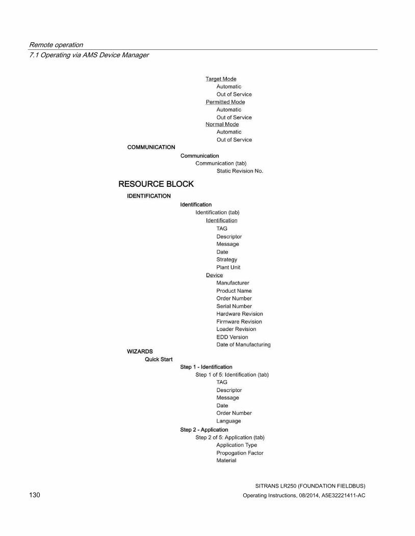
Remote operation
7.1 Operating via AMS Device Manager
SITRANS LR250 (FOUNDATION FIELDBUS)
130 Operating Instructions, 08/2014, A5E32221411-AC

Remote operation
7.1 Operating via AMS Device Manager
SITRANS LR250 (FOUNDATION FIELDBUS)
Operating Instructions, 08/2014, A5E32221411-AC 131

Remote operation
7.1 Operating via AMS Device Manager
SITRANS LR250 (FOUNDATION FIELDBUS)
132 Operating Instructions, 08/2014, A5E32221411-AC

Remote operation
7.1 Operating via AMS Device Manager
SITRANS LR250 (FOUNDATION FIELDBUS)
Operating Instructions, 08/2014, A5E32221411-AC 133

Remote operation
7.1 Operating via AMS Device Manager
SITRANS LR250 (FOUNDATION FIELDBUS)
134 Operating Instructions, 08/2014, A5E32221411-AC

Remote operation
7.1 Operating via AMS Device Manager
SITRANS LR250 (FOUNDATION FIELDBUS)
Operating Instructions, 08/2014, A5E32221411-AC 135

Remote operation
7.1 Operating via AMS Device Manager
SITRANS LR250 (FOUNDATION FIELDBUS)
136 Operating Instructions, 08/2014, A5E32221411-AC
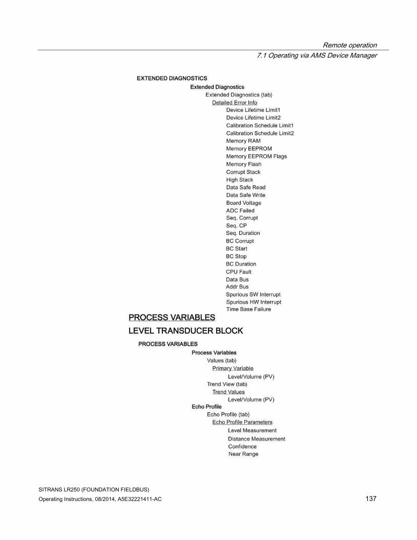
Remote operation
7.1 Operating via AMS Device Manager
SITRANS LR250 (FOUNDATION FIELDBUS)
Operating Instructions, 08/2014, A5E32221411-AC 137

Remote operation
7.1 Operating via AMS Device Manager
SITRANS LR250 (FOUNDATION FIELDBUS)
138 Operating Instructions, 08/2014, A5E32221411-AC

SITRANS LR250 (FOUNDATION FIELDBUS)
Operating Instructions, 08/2014, A5E32221411-AC 139
Parameter reference 8
Note
• See Enter PROGRAM mode under LCD Display (Page 55) for detailed instructions.
• To view a particular parameter in AMS, see Operating via AMS Device Manager (Page 75).
• Do not use the handheld programmer at the same time as AMS Device Manager, or erratic operation may result.
• For Quick Access to parameters via the handheld programmer, press Home , then
enter the menu number, for example: 2.2.1. to access parameter Hardware Revision
(2.2.1.).
• In Navigation mode, ARROW keys ( ) navigate the menu in the direction of
the arrow.
• Press RIGHT arrow to open Edit Mode, or to save a modification.
Parameters are identified by name and organized into function groups. Menus arranged on up to four levels give access to associated features and options. See LCD menu structure (Page 289) for a chart.
Parameters noted as Read Only in this section of the manual can not be written via the LUI, however they may be accessible via other tools. For those accessible via AMS Device Manager, directions are shown in section Operating via AMS Device Manager on the pages referenced.
Quick Start Wizard
The Quick Start Wizard groups together all the settings you need to configure a device for a simple application. You can access it either via AMS Device Manager or via the handheld programmer.
● Do not use the Quick Start Wizard via the handheld programmer to modify individual parameters. (Perform customization only after the Quick Start has been completed.)
● Each time the Quick Start Wizard is initiated via the handheld programmer, the startup settings are factory defaults. The Wizard will not recall previous user-defined settings. (Note: Values set using the Quick Start Wizard via AMS Device Manager are saved and recalled each time it is initiated.)
● When using AMS Device Manager, the Resource and LTB Blocks must be set to Out of Service mode before any configuration changes (changes to parameters affecting block output) can be written. The blocks do not need to be set to Out of Service when the Quick Start Wizard is initiated via the handheld programmer.
Parameter reference
SITRANS LR250 (FOUNDATION FIELDBUS)
140 Operating Instructions, 08/2014, A5E32221411-AC
Quick Start (1.)
Note
For detailed instructions see Quick Start Wizard via the handheld programmer (Page 63) or Quick Start Wizard via AMS Device Manager (Page 81).
Setup (2.)
Note
• See Parameter menus (Page 58) or Operating via AMS Device Manager (Page 75) for instructions.
• Default settings in the parameter tables are indicated with an asterisk (*) unless explicitly stated.
• Values shown in the following tables can be entered via the handheld programmer.
Identification (2.1.)
Tag (2.1.1.)
Read only. Text that can be used in any way. A recommended use is as a unique label for a field device in a plant. Limited to 32 ASCII characters.
Note
The tag can only be changed from a remote master such as NIFBUS-Configurator or DeltaV.
Descriptor (2.1.2.)
Read only. Text that can be used in any way. Limited to 32 ASCII characters. No specific recommended use.
To access this parameter via AMS Device Manager see Identification under Identification (RESOURCE) (Page 107).
Message (2.1.3.)
Read only. Text that can be used in any way. Limited to 32 ASCII characters. No specific recommended use.
To access this parameter via AMS Device Manager see Identification under Identification (RESOURCE). (Page 107)

Parameter reference
SITRANS LR250 (FOUNDATION FIELDBUS)
Operating Instructions, 08/2014, A5E32221411-AC 141
Device (2.2.)
Hardware Revision (2.2.1.)
Read only. Corresponds to the electronics hardware of the Field Device.
Firmware Revision (2.2.2.)
Read only. Corresponds to the software or firmware that is embedded in the Field Device.
Loader Revision (2.2.3.)
Read only. Corresponds to the software used to update the Field Device.
Sensor (2.3.)
Unit (2.3.1)
Sensor measurement unit.
Values m, cm, mm, ft, in
* m
Level Unit (2.3.2.)
Select engineering units for Level.
Options m, cm, mm, ft, in, %
* %
Parameter reference
SITRANS LR250 (FOUNDATION FIELDBUS)
142 Operating Instructions, 08/2014, A5E32221411-AC
PV Units (volume/level) (2.3.3.)
Note
• Default unit of AIFB 1 or 2 is percent.
• You can select a different unit for your application.
• PV (Primary Value): the output from the Level Transducer Block. See Level Transducer Block (LTB) and How the LTB works: in manual Foundation Fieldbus for Level Instruments (7ML19985MP01) for more details.
Select units for either volume or level.
Level values m, cm, mm, ft, in, %
Volume values liter, gal, ImpGal, %
Percent value * %
Temperature Units (2.3.4.)
Selects the engineering unit to be displayed with the value representing temperature.
Options DEGC, DEGF, DEGR, K
* DEGC
Material (2.3.5.)
Automatically configures the device to operate in the chosen application type, by changing one or more of the following parameters: Propagation Factor (2.5.3.), Position Detect (2.5.7.2.), and/or CLEF Range (2.5.7.4.).
Options * LIQUID
LIQUID LOW DK a) (low dielectric liquid - CLEF algorithm enabled)
Related parameters Propagation Factor (2.5.3.)
Position Detect (2.5.7.2.)
CLEF Range (2.5.7.4.)
a) dK < 3.0
You can configure each of the related parameters, to suit your particular application.

Parameter reference
SITRANS LR250 (FOUNDATION FIELDBUS)
Operating Instructions, 08/2014, A5E32221411-AC 143
LOE Timer (2.3.6.)
Note
See Loss of Echo (LOE) (Page 268) for more detail.
Sets the time to elapse since the last valid reading, before the Fail-safe material level is reported.
Values Range: 0 to 7200 seconds
Default: 100 s
Calibration (2.3.7)
Low Calibration Pt. (2.3.7.1.)
Distance from sensor reference point to Low Calibration Point (corresponding to Low Level Point). Units are defined in Unit (2.3.1.).
① High level point (default 100%) ⑥ Level offset (if used)
② Low level point (0%) ⑦ Low calibration point
③ Sensor value ⑧ Sensor reference point a)
④ High calibration point ⑨ Far range
⑤ Level
a) The point from which level measurement is referenced [see Flat Faced Flange (Page 252) and Threaded Horn Antenna with extension (Page 215) and Flanged encapsulated antenna (3"/DN80/80A sizes and larger). (Page 226) ].
Values Range: 0.00 to 20.00 m. Default 20.00 m
Related parameters Unit (2.3.1.) Far Range (2.5.2.)

Parameter reference
SITRANS LR250 (FOUNDATION FIELDBUS)
144 Operating Instructions, 08/2014, A5E32221411-AC
High Calibration Point (2.3.7.2.)
Distance from sensor reference point 1) to High Calibration Point (corresponding to High Level Point). Units are defined in Unit (2.3.1.). See Low Calibration Point (2.3.7.1.) for an illustration.
Values Range: 0.00 to 20.00 m. Default 0.00 m
Related parameters Unit (2.3.1.), Near Range (2.5.1.)
When setting the High Calibration Point value, note that echoes are ignored within Near Range (2.5.1.).
1) The value produced by the echo processing which represents the distance from sensor reference point to the target. [see Threaded Horn Antenna with extension, (Page 218) Flanged Horn with extension (Page 222), and Flanged encapsulated antenna (3"/DN80/80A sizes and larger) (Page 226)].
Sensor Offset (2.3.7.3.)
A constant offset that can be added to or subtracted from the sensor value to compensate for a shifted sensor reference point. (For example, when adding a thicker gasket or reducing the standoff/nozzle height.) The units are defined in Unit (2.3.1.).
Values
Range: -99.999 to 99.999 Default: 0.000 m
Related Parameters Unit (2.3.1.)
See How the LTB works: in manual Foundation Fieldbus for Level Instruments (7ML19985MP01) for more details on sensor offset.
Low Level Point (2.3.7.4.)
The level when the material is at Low Calibration Point. The unit is defined in Level Unit (2.3.2.).
Values Range: -999999 to 999999
Default: 0%
High Level Point (2.3.7.5.)
The level when the material is at High Calibration Point. The unit is defined in Level Unit (2.3.2.).
Values Range: -999999 to +999999
Default: 100%

Parameter reference
SITRANS LR250 (FOUNDATION FIELDBUS)
Operating Instructions, 08/2014, A5E32221411-AC 145
Level Offset (2.3.7.6.)
A constant offset that can be added to Level. The unit is defined in Level Unit (2.3.2.).
Values Range: -999999 to +999999
Default: 0%
Rate (2.3.8.)
Response Rate (2.3.8.1.)
Sets the reaction speed of the device to measurement changes.
Note
Changing Response Rate resets Fill Rate per Minute (2.3.8.2), Empty rate per Minute (2.3.8.3), and Shots (2.5.6.).
Response Rate (2.3.8.1.) Fill Rate per Minute (2.3.8.2.)/ Empty rate per Minute (2.3.8.3.)
Shots (2.5.6.)
* Slow 0.1 m/min (0.32 ft/min) 25
Medium 1.0 m/min (3.28 ft/min) 10
Fast 10.0 m/min (32.8 ft/min) 5
Use a setting just faster than the maximum filling or emptying rate (whichever is faster).
Fill Rate per Minute (2.3.8.2.)
Defines the maximum rate at which the reported sensor value is allowed to decrease. Allows you to adjust the SITRANS LR250 response to decreases in the actual material level. Fill Rate is automatically updated whenever Response Rate (2.3.8.1.) is altered.
Sensor value is the value produced by the echo processing which represents the distance from sensor reference point to the target [see Low Calibration Point (2.3.7.1.) for an illustration].
Options Range: 0 to 999999 m / min.
Response Rate (2.3.8.1.) Fill Rate per Minute (2.3.8.2.)
* Slow 0.1 m/min (0.32 ft/min)
Medium 1.0 m/min (3.28 ft/min)
Fast 10.0 m/min (32.8 ft/min)
Altered by: Response Rate (2.3.8.1.)
Related parameters Level Unit (2.3.2.)
Enter a value slightly greater than the maximum vessel-filling rate, in units per minute.
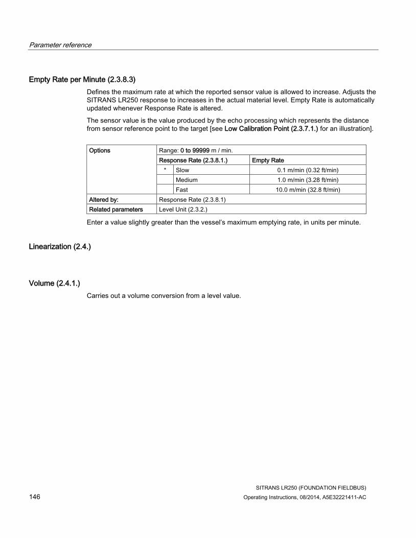
Parameter reference
SITRANS LR250 (FOUNDATION FIELDBUS)
146 Operating Instructions, 08/2014, A5E32221411-AC
Empty Rate per Minute (2.3.8.3)
Defines the maximum rate at which the reported sensor value is allowed to increase. Adjusts the SITRANS LR250 response to increases in the actual material level. Empty Rate is automatically updated whenever Response Rate is altered.
The sensor value is the value produced by the echo processing which represents the distance from sensor reference point to the target [see Low Calibration Point (2.3.7.1.) for an illustration].
Options Range: 0 to 99999 m / min.
Response Rate (2.3.8.1.) Empty Rate
* Slow 0.1 m/min (0.32 ft/min)
Medium 1.0 m/min (3.28 ft/min)
Fast 10.0 m/min (32.8 ft/min)
Altered by: Response Rate (2.3.8.1)
Related parameters Level Unit (2.3.2.)
Enter a value slightly greater than the vessel’s maximum emptying rate, in units per minute.
Linearization (2.4.)
Volume (2.4.1.)
Carries out a volume conversion from a level value.

Parameter reference
SITRANS LR250 (FOUNDATION FIELDBUS)
Operating Instructions, 08/2014, A5E32221411-AC 147
Vessel Shape (2.4.1.1.)
Defines the vessel shape and allows the LR250 to calculate volume instead of level. If None is selected, no volume conversion is performed. Select the vessel shape matching the monitored vessel or reservoir.
Vessel Shape LCD DISPLAY/ Description Also required
* None NONE/ No volume calculation required
N/A
CYLINDER/ Flat end horizontal cylinder
Maximum volume
SPHERE/ Sphere
Maximum volume
LINEAR/ Upright, linear (flat bottom)
Maximum volume
CONICAL BOT/ Conical or pyramidal bottom
Maximum volume, dimension A
PARABOLIC BOT/Parabolic bottom
Maximum volume, dimension A

Parameter reference
SITRANS LR250 (FOUNDATION FIELDBUS)
148 Operating Instructions, 08/2014, A5E32221411-AC
Vessel Shape LCD DISPLAY/ Description Also required
HALF SPHERE BOT/ Half-sphere bottom
Maximum volume, dimension A
FLAT SLOPED BOT/ Flat sloped bottom
Maximum volume, dimension A
PARABOLIC ENDS/ Parabolic end horizontal cylinder
Maximum volume, dimension A, dimension L
LINEAR TABLE a) / Linearization table (level/volume breakpoints)
Maximum volume, level breakpoints, volume breakpoints
a) Linearization Table must be selected in order for level/volume values [see XY index (2.4.1.5.)] to be transferred.
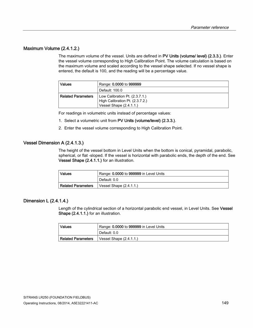
Parameter reference
SITRANS LR250 (FOUNDATION FIELDBUS)
Operating Instructions, 08/2014, A5E32221411-AC 149
Maximum Volume (2.4.1.2.)
The maximum volume of the vessel. Units are defined in PV Units (volume/ level) (2.3.3.). Enter the vessel volume corresponding to High Calibration Point. The volume calculation is based on the maximum volume and scaled according to the vessel shape selected. If no vessel shape is entered, the default is 100, and the reading will be a percentage value.
Values Range: 0.0000 to 999999
Default: 100.0
Related Parameters Low Calibration Pt. (2.3.7.1.) High Calibration Pt. (2.3.7.2.) Vessel Shape (2.4.1.1.)
For readings in volumetric units instead of percentage values:
1. Select a volumetric unit from PV Units (volume/level) (2.3.3.).
2. Enter the vessel volume corresponding to High Calibration Point.
Vessel Dimension A (2.4.1.3.)
The height of the vessel bottom in Level Units when the bottom is conical, pyramidal, parabolic, spherical, or flat -sloped. If the vessel is horizontal with parabolic ends, the depth of the end. See Vessel Shape (2.4.1.1.) for an illustration.
Values Range: 0.0000 to 999999 in Level Units
Default: 0.0
Related Parameters Vessel Shape (2.4.1.1.)
Dimension L (2.4.1.4.)
Length of the cylindrical section of a horizontal parabolic end vessel, in Level Units. See Vessel Shape (2.4.1.1.) for an illustration.
Values
Range: 0.0000 to 999999 in Level Units
Default: 0.0
Related Parameters Vessel Shape (2.4.1.1.)

Parameter reference
SITRANS LR250 (FOUNDATION FIELDBUS)
150 Operating Instructions, 08/2014, A5E32221411-AC
XY index (2.4.1.5.)
Level/Volume breakpoints allow you to define a complex vessel shape as a series of segments. A value is assigned to each level breakpoint and a corresponding value is assigned to each volume breakpoint.
Volume values are defined in volume units and can be percent or volumetric; level values are defined in level units, and can be percent or linear.
Level values Range: 0.0000 to 999999 (m, cm, mm, ft, in, %)
Default: 0.0
Volume values Range: 0.0000 to 999999 (% or volumetric units)
Default: 0.0
Enter up to 32 level breakpoints, where the corresponding volume is known. The values corresponding to 100% and 0% levels must be entered. The breakpoints can be ordered from top to bottom, or the reverse.
Example (values are for example purposes only)
Breakpoint Number Level value (m) Volume value (l)
1 0 0
2 5 500
3 9 3000
4 19.5 8000

Parameter reference
SITRANS LR250 (FOUNDATION FIELDBUS)
Operating Instructions, 08/2014, A5E32221411-AC 151
Entering breakpoints via the hand-held programmer:
1. The default for level values is percent: if you want to select units instead, navigate to Setup (2.) > Sensor (2.3.) > Level Unit (2.3.2.), and select the desired unit.
2. Navigate to Setup (2.) > Sensor (2.3.) > PV Units (volume/level) (2.3.3.), and select the desired volume units.
3. Go to XY index (2.4.1.5.) and enter the number of the breakpoint you wish to adjust: for example, for breakpoint 1 enter 1.
4. Go to X value (2.4.1.6.) and enter the level value for the breakpoint just identified.
5. Go to Y value (2.4.1.7.) and enter the volume value for the breakpoint just identified.
6. Repeat steps 3 to 5 until values have been entered for all required breakpoints.
X value (2.4.1.6.)
See XY Index (2.4.1.5.).
Y value (2.4.1.7.)
See XY Index (2.4.1.5.).
Entering breakpoints via AMS: See Linearization (LTB) (Page 93)
After completing the above steps you will need to configure AIFB 1 and/or AIFB 2. [See AIFB 1 (2.6.) and AIFB 2 (2.7.) for details.]
Signal Processing (2.5.)
In AMS Device Manager, see the General tab under Signal Processing (LTB) (Page 95).
Near Range (2.5.1.)
The range in front of the device (measured from the sensor reference point within which any echoes will be ignored. (This is sometimes referred to as "Blanking" or "Dead Zone".) The factory setting is 50 mm (2") past the end of the antenna, and the range is dependent on the antenna type and process connection. [See Threaded Horn Antenna with extension (Page 215) and Flanged Horn (Page 220) for antenna heights to sensor reference point.]
Values Range: 0 to 20 m (0 to 65.6 ft)
Default depends on antenna type and process connection.
Examples: 1.5" threaded horn 185.3 mm (7.3")
4" horn with stainless steel flange and 100 mm (4") extension
373.3 mm (14.7")
Related parameters Unit (2.2.1.)

Parameter reference
SITRANS LR250 (FOUNDATION FIELDBUS)
152 Operating Instructions, 08/2014, A5E32221411-AC
Far Range (2.5.2.)
Note
Far Range can extend beyond the bottom of the vessel.
Allows the material level to drop below Low Calibration Point without generating a Loss of Echo (LOE) state. See Low Calibration Pt. (2.3.7.1.) for an illustration.
Values Range: Min. = Low Calibration Pt.
Max. = 33 m (108.27 ft)
Default: Value for Low Calibration Pt. + 1 m (3.28 ft)
Related parameters Unit (2.3.1.)
CLEF (Constrained Leading Edge Fit) Range (2.5.7.4.) a)
a) The value set for Far Range becomes the CLEF Range maximum. If the value for Far Range is changed after a CLEF Range value is entered, CLEF Range is reset to its default (0.00 m).
Use this feature if the measured surface can drop below the Low calibration point in normal operation.
Propogation Factor (2.5.3.)
Note
• When operating in a stillpipe, values for CLEF Range (2.5.7.4.), and for the Propagation Factor, should be set according to the pipe size. See the table below.
• For reliable results the antenna size must be close to the pipe size.
Compensates for the change in microwave velocity due to propagation within a metal stillpipe instead of in free space.
Values Range: 0.3 to 1.0 depending on pipe size.
Default: 1.0000
Nominal Pipe Sizea) 40 mm (1.5") 50 mm (2") 80 mm (3") 100 mm (4")
Propagation Factor 0.9844 0.988 0.9935 0.9965
CLEF Range (2.5.7.4.) Low calibration point - 700 mm (2.29 ft)b)
Low calibration point - 700 mm (2.29 ft)b)
Low calibration point - 1000 mm (3.28 ft)b)
Low calibration point - 1000 mm (3.28 ft)b)
a) Since pipe dimensions may vary slightly, the propagation factor may also vary.
b) CLEF range covers the whole measurement range except first 700 or 1000 mm from unit reference point (see A in graphic below)

Parameter reference
SITRANS LR250 (FOUNDATION FIELDBUS)
Operating Instructions, 08/2014, A5E32221411-AC 153
① sensor reference point ③ low calibration point
② air gap ④ CLEF range 2.5.7.4.
A 700 or 1000 mm
Note
Flanged encapsulated antenna
For Flanged encapsulated antenna (7ML5432) match the process connection size to the pipe diameter whenever possible (for example, mount a DN80/3" flange on DN80/3" pipe).
Minimum Sensor Value (2.5.4.)
The minimum usable value for the measuring range, in units defined in Unit (2.3.1.). (Default = 0.0 m)
To view this parameter via AMS Device Manager see Range under Signal Processing (LTB) (Page 95).
Maximum Sensor Value (2.5.5.)
The maximum usable value for the measuring range, in units defined in Unit (2.3.1.). (Default = 33.0 m)
To view this parameter via AMS Device Manager see Range under Signal Processing (LTB) (Page 95).

Parameter reference
SITRANS LR250 (FOUNDATION FIELDBUS)
154 Operating Instructions, 08/2014, A5E32221411-AC
Shots (2.5.6.)
The number of echo profile samples averaged to produce a measurement.
Values Range: 1 to 25
Default: 25 a)
a) To meet accuracy specification, the number of shots must be set to 25 [see Performance (Page 207)].
Echo Select (2.5.7.)
Algorithm (2.5.7.1.)
Selects the algorithm to be applied to the echo profile to extract the true echo.
Options * tF True First echo
F First echo
L Largest echo
BLF Best of Largest and First echo
Position Detect (2.5.7.2.)
Defines where on the echo the distance measurement is determined.
Options Center
* Hybrid (Center and CLEF)
CLEF (Constrained Leading Edge Fit)
Related parameters CLEF Range (2.5.7.4.)
If the vessel bottom is being reported as the level instead of the actual material level (at low level conditions), or if the dielectric constant of the liquid to be monitored is less than 3, we recommend setting Position Detect to Hybrid and CLEF (Constrained Leading Edge Fit) Range (2.5.7.4.) to 0.5 m (1.64 ft).

Parameter reference
SITRANS LR250 (FOUNDATION FIELDBUS)
Operating Instructions, 08/2014, A5E32221411-AC 155
Echo Threshold (2.5.7.3.)
Sets the minimum echo confidence that the echo must meet in order to prevent a Loss of Echo condition and the expiration of the Fail-safe (LOE) timer. When Confidence (2.5.9.1.) exceeds Echo Threshold (2.5.7.3.), the echo is accepted as a valid echo and is evaluated.
Values Range: 0 to 99
Default: 5
Related Parameters Loss of Echo (LOE) Timer (2.3.6.) Confidence (2.5.9.1.)
Use this feature when an incorrect material level is reported.
CLEF Range (2.5.7.4.)
Note
CLEF Range is referenced from Low Calibration Point (process empty level).
The CLEF algorithm is used mainly to allow correct level reporting for low dK materials which may otherwise cause an incorrect reading in an empty or almost empty vessel.
It is used from Low Calibration Point (process empty level ) up to the level defined by CLEF Range (see illustration below). Above that point the Center algorithm is used. For more detail see CLEF Range (Page 264).
Values Range: 0 to 20 m (0 to 65.6 ft)
Default: 0.0 m
Related parameters Position Detect (2.5.7.2.)
① CLEF Range
② Sensor reference point
③ Low calibration point (process empty level)
In applications with low dK materials we recommend setting CLEF Range to 0.5 m (1.64 ft) and Position Detect (2.5.7.2.) to Hybrid.

Parameter reference
SITRANS LR250 (FOUNDATION FIELDBUS)
156 Operating Instructions, 08/2014, A5E32221411-AC
Sampling (2.5.8.)
Provides a method of checking the reliability of a new echo before accepting it as the valid reading, based on numbers of samples above or below the currently selected echo.
Echo Lock (2.5.8.1.)
Note
Ensure the agitator is always running while SITRANS LR250 is monitoring the vessel, to avoid stationary blade detection.
Selects the measurement verification process. See Echo Lock (2.5.8.1.) for more details.
Options Lock Off (no verification)
Maximum Verification
* Material Agitator
Total Lock
Related parameters Fill Rate per Minute (2.3.8.2.) Empty Rate per Minute (2.3.8.3.) Up Sampling (2.5.8.2.) Down Sampling (2.5.8.3.)
For radar applications, Material Agitator is the most often-used setting, to avoid agitator blade detection.
Sampling Up (2.5.8.2.)
Specifies the number of consecutive echoes that must appear above the echo currently selected, before the measurement is accepted as valid.
Values Range: 1 to 50
Default: 5
Down Sampling (2.5.8.3.)
Specifies the number of consecutive echoes that must appear below the echo currently selected, before the measurement is accepted as valid.
Values Range: 1 to 50
Default: 2 (see Related parameters)
Related parameters
Echo Lock (2.5.8.1.) If Echo Lock set to any value other than its default (2), then Down Sampling default = 5.

Parameter reference
SITRANS LR250 (FOUNDATION FIELDBUS)
Operating Instructions, 08/2014, A5E32221411-AC 157
Echo Quality (2.5.9.)
Confidence (2.5.9.1.)
Indicates echo reliability: higher values represent better echo quality. The display shows the echo confidence of the last measurement. Echo Threshold (2.5.7.3.) defines the minimum criterion for echo confidence.
Values (view only)
0 to 99
Echo Threshold (2.5.7.3.)
Related Parameters
Open the menu Device – Echo Profile Utilities and click on the tab Echo Profile.
Echo Strength (2.5.9.2.)
Displays the absolute strength (in dB above 1 μV rms) of the echo selected as the measurement echo.
Values (view only)
Range: –20 to 99
TVT (Auto False Echo Suppression) Setup (2.5.10.)
Note
• Make sure material level is below all known obstructions when Auto False Echo Suppression is used to learn the echo profile. (An empty or almost empty vessel is recommended.)
• Note the distance to material level when Auto False Echo learns the environment. Set Auto False Echo Suppression Range to a shorter distance to avoid the material echo being screened out.
• Set Auto False Echo Suppression and Auto False Echo Suppression Range during startup, if possible.
• If the vessel contains an agitator it should be running.
• Before adjusting these parameters, rotate the instrument for best signal (lower false-echo amplitude).

Parameter reference
SITRANS LR250 (FOUNDATION FIELDBUS)
158 Operating Instructions, 08/2014, A5E32221411-AC
Auto False Echo Suppression (2.5.10.1.)
Used together with Auto False Echo Suppression Range (2.5.10.2.) to screen out false echoes in a vessel with known obstructions. A ’learned TVT’ (time varying threshold) replaces the default TVT over a specified range. See Auto False Echo Suppression (Page 265) for a more detailed explanation.
Before Auto False Echo Suppression
① TVT Hover Level ④ echo marker
② default TVT ⑤ material level
③ false echo
1. Determine Auto False Echo Suppression Range. Measure the actual distance from the sensor reference point to the material surface using a rope or tape measure.
2. Subtract 0.5 m (20") from this distance, and use the resulting value.
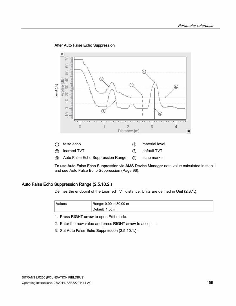
Parameter reference
SITRANS LR250 (FOUNDATION FIELDBUS)
Operating Instructions, 08/2014, A5E32221411-AC 159
After Auto False Echo Suppression
① false echo ④ material level
② learned TVT ⑤ default TVT
③ Auto False Echo Suppression Range ⑥ echo marker
To use Auto False Echo Suppression via AMS Device Manager note value calculated in step 1 and see Auto False Echo Suppression (Page 96).
Auto False Echo Suppression Range (2.5.10.2.)
Defines the endpoint of the Learned TVT distance. Units are defined in Unit (2.3.1.).
Values Range: 0.00 to 30.00 m
Default: 1.00 m
1. Press RIGHT arrow to open Edit mode.
2. Enter the new value and press RIGHT arrow to accept it.
3. Set Auto False Echo Suppression (2.5.10.1.).

Parameter reference
SITRANS LR250 (FOUNDATION FIELDBUS)
160 Operating Instructions, 08/2014, A5E32221411-AC
Hover Level (2.5.10.3.)
Defines how high the TVT (Time Varying Threshold) is placed above the noise floor of the echo profile, as a percentage of the difference between the peak of the largest echo in the profile and the noise floor. See Auto False Echo Suppression (2.5.10.1) for an illustration.
Values Range: 0 to 100%
Default: 40%
When the device is located in the center of the vessel, the TVT hover level may be lowered to increase the confidence level of the largest echo.
Shaper Mode (2.5.10.4.)
Enables/disables TVT shaper (2.5.11.)
Options ON
* OFF
TVT Shaper (2.5.11.)
Note
• The range is –100 to +100 bits. With 2 bits per dB this gives a range of –50 to +50 dB.
• Shaper Mode (2.5.10.4.) must be turned ON in order for TVT shaper points to be transferred.
Adjusts the TVT (Time Varying Threshold) at a specified range (breakpoint on the TVT). This allows you to reshape the TVT to avoid unwanted echoes. There are 40 breakpoints arranged in 5 groups. (We recommend using SIMATIC PDM to access this feature.)
To use TVT shaper via LUI (local user interface):
1. Go to Shaper Mode (2.5.10.4.) and select On.
2. In TVT shaper, go to Breakpoint 1-9 (2.5.11.1.).
3. Open Breakpoint 1 and enter the TVT Offset value (between –50 and 50).
4. Go to the next Breakpoint and repeat step 3 until all desired breakpoint values have been entered.

Parameter reference
SITRANS LR250 (FOUNDATION FIELDBUS)
Operating Instructions, 08/2014, A5E32221411-AC 161
Breakpoint 1-9 (2.5.11.1.)
Values Range: –100 to +100 bits (equivalent to – 50 to +50 dB)
Default: 0 dB
Breakpoint 10-18 (2.5.11.2.)
Values Range: –100 to +100 bits (equivalent to – 50 to +50 dB)
Default: 0 dB
Breakpoint 19-27 (2.5.11.3.)
Values Range: –100 to +100 bits (equivalent to – 50 to +50 dB)
Default: 0 dB
Breakpoint 28-36 (2.5.11.4.)
Values Range: –100 to +100 bits (equivalent to – 50 to +50 dB)
Default: 0 dB
Breakpoint 37-40 (2.5.11.5.)
Values Range: –100 to +100 bits (equivalent to – 50 to +50 dB)
Default: 0 dB
To access TVT Shaper via AMS Device Manager see TVT Shaper (Page 96).

Parameter reference
SITRANS LR250 (FOUNDATION FIELDBUS)
162 Operating Instructions, 08/2014, A5E32221411-AC
AIFB1 (2.6.)
Note
• Default settings in the parameter tables are indicated with an asterisk (*) unless explicitly stated.
• All AIFB parameters are read only via LUI and AMS Device Manager, and can only be changed using a remote host such as DeltaV or NI-FBUS Configurator.
• AIFB 1 and AIFB 2 are not active out of the box. These blocks will show Out of Service on the LCD at startup. If these blocks are needed for an FF application, use a tool such as DeltaV or NI-FBUS Configurator to configure and schedule the blocks. See Configuration in manual Foundation Fieldbus for Level Instruments (7ML19985MP01) for further details.
Static Revision Number (2.6.1.)
The revision level of the static data associated with Analog Input Function Block 1. The Static Revision No. is updated whenever a configuration parameter is changed.
Mode (2.6.2.)
Used to request an operating mode from the Analog Input Function Block.
Options Auto Mode (AUTO)
Manual Mode (MAN)
Out of Service (OOS)
Allows you to put the SITRANS LR250 into Out of Service Mode and then reset it to Auto Mode. Manual Mode can be used when simulating output. See Simulation in manual Foundation Fieldbus for Level Instruments (7ML19985MP01) for more details.
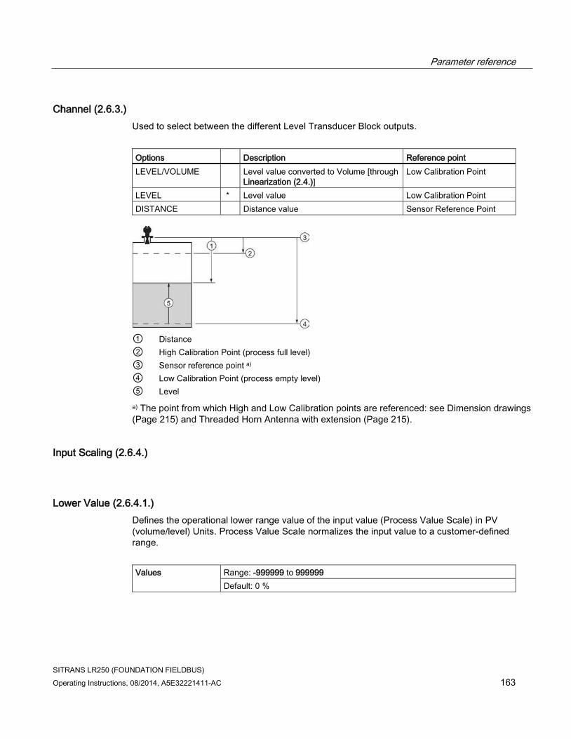
Parameter reference
SITRANS LR250 (FOUNDATION FIELDBUS)
Operating Instructions, 08/2014, A5E32221411-AC 163
Channel (2.6.3.)
Used to select between the different Level Transducer Block outputs.
Options Description Reference point
LEVEL/VOLUME Level value converted to Volume [through Linearization (2.4.)]
Low Calibration Point
LEVEL * Level value Low Calibration Point
DISTANCE Distance value Sensor Reference Point
① Distance
② High Calibration Point (process full level)
③ Sensor reference point a)
④ Low Calibration Point (process empty level)
⑤ Level
a) The point from which High and Low Calibration points are referenced: see Dimension drawings (Page 215) and Threaded Horn Antenna with extension (Page 215).
Input Scaling (2.6.4.)
Lower Value (2.6.4.1.)
Defines the operational lower range value of the input value (Process Value Scale) in PV (volume/level) Units. Process Value Scale normalizes the input value to a customer-defined range.
Values Range: -999999 to 999999
Default: 0 %
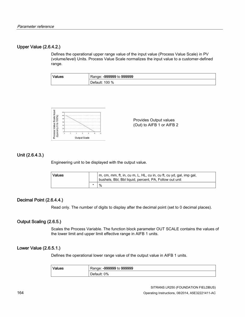
Parameter reference
SITRANS LR250 (FOUNDATION FIELDBUS)
164 Operating Instructions, 08/2014, A5E32221411-AC
Upper Value (2.6.4.2.)
Defines the operational upper range value of the input value (Process Value Scale) in PV (volume/level) Units. Process Value Scale normalizes the input value to a customer-defined range.
Values Range: -999999 to 999999
Default: 100 %
Provides Output values (Out) to AIFB 1 or AIFB 2
Unit (2.6.4.3.)
Engineering unit to be displayed with the output value.
Values m, cm, mm, ft, in, cu m, L, HL, cu in, cu ft, cu yd, gal, imp gal, bushels, Bbl, Bbl liquid, percent, PA, Follow out unit
* %
Decimal Point (2.6.4.4.)
Read only. The number of digits to display after the decimal point (set to 0 decimal places).
Output Scaling (2.6.5.)
Scales the Process Variable. The function block parameter OUT SCALE contains the values of the lower limit and upper limit effective range in AIFB 1 units.
Lower Value (2.6.5.1.)
Defines the operational lower range value of the output value in AIFB 1 units.
Values Range: -999999 to 999999
Default: 0%

Parameter reference
SITRANS LR250 (FOUNDATION FIELDBUS)
Operating Instructions, 08/2014, A5E32221411-AC 165
Upper Value (2.6.5.2.)
Defines the operational upper range value of the output value in AIFB1 units.
Values Range: -999999 to 999999
Default: 100%
Unit (2.6.5.3.)
Engineering unit to be displayed with the output value.
Values m, cm, mm, ft, in, cu m, L, HL, cu in, cu ft, cu yd, gal, imp gal, bushels, Bbl, Bbl liquid, percent, PA, Follow out unit
* %
Decimal Point (2.6.5.4.)
Read only. The number of digits to display after the decimal point (set to two decimal places).
Alarms and Warnings (2.6.6.)
High Limit Alarm (2.6.6.1.)
The setting for the upper alarm limit in AIFB1 units.
Values Range: -Infinity to Infinity
Default: Inf
High Limit Warning (2.6.6.2.)
The setting for the upper warning limit in AIFB1 units.
Values Range: -Infinity to Infinity
Default: Inf

Parameter reference
SITRANS LR250 (FOUNDATION FIELDBUS)
166 Operating Instructions, 08/2014, A5E32221411-AC
Low Limit Warning (2.6.6.3.)
The setting for the lower warning limit in AIFB1 units.
Values Range: -Infinity to Infinity
Default: -Inf
Low Limit Alarm (2.6.6.4.)
The setting for the lower alarm limit in AIFB1 units.
Values Range: -Infinity to Infinity
Default: -Inf
Limit Hysteresis (2.6.6.5.)
Hysteresis is used to adjust the sensitivity of the trigger for alarm messages. It is used to compensate when a process variable fluctuates around the same value as a limit. A high level alarm occurs when a value exceeds an upper limit. The alarm’s status remains true until the value drops below the limit minus the alarm hysteresis. The directions are reversed for low limit detection.
Values Range: 0 to 50
Default: 0.50
Enter a value for the hysteresis here, to be used for all warnings and alarms. The units are the same as the Output scale, i.e. AIFB1 units.
Display (2.6.7.)
Filter Time Constant (2.6.7.1.)
The time constant for the damping filter. The damping filter smooths out the response to a sudden change in level. This is an exponential filter and the engineering unit is always in seconds. See Damping (Page 268) for more detail.
Values Range: 0 to 600 s
Default: 0 a)
a) To meet accuracy specification, Filter Time Constant (PV_FTIME) must be changed from default of 0.0 s to a minimum of 10.0 seconds [see Performance (Page 207)].

Parameter reference
SITRANS LR250 (FOUNDATION FIELDBUS)
Operating Instructions, 08/2014, A5E32221411-AC 167
AIFB 2 (2.7.)
See AIFB1 (2.6.): the parameters for AIFB 2 are identical to AIFB 1.
Measured Values (2.8.)
(for diagnostic purposes)
Read only. Allows you to view measured values for diagnostic purposes.
Main Output (PV - Primary Value) (2.8.1.)
The value for level, or volume (if volume conversion is selected).
In AMS Device Manager, see Process Variables Level Transducer Block-LTB (Page 123).
Output, no linearization (SV1 - Secondary Value 1) (2.8.2.)
The value for level.
Output, no level offset (SV2 - Secondary Value 2) (2.8.3.)
The value for distance.
Diagnostics (3.)
Echo Profile (3.1.)
Allows you to request the current echo profile via the handheld programmer, or via AMS Device Manager. For more detail see Echo Processing (Page 260).
To request a profile via AMS Device Manager:
See Echo Profile (Page 99).
To request a profile via the handheld programmer:
1. Navigate to Level Meter > Diagnostics (3.) > Echo Profile (3.1.).
2. Press RIGHT arrow to request a profile. [See Requesting an Echo Profile (Page 67) for more details.]

Parameter reference
SITRANS LR250 (FOUNDATION FIELDBUS)
168 Operating Instructions, 08/2014, A5E32221411-AC
Fault Reset (3.2.)
Clears faults (see chart below).
Clearing a fault in one parameter of a ’maintenance pair’, automatically clears a fault in the second parameter of the pair. For example, entering S3 or S4 will clear a fault on Device Lifetime Reminder 1 (Maintenance Required), and on Device Lifetime Reminder 2 (Maintenance Demanded). This applies when clearing faults via the handheld programmer, or the 375 Field Communicator.
Fault code Description
S3 Device Lifetime Reminder 1 (Maintenance Required)
S4 Device Lifetime Reminder 2 (Maintenance Demanded)
S6 Sensor Lifetime Reminder 1 (Maintenance Required)
S7 Sensor Lifetime Reminder 2 (Maintenance Demanded)
S8 Device Service Reminder 1 (Maintenance Required)
S9 Device Service Reminder 2 (Maintenance Demanded)
S12 Internal Temperature High
S17 Calibration Schedule Reminder 1 (Maintenance Required)
S18 Calibration Schedule Reminder 2 (Maintenance Demanded)
To clear a fault using the handheld programmer:
● Enter the fault code number then press RIGHT arrow .
Electronics Temperature (3.3.)
To access the following parameters via AMS Device Manager see Electronics Temperature under Maintenance & Diagnostics (LTB) (Page 100).
Minimum Value (3.3.1.)
The minimum recorded internal electronics temperature, reported in units defined in Temperature Units (2.3.4.).
Maximum Value (3.3.2.)
The maximum recorded internal electronics temperature, reported in units defined in Temperature Units (2.3.4.).

Parameter reference
SITRANS LR250 (FOUNDATION FIELDBUS)
Operating Instructions, 08/2014, A5E32221411-AC 169
Peak Values (3.4.)
Minimum Measured Value (3.4.1.)
The minimum recorded Sensor value, reported in units defined in Unit (2.3.1.).
Maximum Measured Value (3.4.2.)
The maximum recorded Sensor value, reported in units defined in Unit (2.3.1.).
Service (4.)
Note
Default settings in the parameter tables are indicated with an asterisk (*) unless explicitly stated.
Parameter reference
SITRANS LR250 (FOUNDATION FIELDBUS)
170 Operating Instructions, 08/2014, A5E32221411-AC
Master Reset (4.1.)
Note
• The following parameters are not reset by any reset type: Write Protection, PIN to Unlock, Auto False Echo Suppression Range, Learned TVT.
• While an FF Object Dictionary Reset is in progress, do not perform an action using the local display interface until the reset is complete. This could cause a temporary loss of communications.
Reset Type Result
Factory Defaults a) Default. Resets all user parameters to the manufacturer’s default settings. Following this type of reset, complete reprogramming is required.
Standard Defaults Resets all parameters to standard default settings.
Informational Resets parameters such as Block Descriptor, Strategy, Device Install Date, Device Message.
Functional a) Resets parameters that control device behavior and functionality (such as Low Calibration Point).
Warm Start Has the same effect as recycling power to the device.
FF Object Dictionary Resets the FF standard block profile parameters (such as block tags) to their specified defaults. This option also clears any function block parameters and device schedule b) set by the user.
a) The only difference between Factory Defaults and Functional reset is that Factory Defaults resets maintenance parameters, such as device and sensor wear, calibration and maintenance timers. Functional reset does not reset these parameters.
b) See Data transmission in manual Foundation Fieldbus for Level Instruments (7ML19985MP01) for further details.
To access via AMS Device Manager see Master Reset under Operation (RESOURCE) (Page 108).
To perform a reset via the handheld programmer:
1. Press RIGHT arrow to open Edit Mode then scroll down to the desired reset type and
press RIGHT arrow to select it.
2. Press LEFT arrow to exit.
After performing a master reset, the device will stop measuring, the Resource and Level Transducer Blocks will go to Out of Service, and the LUI will show the Quick Start Wizard until the device is configured.

Parameter reference
SITRANS LR250 (FOUNDATION FIELDBUS)
Operating Instructions, 08/2014, A5E32221411-AC 171
Remaining Device Lifetime (4.2.)
Note
• Default settings in the parameter tables are indicated with an asterisk (*) unless explicitly stated.
• Four sets of parameters allow you to monitor the Device/Sensor Lifetimes and set up Maintenance/Service schedules, based on operating hours instead of a calendar-based schedule. See also Remaining Sensor Lifetime (4.3.), Service Schedule (4.4.), and Calibration Schedule (4.5.).
• Performing a reset to Factory Defaults will reset all the Maintenance Schedule parameters to their factory defaults.
• The device operates in years. To view Remaining Device Lifetime parameters in hours (via AMS Device Manager only) see Remaining Device Lifetime under Maintenance & Diagnostics (RESOURCE) (Page 111).
The device tracks itself based on operating hours and monitors its predicted lifetime. You can modify the expected device lifetime, set up schedules for maintenance alerts, and acknowledge them.
The maintenance warnings and alarms are communicated to the end user through status information. This information can be integrated into any Asset Management system.
To access these parameters via AMS Device Manager see Remaining Device Lifetime under Maintenance & Diagnostics (RESOURCE) (Page 111).
Time in operation (4.2.2.)
Read only. The amount of time the device has been operating.
Remaining lifetime (4.2.3.)
Read only. LIfetime (Expected) (4.2.1.) less Time in Operation (4.2.2.).
Activation of Reminders (4.2.4.)
Allows you to enable a maintenance reminder.
Options REMinder 1 (Maintenance REQuired)
REMinder 2 (Maintenance DEManded)
REMinders 1 AND 2 (Maintenance Required and Maintenance Demanded)
* OFF
1. First set the reminder values in Reminder 1 before Lifetime (Required) (4.2.5.)/Reminder 2 before Lifetime (Demanded) (4.2.6.).
2. Select the desired Activation of Reminders option.

Parameter reference
SITRANS LR250 (FOUNDATION FIELDBUS)
172 Operating Instructions, 08/2014, A5E32221411-AC
Reminder 1 before Lifetime (Required) (4.2.5.)
If Remaining Lifetime (4.2.3.) is equal to or less than this value, the device generates a Maintenance Required reminder.
Values Range: 0 to 20 years
Default: 0.164 years
1. Modify limit values as required.
2. Set Activation of Reminders (4.2.4.) to the desired option.
Reminder 2 before Lifetime (Demanded) (4.2.6.)
If Remaining Lifetime (4.2.3.) is equal to or less than this value, the device generates a Maintenance Demanded reminder.
Values Range: 0 to 20 years
Default: 0.019 years
1. Modify values as required.
2. Set Activation of Reminders (4.2.4.) to the desired option.
Maintenance Status (4.2.7.)
Indicates which level of maintenance reminder is active.
To display the level of maintenance reminder that is active in AMS Device Manager see Extended Diagnostics under Device Diagnostics [Resource Block - RESOURCE (Page 119)].
Acknowledge Status (4.2.8.)
Indicates which level of maintenance reminder has been acknowledged.
Acknowledge (4.2.9.)
Acknowledges the current maintenance reminder.
To acknowledge a reminder via the handheld programmer:
1. Press RIGHT arrow twice to open parameter view and activate Edit Mode.
2. Press RIGHT arrow to acknowledge the reminder.

Parameter reference
SITRANS LR250 (FOUNDATION FIELDBUS)
Operating Instructions, 08/2014, A5E32221411-AC 173
Remaining Sensor Lifetime (4.3.)
Note
• Default settings in the parameter tables are indicated with an asterisk (*) unless explicitly stated.
• Four sets of parameters allow you to monitor the Device/Sensor Lifetimes and set up Maintenance/Service schedules, based on operating hours instead of a calendar-based schedule. See also Remaining Device Lifetime (4.2.), Service Schedule (4.4.), and Calibration Schedule (4.5.).
• Performing a reset to Factory Defaults will reset all the Maintenance Schedule parameters to their factory defaults.
• The device operates in years. To view Remaining Sensor Lifetime parameters in hours (via AMS Device Manager only) see Remaining Sensor Lifetime in Maintenance & Diagnostics (LTB) (Page 100).
The device monitors the predicted lifetime of the sensor (the components exposed to the vessel environment). You can modify the expected sensor lifetime, set up schedules for maintenance reminders, and acknowledge them.
To access these parameters via AMS Device Manager see Remaining Sensor Lifetime in Maintenance & Diagnostics (LTB) (Page 100).
Lifetime (expected) (4.3.1.)
Allows you to override the factory default.
Values
Units: years
Range: 0 to 20 years
Default: 10.00 years
Time in Operation (4.3.2.)
The amount of time the sensor has been operating. Can be reset to zero after performing a service or replacing the sensor.
To reset to zero:
● Via the handheld programmer, manually reset Time in Operation (4.3.2.) to zero.
Remaining Lifetime (4.3.3.)
Read only. Lifetime (expected) (4.3.1.) less Time in Operation (4.3.2.).

Parameter reference
SITRANS LR250 (FOUNDATION FIELDBUS)
174 Operating Instructions, 08/2014, A5E32221411-AC
Activation of Reminders (4.3.4.)
Allows you to enable a maintenance reminder.
Options
REMinder 1 (Maintenance Required)
REMinder 2 (Maintenance Demanded)
REMinders 1 and 2 (Maintenance Required and Maintenance Demanded)
* OFF
1. First set the values in Reminder 1 before Lifetime (Required) (4.3.5.)/Reminder 2 before Lifetime(Demanded) (4.3.6.).
2. Select the desired Activation of Reminders option.
Reminder 1 before Lifetime (Required) (4.3.5.)
If Remaining Lifetime (4.3.3.) is equal to or less than this value, the device generates a Maintenance Required reminder.
Values Range: 0 to 20 years
Default: 0.164 years
1. Modify limit values as required.
2. Set Activation of Reminders (4.3.4.) to the desired option.
Reminder 2 before Lifetime (Demanded) (4.3.6.)
If Remaining Lifetime (4.3.3.) is equal to or less than this value, the device generates a Maintenance Demanded reminder.
Values Range: 0 to 20 years
Default: 0.019 years
1. Modify limit values as required.
2. Set Activation of Reminders (4.3.4.) to the desired option.
Maintenance Status (4.3.7.)
Indicates which level of maintenance reminder is active.
To display the level of maintenance reminder in AMS Device Manager see Extended Diagnostics under Device Diagnostics (Level Transducer Block - LTB) (Page 114).
Parameter reference
SITRANS LR250 (FOUNDATION FIELDBUS)
Operating Instructions, 08/2014, A5E32221411-AC 175
Acknowledge Status (4.3.8.)
Indicates which level of maintenance reminder has been acknowledged.
Acknowledge (4.3.9.)
Acknowledges the current maintenance reminder.
To acknowledge a reminder via the handheld programmer:
1. Press RIGHT arrow twice to open parameter view and activate Edit Mode.
2. Press RIGHT arrow to acknowledge the reminder.
Service Schedule (4.4.)
Note
• Default settings in the parameter tables are indicated with an asterisk (*) unless explicitly stated.
• Four sets of parameters allow you to monitor the Device/Sensor Lifetimes and set up Maintenance/Service schedules, based on operating hours instead of a calendar-based schedule. See also Remaining Device Lifetime (4.2.), Remaining Sensor Lifetime (4.3.), and Calibration Schedule (4.5.).
• Performing a reset to Factory Defaults will reset all the Maintenance Schedule parameters to their factory defaults.
• The device operates in years. To view Service Interval parameters in hours or days (via AMS Device Manager only) see Service Schedule (4.4.1.).
The device tracks service intervals based on operating hours and monitors the predicted lifetime to the next service. You can modify the Total Service Interval, set schedules for maintenance reminders, and acknowledge them.
The maintenance warnings and alarms are communicated to the end user through status information. This information can be integrated into any Asset Management system.
To access these parameters via AMS Device Manager see Service Schedule under Maintenance & Diagnostics (LTB) (Page 100).
Service Interval (4.4.1.)
User-configurable recommended time between product inspections.
Values Units: years
Range: 0 to 20 years
Default: 1.0 year

Parameter reference
SITRANS LR250 (FOUNDATION FIELDBUS)
176 Operating Instructions, 08/2014, A5E32221411-AC
Time Since Last Service (4.4.2.)
Time elapsed since last service. Can be reset to zero after performing a service.
To reset to zero:
● Via the handheld programmer, manually reset Time Since Last Service (4.4.2.) to zero.
Time Until Next Service (4.4.3.)
Read only. Service Interval (4.4.1.) less Time Since Last Service (4.4.2.).
Activation of Reminders (4.4.4.)
Allows you to enable a maintenance reminder.
Options * Timer OFF
ON NO LIMITS
ON - REMinder 1 (Maintenance Required) checked
ON - REMinders 1 and 2 checked
ON - REMinder 2 (Maintenance Demanded) checked
1. First set the values in Reminder 1 before Service (Required) (4.4.5.)/Reminder 2 before Service (Demanded) (4.4.6.).
2. Select the desired Activation of Reminders option.
Reminder 1 before Service (Required) (4.4.5.)
If Time Until Next Service (4.4.3.) is equal to or less than this value, the device generates a Maintenance Required reminder.
Values Range: 0 to 20 years
Default: 0.164 years
1. Modify limit values as required.
2. Set Activation of Reminders (4.4.4.) to the desired option.
Parameter reference
SITRANS LR250 (FOUNDATION FIELDBUS)
Operating Instructions, 08/2014, A5E32221411-AC 177
Reminder 2 before Service (Demanded) (4.4.6.)
If Time Until Next Service (4.4.3.) is equal to or less than this value, the device generates a Maintenance Demanded reminder.
Values Range: 0 to 20 years
Default: 0.019 years
1. Modify values as required
2. Set Activation of Reminders (4.4.4.) to the desired option.
Maintenance Status (4.4.7.)
Indicates which level of maintenance reminder is active.
To display the level of maintenance reminder in AMS Device Manager see Extended Diagnostics under Device Diagnostics (Level Transducer Block - LTB) (Page 114).
Acknowledge Status (4.4.8.)
Indicates which level of maintenance reminder has been acknowledged.
Acknowledge (4.4.9.)
Acknowledges the current maintenance reminder.
To acknowledge a reminder via the handheld programmer:
1. Press RIGHT arrow twice to open parameter view and activate Edit Mode.
2. Press RIGHT arrow to acknowledge the reminder.

Parameter reference
SITRANS LR250 (FOUNDATION FIELDBUS)
178 Operating Instructions, 08/2014, A5E32221411-AC
Calibration Schedule (4.5.)
Note
• Default settings in the parameter tables are indicated with an asterisk (*) unless explicitly stated.
• Four sets of parameters allow you to monitor the Device/Sensor Lifetimes and set up Maintenance/Service schedules, based on operating hours instead of a calendar-based schedule. See also Remaining Device Lifetime (4.2.), Remaining Sensor Lifetime (4.3.), and Service Schedule (4.4.).
• Performing a reset to Factory Defaults will reset all the Maintenance Schedule parameters to their factory defaults.
• The device operates in years. To view Calibration Interval parameters in hours (via AMS Device Manager only) see Calibration Schedule under Maintenance & Diagnostics (RESOURCE) (Page 111).
The device tracks calibration intervals based on operating hours and monitors the predicted lifetime to the next calibration. You can modify the Total Calibration Interval, set schedules for maintenance reminders, and acknowledge them.
To access these parameters via AMS Device Manager see Calibration Schedule under Maintenance & Diagnostics (RESOURCE) (Page 111).
Calibration Interval (4.5.1.)
User-configurable recommended time between product calibrations.
Values Units: years
Range: 0 to 20 years
Default: 1.0 year
Time Since Last Calibration (4.5.2.)
Time elapsed since last calibration. Can be reset to zero after performing a calibration.
To reset to zero:
● Via the handheld programmer, manually reset Time Since Last Calibration (4.5.2.) to zero.
Time Until Next Calibration (4.5.3.)
Read only. Calibration Interval (4.5.1.) less Time Since Last Calibration (4.5.2.).

Parameter reference
SITRANS LR250 (FOUNDATION FIELDBUS)
Operating Instructions, 08/2014, A5E32221411-AC 179
Activation of Reminders (4.5.4.)
Allows you to enable a maintenance reminder.
Options * Timer OFF
ON NO LIMITS
ON - REMinder 1 (Maintenance Required) checked
ON - REMinders 1 and 2 checked
ON—REMinder 2 (Maintenance Demanded) checked
1. First set the limit values in Reminder 1 before Calibration (Required) (4.5.5.)/Reminder 2 before Calibration (Demanded) (4.5.6.).
2. Select the desired Activation of Reminders option.
Reminder 1 before Calibration (Required) (4.5.5.)
If Time Until Next Calibration (4.5.3.) is equal to or less than this value, the device generates a Maintenance Required reminder.
Values Range: 0 to 20 years
Default: 0.164 years
1. Modify limit values as required.
2. Set Activation of Reminders (4.5.4.) to the desired option.
Reminder 2 before Calibration (Demanded) (4.5.6.)
If Time Until Next Calibration (4.5.3.) is equal to or less than this value, the device generates a Maintenance Demanded reminder.
Values Range: 0 to 20 years
Default: 0.019 years
1. Modify limit values as required.
2. Set Activation of Reminders (4.5.4.) to the desired option.
Maintenance Status (4.5.7.)
Indicates which level of maintenance reminder is active.
To display the level of maintenance reminder that is active in AMS Device Manager see Extended Diagnostics under Device Diagnostics (Resource Block - RESOURCE) (Page 119).
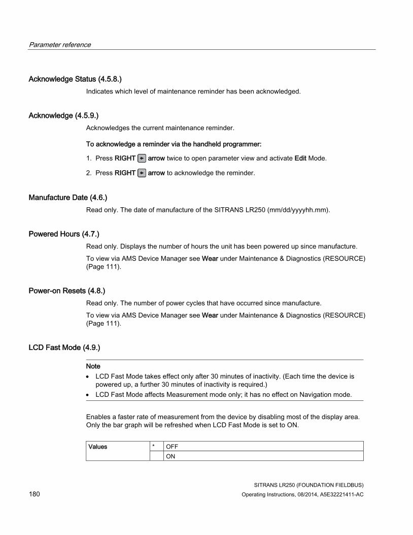
Parameter reference
SITRANS LR250 (FOUNDATION FIELDBUS)
180 Operating Instructions, 08/2014, A5E32221411-AC
Acknowledge Status (4.5.8.)
Indicates which level of maintenance reminder has been acknowledged.
Acknowledge (4.5.9.)
Acknowledges the current maintenance reminder.
To acknowledge a reminder via the handheld programmer:
1. Press RIGHT arrow twice to open parameter view and activate Edit Mode.
2. Press RIGHT arrow to acknowledge the reminder.
Manufacture Date (4.6.)
Read only. The date of manufacture of the SITRANS LR250 (mm/dd/yyyyhh.mm).
Powered Hours (4.7.)
Read only. Displays the number of hours the unit has been powered up since manufacture.
To view via AMS Device Manager see Wear under Maintenance & Diagnostics (RESOURCE) (Page 111).
Power-on Resets (4.8.)
Read only. The number of power cycles that have occurred since manufacture.
To view via AMS Device Manager see Wear under Maintenance & Diagnostics (RESOURCE) (Page 111).
LCD Fast Mode (4.9.)
Note
• LCD Fast Mode takes effect only after 30 minutes of inactivity. (Each time the device is powered up, a further 30 minutes of inactivity is required.)
• LCD Fast Mode affects Measurement mode only; it has no effect on Navigation mode.
Enables a faster rate of measurement from the device by disabling most of the display area. Only the bar graph will be refreshed when LCD Fast Mode is set to ON.
Values * OFF
ON

Parameter reference
SITRANS LR250 (FOUNDATION FIELDBUS)
Operating Instructions, 08/2014, A5E32221411-AC 181
LCD Contrast (4.10.)
The factory setting is for optimum visibility at room temperature and in average light conditions. Extremes of temperature will lessen the contrast.
Values Range: 0 (High contrast) to 20 (Low contrast). Default: 10
Adjust the value to improve visibility at room temperature and in average light conditions. Change the value in small steps to ensure you can continue to read the display.
Secondary Value (4.11.)
Use the secondary value to capture the menu navigation path to any viewable parameter. Once the navigation path is stored, the value of that parameter will be displayed in Measurement mode as the secondary value.
While in Parameter View of the current parameter [see Parameter View under LCD Display (Page 55)], press the decimal point key. This stores the path to the current parameter in the Secondary Value, and displays the value for that parameter on the LCD display when in Measurement mode. See The LCD Display (Page 55) for an illustration.
Simulate Enable (4.12.)
Replaces a physical jumper switch found on some FF devices to enable simulation when set to ON. (Available only via LUI.)
Options * OFF Simulation Disabled
ON Simulation Enabled
For more information on Simulation, see Simulation (Input) under Operation (LTB) (Page 89) in AMS Device Manager. [See also Simulation under How the AIFB works in manual Foundation Fieldbus for Level Instruments (7ML19985MP01)].
Communication (5.)
Note
Default settings in the parameter tables are indicated with an asterisk (*) unless explicitly stated.

Parameter reference
SITRANS LR250 (FOUNDATION FIELDBUS)
182 Operating Instructions, 08/2014, A5E32221411-AC
Tag (5.1.)
Note
The tag can only be changed from a remote master such as NIFBUS-Configurator or DeltaV.
Read only. Text that can be used in any way. A recommended use is as a unique label for a field device in a plant. Limited to 32 ASCII characters.
Device Address (5.2.)
Note
The address can only be changed from a remote master such as NIFBUS-Configurator or DeltaV. See Addressing in manual Foundation Fieldbus for Level Instruments (7ML19985MP01) for further details.
Read only. The unique address of the device on the network.
Values Temporary range during initial commissioning: 248 - 251. Permanent range after commissioning complete (written to non-volatile memory in the device): 16-247
Manufacturer (5.3.)
Name of manufacturer associated with this device.
Device Type Identification (5.4.)
Hexadecimal integer defined by Siemens to uniquely identify each product with manufacturer’s Id. (LR250 FF device=0x1954.)
Device Revision (5.5.)
Manufacturer’s revision number associated with this device.
ITK Version (5.6.)
Major revision number of the interoperability test case used to register this device.
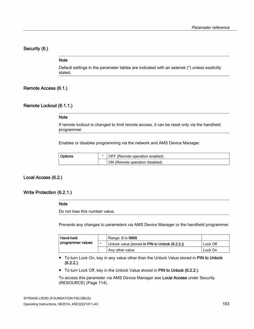
Parameter reference
SITRANS LR250 (FOUNDATION FIELDBUS)
Operating Instructions, 08/2014, A5E32221411-AC 183
Security (6.)
Note
Default settings in the parameter tables are indicated with an asterisk (*) unless explicitly stated.
Remote Access (6.1.)
Remote Lockout (6.1.1.)
Note
If remote lockout is changed to limit remote access, it can be reset only via the handheld programmer.
Enables or disables programming via the network and AMS Device Manager.
Options * OFF (Remote operation enabled)
ON (Remote operation disabled)
Local Access (6.2.)
Write Protection (6.2.1.)
Note
Do not lose this number value.
Prevents any changes to parameters via AMS Device Manager or the handheld programmer.
Hand-held programmer values
Range: 0 to 9999
* Unlock value [stored in PIN to Unlock (6.2.2.)] Lock Off
Any other value Lock On
● To turn Lock On, key in any value other than the Unlock Value stored in PIN to Unlock (6.2.2.).
● To turn Lock Off, key in the Unlock Value stored in PIN to Unlock (6.2.2.).
To access this parameter via AMS Device Manager see Local Access under Security (RESOURCE) (Page 114).

Parameter reference
SITRANS LR250 (FOUNDATION FIELDBUS)
184 Operating Instructions, 08/2014, A5E32221411-AC
PIN to Unlock (6.2.2.)
Note
• Do not lose your Unlock Value: it cannot be displayed once Write Protection (6.2.1.) has been set to a different value.
• A reset to Factory Defaults will not restore the unlock value at time of shipping.
Stores the value to be entered in Write Protection (6.2.1.) to unlock programming. If Write Protection (6.2.1.) is set to a different value, PIN to Unlock (6.2.2.) does not display the Unlock value.
Handheld Programmer Values
Range: 0 to 9999
Value when shipped: 1954. Not restored by a reset to Factory Defaults.
– – – – Display when Lock is on
To access this parameter via AMS Device Manager see Local Access under Security (RESOURCE) (Page 114).
Local Operation (6.2.3.)
Enables or disables programming via the handheld programmer.
Options DISABLED
* ENABLED
Note
Once disabled via the handheld programmer, the parameter is no longer visible via LUI and can only be reset using AMS Device Manager. However, if no communication activity exists for 30 seconds, the parameter will again be visible via LUI.
To access this parameter via AMS Device Manager see Local Display under Setup (LCD) (Page 105).

Parameter reference
SITRANS LR250 (FOUNDATION FIELDBUS)
Operating Instructions, 08/2014, A5E32221411-AC 185
Language (7.)
Selects the language to be used on the LCD.
Options * English
Deutsch
Français
Español
To access this parameter via AMS Device Manager see Local Display under Setup (LCD) (Page 105).
Parameter reference
SITRANS LR250 (FOUNDATION FIELDBUS)
186 Operating Instructions, 08/2014, A5E32221411-AC
8.1 Alphabetical parameter list
Note
For a detailed list of parameters see Parameter Reference (Page 139).
Acknowledge (4.2.9.)
Acknowledge (4.3.9.)
Acknowledge (4.4.9.)
Acknowledge (4.5.9.)
Acknowledge Status (4.2.8.)
Acknowledge Status (4.3.8.)
Acknowledge Status (4.4.8.)
Acknowledge Status (4.5.8.)
AIFB1 (2.6.)
AIFB2 (2.7.)
Alarms and Warnings (2.6.6.)
Algorithm (2.5.7.1.)
Auto False Echo Suppression (2.5.10.1.)
Auto False Echo Suppression Range (2.5.10.2.)
Breakpoints 1-9 (2.5.11.1.)
Breakpoints 10-18 (2.5.11.2.)
Breakpoints 19-27 (2.5.11.3.)
Breakpoints 28-36 (2.5.11.4.)
Breakpoints 37-40 (2.5.11.5.)
Calibration (2.3.7.)
Calibration Interval (4.5.1.)
Calibration Schedule (4.5.)
Channel (2.6.3.)
CLEF (Constrained Leading Edge Fit) Range (2.5.7.4.)
Communication (5.)
Confidence (2.5.9.1.)
Decimal Point (2.6.4.4.)

Parameter reference
SITRANS LR250 (FOUNDATION FIELDBUS)
Operating Instructions, 08/2014, A5E32221411-AC 187
Decimal Point (2.6.5.4.)
Descriptor (2.1.2.)
Device (2.2.)
Device Address (5.2.)
Device Revision (5.5.)
Device Type Identification (5.4.)
Diagnostics (3.)
Dimension A (2.4.1.3.)
Dimension L (2.4.1.4.)
Display (2.6.7.)
Down Sampling (2.5.8.3.)
Echo Lock (2.5.8.1.)
Echo Profile (3.1.)
Echo Quality (2.5.9.)
Echo Select (2.5.7.)
Echo Strength (2.5.9.2.)
Echo Threshold (2.5.7.3.)
Electronics Temperature (3.3.)
Empty Rate per Minute (2.3.8.3.)
Far Range (2.5.2.)
Fault Reset (3.2.)
Fill Rate per Minute (2.3.8.2.)
Filter Time Constant (2.6.7.1.)
Firmware Revision (2.2.2.)
Hardware Revision (2.2.1.)
High Calibration Pt. (2.3.7.2.)
High Level Point (2.3.7.5.)
High Limit Alarm (2.6.6.1.)
High Limit Warning (2.6.6.2.)
Hover Level (2.5.10.3.)
Input Scaling (2.6.4.) ITK Version (5.6.)

Parameter reference
SITRANS LR250 (FOUNDATION FIELDBUS)
188 Operating Instructions, 08/2014, A5E32221411-AC
Language (7.)
LCD Contrast (4.10.)
LCD Fast Mode (4.9.)
Level Offset (2.3.7.6.)
Level Unit (2.3.2.)
Lifetime (expected) (4.2.1.)
Lifetime (expected) (4.3.1.)
Limit Hysteresis (2.6.6.5.)
Linearization (2.4.)
Loader Revision (2.2.3.)
Local Access (6.2.)
Local Operation (6.2.3.)
Loss of Echo (LOE) Timer (2.3.6.)
Low Calibration Point. (2.3.7.1.)
Low Level Point (2.3.7.4.)
Low Limit Alarm (2.6.6.4.)
Low Limit Warning (2.6.6.3.)
Lower Value (2.6.4.1.)
Lower Value (2.6.5.1.)
Main Output (PV– Primary Value) (2.8.1.)
Maintenance Status (4.2.7.)
Maintenance Status (4.3.7.)
Maintenance Status (4.4.7.)
Maintenance Status (4.5.7.)
Manufacturer Date (4.6.)
Manufacturer (5.3.)
Master Reset (4.1.)
Material (2.3.5.)
Maximum Measured Value (3.4.2.)
Maximum Sensor Value (2.5.5.)
Minimum Value (3.3.2.)
Maximum Volume (2.4.1.2.)

Parameter reference
SITRANS LR250 (FOUNDATION FIELDBUS)
Operating Instructions, 08/2014, A5E32221411-AC 189
Measured Values (2.8.)
Message (2.1.3.)
Minimum Measured Value (3.4.1.)
Minimum Sensor Value (2.5.4.)
Minimum Value (3.3.1.)
Mode (2.6.2.)
Near Range (2.5.1.)
Output Scaling (2.6.5.)
Output, no level offsets (SV2 – Secondary Value 2) (2.8.3.)
Output, no linearization (SV1 – Secondary Value 1) (2.8.2.)
Peak Values (3.4.)
Position Detect (2.5.7.2.)
Powered Hours (4.7.)
Power-on Resets (4.8.)
Propagation Factor (2.5.3.)
PV (volume/level) Units (2.3.3.)
Quick Start (1.)
Rate (2.3.8.)
Remaining Device Lifetime (4.2.)
Remaining Lifetime (4.2.3.)
Remaining Sensor Lifetime (4.3.)
Remaining Lifetime (4.3.3.)
Reminder 1 before Lifetime (Required) (4.2.5.)
Reminder 1 before LIfetime (Required) (4.3.5.)
Reminder 1 before Service (Required) (4.4.5.)
Reminder 1 before Calibration (Required) (4.5.5.)
Reminder 2 before Lifetime (Demanded) (4.2.6.)
Reminder 2 before Lifetime (Demanded) (4.3.6.)
Reminder 2 before Service (Demanded) (4.4.6.)
Reminder 2 before Calibration (Demanded) (4.5.6.)
Remote Access (6.1.)
Remote Lockout (6.1.1.)

Parameter reference
SITRANS LR250 (FOUNDATION FIELDBUS)
190 Operating Instructions, 08/2014, A5E32221411-AC
Response Rate (2.3.8.1.)
Sampling (2.5.8.)
Secondary Value (4.11.)
Security (6.)
Sensor (2.3.)
Sensor Offset (2.3.7.3.)
Service (4.)
Service Interval (4.4.1.)
Service Schedule (4.4.)
Setup (2.)
Shaper Mode (2.5.10.4.)
Shots (2.5.6.)
Signal Processing (2.5.)
Simulate Enable (4.12)
Static Revision Number (2.6.1.)
Tag (2.1.1.)
Tag (5.1.)
Temperature Units (2.3.4.)
Time Until Next Calibration (4.5.3.)
Time Until Next Service (4.4.3.)
TVT (Auto False Echo Suppression) setup (2.5.10.)
TVT Shaper (2.5.11.)
Unit (2.3.1.)
Unit (2.6.4.3.)
Unit (2.6.5.3.)
Up Sampling (2.5.8.2.)
Upper Value (2.6.4.2.)
Upper Value (2.6.5.2.)
Vessel Shape (2.4.1.1.)
Volume (2.4.1.)
Write Protection (6.2.1.)
X value (2.4.1.6.)
XY index (2.4.1.5.)
Y value (2.4.1.7.)

SITRANS LR250 (FOUNDATION FIELDBUS)
Operating Instructions, 08/2014, A5E32221411-AC 191
Service and maintenance 9 9.1 Basic safety information
WARNING
Impermissible repair of the device
• Repair must be carried out by Siemens authorized personnel only.
CAUTION
Releasing key lock
Improper modification of parameters could influence process safety.
• Make sure that only authorized personnel may cancel the key locking of devices for safety-related applications.
9.2 Cleaning
The radar device requires no cleaning under normal operating conditions.
Under severe operating conditions, the antenna may require periodic cleaning. If cleaning becomes necessary:
● Note the antenna material and the process medium, and select a cleaning solution that will not react adversely with either.
● Remove the device from service and wipe the antenna clean using a cloth and suitable cleaning solution.
NOTICE
Penetration of moisture into the device
Device damage.
• Make sure when carrying out cleaning and maintenance work that no moisture penetrates the inside of the device.
WARNING
Electrostatic charge
Danger of explosion in hazardous areas if electrostatic charges develop, for example, when cleaning plastic surfaces with a dry cloth.
• Prevent electrostatic charging in hazardous areas.

Service and maintenance
9.3 Maintenance and repair work
SITRANS LR250 (FOUNDATION FIELDBUS)
192 Operating Instructions, 08/2014, A5E32221411-AC
9.3 Maintenance and repair work
The device is maintenance-free. However, a periodic inspection according to pertinent directives and regulations must be carried out.
An inspection can include check of:
● Ambient conditions
● Seal integrity of the process connections, cable entries, and cover screws
● Reliability of power supply, lightning protection, and grounds
WARNING
Maintenance during continued operation in a hazardous area
There is a danger of explosion when carrying out repairs and maintenance on the device in a hazardous area.
• Isolate the device from power.
- or -
• Ensure that the atmosphere is explosion-free (hot work permit).
WARNING
Humid environment
Danger of electric shock.
• Avoid working on the device when it is energized.
• If working on an energized device is necessary, ensure that the environment is dry.
• Make sure when carrying out cleaning and maintenance work that no moisture penetrates the inside of the device.

Service and maintenance
9.3 Maintenance and repair work
SITRANS LR250 (FOUNDATION FIELDBUS)
Operating Instructions, 08/2014, A5E32221411-AC 193
9.3.1 Unit repair and excluded liability
All changes and repairs must be done by qualified personnel, and applicable safety regulations must be followed. Please note the following:
● The user is responsible for all changes and repairs made to the device.
● All new components must be provided by Siemens.
● Restrict repair to faulty components only.
● Do not re-use faulty components.
9.3.2 Part replacement
If the antenna, lens, secondary O-ring, and spring washers require replacement due to damage or failure, they may be replaced without the need for re-calibration if of the same type and size.
Replacing the antenna
Changing to a different antenna type may be performed by a Siemens authorized repair center or personnel.
If the electronics or enclosure require replacement due to damage or failure, please ensure the correct antenna version is used, otherwise a re-calibration will need to be performed by Siemens authorized personnel.
Replacing the lens
1. Remove existing lens by turning it counter-clockwise until it separates from the unit.
2. Replace the O-ring between the lens and process connection with a new one.
3. Carefully thread the replacement lens, and turn it clockwise until resistance is encountered. Do not over-tighten the lens, as this will permanently damage it.
4. For flange installation instructions, see Flanged versions (Page 37).
Note
After installation of the new lens onto the flanged encapsulated antenna version and before mounting on the vessel/tank, some lenses may not appear to lie flush on the device, but this is normal and will not impact performance.

Service and maintenance
9.3 Maintenance and repair work
SITRANS LR250 (FOUNDATION FIELDBUS)
194 Operating Instructions, 08/2014, A5E32221411-AC
Raised-Face flange kits
Description Process connection
size
Part number
Replacement TFMTM 1600 PTFE Lens and Spring Washer Kit for ASME B16.5 Class 150 raised faced
2" A5E32462817
3" A5E32462819
4" A5E32462820
6" A5E32462821
Replacement TFMTM 1600 PTFE Lens and Spring Washer Kit for JIS B 2220 10K raised Face
50A A5E32462822
80A A5E32462823
100A A5E32462824
150A A5E32462825
Replacement TFMTM 1600 PTFE Lens and Spring Washer Kit for EN 1092-1 PN10/16 type B1 raised face
DN50 A5E32462826
DN80 A5E32462827
DN100 A5E32462828
DN150 A5E32462829
Spare part kits
Description Process connection size
Part number
ISO2852, Hygienic encapsulated antenna Lens and silicon O-ring 2" A5E32572731
3" A5E32572745
4" A5E32572747
DIN11851, Hygienic encapsulated antenna Lens and silicon O-ring
DN50 A5E32572758
DN80 A5E32572770
DN100 A5E32572772
DIN11864-1, Hygienic encapsulated antenna Lens and silicon O-ring
DN50 A5E32572773
DN80 A5E32572779
DN100 A5E32572782
DIN11864-2/3, Hygienic encapsulated antenna Lens and silicon O-ring
DN50 A5E32572785
DN80 A5E32572790
DN100 A5E32572791
Tuchenhagen, Hygienic encapsulated antenna Lens and silicon O-ring
Type F A5E32572794
Type N A5E32572795
Note
For more information about accessories such as clamps, seals and process connections, please see the catalog on the product page (http://www.siemens.com/LR250).

Service and maintenance
9.4 Disposal
SITRANS LR250 (FOUNDATION FIELDBUS)
Operating Instructions, 08/2014, A5E32221411-AC 195
9.4 Disposal
Note
Special disposal required
The device includes components that require special disposal.
• Dispose of the device properly and environmentally through a local waste disposal contractor.

Service and maintenance
9.4 Disposal
SITRANS LR250 (FOUNDATION FIELDBUS)
196 Operating Instructions, 08/2014, A5E32221411-AC

SITRANS LR250 (FOUNDATION FIELDBUS)
Operating Instructions, 08/2014, A5E32221411-AC 197
Diagnosing and troubleshooting 10
1. Check the following: – There is power at the device. – The LCD shows the relevant data. – If any fault codes are being displayed see General Fault Codes (Page 199) for a detailed
list.
2. Verify that the wiring connections are correct.
3. See the table below for specific symptoms.
Symptom Corrective action
The device cannot be programmed via FF.
• Make sure Remote Lockout (6.1.1.) is set to the unlock value
• Ensure block is Out of Service
You try to set a SITRANS LR250 parameter via remote communications but the parameter remains unchanged.
• Ensure Remote Lockout (6.1.1.) is disabled.
• Ensure Write Protection (6.2.1.) is set to the unlock value.
• Ensure block is Out of Service
The AIFB output equals the display value but does not correspond to actual material level.
• Ensure the Channel selection and Scaling in AIFB 1 are correctly entered
• Ensure AIFBs are scheduled and in Auto mode
• Ensure High Calibration Point is correctly entered
• View the echo profile to see if the wrong echo is being selected. If so, see Operation Troubleshooting (Page 204) for possible causes and corrective action
The AIFB output is not equal to the displayed value (regardless of actual material level).
• Confirm you are looking at the AIFB Output
• Ensure AIFBs are scheduled and in Auto mode
• Ensure scaling has not been programmed into the controller: all scaling should be performed by the LR250
• Check the network to ensure the controller is communicating with the LR250
Not able to change parameters via LUI. • Ensure Local Operation (6.2.3.) is enabled
Not able to change parameters, such as low calibration point.
• Ensure block is in Out of Service mode
If you continue to experience problems go to our website and check the FAQs for SITRANS LR250:
Product page (http://www.siemens.com/LR250), or contact your Siemens representative.

Diagnosing and troubleshooting
10.1 Device status icons
SITRANS LR250 (FOUNDATION FIELDBUS)
198 Operating Instructions, 08/2014, A5E32221411-AC
10.1 Device status icons
Icon Priority Level
Meaning
1 • Maintenance alarm
• Measurement values are not valid
2 • Maintenance warning: maintenance demanded immediately
• Measured signal still valid
3 • Maintenance required
• Measured signal still valid
1 • Process value has reached an alarm limit
2 • Process value has reached a warning limit
3 • Process value has reached a tolerance limit
1 • Configuration error
• Device will not work because one or more parameters/components is incorrectly configured
2 • Configuration warning
• Device can work but one or more parameters/components is incorrectly configured
3 • Configuration changed
• Device parameterization not consistent with parameterization in project. Look for info text.
1 • Manual operation (local override)
• Communication is good; device is in manual mode.
2 • Simulation or substitute value
• Communication is good; device is in simulation mode or works with substitute values.
3 • Out of operation
• Communication is good; device is out of action.
• No data exchange
• Write access enabled
• Write access disabled

Diagnosing and troubleshooting
10.2 General fault codes
SITRANS LR250 (FOUNDATION FIELDBUS)
Operating Instructions, 08/2014, A5E32221411-AC 199
10.2 General fault codes
Note
• If more than one fault is present, the device status indicator and text for each fault alternate at 2 second intervals.
Code/ Icon
Meaning Corrective Action
S: 0
The device was unable to get a measurement within the Fail-safe LOE Timer period. Possible causes: faulty installation, antenna material buildup, foaming/other adverse process conditions, invalid configuration range.
• Ensure installation details are correct.
• Ensure no antenna material buildup. Clean if necessary.
• Adjust process conditions to minimize foam or other adverse conditions.
• Correct configuration range.
• If fault persists, contact your local Siemens representative.
S: 2
Unable to collect profile because of a power condition that is outside the operating range of the device.
Repair required: contact your local Siemens representative.
S: 3
Device is nearing its lifetime limit as defined in Remaining Lifetime (4.2.3.) and has triggered a Maintenance Required reminder (4.2.5.).
Replacement is recommended
S: 4
Device is nearing its lifetime limit as defined in Remaining Lifetime (4.2.3.) and has triggered a Maintenance Demanded reminder (4.2.6.).
Replacement is recommended.
S: 6
Sensor is nearing its lifetime limit as defined in Remaining Lifetime (4.3.3.) and has triggered a Maintenance Required reminder (4.3.5.).
Replacement is recommended.
S: 7
Sensor is nearing its lifetime limit as defined in Remaining Lifetime (4.3.3.) and has triggered a Maintenance Demanded reminder (4.3.6.).
Replacement is recommended.
S: 8
Service interval (4.4.1.) has expired and has triggered a Maintenance Required reminder (4.4.5.).
Perform service.

Diagnosing and troubleshooting
10.2 General fault codes
SITRANS LR250 (FOUNDATION FIELDBUS)
200 Operating Instructions, 08/2014, A5E32221411-AC
Code/ Icon
Meaning Corrective Action
S: 9
Service interval (4.4.1.) has expired and has triggered a Maintenance Demanded reminder (4.4.6.).
Perform service.
S: 10
Input parameters Low Calibration Point (2.3.7.1.) and High Calibration Point (2.3.7.2.) are the same.
• Check calibration settings of device.
• Ensure settings for High Calibration Point and Low Calibration Point are different.
S: 11
Internal temperature sensor failure. Repair required: contact your local Siemens representative.
S: 12
Internal temperature of device has exceeded specifications: it is operating outside its temperature range.
• Relocate device and/or lower process temperature enough to cool device.
• Inspect for heat-related damage and contact your local Siemens representative if repair is required.
• Fault code will persist until a manual reset is performed using AMS or the LCD interface.
S: 17
Calibration interval (4.5.1.) has expired and has triggered a Maintenance Required reminder (4.5.5.).
Perform calibration.
S: 18
Calibration interval (4.5.1.) has expired and has triggered a Maintenance Demanded reminder (4.5.6.).
Perform calibration.
S: 22
Time Base Fault Hardware problem: contact your local Siemens representative.
S: 28
Internal device failure caused by a RAM memory error.
Repair required: contact your local Siemens representative.
S: 29
EEPROM damaged. Repair required: contact your local Siemens representative
S: 31
Flash error. Repair required: contact your local Siemens representative
S: 33
Factory calibration for the internal temperature sensor has been lost.
Repair required: contact your local Siemens representative

Diagnosing and troubleshooting
10.2 General fault codes
SITRANS LR250 (FOUNDATION FIELDBUS)
Operating Instructions, 08/2014, A5E32221411-AC 201
Code/ Icon
Meaning Corrective Action
S: 34
Factory calibration for the device has been lost. Repair required: contact your local Siemens representative
S: 35
Factory calibration for the device has been lost. Repair required: contact your local Siemens representative
S: 36
Unable to start microwave module. Repair required: contact your local Siemens representative
S: 37
Measurement hardware problem. Repair required: contact your local Siemens representative
S: 38
Microwave module hardware failure: unable to calculate distance measurement.
Repair required: contact your local Siemens representative
S: 43
Factory calibration for the radar receiver has been lost.
Repair required: contact your local Siemens representative.
S: 92
Corrupt Stack Contact your local Siemens representative and provide configuration file and FB schedule.
S: 93
High Stack Contact your local Siemens representative and provide configuration file and FB schedule.
S: 94
Data Safe Read Re-apply configuration and cycle power. If fault persists, contact your local Siemens representative.
S: 95
Data Safe Write Re-apply configuration and cycle power. If fault persists, contact your local Siemens representative.
S: 96
Safe Process Data Corrupt Contact your local Siemens representative and provide configuration file and FB schedule.
S: 97
Board Voltage Hardware problem: contact your local Siemens representative.

Diagnosing and troubleshooting
10.2 General fault codes
SITRANS LR250 (FOUNDATION FIELDBUS)
202 Operating Instructions, 08/2014, A5E32221411-AC
Code/ Icon
Meaning Corrective Action
S: 98
ADC Failed Hardware problem: contact your local Siemens representative.
S: 99
Prof. Clip Hardware problem. If fault persists contact your local Siemens representative.
S: 100
Few Shots Hardware problem. If fault persists contact your local Siemens representative.
S: 101
Meas. Err. Reset configuration. If fault persists contact your local Siemens representative and provide configuration file and FB schedule.
S: 102
No Shots Hardware problem. If fault persists contact your local Siemens representative.
S: 103
Meas. Corrupt Contact your local Siemens representative and provide configuration file and FB schedule.
S: 104
DMA Error Hardware problem. If fault persists contact your local Siemens representative.
S: 105
Seq. Corrupt Contact your local Siemens representative and provide configuration file and FB schedule.
S: 106
Seq. CP Re-install firmware (firmware upgrade). If fault persists contact your local Siemens representative.
S: 107
Seq. Duration Increase update rate limit. If fault persists contact your local Siemens representative.
S: 108
BC Corrupt Contact your local Siemens representative and provide configuration file and FB schedule.
S: 109
BC Start Re-install firmware (firmware upgrade). If fault persists contact your local Siemens representative.

Diagnosing and troubleshooting
10.2 General fault codes
SITRANS LR250 (FOUNDATION FIELDBUS)
Operating Instructions, 08/2014, A5E32221411-AC 203
Code/ Icon
Meaning Corrective Action
S: 110
BC Stop Re-install firmware (firmware upgrade). If fault persists contact your local Siemens representative.
S: 111
BC Duration Hardware problem. If fault persists contact your local Siemens representative.
S: 112
CPU Fault Hardware problem. If fault persists contact your local Siemens representative.
S: 113
Data Bus Hardware problem. If fault persists contact your local Siemens representative.
S: 114
Addr Bus Hardware problem. If fault persists contact your local Siemens representative.
S: 115
Spur SW Hardware problem. If fault persists contact your local Siemens representative.
S: 116
Spur HW Hardware problem. If fault persists contact your local Siemens representative.
S: 117
SV High Verify TB not in simulation mode. If fault persists contact your local Siemens representative.
S: 118
SV Low Verify TB not in simulation mode. If fault persists contact your local Siemens representative.

Diagnosing and troubleshooting
10.3 Operation troubleshooting
SITRANS LR250 (FOUNDATION FIELDBUS)
204 Operating Instructions, 08/2014, A5E32221411-AC
10.3 Operation troubleshooting
Operating symptoms, probable causes, and resolutions.
Symptom Cause Action
Display shows
level or target is out of range • check specifications
• check Low Calibration Pt. (2.3.7.1.)
• increase Confidence (2.5.9.1.)
Display shows
material build-up on antenna • clean the antenna
• re-locate SITRANS LR250
Display shows
location or aiming:
• poor installation
• flange not level
• Auto False Echo Suppression may be incorrectly applied
• check to ensure nozzle is vertical
• ensure end of antenna protrudes from end of nozzle
• review Auto False Echo Suppression (Page 265)
• ensure Auto False Echo Suppression Range is set correctly
Display shows
antenna malfunction:
• temperature too high
• physical damage
• excessive foam
• multiple echoes
• check temperature in Maximum Value (3.3.2.)
• use foam deflector or stillpipe
• relocate
• use a defoamer
• set Algorithm (2.5.7.1.) to tF (trueFirst echo)
Reading does not change, but the level does
SITRANS LR250 processing wrong echo, for example, vessel wall, or structural member
• re-locate SITRANS LR250
• check nozzle for internal burrs or welds
• rotate device 90°
• use Auto False Echo Suppression (2.5.10.1.)
• if necessary: see Auto False Echo Suppression (Page 265)
Measurement is consistently off by a constant amount
• setting for Low Calibration Point (2.3.7.1.) not correct
• setting for Sensor Offset (2.3.7.3.) not correct
• check distance from sensor reference point to Low Calibration Point (2.3.7.1.)
• check Sensor Offset (2.3.7.3.)
Screen blank power error • check nameplate rating against voltage supply
• check power wiring or source
too much load resistance • change barrier type, or
• remove something from the loop, or
• increase supply voltage
• reduce wire distance or use larger gage wire

Diagnosing and troubleshooting
10.3 Operation troubleshooting
SITRANS LR250 (FOUNDATION FIELDBUS)
Operating Instructions, 08/2014, A5E32221411-AC 205
Symptom Cause Action
Reading erratic echo confidence weak • refer to Confidence (2.5.9.1.)
• use Auto False Echo Suppression (2.5.10.1.) and Auto False Echo Suppression Range (2.5.10.2.)
• use foam deflector or stillpipe
liquid surface vortexed • decrease Fill Rate (2.3.8.2..)
• relocate device to side pipe
• increase confidence threshold in Echo Threshold (2.5.7.3.)
material filling • Re-locate SITRANS LR250
Reading response slow
Fill Rate (2.3.8.2.) setting incorrect
• increase measurement response if possible
Reads correctly but occasionally reads high when vessel is not full
• detecting close range echo
• build up near top of vessel or nozzle
• nozzle problem
• clean the antenna
• use Auto False Echo Suppression (2.5.10.1.) and Auto False Echo Suppression Range (2.5.10.2.)
Level reading lower than actual material level
• material is within Near Range zone
• multiple echoes processed
• decrease Near Range (2.5.1.) (minimum value depends on antenna type)
• raise SITRANS LR250
• ensure Algorithm (2.5.7.1.) is set to tF (First echo)
• vessel near empty and low dK material
• ensure Material (1.2.) selection is LIQUID LOW DK
• set Position Detect (2.5.7.2.) to Hybrid
• check the setting for CLEF Range (2.5.7.4.): see the table below Propogation Factor (2.5.3.) for recommended settings

Diagnosing and troubleshooting
10.3 Operation troubleshooting
SITRANS LR250 (FOUNDATION FIELDBUS)
206 Operating Instructions, 08/2014, A5E32221411-AC
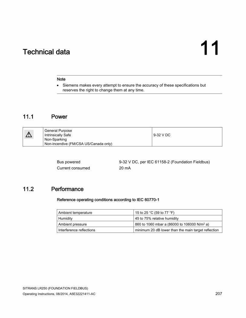
SITRANS LR250 (FOUNDATION FIELDBUS)
Operating Instructions, 08/2014, A5E32221411-AC 207
Technical data 11
Note
• Siemens makes every attempt to ensure the accuracy of these specifications but reserves the right to change them at any time.
11.1 Power
General Purpose Intrinsically Safe Non-Sparking Non-incendive (FM/CSA US/Canada only)
9-32 V DC
Bus powered 9-32 V DC, per IEC 61158-2 (Foundation Fieldbus)
Current consumed 20 mA
11.2 Performance
Reference operating conditions according to IEC 60770-1
Ambient temperature 15 to 25 °C (59 to 77 °F)
Humidity 45 to 75% relative humidity
Ambient pressure 860 to 1060 mbar a (86000 to 106000 N/m2 a)
Interference reflections minimum 20 dB lower than the main target reflection

Technical data
11.2 Performance
SITRANS LR250 (FOUNDATION FIELDBUS)
208 Operating Instructions, 08/2014, A5E32221411-AC
Measurement Accuracy (measured in accordance with IEC 60770-1)
Maximum measured error =3 mm (0.12")1) 2) 3) including hysteresis and non-repeatability
Frequency K-band
Maximum measurement range4) 1.5" antenna 10 m (32.8 ft)5)
2" threaded PVDF antenna
2"/DN50/50A Flangedencapsulated antenna (FEA)
2" ISO 2852, DN50 DIN11864-1/2/3, DN50 DIN11851,Tuchenhagen Types F and N Hygienic encapsulated antenna (HEA)
all other versions 20 m (65.6 ft)
Minimum detectable distance 50 mm (2") from end of antenna6)
Update time7) minimum 1 second, depending on settings for Response Rate (2.3.8.1.) and LCD Fast Mode (4.9.).
Influence of ambient temperature < 0.003% / K (average over full temperature range, referenced to maximum range)
Dielectric constant of material measured dK > 1.6 [antenna and application dependent8)]
Memory non-volatile EEPROM
no battery required
1) The statistical accuracy is typically 3 mm (0.12") 90% of the time, when tested in accordance with IEC 60770-1.
2) Under severe EMI/EMC environments per IEC 61326-1 or NAMUR NE21, the device error may increase to a maximum of 10 mm (0.4").
3) For 2" threaded PVDF antenna, Flanged encapsulated antennas and Hygienic encapsulated antennas, the maximum measured error <500 mm from the sensor reference point =25 mm (1").
4) From sensor reference point: see Dimension drawings (Page 215) and Flanged Horn with extension (Page 222).
5) 20 m (65.6 ft) possible in a stillpipe/bypass
6) Minimum range is antenna length +50 mm (2"). See Dimension drawings (Page 215).
7) Reference conditions: Response Rate (2.4.1.) set to FAST, LCD Fast Mode (4.9.) set to ON.
8) For 1.5" (40 mm) antenna and 2" (50 mm) threaded PVDF antenna, 2"/DN50/50A flanged encapsulated antenna and 2" ISO 2852, DN50 DIN 11864-1/2/3, DN50 DIN11851, Tuchenhagen Types F and N hygienic encapsulated antenna the minimum dK is limited to 3 unless a stillpipe is used.
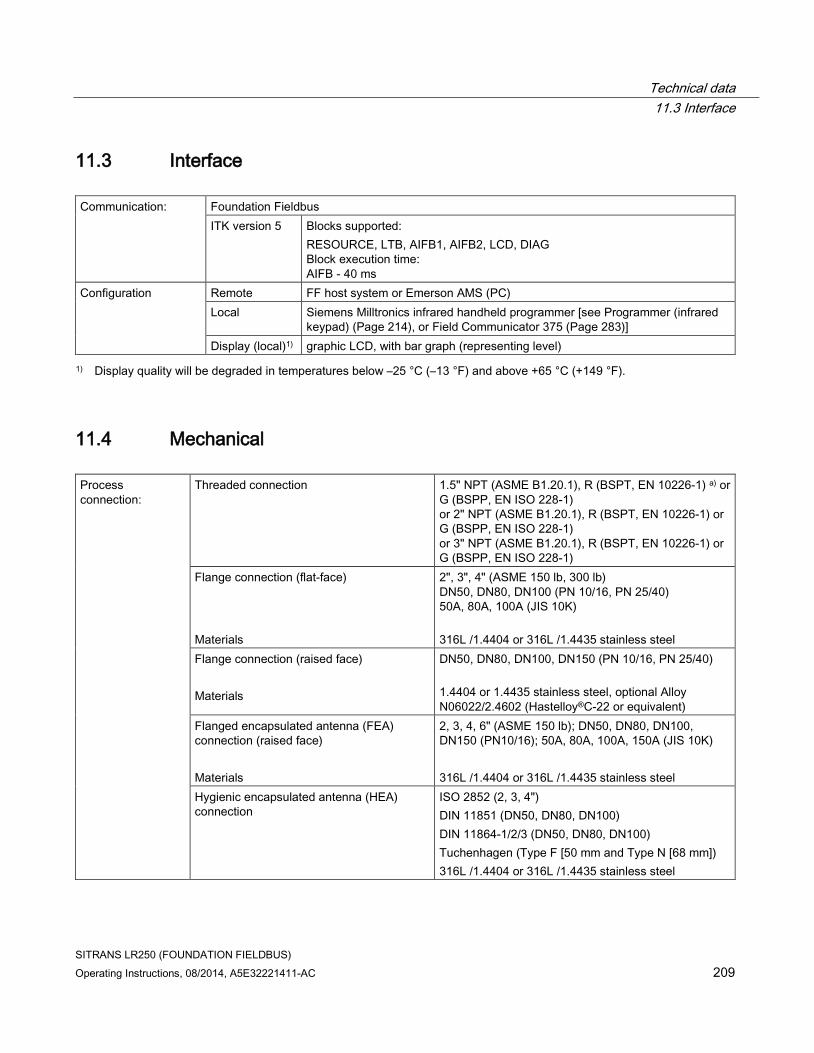
Technical data
11.3 Interface
SITRANS LR250 (FOUNDATION FIELDBUS)
Operating Instructions, 08/2014, A5E32221411-AC 209
11.3 Interface
Communication: Foundation Fieldbus
ITK version 5 Blocks supported:
RESOURCE, LTB, AIFB1, AIFB2, LCD, DIAG Block execution time: AIFB - 40 ms
Configuration Remote FF host system or Emerson AMS (PC)
Local Siemens Milltronics infrared handheld programmer [see Programmer (infrared keypad) (Page 214), or Field Communicator 375 (Page 283)]
Display (local)1) graphic LCD, with bar graph (representing level)
1) Display quality will be degraded in temperatures below –25 °C (–13 °F) and above +65 °C (+149 °F).
11.4 Mechanical
Process connection:
Threaded connection 1.5" NPT (ASME B1.20.1), R (BSPT, EN 10226-1) a) or G (BSPP, EN ISO 228-1) or 2" NPT (ASME B1.20.1), R (BSPT, EN 10226-1) or G (BSPP, EN ISO 228-1) or 3" NPT (ASME B1.20.1), R (BSPT, EN 10226-1) or G (BSPP, EN ISO 228-1)
Flange connection (flat-face)
Materials
2", 3", 4" (ASME 150 lb, 300 lb) DN50, DN80, DN100 (PN 10/16, PN 25/40) 50A, 80A, 100A (JIS 10K)
316L /1.4404 or 316L /1.4435 stainless steel
Flange connection (raised face)
Materials
DN50, DN80, DN100, DN150 (PN 10/16, PN 25/40)
1.4404 or 1.4435 stainless steel, optional Alloy N06022/2.4602 (Hastelloy®C-22 or equivalent)
Flanged encapsulated antenna (FEA) connection (raised face)
Materials
2, 3, 4, 6" (ASME 150 lb); DN50, DN80, DN100, DN150 (PN10/16); 50A, 80A, 100A, 150A (JIS 10K)
316L /1.4404 or 316L /1.4435 stainless steel
Hygienic encapsulated antenna (HEA) connection
ISO 2852 (2, 3, 4")
DIN 11851 (DN50, DN80, DN100)
DIN 11864-1/2/3 (DN50, DN80, DN100)
Tuchenhagen (Type F [50 mm and Type N [68 mm])
316L /1.4404 or 316L /1.4435 stainless steel

Technical data
11.4 Mechanical
SITRANS LR250 (FOUNDATION FIELDBUS)
210 Operating Instructions, 08/2014, A5E32221411-AC
Materials
ISO 2852 (2, 3, 4")
DIN 11864-3 (DN50, DN80, DN100)
clamp: 304/1.4301 stainless steel
Tuchenhagen (Type F [50 mm] and Type N [68 mm])
316L /1.4404 or 316L /1.4435 stainless steel
clamp: 304/1.4301 stainless steel
nut connection: 303/1.4305 stainless steel
DIN 11851/11864-1 (DN50, DN80. DN100)
captive slotted nut connection: 304L/1.4307
DIN 11864-2 (DN50, DN80. DN100)
mounting nuts and bolts: 304/1.4301 stainless steel
Antenna: Horn Materials
standard 1.5" (40 mm), 2" (50 mm), 3" (80 mm), and 4" (100 mm) horn, optional 100 mm (4") horn extension 316L stainless steel with PTFE emitter optional Alloy N06022/2.4602 (Hastelloy®C-22 or equivalent) with PTFE emitter
Threaded PVDF antenna
Wetted materials
2" (50 mm)
PVDF (Polyvinylidene fluoride)
Flanged encapsulated antenna
Wetted materials
316L /1.4404 or 316L /1.4435 stainless steel
TFMTM 1600 PTFE lens
Hygienic encapsulated antenna
Wetted material
316L/1.4404 or 316L/1.4435 stainless steel
TFMTM 1600 PTFE (plus chosen seal)
Enclosure Construction aluminum, polyester powder-coated
Conduit entry 2 x M20x1.5, or 2 x ½" NPT
Ingress protection Type 4X/NEMA 4X, Type 6/NEMA 6, IP67, IP68
Weight (excluding extensions):
1.5" threaded connection with 1.5" horn antenna
approximately 5.1 kg (11.2 lb)
2" threaded connection with 2" horn antenna
approximately 5.5 kg (12.1 lb)
3" threaded connection with 3" horn antenna
approximately 7.0 kg (15.4 lb)
2" threaded PVDF antenna approximately 3.3 kg (7.27 lb)
DN50 PN 10/16 or 2" 150 lb flat-face flange with 2" horn antenna
approximately 8 kg (17.6 lb)
DN100 PN 25/40 or 4" ASME 300 lb flat-face flange with 4" horn antenna
approximately 17.4 kg (38.3 lb)
DN50 PN 10/16 raised-face flange with 2" horn antenna
approximately 6 kg (13.2 lb)

Technical data
11.4 Mechanical
SITRANS LR250 (FOUNDATION FIELDBUS)
Operating Instructions, 08/2014, A5E32221411-AC 211
DN100 PN 25/40 raised-face flange with 4" horn antenna
approximately 11.3 kg (24.9 lb)
2" ASME 150 lb FEA approximately 7.0 kg (15.4 lb)
3" ASME 150 lb FEA approximately 10.7 kg (23.6 lb)
4" ASME 150 lb FEA approximately 13.1 kg (28.9 lb)
6" ASME 150 lb FEA approximately 17.7 kg (39 lb)
DN50 PN 10/16 FEA approximately 7.1 kg (15.7 lb)
DN80 PN 10/16 FEA approximately 10.1 kg (22.3 lb)
DN100 PN 10/16 FEA approximately 11.1 kg (24.5 lb)
DN150 PN 10/16 FEA approximately 15.9 kg (35.1 lb)
50 A JIS 10K FEA approximately 6.5 kg (14.3 lb)
80 A JIS 10K FEA approximately 9 kg (19.8 lb)
100 A JIS 10K FEA approximately 10.1 kg (22.3 lb)
150 A JIS 10K FEA approximately 16.3 kg (35.9 lb)
2" ISO 2852 HEA approximately 4.7 kg (10.4 lb)
3" ISO 2852 HEA approximately 6.3 kg (13.9 lb)
4" ISO 2852 HEA approximately 6.8 kg (15 lb)
DN50 DIN 11864-1 HEA approximately 4.8 kg (10.6 lb)
DN80 DIN 11864-1 HEA approximately 6.7 kg (14.8 lb)
DN100 DIN 11864-1 HEA approximately 7.1 kg (15.7 lb)
DN50 DIN 11864-2 HEA approximately 5.0 kg (11 lb)
DN80 DIN 11864-2 HEA approximately 7.2 kg (15.9 lb)
DN100 DIN 11864-2 HEA approximately 7.9 kg (17.4 lb)
DN50 DIN 11864-3 HEA approximately 4.8 kg (10.6 lb)
DN80 DIN 11864-3 HEA approximately 6.6 kg (14.6 lb)
DN100 DIN 11864-3 HEA approximately 7.2 kg (15.9 lb)
DN50 DIN 11851 HEA approximately 4.8 kg (10.6 lb)
DN80 DIN 11851 HEA approximately 6.8 kg (15 lb)
DN100 DIN 11851 HEA approximately 7.2 kg (15.9 lb)
Tuchenhagen Type F HEA approximately 4.8 kg (10.6 lb)
Tuchenhagen Type N HEA approximately 4.9 kg (10.8 lb)
a) For use with 1.5" (40 mm) horn antennas only.

Technical data
11.5 Environmental
SITRANS LR250 (FOUNDATION FIELDBUS)
212 Operating Instructions, 08/2014, A5E32221411-AC
11.5 Environmental
Note
• For the specific configuration you are about to use or install, check transmitter nameplate and see Approvals (Page 213).
• Use appropriate conduit seals to maintain IP or NEMA rating.
Location indoor/ outdoor
Altitude 5000 m (16,404 ft) max.
Ambient temperature −40 to +80 °C (−40 to +176 °F) Relative humidity suitable for outdoor
Type 4X/NEMA 4X, Type 6/NEMA 6, IP67, IP68 enclosure (see note above)
Installation category I
Pollution degree 4
11.6 Process
Note
The maximum temperature is dependent on the process connection, antenna materials, and vessel pressure. For more detailed information see Maximum Process Temperature Chart (Page 269) and Process Pressure/Temperature derating curves (Page 270).
Temperature at process connection
Standard Horn antenna (Threaded or Flanged):
with FKM O-ring −40 to +200 °C (−40 to +392 °F) with FFKM O-ring −20 to +200 °C (−4 to +392 °F)
2" NPT / BSPT / G Threaded PVDF antenna: −40 to +80 °C (−40 to +176 °F) Flanged encapsulated antenna (FEA) -40 to +170 °C (−40 to +338 °F)
Hygienic encapsulated antenna (HEA) -40 to +170 °C (−40 to +338 °F) with FKM seals used on process connection: -20 to +170 °C (-4 to +338 °F)
with EPDM seals used on process connection: -40 to +120 °C (-40 to +248 °F)
Pressure (vessel) Refer to process connection tag and Process Pressure/Temperature derating curves (Page 270).
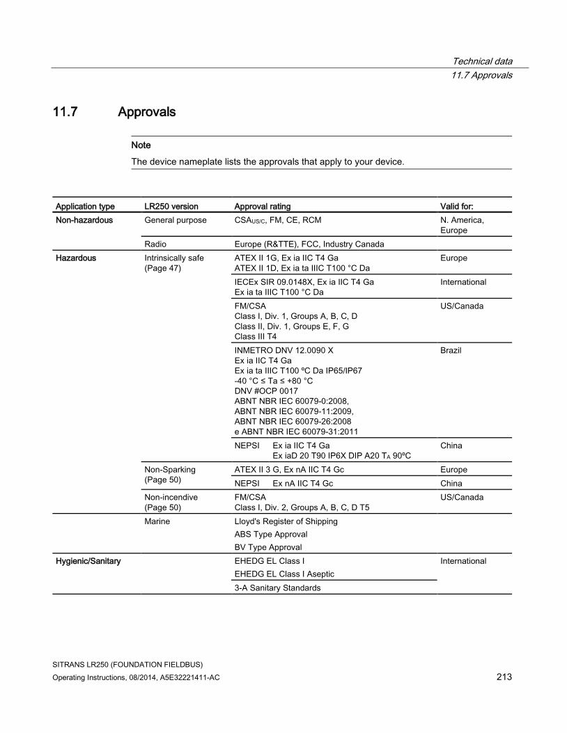
Technical data
11.7 Approvals
SITRANS LR250 (FOUNDATION FIELDBUS)
Operating Instructions, 08/2014, A5E32221411-AC 213
11.7 Approvals
Note
The device nameplate lists the approvals that apply to your device.
Application type LR250 version Approval rating Valid for:
Non-hazardous
General purpose CSAUS/C, FM, CE, RCM N. America, Europe
Radio Europe (R&TTE), FCC, Industry Canada
Hazardous Intrinsically safe (Page 47)
ATEX II 1G, Ex ia IIC T4 Ga ATEX II 1D, Ex ia ta IIIC T100 °C Da
Europe
IECEx SIR 09.0148X, Ex ia IIC T4 Ga Ex ia ta IIIC T100 °C Da
International
FM/CSA Class I, Div. 1, Groups A, B, C, D Class II, Div. 1, Groups E, F, G Class III T4
US/Canada
INMETRO DNV 12.0090 X Ex ia IIC T4 Ga Ex ia ta IIIC T100 ºC Da IP65/IP67 -40 °C ≤ Ta ≤ +80 °C DNV #OCP 0017 ABNT NBR IEC 60079-0:2008, ABNT NBR IEC 60079-11:2009, ABNT NBR IEC 60079-26:2008 e ABNT NBR IEC 60079-31:2011
Brazil
NEPSI Ex ia IIC T4 Ga Ex iaD 20 T90 IP6X DIP A20 TA 90ºC
China
Non-Sparking (Page 50)
ATEX II 3 G, Ex nA IIC T4 Gc Europe
NEPSI Ex nA IIC T4 Gc China
Non-incendive (Page 50)
FM/CSA Class I, Div. 2, Groups A, B, C, D T5
US/Canada
Marine Lloyd's Register of Shipping
ABS Type Approval
BV Type Approval
Hygienic/Sanitary EHEDG EL Class I
EHEDG EL Class I Aseptic
International
3-A Sanitary Standards

Technical data
11.8 Programmer (infrared keypad)
SITRANS LR250 (FOUNDATION FIELDBUS)
214 Operating Instructions, 08/2014, A5E32221411-AC
11.8 Programmer (infrared keypad)
Note
Battery is non-replaceable with a lifetime expectancy of 10 years in normal use. To estimate the lifetime expectancy, check the nameplate on the back for the serial number. The first six numbers show the production date (mmddyy), for example, serial number 032608101V was produced on March 26, 2008.
Siemens Milltronics Infrared IS (Intrinsically Safe) Handheld Programmer for hazardous and all other locations (battery is non-replaceable).
Approvals CE FM/CSA Class I, II, III, Div. 1, Gr. A to G T6 ATEX II 1GD Ex ia IIC T4 Ga Ex iaD 20 T135 °C IECEx Ex ia IIC T4 Ga Ex iaD 20 T135 °C INMETRO Ex ia IIC T4 Ga Ex ia IIIC T135 °C Da
Ambient temperature −20 to +50 °C (−5 to +122 °F) Interface proprietary infrared pulse signal
Power 3 V non-replaceable lithium battery
Weight 150 g (0.3 lb)
Color black
Part number 7ML1930-1BK

SITRANS LR250 (FOUNDATION FIELDBUS)
Operating Instructions, 08/2014, A5E32221411-AC 215
Dimension drawings 12 12.1 Threaded horn antenna
Note
• Process temperature and pressure capabilities are dependent upon information on the process connection tag. Reference drawing listed on the tag is available for download from our website under Support/Installation drawings/Level Measurement/Continuous - Radar/LR250: Product page (http://www.siemens.com/LR250)
• Process connection drawings are also available for download from the Installation Drawings page.
• Signal amplitude increases with horn diameter, so use the largest practical size.
• Optional extensions can be installed below the threads.

Dimension drawings
12.1 Threaded horn antenna
SITRANS LR250 (FOUNDATION FIELDBUS)
216 Operating Instructions, 08/2014, A5E32221411-AC
① ½" NPT cable entry, or M20 cable gland ⑦ enclosure/electronics
② threaded cover ⑧ retaining collar
③ 2" horn ⑨ process connection tag
④ 3" horn ⑩ horn
⑤ 4" horn ⑪ sensor reference point
⑥ horn O.D.
Dimensions in mm (inch)

Dimension drawings
12.1 Threaded horn antenna
SITRANS LR250 (FOUNDATION FIELDBUS)
Operating Instructions, 08/2014, A5E32221411-AC 217
Threaded horn dimensions
Antenna Type
Antenna O.D. in mm (inch)
Height to sensor reference point, in mm (inch) a) Beam Angle
(°)b) Measurement range, in m (ft) 1-1/2" threaded
connection 2" threaded connection
3" threaded connection
1.5" 39.8 (1.57) 135 (5.3) N/A N/A 19 10 (32.8)
2" 47.8 (1.88) N/A 166 (6.55) 180 (7.09) 15 20 (65.6)
3" 74.8 (2.94) N/A 199 (7.85) 213 (8.39) 10 20 (65.6)
4" 94.8 (3.73) N/A 254 (10) 268 (10.55) 8 20 (65.6)
a) Height from bottom of horn to sensor reference point as shown: see dimension drawing.
b) -3dB in the direction of the polarization axis. For an illustration, see Polarization reference point (Page 31).

Dimension drawings
12.2 Threaded horn antenna with extension
SITRANS LR250 (FOUNDATION FIELDBUS)
218 Operating Instructions, 08/2014, A5E32221411-AC
12.2 Threaded horn antenna with extension
① ½" NPT cable entry, or M20 cable gland ⑦ enclosure/electronics
② threaded cover ⑧ retaining collar
③ 2" horn ⑨ process connection tag
④ 3" horn ⑩ horn
⑤ 4" horn ⑪ sensor reference point
⑥ horn O.D.
Dimensions in mm (inch)

Dimension drawings
12.2 Threaded horn antenna with extension
SITRANS LR250 (FOUNDATION FIELDBUS)
Operating Instructions, 08/2014, A5E32221411-AC 219
Threaded horn with extension dimensions
Antenna Type
Antenna O.D. in mm (inch)
Height to sensor reference point, in mm (inch) a) Beam Angle (°) b)
Measurement range in m (ft)
1-1/2" threaded connection
2" threaded connection
3" threaded connection
1.5" 39.8 (1.57) 235 (9.25) N/A N/A 19 10 (32.8)
2" 47.8 (1.88) N/A 266 (10.47) 280 (11.02) 15 20 (65.6)
3" 74.8 (2.94) N/A 299 (11.77) 313 (12.32) 10 20 (65.6)
4" 94.8 (3.73) N/A 354 (13.94) 368 (14.49) 8 20 (65.6)
a) Height from bottom of horn to sensor reference point as shown: see dimension drawing.
b) -3dB in the direction of the polarization axis. For an illustration, see Polarization reference point (Page 31).

Dimension drawings
12.3 Flanged horn antenna
SITRANS LR250 (FOUNDATION FIELDBUS)
220 Operating Instructions, 08/2014, A5E32221411-AC
12.3 Flanged horn antenna
① ½" NPT cable entry, or M20 cable gland ⑥ flange
② threaded cover ⑦ name-plate
③ horn ⑧ retaining collar
④ horn O.D. ⑨ process connection tag
⑤ enclosure/electronics ⑩ sensor reference point
Dimensions in mm (inch)

Dimension drawings
12.3 Flanged horn antenna
SITRANS LR250 (FOUNDATION FIELDBUS)
Operating Instructions, 08/2014, A5E32221411-AC 221
Flanged Horn dimensions
Nominal horn size in mm (inch)
Horn O.D. in mm (inch)
Height to sensor reference point, in mm (inch)a)
Beam angle (°)b)
Measurement range, in m (ft)
Stainless steel flange: raised or flat-face
Optional alloy flange c)
50 (2) 47.8 (1.88) 135.3 (5.32) 138.3 (5.44) 15 20 (65.6)
80 (3) 74.8 (2.94) 168.3 (6.62) 171.3 (6. 74) 10
100 (4) 94.8 (3.73) 223.3 (8.79) 226.3 (8.90) 8
a)Height from bottom of horn to sensor reference point as shown: see Flanged horn antenna with extension (Page 222). See also Raised-Face flange per EN 1092-1 for flanged horn antenna (Page 247), or Flat-Face flange (Page 252).
b) -3dB in the direction of the polarization axis (see Polarization reference point (Page 31) for an illustration).
c) Optional alloy N06022/2.4602 (Hastelloy® C-22 or equivalent). See Raised-Face Flange Dimensions (Page 247).
Note
Heights to sensor reference point are for stainless steel flanges. For optional alloy N06022/2.4602 (Hastelloy© C-22 or equivalent) see Flanged Horn dimensions above.

Dimension drawings
12.4 Flanged horn antenna with extension
SITRANS LR250 (FOUNDATION FIELDBUS)
222 Operating Instructions, 08/2014, A5E32221411-AC
12.4 Flanged horn antenna with extension
① ½" NPT cable entry, or M20 cable gland ⑥ flange
② threaded cover ⑦ name-plate
③ horn ⑧ retaining collar
④ horn O.D. ⑨ process connection tag
⑤ enclosure/electronics ⑩ sensor reference point
Dimensions in mm (inch)

Dimension drawings
12.4 Flanged horn antenna with extension
SITRANS LR250 (FOUNDATION FIELDBUS)
Operating Instructions, 08/2014, A5E32221411-AC 223
Flanged horn with extension dimensions
Nominal horn size in mm (inch)
Horn O.D. in mm (inch)
Height to sensor reference point,, in mm (inch) a)
Beam angle (°)b)
Measurement range, in m (ft)
Stainless steel flange: raised or flat-face
Optional alloy flange c)
50 (2) 47.8 (1.88) 235.3 (9.26) 238.3 (9.38) 15 20 (65.6)
80 (3) 74.8 (2.94) 268.3 (10.56) 271.3 (10.68) 10
100 (4) 94.8 (3.73) 323.3 (12.73) 326.3 (12.85) 8
a)Height from bottom of horn to sensor reference point as shown: See also Flanged horn antenna (Page 220) or Flat-Face Flange. (Page 252)
b) -3dB in the direction of the polarization axis (see Polarization reference point (Page 31) for an illustration).
c) Optional alloy N06022/2.4602 (Hastelloy® C-22 or equivalent). See Raised-Face flange per EN 1092-1 for flanged horn antenna (Page 247).
Note
Heights to sensor reference point are for stainless steel flanges. For optional alloy N06022/2.4602 (Hastelloy© C-22 or equivalent) see Flanged Horn dimensions above.

Dimension drawings
12.5 Flanged encapsulated antenna (2"/DN50/50A sizes only)
SITRANS LR250 (FOUNDATION FIELDBUS)
224 Operating Instructions, 08/2014, A5E32221411-AC
12.5 Flanged encapsulated antenna (2"/DN50/50A sizes only)
① ½" NPT cable entry, or M20 cable gland ⑥ flange
② threaded cover ⑦ see table below
③ see table below ⑧ see table below
④ enclosure ⑨ sensor reference point
⑤ retaining collar ⑩ see table below
Dimensions in mm (inch)

Dimension drawings
12.5 Flanged encapsulated antenna (2"/DN50/50A sizes only)
SITRANS LR250 (FOUNDATION FIELDBUS)
Operating Instructions, 08/2014, A5E32221411-AC 225
Flanged encapsulated antenna (2"/DN50/50A) dimensions
Flange size ③ mm (inch) ⑦ mm (inch) ⑧ mm (inch) ⑩ mm (inch)1)
2"/DN50/50A 263 (10.35) 223 (8.78) 274 (10.79) 11 (0.43)
1) Height from tip of lens to sensor reference point as shown.
Flange size Flange class Flange O.D.
[mm (inch)]
Antenna aperture size [mm (inch)]
Beam angle (°)1)
Measurement range [m (ft)]
2" 150 LB 152 (5.98) 50 (1.97) 12.8 10 (32.8)2)
DN50 PN10/16 165 (6.50)
50A 10K 155 (6.10)
1) -3 dB in the direction of the polarization axis.
2) 20m if installed in stillpipe
See Raised-Face Flange per EN 1092-1, (Page 249)and Polarization reference point (Page 31).

Dimension drawings
12.6 Flanged encapsulated antenna (3"/DN80/80A sizes and larger)
SITRANS LR250 (FOUNDATION FIELDBUS)
226 Operating Instructions, 08/2014, A5E32221411-AC
12.6 Flanged encapsulated antenna (3"/DN80/80A sizes and larger)
① ½" NPT cable entry, or M20 cable gland ⑥ retaining collar
② threaded cover ⑦ see table below
③ see table below ⑧ see table below
④ enclosure ⑨ sensor reference point
⑤ flange ⑩ see table below
Dimensions in mm (inch)

Dimension drawings
12.6 Flanged encapsulated antenna (3"/DN80/80A sizes and larger)
SITRANS LR250 (FOUNDATION FIELDBUS)
Operating Instructions, 08/2014, A5E32221411-AC 227
Flanged encapsulated antenna (3"/DN80/80A and larger) dimensions
Flange size ③ mm (inch) ⑦ mm (inch) ⑧ mm (inch) ⑩ mm (inch)1)
3"/DN80/80A 328 (12.91) 288 (11.34) 343 (13.50) 15 (0.59)
4"/DN100/100A 328 (12.91) 288 (11.34) 343 (13.50) 13 (0.51)
6"/DN150/150A 333 (13.11) 293 (11.54) 348 (13.70) 15 (0.59)
1) Height from tip of lens to sensor reference point as shown. See also Raised-Face Flange per EN 1092-1.
Flange size Flange class Flange O.D.
[mm (inch)]
Antenna aperture size [mm (inch)]
Beam angle (°)1)
Measurement range [m (ft)]
3" 150 LB 190 (7.48) 75 (2.95) 9.6 20 (65.6)
DN80 PN10/16 200 (7.87)
80A 10K 185 (7.28)
4" 150 LB 230 (9.06) 75 (2.95) 9.6 20 (65.6)
DN100 PN10/16 220 (8.66)
100A 10K 210 (8.27)
6" 150 LB 280 (11.02) 75 (2.95) 9.6 20 (65.6)
DN150 PN10/16 285 (11.22)
150A 10K 280 (11.02)
1) -3 dB in the direction of the polarization axis.
See Raised-Face Flange per EN 1092-1 (Page 249), and Polarization reference point (Page 31).

Dimension drawings
12.7 Hygienic encapsulated antenna (2" ISO 2852 sanitary clamp)
SITRANS LR250 (FOUNDATION FIELDBUS)
228 Operating Instructions, 08/2014, A5E32221411-AC
12.7 Hygienic encapsulated antenna (2" ISO 2852 sanitary clamp)
Dimensions in mm (inch)

Dimension drawings
12.8 Hygienic encapsulated antenna (3" ISO 2852 sanitary clamp)
SITRANS LR250 (FOUNDATION FIELDBUS)
Operating Instructions, 08/2014, A5E32221411-AC 229
12.8 Hygienic encapsulated antenna (3" ISO 2852 sanitary clamp)
Dimensions in mm (inch)

Dimension drawings
12.9 Hygienic encapsulated antenna (4" ISO 2852 sanitary clamp)
SITRANS LR250 (FOUNDATION FIELDBUS)
230 Operating Instructions, 08/2014, A5E32221411-AC
12.9 Hygienic encapsulated antenna (4" ISO 2852 sanitary clamp)
Dimensions in mm (inch)

Dimension drawings
12.10 Hygienic encapsulated antenna (DN50 nozzle/ slotted nut to DIN 11851)
SITRANS LR250 (FOUNDATION FIELDBUS)
Operating Instructions, 08/2014, A5E32221411-AC 231
12.10 Hygienic encapsulated antenna (DN50 nozzle/ slotted nut to DIN 11851)
Dimensions in mm (inch)
Note
Cut out of process connection and placement of threaded nut are shown for illustration purposes only.

Dimension drawings
12.11 Hygienic encapsulated antenna (DN80 nozzle/ slotted nut to DIN 11851)
SITRANS LR250 (FOUNDATION FIELDBUS)
232 Operating Instructions, 08/2014, A5E32221411-AC
12.11 Hygienic encapsulated antenna (DN80 nozzle/ slotted nut to DIN 11851)
Dimensions in mm (inch)
Note
Cut out of process connection and placement of threaded nut are shown for illustration purposes only.

Dimension drawings
12.12 Hygienic encapsulated antenna (DN100 nozzle/ slotted nut to DIN 11851)
SITRANS LR250 (FOUNDATION FIELDBUS)
Operating Instructions, 08/2014, A5E32221411-AC 233
12.12 Hygienic encapsulated antenna (DN100 nozzle/ slotted nut to DIN 11851)
Dimensions in mm (inch)
Note
Cut out of process connection and placement of threaded nut are shown for illustration purposes only.

Dimension drawings
12.13 Hygienic encapsulated antenna (DN50 aseptic slotted nut to DIN 11864-1)
SITRANS LR250 (FOUNDATION FIELDBUS)
234 Operating Instructions, 08/2014, A5E32221411-AC
12.13 Hygienic encapsulated antenna (DN50 aseptic slotted nut to DIN 11864-1)
Dimensions in mm (inch)
Note
Cut out of process connection and placement of threaded nut are shown for illustration purposes only.

Dimension drawings
12.14 Hygienic encapsulated antenna (DN80 aseptic slotted nut to DIN 11864-1)
SITRANS LR250 (FOUNDATION FIELDBUS)
Operating Instructions, 08/2014, A5E32221411-AC 235
12.14 Hygienic encapsulated antenna (DN80 aseptic slotted nut to DIN 11864-1)
Dimensions in mm (inch)
Note
Cut out of process connection and placement of threaded nut are shown for illustration purposes only.

Dimension drawings
12.15 Hygienic encapsulated antenna (DN100 aseptic slotted nut to DIN 11864-1)
SITRANS LR250 (FOUNDATION FIELDBUS)
236 Operating Instructions, 08/2014, A5E32221411-AC
12.15 Hygienic encapsulated antenna (DN100 aseptic slotted nut to DIN 11864-1)
Dimensions in mm (inch)
Note
Cut out of process connection and placement of threaded nut are shown for illustration purposes only.

Dimension drawings
12.16 Hygienic encapsulated antenna (DN50 aseptic flange to DIN 11864-2)
SITRANS LR250 (FOUNDATION FIELDBUS)
Operating Instructions, 08/2014, A5E32221411-AC 237
12.16 Hygienic encapsulated antenna (DN50 aseptic flange to DIN 11864-2)
Dimensions in mm (inch)
Note
Cut out of process connection and flange are shown for illustration purposes only.

Dimension drawings
12.17 Hygienic encapsulated antenna (DN80 aseptic flange to DIN 11864-2)
SITRANS LR250 (FOUNDATION FIELDBUS)
238 Operating Instructions, 08/2014, A5E32221411-AC
12.17 Hygienic encapsulated antenna (DN80 aseptic flange to DIN 11864-2)
Dimensions in mm (inch)
Note
Cut out of process connection and flange are shown for illustration purposes only.

Dimension drawings
12.18 Hygienic encapsulated antenna (DN100 aseptic flange to DIN 11864-2)
SITRANS LR250 (FOUNDATION FIELDBUS)
Operating Instructions, 08/2014, A5E32221411-AC 239
12.18 Hygienic encapsulated antenna (DN100 aseptic flange to DIN 11864-2)
Dimensions in mm (inch)
Note
The cut out of the process connection and the flange are shown for illustration purposes only.

Dimension drawings
12.19 Hygienic encapsulated antenna (DN50 aseptic clamp to DIN 11864-3)
SITRANS LR250 (FOUNDATION FIELDBUS)
240 Operating Instructions, 08/2014, A5E32221411-AC
12.19 Hygienic encapsulated antenna (DN50 aseptic clamp to DIN 11864-3)
Dimensions in mm (inch)
Note
Cut out of process connection is shown for illustration purposes only.

Dimension drawings
12.20 Hygienic encapsulated antenna (DN80 aseptic clamp to DIN 11864-3)
SITRANS LR250 (FOUNDATION FIELDBUS)
Operating Instructions, 08/2014, A5E32221411-AC 241
12.20 Hygienic encapsulated antenna (DN80 aseptic clamp to DIN 11864-3)
Dimensions in mm (inch)
Note
Cut out of process connection is shown for illustration purposes only.
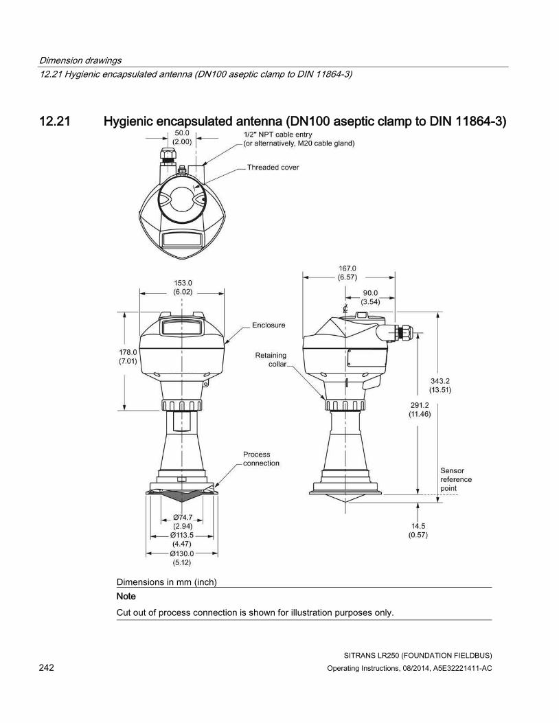
Dimension drawings
12.21 Hygienic encapsulated antenna (DN100 aseptic clamp to DIN 11864-3)
SITRANS LR250 (FOUNDATION FIELDBUS)
242 Operating Instructions, 08/2014, A5E32221411-AC
12.21 Hygienic encapsulated antenna (DN100 aseptic clamp to DIN 11864-3)
Dimensions in mm (inch)
Note
Cut out of process connection is shown for illustration purposes only.

Dimension drawings
12.22 Hygienic encapsulated antenna (Tuchenhagen Type N)
SITRANS LR250 (FOUNDATION FIELDBUS)
Operating Instructions, 08/2014, A5E32221411-AC 243
12.22 Hygienic encapsulated antenna (Tuchenhagen Type N)
Dimensions in mm (inch)

Dimension drawings
12.23 Hygienic encapsulated antenna (Tuchenhagen Type F)
SITRANS LR250 (FOUNDATION FIELDBUS)
244 Operating Instructions, 08/2014, A5E32221411-AC
12.23 Hygienic encapsulated antenna (Tuchenhagen Type F)
Dimensions in mm (inch)

Dimension drawings
12.24 Threaded PVDF antenna
SITRANS LR250 (FOUNDATION FIELDBUS)
Operating Instructions, 08/2014, A5E32221411-AC 245
12.24 Threaded PVDF antenna

Dimension drawings
12.25 Threaded connection markings
SITRANS LR250 (FOUNDATION FIELDBUS)
246 Operating Instructions, 08/2014, A5E32221411-AC
Threaded PVDF antenna dimensions
Nominal antenna size
Antenna O.D. Height to sensor reference point a)
Beam angle b) Measurement range
50 mm (2") 49.5 mm (1.94") 121 mm (4.76") 19 degrees 10 m (32.8 ft)c)
a) Height from bottom of antenna to sensor reference point as shown: see dimension drawing.
b) -3dB in the direction of the polarization axis. See Polarization reference point (Page 31) for an illustration.
c) 20m when installed in stillpipe.
12.25 Threaded connection markings
With the exception of the threaded PVDF antenna, threaded connection markings are found on the flat face/faces of the process connection. Serial number: a unique number allotted to each process connection, including the date of manufacture (MMDDYY) followed by a number from 001 to 999, (indicating the sequential unit produced).

Dimension drawings
12.26 Raised-Face flange per EN 1092-1 for flanged horn antenna
SITRANS LR250 (FOUNDATION FIELDBUS)
Operating Instructions, 08/2014, A5E32221411-AC 247
12.26 Raised-Face flange per EN 1092-1 for flanged horn antenna
Stainless steel or optional alloy N06022/2.4602 (Hastelloy® C-22)
① angle of adjacent bolt holes ⑥ bolt hole circle diameter
② bolt hole diameter ⑦ facing height
③ bolt hole circle diameter ⑧ facing diameter
④ waveguide mounting hole ⑨ sensor reference point
⑤ Flange O.D. ⑩ thickness

Dimension drawings
12.26 Raised-Face flange per EN 1092-1 for flanged horn antenna
SITRANS LR250 (FOUNDATION FIELDBUS)
248 Operating Instructions, 08/2014, A5E32221411-AC
Raised-Face flange dimensions
Pipe size Flange bolt hole pattern
⑤
Flange O.D. (mm)
③
Bolt hole circle Ø (mm)
②
Bolt hole Ø (mm)
No. of bolts ①
Angle of adjacent bolt holes
⑧
Facing Ø (mm)
⑩
Thickness (mm)
DN50 PN10/PN16 165 125 18 4 90 102 18
DN80 PN10/PN16 200 160 18 8 45 138 20
DN100 PN10/PN16 220 180 18 8 45 158 20
DN150 PN10/PN16 285 240 22 8 45 212 22
DN50 PN25/PN40 165 160 18 4 90 138 20
DN80 PN25/PN40 200 160 18 8 45 138 24
DN100 PN25/PN40 235 190 22 8 45 162 24
DN150 PN25/PN40 300 250 26 8 45 218 28
Raised-Face flange markings
Blind Flange Markings (Optional Manufacturer’s Logo [optional]; Flange Standard; Nominal Size; Material; Heat
Code)
Machining Identification Welded Assembly Identification a)
Serial no. Logo Flange series Flange series
Heat Code no.
Facing
Manufacturer’s logo; EN 1092-1 05 ‘B1’; ‘DN50’ ‘PN16’ ‘1.4404 or 1.4435’ A1B2C3
mmddyyxxx
xxxxx xxxxx A1B2C3 RF
a) When flange material is alloy N06022/2.4602, additional material and heat code identification is provided.
The flange markings are located around the outside edge of the flange.
Serial number: a unique number allotted to each flange, including the date of manufacture (MMDDYY) followed by a number from 001 to 999 (indicating the sequential unit produced).
Flange series: the Siemens Milltronics drawing identification.
Heat code: a flange material batch code identification.

Dimension drawings
12.27 Raised-Face flange per EN 1092-1 for flanged encapsulated antenna
SITRANS LR250 (FOUNDATION FIELDBUS)
Operating Instructions, 08/2014, A5E32221411-AC 249
12.27 Raised-Face flange per EN 1092-1 for flanged encapsulated antenna
Stainless steel
① angle of adjacent bolt holes ⑤ flange O.D.
② bolt hole diameter ⑥ facing height
③ bolt hole circle diameter ⑦ facing diameter
④ antenna ⑧ flange thickness

Dimension drawings
12.27 Raised-Face flange per EN 1092-1 for flanged encapsulated antenna
SITRANS LR250 (FOUNDATION FIELDBUS)
250 Operating Instructions, 08/2014, A5E32221411-AC
Raised-Face flange dimensions
Pipe size Flange class ⑤
Flange O.D. [mm (inch)]
③ Bolt hole circle Ø [mm (inch)]
② Bolt hole Ø [mm (inch)]
No. of bolt holes
① Angle of adjacent bolt holes
⑦
Facing Ø [mm (inch)]
⑨
Flange thickness [mm (inch)]
⑥
Flange facing thickness
[mm (inch)]
2" 150 LB 152 (5.98)
120.7 (4.75)
19 (0.75) 4 90 92.1 (3.63)
20.6 (0.81)
1.5 (0.06)
3" 190 (7.48)
152.4 (6.00)
127 (5.00) 25.9 (1.02)
2 (0.08)
4" 230 (9.06)
190.5 (7.50)
8 45 157.2 (6.19)
2 (0.08)
6" 280 (11.02)
241.3 (9.50)
22.2 (0.87)
215.9 (8.50)
26.9 (1.06)
1.5 (0.06)
DN50 PN10/16 155 (6.10)
125 (4.92) 18 (0.71) 4 90 102 (4.02) 18 (0.71) 2 (0.08)
DN80 200 (7.87)
160 (6.30) 8 45 138 (5.43) 20 (0.79)
2 (0.08)
DN100 220 (8.66)
180 (7.09) 158 (6.22) 2 (0.08)
DN150 285 (11.22)
240 (9.45) 22 (0.87) 212 (8.35) 22 (0.87) 2 (0.08)
50A 10K 155 (6.10)
120 (4.72) 19 (0.75) 4 90 96 (3.78) 16 (0.63) 2 (0.08)
80A 185 (7.28)
150 (5.91) 8 45 126 (4.96) 18 (0.71)
2 (0.08)
100A 210 (8.27)
175 (6.89) 151 (5.94) 2 (0.08)
150A 280 (11.02)
240 (9.45) 23 (0.91) 212 (8.35) 22 (0.87) 2 (0.08)

Dimension drawings
12.27 Raised-Face flange per EN 1092-1 for flanged encapsulated antenna
SITRANS LR250 (FOUNDATION FIELDBUS)
Operating Instructions, 08/2014, A5E32221411-AC 251
Raised-Face flange markings
Blind Flange Markings (Optional Manufacturer’s Logo [optional]; Flange Standard; Nominal Size; Material; Heat
Code)
Machining Identification Welded Assembly Identification
Serial no. Logo Flange series Flange series
Heat Code no.
Facing
Manufacturer’s logo; EN 1092-1 05 ‘B1’; ‘DN50’ ‘PN16’ ‘1.4404 or 1.4435’ A1B2C3
mmddyyxxx
xxxxx xxxxx A1B2C3 RF
The flange markings are located around the outside edge of the flange.
Serial number: a unique number allotted to each flange, including the date of manufacture (MMDDYY) followed by a number from 001 to 999 (indicating the sequential unit produced).
Flange series: the Siemens Milltronics drawing identification.
Heat code: a flange material batch code identification.

Dimension drawings
12.28 Flat-Face flange
SITRANS LR250 (FOUNDATION FIELDBUS)
252 Operating Instructions, 08/2014, A5E32221411-AC
12.28 Flat-Face flange
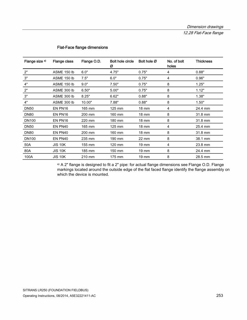
Dimension drawings
12.28 Flat-Face flange
SITRANS LR250 (FOUNDATION FIELDBUS)
Operating Instructions, 08/2014, A5E32221411-AC 253
Flat-Face flange dimensions
Flange size a) Flange class Flange O.D. Bolt hole circle Ø
Bolt hole Ø No. of bolt holes
Thickness
2" ASME 150 lb 6.0" 4.75" 0.75" 4 0.88"
3" ASME 150 lb 7.5" 6.0" 0.75" 4 0.96"
4" ASME 150 lb 9.0" 7.50" 0.75" 8 1.25"
2" ASME 300 lb 6.50" 5.00" 0.75" 8 1.12"
3" ASME 300 lb 8.25" 6.62" 0.88" 8 1.38"
4" ASME 300 lb 10.00" 7.88" 0.88" 8 1.50"
DN50 EN PN16 165 mm 125 mm 18 mm 4 24.4 mm
DN80 EN PN16 200 mm 160 mm 18 mm 8 31.8 mm
DN100 EN PN16 220 mm 180 mm 18 mm 8 31.8 mm
DN50 EN PN40 165 mm 125 mm 18 mm 4 25.4 mm
DN80 EN PN40 200 mm 160 mm 18 mm 8 31.8 mm
DN100 EN PN40 235 mm 190 mm 22 mm 8 38.1 mm
50A JIS 10K 155 mm 120 mm 19 mm 4 23.8 mm
80A JIS 10K 185 mm 150 mm 19 mm 8 24.4 mm
100A JIS 10K 210 mm 175 mm 19 mm 8 28.5 mm
a) A 2" flange is designed to fit a 2" pipe: for actual flange dimensions see Flange O.D. Flange markings located around the outside edge of the flat faced flange identify the flange assembly on which the device is mounted.

Dimension drawings
12.28 Flat-Face flange
SITRANS LR250 (FOUNDATION FIELDBUS)
254 Operating Instructions, 08/2014, A5E32221411-AC
Flat-Face flange markings
Flat Face Flange Identification Welded Assembly Identification
Serial No. Logo Flange series Material Heat code
Flange series
Heat code no. Series Nominal size
MMDDYYXXX
25556 2 150 316L/ 1.4404 or 316L/ 1.4435
A1B2C3 25546 A1B2C3
DN80 PN16
Serial number: A unique number allotted to each flange, including the date of manufacture (MMDDYY) followed by a number from 001 to 999 (indicating the sequential unit produced).
Flange series: The Siemens Milltronics drawing identification.
Nominal size: The flange size followed by the hole pattern for a particular flange class. For example:
• A 2 inch ASME B16.5 150 lb class flange (North America)
• A DN80 EN 1092-1 PN16 class flange (Europe)
Material: The basic flange material (AISI or EU material designation). North American material codes are followed by European ones. For example, material designation 316L/1.4404.
Heat code: A flange material batch code identification.

Dimension drawings
12.29 Aseptic/hygienic flange DN50, DN80, DN100 for DIN 11864-2
SITRANS LR250 (FOUNDATION FIELDBUS)
Operating Instructions, 08/2014, A5E32221411-AC 255
12.29 Aseptic/hygienic flange DN50, DN80, DN100 for DIN 11864-2
Aseptic/hygienic flange DN50
Dimensions in mm (inch)

Dimension drawings
12.29 Aseptic/hygienic flange DN50, DN80, DN100 for DIN 11864-2
SITRANS LR250 (FOUNDATION FIELDBUS)
256 Operating Instructions, 08/2014, A5E32221411-AC
Aseptic/hygienic flange DN80
Dimensions in mm (inch)

Dimension drawings
12.29 Aseptic/hygienic flange DN50, DN80, DN100 for DIN 11864-2
SITRANS LR250 (FOUNDATION FIELDBUS)
Operating Instructions, 08/2014, A5E32221411-AC 257
Aseptic/hygienic flange DN100
Dimensions in mm (inch)

Dimension drawings
12.30 Process connection tag (pressure rated versions)
SITRANS LR250 (FOUNDATION FIELDBUS)
258 Operating Instructions, 08/2014, A5E32221411-AC
12.30 Process connection tag (pressure rated versions)
For pressure-rated versions only, the process connection label lists the following information:
Process connection tag (pressure rated versions)
Item Sample Text Comments/Explanation
SERIAL # GYZ / 00000000 Pressure Boundary Assembly
NOMINAL PIPE SIZE (DN) 4 INCH / 100mm Nominal Pipe Size
INSTRUMENT MAWP (PS) 11.0 BAR Maximum Allowable Working Pressure at Design Temperature for the device
DESIGN TEMP. (TS) 200 ºC Maximum Allowable Working Temperature
MINIMUM PROCESS 15.9 BAR AT 40 ºC Minimum Wetted Process Conditions
TEST PRESSURE (PT) 22.7 BAR Production Test Pressure
TEST DATE 10/11/11 Date of Pressure Test (Year/Month/Day)
CONNECTION SERIES ASME B16.5 Flange Series: dimensional pattern based on ASME B16.5 flange standards
PROCESS SERIES 25546 Pressure Tag Family Series
WETTED NON-METALLICS TFM Antenna Emitter
WETTED METALLICS 316L Process Connection Material(s)
WETTED SEALS FKM Seal Material(s)
● Minimum Wetted Process Conditions: the minimum pressure and temperature to which the device assembly may be exposed in the process, and continue to provide a pressure-retaining function.
● Pressure Tag Family Series: the identification number used to indicate specific process connection information relating to operating conditions.
● For Flanged encapsulated antenna: this information is laser-etched on antenna body
BACK FACE
Sample Text Comments/Explanation
CRN 0Fxxxxx.5 Canadian Registration Number (CRN)

SITRANS LR250 (FOUNDATION FIELDBUS)
Operating Instructions, 08/2014, A5E32221411-AC 259
Appendix A: Technical reference A
Note
Where a number follows the parameter name [for example, Master Reset (4.1.)] this is the parameter access number via the handheld programmer. See Parameter Reference (Page 139) for a complete list of parameters.
A.1 Principles of operation
SITRANS LR250 is a 2-wire 25 GHz pulse radar level transmitter for continuous monitoring of liquids and slurries. (The microwave output level is significantly less than that emitted from cellular phones.) Radar level measurement uses the time of flight principle to determine distance to a material surface. The device transmits a signal and waits for the return echo. The transit time is directly proportional to the distance from the material.
Pulse radar uses polarized electromagnetic waves. Microwave pulses are emitted from the antenna at a fixed repetition rate, and reflect off the interface between two materials with different dielectric constants (the atmosphere and the material being monitored).
Electromagnetic wave propagation is virtually unaffected by temperature or pressure changes, or by changes in the vapor levels inside a vessel. Electromagnetic waves are not attenuated by dust.
SITRANS LR250 consists of an enclosed electronic circuit coupled to an antenna and process connection. The electronic circuit generates a radar signal (25 GHz) that is directed to the antenna.
The signal is emitted from the antenna, and the reflected echoes are digitally converted to an echo profile. The profile is analyzed to determine the distance from the material surface to the sensor reference point. See Dimension drawings (Page 215). This distance is used as a basis for the display of material level and mA output.

Appendix A: Technical reference
A.2 Echo processing
SITRANS LR250 (FOUNDATION FIELDBUS)
260 Operating Instructions, 08/2014, A5E32221411-AC
A.2 Echo processing
A.2.1 Process Intelligence
The signal processing technology embedded in Siemens radar level devices is known as Process Intelligence.
Process intelligence provides high measurement reliability regardless of the dynamically changing conditions within the vessel being monitored. The embedded Process Intelligence dynamically adjusts to the constantly changing material surfaces within these vessels.
Process Intelligence is able to differentiate between the true microwave reflections from the surface of the material and unwanted reflections being returned from obstructions such as seam welds or supports within a vessel. The result is repeatable, fast and reliable measurement. This technology was developed as result of field data gained over some twenty years from more than 1,000,000 installations in many industries around the world.
Higher order mathematical techniques and algorithms are used to provide intelligent processing of microwave reflection profiles. This "knowledge based" technique produces superior performance and reliability.

Appendix A: Technical reference
A.2 Echo processing
SITRANS LR250 (FOUNDATION FIELDBUS)
Operating Instructions, 08/2014, A5E32221411-AC 261
A.2.2 Echo Selection
Time Varying Threshold (TVT)
A Time Varying Threshold (TVT) hovers above the echo profile to screen out unwanted reflections (false echoes).
In most cases the material echo is the only one which rises above the default TVT.
In a vessel with obstructions, a false echo may occur. See Auto False Echo Suppression (Page 265) for more details.
① default TVT
② echo profile
③ material level
④ echo marker
The device characterizes all echoes that rise above the TVT as potential good echoes. Each peak is assigned a rating based on its strength, area, height above the TVT, and reliability, amongst other characteristics.
Algorithm (2.5.7.1.)
The true echo is selected based on the setting for the Echo selection algorithm. Options are true First Echo, Largest Echo, or best of First and Largest.

Appendix A: Technical reference
A.2 Echo processing
SITRANS LR250 (FOUNDATION FIELDBUS)
262 Operating Instructions, 08/2014, A5E32221411-AC
Position Detect (2.5.7.2.)
The echo position detection algorithm determines which point on the echo will be used to calculate the precise time of flight, and calculates the range using the calibrated propagation velocity [see Propagation Factor (2.5.3.) for values]. There are three options:
● Center
● Hybrid (Center and CLEF)
● CLEF (Constrained Leading Edge Fit)
Center
Uses center of the echo.
Hybrid
Uses the Center algorithm for the top part of the vessel, and the CLEF algorithm for the part nearest the vessel bottom, according to the setting for CLEF range.
CLEF (Constrained Leading Edge Fit)
● Uses the leading edge of the echo.
● Is used mainly to process the echo from materials with a low dK value.
In an almost empty flat-bottomed vessel, a low dK material may reflect an echo weaker than the echo from the vessel bottom. The echo profile shows these echoes merging. The device may then report a material level equal to or lower than empty.
The CLEF algorithm enables the device to report the level correctly.
Example: CLEF off: Position set to Hybrid
Vessel height: 1.5 m; CLEF range set to 0 (Center algorithm gives the same result.)

Appendix A: Technical reference
A.2 Echo processing
SITRANS LR250 (FOUNDATION FIELDBUS)
Operating Instructions, 08/2014, A5E32221411-AC 263
① default TVT
② material echo
③ vessel bottom echo selected
④ echo marker
Example: CLEF enabled
Vessel height: 1.5 m; CLEF range set to 0.5 m
① default TVT
② material echo selected
③ vessel bottom echo
④ echo marker

Appendix A: Technical reference
A.2 Echo processing
SITRANS LR250 (FOUNDATION FIELDBUS)
264 Operating Instructions, 08/2014, A5E32221411-AC
A.2.3 CLEF Range
CLEF Range (2.5.7.4.) is referenced from Low Calibration Point (process empty level). When the Hybrid algorithm is selected in Position Detect (2.5.7.2.), the CLEF algorithm will be applied up to the limit of CLEF Range. Above this limit the Center algorithm will be applied.
① CLEF Range
② (Center algorithm applied)
③ High Calibration Point (process full level)
④ Sensor reference point
⑤ Low Calibration Point (process empty level)
A.2.4 Measurement Response
Note
Units are defined in Units (2.3.1.) and are in meters by default.
Response Rate (2.3.8.1.) limits the maximum rate at which the display and output respond to changes in the measurement. There are three preset options: slow, medium, and fast.
Once the real process fill/empty rate (m/s by default) is established, a response rate can be selected that is slightly higher than the application rate. Response Rate automatically adjusts the filters that affect the output response rate.
Note
Changing Response Rate resets Fill Rate per Minute (2.3.8.2.), Empty Rate per Minute (2.3.8.3.), and Shots (2.5.6.).
Response Rate (2.3.8.1)
Fill Rate (2.3.8.2)/Empty Rate (2.3.8.3)
* Slow 0.1 m/min (0.32 ft/min) 25
Medium 1.0 m/min (3.28 ft.min) 10
Fast 10.0 m/min (32.8 ft/min) 5

Appendix A: Technical reference
A.2 Echo processing
SITRANS LR250 (FOUNDATION FIELDBUS)
Operating Instructions, 08/2014, A5E32221411-AC 265
A.2.5 Echo Threshold
Confidence (2.5.9.1.) describes the quality of an echo. Higher values represent higher quality. Echo Threshold (2.5.7.3.) defines the minimum confidence value required for an echo to be accepted as valid and evaluated.
A.2.6 Echo Lock
If the echo selected by Algorithm is within the Echo Lock window, the window is centered about the echo, which is used to derive the measurement. In radar applications, two measurement verification options are used:
Lock Off
SITRANS LR250 responds immediately to a new selected echo (within the restrictions set by the Maximum Fill / Empty Rate), but measurement reliability is affected.
Material Agitator
A new measurement outside the Echo Lock Window must meet the sampling criteria before the window will move to include it. The other available options, Maximum Verification and Total Lock are not recommended for radar.
A.2.7 Auto False Echo Suppression
Note
• For detailed instructions on using this feature via AMS see TVT (time varying threshold) (Page 96).
• For detailed instructions on using this feature via the handheld programmer see Auto False Echo Suppression (2.5.10.1.).
Auto False Echo Suppression is designed to learn a specific environment (for example, a particular vessel with known obstructions), and in conjunction with Auto False Echo Suppression Range to remove false echoes appearing in front of the material echo.
The material level should be below all known obstructions at the moment when Auto False Echo Suppression learns the echo profile. Ideally the vessel should be empty or almost empty, and if an agitator is present, it should be running.
The device learns the echo profile over the whole measurement range and the TVT is shaped around all echoes present at that moment.

Appendix A: Technical reference
A.2 Echo processing
SITRANS LR250 (FOUNDATION FIELDBUS)
266 Operating Instructions, 08/2014, A5E32221411-AC
Auto False Echo Suppression Range (2.5.10.2.)
Auto False Echo Suppression Range specifies the range within which the learned TVT is applied. Default TVT is applied over the remainder of the range.
The learned TVT screens out the false echoes caused by obstructions. The default TVT allows the material echo to rise above it.
Auto False Echo Suppression Range must be set to a distance shorter than the distance to the material level when the environment was learned, to avoid the material echo being screened out.
Example before Auto False Echo Suppression
① Default TVT ⑤ High calibration point = 0
② False echo ⑥ Obstruction at 1.3. m
③ Material echo ⑦ Material level at 3.2 m
④ Sensor reference point

Appendix A: Technical reference
A.2 Echo processing
SITRANS LR250 (FOUNDATION FIELDBUS)
Operating Instructions, 08/2014, A5E32221411-AC 267
Example after Auto False Echo Suppression
Auto False Echo Suppression Range set to 2 m
① Learned TVT ④ Default TVT
② False echo ⑤ Material echo
③ Auto False Echo Suppression Range ⑥ Echo marker
A.2.8 Measurement Range
Near Range (2.5.1.)
Near Range programs SITRANS LR250 to ignore the zone in front of the antenna. The default blanking distance is 50 mm (1.97") from the end of the antenna.
Near Range allows you to increase the blanking value from its factory default. But Auto False Echo Suppression (2.5.10.1.) is generally recommended in preference to extending the blanking distance from factory values.
Far Range (2.5.2.)
Far Range can be used in applications where the base of the vessel is conical or parabolic. A reliable echo may be available below the vessel empty distance, due to an indirect reflection path.
Increasing Far Range to 30% or 40% can provide stable empty vessel readings.
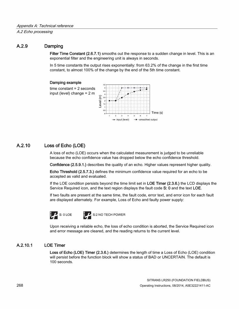
Appendix A: Technical reference
A.2 Echo processing
SITRANS LR250 (FOUNDATION FIELDBUS)
268 Operating Instructions, 08/2014, A5E32221411-AC
A.2.9 Damping
Filter Time Constant (2.6.7.1) smooths out the response to a sudden change in level. This is an exponential filter and the engineering unit is always in seconds.
In 5 time constants the output rises exponentially: from 63.2% of the change in the first time constant, to almost 100% of the change by the end of the 5th time constant.
Damping example
time constant = 2 seconds input (level) change = 2 m
A.2.10 Loss of Echo (LOE)
A loss of echo (LOE) occurs when the calculated measurement is judged to be unreliable because the echo confidence value has dropped below the echo confidence threshold.
Confidence (2.5.9.1.) describes the quality of an echo. Higher values represent higher quality.
Echo Threshold (2.5.7.3.) defines the minimum confidence value required for an echo to be accepted as valid and evaluated.
If the LOE condition persists beyond the time limit set in LOE Timer (2.3.6.) the LCD displays the Service Required icon, and the text region displays the fault code S: 0 and the text LOE.
If two faults are present at the same time, the fault code, error text, and error icon for each fault are displayed alternately. For example, Loss of Echo and faulty power supply:
Upon receiving a reliable echo, the loss of echo condition is aborted, the Service Required icon and error message are cleared, and the reading returns to the current level.
A.2.10.1 LOE Timer
Loss of Echo (LOE) Timer (2.3.6.) determines the length of time a Loss of Echo (LOE) condition will persist before the function block will show a status of BAD or UNCERTAIN. The default is 100 seconds.

Appendix A: Technical reference
A.3 Maximum Process Temperature Chart
SITRANS LR250 (FOUNDATION FIELDBUS)
Operating Instructions, 08/2014, A5E32221411-AC 269
A.3 Maximum Process Temperature Chart
WARNING
Exceeded maximum internal and process temperatures
Danger of device malfunction
• Internal temperature must not exceed +80 ° C (+176 °F).
• Process temperature must not exceed limits specified by the antenna type.
Note
• The chart below is for guidance only.
• The chart does not represent every possible process connection arrangement. For example, it will NOT apply if you are mounting SITRANS LR250 directly on a metallic vessel surface.
• The chart does not take into consideration heating from direct sunlight exposure.
Maximum Process Temperatures versus allowable ambient
① Internal enclosure temperature
② Ambient temperature
③ Process temperature (at process connection)
Where the chart does not apply, please use your own judgement regarding the use of SITRANS LR250.
If the internal temperature exceeds the maximum allowable limit, a sun shield or a longer nozzle may be required.
See Minimum Value (3.3.1.) and Maximum Value (3.3.2.) to monitor the Internal Temperature.

Appendix A: Technical reference
A.4 Process Pressure/Temperature derating curves
SITRANS LR250 (FOUNDATION FIELDBUS)
270 Operating Instructions, 08/2014, A5E32221411-AC
A.4 Process Pressure/Temperature derating curves
WARNING
Exceeded maximum permissible operating pressure
Danger of injury or poisoning.
The maximum permissible operating pressure depends on the device version. The device can be damaged if the operating pressure is exceeded. Hot, toxic and corrosive process media could be released.
• Make sure that the device is suitable for the maximum permissible operating pressure of your system.
DANGER
Pressure applications
Danger to personnel, system and environment will result from improper disassembly.
• Never attempt to loosen, remove, or disassemble process connection while vessel contents are under pressure.
WARNING
Pressure applications
Danger to personnel, system and environment can result from improper installation.
• Improper installation may result in loss of process pressure.
WARNING
Unsuitable connecting parts
Danger of injury or poisoning.
In case of improper mounting hot, toxic and corrosive process media could be released at the connections.
• Ensure that connecting parts (such as flange gaskets and bolts) are suitable for connection and process media.
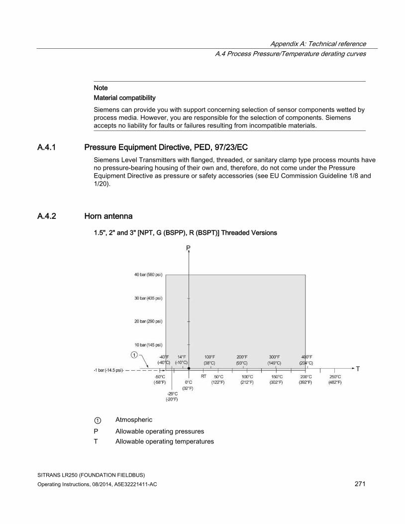
Appendix A: Technical reference
A.4 Process Pressure/Temperature derating curves
SITRANS LR250 (FOUNDATION FIELDBUS)
Operating Instructions, 08/2014, A5E32221411-AC 271
Note
Material compatibility
Siemens can provide you with support concerning selection of sensor components wetted by process media. However, you are responsible for the selection of components. Siemens accepts no liability for faults or failures resulting from incompatible materials.
A.4.1 Pressure Equipment Directive, PED, 97/23/EC
Siemens Level Transmitters with flanged, threaded, or sanitary clamp type process mounts have no pressure-bearing housing of their own and, therefore, do not come under the Pressure Equipment Directive as pressure or safety accessories (see EU Commission Guideline 1/8 and 1/20).
A.4.2 Horn antenna
1.5", 2" and 3" [NPT, G (BSPP), R (BSPT)] Threaded Versions
① Atmospheric
P Allowable operating pressures
T Allowable operating temperatures

Appendix A: Technical reference
A.4 Process Pressure/Temperature derating curves
SITRANS LR250 (FOUNDATION FIELDBUS)
272 Operating Instructions, 08/2014, A5E32221411-AC
A.4.3 Flanged horn antenna
JIS B 2220, 10K: 50A, 80A, and 100A
① Atmospheric
P Allowable operating pressures
T Allowable operating temperatures
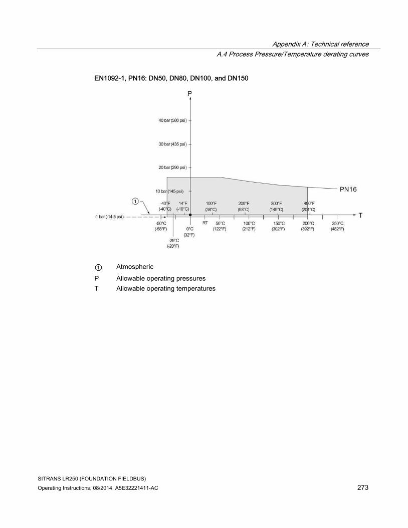
Appendix A: Technical reference
A.4 Process Pressure/Temperature derating curves
SITRANS LR250 (FOUNDATION FIELDBUS)
Operating Instructions, 08/2014, A5E32221411-AC 273
EN1092-1, PN16: DN50, DN80, DN100, and DN150
① Atmospheric
P Allowable operating pressures
T Allowable operating temperatures

Appendix A: Technical reference
A.4 Process Pressure/Temperature derating curves
SITRANS LR250 (FOUNDATION FIELDBUS)
274 Operating Instructions, 08/2014, A5E32221411-AC
EN1092-1, PN40: DN50, DN80, DN100, and DN150
① Atmospheric
P Allowable operating pressures
T Allowable operating temperatures

Appendix A: Technical reference
A.4 Process Pressure/Temperature derating curves
SITRANS LR250 (FOUNDATION FIELDBUS)
Operating Instructions, 08/2014, A5E32221411-AC 275
ASME B16.5, Class 150: 2", 3", and 4" NPS
① Atmospheric
P Allowable operating pressures
T Allowable operating temperatures

Appendix A: Technical reference
A.4 Process Pressure/Temperature derating curves
SITRANS LR250 (FOUNDATION FIELDBUS)
276 Operating Instructions, 08/2014, A5E32221411-AC
ASME B16.5, Class 300: 2", 3", and 4" NPS
① Atmospheric
P Allowable operating pressures
T Allowable operating temperatures

Appendix A: Technical reference
A.4 Process Pressure/Temperature derating curves
SITRANS LR250 (FOUNDATION FIELDBUS)
Operating Instructions, 08/2014, A5E32221411-AC 277
A.4.4 Flanged encapsulated antenna
ASME B16.5, Class 150: 2", 3", 4", and 6" NPS
① Atmospheric
P Allowable operating pressures
T Allowable operating temperatures
JIS B 2220, 10K: 50A, 80A, 100A, and 150A
① Atmospheric
P Allowable operating pressures
T Allowable operating temperatures

Appendix A: Technical reference
A.4 Process Pressure/Temperature derating curves
SITRANS LR250 (FOUNDATION FIELDBUS)
278 Operating Instructions, 08/2014, A5E32221411-AC
EN1092-1, PN10/16: DN50, DN80, DN100, and DN150
① Atmospheric
P Allowable operating pressures
T Allowable operating temperatures

Appendix A: Technical reference
A.4 Process Pressure/Temperature derating curves
SITRANS LR250 (FOUNDATION FIELDBUS)
Operating Instructions, 08/2014, A5E32221411-AC 279
A.4.5 PVDF antenna
ASME B1.20.1 2" NPT, EN ISO 228-1 2" G (BSPP), EN 10226-1 2" R (BSPT)
① Atmospheric
P Allowable operating pressures
T Allowable operating temperatures

Appendix A: Technical reference
A.4 Process Pressure/Temperature derating curves
SITRANS LR250 (FOUNDATION FIELDBUS)
280 Operating Instructions, 08/2014, A5E32221411-AC
A.4.6 Hygienic encapsulated antenna
DIN 11851 Sanitary/Hygienic nozzle/slotted nut: DN50, DN80, and DN100
DIN 11864-1 Aseptic/Hygienic nozzle/slotted nut: DN50, DN80, and DN100
① Atmospheric
P Allowable operating pressures
T Allowable operating temperatures

Appendix A: Technical reference
A.4 Process Pressure/Temperature derating curves
SITRANS LR250 (FOUNDATION FIELDBUS)
Operating Instructions, 08/2014, A5E32221411-AC 281
DIN 11864-2 Aseptic/Hygienic flanged: DN50, DN80, and DN100
① Atmospheric
P Allowable operating pressures
T Allowable operating temperatures
Note
For pressure applications, all attachment hardware must be suitably rated.
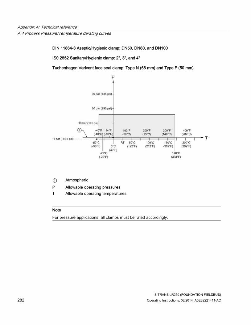
Appendix A: Technical reference
A.4 Process Pressure/Temperature derating curves
SITRANS LR250 (FOUNDATION FIELDBUS)
282 Operating Instructions, 08/2014, A5E32221411-AC
DIN 11864-3 Aseptic/Hygienic clamp: DN50, DN80, and DN100
IS0 2852 Sanitary/Hygienic clamp: 2", 3", and 4"
Tuchenhagen Varivent face seal clamp: Type N (68 mm) and Type F (50 mm)
① Atmospheric
P Allowable operating pressures
T Allowable operating temperatures
Note
For pressure applications, all clamps must be rated accordingly.

SITRANS LR250 (FOUNDATION FIELDBUS)
Operating Instructions, 08/2014, A5E32221411-AC 283
Appendix B: Communications via Foundation Fieldbus B
SITRANS LR250 (Foundation Fieldbus) is an FF (H1) device of Class 31PS, and 32L. It supports publish and subscribe functionality as well as Backup LAS functionality. The full range of SITRANS LR250 functions is available only over an FF network.
Foundation Fieldbus (FF) is an open industrial protocol. Full details about FF can be obtained from: Foundation Fieldbus (http://www.fieldbus.org/)
For details on the use of Foundation Fieldbus protocol with Siemens FF level instruments, see manual Foundation Fieldbus for Level Instruments (7ML19985MP01). The manual is available on the CD of Siemens manuals, included in the box with your Siemens level instrument, or for other Siemens level measurement manuals, go to:
Siemens level (http://www.siemens.com/level)
Look under Level Measurement.
B.1 Field Communicator 375 (F375)
This device supports Field Communicator 375 (FC375). The FC375 menu structure is very similar to the menu structure for AMS Device Manager [see AMS Menu Structure (Page 75).]

Appendix B: Communications via Foundation Fieldbus
B.1 Field Communicator 375 (F375)
SITRANS LR250 (FOUNDATION FIELDBUS)
284 Operating Instructions, 08/2014, A5E32221411-AC

SITRANS LR250 (FOUNDATION FIELDBUS)
Operating Instructions, 08/2014, A5E32221411-AC 285
Appendix C: Certificates and support C C.1 Certificates
Certificates can be downloaded from our website at:
Product page (http://www.siemens.com/LR250).
C.2 Technical support
If you have any technical questions about the device described in these Operating Instructions and do not find the right answers, you can contact Customer Support:
● Via the Internet using the Support Request: Support request (http://www.siemens.com/automation/support-request)
● Via Phone:
– Europe: +49 (0)911 895 7222
– America: +1 423 262 5710
– Asia-Pacific: +86 10 6475 7575
Further information about our technical support is available on the Internet at Technical support (http://support.automation.siemens.com/WW/view/en/16604318)
Service & Support on the Internet
In addition to our documentation, we offer a comprehensive knowledge base online on the Internet at:
Service & Support (http://www.siemens.com/automation/service&support)
There you will find:
● The latest product information, FAQs, downloads, tips and tricks.
● Our newsletter, providing you with the latest information about your products.
● Our bulletin board, where users and specialists share their knowledge worldwide.
● You can find your local contact partner for Industry Automation and Drives Technologies in our partner database.
● Information about field service, repairs, spare parts and lots more under "Services."

Appendix C: Certificates and support
C.2 Technical support
SITRANS LR250 (FOUNDATION FIELDBUS)
286 Operating Instructions, 08/2014, A5E32221411-AC
Additional Support
Please contact your local Siemens representative and offices if you have additional questions about the device
Find your contact partner at:
Local contact person (http://www.siemens.com/automation/partner)

SITRANS LR250 (FOUNDATION FIELDBUS)
Operating Instructions, 08/2014, A5E32221411-AC 287
List of abbreviations 13 Short form Long form Description Units
3-A 3-A Sanitary Standards, Inc.
AIFB Analog Input Function Block
CE / FM / CSA Conformité Européene / Factory Mutual / Canadian Standards Association
safety approval
Ci Internal capacitance F
D/A Dialog to analog
DCS Distributed Control System control room apparatus
dK dielectric constant
EDD Electronic Device Description
EHEDG European Hygienic Engineering Design Group
FEA Flanged encapsulated antenna
FDA Food and Drug Administration
HEA Hygienic encapsulated antenna
Ii Input current mA
Io Output current mA
IS Intrinsically Safe safety approval
Li Internal inductance mH
mH milliHenry 10-3 H
μF microFarad 10-6 F
μs microsecond 10-6 s
PED Pressure Equipment Directive safety approval
pF pico Farads 10-12 F
ppm parts per million
PV Primary Variable measured value
PVDF Polyvinylidene fluoride
SELV Safety extra low voltage
SV Secondary Variable equivalent value
TB Transducer Block
TVT Time Varying Threshold sensitivity threshold
TFM1600 PTFE Modified PTFE polytetrafluoroethylene with perfluoropropyl vinyl ether (PPVE) modifier
Ui Input voltage V
Uo Output voltage V

List of abbreviations
SITRANS LR250 (FOUNDATION FIELDBUS)
288 Operating Instructions, 08/2014, A5E32221411-AC

SITRANS LR250 (FOUNDATION FIELDBUS)
Operating Instructions, 08/2014, A5E32221411-AC 289
LCD menu structure 14
Note
• In Navigation mode, ARROW keys ( ) navigate the menu in the direction of
the arrow. See Parameter Reference (Page 139) for detailed information and
instructions.

LCD menu structure
SITRANS LR250 (FOUNDATION FIELDBUS)
290 Operating Instructions, 08/2014, A5E32221411-AC

LCD menu structure
SITRANS LR250 (FOUNDATION FIELDBUS)
Operating Instructions, 08/2014, A5E32221411-AC 291

LCD menu structure
SITRANS LR250 (FOUNDATION FIELDBUS)
292 Operating Instructions, 08/2014, A5E32221411-AC
SITRANS LR250 (FOUNDATION FIELDBUS)
Operating Instructions, 08/2014, A5E32221411-AC 293
Glossary
accuracy
degree of conformity of a measure to a standard or a true value.
algorithm
a prescribed set of well-defined rules or processes for the solution of a problem in a finite number of steps.
ambient temperature
the temperature of the surrounding air that comes in contact with the enclosure of the device.
antenna
an aerial which sends out and receives a signal in a specific direction. There are four basic types of antenna in radar level measurement, horn, parabolic, rod, and waveguide.
Auto False-Echo Suppression
a technique used to adjust the level of a TVT to avoid the reading of false echoes. (See TVT.)
Auto-False Echo Suppression Range
defines the endpoint of the learned TVT distance. (See TVT.) This is used in conjunction with auto false echo suppression.
beam angle
the angle diametrically subtended by the one-half power limits (-3 dB) of the microwave beam.
blanking
a blind zone extending away from the reference point plus any additional shield length. The device is programmed to ignore this zone.

Glossary
SITRANS LR250 (FOUNDATION FIELDBUS)
294 Operating Instructions, 08/2014, A5E32221411-AC
capacitance
the property of a system of conductors and dielectrics that permits the storage of electricity when potential differences exist between the conductors. Its value is expressed as the ratio of a quantity of electricity to a potential difference, and the unit is a Farad.
confidence
see Echo Confidence.
damping
term applied to the performance of a device to denote the manner in which the measurement settles to its steady indication after a change in the value of the level.
dB (decibel)
a unit used to measure the amplitude of signals.
derating
to decrease a rating suitable for normal conditions according to guidelines specified for different conditions.
dielectric
a nonconductor of direct electric current. Many conductive liquids/electrolytes exhibit dielectric properties; the relative dielectric constant of water is 80.
dielectric constant (dK)
the ability of a dielectric to store electrical potential energy under the influence of an electric field. Also known as Relative Permittivity. An increase in the dielectric constant is directly proportional to an increase in signal amplitude. The value is usually given relative to a vacuum /dry air: the dielectric constant of air is 1. Many conductive liquids/electrolytes exhibit dielectric properties; the relative dielectric constant of water is 80.
echo
a signal that has been reflected with sufficient magnitude and delay to be perceived in some manner as a signal distinct from that directly transmitted. Echoes are frequently measured in decibels relative to the directly transmitted signal.

Glossary
SITRANS LR250 (FOUNDATION FIELDBUS)
Operating Instructions, 08/2014, A5E32221411-AC 295
Echo Confidence
describes the quality of an echo. Higher values represent higher quality. Echo Threshold defines the minimum value required for an echo to be accepted as valid and evaluated.
Echo Lock Window
a window centered on an echo in order to locate and display the echo’s position and true reading. Echoes outside the window are not immediately processed.
Echo Marker
a marker that points to the processed echo.
Echo Processing
the process by which the radar unit determines echoes.
Echo Profile
a graphical display of a processed echo.
Echo Strength
describes the strength of the selected echo in dB referred to 1 μV rms.
false echo
any echo which is not the echo from the desired target. Generally, false echoes are created by vessel obstructions.
frequency
the number of periods occurring per unit time. Frequency may be stated in cycles per second.
hertz (Hz):
unit of frequency, one cycle per second. 1 Gigahertz (GHz) is equal to 109 Hz.
horn antenna
a conical, horn-shaped antenna which focuses microwave signals. The larger the horn diameter, the more focused the radar beam.

Glossary
SITRANS LR250 (FOUNDATION FIELDBUS)
296 Operating Instructions, 08/2014, A5E32221411-AC
inductance
the property of an electric circuit by virtue of which a varying current induces an electromotive force in that circuit or in a neighboring circuit. The unit is a Henry.
multiple echoes
secondary echoes that appear as double, triple, or quadruple echoes in the distance from the target echo.
Near Blanking
see Blanking.
nozzle
a length of pipe mounted onto a vessel that supports the flange.
parameters
in programming, variables that are given constant values for specific purposes or processes.
polarization
the property of a radiated electromagnetic wave describing the time-varying direction and amplitude of the electric field vector.
propagation factor (pf)
where the maximum velocity is 1.0, pf is a value that represents a reduction in propagation velocity as a result of the wave travelling through a pipe or medium.
pulse radar
a radar type that directly measures distance using short microwave pulses. Distance is determined by the return transit time.
radar
radar is an acronym for RAdio Detection And Ranging. A device that radiates electromagnetic waves and utilizes the reflection of such waves from distant objects to determine their existence or position.

Glossary
SITRANS LR250 (FOUNDATION FIELDBUS)
Operating Instructions, 08/2014, A5E32221411-AC 297
range
distance between a transmitter and a target.
range extension
the distance below the zero percent or empty point in a vessel.
relative humidity
the ratio of the actual amount of moisture in the atmosphere to the maximum amount of moisture the atmosphere could hold (which varies depending on the air temperature).
repeatability
the closeness of agreement among repeated measurements of the same variable under the same conditions.
shot
one transmit pulse or measurement.
stilling-well
see stillpipe.
stillpipe
a pipe that is mounted inside a vessel parallel to the vessel wall, and is open to the vessel at the bottom.
TVT (Time Varying Threshold)
a time-varying curve that determines the threshold level above which echoes are determined to be valid.

Glossary
SITRANS LR250 (FOUNDATION FIELDBUS)
298 Operating Instructions, 08/2014, A5E32221411-AC

SITRANS LR250 (FOUNDATION FIELDBUS)
Operating Instructions, 08/2014, A5E32221411-AC 299
Index
A
Abbreviations and identifications list, 287 access control
local access, 183 remote access, 183
activating LR250, 54 agitator blade detection
avoiding, 156 AMS Device Manager
features, 77 antenna
replacement, 193 antenna types
flanged encapsulated antenna, 225, 227 flanged horn antenna, 221 flanged horn antenna with extension, 223 threaded horn, 215 threaded PVDF antenna, 246
Auto False Echo Suppression explanation, 265 setup, 158
B
beam angle flanged encapsulated antenna, 225, 227 flanged horn, 221, 223 threaded horn, 217 threaded PVDF antenna, 246
blanking (see Near Range), 267 bolting instructions, 38 bypass pipe
see stillpipe, 32
C
cables requirements, 42
Calibration Interval, 178 channel
transducer block outputs, 163
cleaning instructions, 191
CLEF (Constrained Leading Edge Fit) explanation, 262
CLEF range setup, 155
conduits requirements, 42
configuration new device via AMS, 81 Quick Start via LUI, 63
Correct usage, (see Improper device modifications)
D
damping Filter Time Constant setup, 166
Damping explanation, 268
Device Address, 182 device nameplate
FM/CSA Class 1 Div. 2, 50 Intrinsically Safe (ATEX/IECEx), 47 Intrinsically Safe (FM/CSA), 48
Device Reset see Master Reset, 170
Device Status icons, 198
Diagnostics maintenance settings, 167
dimensions flanged encapsulated antenna, 225, 227 flanged horn, 221, 223 flat face flange, 253 raised face flange, 248, 250 threaded horn with extension, 217 threaded PVDF antenna, 246
E
echo confidence parameter setup, 157
echo processing Process Intelligence, 260

Index
SITRANS LR250 (FOUNDATION FIELDBUS)
300 Operating Instructions, 08/2014, A5E32221411-AC
Echo Profile view via LUI, 67
echo selection Algorithm, 261 CLEF (Constrained Leading Edge Fit), 262 Position algorithm, 262 time varying threshold (TVT), 261
edit mode handheld programmer, 59 key functions, 62
Empty rate setup, 146
enable/disable remote operation, 183 enclosure
opening, 42
F
factory defaults Master Reset, 170
false echo see Auto False Echo Suppression, 265
Far Range explanation, 267 setup, 152
fault codes general fault codes, 199
Fill Rate setup, 145
Filter Time Constant explanation, 268
flange bolting instructions, 38
flange markings flat face, 253 raised face, 248, 251
flange sizes flat face, 253 raised face, 248, 250
flanged encapsulated antenna dimensions, 227
flanged horn dimensions, 221, 223
H
handheld programmer edit mode, 60
navigation, 59 programming, 58
hazardous area installations instructions, 51 wiring requirements, 45
hysteresis setup, 166
I
Identifications and abbreviations list, 287
Improper device modifications, 15 installation
hazardous area requirements, 45 requirements, 34 warnings and notes, 34
internal temperature monitoring, 269
K
key functions edit mode, 62 navigation mode, 59
L
Language, 185 LCD display
contrast adjustment, 181 echo profile viewing, 67 fast mode, 180 measurement mode, 55
lens replacement, 193
lid-lock set screw, 42 Limit Hysteresis
setup, 166 Lithium batteries
Safety, 53 Local User Interface (LUI), 55 LOE Timer
explanation, 268 setup, 143

Index
SITRANS LR250 (FOUNDATION FIELDBUS)
Operating Instructions, 08/2014, A5E32221411-AC 301
loop voltage vs. loop resistance power supply requirements, 47
loss of echo (LOE) explanation, 268
Loss of Echo (LOE) explanation, 268
LUI (Local User Interface) contrast adjustment, 55
M
maintenance repairs, 191 replacing antenna, 193 replacing lens, 193
Maintenance, 192 maintenance settings
Calibration Interval, 178 see Diagnostics, 167 see Remaining Sensor Lifetime, 173 Service Interval, 175
Master Reset factory defaults, 170
measurement range blanking via Near Range, 267 extension via Far Range, 267
Measurement Response explanation, 264
mounting bypass requirements, 32 handheld programmer access, 30 housing construction, 24, 31 nozzle design, 27 nozzle location, 28 on vessel with obstructions, 31 sunshield recommended, 31
N
nameplate Intrinsically Safe (ATEX/IECEx), 47 Intrinsically Safe (FM/CSA), 48
Near Range explanation, 267 setup, 151
O
operating principles cleaning, 259
Output limits setup, 165
Output Scale setup, 164
overview, 19
P
password protection via AMS, 124
PED (Pressure Equipment Directive), 23, 271 performance
specifications, 207 pipe sizes
flange mounting, 248, 250 polarization reference point, 31 power source
requirements, 41 power supply requirements
loop voltage vs. loop resistance, 47 pressure applications, 23
Pressure Equipment Directive, 23, 271 Process Intelligence, 260 process temperature
maximum, 269 programmer
handheld, 57 programming
via the handheld programmer, 58 propogation factor
values, 152
Q
Qualified personnel, 16 Quick Start Wizard
via LUI, 63
R
raised face flange markings, 247, 249 reading erratic
troubleshooting, 205

Index
SITRANS LR250 (FOUNDATION FIELDBUS)
302 Operating Instructions, 08/2014, A5E32221411-AC
reading incorrect troubleshooting, 205
reading response slow, 205 Remote Lockout, 183 repair
cautions, 193 excluded liability, 193
reset see Master Reset, 170
Response Rate explanation, 264 setup, 145
S
safety notes, 13 Scope of delivery, 11 security
local access unlock value, 184 password protection via AMS, 124
sensor reference point flanged encapsulated antenna, 225, 227 flanged horn, 221, 223 flat faced flange, 253 raised face flange, 247, 249 threaded horn, 217 threaded PVDF horn, 246
sidepipe see bypass pipe, 32
SITRANS LR250 operating principles, 259
startup transition screen, 54
stillpipe mounting requirements, 32
Support contact information, 285
T
technical data, 207 ambient temperature, 212 antenna, 210 enclosure, 210 environmental, 212 performance, 207 power, 207
pressure, 212 process connections, 209 process temperature, 212 weight, 210
technical support contact information, 285
threaded connection markings, 246 threaded horn antenna
dimensions, 217 threaded PVDF antenna
dimensions, 246 transducer block outputs
channel, 163 troubleshooting
communication, 197 operation, 204
TVT (time varying threshold) explanation, 261
V
vessel shape selection, 147
W
wiring cables, 42 hazardous areas, 45
Write Protection, 183


* A5 E32221411*Printed in Canada
Peterborough, ON
Canada K9J 7B1
email: [email protected]
Subject to change without prior notice
For more information
www.siemens.com/processautomation
www.siemens.com/level
www.siemens.com/weighing
Siemens Canada Limited
Siemens Milltronics Process Instruments
1954 Technology Drive
P.O. Box 4225
© Siemens AG 2014
A5E32221411 Rev. AC