SITOP
164
Power Supply SITOP Catalog KT 10.1 • 2012 SITOP Answers for industry. © Siemens AG 2011
Transcript of SITOP
Power Supply SITOPCatalog KT 10.1 • 2012
SITOP
Answers for industry.
Umschlag_Katalog_KT10_1_2012_en.indd 2Umschlag_Katalog_KT10_1_2012_en.indd 2 17.10.2011 17:34:3517.10.2011 17:34:35
© Siemens AG 2011
Note:Information on customer-specific power supplies is included on our website under:www.siemens.com/sitop
Industrial Controls IC 10SIRIUS
E86060-K1010-A101-A2-7600
SIMATIC ST 70Products forTotally Integrated Automation and Micro Automation
E86060-K4670-A101-B3-7600
SIMATIC HMI / ST 80/ST PCPC-based AutomationHuman Machine Interface SystemsPC-based Automation
E86060-K4680-A101-B8-7600
SINUMERIK & SINAMICS NC 61Equipment for Machine Tools
E86060-K4461-A101-A3-7600
Motion Control PM 21SIMOTION, SINAMICS S120 and Motors for Production Machines
E86060-K4921-A101-A2-7600
Catalog CA 01 CA 01Products for Automation and Drives
DVD: E86060-D4001-A510-C9-7600
Industry MallInformation and Ordering Platformin the Internet:
www.siemens.com/industrymall
Related catalogs
KT10_EN_gesamt.book Seite 1 Mittwoch, 12. Oktober 2011 11:00 11
© Siemens AG 2011
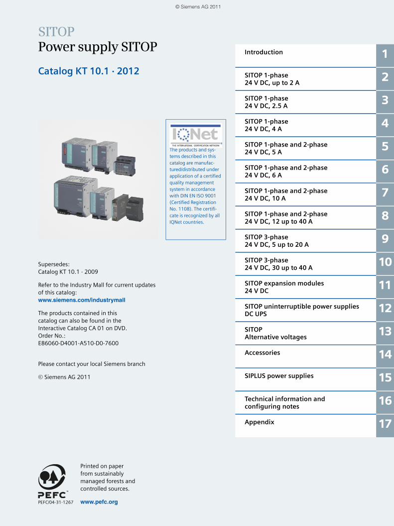
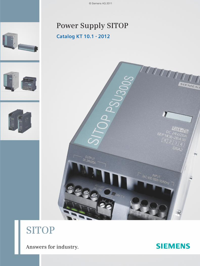
SITOPPower supply SITOP
Catalog KT 10.1 · 2012
Supersedes:Catalog KT 10.1 · 2009
Refer to the Industry Mall for current updates of this catalog:www.siemens.com/industrymall
The products contained in this catalog can also be found in the Interactive Catalog CA 01 on DVD.Order No.: E86060-D4001-A510-D0-7600
Please contact your local Siemens branch
© Siemens AG 2011
The products and sys-tems described in this catalog are manufac-tured/distributed under application of a certified quality management system in accordance with DIN EN ISO 9001 (Certified Registration No. 1108). The certifi-cate is recognized by all IQNet countries.
Introduction 1
SITOP 1-phase24 V DC, up to 2 A
2
SITOP 1-phase24 V DC, 2.5 A
3
SITOP 1-phase24 V DC, 4 A
4
SITOP 1-phase and 2-phase24 V DC, 5 A
5
SITOP 1-phase and 2-phase24 V DC, 6 A
6
SITOP 1-phase and 2-phase24 V DC, 10 A
7
SITOP 1-phase and 2-phase24 V DC, 12 up to 40 A
8
SITOP 3-phase24 V DC, 5 up to 20 A
9
SITOP 3-phase24 V DC, 30 up to 40 A
10
SITOP expansion modules24 V DC
11
SITOP uninterruptible power suppliesDC UPS
12
SITOPAlternative voltages
13
Accessories 14
SIPLUS power supplies 15
Technical information and configuring notes
16
Appendix 17
Printed on paper from sustainably managed forests and controlled sources.
www.pefc.orgPEFC/04-31-1267
KT10_EN_gesamt.book Seite 1 Mittwoch, 12. Oktober 2011 11:00 11
© Siemens AG 2011

1/2 Siemens KT 10.1 · 2012
KT10_EN_gesamt.book Seite 2 Mittwoch, 12. Oktober 2011 11:00 11
© Siemens AG 2011
1/3Siemens KT 10.1 · 2012
Answers for industry.
Siemens Industry answers the challenges in the
manufacturing and the process industry as well as in
the building automation business. Our drive and automation
solutions based on Totally Integrated Automation (TIA) and
Totally Integrated Power (TIP) are employed in all kinds
of industry. In the manufacturing and the process industry.
In industrial as well as in functional buildings.
Siemens offers automation, drive, and low-voltage switching technology as well as industrial software from stan-dard products up to entire industry solu-tions. The industry software enables our industry customers to optimize the en-tire value chain – from product design and development through manufacture and sales up to after-sales service. Our electrical and mechanical components offer integrated technologies for the en-tire drive train – from couplings to gear units, from motors to control and drive solutions for all engineering industries. Our technology platform TIP offers ro-bust solutions for power distribution.
The high quality of our products sets industry-wide benchmarks. High environmental aims are part of our eco-management, and we imple-ment these aims consistently. Right from product design, possible effects on the environment are examined. Hence many of our products and systems are RoHS compliant (Restriction of Hazard-ous Substances). As a matter of course, our production sites are certified ac-cording to DIN EN ISO 14001, but to us, environmental protection also means most efficient utilization of valuable resources. The best example are our energy-efficient drives with energy sav-ings up to 60 %.
Check out the opportunities our automation and drive solutions provide. And discover how you can sustainably enhance your competitive edge with us.
KT10_EN_gesamt.book Seite 3 Mittwoch, 12. Oktober 2011 11:00 11
© Siemens AG 2011

1/4 Siemens KT 10.1 · 2012
SIMATIC IT
IO-Link
PROFIBUS PA
HART
TotallyIntegratedAutomation
SIMATIC Distributed I/O
SIMATIC ControllersModular / PC-based
• Energy Management• Asset Management
Field Level
SIMATIC IdentIndustrial Identification
Process Instrumentation
SIMATIC NETIndustrialCommunication
SIMOTIONMotion Control
SINUMERIKComputer Numerical Control
Industrial Software for• Product Design• Production Planning• Engineering
• Commissioning• Operation• Maintenance• Modernization and Upgrade
ERP – Enterprise Resource Planning
MES – Manufacturing Execution Systems
SIMATIC PCS 7Process Control (DCS)
Operations Level
Management Level
Control Level
Setting standards in productivity and competitiveness.
Totally Integrated Automation.
KT10_EN_gesamt.book Seite 4 Mittwoch, 12. Oktober 2011 11:00 11
© Siemens AG 2011
1/5Siemens KT 10.1 · 2012
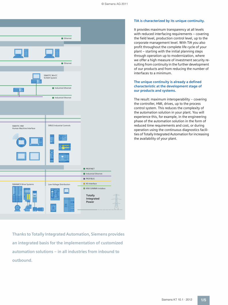
KNX GAMMA instabus
AS-Interface
PROFIBUS
Industrial Ethernet
PROFINET
TotallyIntegrated Power
Industrial Ethernet
Industrial Ethernet
Ethernet
Ethernet
SINAMICS Drive Systems Low-Voltage Distribution
SIMATIC HMIHuman Machine Interface
SIRIUS Industrial Controls
SIMATIC WinCCSCADA-System
Thanks to Totally Integrated Automation, Siemens provides
an integrated basis for the implementation of customized
automation solutions – in all industries from inbound to
outbound.
TIA is characterized by its unique continuity.
It provides maximum transparency at all levels with reduced interfacing requirements – covering the field level, production control level, up to the corporate management level. With TIA you also profit throughout the complete life cycle of your plant – starting with the initial planning steps through operation up to modernization, where we offer a high measure of investment security re-sulting from continuity in the further development of our products and from reducing the number of interfaces to a minimum.
The unique continuity is already a defined characteristic at the development stage of our products and systems.
The result: maximum interoperability – covering the controller, HMI, drives, up to the process control system. This reduces the complexity of the automation solution in your plant. You will experience this, for example, in the engineering phase of the automation solution in the form of reduced time requirements and cost, or during operation using the continuous diagnostics facili-ties of Totally Integrated Automation for increasing the availability of your plant.
KT10_EN_gesamt.book Seite 5 Mittwoch, 12. Oktober 2011 11:00 11
© Siemens AG 2011

SelectingFind your products in the structure tree, in the new "Bread-crumb" navigation or with the integral search machine with expert functions. Electronic configurators are also integrated into the Mall. Enter the various characteristic values and the appropriate product will be dis-played with the relevant order numbers. You can save configurations, load them and reset them to their initial status.
OrderingYou can load the products that you have selected in this way into the shopping basket at a click of the mouse. You can create your own tem-plates and you will be informed about the availability of the products in your shopping cart. You can load the completed parts lists directly into Excel or Word.
Delivery statusWhen you have sent the order, you will receive a short e-mail confir-mation which you can print out or save. With a click on "Carrier", you will be directly connected to the website of the carrier where you can easily track the delivery status.
Added value due to additional informationSo you have found your product and want more information about it? In just a few clicks of the mouse, you will arrive at the image data base, manuals and operating instructions. Create your own user documen-tation with My Documentation Manager.Also available are FAQs, software downloads, certificates and techni-cal data sheets as well as our training programs. In the image database you will find, depending on the product, 2D/3D graphics, dimension drawings and exploded drawings, characteristic curves or circuit diagrams which you can download.
Convinced? We look forward to your visit!
Much more than a catalog.The Industry Mall.
You have a catalog in your hands that will serve you well for selecting and ordering your products. But have you heard of the electronic online cata-log (the Industry Mall) and all its benefits? Take a look around it sometime:
www.siemens.com/industrymall
KT10_EN_gesamt.book Seite 14 Mittwoch, 12. Oktober 2011 11:00 11
© Siemens AG 2011
1/7Siemens KT 10.1 · 2012
SITOP power supplies
Energy efficient and usable world-wide
The fan-free power supplies deliver sta-bilized 24 Volts and are characterized by their compact and rugged design, high overload capability, as well as special energy efficiency. The high efficiency across the entire load range and the low no-load loss ensure efficient operation. The large input voltage range and the international approvals mean that use is possible in almost all supply networks worldwide.
Every day, SITOP is used successfully in innumerable practical applications.
Quick selection and fast delivery
With the SITOP Selection Tool - available in the Internet under www.siemens.com/sitop-selection-tool and in the Industry Mall - the suitable power supply can be selected quickly and easily The selected products can be saved or placed into the Mall's shopping cart and then ordered there.
We deliver all SITOP standard products from stock to ensure that you receive the SITOP power supply you selected quickly.
Customized SITOP products
Our standard power supplies cannot, of course, satisfy the requirements of ev-ery application. We can design a specific power supply for your application-spe-cific requirements. You benefit from the expertise of large-scale production and gain maximum development security and quality.
Our customer-specific solutions are used today in many sectors of mechani-cal engineering, in automation technol-ogy, vehicle electronics, equipment manufacturing, or in industrial instru-mentation technology.
If your are interested, please contact your local Siemens office.
The benchmark in reliability, compactness and functionality
Efficient operation of a machine or plant requires a reliable, con-stant power supply. The quality and reliability of the SITOP stabi-lized power supplies ensure high levels of safety in DC power sup-ply in industrial engineering and building management systems.
Our extensive selection of SITOP power supplies is enhanced by expansion modules that extensively protect the 24 V power sup-plies against interference on the primary and secondary side, right up to complete all-round protection.
KT10_EN_gesamt.book Seite 7 Mittwoch, 12. Oktober 2011 11:00 11
© Siemens AG 2011
1/8 Siemens KT 10.1 · 2012
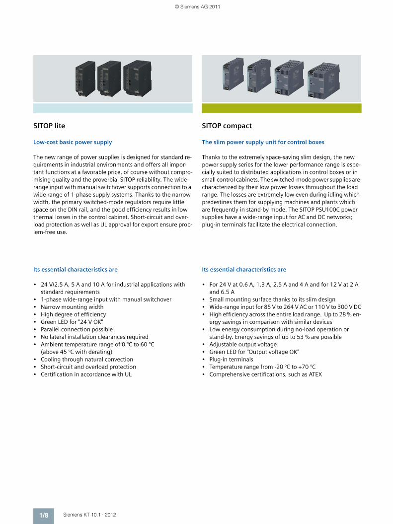
SITOP lite
Low-cost basic power supply
The new range of power supplies is designed for standard re-quirements in industrial environments and offers all impor-tant functions at a favorable price, of course without compro-mising quality and the proverbial SITOP reliability. The wide-range input with manual switchover supports connection to a wide range of 1-phase supply systems. Thanks to the narrow width, the primary switched-mode regulators require little space on the DIN rail, and the good efficiency results in low thermal losses in the control cabinet. Short-circuit and over-load protection as well as UL approval for export ensure prob-lem-free use.
Its essential characteristics are
• 24 V/2.5 A, 5 A and 10 A for industrial applications with standard requirements
• 1-phase wide-range input with manual switchover• Narrow mounting width • High degree of efficiency• Green LED for "24 V OK"• Parallel connection possible• No lateral installation clearances required• Ambient temperature range of 0 °C to 60 °C
(above 45 °C with derating)• Cooling through natural convection• Short-circuit and overload protection• Certification in accordance with UL
SITOP compact
The slim power supply unit for control boxes
Thanks to the extremely space-saving slim design, the new power supply series for the lower performance range is espe-cially suited to distributed applications in control boxes or in small control cabinets. The switched-mode power supplies are characterized by their low power losses throughout the load range. The losses are extremely low even during idling which predestines them for supplying machines and plants which are frequently in stand-by mode. The SITOP PSU100C power supplies have a wide-range input for AC and DC networks; plug-in terminals facilitate the electrical connection.
Its essential characteristics are
• For 24 V at 0.6 A, 1.3 A, 2.5 A and 4 A and for 12 V at 2 A and 6.5 A
• Small mounting surface thanks to its slim design• Wide-range input for 85 V to 264 V AC or 110 V to 300 V DC• High efficiency across the entire load range. Up to 28 % en-
ergy savings in comparison with similar devices• Low energy consumption during no-load operation or
stand-by. Energy savings of up to 53 % are possible• Adjustable output voltage• Green LED for "Output voltage OK"• Plug-in terminals• Temperature range from -20 °C to +70 °C• Comprehensive certifications, such as ATEX
KT10_EN_gesamt.book Seite 8 Mittwoch, 12. Oktober 2011 11:00 11
© Siemens AG 2011
1/9Siemens KT 10.1 · 2012
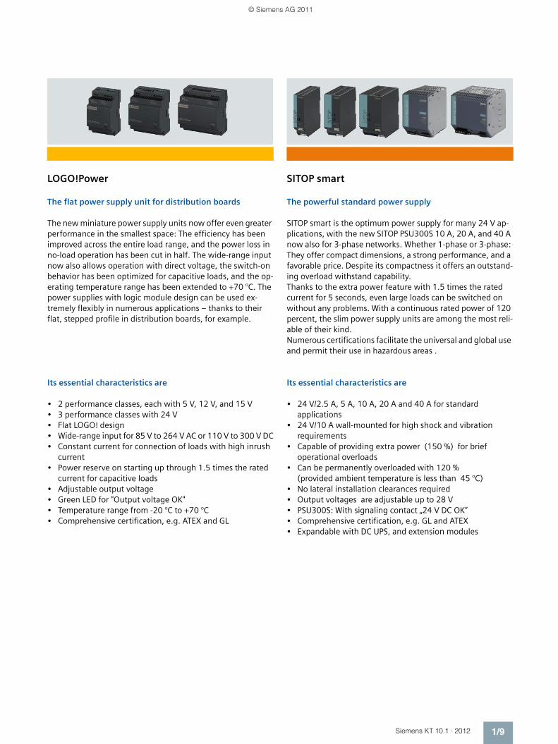
LOGO!Power
The flat power supply unit for distribution boards
The new miniature power supply units now offer even greater performance in the smallest space: The efficiency has been improved across the entire load range, and the power loss in no-load operation has been cut in half. The wide-range input now also allows operation with direct voltage, the switch-on behavior has been optimized for capacitive loads, and the op-erating temperature range has been extended to +70 °C. The power supplies with logic module design can be used ex-tremely flexibly in numerous applications – thanks to their flat, stepped profile in distribution boards, for example.
Its essential characteristics are
• 2 performance classes, each with 5 V, 12 V, and 15 V• 3 performance classes with 24 V• Flat LOGO! design• Wide-range input for 85 V to 264 V AC or 110 V to 300 V DC• Constant current for connection of loads with high inrush
current• Power reserve on starting up through 1.5 times the rated
current for capacitive loads• Adjustable output voltage• Green LED for "Output voltage OK"• Temperature range from -20 °C to +70 °C• Comprehensive certification, e.g. ATEX and GL
SITOP smart
The powerful standard power supply
SITOP smart is the optimum power supply for many 24 V ap-plications, with the new SITOP PSU300S 10 A, 20 A, and 40 A now also for 3-phase networks. Whether 1-phase or 3-phase: They offer compact dimensions, a strong performance, and a favorable price. Despite its compactness it offers an outstand-ing overload withstand capability. Thanks to the extra power feature with 1.5 times the rated current for 5 seconds, even large loads can be switched on without any problems. With a continuous rated power of 120 percent, the slim power supply units are among the most reli-able of their kind. Numerous certifications facilitate the universal and global use and permit their use in hazardous areas .
Its essential characteristics are
• 24 V/2.5 A, 5 A, 10 A, 20 A and 40 A for standard applications
• 24 V/10 A wall-mounted for high shock and vibration requirements
• Capable of providing extra power (150 %) for brief operational overloads
• Can be permanently overloaded with 120 % (provided ambient temperature is less than 45 °C)
• No lateral installation clearances required• Output voltages are adjustable up to 28 V• PSU300S: With signaling contact „24 V DC OK“• Comprehensive certification, e.g. GL and ATEX• Expandable with DC UPS, and extension modules
KT10_EN_gesamt.book Seite 9 Mittwoch, 12. Oktober 2011 11:00 11
© Siemens AG 2011
1/10 Siemens KT 10.1 · 2012
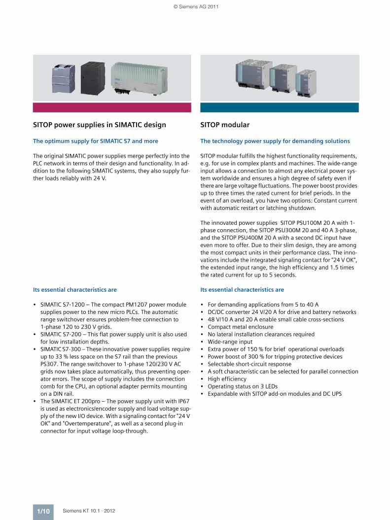
SITOP power supplies in SIMATIC design
The optimum supply for SIMATIC S7 and more
The original SIMATIC power supplies merge perfectly into the PLC network in terms of their design and functionality. In ad-dition to the following SIMATIC systems, they also supply fur-ther loads reliably with 24 V.
Its essential characteristics are
• SIMATIC S7-1200 – The compact PM1207 power module supplies power to the new micro PLCs. The automatic range switchover ensures problem-free connection to 1-phase 120 to 230 V grids.
• SIMATIC S7-200 – This flat power supply unit is also used for low installation depths.
• SIMATIC S7-300 – These innovative power supplies require up to 33 % less space on the S7 rail than the previous PS307. The range switchover to 1-phase 120/230 V AC grids now takes place automatically, thus preventing oper-ator errors. The scope of supply includes the connection comb for the CPU, an optional adapter permits mounting on a DIN rail.
• The SIMATIC ET 200pro – The power supply unit with IP67 is used as electronics/encoder supply and load voltage sup-ply of the new I/O device. With a signaling contact for "24 V OK" and "Overtemperature", as well as a second plug-in connector for input voltage loop-through.
SITOP modular
The technology power supply for demanding solutions
SITOP modular fulfills the highest functionality requirements, e.g. for use in complex plants and machines. The wide-range input allows a connection to almost any electrical power sys-tem worldwide and ensures a high degree of safety even if there are large voltage fluctuations. The power boost provides up to three times the rated current for brief periods. In the event of an overload, you have two options: Constant current with automatic restart or latching shutdown.
The innovated power supplies SITOP PSU100M 20 A with 1-phase connection, the SITOP PSU300M 20 and 40 A 3-phase, and the SITOP PSU400M 20 A with a second DC input have even more to offer. Due to their slim design, they are among the most compact units in their performance class. The inno-vations include the integrated signaling contact for "24 V OK", the extended input range, the high efficiency and 1.5 times the rated current for up to 5 seconds.
Its essential characteristics are
• For demanding applications from 5 to 40 A• DC/DC converter 24 V/20 A for drive and battery networks• 48 V/10 A and 20 A enable small cable cross-sections• Compact metal enclosure• No lateral installation clearances required• Wide-range input• Extra power of 150 % for brief operational overloads• Power boost of 300 % for tripping protective devices• Selectable short-circuit response• A soft characteristic can be selected for parallel connection• High efficiency• Operating status on 3 LEDs• Expandable with SITOP add-on modules and DC UPS
KT10_EN_gesamt.book Seite 10 Mittwoch, 12. Oktober 2011 11:00 11
© Siemens AG 2011
1/11Siemens KT 10.1 · 2012
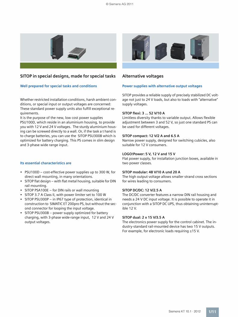
SITOP in special designs, made for special tasks
Well prepared for special tasks and conditions
Whether restricted installation conditions, harsh ambient con-ditions, or special input or output voltages are concerned: These standard power supply units also fulfill exceptional re-quirements.It is the purpose of the new, low cost power supplies PSU100D, which reside in an aluminium housing, to provide you with 12 V and 24 V voltages. The sturdy aluminium hous-ing can be screwed directly to a wall. Or, if the task a t hand is to charge batteries, you can use the SITOP PSU300B which is optimized for battery charging. This PS comes in slim design and 3-phase wide range input.
Its essential characteristics are
• PSU100D – cost-effective power supplies up to 300 W, for direct wall mounting, in many orientations.
• SITOP flat design – with flat metal housing, suitable for DIN rail mounting.
• SITOP PSA100E – for DIN rails or wall mounting• SITOP 3.7 A Class II, with power limiter set to 100 W• SITOP PSU300P – in IP67 type of protection, identical in
construction to SIMATIC ET 200pro PS, but without the sec-ond connector for looping the input voltage.
• SITOP PSU300B – power supply optimized for battery charging, with 3-phase wide-range input, 12 V and 24 V output voltages.
Alternative voltages
Power supplies with alternative output voltages
SITOP provides a reliable supply of precisely stabilized DC volt-age not just to 24 V loads, but also to loads with "alternative" supply voltages.
SITOP flexi: 3 … 52 V/10 A Limitless diversity thanks to variable output. Allows flexible adjustment between 3 and 52 V, so just one standard PS can be used for different voltages.
SITOP compact: 12 V/2 A and 6.5 ANarrow power supply, designed for switching cubicles, also suitable for 12 V consumers.
LOGO!Power: 5 V, 12 V and 15 V Flat power supply, for installation junction boxes, available in two power classes.
SITOP modular: 48 V/10 A und 20 A The high output voltage allows smaller strand cross sections for wires leading to consumers.
SITOP DC/DC: 12 V/2.5 A The DC/DC converter features a narrow DIN rail housing and needs a 24 V DC input voltage. It is possible to operate it in conjunction with a SITOP DC UPS, thus obtaining uninterrupt-ible 12 V.
SITOP dual: 2 x 15 V/3.5 A The electronics power supply for the control cabinet. The in-dustry-standard rail-mounted device has two 15 V outputs. For example, for electronic loads requiring ±15 V.
KT10_EN_gesamt.book Seite 11 Mittwoch, 12. Oktober 2011 11:00 11
© Siemens AG 2011

1/12 Siemens KT 10.1 · 2012
Expansion modules
Reliable protection against the most varied hazard sources: SITOP expansion modules
A power supply unit on its own cannot guarantee fault-free 24 V supply. Power failures, extreme variations in the mains voltage, or a faulty load can bring plant operation to a stand-still and cause high costs. The expansion modules offer every-thing from extensive protection against interference on the primary and secondary side right up to complete all-round protection.
• The signaling module with signal contacts and remote ON/OFF function optimally integrates SITOP modular (devices without integral signaling contact) into automated plants.
• For maximum availability, the redundancy module decou-ples SITOP power supplies of the same type.
• The buffer module bridges short power failures up to 3 sec-onds with capacitors as energy storage.
• The SITOP select diagnostics module and the new SITOP PSE200U selectivity module offer selective protection of in-dividual 24 V paths against overload and short-circuits. With this protection and by means of fast fault localization, downtimes can be reduced to a minimum. New features of the selectivity module include the finely adjustable current range (from 0.5 A), remote reset, and a reset button for each channel.
DC UPS
Permanently reliable 24 V – even when the power fails: Uninterruptible power supplies
Supply network irregularities in the millisecond range are compensated for supremely well by all our power supplies. Large fluctuations or even power failures, however, require special measures: The buffer module (see SITOP expansion modules) ensures optimal protection in the case of brief power failures up to 3 seconds.
SITOP UPS500 uses capacitors to cover power failures in the time range of minutes. Its essential characteristics are:
• Absolutely maintenance free DC UPS featuring high-capac-ity double-layer capacitors.
• Modularly cascadable for standard mounting rail: Basic unit SITOP UPS500S 24 V / 15 A with integrated energy stor-age 2.5 oder 5 kWs, combinable with up to three expansion modules UPS501S (5 kWs).
• SITOP UPS500P 24 V / 7 A, 5 or 10 kWs in IP65 type of pro-tection, for distributed use.
• Long-life capacitors protect your investment, replacements can be postponed: After 8 years the UPS500 (at 50 °C ambient temperature) still retains 80 % of its rated capacity.
• No ventilation is required in the installation area (VDE 0510 Part 2 / EN 50272-2).
• Fast restoration of buffering capability.
DC UPS modules outfitted with batteries secure operation in the time range of hours. Its essential characteristics are:
• DC UPS modules 6 A, 15 A and 40 A.• Maintenance-free battery modules from 1.2 to 12 Ah.• High security and availability due to monitoring of back-up
capability status, battery cables, aging and charging status.• Long service life of consumers, and batteries , facilitated by
an integrated battery management.• DIP switches can be used for setting the following: Connec-
tion threshold for buffering, end-of-charge voltage, charg-ing current, buffering time.
• Uninterrupted transition from „buffer ready“ to „buffering“.
Both DC UPS systems can be incorporated into PC-based auto-mation solutions with a free software tool. This tool supports the processing of status annunciations and the secure shut-ting down of the PC.
KT10_EN_gesamt.book Seite 12 Mittwoch, 12. Oktober 2011 11:00 11
© Siemens AG 2011
1/13Siemens KT 10.1 · 2012
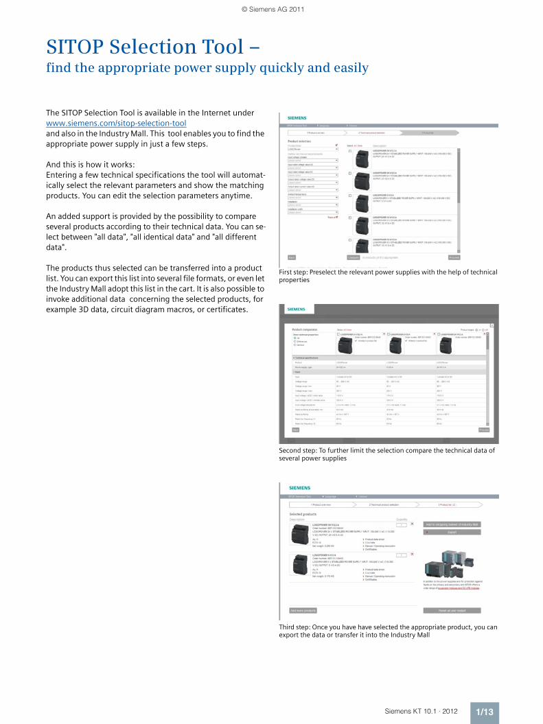
SITOP Selection Tool – find the appropriate power supply quickly and easily
The SITOP Selection Tool is available in the Internet under www.siemens.com/sitop-selection-tool and also in the Industry Mall. This tool enables you to find the appropriate power supply in just a few steps.
And this is how it works: Entering a few technical specifications the tool will automat-ically select the relevant parameters and show the matching products. You can edit the selection parameters anytime.
An added support is provided by the possibility to compare several products according to their technical data. You can se-lect between "all data", "all identical data" and "all different data".
The products thus selected can be transferred into a product list. You can export this list into several file formats, or even let the Industry Mall adopt this list in the cart. It is also possible to invoke additional data concerning the selected products, for example 3D data, circuit diagram macros, or certificates.
First step: Preselect the relevant power supplies with the help of technical properties
Second step: To further limit the selection compare the technical data of several power supplies
Third step: Once you have have selected the appropriate product, you can export the data or transfer it into the Industry Mall
KT10_EN_gesamt.book Seite 13 Mittwoch, 12. Oktober 2011 11:00 11
© Siemens AG 2011

1/14 Siemens KT 10.1 · 2012
Input voltage Output current SITOPlite
SITOPcompact
LOGO!Power SITOPsmart
SIMATIC design SITOPmodular
Special designspecial uses
Output voltage 24 V DC The complete technical specifications on these products are on the pages shown
1-phase AC
120 V, 230 V 0.6 A 2/2
1.3 A 2/2 2/3
2 A 2/3
2.1 A 3/3
2.5 A 3/3 3/2 3/2 3/2 3/3 3/3
3.1 A 4/3
3.5 A 4/2
3.7 A 4/3
4 A 4/2 4/2 4/3
4.1 A 4/3
5 A 5/3 5/2 5/3 5/2 5/3
6 A 6/2
6.2 A 6/2
10 A 7/3 7/2 7/3 7/2 7/3
12 A 8/2
12.5 A 8/2
20 A 8/2, 8/3
40 A 8/3
1-phase DC
48 ... 220 V 0.375 A 2/2
48 ... 110 V 2 A 2/3
24 ... 110 V 2 A 2/3
110 ... 300 V 0.6 A 2/2
1.3 A 2/2 2/3
2.5 A 3/2 3/2
4 A 4/2 4/2
120 ... 375 V 2.1 A
3.1 A
4.1 A
6.2 A
12 A
200 ... 900 V 20 A 8/3
3-phase AC
400 ... 500 V 5 A 5/2, 9/2
8 A 9/2
10 A 9/3 7/2, 9/2
20 A 9/3 8/2, 8/3, 9/3
30 A 10/2
40 A 10/3 8/3, 10/2, 10/3
Selection tableSITOP power supplies
KT10_EN_gesamt.book Seite 14 Mittwoch, 12. Oktober 2011 11:00 11
© Siemens AG 2011

1/15Siemens KT 10.1 · 2012
Input voltage Output current SITOPlite
SITOPcompact
LOGO!Power SITOPsmart
SIMATIC design SITOPmodular
Special designspecial uses
Output voltage
5, 12, 15, 48 V DC
The complete technical specifications on these products are on the pages shown
1-phase AC
120 V, 230 V 3 - 52 V/2 - 10 A
13/2
5 V/3 A 13/4
5 V/6.3 A 13/4
12 V/1.9 A 13/6
12 V/2 A 13/6
12 V/3 A 13/7
12 V/4.5 A 13/7
12 V/6.5 A 13/7
12 V/8.3 A 13/10
15 V/1.9 A 13/12
15 V/4 A 13/12
2 x 15 V/3.5 A 13/12
1-phase DC
24 V 12 V/2.5 A 13/6
110 ... 300 V 5 V/3 A 13/4
5 V/6.3 A 13/4
12 V/1.9 A 13/6
12 V/2 A 13/6
12 V/4.5 A 13/7
12 V/6.5 A 13/7
15 V/1.9 A 13/12
15 V/4 A 13/12
3-phase AC
400 ... 500 V 12 V/20 A 13/10
48 V/10 A 13/14
48 V/20 A 13/14
KT10_EN_gesamt.book Seite 15 Mittwoch, 12. Oktober 2011 11:00 11
© Siemens AG 2011

1/16 Siemens KT 10.1 · 2012
KT10_EN_gesamt.book Seite 16 Mittwoch, 12. Oktober 2011 11:00 11
© Siemens AG 2011

Siemens KT 10.1 · 2012
22/2 The smallest ones 0.375 A2/2 SITOP PSU100C 0.6 A2/2 SITOP PSU100C 1.3 A2/3 LOGO!Power 1.3 A2/3 The S7-300 version 2 A2/3 The outdoor version 2 A2/3 The DC/DC converter 2 A2/6 Ordering data and additional information
SITOP 1-phase24 V DC, up to 2 A
Export regulations AL and ECCNsee page 17/9
KT10_EN_gesamt.book Seite 1 Mittwoch, 12. Oktober 2011 11:00 11
© Siemens AG 2011

SITOP 1-phase24 V DC
Output current up to 2 A
2/2 Siemens KT 10.1 · 2012
2
■ Overview
■ Technical data
1) SIPLUS module see page 15/2.
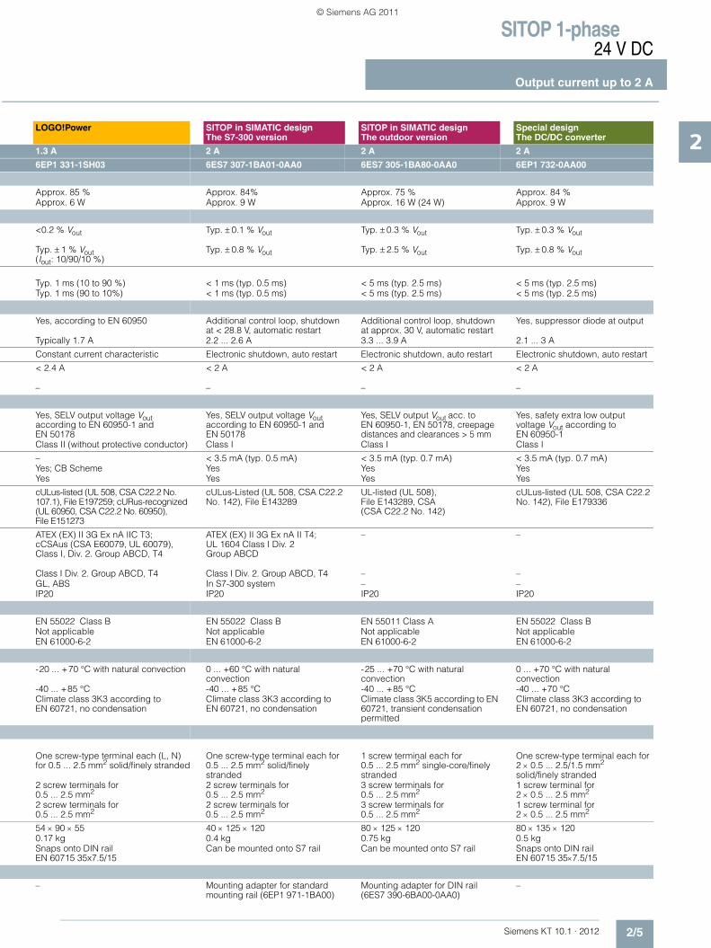
Product Special designThe smallest ones
SITOP compact PSU100C
SITOP compact PSU100C
Power supply, type 0.375 A 0.6 A 1.3 A
Order No. 6EP1 731-2BA00 1) 6EP1 331-5BA00 6EP1 331-5BA10
The product families are highlighted in the same color.For an explanation of the product families, see chapter 1, pages 1/8 through 1/12.
The optimum power supply units for automation solutions in the lowest performance range; with wide-range input for AC or DC voltages; thanks to their compact and slim design, they are particularly suitable for solutions where space is limited and in conjunction with low-voltage switchgear.
Narrow power supply in the lower performance range, e.g. for distributed use in cubicles. Low energy consumption over the entire power range, minimal energy loss at no load, with removable terminals.
Narrow power supply in the lower performance range, e.g. for distributed use in cubicles. Low energy consumption over the entire power range, minimal energy loss at no load, with removable terminals.
Product Special design The smallest ones
SITOP compactPSU100C
SITOP compactPSU100C
Input
DC voltage 1-phase AC or DC 1-phase AC or DCRated voltage value Vin rated 48-220 V DC
Wide-range input100-230 V AC Wide-range input
100-230 V AC Wide-range input
Voltage range 30 ... 264 V (AC 30 ... 187 V AC)
85 ... 264 V AC or 110 ... 300 V DC 85 ... 264 V AC or 110 ... 300 V DC
Overvoltage resistance 2.3 x Vin rated, 1.3 ms 2.3 x Vin rated, 1.3 ms
Mains buffering at Iout rated
> 10 ms at Vin = 220 V > 20 ms at Vin = 230 V > 20 ms at Vin = 230 V
Rated line frequency value; range – 50/60 Hz; 47 ... 63 Hz 50/60 Hz; 47 ... 63 Hz
Rated current Iin rated 0.3-0.06 A 0.28-0.18 A 0.63-0.31 ASwitch-on current limit (+25 °C) < 35 A, typ. 3 ms < 28 A < 34 AI2t 1.2 A2s 0.7 A2s 1.2 A2s
Built-in incoming fuse F 4 A/250 V (not accessible) Internal InternalRecommended miniature circuit breaker (IEC 898) in the mains power input
6 A or higher, characteristic C, suitable for DC
16 A or higher, characteristic B or 10 A or higher, characteristic C
16 A or higher, characteristic B or 10 A or higher, characteristic C
Output
Controlled, isolated DC voltage Controlled, isolated DC voltage Controlled, isolated DC voltageRated voltage Vout rated 24 V DC 24 V DC 24 V DC
Total tolerance ± 3 % ± 3 % ± 3 %• Static line compensation Approx. 0.1 % Approx. 0.1 %• Static load compensation Approx. 0.1 % Approx. 0.2%
Residual ripple < 150 mVpp (typ. 50 mVpp) < 200 mVpp (typ. 40 mVpp) < 200 mVpp (typ. 25 mVpp)Spikes (bandwidth: 20 MHz) < 240 mVpp (typ. 50 mVpp) < 300 mVpp (typ. 20 mVpp) < 300 mVpp (typ. 20 mVpp)
Adjustment range – – 22.2 ... 26.4 VStatus display Green LED for 24 V OK Green LED for 24 V OK Green LED for 24 V OKOn/off behavior No overshoot of Vout
(soft start)Overshoot of Vout approx. 5 % Overshoot of Vout approx. 5 %
Startup delay /voltage rise
< 2.5 s/typ. 90 ms < 1 s/typ. 25 ms < 0.6 s/typ. 90 ms
Rated current value Iout rated 0.375 A 0.6 A 1.3 A
Current range • Up to + 60 °C 0 ... 0.375 A 0 ... 0.6 A (up to +55 °C) 0 ... 1.3 A (up to +55 °C)• Derating 0 ... 0.255 A (up to +70 °C) 0 ... 0.33 A (up to +70 °C) 0 ... 0.7 A (up to +70 °C)
Dynamic overcurrent on • Power-up on short circuit• Short circuit during operation Typ. 2.7 A for 200 ms Typically 1 A Typically 3.1 A
Parallel switching for enhanced performance
Not permitted Not permitted Yes, 2 units
NEW NEW
KT10_EN_gesamt.book Seite 2 Mittwoch, 12. Oktober 2011 11:00 11
© Siemens AG 2011

SITOP 1-phase24 V DC
Output current up to 2 A
2/3Siemens KT 10.1 · 2012
2
2) SIPLUS module see page 15/2.
LOGO!Power SITOP in SIMATIC designThe S7-300 version
SITOP in SIMATIC designThe outdoor version
Special designThe DC/DC converter
1.3 A 2 A 2 A 2 A
6EP1 331-1SH03 6ES7 307-1BA01-0AA0 6ES7 305-1BA80-0AA0 2) 6EP1 732-0AA00
LOGO!Power supplies are optimally matched in design and functionality to the LOGO! logic modules; with wide-range input 85 V to 264 V AC and 110 V to 300 V DC, as well as an option for installing in built-in miniature distribution boards, they can be used universally in the low-end performance range.
The proven power supply in SIMATIC S7-300 design; with PS-CPU connecting comb and for mounting directly on S7 rail.
The power supply for extreme environmental conditions in SIMATIC S7-300 design; can be snapped onto S7 rail; with PS-CPU connecting comb.
The DC/DC converter for supply from battery and DC systems; with a wide input voltage range from 38 V to 121 V DC.
LOGO!Power SITOP in SIMATIC designThe S7-300 version
SITOP in SIMATIC designThe outdoor version
Special designThe DC/DC converter
1-phase AC or DC 1-phase AC DC voltage DC voltage100-240 V AC Wide-range input
120/230 V AC Automatic range switch-over
24 V-110 V DCWide-range input
48-110 V DCWide-range input
AC 85 ... 264 V or DC 110 ... 300 V 85 ... 132 V/170 ... 264 V 16.8 ... 138 V 38 ... 121 V
2.3 × Vin rated, 1.3 ms 2.3 × Vin rated, 1.3 ms 154 V; 0.1 s
> 40 ms at Vin = 187 V > 20 ms at Vin = 93/187 V > 10 ms at Vin rated > 5 ms at Vin = 48 V
50/60 Hz; 47 ... 63 Hz 50/60 Hz, 47 ... 63 Hz – –
0.7-0.35 A 0.9/0.5 A 2.7-0.6 A (4.0-0.9 A) 1.2-0.5 A< 25 A < 22 A, < 3 ms < 20 A, < 10 ms < 33 A< 0.8 A2s < 1.0 A2s < 5 A2s
Internal T 1.6 A/250 V (not accessible) T 6.3 A/250 V (not accessible) T 2.5 A (not accessible)16 A or higher, characteristic B or 10 A or higher, characteristic C
3 A, characteristic C 10 A or higher, characteristic C, suitable for DC
10 to 25 A, characteristic B, or 6 to 25 A, characteristic C, DC-compatible
Controlled, isolated DC voltage Controlled, isolated DC voltage Controlled, isolated DC voltage Controlled, isolated DC voltage24 V DC 24 V DC 24 V DC 24 V DC
± 3 % ±3 % ± 3 % ±1 %Approx. 0.1 % Approx. 0.1 % Approx. 0.2 % Approx. 0.1 %Approx. 1.5 % Approx. 0.2 % Approx. 0.4% Approx. 0.4 %
< 200 mVpp (typ. 10 mVpp) < 50 mVpp (typ. < 5 mVpp) < 150 mVpp (typ. < 30 mVpp) < 100 mVpp< 300 mVpp (typ. 20 mVpp) < 150 mVpp (typ. < 20 mVpp) < 240 mVpp (typ. < 150 mVpp) < 300 mVpp
22.2 ... 26.4 V – – 23.5 ... 26.5 VGreen LED for 24 V OK Green LED for 24 V OK Green LED for 24 V OK Green LED for 24 V OKNo overshoot of Vout (soft start)
No overshoot of Vout (soft start)
No overshoot of Vout(soft start)
Overshoot of Vout on startup max. 25 V
< 0.5 s/typ. 15 ms < 2 s/typ. 10 ms < 3 s/typ. 5 ms < 3 s/typ. 30 ms
1.3 A 2 A 2 A (3 A at Vin > 24 V) 2 A
0 ... 1.3 A (up to +55 °C) 0 ... 2 A 0 ... 2 A (3 A) 0 ... 2 A 0 ... 0.9 A (up to +70 °C) – – 0 ... 2 A (up to +70 °C)
Typ. 9 A for 90 ms Typ. 9 A for 270 msTyp. 9 A for 90 ms Typ. 9 A for 270 ms
Yes, 2 units Yes Yes, 2 units Yes, 2 units
NEW
KT10_EN_gesamt.book Seite 3 Mittwoch, 12. Oktober 2011 11:00 11
© Siemens AG 2011

SITOP 1-phase24 V DC
Output current up to 2 A
2/4 Siemens KT 10.1 · 2012
2
■ Technical specifications (continued)
Product Special design The smallest ones
SITOP compactPSU100C
SITOP compactPSU100C
Power supply, type 0.375 A 0.6 A 1.3 A
Order No. 6EP1 731-2BA00 6EP1 331-5BA00 6EP1 331-5BA10
Efficiency
Efficiency at Vout rated, Iout rated Approx. 66% Approx. 82 % Approx. 86 % Power loss at Vout rated, Iout rated Approx. 4.6 W Approx. 2.6 W Approx. 4.5 W
Closed-loop control
Dyn. mains compensation (Vin rated ± 15 %)
Typ. ± 0.3 % Vout Typ. ±0.1 % Vout Typ. ±0.1 % Vout
Dynamic load smoothing(Iout: 50/100/50 %)
Typ. ± 0.4 % Vout Typ. ±3 % Vout(Iout: 10/90/10 %)
Typ. ±3 % Vout(Iout: 10/90/10 %)
Load step settling time• 50 to 100 % Typ. 2 ms Typ. 3 ms (10 to 90 %) Typ. 5 ms (10 to 90 %)• 100 to 50 % Typ. 2 ms Typ. 3 ms (10 to 90 %) Typ. 5 ms (10 to 90 %)
Protection and monitoring
Output overvoltage protection Yes, according to EN 60950 Yes, according to EN 60950 Yes, according to EN 60950
Current limitation 0.41 ... 0.49 A Typically 0.7 A Typically 1.4 A
Short-circuit protection Electronic shutdown, auto restart Electronic shutdown, auto restart Electronic shutdown, auto restart
Sustained short-circuit current rms value
< 0.9 A
Overload/short-circuit indicator – – –
Safety
Primary/secondary isolation Yes, SELV output voltage Vout according to EN 60950-1 and EN 50178
Yes, SELV output voltage Vout according to EN 60950-1 and EN 50178
Yes, SELV output voltage Vout according to EN 60950-1 and EN 50178
Protection class Class I Class I Class I
Leakage current < 3.5 mA < 3.5 mA < 3.5 mASafety test Yes Yes; CB Scheme Yes; CB SchemeCE mark Yes Yes Yes
UL/cUL (CSA) approval cULus-listed (UL 508, CSA C22.2 No. 142), File E143289; cURus-recognized (UL 60950, CSA C22.2 No. 60950), File E151273
cULus-Listed (UL 508, CSA C22.2 No. 107.1), File E197259; cCSAus (CSA C22.2 No. 60950-1, UL 60950-1)
cULus-Listed (UL 508, CSA C22.2 No. 107.1), File E197259; cCSAus (CSA C22.2 No. 60950-1, UL 60950-1)
Explosion protection – ATEX (EX) II 3G Ex nA IIC T4;cCSAus (CSA C22.2 No. 213-M1987, ANSI/ISA-12.12.01-2007) Class I, Div. 2. Group ABCD, T4
ATEX (EX) II 3G Ex nA IIC T4;cCSAus (CSA C22.2 No. 213-M1987, ANSI/ISA-12.12.01-2007) Class I, Div. 2. Group ABCD, T4
FM approval – – –Marine approval – GL and ABS available soon GL and ABS available soonDegree of protection (EN 60529) IP20 IP20 IP20
EMC
Emitted interference EN 55022 Class B EN 55022 Class B EN 55022 Class BSupply harmonics limitation Not applicable Not applicable Not applicableNoise immunity EN 61000-6-2 EN 61000-6-2 EN 61000-6-2
Operating data
Ambient temperature range -25 ... +70 °C with natural convection
-20 ... +70 °C with natural convection
-20 ... +70 °C with natural convection
Transport/storage temp. range -40 ... +70 °C -40 ... +85 °C -40 ... +85 °CHumidity class Climate class 3K3 according to
EN 60721, no condensationClimate class 3K3 according to EN 60721, no condensation
Climate class 3K3 according to EN 60721, no condensation
Mechanics
Connections • Supply input L, N, PE
(DC input: L+1, M1, PE)1 screw terminal each for 0.5 ... 2.5 mm2 single-core/finely stranded
Removable screw terminals, one each 0.5 ... 2.5 mm2 solid/finely stranded
Removable screw terminals, one each 0.5 ... 2.5 mm2 solid/finely stranded
• Output + 1 screw terminal for 0.5 ... 2.5 mm2
1 screw terminal for 0.5 ... 2.5 mm2
1 screw terminal for 0.5 ... 2.5 mm2
• Output – 2 screw terminals for 0.5 ... 2.5 mm2
2 screw terminals for 0.5 ... 2.5 mm2
2 screw terminals for 0.5 ... 2.5 mm2
Dimensions (W x H x D) in mm 22.5 × 80 × 91 22.5 x 80 x 100 30 x 80 x 100 Weight, approx. 0.14 kg 0.12 kg 0.17 kgInstallation Snaps onto DIN rail
EN 60715 35x7.5/15Snaps onto DIN rail EN 60715 35x7.5/15
Snaps onto DIN rail EN 60715 35x7.5/15
Accessories
– Removable spring-loaded terminals (6EP1971-5BA00)
Removable spring-loaded terminals (6EP1971-5BA00)
KT10_EN_gesamt.book Seite 4 Mittwoch, 12. Oktober 2011 11:00 11
© Siemens AG 2011
SITOP 1-phase24 V DC
Output current up to 2 A
2/5Siemens KT 10.1 · 2012
2LOGO!Power SITOP in SIMATIC design
The S7-300 versionSITOP in SIMATIC designThe outdoor version
Special designThe DC/DC converter
1.3 A 2 A 2 A 2 A
6EP1 331-1SH03 6ES7 307-1BA01-0AA0 6ES7 305-1BA80-0AA0 6EP1 732-0AA00
Approx. 85 % Approx. 84% Approx. 75 % Approx. 84 %Approx. 6 W Approx. 9 W Approx. 16 W (24 W) Approx. 9 W
<0.2 % Vout Typ. ± 0.1 % Vout Typ. ± 0.3 % Vout Typ. ± 0.3 % Vout
Typ. ± 1 % Vout(Iout: 10/90/10 %)
Typ. ± 0.8 % Vout Typ. ± 2.5 % Vout Typ. ± 0.8 % Vout
Typ. 1 ms (10 to 90 %) < 1 ms (typ. 0.5 ms) < 5 ms (typ. 2.5 ms) < 5 ms (typ. 2.5 ms)Typ. 1 ms (90 to 10%) < 1 ms (typ. 0.5 ms) < 5 ms (typ. 2.5 ms) < 5 ms (typ. 2.5 ms)
Yes, according to EN 60950 Additional control loop, shutdown at < 28.8 V, automatic restart
Additional control loop, shutdown at approx. 30 V, automatic restart
Yes, suppressor diode at output
Typically 1.7 A 2.2 ... 2.6 A 3.3 ... 3.9 A 2.1 ... 3 A
Constant current characteristic Electronic shutdown, auto restart Electronic shutdown, auto restart Electronic shutdown, auto restart
< 2.4 A < 2 A < 2 A < 2 A
– – – –
Yes, SELV output voltage Vout according to EN 60950-1 and EN 50178
Yes, SELV output voltage Vout according to EN 60950-1 and EN 50178
Yes, SELV output Vout acc. to EN 60950-1, EN 50178, creepage distances and clearances > 5 mm
Yes, safety extra low output voltage Vout according to EN 60950-1
Class II (without protective conductor) Class I Class I Class I
– < 3.5 mA (typ. 0.5 mA) < 3.5 mA (typ. 0.7 mA) < 3.5 mA (typ. 0.7 mA)Yes; CB Scheme Yes Yes YesYes Yes Yes Yes
cULus-listed (UL 508, CSA C22.2 No. 107.1), File E197259; cURus-recognized (UL 60950, CSA C22.2 No. 60950), File E151273
cULus-Listed (UL 508, CSA C22.2 No. 142), File E143289
UL-listed (UL 508), File E143289, CSA (CSA C22.2 No. 142)
cULus-listed (UL 508, CSA C22.2 No. 142), File E179336
ATEX (EX) II 3G Ex nA IIC T3;cCSAus (CSA E60079, UL 60079), Class I, Div. 2. Group ABCD, T4
ATEX (EX) II 3G Ex nA II T4; UL 1604 Class I Div. 2 Group ABCD
– –
Class I Div. 2. Group ABCD, T4 Class I Div. 2. Group ABCD, T4 – –GL, ABS In S7-300 system – –IP20 IP20 IP20 IP20
EN 55022 Class B EN 55022 Class B EN 55011 Class A EN 55022 Class BNot applicable Not applicable Not applicable Not applicableEN 61000-6-2 EN 61000-6-2 EN 61000-6-2 EN 61000-6-2
-20 ... +70 °C with natural convection 0 ... +60 °C with natural convection
-25 ... +70 °C with natural convection
0 ... +70 °C with natural convection
-40 ... +85 °C -40 ... +85 °C -40 ... +85 °C -40 ... +70 °CClimate class 3K3 according to EN 60721, no condensation
Climate class 3K3 according to EN 60721, no condensation
Climate class 3K5 according to EN 60721, transient condensation permitted
Climate class 3K3 according to EN 60721, no condensation
One screw-type terminal each (L, N) for 0.5 ... 2.5 mm2 solid/finely stranded
One screw-type terminal each for 0.5 ... 2.5 mm2 solid/finely stranded
1 screw terminal each for 0.5 ... 2.5 mm2 single-core/finely stranded
One screw-type terminal each for 2 × 0.5 ... 2.5/1.5 mm2
solid/finely stranded2 screw terminals for 0.5 ... 2.5 mm2
2 screw terminals for 0.5 ... 2.5 mm2
3 screw terminals for 0.5 ... 2.5 mm2
1 screw terminal for 2 × 0.5 ... 2.5 mm2
2 screw terminals for 0.5 ... 2.5 mm2
2 screw terminals for 0.5 ... 2.5 mm2
3 screw terminals for 0.5 ... 2.5 mm2
1 screw terminal for 2 × 0.5 ... 2.5 mm2
54 × 90 × 55 40 × 125 × 120 80 × 125 × 120 80 × 135 × 1200.17 kg 0.4 kg 0.75 kg 0.5 kgSnaps onto DIN rail EN 60715 35x7.5/15
Can be mounted onto S7 rail Can be mounted onto S7 rail Snaps onto DIN rail EN 60715 35×7.5/15
– Mounting adapter for standard mounting rail (6EP1 971-1BA00)
Mounting adapter for DIN rail (6ES7 390-6BA00-0AA0)
–
KT10_EN_gesamt.book Seite 5 Mittwoch, 12. Oktober 2011 11:00 11
© Siemens AG 2011
SITOP 1-phase24 V DC
Output current up to 2 A
2/6 Siemens KT 10.1 · 2012
2
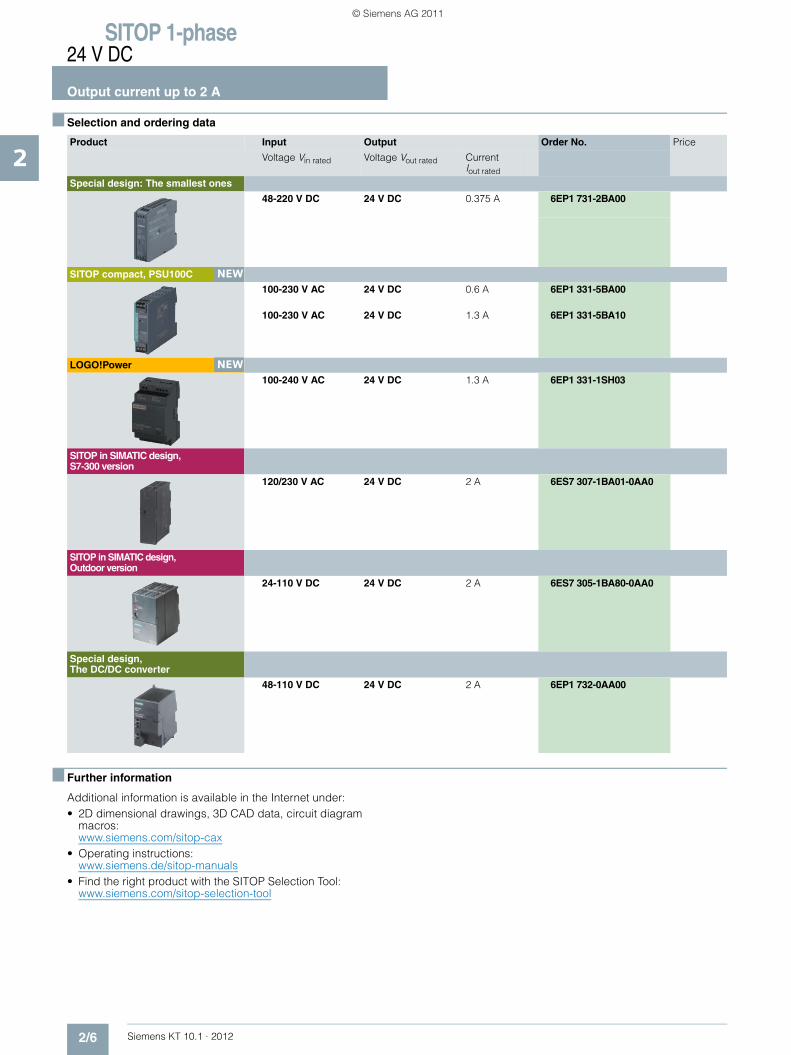
■ Selection and ordering data
■ Further information
Additional information is available in the Internet under:• 2D dimensional drawings, 3D CAD data, circuit diagram
macros: www.siemens.com/sitop-cax
• Operating instructions:www.siemens.de/sitop-manuals
• Find the right product with the SITOP Selection Tool: www.siemens.com/sitop-selection-tool
Product Input Output Order No. Price
Voltage Vin rated Voltage Vout rated Current Iout rated
Special design: The smallest ones
48-220 V DC 24 V DC 0.375 A 6EP1 731-2BA00
SITOP compact, PSU100C
100-230 V AC 24 V DC 0.6 A 6EP1 331-5BA00
100-230 V AC 24 V DC 1.3 A 6EP1 331-5BA10
LOGO!Power
100-240 V AC 24 V DC 1.3 A 6EP1 331-1SH03
SITOP in SIMATIC design, S7-300 version
120/230 V AC 24 V DC 2 A 6ES7 307-1BA01-0AA0
SITOP in SIMATIC design, Outdoor version
24-110 V DC 24 V DC 2 A 6ES7 305-1BA80-0AA0
Special design, The DC/DC converter
48-110 V DC 24 V DC 2 A 6EP1 732-0AA00
NEW
NEW
KT10_EN_gesamt.book Seite 6 Mittwoch, 12. Oktober 2011 11:00 11
© Siemens AG 2011

Siemens KT 10.1 · 2012
33/2 SITOP smart 2.5 A3/2 SITOP PSU100C 2.5 A3/2 LOGO!Power 2.5 A3/3 SIMATIC S7-1200 PM1207 2.5 A3/3 SITOP PSU100L 2.5 A3/3 PSU100D 2.1 A3/3 SITOP PSA100E 2.5 A3/6 Ordering data and additional information
SITOP 1-phase24 V DC, 2.5 A
Export regulations AL and ECCNsee page 17/9
KT10_EN_gesamt.book Seite 1 Mittwoch, 12. Oktober 2011 11:00 11
© Siemens AG 2011
SITOP 1-phase24 V DC
Output current 2.5 A
3/2 Siemens KT 10.1 · 2012
3
■ Overview
■ Technical specifications
Product SITOP smart SITOP compact PSU100C
LOGO!Power
Power supply, type 2.5 A 2.5 A 2.5 A
Order No. 6EP1 332-2BA10 6EP1 332-5BA00 6EP1 332-1SH43
The product families are highlighted in the same color.For an explanation of the product families, see chapter 1, pages 1/8 through 1/12.
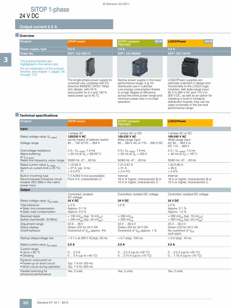
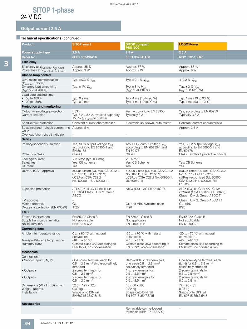
The single-phase power supply for universal use; complies with EU directive 94/9/EEC (ATEX 100a); slim design; with 50 %extra power for 5 s and 120 % rated power up to 45 °C
Narrow power supply in the lower performance range, e.g. for distributed use in cubicles. Low energy consumption thanks to a high degree of efficiency across the entire power range and minimum power loss in no-load operation.
LOGO!Power supplies are optimally matched in design and functionality to the LOGO! logic modules; with wide-range input 85 V to 264 V AC and 110 V to 300 V DC, as well as an option for installing in built-in miniature distribution boards, they can be used universally in the low-end performance range.
Product SITOP smart SITOP compactPSU100C
LOGO!Power
Input
1-phase AC 1-phase AC or DC 1-phase AC or DCRated voltage value Vin rated 120/230 V AC
set by means of selector switch100-230 V AC Wide-range input
100-240 V AC Wide-range input
Voltage range 85 ... 132 V/170 ... 264 V 85 ... 264 V AC or 110 ... 300 V DC AC 85 ... 264 V or DC 110 ... 300 V
Overvoltage resistance 2.3 × Vin rated, 1.3 ms 2.3 x Vin rated, 1.3 ms 2.3 × Vin rated, 1.3 msMains buffering at Iout rated
> 20 ms at Vin = 93/187 V > 20 ms at Vin = 230 V > 40 ms at Vin = 187 V
Rated line frequency value; range 50/60 Hz; 47 ... 63 Hz 50/60 Hz; 47 ... 63 Hz 50/60 Hz; 47 ... 63 Hz
Rated current value Iin rated 1.1/0.65 A 1.21-0.67 A 1.22-0.66 ASwitch-on current limit (+25 °C) < 27 A, typ. 3 ms < 31 A < 46 AI2t < 0.3 A2s < 2.4 A2s < 3 A2s
Built-in incoming fuse T 2 A/250 V (not accessible) Internal InternalRecommended miniature circuit breaker (IEC 898) in the mains power input
From 3 A, characteristic C 16 A or higher, characteristic B or 10 A or higher, characteristic C
16 A or higher, characteristic B or 10 A or higher, characteristic C
Output
Controlled, isolatedDC voltage
Controlled, isolated DC voltage Controlled, isolated DC voltage
Rated voltage value Vout rated 24 V DC 24 V DC 24 V DC
Total tolerance ± 3 % ± 3 % ± 3 %• Static line compensation Approx. 0.1 % Approx. 0.1 %• Static load compensation Approx. 0.5 % Approx. 1.5 %
Residual ripple < 150 mVpp (typ. 10 mVpp) < 200 mVpp < 200 mVpp (typ. 10 mVpp)Spikes (bandwidth: 20 MHz) < 240 mVpp (typ. 50 mVpp) < 300 mVpp < 300 mVpp (typ. 50 mVpp)
Adjustment range 22.8 ... 28 V 22.2 ... 26.4 V 22.2 ... 26.4 VStatus display Green LED for 24 V OK Green LED for 24 V OK Green LED for 24 V OKOn/off behavior Overshoot of Vout approx. 4% Overshoot of Vout approx. 1 % No overshoot of Vout
(soft start)
Startup delay/voltage rise < 0.1 s at 230 V AC/typ. 50 ms < 0.7 s/typ. 100 ms < 0.5 s/typ. 10 ms
Rated current value Iout rated 2.5 A 2.5 A 2.5 A
Current range • Up to + 60 °C 0 ... 2.5 A 0 ... 2.5 A (up to +50 °C) 0 ... 2.5 A (up to +55 °C)• Derating 0 ... 3 A (up to +45 °C) 0 ... 0.75 A (up to +70 °C) 0 ... 1.75 A (up to +70 °C)
Dynamic overcurrent on • Power-up on short circuit Typ. 7 A for 100 ms• Short circuit during operation Typ. 7 A for 200 ms
Parallel switching for enhanced performance
Yes, 2 units Yes, 2 units Yes, 2 units
NEW NEW
KT10_EN_gesamt.book Seite 2 Mittwoch, 12. Oktober 2011 11:00 11
© Siemens AG 2011

SITOP 1-phase24 V DC
Output current 2.5 A
3/3Siemens KT 10.1 · 2012
3
1) SIPLUS module see page 15/3
SITOP in SIMATIC designThe S7-1200 version
SITOP lite PSU100L
Special designPSU100D
Special designPSA100E
2.5 A 2.5 A 2.1 A 2.5 A
6EP1 332-1SH71 1) 6EP1 332-1LB00 6EP1 331-1LD00 6EP1 232-1AA00
The power supply PM1207 (Power Module) is optimized for the new SIMATIC S7-1200 controllers in terms of design and functionality and serves as an external supply for the inputs and outputs which, to prevent an imbalance, must not be drawn from the CPU encoder supply.
The low-cost power supply for standard requirements in industrial environments; slim design; wide-range input with manual switchover.
The low-cost power supply in flat aluminum housing can be screwed directly on a wall in various mounting positions; with wide-range input for global use.
The power supply is optimally tailored to standard requirements in the industrial environment; rugged metal enclosure; flexible mounting either on standard rails or directly on a wall; removable terminals.
SITOP in SIMATIC designThe S7-1200 version
SITOP lite PSU100L
Special designPSU100D
Special designPSA100E
1-phase AC 1-phase AC 1-phase AC 1-phase AC120/230 V ACAutomatic range switch-over
120/230 V ACset by means of selector switch
100-240 V ACWide-range input
230 V AC
85 ... 132 V/176 ... 264 V 85 ... 132 V/170 ... 264 V 85 ... 264 V 187 ... 264 V
2.3 x Vin rated, 1.3 ms 2.3 × Vin rated, 1.3 ms –> 20 ms at Vin = 93/187 V > 20 ms at Vin = 93/187 V > 15 ms at Vin = 115/230 V > 10 ms
50/60 Hz; 47 ... 63 Hz 50/60 Hz; 47 ... 63 Hz 50/60 Hz; 47 ... 63 Hz 50/60 Hz; 47 ... 63 Hz
1.2/0.67 A 1.1/0.65 A 1.1-0.7 A 0.65 A< 13 A, < 3 ms (Vin = 230 V) < 27 A, typ. 3 ms < 60 A < 30 A< 0.5 A2s < 0.3 A2s < 1.2 A2s < 0.8 A2s
T 3.15 A/250 V (not accessible) T 2 A/250 V (not accessible) Internal Internal16 A or higher, characteristic B or 10 A or higher, characteristic C
3 A or higher, characteristic C 16 A or higher, characteristic B or 10 A or higher, characteristic C
6 A or higher, characteristic C
Controlled, isolatedDC voltage
Controlled, isolatedDC voltage
Controlled, isolatedDC voltage
Controlled, isolatedDC voltage
24 V DC 24 V DC 24 V DC 24 V DC
± 3 % ± 3 % ±2 % ±3 %Approx. 0.1 % Approx. 0.1 % Approx. 0.5 % Approx. 0.1 %Approx. 0.2 % Approx. 0.5 % Approx. 1.0 % Approx. 0.5 %
< 150 mVpp < 150 mVpp (typ. 10 mVpp) < 100 mVpp < 150 mVpp< 240 mVpp < 240 mVpp (typ. 50 mVpp) < 100 mVpp < 250 mVpp
– 22.8 ... 26.4 V 22.0 ... 28.0 V 23 ... 26 V24 V OK = green LED Green LED for 24 V OK Green LED for 24 V OK Green LED for 24 V OKNo overshoot of Vout(soft start)
Overshoot of Vout approx. 4 % Overshoot of Vout <2% Overshoot of Vout <1 %
< 2 (6) s at 230 (120) V / typ. 10 ms < 1.5 s/typ. 150 ms < 1 s/< 30 ms < 1.5 s/< 100 ms
2.5 A 2.5 A 2.1 A 2.5 A
0 ... 2.5 A 0 ... 1.75 A 0 ... 2.1 A (up to + 50 °C) 0 ... 2.5 A (up to + 45 °C)– 0 ... 2.5 A (up to + 45 °C) 0 ... 1.0 A (up to + 70 °C) 0 ... 1.25 A (up to + 70 °C)
Typ. 6 A for 100 msTyp. 6 A for 100 ms
Yes, 2 units Yes, 2 units Yes, 2 units Yes, 2 units
NEW NEW
KT10_EN_gesamt.book Seite 3 Mittwoch, 12. Oktober 2011 11:00 11
© Siemens AG 2011
SITOP 1-phase24 V DC
Output current 2.5 A
3/4 Siemens KT 10.1 · 2012
3
■ Technical specifications (continued)
Product SITOP smart SITOP compactPSU100C
LOGO!Power
Power supply, type 2.5 A 2.5 A 2.5 A
Order No. 6EP1 332-2BA10 6EP1 332-5BA00 6EP1 332-1SH43
Efficiency
Efficiency at Vout rated, Iout rated Approx. 85 % Approx. 87 % Approx. 88 %Power loss at Vout rated, Iout rated Approx. 9 W Approx. 9 W Approx. 8 W
Closed-loop control
Dyn. mains compensation (Vin rated ± 15 %)
Typ. ± 0.3 % Vout Typ. ± 0.1 % Vout < 0.2 % Vout
Dynamic load smoothing(Iout: 50/100/50 %)
Typ. ± 1% Vout Typ. ± 3 % Vout(Iout: 10/90/10 %)
Typ. ± 2 % Vout(Iout: 10/90/10 %)
Load step settling time• 50 to 100% Typ. 0.2 ms Typ. 4 ms (10 to 90 %) Typ. 1 ms (10 to 90 %)• 100 to 50% Typ. 0.2 ms Typ. 4 ms (10 to 90 %) Typ. 1 ms (90 to 10 %)
Protection and monitoring
Output overvoltage protection <33 V Yes, according to EN 60950 Yes, according to EN 60950Current limitation Typ. 3.2 ... 3.4 A, overload capability
150 % Iout rated to 5 s/minTypically 3 A Typically 3.3 A
Short-circuit protection Constant current characteristic Electronic shutdown, auto restart Constant current characteristic
Sustained short-circuit current rms value
Approx. 5 A Approx. 3.5 A
Overload/short-circuit indicator – – –
Safety
Primary/secondary isolation Yes, SELV output voltage Vout according to EN 60950-1 and EN 50178
Yes, SELV output voltage Vout according to EN 60950-1 and EN 50178
Yes, SELV output voltage Vout according to EN 60950-1 and EN 50178
Protection class Class I Class I Class II (without protective cndct)
Leakage current < 3.5 mA (typ. 0.4 mA) < 3.5 mA –Safety test Yes; CB scheme Yes; CB Scheme Yes; CB SchemeCE mark Yes Yes Yes
UL/cUL (CSA) approval cULus-Listed (UL 508, CSA C22.2 No. 107.1), File E197259; cCSAus (CSA C22.2 No. 60950-1, UL 60950-1)
cULus-Listed (UL 508, CSA C22.2 No. 107.1), File E197259;cCSAus (CSA C22.2 No. 60950-1, UL 60950-1)
cULus-listed (UL 508, CSA C22.2 No. 107.1), File E197259; cURus-recognized (UL 60950, CSA C22.2 No. 60950), File E151273
Explosion protection ATEX (EX) II 3G Ex nA II T4; UL 1604 Class I, Div. 2. Group ABCD
ATEX (EX) II 3G Ex nA IIC T4 ATEX (EX) II 3G Ex nA IIC T3;cCSAus (CSA E60079, UL 60079), Class I, Div. 2. Group ABDC T4
FM approval – Class I, Div. 2. Group ABCD T4Marine approval GL GL and ABS available soon GL, ABSDegree of protection (EN 60529) IP20 IP20 IP20
EMC
Emitted interference EN 55022 Class B EN 55022 Class B EN 55022 Class BSupply harmonics limitation Not applicable Not applicable Not applicableNoise immunity EN 61000-6-2 EN 61000-6-2 EN 61000-6-2
Operating data
Ambient temperature range 0 ... + 60 °C with natural convection
-20 ... +70 °C with natural convection
-20 ... +70 °C with natural convection
Transport/storage temp. range -40 ... + 85 °C -40 ... +85 °C -40 ... +85 °CHumidity class Climate class 3K3 according to
EN 60721, no condensationClimate class 3K3 according to EN 60721, no condensation
Climate class 3K3 according to EN 60721, no condensation
Mechanics
Connections • Supply input L, N, PE One screw terminal each for
0.5 ... 2.5 mm2 single-core/finely stranded
Removable screw terminals, one each 0.5 ... 2.5 mm2 solid/finely stranded
One screw-type terminal each (L, N) for 0.5 ... 2.5 mm2 solid/finely stranded
• Output + 2 screw terminals for 0.5 ... 2.5 mm2
1 screw terminal for 0.5 ... 2.5 mm2
2 screw terminals for 0.5 ... 2.5 mm2
• Output – 2 screw terminals for 0.5 ... 2.5 mm2
2 screw terminals for 0.5 ... 2.5 mm2
2 screw terminals for 0.5 ... 2.5 mm2
Dimensions (W x H x D) in mm 32.5 × 125 × 125 45 x 80 x 100 72 × 90 × 55Weight, approx. 0.32 kg 0.22 kg 0.25 kgInstallation Snaps onto DIN rail
EN 60715 35x7.5/15Snaps onto DIN rail EN 60715 35x7.5/15
Snaps onto DIN rail EN 60715 35x7.5/15
Accessories
– Removable spring-loaded terminals (6EP1971-5BA00)
–
KT10_EN_gesamt.book Seite 4 Mittwoch, 12. Oktober 2011 11:00 11
© Siemens AG 2011

SITOP 1-phase24 V DC
Output current 2.5 A
3/5Siemens KT 10.1 · 2012
3
SITOP in SIMATIC designThe S7-1200 version
SITOP lite PSU100L
Special design PSU100D
Special designPSA100E
2.5 A 2.5 A 2.1 A 2.5 A
6EP1 332-1SH71 6EP1 332-1LB00 6EP1 331-1LD00 6EP1 232-1AA00
Approx. 83 % Approx. 85 % Approx. 86 % Approx. 84 %Approx. 12 W Approx. 9 W Approx. 8 W Approx. 11 W
Typ. ± 0.3 % Vout Typ. ± 0.3 % Vout Typ. ± 0.5 % Vout <0.3 % Vout
Typ. ± 0.3 % Vout Typ. ± 2 % Vout (Iout: 10/90/10 %) Typ. ±5.0 % Vout (0 to 100 %) Typ. ±2.0 % Vout
< 5 ms Typ. 0.5 ms (10 to 90 %) Typ. 0.2 ms< 5 ms Typ. 0.7 ms (90 to 10 %) Typ. 0.2 ms
< 33 V <33 V < 35 V < 35 V2.65 A Typically 2.6 A 2.5 A 3 A
Constant current characteristic Constant current characteristic Electronic shutdown, auto restart Electronic shutdown, auto restart
– Approx. 4 A Approx. 6 A < 2 A
– – – –
Yes, SELV output voltage Vout according to EN 60950-1 and EN 50178
Yes, SELV output voltage Vout according to EN 60950-1 and EN 50178
Yes, safety extra low output voltage Vout according to EN 60950-1
Yes, SELV output voltage Vout according to EN 60950-1 and EN 50178
Class I Class I Class I Class I
< 3.5 mA < 3.5 mA (typ. 0.4 mA) < 3.5 mA (typ. 1 mA) < 3.5 mA (typ. 0.4 mA)Yes Yes; CB Scheme in preparation Yes; CB Scheme in preparation Yes; CB SchemeYes Yes Yes Yes
cULus-Listed (UL 508, CSA C22.2 No. 107.1), File E197259; cULus-Recognized (UL 60950-1, CSA C22.2 No. 60950-1), File E151273
cULus-Listed (UL 508, CSA C22.2 No. 107.1) in preparation
cULus-Listed (UL 508, CSA C22.2 No. 107.1) in preparation, cURus (UL 60950-1, CSA C22.2 No. 60950-1) in preparation
cULus-listed (UL 508, CSA C22.2 No. 107.1), File E197259
ATEX (EX) II 3G Ex nA T4 – – –
– – – –GL, ABS, DNV, NK, BV, LRS – – –IP20 IP20 IP20 IP20
EN 55022 Class B EN 55022 Class A EN 55022 Class B EN 55022 Class BNot applicable Not applicable Not applicable Not applicableEN 61000-6-2 EN 61000-6-2 EN 61000-6-2 EN 61000-6-2
0 ... + 60 °C with natural convection
0 ... + 60 °C with natural convection
-10 ... +70 °C with natural convection
-10 ... +70 °C with natural convection
-40 ... + 85 °C -40 ... + 85 °C -25 ... +85 °C -40 ... +85 °CClimate class 3K3 according to EN 60721, no condensation
Climate class 3K3 according to EN 60721, no condensation
Climate class 3K3 according to EN 60721, no condensation
One screw terminal each for 0.5 ... 2.5 mm2
One screw-type terminal each for0.5 ... 2.5 mm2 solid/finely stranded
One screw-type terminal each for 0.3 ... 1.3 mm2 solid/finely stranded
Removable screw terminal, each 1 x 0.5 ... 2.5 mm2
2 screw terminals for 0.5 ... 2.5 mm2
2 screw terminals for 0.5 ... 2.5 mm2
1 screw terminal for 0.3 ... 1.3 mm2 solid/finely stranded
Removable screw terminal, each 1 x 0.5 ... 2.5 mm2
2 screw terminals for 0.5 ... 2.5 mm2
2 screw terminals for 0.5 ... 2.5 mm2
1 screw terminal for 0.3 ... 1.3 mm2 solid/finely stranded
Removable screw terminal, each 1 x 0.5 ... 2.5 mm2
70 x 100 x 75 32.5 × 125 × 125 97 x 128 x 38 52 x 170 x 1100.3 kg 0.32 kg 0.35 kg 0.8 kgSnaps onto DIN rail EN 60715 35x7.5/15. Wall mounting
Snaps onto DIN rail EN 60715 35x7.5/15
Wall mounting Snaps onto DIN rail EN 60715 35x7.5/15. Wall mounting
– – – –
KT10_EN_gesamt.book Seite 5 Mittwoch, 12. Oktober 2011 11:00 11
© Siemens AG 2011

SITOP 1-phase24 V DC
Output current 2.5 A
3/6 Siemens KT 10.1 · 2012
3
■ Selection and ordering data
■ Further information
Additional information is available in the Internet under:• 2D dimensional drawings, 3D CAD data, circuit diagram
macros: www.siemens.com/sitop-cax
• Operating instructions:www.siemens.de/sitop-manuals
• Find the right product with the SITOP Selection Tool: www.siemens.com/sitop-selection-tool
Product Input Output Order No. Price
Voltage Vin rated Voltage Vout rated Current Iout rated
SITOP smart
120/230 V AC 24 V DC 2.5 A 6EP1 332-2BA10
SITOP compact, PSU100C
100-230 V AC 24 V DC 2.5 A 6EP1 332-5BA00
LOGO!Power
100-240 V AC 24 V DC 2.5 A 6EP1 332-1SH43
SITOP in SIMATIC design, S7-1200 version
120/230 V AC 24 V DC 2.5 A 6EP1 332-1SH71
SITOP lite, PSU100L (Planned delivery date: November 2011)
120/230 V AC 24 V DC 2.5 A 6EP1 332-1LB00
Special design, PSU100D (Planned delivery date: December 2011)
100-240 V AC 24 V DC 2.1 A 6EP1 331-1LD00
Special design, PSA100E
230 V AC 24 V DC 2.5 A 6EP1 232-1AA00
NEW
NEW
NEW
NEW
KT10_EN_gesamt.book Seite 6 Mittwoch, 12. Oktober 2011 11:00 11
© Siemens AG 2011
Siemens KT 10.1 · 2012
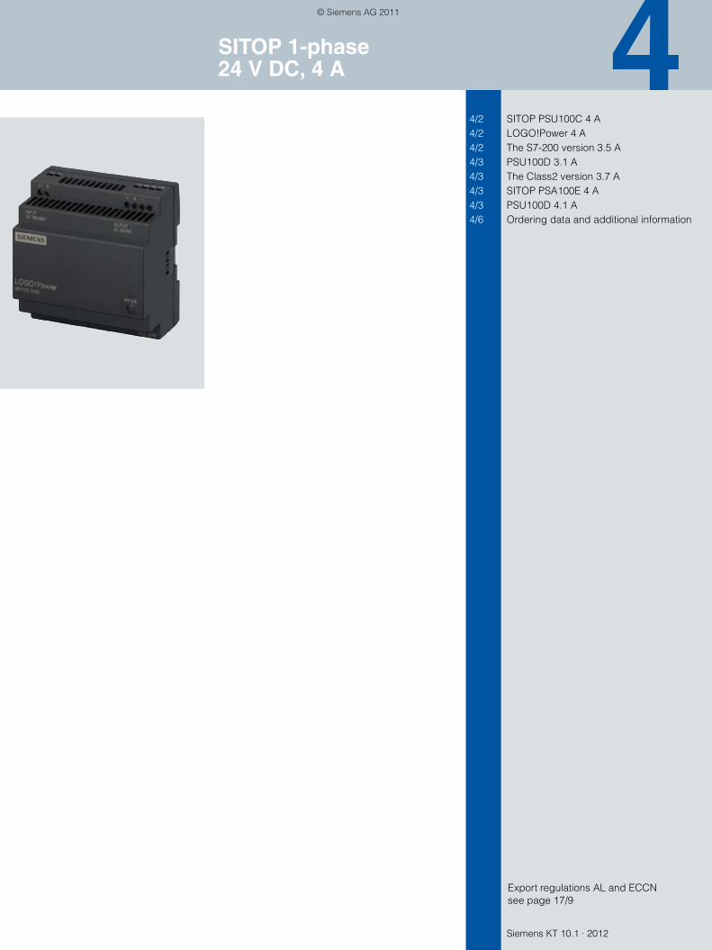
44/2 SITOP PSU100C 4 A4/2 LOGO!Power 4 A4/2 The S7-200 version 3.5 A4/3 PSU100D 3.1 A4/3 The Class2 version 3.7 A4/3 SITOP PSA100E 4 A4/3 PSU100D 4.1 A4/6 Ordering data and additional information
SITOP 1-phase24 V DC, 4 A
Export regulations AL and ECCNsee page 17/9
KT10_EN_gesamt.book Seite 1 Mittwoch, 12. Oktober 2011 11:00 11
© Siemens AG 2011

SITOP 1-phase24 V DC
Output current 4 A
4/2 Siemens KT 10.1 · 2012
4
■ Overview
■ Technical specifications
1) SIPLUS module see page 15/3.
Product SITOP compact PSU100C
LOGO!Power SITOP in SIMATIC design The S7-200 version
Power supply, type 4 A 4 A 3.5 A
Order No. 6EP1 332-5BA10 6EP1 332-1SH52 6EP1 332-1SH31 1)
The product families are highlighted in the same color.For an explanation of the product families, see chapter 1, pages 1/8 through 1/12.
Narrow power supply in the lower performance range, e.g. for distributed use in cubicles. Low energy consumption thanks to a high degree of efficiency across the entire power range and minimum power loss in no-load operation.
LOGO!Power supplies are optimally matched in design and functionality to the LOGO! logic modules; with wide-range input 85 V to 264 V AC and 110 V to 300 V DC, as well as an option for installing in built-in miniature distribution boards, they can be used universally in the low-end performance range.
Optimally matched in design and functionality to the SIMATIC S7-200 micro PLC; flat design, particularly suitable for low cabinet depths.
Product SITOP compactPSU100C
LOGO!Power SITOP in SIMATIC design The S7-200 version
Input
1-phase AC or DC 1-phase AC or DC 1-phase ACRated voltage value Vin rated 100-230 V AC
wide-range input100-240 V AC Wide-range input
120/230 V AC Set with wire jumper
Voltage range 85 ... 264 V AC or 110 ... 300 V DC AC 85 ... 264 VDC 110 … 300 V
93 ... 132 V/187 ... 264 V
Overvoltage resistance 2.3 x Vin rated, 1.3 ms 2.3 × Vin rated, 1.3 ms 2.3 × Vin rated, 1.3 msMains buffering at Iout rated > 20 ms at Vin = 230 V > 40 ms at Vin = 187 V > 20 ms at Vin = 187 V Rated line frequency value; range 50/60 Hz; 47 ... 63 Hz 50/60 Hz; 47 ... 63 Hz 50/60 Hz; 47 ... 63 Hz
Rated current Iin rated 0.28-0.18 A 1.95-0.97 A 1.65/0.95 ASwitch-on current limit (+25 °C) < 35 A < 30 A < 33 A, < 3 ms (Vin = 230 V)I2t < 3 A2s < 2.5 A2s < 1.0 A2s
Built-in incoming fuse Internal Internal T 2.5 A/250 V (not accessible)Recommended miniature circuit breaker (IEC 898) in the mains power input
16 A or higher, characteristic B or 10 A or higher, characteristic C
16 A or higher, characteristic B or 10 A or higher, characteristic C
Two-pole miniature circuit breaker, 10 A or higher, characteristic C or 6 A or higher, characteristic D
Output
Controlled, isolated DC voltage Controlled, isolated DC voltage Controlled, isolated DC voltageRated voltage Vout rated 24 V DC 24 V DC 24 V DC
Total tolerance ± 3 % ± 3 % ± 5 % (typ. ± 2 %)• Static line compensation Approx. 0.1 % Approx. 0.1 %• Static load compensation Approx. 1.5 % Approx. 0.2 %
Residual ripple < 200 mVpp < 200 mVpp (typ. 30 mVpp) < 150 mVpp (typ. 30 mVpp)Spikes (bandwidth: 20 MHz) < 300 mVpp < 300 mVpp (typ. 60 mVpp) < 240 mVpp (typ. 110 mVpp)
Adjustment range 22.2 ... 26.4 V 22.2 ... 26.4 V –Status display Green LED for 24 V OK Green LED for 24 V OK –On/off behavior Overshoot of Vout approx. 1 % No overshoot of Vout
(soft start)No overshoot of Vout(soft start)
Startup delay/voltage rise < 1 s/typ. 500 ms < 0.5 s/typ. 15 ms < 1 s/typ. 80 msRated current value Iout rated 4 A 4 A 3.5 A
Current range • Up to +60 °C 0 ... 4 A (up to +50 °C) 0 ... 4 A (up to +55 °C) 0 ... 3.5 A • Derating 0 ... 1.2 A (up to +70 °C) 0 ... 2.8 A (up to +70 °C) –
Dynamic overcurrent on • Power-up on short circuit Typ. 5 A for 100 ms• Short circuit during operation Typ. 5 A for 100 ms
Parallel switching for enhanced performance
Yes, 2 units Yes, 2 units Yes, up to 5 units
NEW NEW
KT10_EN_gesamt.book Seite 2 Mittwoch, 12. Oktober 2011 11:00 11
© Siemens AG 2011

SITOP 1-phase24 V DC
Output current 4 A
4/3Siemens KT 10.1 · 2012
4
2) Only permissible at ambient temperature 0 °C to +50 °C.
Special design PSU100D
Special designThe Class2 version
Special designPSA100E
Special design PSU100D
3.1 A 3.7 A 4 A 4.1 A
6EP1 332-1LD00 6EP1 332-2BA00 6EP1 232-1AA10 6EP1 332-1LD10
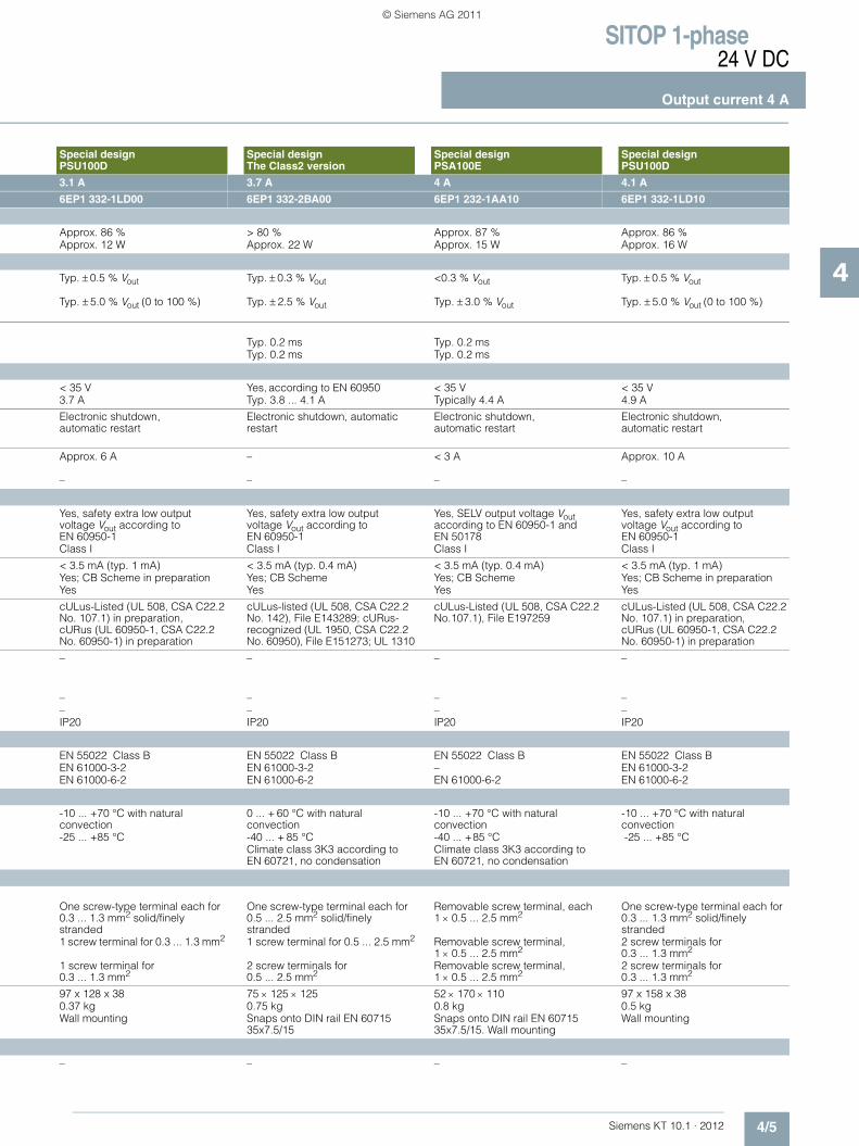
The low-cost power supply in flat aluminum housing can be screwed directly on a wall in various mounting positions; with wide-range input for global use.
The Class2 version with output limited to 100 W maximum.
The power supply is optimally tailored to standard requirements in the industrial environment; rugged metal enclosure; flexible mounting either on standard rails or directly on a wall; removable terminals.
The low-cost power supply in flat aluminum housing can be screwed directly on a wall in various mounting positions; with wide-range input for global use.
Special designPSU100D
Special designThe Class2 version
Special designPSA100E
Special designPSU100D
1-phase AC 1-phase AC 1-phase AC 1-phase AC100-240 V AC Wide-range input
120/230 V AC Set via wire jumper
230 V AC 120-240 V AC Wide-range input
85 ... 264 V 93 ... 132 V/187 ... 264 V 187 ... 264 V 85 ... 264 V
2.3 × Vin rated, 1.3 ms –> 15 ms at Vin = 115/230 V > 10 ms at Vin = 93/187 V > 10 ms > 15 ms at Vin = 115/230 V 50/60 Hz; 47 ... 63 Hz 50/60 Hz; 47 ... 63 Hz 50/60 Hz; 47 ... 63 Hz 50/60 Hz; 47 ... 63 Hz
1.5-1.0 A 1.8/0.7 A 1.1 A 2.0-1.1 A< 60 A < 32 A, typ. 3 ms (Vin = 230 V) < 30 A < 75 A1.2 A2s < 0.8 A2s < 0.8 A2s 4 A2s
Internal T 3.15 A/250 V (not accessible) Internal Internal10 A or higher, characteristic C or 16 A, characteristic B
From 6 A, characteristic C From 6 A, characteristic C 10 A or higher, characteristic C or 16 A, characteristic B
Controlled, isolated DC voltage Controlled, isolated DC voltage Controlled, isolated DC voltage Controlled, isolated DC voltage24 V DC 24 V DC 24 V DC 24 V DC
± 2 % ± 3 % ± 3 % ± 2 %Approx. 0.5 % Approx. 0.1 % Approx. 0.1 % Approx. 0.5 %Approx. 1.0 % Approx. 0.2 % Approx. 0.5 % Approx. 1.0 %
< 100 mVpp < 150 mVpp < 150 mVpp < 100 mVpp< 100 mVpp < 240 mVpp < 250 mVpp < 100 mVpp
22.0 ... 28.0 V 22.8 ... 26.4 V2) 23 ... 26 V 22.0 ... 28.0 V Green LED for 24 V OK Green LED for 24 V OK Green LED for 24 V OK Green LED for 24 V OKOvershoot of Vout < 2 % No overshoot of Vout
(soft start)Overshoot of Vout < 1 % Overshoot of Vout < 2 %
< 2.5 s/< 30 ms < 3 s/typ. 80 ms < 1.5 s/< 200 ms < 1 s/< 30 ms3.1 A 3.7 A 4 A 4.1 A
0 ... 3.1 A (up to +50 °C) 0 ... 3.7 A 0 ... 4 A (up to +45 °C) 0 ... 4.1 A (up to +50 °C)0 ... 1.5 A (up to +70 °C) – 0 ... 2 A (up to +70 °C) 0 ... 2.0 A (up to +70 °C)
Yes, 2 units Yes, 2 units 2) Yes, 2 units Yes, 2 units
NEW NEW
KT10_EN_gesamt.book Seite 3 Mittwoch, 12. Oktober 2011 11:00 11
© Siemens AG 2011

SITOP 1-phase24 V DC
Output current 4 A
4/4 Siemens KT 10.1 · 2012
4
■ Technical specifications (continued)
Product SITOP compact PSU100C
LOGO!Power SITOP in SIMATIC design The S7-200 version
Power supply, type 4 A 4 A 3.5 A
Order No. 6EP1 332-5BA10 6EP1 332-1SH52 6EP1 332-1SH31
Efficiency
Efficiency at Vout rated, Iout rated Approx. 88 % Approx. 89 % Approx. 84 %Power loss at Vout rated, Iout rated Approx. 13 W Approx. 12 W Approx. 16 W
Closed-loop control
Dyn. mains compensation (Vin rated ± 15 %)
<0.1 % Vout <0.2 % Vout Typ. ± 0.3 % Vout
Dynamic load smoothing(Iout: 50/100/50 %)
Typ. ± 3 % Vout(Iout: 10/90/10 %)
Typ. ± 1.5 % Vout(Iout: 10/90/10 %)
Typ. ± 3 % Vout
Load step settling time • 50 to 100 % Typ. 4 ms (10 to 90 %) Typ. 1 ms (10 to 90 %) < 5 ms• 100 to 50 % Typ. 4 ms (90 to 10%) Typ. 1 ms (90 to 10%) < 5 ms
Protection and monitoring
Output overvoltage protection Yes, according to EN 60950 Yes, according to EN 60950 Yes, according to EN 60950Current limitation Typically 4.8 A Typically 5.2 A 3.8 A
Short-circuit protection Electronic shutdown, automatic restart
Constant current characteristic Constant current characteristic up to typ. 14 V, electronic shutdown below that, automatic restart
Sustained short-circuit current rms value
< 7.9 A < 4 A
Overload/short-circuit indicator – – –
Safety
Primary/secondary isolation Yes, SELV output voltage Vout according to EN 60950-1 and EN 50178
Yes, SELV output voltage Vout according to EN 60950-1 and EN 50178
Yes, safety extra low output voltage Vout according to EN 60950-1
Protection class Class I Class II (without protective cndct) Class I
Leakage current < 3.5 mA – < 3.5 mASafety test Yes; CB scheme Yes; CB Scheme YesCE mark Yes Yes Yes
UL/cUL (CSA) approval cULus-Listed (UL 508, CSA C22.2 No. 107.1), File E197259;cCSAus (CSA C22.2 No. 60950-1, UL 60950-1)
cULus-Listed (UL 508, CSA C22.2 No. 107.1), File E197259; cURus-Recognized (UL 60950, CSA C22.2 No. 60950), File E151273
cULus-Listed (UL 508, CSA C22.2 No. 142), File E143289
Explosion protection ATEX (EX) II 3G Ex nA IIC T4 ATEX (EX) II 3G Ex nA IIC T3;cCSAus (CSA E60079, UL 60079), Class I, Div. 2. Group ABCD, T4
–
FM approval Class I, Div. 2. Group ABCD, T4 –Marine approval GL and ABS available soon GL, ABS –Degree of protection (EN 60529) IP20 IP20 IP20
EMC
Emitted interference EN 55022 Class B EN 55022 Class B EN 55022 Class BSupply harmonics limitation EN 61000-3-2 EN 61000-3-2 EN 61000-3-2Noise immunity EN 61000-6-2 EN 61000-6-2 EN 61000-6-2
Operating data
Ambient temperature range -20 ... +70 °C with natural convection – 20 ... +70 °C with natural convection
0 ... + 60 °C with natural convection
Transport/storage temperature range -40 ... +85 °C – 40 ... +85 °C – 40 ... + 85 °CHumidity class Climate class 3K3 according to
EN 60721, no condensationClimate class 3K3 according to EN 60721, no condensation
Climate class 3K3 according to EN 60721, no condensation
Mechanics
Connections • Supply input L, N, PE Removable screw terminals, one
each 0.5 ... 2.5 mm2 solid/finely stranded
One screw-type terminal each (L, N) for 0.5 ... 2.5 mm2 solid/finely stranded
One screw-type terminal each for 0.5 ... 1.5 mm2 solid/finely stranded
• Output + 1 screw terminal for 0.5 ... 2.5 mm2 2 screw terminals for 0.5 to 2.5 mm2 1 screw terminal for 0.5 ... 1 mm2
• Output – 2 screw terminals for 0.5 ... 2.5 mm2
2 screw terminals for 0.5 to 2.5 mm2
2 screw terminals for 0.5 ... 1 mm2
Dimensions (W x H x D) in mm 52.5 x 80 x 100 90 × 90 × 55 160 × 80 × 62Weight, approx. 0.32 kg 0.34 kg 0.5 kgInstallation Snaps onto DIN rail
EN 60715 35x7.5/15Snaps onto DIN railEN 60715 35x7.5/15
Snaps onto DIN rail EN 60715 35x7.5/15. Wall mounting
Accessories
Removable spring-loaded terminals(6EP1971-5BA00)
–
KT10_EN_gesamt.book Seite 4 Mittwoch, 12. Oktober 2011 11:00 11
© Siemens AG 2011
SITOP 1-phase24 V DC
Output current 4 A
4/5Siemens KT 10.1 · 2012
4
Special design PSU100D
Special designThe Class2 version
Special designPSA100E
Special design PSU100D
3.1 A 3.7 A 4 A 4.1 A
6EP1 332-1LD00 6EP1 332-2BA00 6EP1 232-1AA10 6EP1 332-1LD10
Approx. 86 % > 80 % Approx. 87 % Approx. 86 %Approx. 12 W Approx. 22 W Approx. 15 W Approx. 16 W
Typ. ± 0.5 % Vout Typ. ± 0.3 % Vout <0.3 % Vout Typ. ± 0.5 % Vout
Typ. ± 5.0 % Vout (0 to 100 %) Typ. ± 2.5 % Vout Typ. ± 3.0 % Vout Typ. ± 5.0 % Vout (0 to 100 %)
Typ. 0.2 ms Typ. 0.2 msTyp. 0.2 ms Typ. 0.2 ms
< 35 V Yes, according to EN 60950 < 35 V < 35 V3.7 A Typ. 3.8 ... 4.1 A Typically 4.4 A 4.9 A
Electronic shutdown,automatic restart
Electronic shutdown, automatic restart
Electronic shutdown, automatic restart
Electronic shutdown, automatic restart
Approx. 6 A – < 3 A Approx. 10 A
– – – –
Yes, safety extra low output voltage Vout according to EN 60950-1
Yes, safety extra low output voltage Vout according to EN 60950-1
Yes, SELV output voltage Vout according to EN 60950-1 and EN 50178
Yes, safety extra low output voltage Vout according to EN 60950-1
Class I Class I Class I Class I
< 3.5 mA (typ. 1 mA) < 3.5 mA (typ. 0.4 mA) < 3.5 mA (typ. 0.4 mA) < 3.5 mA (typ. 1 mA) Yes; CB Scheme in preparation Yes; CB Scheme Yes; CB Scheme Yes; CB Scheme in preparationYes Yes Yes Yes
cULus-Listed (UL 508, CSA C22.2 No. 107.1) in preparation, cURus (UL 60950-1, CSA C22.2 No. 60950-1) in preparation
cULus-listed (UL 508, CSA C22.2 No. 142), File E143289; cURus-recognized (UL 1950, CSA C22.2 No. 60950), File E151273; UL 1310
cULus-Listed (UL 508, CSA C22.2 No.107.1), File E197259
cULus-Listed (UL 508, CSA C22.2 No. 107.1) in preparation, cURus (UL 60950-1, CSA C22.2 No. 60950-1) in preparation
– – – –
– – – –– – – –IP20 IP20 IP20 IP20
EN 55022 Class B EN 55022 Class B EN 55022 Class B EN 55022 Class BEN 61000-3-2 EN 61000-3-2 – EN 61000-3-2EN 61000-6-2 EN 61000-6-2 EN 61000-6-2 EN 61000-6-2
-10 ... +70 °C with natural convection
0 ... + 60 °C with natural convection
-10 ... +70 °C with natural convection
-10 ... +70 °C with natural convection
-25 ... +85 °C -40 ... + 85 °C -40 ... +85 °C -25 ... +85 °CClimate class 3K3 according to EN 60721, no condensation
Climate class 3K3 according to EN 60721, no condensation
One screw-type terminal each for 0.3 ... 1.3 mm2 solid/finely stranded
One screw-type terminal each for 0.5 ... 2.5 mm2 solid/finely stranded
Removable screw terminal, each 1 × 0.5 ... 2.5 mm2
One screw-type terminal each for 0.3 ... 1.3 mm2 solid/finely stranded
1 screw terminal for 0.3 ... 1.3 mm2 1 screw terminal for 0.5 ... 2.5 mm2 Removable screw terminal, 1 × 0.5 ... 2.5 mm2
2 screw terminals for 0.3 ... 1.3 mm2
1 screw terminal for 0.3 ... 1.3 mm2
2 screw terminals for 0.5 ... 2.5 mm2
Removable screw terminal, 1 × 0.5 ... 2.5 mm2
2 screw terminals for 0.3 ... 1.3 mm2
97 x 128 x 38 75 × 125 × 125 52 × 170 × 110 97 x 158 x 380.37 kg 0.75 kg 0.8 kg 0.5 kgWall mounting Snaps onto DIN rail EN 60715
35x7.5/15Snaps onto DIN rail EN 60715 35x7.5/15. Wall mounting
Wall mounting
– – – –
KT10_EN_gesamt.book Seite 5 Mittwoch, 12. Oktober 2011 11:00 11
© Siemens AG 2011

SITOP 1-phase24 V DC
Output current 4 A
4/6 Siemens KT 10.1 · 2012
4
■ Selection and ordering data
■ Further information
Additional information is available in the Internet under:• 2D dimensional drawings, 3D CAD data, circuit diagram
macros: www.siemens.com/sitop-cax
• Operating instructions:www.siemens.de/sitop-manuals
• Find the right product with the SITOP Selection Tool: www.siemens.com/sitop-selection-tool
Product Input Output Order No. Price
Voltage Vin rated Voltage Vout rated Current Iout rated
SITOP compact, PSU100C
100-230 V AC 24 V DC 4 A 6EP1 332-5BA10
LOGO!Power
100-240 V AC 24 V DC 4 A 6EP1 332-1SH52
SITOP in SIMATIC design, The S7-200 version
120/230 V AC 24 V DC 3.5 A 6EP1 332-1SH31
Special design, The Class2 version
120/230 V AC 24 V DC 3.7 A 6EP1 332-2BA00
Special design, PSU100D(Planned delivery date: December 2011)
100-240 V AC 24 V DC 3.1 A 6EP1 332-1LD00
Special design, PSA100E
230 V AC 24 V DC 4 A 6EP1 232-1AA10
Special design, PSU100D(Planned delivery date: December 2011)
100-240 V AC 24 V DC 4.1 A 6EP1 332-1LD10
NEW
NEW
NEW
NEW
KT10_EN_gesamt.book Seite 6 Mittwoch, 12. Oktober 2011 11:00 11
© Siemens AG 2011
Siemens KT 10.1 · 2012
55/2 SITOP modular 5 A5/2 SITOP smart 5 A5/3 SITOP PSU100L 5 A5/3 The S7-300 version 5 A5/3 The outdoor version 5 A5/3 The flat design 5 A5/6 Ordering data and additional information
SITOP 1-phase and 2-phase24 V DC, 5 A
Export regulations AL and ECCNsee page 17/9
KT10_EN_gesamt.book Seite 1 Mittwoch, 12. Oktober 2011 11:00 11
© Siemens AG 2011
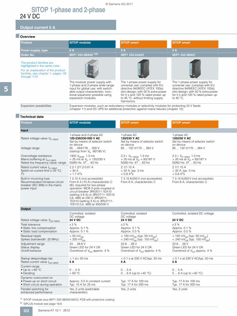
SITOP 1-phase and 2-phase24 V DC
Output current 5 A
5/2 Siemens KT 10.1 · 2012
5
■ Overview
■ Technical data
1) SITOP modular plus 6EP1 333-3BA00-8AC0, PCB with protective coating.2) SIPLUS module see page 15/3.
Product SITOP modular SITOP smart SITOP smart
Power supply, type 5 A 5 A 5 A
Order No. 6EP1 333-3BA00 1)2) 6EP1 333-2AA01 6EP1 333-2BA01
The product families are highlighted in the same color.For an explanation of the product families, see chapter 1, pages 1/8 through 1/12.
The modular power supply with 1-phase and 2-phase wide-range input for global use; with switch-able output characteristic; func-tional expansion possible using expansion modules.
The 1-phase power supply for universal use; complies with EU directive 94/9/EEC (ATEX 100a); slim design; with 50 % extra power for 5 s and 120 % rated power up to 45 °C; without limiting supply harmonics.
The 1-phase power supply for universal use; complies with EU directive 94/9/EEC (ATEX 100a); slim design; with 50 % extra power for 5 s and 120 % rated power up to 45 °C.
Expansion possibilities Expansion modules, such as redundancy modules or selectivity modules for protecting 24 V feeds(chapter 11) and DC UPS for additional protection against mains failures (chapter 12)
Product SITOP modular SITOP smart SITOP smart
Input
1-phase and 2-phase AC 1-phase AC 1-phase ACRated voltage value Vin rated 120-230/230-500 V AC
Set by means of selector switch on device
120/230 V ACSet by means of selector switchon device
120/230 V ACSet by means of selector switchon device
Voltage range 85 ... 264/176 ... 500 V (startup from Vin 90/180 V)
85 ... 132 V/170 ... 264 V 85 ... 132 V/170 ... 264 V
Overvoltage resistance 1300 Vpeak, 1.3 ms 2.3 × Vin rated, 1.3 ms 2.3 × Vin rated, 1.3 ms Mains buffering at Iout rated > 25 ms at Vin = 120/230 V > 20 ms at Vin = 93/187 V > 20 ms at Vin = 93/187 V Rated line frequency value; range 50/60 Hz; 47 ... 63 Hz 50/60 Hz; 47 ... 63 Hz 50/60 Hz; 47 ... 63 Hz
Rated current value Iin rated 2.2-1.2/1.2-0.61 A 2.1/1.15 A 2.1/1.15 ASwitch-on current limit (+25 °C) < 35 A < 32 A, typ. 3 ms < 32 A, typ. 3 msI2t < 1.7 A2s < 0.8 A2s < 0.8 A2s
Built-in incoming fuse T 3.15 A (not accessible) T 3.15 A/250 V (not accessible) T 3.15 A/250 V (not accessible)Recommended miniature circuit breaker (IEC 898) in the mains power input
From 6 A (10 A) characteristic C (B); required for two-phase operation: MCB 2-pole coupled or circuit-breaker 3RV2011-1EA10 (setting 3.8 A) or 3RV2711-1ED10 (UL 489) at 230 V; 3RV2011-1DA10 (setting 3 A) or 3RV2711-1DD10 (UL 489) at 400/500 V
From 6 A, characteristic C From 6 A, characteristic C
Output
Controlled, isolated DC voltage
Controlled, isolatedDC voltage
Controlled, isolated DC voltage
Rated voltage value Vout rated 24 V DC 24 V DC 24 V DC
Total tolerance ± 3 % ± 3 % ± 3 %• Static line compensation Approx. 0.1 % Approx. 0.1 % Approx. 0.1 %• Static load compensation Approx. 0.1 % Approx. 0.5 % Approx. 0.5 %
Residual ripple < 50 mVpp < 150 mVpp (typ. 50 mVpp) < 150 mVpp (typ. 50 mVpp)Spikes (bandwidth: 20 MHz) < 200 mVpp < 240 mVpp (typ. 150 mVpp) < 240 mVpp (typ. 150 mVpp)
Adjustment range 24 ... 28.8 V 22.8 ... 28 V 22.8 ... 28 VStatus display Green LED for 24 V OK Green LED for 24 V OK Green LED for 24 V OKOn/off behavior Overshoot of Vout approx. 3 % Overshoot of Vout approx. 4 % Overshoot of Vout approx. 4 %
Startup delay/voltage rise < 1 s/< 50 ms < 0.1 s at 230 V AC/typ. 50 ms < 0.1 s at 230 V AC/typ. 50 msRated current value Iout rated 5 A 5 A 5 A
Current range • Up to + 60 °C 0 ... 5 A 0 ... 5 A 0 ... 5 A • Derating > 60 °C 0 ... 6 A (up to +45 °C) 0 ... 6 A (up to +45 °C)
Dynamic overcurrent on • Power-up on short circuit Approx. 5.5 A constant current Typ. 17 A for 100 ms Typ. 17 A for 100 ms• Short circuit during operation Typ. 15 A for 25 ms Typ. 17 A for 200 ms Typ. 17 A for 200 ms
Parallel switching for enhanced performance
Yes, 2 units (switchable characteristic)
Yes, 2 units Yes, 2 units
KT10_EN_gesamt.book Seite 2 Mittwoch, 12. Oktober 2011 11:00 11
© Siemens AG 2011

SITOP 1-phase and 2-phase24 V DC
Output current 5 A
5/3Siemens KT 10.1 · 2012
5
SITOP lite PSU100L
SITOP in SIMATIC designThe S7-300 version
SITOP in SIMATIC designThe outdoor version
Special designThe flat design
5 A 5 A 5 A 5 A
6EP1 333-1LB00 6ES7 307-1EA01-0AA0 6ES7 307-1EA80-0AA0 2) 6EP1 333-1AL12
The low-cost power supply for standard requirements in industrial environments; slim design; wide-range input with manual switchover.
The proven power supply in SIMATIC S7-300 design; with PS-CPU connecting comb and for mounting direct on S7 rail.
The power supply unit for extreme environmental conditions in SIMATIC S7-300 design; can be snapped onto S7 rail; with PS-CPU connecting comb.
The flat design is of great advantage where only low mounting depths are available, e.g. for use with distributed I/O, in machine benches or alcoves; design matched to SIMATIC ET 200B.
Expansion modules, such as redundancy modules or selectivity modules for protecting 24 V feeds(chapter 11) and DC UPS for additional protection against mains failures (chapter 12)
SITOP lite PSU100L
SITOP in SIMATIC designThe S7-300 version
SITOP in SIMATIC designThe outdoor version
Special designThe flat design
1-phase AC 1-phase AC 1-phase AC 1-phase AC120/230 V ACSet by means of selector switchon device
120/230 V ACAutomatic range switch-over
120/230 V ACSet by means of selector switchon device
120/230 V ACSet by means of selector switchon device
85 ... 132 V/170 ... 264 V 85 ... 132 V/170 ... 264 V 93 ... 132 V/187 ... 264 V 85 ... 132 V/170 ... 264 V
2.3 × Vin rated, 1.3 ms 2.3 × Vin rated, 1.3 ms 2.3 × Vin rated, 1.3 ms 2.3 × Vin rated, 1.3 ms> 20 ms at Vin = 93/187 V > 20 ms at Vin = 93/187 V > 20 ms at Vin = 93/187 V > 20 ms at Vin = 93/187 V 50/60 Hz; 47 ... 63 Hz 50/60 Hz; 47 ... 63 Hz 50/60 Hz; 47 ... 63 Hz 50/60 Hz; 47 ... 63 Hz
2.1/1.15 A 2.3/1.2 A 2.1/1.2 A 2.2/1.2 A< 32 A, typ. 3 ms < 20 A, < 3 ms < 45 A, < 3 ms < 32 A, < 3 ms< 0.8 A2s < 1.2 A2s < 1.8 A2s (typ. 1.2 A2s) < 0.8 A2s
T 3.15 A/250 V (not accessible) T 3.15 A/250 V (not accessible) T 3.15 A/250 V (not accessible) T 3.15 A/250 V (not accessible)From 6 A, characteristic C From 6 A, characteristic C 10 A or higher, characteristic C or
6 A or higher, characteristic DFrom 6 A, characteristic C
Controlled, isolated DC voltage
Controlled, isolatedDC voltage
Controlled, isolated DC voltage Controlled, isolated DC voltage
24 V DC 24 V DC 24 V DC 24 V DC
± 3 % ± 3 % ± 3 % ± 1 %Approx. 0.1 % Approx. 0.1 % Approx. 0.2 % Approx. 0.1 %Approx. 0.5 % Approx. 0.5 % Approx. 0.4 % Approx. 0.5 %
< 150 mVpp (typ. 50 mVpp) < 50 mVpp (typ. 10 mVpp) < 150 mVpp (typ. 40 mVpp) < 150 mVpp (typ. 40 mVpp)< 240 mVpp (typ. 150 mVpp) < 150 mVpp (typ. 20 mVpp) < 240 mVpp (typ. 90 mVpp) < 240 mVpp (typ. 100 mVpp)
22.8 ... 26.4 V – – 22 ... 29 VGreen LED for 24 V OK Green LED for 24 V OK Green LED for 24 V OK Green LED for 24 V OKOvershoot of Vout approx. 4 % No overshoot of Vout
(soft start)No overshoot of Vout(soft start)
No overshoot of Vout(soft start)
< 1.5 s/typ. 130 ms < 2 s/typ. 10 ms < 3 s/typ. 100 ms < 2 s/typ. 40 ms5 A 5 A 5 A 5 A
0 ... 3.5 A 0 ... 5 A 0 ... 5 A 0 ... 5 A 0 ... 5 A (up to +45 °C) – 0 ... 5 A (up to +70 °C) –
Typ. 20 A for 100 ms Typ. 20 A for 180 ms Typ. 20 A for 500 msTyp. 20 A for 100 ms Typ. 20 A for 80 ms Typ. 20 A for 500 ms
Yes, 2 units Yes Not permitted Yes, 2 units
NEW
KT10_EN_gesamt.book Seite 3 Mittwoch, 12. Oktober 2011 11:00 11
© Siemens AG 2011
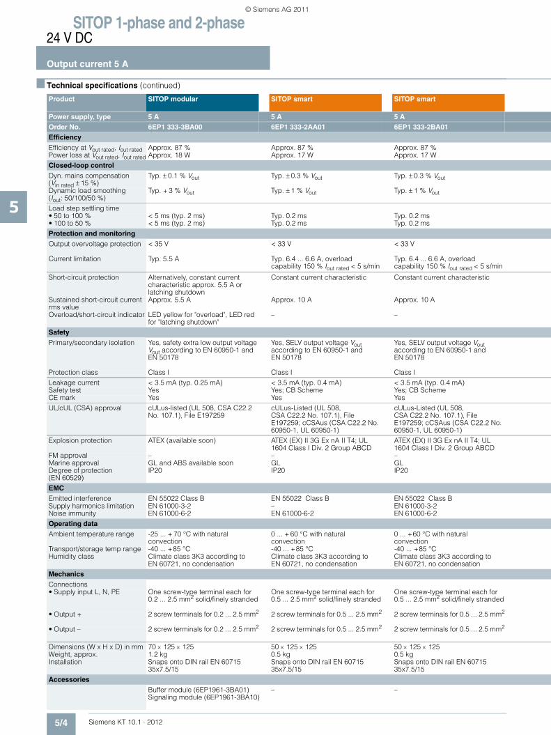
SITOP 1-phase and 2-phase24 V DC
Output current 5 A
5/4 Siemens KT 10.1 · 2012
5
■ Technical specifications (continued)
Product SITOP modular SITOP smart SITOP smart
Power supply, type 5 A 5 A 5 A Order No. 6EP1 333-3BA00 6EP1 333-2AA01 6EP1 333-2BA01Efficiency Efficiency at Vout rated, Iout rated Approx. 87 % Approx. 87 % Approx. 87 %Power loss at Vout rated, Iout rated Approx. 18 W Approx. 17 W Approx. 17 WClosed-loop control Dyn. mains compensation (Vin rated ± 15 %)
Typ. ± 0.1 % Vout Typ. ± 0.3 % Vout Typ. ± 0.3 % Vout
Dynamic load smoothing(Iout: 50/100/50 %)
Typ. + 3 % Vout Typ. ± 1 % Vout Typ. ± 1 % Vout
Load step settling time• 50 to 100 % < 5 ms (typ. 2 ms) Typ. 0.2 ms Typ. 0.2 ms• 100 to 50 % < 5 ms (typ. 2 ms) Typ. 0.2 ms Typ. 0.2 msProtection and monitoring Output overvoltage protection < 35 V < 33 V < 33 V
Current limitation Typ. 5.5 A Typ. 6.4 ... 6.6 A, overload capability 150 % Iout rated < 5 s/min
Typ. 6.4 ... 6.6 A, overloadcapability 150 % Iout rated < 5 s/min
Short-circuit protection Alternatively, constant current characteristic approx. 5.5 A or latching shutdown
Constant current characteristic Constant current characteristic
Sustained short-circuit current rms value
Approx. 5.5 A Approx. 10 A Approx. 10 A
Overload/short-circuit indicator LED yellow for "overload", LED red for "latching shutdown"
– –
Safety Primary/secondary isolation Yes, safety extra low output voltage
Vout according to EN 60950-1 and EN 50178
Yes, SELV output voltage Vout according to EN 60950-1 and EN 50178
Yes, SELV output voltage Vout according to EN 60950-1 and EN 50178
Protection class Class I Class I Class ILeakage current < 3.5 mA (typ. 0.25 mA) < 3.5 mA (typ. 0.4 mA) < 3.5 mA (typ. 0.4 mA)Safety test Yes Yes; CB Scheme Yes; CB SchemeCE mark Yes Yes YesUL/cUL (CSA) approval cULus-listed (UL 508, CSA C22.2
No. 107.1), File E197259cULus-Listed (UL 508,CSA C22.2 No. 107.1), File E197259; cCSAus (CSA C22.2 No. 60950-1, UL 60950-1)
cULus-Listed (UL 508,CSA C22.2 No. 107.1), File E197259; cCSAus (CSA C22.2 No. 60950-1, UL 60950-1)
Explosion protection ATEX (available soon) ATEX (EX) II 3G Ex nA II T4; UL 1604 Class I Div. 2 Group ABCD
ATEX (EX) II 3G Ex nA II T4; UL 1604 Class I Div. 2 Group ABCD
FM approval – – –Marine approval GL and ABS available soon GL GL Degree of protection (EN 60529)
IP20 IP20 IP20
EMC Emitted interference EN 55022 Class B EN 55022 Class B EN 55022 Class BSupply harmonics limitation EN 61000-3-2 – EN 61000-3-2Noise immunity EN 61000-6-2 EN 61000-6-2 EN 61000-6-2 Operating data Ambient temperature range -25 ... + 70 °C with natural
convection0 ... + 60 °C with natural convection
0 ... +60 °C with natural convection
Transport/storage temp range -40 ... +85 °C -40 ... +85 °C -40 ... +85 °CHumidity class Climate class 3K3 according to
EN 60721, no condensationClimate class 3K3 according to EN 60721, no condensation
Climate class 3K3 according to EN 60721, no condensation
Mechanics Connections • Supply input L, N, PE One screw-type terminal each for
0.2 ... 2.5 mm2 solid/finely strandedOne screw-type terminal each for 0.5 ... 2.5 mm2 solid/finely stranded
One screw-type terminal each for 0.5 ... 2.5 mm2 solid/finely stranded
• Output + 2 screw terminals for 0.2 ... 2.5 mm2 2 screw terminals for 0.5 ... 2.5 mm2 2 screw terminals for 0.5 ... 2.5 mm2
• Output – 2 screw terminals for 0.2 ... 2.5 mm2 2 screw terminals for 0.5 ... 2.5 mm2 2 screw terminals for 0.5 ... 2.5 mm2
Dimensions (W x H x D) in mm 70 × 125 × 125 50 × 125 × 125 50 × 125 × 125Weight, approx. 1.2 kg 0.5 kg 0.5 kgInstallation Snaps onto DIN rail EN 60715
35x7.5/15Snaps onto DIN rail EN 60715 35x7.5/15
Snaps onto DIN rail EN 60715 35x7.5/15
AccessoriesBuffer module (6EP1961-3BA01) Signaling module (6EP1961-3BA10)
– –
KT10_EN_gesamt.book Seite 4 Mittwoch, 12. Oktober 2011 11:00 11
© Siemens AG 2011

SITOP 1-phase and 2-phase24 V DC
Output current 5 A
5/5Siemens KT 10.1 · 2012
5
SITOP in SIMATIC designThe S7-300 version
SITOP lite PSU100L
SITOP in SIMATIC designThe outdoor version
Special designThe flat design
5 A 5 A 5 A 5 A 6ES7 307-1EA01-0AA0 6EP1 333-1LB00 6ES7 307-1EA80-0AA0 2) 6EP1 333-1AL12
Approx. 87 % Approx. 86 % Approx. 84 % Approx. 88 %Approx. 18 W Approx. 17 W Approx. 23 W Approx. 17 W
Typ. ± 0.1 % Vout Typ. ± 0.3 % Vout Typ. ± 0.3 % Vout Typ. ± 0.3 % Vout
Typ. ± 1 % Vout Typ. ± 2 % Vout (Iout: 10/90/10 %) Typ. ± 3 % Vout Typ. ± 0.5 % Vout
Typ. 0.3 ms Typ. 0.4 ms (10 to 90 %) < 5 ms (typ. 0.2 ms) < 5 ms (typ. 0.1 ms)Typ. 0.3 ms Typ. 0.4 ms (90 to 10 %) < 5 ms (typ. 0.2 ms) < 5 ms (typ. 0.1 ms)
Additional control loop, shutdown at < 28.8 V, automatic restart
< 33 V Additional control loop, shutdown at approx. 30 V, automatic restart
Additional control loop, shutdown at approx. 33 V, automatic restart
5.5 ... 6.5 A Typically 5.25 A 5.5 ... 6.5 A 5.5 ... 6.5 A
Electronic shutdown, automatic restart
Constant current characteristic Electronic shutdown, automatic restart
Electronic shutdown, automatic restart
< 7 A Approx. 8 A < 5 A < 5 A
– – – –
Yes, SELV output voltage Vout according to EN 60950-1 and EN 50178
Yes, SELV output voltage Vout according to EN 60950-1 and EN 50178
Yes, SELV output voltage Vout according to EN 60950-1 and EN 50178, creepage distances and clearances > 8 mm
Yes, SELV output voltage Vout according to EN 60950-1 and EN 50178
Class I Class I Class I Class I< 3.5 mA (typ. 0.5 mA) < 3.5 mA (typ. 0.4 mA) < 3.5 mA (typ. 0.3 mA) < 3.5 mA (typ. 0.26 mA)Notified Body Yes; CB Scheme in preparation Yes YesYes Yes Yes YescULus-listed (UL 508, CSA C22.2 No. 142) File E143289
cULus-Listed (UL 508,CSA C22.2 No. 107.1) in preparation
UL-listed (UL 508), file E143289, CSA (CSA 22.2 No. 142)
cULus-listed (UL 508, CSA C22.2 No. 107.1), File E197259
ATEX (EX) II 3G Ex nA II T4; UL 1604 Class I Div. 2 Group ABCD
– – –
Class I Div. 2 Group ABCD, T 4 – – –In S7-300 system – – –IP20 IP20 IP20 IP20
EN 55022 Class B EN 55022 Class A EN 55011 Class A EN 55022 Class BEN 61000-3-2 – – –EN 61000-6-2 EN 61000-6-2 EN 61000-6-2 EN 61000-6-2
0 ... +60 °C with natural convection
0 ... +60 °C with natural convection
-25 ... + 70 °C with natural convection
0 ... + 60 °C with natural convection
-40 ... + 85 °C -40 ... + 85 °C -40 ... + 85 °C -40 ... + 85 °CClimate class 3K3 according to EN 60721, no condensation
Climate class 3K3 according to EN 60721, no condensation
Climate class 3K5 acc to EN 60721, with transient condensation
Climate class 3K3 according to EN 60721, no condensation
One screw-type terminal each for 0.5 ... 2.5 mm2 solid/finely stranded
One screw-type terminal each for 0.5 ... 2.5 mm2 solid/finely stranded
One screw-type terminal each for 0.5 ... 2.5 mm2 solid/finely stranded
One screw-type terminal each for 0.5 ... 2.5 mm2 solid/finely stranded
3 screw terminals for 0.5 ... 2.5 mm2
2 screw terminals for 0.5 ... 2.5 mm2
3 screw terminals for 0.5 ... 2.5 mm2
3 screw terminals for 0.5 ... 2.5 mm2
3 screw terminals for 0.5 ... 2.5 mm2
2 screw terminals for 0.5 ... 2.5 mm2
3 screw terminals for 0.5 ... 2.5 mm2
3 screw terminals for 0.5 ... 2.5 mm2
60 × 125 × 120 50 × 125 × 125 80 × 125 × 120 160 × 130 × 600.6 kg 0.5 kg 0.57 kg 0.6 kgCan be mounted onto S7 rail Snaps onto DIN rail EN 60715
35x7.5/15Can be mounted onto S7 rail Snaps onto DIN rail EN 60715
35x7.5/15
Mounting adapter for standard mounting rail (6EP1 971-1BA00)
– Mounting adapter for standard mounting rail (6ES7390-6BA00-0AA0)
–
KT10_EN_gesamt.book Seite 5 Mittwoch, 12. Oktober 2011 11:00 11
© Siemens AG 2011
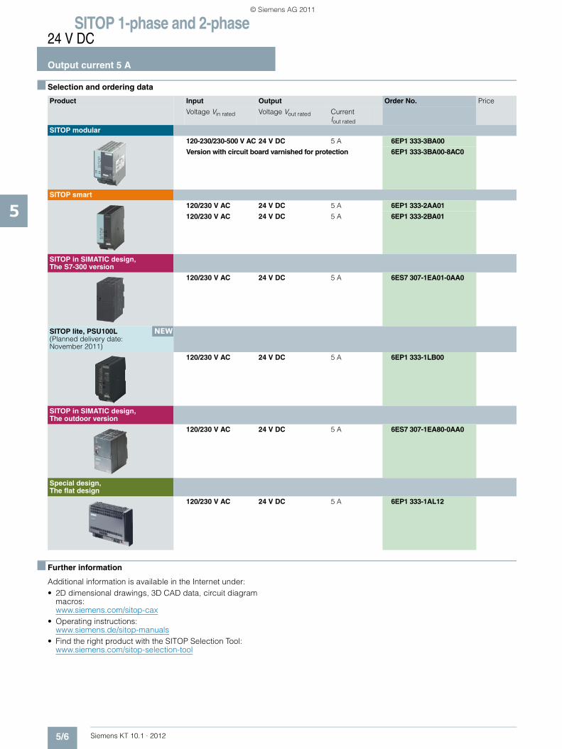
SITOP 1-phase and 2-phase24 V DC
Output current 5 A
5/6 Siemens KT 10.1 · 2012
5
■ Selection and ordering data
■ Further information
Additional information is available in the Internet under:• 2D dimensional drawings, 3D CAD data, circuit diagram
macros: www.siemens.com/sitop-cax
• Operating instructions:www.siemens.de/sitop-manuals
• Find the right product with the SITOP Selection Tool: www.siemens.com/sitop-selection-tool
Product Input Output Order No. Price
Voltage Vin rated Voltage Vout rated Current Iout rated
SITOP modular
120-230/230-500 V AC 24 V DC 5 A 6EP1 333-3BA00
Version with circuit board varnished for protection 6EP1 333-3BA00-8AC0
SITOP smart
120/230 V AC 24 V DC 5 A 6EP1 333-2AA01
120/230 V AC 24 V DC 5 A 6EP1 333-2BA01
SITOP in SIMATIC design, The S7-300 version
120/230 V AC 24 V DC 5 A 6ES7 307-1EA01-0AA0
SITOP lite, PSU100L (Planned delivery date: November 2011)
120/230 V AC 24 V DC 5 A 6EP1 333-1LB00
SITOP in SIMATIC design, The outdoor version
120/230 V AC 24 V DC 5 A 6ES7 307-1EA80-0AA0
Special design, The flat design
120/230 V AC 24 V DC 5 A 6EP1 333-1AL12
NEW
KT10_EN_gesamt.book Seite 6 Mittwoch, 12. Oktober 2011 11:00 11
© Siemens AG 2011

Siemens KT 10.1 · 2012
66/2 SITOP PSA100E 6 A6/2 PSU100D 6.2 A6/4 Ordering data and additional information
SITOP 1-phase and 2-phase24 V DC, 6 A
Export regulations AL and ECCNsee page 17/9
KT10_EN_gesamt.book Seite 1 Mittwoch, 12. Oktober 2011 11:00 11
© Siemens AG 2011
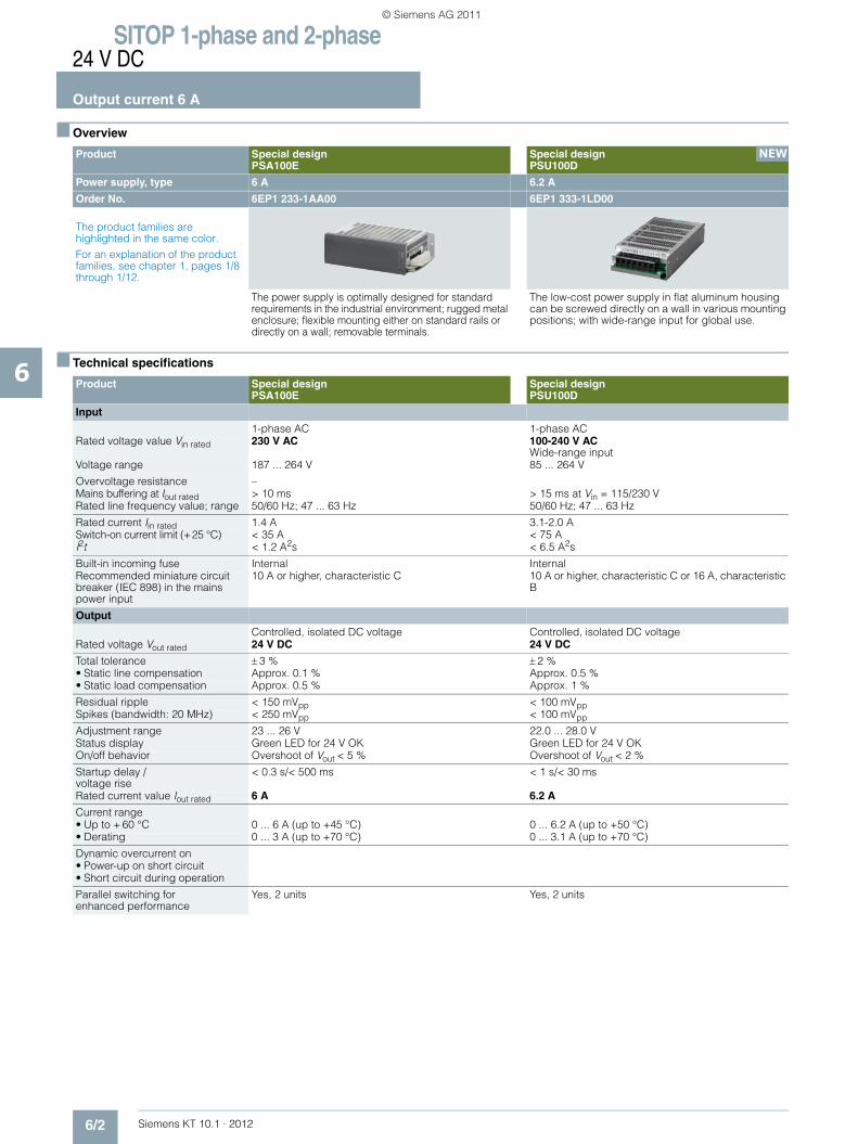
SITOP 1-phase and 2-phase24 V DC
Output current 6 A
6/2 Siemens KT 10.1 · 2012
6
■ Overview
■ Technical specifications
Product Special designPSA100E
Special designPSU100D
Power supply, type 6 A 6.2 A
Order No. 6EP1 233-1AA00 6EP1 333-1LD00
The product families are highlighted in the same color.For an explanation of the product families, see chapter 1, pages 1/8 through 1/12.
The power supply is optimally designed for standard requirements in the industrial environment; rugged metal enclosure; flexible mounting either on standard rails or directly on a wall; removable terminals.
The low-cost power supply in flat aluminum housing can be screwed directly on a wall in various mounting positions; with wide-range input for global use.
Product Special designPSA100E
Special designPSU100D
Input
1-phase AC 1-phase ACRated voltage value Vin rated 230 V AC 100-240 V AC
Wide-range inputVoltage range 187 ... 264 V 85 ... 264 V
Overvoltage resistance –Mains buffering at Iout rated > 10 ms > 15 ms at Vin = 115/230 V Rated line frequency value; range 50/60 Hz; 47 ... 63 Hz 50/60 Hz; 47 ... 63 Hz
Rated current Iin rated 1.4 A 3.1-2.0 ASwitch-on current limit (+25 °C) < 35 A < 75 AI2t < 1.2 A2s < 6.5 A2s
Built-in incoming fuse Internal InternalRecommended miniature circuit breaker (IEC 898) in the mains power input
10 A or higher, characteristic C 10 A or higher, characteristic C or 16 A, characteristic B
Output
Controlled, isolated DC voltage Controlled, isolated DC voltageRated voltage Vout rated 24 V DC 24 V DC
Total tolerance ± 3 % ± 2 %• Static line compensation Approx. 0.1 % Approx. 0.5 %• Static load compensation Approx. 0.5 % Approx. 1 %
Residual ripple < 150 mVpp < 100 mVppSpikes (bandwidth: 20 MHz) < 250 mVpp < 100 mVpp
Adjustment range 23 ... 26 V 22.0 ... 28.0 V Status display Green LED for 24 V OK Green LED for 24 V OKOn/off behavior Overshoot of Vout < 5 % Overshoot of Vout < 2 %
Startup delay /voltage rise
< 0.3 s/< 500 ms < 1 s/< 30 ms
Rated current value Iout rated 6 A 6.2 A
Current range • Up to + 60 °C 0 ... 6 A (up to +45 °C) 0 ... 6.2 A (up to +50 °C)• Derating 0 ... 3 A (up to +70 °C) 0 ... 3.1 A (up to +70 °C)
Dynamic overcurrent on • Power-up on short circuit• Short circuit during operation
Parallel switching for enhanced performance
Yes, 2 units Yes, 2 units
NEW
KT10_EN_gesamt.book Seite 2 Mittwoch, 12. Oktober 2011 11:00 11
© Siemens AG 2011

SITOP 1-phase and 2-phase24 V DC
Output current 6 A
6/3Siemens KT 10.1 · 2012
6
■ Technical specifications (continued)
Product Special designPSA100E
Special designPSU100D
Power supply, type 6 A 6.2 AOrder No. 6EP1 233-1AA00 6EP1 333-1LD00Efficiency Efficiency at Vout rated, Iout rated Approx. 87 % Approx. 86 %Power loss at Vout rated, Iout rated Approx. 22 W Approx. 24 WClosed-loop control Dyn. mains compensation (Vin rated ± 15 %)
<0.3 % Vout Typ. ± 0.5 % Vout
Dynamic load smoothing(Iout: 50/100/50 %)
Typ. ± 2.0 % Vout Typ. ± 5.0 % Vout (0 to 100 %)
Load step settling time• 50 at 100 % Typ. 0.1 ms• 100 at 50 % Typ. 0.1 msProtection and monitoring Output overvoltage protection < 35 V < 35 VCurrent limitation Typ. 6.6 A 7.4 A
Short-circuit protection Electronic shutdown, automatic restart
Electronic shutdown, automatic restart
Sustained short-circuit current rms value
< 3.6 A 16 A
Overload/short-circuit indicator – –Safety Primary/secondary isolation Yes, SELV output voltage Vout according to
EN 60950-1 and EN 50178Yes, safety extra low output voltage Vout according to EN 60950-1
Protection class Class I Class ILeakage current < 3.5 mA (typ. 0.8 mA) < 3.5 mA (typ. 1 mA)Safety test Yes; CB Scheme Yes; CB Scheme in preparationCE mark Yes YesUL/cUL (CSA) approval cULus-Listed (UL 508, CSA C22.2 No.107.1), File
E197259cULus-Listed (UL 508, CSA C22.2 No.107.1) in preparation; cURus (UL 60950-1, CSA C22.2 No. 60950-1) in preparation
Explosion protection – –FM approval – –Marine approval – –Degree of protection (EN 60529) IP20 IP20EMC Emitted interference EN 55022 Class B EN 55022 Class BSupply harmonics limitation – –Noise immunity EN 61000-6-2 EN 61000-6-2Operating data Ambient temperature range -10 ... +70 °C with natural convection -10 ... +70 °C with natural convection
Transport/storage temperature range
-40 ... +85 °C -25 ... +85 °C
Humidity class Climate class 3K3 according to EN 60721, no condensation
Mechanics Connections • Supply input L, N, PE Removable screw terminal for
1 × 0.5 ... 2.5 mm2 eachOne screw-type terminal each for 0.3 ... 1.3 mm2
solid/finely stranded• Output + Removable screw terminal for 1 × 0.5 ... 2.5 mm2 2 screw terminals for 0.3 ... 1.3 mm2
• Output – Removable screw terminal for 1 × 0.5 ... 2.5 mm2 2 screw terminals for 0.3 ... 1.3 mm2
Dimensions (W x H x D) in mm 52 × 170 × 110 97 x 178 x 38Weight, approx. 0.9 kg 0.55 kgInstallation Snaps onto DIN rail EN 60715 35x7.5/15.
Wall mounting Wall mounting
Accessories– –
KT10_EN_gesamt.book Seite 3 Mittwoch, 12. Oktober 2011 11:00 11
© Siemens AG 2011

SITOP 1-phase and 2-phase24 V DC
Output current 6 A
6/4 Siemens KT 10.1 · 2012
6
■ Selection and ordering data
■ Further information
Additional information is available in the Internet under:• 2D dimensional drawings, 3D CAD data, circuit diagram
macros: www.siemens.com/sitop-cax
• Operating instructions:www.siemens.de/sitop-manuals
• Find the right product with the SITOP Selection Tool: www.siemens.com/sitop-selection-tool
Product Input Output Order No. Price
Voltage Vin rated Voltage Vout rated Current Iout rated
Special design, PSA100E
230 V AC 24 V DC 6 A 6EP1 233-1AA00
Special design, PSU100D (Planned delivery date: December 2011)
100-240 V AC 24 V DC 6.2 A 6EP1 333-1LD00
NEW
KT10_EN_gesamt.book Seite 4 Mittwoch, 12. Oktober 2011 11:00 11
© Siemens AG 2011

Siemens KT 10.1 · 2012
77/2 SITOP modular 10 A7/2 SITOP smart 10 A7/3 The S7-300 version 10 A7/3 SITOP PSU100L 10 A7/3 The flat design 10 A7/6 Ordering data and additional information
SITOP 1-phase and 2-phase24 V DC, 10 A
Export regulations AL and ECCNsee page 17/9
KT10_EN_gesamt.book Seite 1 Mittwoch, 12. Oktober 2011 11:00 11
© Siemens AG 2011
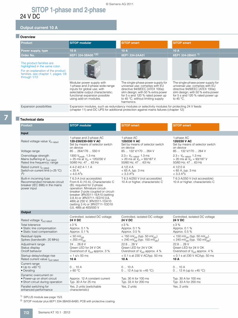
SITOP 1-phase and 2-phase24 V DC
Output current 10 A
7/2 Siemens KT 10.1 · 2012
7
■ Overview
■ Technical data
1) SIPLUS module see page 15/3.2) SITOP modular plus 6EP1 334-3BA00-8AB0, PCB with protective coating.
Product SITOP modular SITOP smart SITOP smart
Power supply, type 10 A 10 A 10 A
Order No. 6EP1 334-3BA00 1)2) 6EP1 334-2AA01 6EP1 334-2BA01 1)
The product families are highlighted in the same color.For an explanation of the product families, see chapter 1, pages 1/8 through 1/12.
Modular power supply with 1-phase and 2-phase wide-range inputs for global use; with selectable output characteristic; functional expansion possible using add-on modules.
The single-phase power supply for universal use; complies with EU directive 94/9/EEC (ATEX 100a); slim design; with 50 % extra power for 5 s and 120 % rated power up to 45 °C; without limiting supply harmonics.
The single-phase power supply for universal use; complies with EU directive 94/9/EEC (ATEX 100a); slim design; with 50 % extra power for 5 s and 120 % rated power up to 45 °C.
Expansion possibilities Expansion modules, such as redundancy modules or selectivity modules for protecting 24 V feeds(chapter 11) and DC UPS for additional protection against mains failures (chapter 12)
Product SITOP modular SITOP smart SITOP smart
Input
1-phase and 2-phase AC 1-phase AC 1-phase ACRated voltage value Vin rated 120-230/230-500 V AC
Set by means of selector switch on device
120/230 V ACSet by means of selector switchon device
120/230 V ACSet by means of selector switchon device
Voltage range 85 ... 264/176 ... 550 V 85 ... 132 V/170 ... 264 V 85 ... 132 V/170 ... 264 V
Overvoltage strength 1300 Vpeak, 1.3 ms 2.3 × Vin rated, 1.3 ms 2.3 × Vin rated, 1.3 ms Mains buffering at Iout rated > 25 ms at Vin = 120/230 V > 20 ms at Vin = 93/187 V > 20 ms at Vin = 93/187 V Rated line frequency; range 50/60 Hz; 47 ... 63 Hz 50/60 Hz; 47 ... 63 Hz 50/60 Hz; 47 ... 63 Hz
Rated current Iin rated 4.4-2.4/2.4-1.1 A 4.1/2.4 A 4.1/2.0 ASwitch-on current limit (+25 °C) < 35 A < 65 A, typ. 3 ms < 65 A, typ. 3 msI2t < 4.0 A2s < 3.3 A2s < 3.3 A2s
Built-in incoming fuse T 6.3 A (not accessible) T 6.3 A/250 V (not accessible) T 6.3 A/250 V (not accessible)Recommended miniature circuit breaker (IEC 898) in the mains power input
From 6 A (10 A), Characteristic C (B); required for 2-phase operation: Miniature circuit-breaker 2-pole coupled or circuit-breaker 3RV2011-1EA10 (setting 3.8 A) or 3RV2711-1ED10 (UL 489) at 230 V; 3RV2011-1DA10 (setting 3 A) or 3RV2711-1DD10 (UL 489) at 400/500 V
10 A or higher, characteristic C 10 A or higher, characteristic C
Output
Controlled, isolated DC voltage Controlled, isolated DC voltage Controlled, isolated DC voltageRated voltage Vout rated 24 V DC 24 V DC 24 V DC
Total tolerance ± 3 % ± 3 % ± 3 %• Static line compensation Approx. 0.1 % Approx. 0.1 % Approx. 0.1 %• Static load compensation Approx. 0.1 % Approx. 0.5 % Approx. 0.5 %
Residual ripple < 50 mVpp < 150 mVpp (typ. 50 mVpp) < 150 mVpp (typ. 50 mVpp)Spikes (bandwidth: 20 MHz) < 200 mVpp < 240 mVpp (typ. 150 mVpp) < 240 mVpp (typ. 150 mVpp)
Adjustment range 24 ... 28.8 V 22.8 ... 28 V 22.8 ... 28 VStatus display Green LED for 24 V OK Green LED for 24 V OK Green LED for 24 V OKOn/off behavior Overshoot of Vout approx. 3 % Overshoot of Vout approx. 4 % Overshoot of Vout approx. 4 %
Startup delay/voltage rise < 1 s/< 50 ms < 0.1 s at 230 V AC/typ. 50 ms < 0.1 s at 230 V AC/typ. 50 msRated current value Iout rated 10 A 10 A 10 A
Current range • Up to +60 °C 0 ... 10 A 0 ... 10 A 0 ... 10 A • Derating > 60 °C 0 ... 12 A (up to +45 °C) 0 ... 12 A (up to +45 °C)
Dynamic overcurrent on • Power-up on short circuit Approx. 12 A constant current Typ. 30 A for 100 ms Typ. 30 A for 100 ms• Short circuit during operation Typ. 30 A for 25 ms Typ. 33 A for 200 ms Typ. 33 A for 200 ms
Parallel switching for enhanced performance
Yes, 2 units (switchable characteristic)
Yes, 2 units Yes, 2 units
KT10_EN_gesamt.book Seite 2 Mittwoch, 12. Oktober 2011 11:00 11
© Siemens AG 2011

SITOP 1-phase and 2-phase24 V DC
Output current 10 A
7/3Siemens KT 10.1 · 2012
71)
1) SIPLUS module see page 15/3.
SITOP in SIMATIC designThe S7-300 version
SITOP lite PSU100L
Special designThe flat design
10 A 10 A 10 A
6ES7 307-1KA02-0AA0 1) 6EP1 334-1LB00 6EP1 334-1AL12
The proven power supply in SIMATIC S7-300 design; with PS-CPU connecting comb and for mounting direct on S7 rail.
The low-cost power supply for standard requirements in industrial environments; slim design; wide-range input with manual switchover.
The flat design is of great advantage where only low mounting depths are available, e.g. for use with distributed I/O, in machine benches or alcoves; design matched to SIMATIC ET 200B.
Expansion modules, such as redundancy modules or selectivity modules for protecting 24 V feeds(chapter 11) and DC UPS for additional protection against mains failures (chapter 12)
NEW
SITOP in SIMATIC designThe S7-300 version
SITOP lite PSU100L
Special designThe flat design
1-phase AC 1-phase AC 1-phase AC120/230 V ACAutomatic range switch-over
120/230 V ACSet by means of selector switchon device
120/230 V AC Set by means of selector switchon device
85 ... 132 V/170 ... 264 V 85 ... 132 V/170 ... 264 V 85 ... 132 V/170 ... 264 V
2.3 × Vin rated, 1.3 ms 2.3 × Vin rated, 1.3 ms 2.3 × Vin rated, 1.3 ms> 20 ms at Vin = 93/187 V > 20 ms at Vin = 93/187 V > 20 ms at Vin = 93/187 V 50/60 Hz; 47 ... 63 Hz 50/60 Hz; 47 ... 63 Hz 50/60 Hz; 47 ... 63 Hz
4.2/1.9 A 4.1/2.4 A 4.0/2.5 A< 55 A, < 3 ms < 65 A, typ. 3 ms < 65 A, < 3 ms< 3.3 A2s < 3.3 A2s < 3.3 A2s
T 6.3 A/250 V (not accessible) T 6.3 A/250 V (not accessible) T 6.3 A/250 V (not accessible)10 A or higher, characteristic C 10 A or higher, characteristic C 10 A or higher, characteristic C
Controlled, isolated DC voltage Controlled, isolated DC voltage Controlled, isolated DC voltage24 V DC 24 V DC 24 V DC
± 3 % ± 3 % ± 1 %Approx. 0.1 % Approx. 0.1 % Approx. 0.1 %Approx. 0.5 % Approx. 0.5 % Approx. 0.5 %
< 50 mVpp (typ. 15 mVpp) < 150 mVpp (typ. 50 mVpp) < 150 mVpp (typ. 50 mVpp)< 150 mVpp (typ. 60 mVpp) < 240 mVpp (typ. 150 mVpp) < 240 mVpp (typ. 200 mVpp)
– 22.8 ... 26.4 V 22 ... 29 VGreen LED for 24 V OK Green LED for 24 V OK Green LED for 24 V OKNo overshoot of Vout (soft start) Overshoot of Vout approx. 4 % No overshoot of Vout (soft start)
< 2 s/typ. 10 ms < 1.5 s/typ. 170 ms < 2 s/typ. 40 ms10 A 10 A 10 A
0 ... 10 A 0 ... 7 A 0 ... 10 A – 0 ... 10 A (up to +45 °C) –
Typ. 38 A for 80 ms – Typ. 35 A for 700 msTyp. 38 A for 80 ms – Typ. 35 A for 700 ms
Yes Yes, 2 units Yes, 2 units
KT10_EN_gesamt.book Seite 3 Mittwoch, 12. Oktober 2011 11:00 11
© Siemens AG 2011
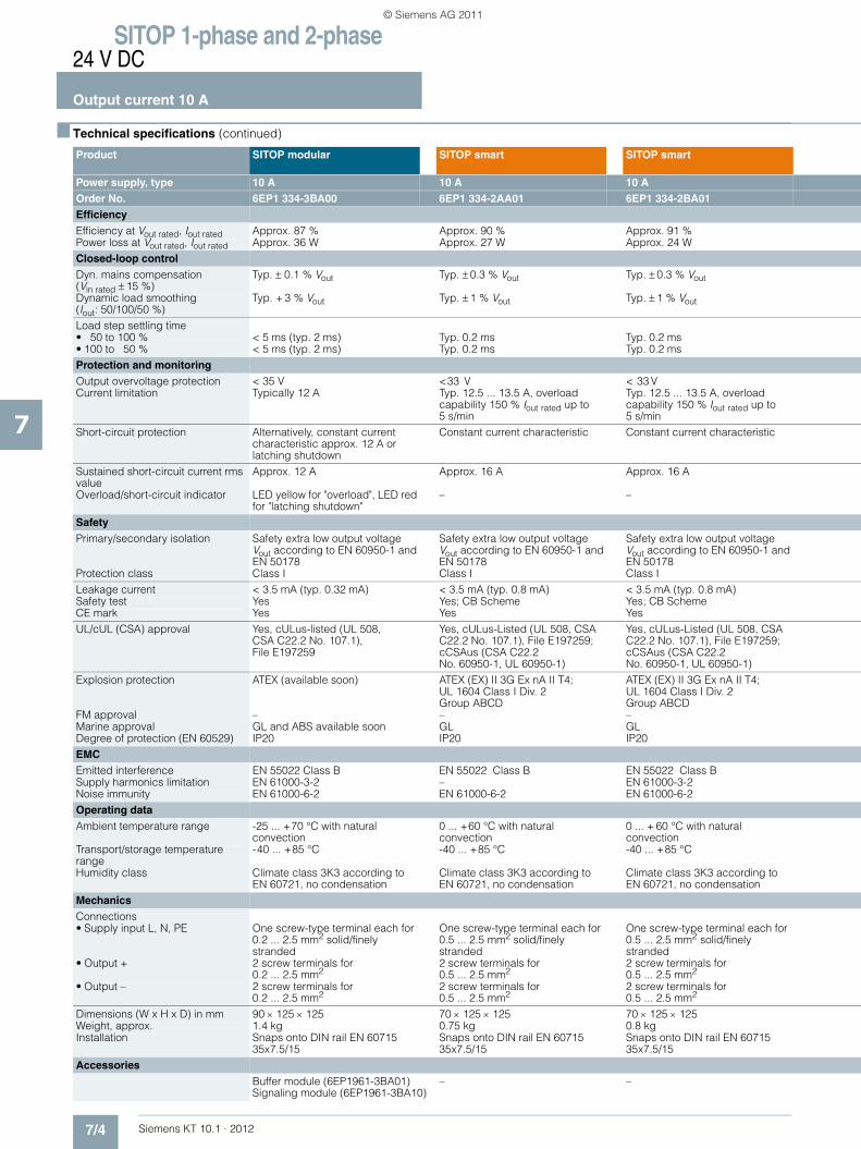
SITOP 1-phase and 2-phase24 V DC
Output current 10 A
7/4 Siemens KT 10.1 · 2012
7
■ Technical specifications (continued).
Product SITOP modular SITOP smart SITOP smart
Power supply, type 10 A 10 A 10 A Order No. 6EP1 334-3BA00 6EP1 334-2AA01 6EP1 334-2BA01Efficiency Efficiency at Vout rated, Iout rated Approx. 87 % Approx. 90 % Approx. 91 %Power loss at Vout rated, Iout rated Approx. 36 W Approx. 27 W Approx. 24 WClosed-loop control Dyn. mains compensation (Vin rated ± 15 %)
Typ. ± 0.1 % Vout Typ. ± 0.3 % Vout Typ. ± 0.3 % Vout
Dynamic load smoothing(Iout: 50/100/50 %)
Typ. + 3 % Vout Typ. ± 1 % Vout Typ. ± 1 % Vout
Load step settling time• 50 to 100 % < 5 ms (typ. 2 ms) Typ. 0.2 ms Typ. 0.2 ms• 100 to 50 % < 5 ms (typ. 2 ms) Typ. 0.2 ms Typ. 0.2 msProtection and monitoring Output overvoltage protection < 35 V <33 V < 33 VCurrent limitation Typically 12 A Typ. 12.5 ... 13.5 A, overload
capability 150 % Iout rated up to 5 s/min
Typ. 12.5 ... 13.5 A, overload capability 150 % Iout rated up to 5 s/min
Short-circuit protection Alternatively, constant current characteristic approx. 12 A or latching shutdown
Constant current characteristic Constant current characteristic
Sustained short-circuit current rms value
Approx. 12 A Approx. 16 A Approx. 16 A
Overload/short-circuit indicator LED yellow for "overload", LED red for "latching shutdown"
– –
Safety Primary/secondary isolation Safety extra low output voltage
Vout according to EN 60950-1 and EN 50178
Safety extra low output voltage Vout according to EN 60950-1 and EN 50178
Safety extra low output voltage Vout according to EN 60950-1 and EN 50178
Protection class Class I Class I Class ILeakage current < 3.5 mA (typ. 0.32 mA) < 3.5 mA (typ. 0.8 mA) < 3.5 mA (typ. 0.8 mA)Safety test Yes Yes; CB Scheme Yes; CB SchemeCE mark Yes Yes YesUL/cUL (CSA) approval Yes, cULus-listed (UL 508,
CSA C22.2 No. 107.1),File E197259
Yes, cULus-Listed (UL 508, CSA C22.2 No. 107.1), File E197259; cCSAus (CSA C22.2 No. 60950-1, UL 60950-1)
Yes, cULus-Listed (UL 508, CSA C22.2 No. 107.1), File E197259; cCSAus (CSA C22.2 No. 60950-1, UL 60950-1)
Explosion protection ATEX (available soon) ATEX (EX) II 3G Ex nA II T4; UL 1604 Class I Div. 2 Group ABCD
ATEX (EX) II 3G Ex nA II T4; UL 1604 Class I Div. 2 Group ABCD
FM approval – – –Marine approval GL and ABS available soon GL GLDegree of protection (EN 60529) IP20 IP20 IP20EMC Emitted interference EN 55022 Class B EN 55022 Class B EN 55022 Class BSupply harmonics limitation EN 61000-3-2 – EN 61000-3-2Noise immunity EN 61000-6-2 EN 61000-6-2 EN 61000-6-2Operating data Ambient temperature range -25 ... +70 °C with natural
convection0 ... +60 °C with natural convection
0 ... + 60 °C with natural convection
Transport/storage temperature range
-40 ... +85 °C -40 ... +85 °C -40 ... +85 °C
Humidity class Climate class 3K3 according to EN 60721, no condensation
Climate class 3K3 according to EN 60721, no condensation
Climate class 3K3 according to EN 60721, no condensation
Mechanics Connections • Supply input L, N, PE One screw-type terminal each for
0.2 ... 2.5 mm2 solid/finely stranded
One screw-type terminal each for 0.5 ... 2.5 mm2 solid/finely stranded
One screw-type terminal each for 0.5 ... 2.5 mm2 solid/finely stranded
• Output + 2 screw terminals for 0.2 ... 2.5 mm2
2 screw terminals for 0.5 ... 2.5 mm2
2 screw terminals for 0.5 ... 2.5 mm2
• Output – 2 screw terminals for 0.2 ... 2.5 mm2
2 screw terminals for 0.5 ... 2.5 mm2
2 screw terminals for 0.5 ... 2.5 mm2
Dimensions (W x H x D) in mm 90 × 125 × 125 70 × 125 × 125 70 × 125 × 125Weight, approx. 1.4 kg 0.75 kg 0.8 kgInstallation Snaps onto DIN rail EN 60715
35x7.5/15Snaps onto DIN rail EN 60715 35x7.5/15
Snaps onto DIN rail EN 60715 35x7.5/15
Accessories Buffer module (6EP1961-3BA01) Signaling module (6EP1961-3BA10)
– –
KT10_EN_gesamt.book Seite 4 Mittwoch, 12. Oktober 2011 11:00 11
© Siemens AG 2011
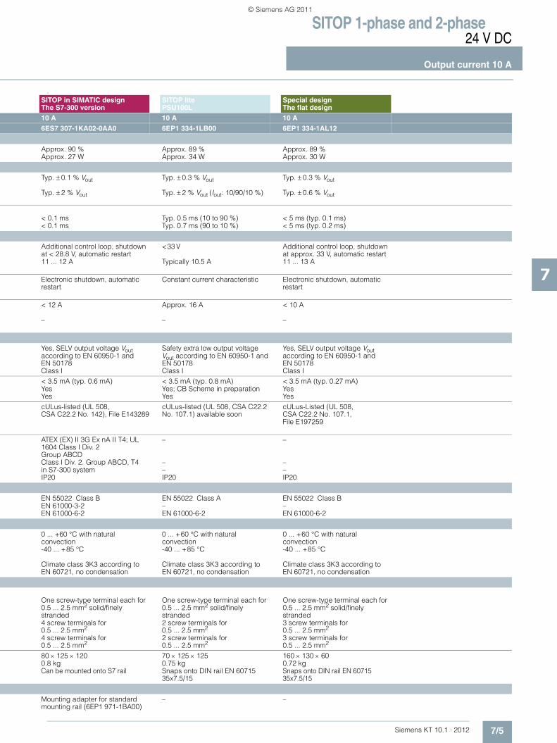
SITOP 1-phase and 2-phase24 V DC
Output current 10 A
7/5Siemens KT 10.1 · 2012
7
1)
SITOP in SIMATIC designThe S7-300 version
SITOP lite PSU100L
Special designThe flat design
10 A 10 A 10 A 6ES7 307-1KA02-0AA0 6EP1 334-1LB00 6EP1 334-1AL12
Approx. 90 % Approx. 89 % Approx. 89 %Approx. 27 W Approx. 34 W Approx. 30 W
Typ. ± 0.1 % Vout Typ. ± 0.3 % Vout Typ. ± 0.3 % Vout
Typ. ± 2 % Vout Typ. ± 2 % Vout (Iout: 10/90/10 %) Typ. ± 0.6 % Vout
< 0.1 ms Typ. 0.5 ms (10 to 90 %) < 5 ms (typ. 0.1 ms)< 0.1 ms Typ. 0.7 ms (90 to 10 %) < 5 ms (typ. 0.2 ms)
Additional control loop, shutdown at < 28.8 V, automatic restart
<33 V Additional control loop, shutdown at approx. 33 V, automatic restart
11 ... 12 A Typically 10.5 A 11 ... 13 A
Electronic shutdown, automatic restart
Constant current characteristic Electronic shutdown, automatic restart
< 12 A Approx. 16 A < 10 A
– – –
Yes, SELV output voltage Vout according to EN 60950-1 and EN 50178
Safety extra low output voltage Vout according to EN 60950-1 and EN 50178
Yes, SELV output voltage Vout according to EN 60950-1 and EN 50178
Class I Class I Class I< 3.5 mA (typ. 0.6 mA) < 3.5 mA (typ. 0.8 mA) < 3.5 mA (typ. 0.27 mA)Yes Yes; CB Scheme in preparation YesYes Yes YescULus-listed (UL 508, CSA C22.2 No. 142), File E143289
cULus-listed (UL 508, CSA C22.2 No. 107.1) available soon
cULus-Listed (UL 508, CSA C22.2 No. 107.1, File E197259
ATEX (EX) II 3G Ex nA II T4; UL 1604 Class I Div. 2 Group ABCD
– –
Class I Div. 2. Group ABCD, T4 – –in S7-300 system – –IP20 IP20 IP20
EN 55022 Class B EN 55022 Class A EN 55022 Class BEN 61000-3-2 – –EN 61000-6-2 EN 61000-6-2 EN 61000-6-2
0 ... +60 °C with natural convection
0 ... +60 °C with natural convection
0 ... +60 °C with natural convection
-40 ... +85 °C -40 ... +85 °C -40 ... +85 °C
Climate class 3K3 according to EN 60721, no condensation
Climate class 3K3 according to EN 60721, no condensation
Climate class 3K3 according to EN 60721, no condensation
One screw-type terminal each for 0.5 ... 2.5 mm2 solid/finely stranded
One screw-type terminal each for 0.5 ... 2.5 mm2 solid/finely stranded
One screw-type terminal each for 0.5 ... 2.5 mm2 solid/finely stranded
4 screw terminals for 0.5 ... 2.5 mm2
2 screw terminals for 0.5 ... 2.5 mm2
3 screw terminals for 0.5 ... 2.5 mm2
4 screw terminals for 0.5 ... 2.5 mm2
2 screw terminals for 0.5 ... 2.5 mm2
3 screw terminals for 0.5 ... 2.5 mm2
80 × 125 × 120 70 × 125 × 125 160 × 130 × 600.8 kg 0.75 kg 0.72 kgCan be mounted onto S7 rail Snaps onto DIN rail EN 60715
35x7.5/15Snaps onto DIN rail EN 60715 35x7.5/15
Mounting adapter for standard mounting rail (6EP1 971-1BA00)
– –
KT10_EN_gesamt.book Seite 5 Mittwoch, 12. Oktober 2011 11:00 11
© Siemens AG 2011

SITOP 1-phase and 2-phase24 V DC
Output current 10 A
7/6 Siemens KT 10.1 · 2012
7
■ Selection and ordering data
■ Further information
Additional information is available in the Internet under:• 2D dimensional drawings, 3D CAD data, circuit diagram
macros: www.siemens.com/sitop-cax
• Operating instructions:www.siemens.de/sitop-manuals
• Find the right product with the SITOP Selection Tool: www.siemens.com/sitop-selection-tool
Product Input Output Order No. Price
Voltage Vin rated Voltage Vout rated Current Iout rated
SITOP modular
120-230/230-500 V AC 24 V DC 10 A 6EP1 334-3BA00
Version with circuit board varnished for protection 6EP1 334-3BA00-8AB0
SITOP smart
120/230 V AC 24 V DC 10 A 6EP1 334-2AA01
120/230 V AC 24 V DC 10 A 6EP1 334-2BA01
SITOP in SIMATIC design, The S7-300 version
120/230 V AC 24 V DC 10 A 6ES7 307-1KA02-0AA0
SITOP lite, PSU100L (Planned delivery date: November 2011)
120/230 V AC 24 V DC 10 A 6EP1 334-1LB00
Special design, The flat design
120/230 V AC 24 V DC 10 A 6EP1 334-1AL12
NEW
KT10_EN_gesamt.book Seite 6 Mittwoch, 12. Oktober 2011 11:00 11
© Siemens AG 2011
Siemens KT 10.1 · 2012
88/2 SITOP PSA100E 12 A8/2 PSU100D 12.5 A8/2 SITOP PSU100M 20 A8/3 SITOP PSU400M 20 A8/3 SITOP modular 20 A8/3 SITOP modular 40 A8/8 Ordering data and additional information
SITOP 1-phase and 2-phase 24 V DC, 12 to 40 A
Export regulations AL and ECCNsee page 17/9
KT10_EN_gesamt.book Seite 1 Mittwoch, 12. Oktober 2011 11:00 11
© Siemens AG 2011
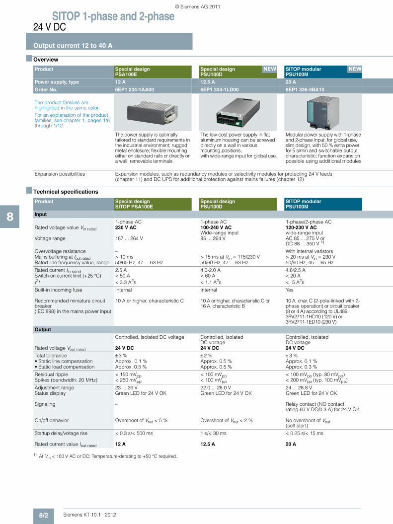
SITOP 1-phase and 2-phase24 V DC
Output current 12 to 40 A
8/2 Siemens KT 10.1 · 2012
8
■ Overview
■ Technical specifications
1) At Vin < 100 V AC or DC: Temperature-derating to +50 °C required.
Product Special designPSA100E
Special design PSU100D
SITOP modular PSU100M
Power supply, type 12 A 12.5 A 20 A
Order No. 6EP1 234-1AA00 6EP1 334-1LD00 6EP1 336-3BA10
The product families are highlighted in the same color.For an explanation of the product families, see chapter 1, pages 1/8 through 1/12.
The power supply is optimally tailored to standard requirements in the industrial environment; rugged metal enclosure; flexible mounting either on standard rails or directly on a wall; removable terminals.
The low-cost power supply in flat aluminum housing can be screwed directly on a wall in various mounting positions; with wide-range input for global use.
Modular power supply with 1-phase and 2-phase input, for global use, slim design, with 50 % extra power for 5 s/min and switchable output characteristic; function expansion possible using additional modules
Expansion possibilities Expansion modules, such as redundancy modules or selectivity modules for protecting 24 V feeds(chapter 11) and DC UPS for additional protection against mains failures (chapter 12)
Product Special designSITOP PSA100E
Special design PSU100D
SITOP modularPSU100M
Input
1-phase AC 1-phase AC 1-phase/2-phase AC Rated voltage value Vin rated 230 V AC 100-240 V AC
Wide-range input120-230 V AC wide-range input
Voltage range 187 ... 264 V 85 ... 264 V AC 85 ... 275 V or DC 88 ... 350 V 1)
Overvoltage resistance – With internal varistorsMains buffering at Iout rated > 10 ms > 15 ms at Vin = 115/230 V > 20 ms at Vin = 230 VRated line frequency value; range 50/60 Hz; 47 ... 63 Hz 50/60 Hz; 47 ... 63 Hz 50/60 Hz; 45 ... 65 Hz
Rated current Iin rated 2.5 A 4.0-2.0 A 4.6/2.5 ASwitch-on current limit (+25 °C) < 50 A < 60 A < 20 AI2t < 3.3 A2s < 1.1 A2s < 5 A2s
Built-in incoming fuse Internal Internal Yes
Recommended miniature circuit breaker (IEC 898) in the mains power input
10 A or higher, characteristic C 10 A or higher, characteristic C or 16 A, characteristic B
10 A, char. C (2-pole-linked with 2-phase operation) or circuit breaker (8 or 4 A) according to UL489: 3RV2711-1HD10 (120 V) or 3RV2711-1ED10 (230 V)
Output
Controlled, isolated DC voltage Controlled, isolatedDC voltage
Controlled, isolatedDC voltage
Rated voltage Vout rated 24 V DC 24 V DC 24 V DC
Total tolerance ± 3 % ± 2 % ± 3 %• Static line compensation Approx. 0.1 % Approx. 0.5 % Approx. 0.1 %• Static load compensation Approx. 0.5 % Approx. 0.5 % Approx. 0.3 %
Residual ripple < 150 mVpp < 100 mVpp < 100 mVpp (typ. 80 mVpp)Spikes (bandwidth: 20 MHz) < 250 mVpp < 100 mVpp < 200 mVpp (typ. 100 mVpp)
Adjustment range 23 ... 26 V 22.0 ... 28.0 V 24 ... 28.8 VStatus display Green LED for 24 V OK Green LED for 24 V OK Green LED for 24 V OK
Signaling – Relay contact (NO contact, rating 60 V DC/0.3 A) for 24 V OK
On/off behavior Overshoot of Vout < 5 % Overshoot of Vout < 2 % No overshoot of Vout (soft start)
Startup delay/voltage rise < 0.3 s/< 500 ms 1 s/< 30 ms < 0.25 s/< 15 ms
Rated current value Iout rated 12 A 12.5 A 20 A
NEW NEW
KT10_EN_gesamt.book Seite 2 Mittwoch, 12. Oktober 2011 11:00 11
© Siemens AG 2011
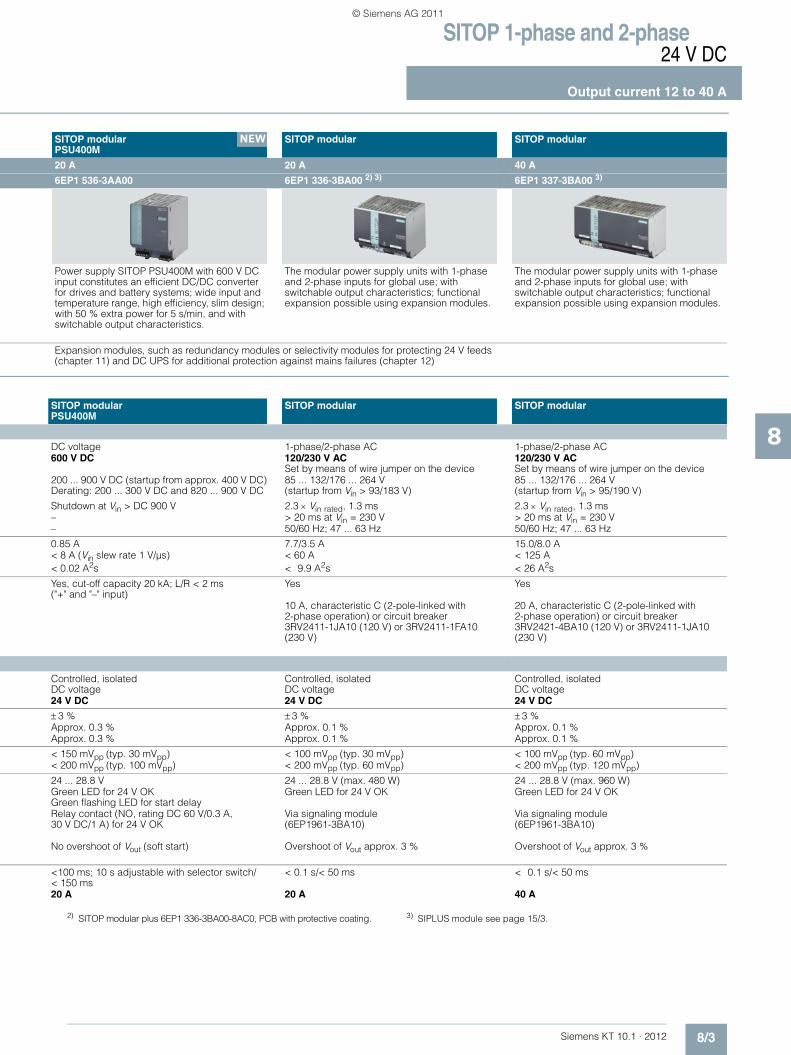
SITOP 1-phase and 2-phase24 V DC
Output current 12 to 40 A
8/3Siemens KT 10.1 · 2012
8
2) SITOP modular plus 6EP1 336-3BA00-8AC0, PCB with protective coating. 3) SIPLUS module see page 15/3.
SITOP modularPSU400M
SITOP modular SITOP modular
20 A 20 A 40 A
6EP1 536-3AA00 6EP1 336-3BA00 2) 3) 6EP1 337-3BA00 3)
Power supply SITOP PSU400M with 600 V DC input constitutes an efficient DC/DC converter for drives and battery systems; wide input and temperature range, high efficiency, slim design; with 50 % extra power for 5 s/min, and with switchable output characteristics.
The modular power supply units with 1-phase and 2-phase inputs for global use; with switchable output characteristics; functional expansion possible using expansion modules.
The modular power supply units with 1-phase and 2-phase inputs for global use; with switchable output characteristics; functional expansion possible using expansion modules.
Expansion modules, such as redundancy modules or selectivity modules for protecting 24 V feeds(chapter 11) and DC UPS for additional protection against mains failures (chapter 12)
SITOP modularPSU400M
SITOP modular SITOP modular
DC voltage 1-phase/2-phase AC 1-phase/2-phase AC 600 V DC 120/230 V AC
Set by means of wire jumper on the device120/230 V ACSet by means of wire jumper on the device
200 ... 900 V DC (startup from approx. 400 V DC)Derating: 200 ... 300 V DC and 820 ... 900 V DC
85 ... 132/176 ... 264 V(startup from Vin > 93/183 V)
85 ... 132/176 ... 264 V(startup from Vin > 95/190 V)
Shutdown at Vin > DC 900 V 2.3 × Vin rated, 1.3 ms 2.3 × Vin rated, 1.3 ms – > 20 ms at Vin = 230 V > 20 ms at Vin = 230 V– 50/60 Hz; 47 ... 63 Hz 50/60 Hz; 47 ... 63 Hz
0.85 A 7.7/3.5 A 15.0/8.0 A< 8 A (Vin slew rate 1 V/µs) < 60 A < 125 A< 0.02 A2s < 9.9 A2s < 26 A2s
Yes, cut-off capacity 20 kA; L/R < 2 ms ("+" and "–" input)
Yes Yes
10 A, characteristic C (2-pole-linked with 2-phase operation) or circuit breaker 3RV2411-1JA10 (120 V) or 3RV2411-1FA10 (230 V)
20 A, characteristic C (2-pole-linked with 2-phase operation) or circuit breaker 3RV2421-4BA10 (120 V) or 3RV2411-1JA10 (230 V)
Controlled, isolatedDC voltage
Controlled, isolatedDC voltage
Controlled, isolatedDC voltage
24 V DC 24 V DC 24 V DC
± 3 % ± 3 % ± 3 %Approx. 0.3 % Approx. 0.1 % Approx. 0.1 %Approx. 0.3 % Approx. 0.1 % Approx. 0.1 %
< 150 mVpp (typ. 30 mVpp) < 100 mVpp (typ. 30 mVpp) < 100 mVpp (typ. 60 mVpp)< 200 mVpp (typ. 100 mVpp) < 200 mVpp (typ. 60 mVpp) < 200 mVpp (typ. 120 mVpp)
24 ... 28.8 V 24 ... 28.8 V (max. 480 W) 24 ... 28.8 V (max. 960 W)Green LED for 24 V OKGreen flashing LED for start delay
Green LED for 24 V OK Green LED for 24 V OK
Relay contact (NO, rating DC 60 V/0.3 A, 30 V DC/1 A) for 24 V OK
Via signaling module (6EP1961-3BA10)
Via signaling module (6EP1961-3BA10)
No overshoot of Vout (soft start) Overshoot of Vout approx. 3 % Overshoot of Vout approx. 3 %
<100 ms; 10 s adjustable with selector switch/< 150 ms
< 0.1 s/< 50 ms < 0.1 s/< 50 ms
20 A 20 A 40 A
NEW
KT10_EN_gesamt.book Seite 3 Mittwoch, 12. Oktober 2011 11:00 11
© Siemens AG 2011
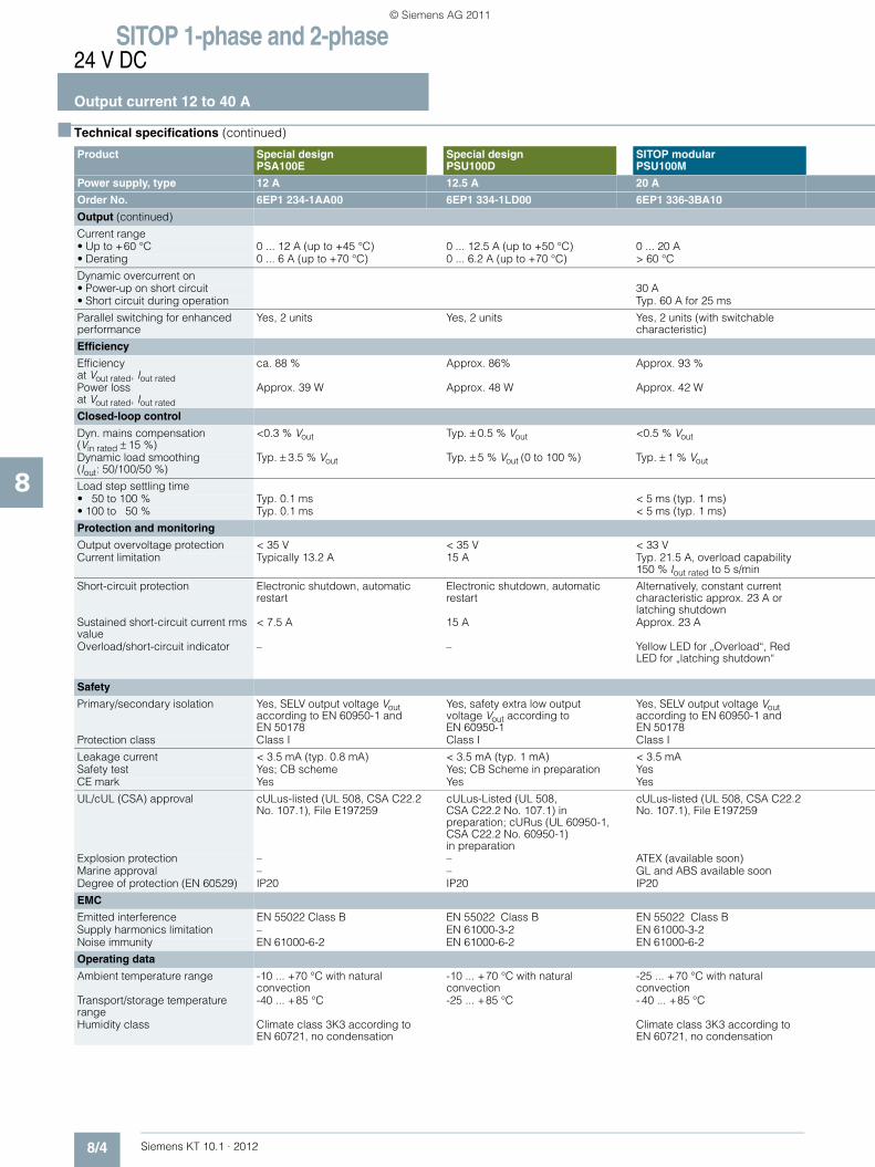
SITOP 1-phase and 2-phase24 V DC
Output current 12 to 40 A
8/4 Siemens KT 10.1 · 2012
8
■ Technical specifications (continued)
Product Special designPSA100E
Special design PSU100D
SITOP modularPSU100M
Power supply, type 12 A 12.5 A 20 A
Order No. 6EP1 234-1AA00 6EP1 334-1LD00 6EP1 336-3BA10
Output (continued)
Current range • Up to +60 °C 0 ... 12 A (up to +45 °C) 0 ... 12.5 A (up to +50 °C) 0 ... 20 A• Derating 0 ... 6 A (up to +70 °C) 0 ... 6.2 A (up to +70 °C) > 60 °C
Dynamic overcurrent on • Power-up on short circuit 30 A• Short circuit during operation Typ. 60 A for 25 ms
Parallel switching for enhanced performance
Yes, 2 units Yes, 2 units Yes, 2 units (with switchable characteristic)
Efficiency
Efficiency at Vout rated, Iout rated
ca. 88 % Approx. 86% Approx. 93 %
Power loss at Vout rated, Iout rated
Approx. 39 W Approx. 48 W Approx. 42 W
Closed-loop control
Dyn. mains compensation (Vin rated ± 15 %)
<0.3 % Vout Typ. ± 0.5 % Vout <0.5 % Vout
Dynamic load smoothing(Iout: 50/100/50 %)
Typ. ± 3.5 % Vout Typ. ± 5 % Vout (0 to 100 %) Typ. ± 1 % Vout
Load step settling time• 50 to 100 % Typ. 0.1 ms < 5 ms (typ. 1 ms)• 100 to 50 % Typ. 0.1 ms < 5 ms (typ. 1 ms)
Protection and monitoring
Output overvoltage protection < 35 V < 35 V < 33 VCurrent limitation Typically 13.2 A 15 A Typ. 21.5 A, overload capability
150 % Iout rated to 5 s/min
Short-circuit protection Electronic shutdown, automatic restart
Electronic shutdown, automatic restart
Alternatively, constant current characteristic approx. 23 A or latching shutdown
Sustained short-circuit current rms value
< 7.5 A 15 A Approx. 23 A
Overload/short-circuit indicator – – Yellow LED for „Overload“, Red LED for „latching shutdown“
Safety
Primary/secondary isolation Yes, SELV output voltage Vout according to EN 60950-1 and EN 50178
Yes, safety extra low output voltage Vout according to EN 60950-1
Yes, SELV output voltage Vout according to EN 60950-1 and EN 50178
Protection class Class I Class I Class I
Leakage current < 3.5 mA (typ. 0.8 mA) < 3.5 mA (typ. 1 mA) < 3.5 mA Safety test Yes; CB scheme Yes; CB Scheme in preparation YesCE mark Yes Yes Yes
UL/cUL (CSA) approval cULus-listed (UL 508, CSA C22.2 No. 107.1), File E197259
cULus-Listed (UL 508, CSA C22.2 No. 107.1) in preparation; cURus (UL 60950-1, CSA C22.2 No. 60950-1) in preparation
cULus-listed (UL 508, CSA C22.2 No. 107.1), File E197259
Explosion protection – – ATEX (available soon)Marine approval – – GL and ABS available soonDegree of protection (EN 60529) IP20 IP20 IP20
EMC
Emitted interference EN 55022 Class B EN 55022 Class B EN 55022 Class BSupply harmonics limitation – EN 61000-3-2 EN 61000-3-2Noise immunity EN 61000-6-2 EN 61000-6-2 EN 61000-6-2
Operating data
Ambient temperature range -10 ... +70 °C with natural convection
-10 ... +70 °C with natural convection
-25 ... +70 °C with natural convection
Transport/storage temperature range
-40 ... +85 °C -25 ... +85 °C - 40 ... +85 °C
Humidity class Climate class 3K3 according to EN 60721, no condensation
Climate class 3K3 according to EN 60721, no condensation
KT10_EN_gesamt.book Seite 4 Mittwoch, 12. Oktober 2011 11:00 11
© Siemens AG 2011

SITOP 1-phase and 2-phase24 V DC
Output current 12 to 40 A
8/5Siemens KT 10.1 · 2012
8
SITOP modularPSU400M
SITOP modular SITOP modular
20 A 20 A 40 A
6EP1 536-3AA00 6EP1 336-3BA00 6EP1 337-3BA00
0 ... 20 A 0 ... 20 A 0 ... 40 A0 ... 9 A (up to +70 °C) > 60 °C > 60 °C
Approx. 40 A for 150 ms Approx. 23 A constant current Approx. 46 A constant current– Typ. 60 A for 25 ms Typ. 120 A for 25 ms
P Yes, (switchable characteristic) Yes, 2 units (switchable characteristic) Yes, 2 units (switchable characteristic)
Approx. 95 % Approx. 89 % Approx. 88 %
Approx. 25 W Approx. 59 W Approx. 131 W
<1.5 % Vout <1% Vout <1% Vout
Typ. ± 1.5 % Vout Typ. ± 2 % Vout Typ. ± 2 % Vout
< 5 ms (typ. 1 ms) < 5 ms (typ. 2 ms) < 5 ms (typ. 2 ms)< 5 ms (typ. 1 ms) < 5 ms (typ. 2 ms) < 5 ms (typ. 2 ms)
< 33 V < 35 V < 35 VTyp. 22 A, overload capability 150 % Iout rated to 5 s/min
Typ. 23 A Typically 46 A
Alternatively, constant current characteristic approx. 22 A or latching shutdown
Alternatively, constant current characteristic approx. 23 A or latching shutdown
Alternatively, constant current characteristic approx. 46 A or latching shutdown
Approx. 22 A Approx. 23 A Approx. 46 A
Yellow LED for „Overload“, red LED for „latching shutdown“, Red LED flashing for "overtemperature"
Yellow LED for „Overload“, Red LED for „latching shutdown“
Yellow LED for „Overload“, Red LED for „latching shutdown“
Yes, SELV output voltage Vout according to EN 60950-1 and EN 50178
Yes, SELV output voltage Vout according to EN 60950-1 and EN 50178
Yes, SELV output voltage Vout according to EN 60950-1 and EN 50178
Class I Class I Class I
– < 3.5 mA (typ. 0.4 mA) < 3.5 mA (typ. 0.4 mA)Yes Yes YesYes Yes Yes
cULus-Listed (UL 508, CSA C22.2 No. 107.1), File E197259
cULus-listed (UL 508, CSA C22.2 No. 107.1), File E197259
cULus-listed (UL 508, CSA C22.2 No. 107.1), File E197259
IP20 IP20 IP20– ATEX (available soon) –GL and ABS available soon GL and ABS available soon –
EN 55022 Class A (radiated emission) EN 55022 Class B EN 55022 Class B– EN 61000-3-2 –EN 61000-6-2 EN 61000-6-2 EN 61000-6-2
-25 ... +70 °C with natural convection 0 ... +70 °C with natural convection 0 ... +70 °C with natural convection
-40 ... +85 °C -40 ... +85 °C -40 ... +85 °C
Climate class 3K3 according to EN 60721, no condensation
Climate class 3K3 according to EN 60721, no condensation
Climate class 3K3 according to EN 60721, no condensation
KT10_EN_gesamt.book Seite 5 Mittwoch, 12. Oktober 2011 11:00 11
© Siemens AG 2011
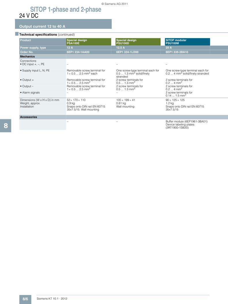
SITOP 1-phase and 2-phase24 V DC
Output current 12 to 40 A
8/6 Siemens KT 10.1 · 2012
8
■ Technical specifications (continued)
Product Special designPSA100E
Special design PSU100D
SITOP modularPSU100M
Power supply, type 12 A 12.5 A 20 A
Order No. 6EP1 234-1AA00 6EP1 334-1LD00 6EP1 336-3BA10
Mechanics
Connections • DC input +, –, PE – – –
• Supply input L, N, PE Removable screw terminal for 1 × 0.5 ... 2.5 mm2 each
One screw-type terminal each for 0.5 ... 1.3 mm2 solid/finely stranded
One screw-type terminal each for 0.2 ... 4 mm2 solid/finely stranded
• Output + Removable screw terminal for 1 × 0.5 ... 2.5 mm2
2 screw terminals for 0.5 ... 1.3 mm2
2 screw terminals for 0.2 ... 4 mm2
• Output – Removable screw terminal for 1 × 0.5 ... 2.5 mm2
2 screw terminals for 0.5 ... 1.3 mm2
2 screw terminals for 0.2 ... 4 mm2
• Alarm signals – – 2 screw terminals for 0.14 ... 1.5 mm2
Dimensions (W x H x D) in mm 52 × 170 × 110 105 × 199 × 41 90 × 125 × 125Weight, approx. 0.9 kg 0.81 kg 1.2 kgInstallation Snaps onto DIN rail EN 60715
35x7.5/15. Wall mounting Wall mounting Snaps onto DIN rail EN 60715
35x7.5/15
Accessories
– – Buffer module (6EP1961-3BA01) Device labeling plates (3RT1900-1SB20)
KT10_EN_gesamt.book Seite 6 Mittwoch, 12. Oktober 2011 11:00 11
© Siemens AG 2011
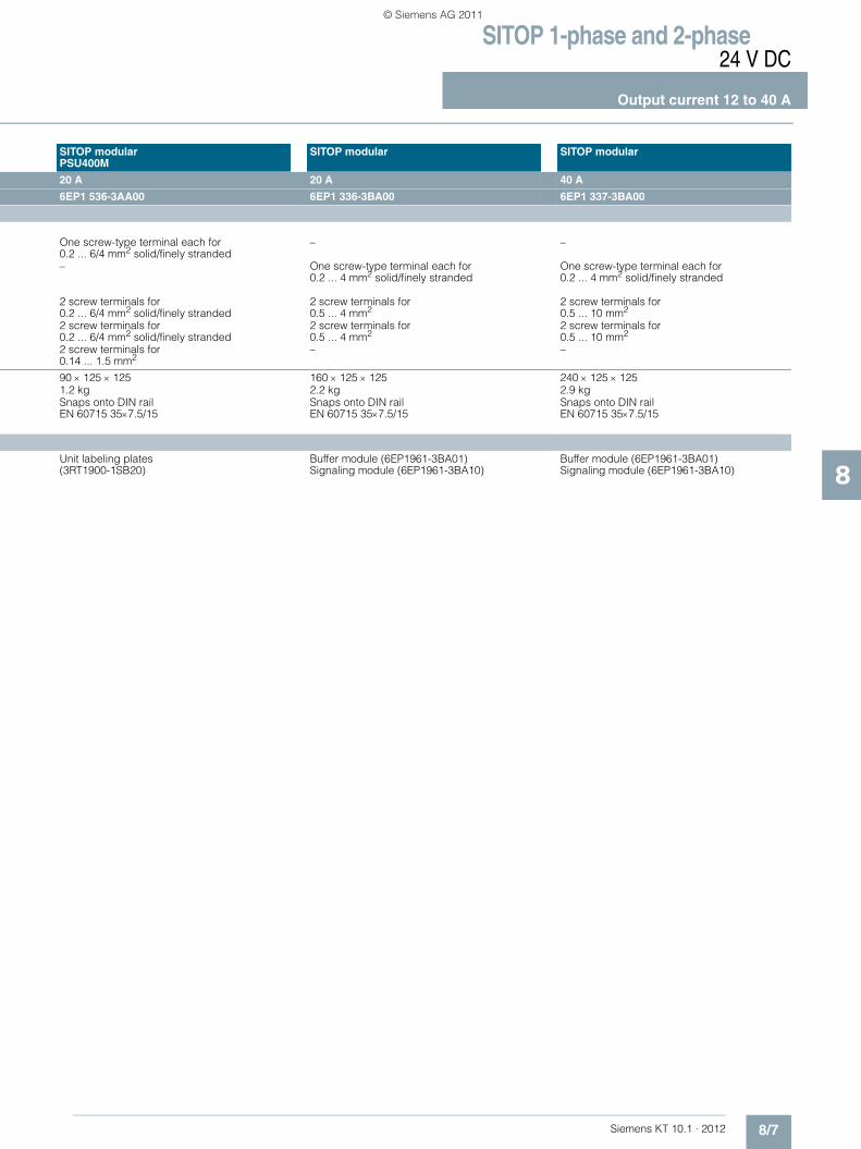
SITOP 1-phase and 2-phase24 V DC
Output current 12 to 40 A
8/7Siemens KT 10.1 · 2012
8
SITOP modularPSU400M
SITOP modular SITOP modular
20 A 20 A 40 A
6EP1 536-3AA00 6EP1 336-3BA00 6EP1 337-3BA00
One screw-type terminal each for 0.2 ... 6/4 mm2 solid/finely stranded
– –
– One screw-type terminal each for 0.2 ... 4 mm2 solid/finely stranded
One screw-type terminal each for 0.2 ... 4 mm2 solid/finely stranded
2 screw terminals for 0.2 ... 6/4 mm2 solid/finely stranded
2 screw terminals for 0.5 ... 4 mm2
2 screw terminals for 0.5 ... 10 mm2
2 screw terminals for 0.2 ... 6/4 mm2 solid/finely stranded
2 screw terminals for 0.5 ... 4 mm2
2 screw terminals for 0.5 ... 10 mm2
2 screw terminals for 0.14 ... 1.5 mm2
– –
90 × 125 × 125 160 × 125 × 125 240 × 125 × 1251.2 kg 2.2 kg 2.9 kgSnaps onto DIN rail EN 60715 35×7.5/15
Snaps onto DIN rail EN 60715 35×7.5/15
Snaps onto DIN rail EN 60715 35×7.5/15
Unit labeling plates (3RT1900-1SB20)
Buffer module (6EP1961-3BA01) Signaling module (6EP1961-3BA10)
Buffer module (6EP1961-3BA01) Signaling module (6EP1961-3BA10)
KT10_EN_gesamt.book Seite 7 Mittwoch, 12. Oktober 2011 11:00 11
© Siemens AG 2011
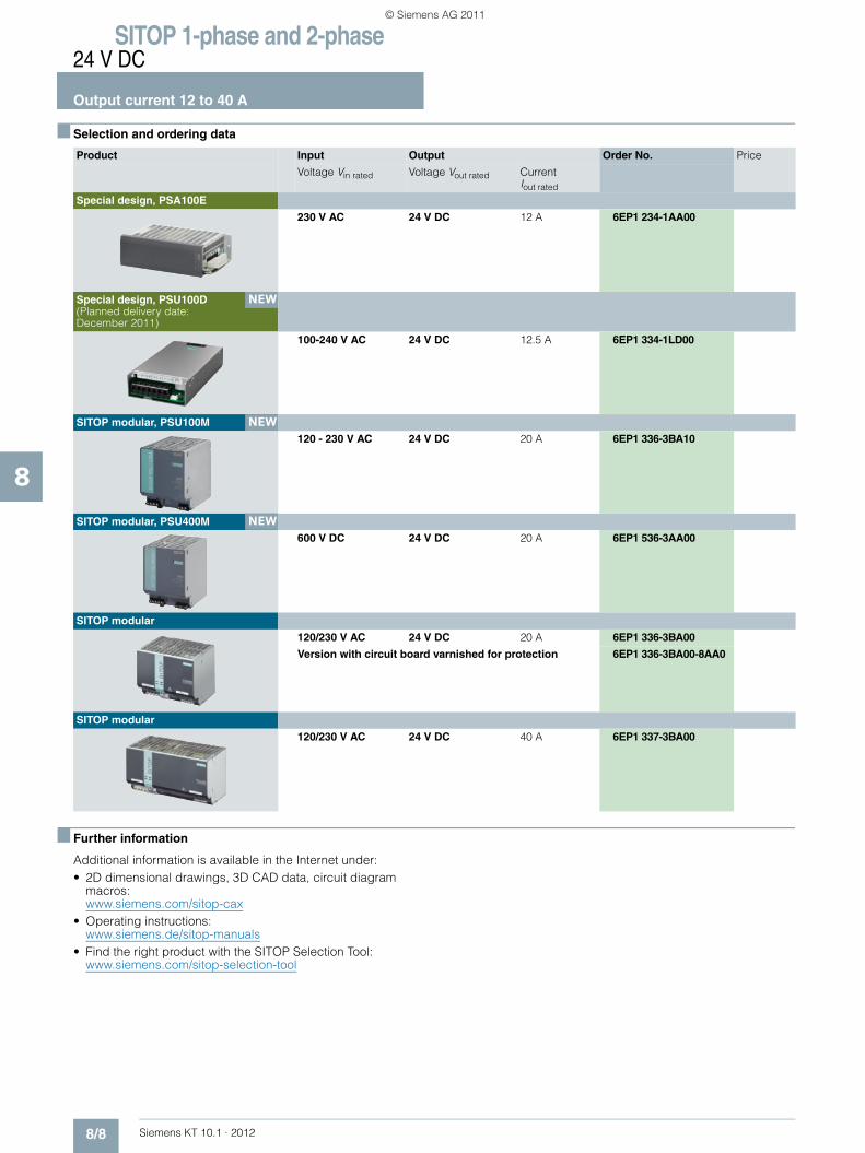
SITOP 1-phase and 2-phase24 V DC
Output current 12 to 40 A
8/8 Siemens KT 10.1 · 2012
8
■ Selection and ordering data
■ Further information
Additional information is available in the Internet under:• 2D dimensional drawings, 3D CAD data, circuit diagram
macros: www.siemens.com/sitop-cax
• Operating instructions:www.siemens.de/sitop-manuals
• Find the right product with the SITOP Selection Tool: www.siemens.com/sitop-selection-tool
Product Input Output Order No. Price
Voltage Vin rated Voltage Vout rated Current Iout rated
Special design, PSA100E
230 V AC 24 V DC 12 A 6EP1 234-1AA00
Special design, PSU100D (Planned delivery date: December 2011)
100-240 V AC 24 V DC 12.5 A 6EP1 334-1LD00
SITOP modular, PSU100M
120 - 230 V AC 24 V DC 20 A 6EP1 336-3BA10
SITOP modular, PSU400M
600 V DC 24 V DC 20 A 6EP1 536-3AA00
SITOP modular
120/230 V AC 24 V DC 20 A 6EP1 336-3BA00
Version with circuit board varnished for protection 6EP1 336-3BA00-8AA0
SITOP modular
120/230 V AC 24 V DC 40 A 6EP1 337-3BA00
NEW
NEW
NEW
KT10_EN_gesamt.book Seite 8 Mittwoch, 12. Oktober 2011 11:00 11
© Siemens AG 2011

Siemens KT 10.1 · 2012
99/2 SITOP modular 5 A9/2 SITOP PSU300P 8 A9/2 SITOP modular 10 A9/3 SITOP PSU300S 10 A9/3 SITOP PSU300M 20 A9/3 SITOP modular 20 A9/3 SITOP PSU300S 20 A9/6 Ordering data and additional information
SITOP 3-phase 24 V DC, 5 to 20 A
Export regulations AL and ECCNsee page 17/9
KT10_EN_gesamt.book Seite 1 Mittwoch, 12. Oktober 2011 11:00 11
© Siemens AG 2011

SITOP 3-phase24 V DC
Output current 5 to 20 A
9/2 Siemens KT 10.1 · 2012
9
■ Overview
■ Technical specifications
1) Available with a second plug connector for loop-through of the input voltage as 2) SIPLUS module see page 15/4SIMATIC ET 200pro PS (6ES7148-4PC00-0HA0), output "PELV".
Product SITOP modular Special designPSU300P
SITOP modular
Power supply, type 5 A 8 A 10 AOrder No. 6EP1 333-3BA00 2) 6EP1 433-2CA00 6EP1 334-3BA00 2)
The product families are highlighted in the same color.For an explanation of the product families, see chapter 1, pages 1/8 through 1/12.
The modular power supply units with wide-range input for 2-phase connection to three-phase supply networks; for global use; with switchable output characteristics; functional expansion possible using expansion modules.
The power supplies with IP67 degree of protection, SITOP PSU300P and SIMATIC ET 200pro PS 1), serve as electronics/encoder and load power supplies for the new I/O device. With a signaling contact for "24 V OK" and "Overtemperature", and in the case of SIMATIC ET 200pro with a second plug-in connector for input voltage loop-through.
The modular power supply units with wide-range input for 2-phase connection to three-phase supply networks; for global use; with switchable output characteristics; functional expansion possible using expansion modules.
Expansion possibilities Expansion modules, such as redundancy modules or selectivity modules for protecting 24 V feeds(chapter 11) and DC UPS for additional protection against mains failures (chapter 12).
Product SITOP modular Special design PSU300P SITOP modular
Input 2-phase AC 3-phase AC 2-phase AC
Rated voltage value Vin rated 120-230/230-500 V 2 AC Set with selector switch on device
400-480 V 3 AC Wide-range input
120-230/230-500 V 2 AC Set with selector switch on device
Voltage range 85 ... 264/176 ... 550 V 340 ... 550 V(320 ... 340 V for max. 1 min)
85 ... 264/176 ... 550 V
Overvoltage resistance 1300 Vpeak, 1.3 ms Internal, with varistors 1300 Vpeak, 1.3 ms Mains buffering at Iout rated Typ. 150 ms at Vin = 400 V > 15 ms at Vin = 400 V Typ. 120 ms at Vin = 400 VRated line frequency value; range 50/60 Hz; 47 ... 63 Hz 50/60 Hz; 45 ... 66 Hz 50/60 Hz; 47 ... 63 HzRated current Iin rated 2.2-1.2/1.2-0.61 A 0.5 A (at Vin 400 V) 4.4-2.4/2.4-1.1 ASwitch-on current limit (+25 °C) < 35 A < 40 A < 35 AI2t < 1.7 A2s < 3.5 A2s < 4.0 A2s
Built-in incoming fuse T 3.15 A Intern, 4 A T 6.3 ARequired protection in the main supply conductor
From 6 A (10 A) characteristic C (B); required for two-phase operation: Miniature circuit-breaker 2-pole coupled or circuit-breaker 3RV2011-1EA10 (setting 3.8 A) or 3RV2711-1ED10 (UL 489) at 230 V; 3RV2011-1DA10 (setting 3 A) or 3RV2711-1DD10 (UL 489) at 400/500 V
Circuit breaker 2.2 ... 3.2 A3RV2011-1DA10 or3RV2711-1DD10 (UL 489)
From 6 A (10 A) characteristic C (B); required for two-phase operation: Miniature circuit-breaker 2-pole coupled or circuit-breaker 3RV2011-1EA10 (setting 3.8 A) or 3RV2711-1ED10 (UL 489) at 230 V; 3RV2011-1DA10 (setting 3 A) or 3RV2711-1DD10 (UL 489) at 400/500 V
Output Controlled, isolated DC voltage Controlled, isolated DC voltage Controlled, isolated DC voltage
Rated voltage Vout rated 24 V DC 24 V DC 24 V DCTotal tolerance ± 3 % < ± 3 ... -5 % ± 3 %• Static line compensation Approx. 0.1 % Approx. 0.5 % Approx. 0.1 %• Static load compensation Approx. 0.1 % Approx. 0.5 % Approx. 0.1 %Residual ripple < 50 mVpp < 200 mVpp < 50 mVpp Spikes (bandwidth: 20 MHz) < 200 mVpp < 250 mVpp < 200 mVpp Adjustment range 24 ... 28.8 V (max. 120 W) – 24 ... 28.8 V (max. 240 W)Status display Green LED for 24 V OK Green LED for 24 V OK Green LED for 24 V OKSignaling Use signaling module
(6EP1961-3BA10)• Power Good (high level 1L+ for
Vout in range 21.3 ... 29 V)• Overtemperature warning at
least 30 s before switch-off (High level 1L+ when the max. internal temperature is exceeded)
Use signaling module (6EP1961-3BA10)
On/off behavior Overshoot of Vout approx. 3 % Overshoot of Vout <2 % Overshoot of Vout approx. 3 %Startup delay/voltage rise < 1 s/< 50 ms < 1.5 s/< 400 ms < 1 s/< 50 msRated current value Iout rated 5 A 8 A 10 ACurrent range • Up to +60 °C 0 ... 5 A 0 ... 8 A (up to +55 °C) 0 ... 10 A• Derating > 60 °C – > 60 °C
KT10_EN_gesamt.book Seite 2 Mittwoch, 12. Oktober 2011 11:00 11
© Siemens AG 2011
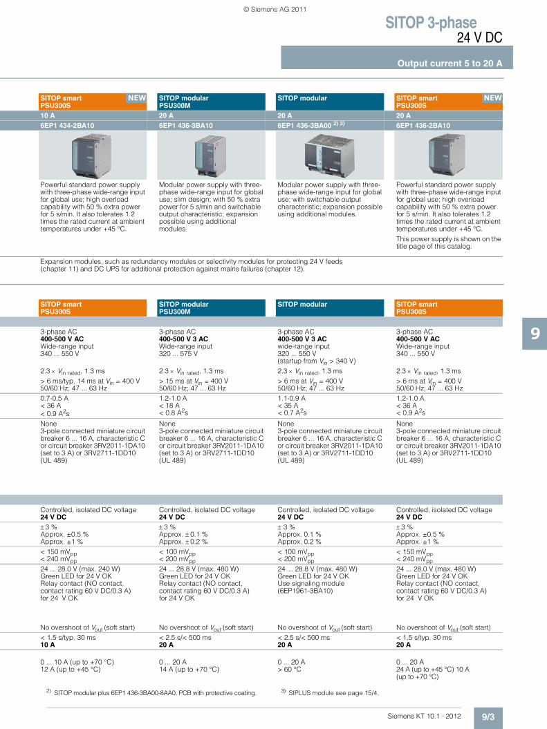
SITOP 3-phase24 V DC
Output current 5 to 20 A
9/3Siemens KT 10.1 · 2012
9
2) SITOP modular plus 6EP1 436-3BA00-8AA0, PCB with protective coating. 3) SIPLUS module see page 15/4..
SITOP smartPSU300S
SITOP modularPSU300M
SITOP modular SITOP smartPSU300S
10 A 20 A 20 A 20 A6EP1 434-2BA10 6EP1 436-3BA10 6EP1 436-3BA00 2) 3) 6EP1 436-2BA10
Powerful standard power supply with three-phase wide-range input for global use; high overload capability with 50 % extra power for 5 s/min. It also tolerates 1.2 times the rated current at ambient temperatures under +45 °C.
Modular power supply with three-phase wide-range input for global use; slim design; with 50 % extra power for 5 s/min and switchable output characteristic; expansion possible using additional modules.
Modular power supply with three-phase wide-range input for global use; with switchable output characteristic; expansion possible using additional modules.
Powerful standard power supply with three-phase wide-range input for global use; high overload capability with 50 % extra power for 5 s/min. It also tolerates 1.2 times the rated current at ambient temperatures under +45 °C. This power supply is shown on the title page of this catalog.
Expansion modules, such as redundancy modules or selectivity modules for protecting 24 V feeds(chapter 11) and DC UPS for additional protection against mains failures (chapter 12).
SITOP smartPSU300S
SITOP modularPSU300M
SITOP modular SITOP smartPSU300S
3-phase AC 3-phase AC 3-phase AC 3-phase AC400-500 V AC Wide-range input
400-500 V 3 AC Wide-range input
400-500 V 3 AC wide-range input
400-500 V AC Wide-range input
340 ... 550 V 320 ... 575 V 320 ... 550 V(startup from Vin > 340 V)
340 ... 550 V
2.3 × Vin rated, 1.3 ms 2.3 × Vin rated, 1.3 ms 2.3 × Vin rated, 1.3 ms 2.3 × Vin rated, 1.3 ms> 6 ms/typ. 14 ms at Vin = 400 V > 15 ms at Vin = 400 V > 6 ms at Vin = 400 V > 6 ms at Vin = 400 V50/60 Hz; 47 ... 63 Hz 50/60 Hz; 47 ... 63 Hz 50/60 Hz; 47 ... 63 Hz 50/60 Hz; 47 ... 63 Hz0.7-0.5 A 1.2-1.0 A 1.1-0.9 A 1.2-1.0 A< 36 A < 18 A < 35 A < 36 A< 0.9 A2s < 0.8 A2s < 0.7 A2s < 0.9 A2s
None None None None3-pole connected miniature circuit breaker 6 ... 16 A, characteristic C or circuit breaker 3RV2011-1DA10 (set to 3 A) or 3RV2711-1DD10 (UL 489)
3-pole connected miniature circuit breaker 6 ... 16 A, characteristic C or circuit breaker 3RV2011-1DA10 (set to 3 A) or 3RV2711-1DD10 (UL 489)
3-pole connected miniature circuit breaker 6 ... 16 A, characteristic C or circuit breaker 3RV2011-1DA10 (set to 3 A) or 3RV2711-1DD10 (UL 489)
3-pole connected miniature circuit breaker 6 ... 16 A, characteristic C or circuit breaker 3RV2011-1DA10 (set to 3 A) or 3RV2711-1DD10 (UL 489)
Controlled, isolated DC voltage Controlled, isolated DC voltage Controlled, isolated DC voltage Controlled, isolated DC voltage24 V DC 24 V DC 24 V DC 24 V DC ± 3 % ± 3 % ± 3 % ± 3 %Approx. ±0.5 % Approx. ± 0.1 % Approx. 0.1 % Approx. ±0.5 %Approx. ±1 % Approx. ± 0.2 % Approx. 0.2 % Approx. ±1 %< 150 mVpp < 100 mVpp < 100 mVpp < 150 mVpp< 240 mVpp < 200 mVpp < 200 mVpp < 240 mVpp
24 ... 28.0 V (max. 240 W) 24 ... 28.8 V (max. 480 W) 24 ... 28.8 V (max. 480 W) 24 ... 28.0 V (max. 480 W)Green LED for 24 V OK Green LED for 24 V OK Green LED for 24 V OK Green LED for 24 V OKRelay contact (NO contact, contact rating 60 V DC/0.3 A) for 24 V OK
Relay contact (NO contact, contact rating 60 V DC/0.3 A) for 24 V OK
Use signaling module (6EP1961-3BA10)
Relay contact (NO contact, contact rating 60 V DC/0.3 A) for 24 V OK
No overshoot of Vout (soft start) No overshoot of Vout (soft start) No overshoot of Vout (soft start) No overshoot of Vout (soft start)< 1.5 s/typ. 30 ms < 2.5 s/< 500 ms < 2.5 s/< 500 ms < 1.5 s/typ. 30 ms10 A 20 A 20 A 20 A
0 ... 10 A (up to +70 °C) 0 ... 20 A 0 ... 20 A 0 ... 20 A12 A (up to +45 °C) 14 A (up to +70 °C) > 60 °C 24 A (up to +45 °C) 10 A
(up to +70 °C)
NEW NEW
KT10_EN_gesamt.book Seite 3 Mittwoch, 12. Oktober 2011 11:00 11
© Siemens AG 2011

SITOP 3-phase24 V DC
Output current 5 to 20 A
9/4 Siemens KT 10.1 · 2012
9
Product SITOP modular Special designPSU300P
SITOP modular
Power supply, type 5 A 8 A 10 AOrder No. 6EP1 333-3BA00 6EP1 433-2CA00 6EP1 334-3BA00Output Dynamic overcurrent on • Power-up on short circuit Approx. 5.5 A constant current Approx. 50 A for 100 ms Approx. 12 A constant current• Short circuit during operation Typ. 15 A for 25 ms Approx. 50 A for 100 ms Typ. 30 A for 25 msParallel switching for enhanced performance
Yes, 2 units (switchable characteristic)
No Yes, 2 units (switchable characteristic)
Efficiency Efficiency at Vout rated, Iout rated Approx. 87 % Typically 88 % Approx. 87 %Power loss at Vout rated, Iout rated Approx. 18 W Typ. 25 W Approx. 36 WClosed-loop control Dyn. mains compensation (Vin rated ± 15 %)
Typ. 0.1 % Vout Approx. 0.5 % Vout Typ. 0.1 % Vout
Dynamic load smoothing(Iout: 50/100/50 %)
Typ. +3 % Vout Typ. ± 1 % Vout Typ. +3 % Vout
Load step settling time• 50 to 100 % < 5 ms (typ. 2 ms) < 2 ms < 5 ms (typ. 2 ms)• 100 to 50 % < 5 ms (typ. 2 ms) < 2 ms < 5 ms (typ. 2 ms)Protection and monitoring Output overvoltage protection < 35 V < 33 V < 35 VCurrent limitation Typically 5.5 A Typically 9.4 A Typically 12 A
Short-circuit protection Alternatively, constant current characteristic approx. 5.5 A or latching shutdown
Electronic shutdown, automatic restart
Alternatively, constant current characteristic approx. 12 A or latching shutdown
Sustained short-circuit rms value Approx. 5.5 A < 10 A Approx. 12 AOverload/short-circuit indicator LED yellow for "overload", LED red
for "latching shutdown"– LED yellow for "overload", LED red
for "latching cutoff"Safety Primary/secondary isolation Yes, SELV output voltage Vout
according to EN 60950-1 and EN 50178
Yes, SELV output voltage Vout according to EN 60950-1 and EN 50178
Yes, SELV output voltage Vout according to EN 60950-1 and EN 50178
Protection class Class I Class I Class ILeakage current < 3.5 mA (typ. 0.25 mA) < 3.5 mA < 3.5 mA (typ. 0.32 mA)Safety test Yes Yes; CB scheme YesCE mark Yes Yes YesUL/cUL (CSA) approval cULus-listed (UL 508, CSA C22.2
No. 107.1), File E197259In preparation: UL-Listed (UL 508) cULus-listed (UL 508, CSA C22.2
No. 107.1), File E197259
Explosion protection ATEX (available soon) – ATEX (available soon)Marine approval GL and ABS available soon – GL and ABS available soonDegree of protection (EN 60529) IP20 IP67, enclosure type 4 indoor IP20EMC Emitted interference EN 55022 Class B EN 55022 Class A EN 55022 Class BSupply harmonics limitation EN 61000-3-2 – EN 61000-3-2Noise immunity EN 61000-6-2 EN 61000-6-2 EN 61000-6-2Operating data Ambient temperature range -25 ... +70 °C with natural
convection-25 ... +55 °C with natural convection
-25 ... +70 °C with natural convection
Transport and storage temperature -40 ... +85 °C -40 ... +70 °C -40 ... +85 °CHumidity class Climate class 3K3 according to
EN 60721, no condensationClimate class 3K3 according to EN 60721, no condensation
Climate class 3K3 according to EN 60721, no condensation
Mechanics Connections • Supply input L1, L2. L3, PE One screw-type terminal each for
0.2 ... 2.5 mm2 solid/finely stranded
Plug connector HAN Q4/2 One screw-type terminal each for 0.2 ... 2.5 mm2 solid/finely stranded
• Output + 2 screw terminals for 0.2 ... 2.5 mm2
1 × 2.5 mm2 (2-pole cable for +/- with open, labeled ends, 2 × 2.5 mm2)
2 screw terminals for 0.2 ... 2.5 mm2
• Output – 2 screw terminals for 0.2 ... 2.5 mm2
1 × 2.5 mm2 (2-pole cable for +/- with open, labeled ends, 2 × 2.5 mm2)
2 screw terminals for 0.2 ... 2.5 mm2
• Alarm signals – M12 plug-in connector, 5-pin –
Dimensions (W x H x D) in mm 70 × 125 × 125 310 × 135 × 90 + additional height of connector
90 × 125 × 125
Weight, approx. 1.2 kg 2.8 kg 1.4 kgInstallation Snaps onto DIN rail EN 60715
35x7.5/15Can be mounted onto ET 200pro mounting rail
Snaps onto DIN rail EN 60715 35x7.5/15
Accessories Buffer module (6EP1961-3BA01) Signaling module (6EP1961-3BA10)
Power connector (3RK1911-2BE50 (2.5 mm2))
Buffer module (6EP1961-3BA01) Signaling module (6EP1961-3BA10)
KT10_EN_gesamt.book Seite 4 Mittwoch, 12. Oktober 2011 11:00 11
© Siemens AG 2011

SITOP 3-phase24 V DC
Output current 5 to 20 A
9/5Siemens KT 10.1 · 2012
9
SITOP smartPSU300S
SITOP modularPSU300M
SITOP modular SITOP smartPSU300S
10 A 20 A 20 A 20 A6EP1 434-2BA10 6EP1 436-3BA10 6EP1 436-3BA00 6EP1 436-2BA10
Approx. 16 A for 100 ms Approx. 23 A constant current Approx. 23 A constant current Approx. 35 A for 100 msApprox. 16 A for 100 ms Typ. 60 A for 25 ms Typ. 60 A for 25 ms Approx. 35 A for 100 msYes, 2 units Yes, 2 units
(switchable characteristic)Yes, 2 units (switchable characteristic)
Yes, 2 units
Approx. 91 % Approx. 93 % Approx. 90 % Approx. 91 %Approx. 24 W Approx. 36 W Approx. 53 W Approx. 47 W
<3 % Vout <1% Vout <1% Vout <3 % Vout
Typ. ± 3 % Vout Typ. ±2 % Vout Typ. ±2 % Vout Typ. ± 3 % Vout
< 10 ms (typ. 2 ms) < 10 ms (typ. 2 ms) < 10 ms (typ. 4 ms) < 10 ms (typ. 2 ms)< 10 ms (typ. 2 ms < 10 ms (typ. 2 ms) < 10 ms (typ. 4 ms) < 10 ms (typ. 2 ms
Yes, according to EN 60950 < 35 V < 35 V Yes, according to EN 60950Typ. 11 A, overload capability 150 % Iout rated up to 5 s/min
Typ. 23 A, overload capability 150 % Iout rated up to 5 s/min
Typically 23 A Typ. 25 A, overload capability 150 % Iout rated up to 5 s/min
Electronic shutdown, automatic restart
Alternatively, constant current characteristic approx. 23 A or latching shutdown
Alternatively, constant current characteristic approx. 23 A or latching shutdown
Electronic shutdown, automatic restart
Approx. 3.2 A Approx. 23 A Approx. 23 A Approx. 7 A– LED yellow for "overload", LED red
for "latching cutoff"LED yellow for "overload", LED red for "latching cutoff"
–
Yes, SELV output voltage Vout according to EN 60950-1 and EN 50178
Yes, SELV output voltage Vout according to EN 60950-1 and EN 50178
Yes, SELV output voltage Vout according to EN 60950-1 and EN 50178
Yes, SELV output voltage Vout according to EN 60950-1 and EN 50178
Class I Class I Class I Class I< 3.5 mA (typ. 1 mA) < 3.5 mA < 3.5 mA < 3.5 mA mA (typ. 1 mA)Yes; CB scheme Yes Yes Yes; CB schemeYes Yes Yes YescULus-Listed (UL 508, CSA C22.2 No. 107.1) File E197259; cCSAus (CSA C22.2 No. 60950-1, UL 60950-1)
cULus-listed (UL 508, CSA C22.2 No. 107.1), File E197259
UL-listed (UL 508) File E197259, CSA (CSA C22.2 No. 14, CSA C22.2 No. 107.1)
cULus-Listed (UL 508, CSA C22.2 No. 107.1) File E197259; cCSAus (CSA C22.2 No. 60950-1, UL 60950-1)
ATEX (EX) II 3G Ex nAC IIC T4 ATEX (available soon) ATEX (available soon) ATEX (EX) II 3G Ex nAC IIC T4GL in preparation GL and ABS available soon GL and ABS available soon GL in preparationIP20 IP20 IP20 IP20
EN 55022 Class B EN 55022 Class B EN 55022 Class B EN 55022 Class B EN 61000-3-2 EN 61000-3-2 EN 61000-3-2 EN 61000-3-2EN 61000-6-2 EN 61000-6-2 EN 61000-6-2 EN 61000-6-2
0 ... +70 °C with natural convection
-25 ... +70 °C with natural convection
0 ... +70 °C with natural convection
0 ... +70 °C with natural convection
-40 ... +85 °C -40 ... +85 °C -40 ... +85 °C -40 ... +85 °CClimate class 3K3 according to EN 60721, no condensation
Climate class 3K3 according to EN 60721, no condensation
Climate class 3K3 according to EN 60721, no condensation
Climate class 3K3 according to EN 60721, no condensation
One screw-type terminal each for 0.2 ... 4 mm2 solid/finely stranded
One screw terminal each for 0.2 ... 4 mm2 solid/finely stranded
One screw terminal each for 0.2 ... 4 mm² single-core/finely stranded
One screw-type terminal each for 0.2 ... 4 mm2 solid/finely stranded
2 screw terminals for 0.2 ... 4 mm2
2 screw terminals for 0.2 ... 4 mm2
2 screw terminals for 0.33 to 4 mm²
2 screw terminals for 0.2 ... 4 mm2
2 screw terminals for 0.2 ... 4 mm2
2 screw terminals for 0.2 ... 4 mm2
2 screw terminals for 0.33 ... 4 mm2
2 screw terminals for 0.2 ... 4 mm2
2 screw terminals for 0.14 ... 1.5 mm2
2 screw terminals for 0.14 ... 1.5 mm2
– 2 screw terminals for 0.14 ... 1.5 mm2
90 × 145 × 150 70 × 125 × 125 160 × 125 × 125 90 × 145 × 150
1.6 kg 1.2 kg 2 kg 1.6 kgSnaps onto DIN rail EN 60715 35x7.5/15
Snaps onto DIN rail EN 60715 35x7.5/15
Snaps onto DIN rail EN 60715 35x7.5/15
Snaps onto DIN rail EN 60715 35x7.5/15
Device labeling plates (3RT1900-1SB20)
Buffer module (6EP1961-3BA01) Device labeling plates (3RT1900-1SB20)
Buffer module (6EP1961-3BA01) Signaling module (6EP1961-3BA10)
Device labeling plates (3RT1900-1SB20)
KT10_EN_gesamt.book Seite 5 Mittwoch, 12. Oktober 2011 11:00 11
© Siemens AG 2011

SITOP 3-phase24 V DC
Output current 5 to 20 A
9/6 Siemens KT 10.1 · 2012
9
■ Selection and ordering data
■ Further information
Additional information is available in the Internet under:• 2D dimensional drawings, 3D CAD data, circuit diagram
macros: www.siemens.com/sitop-cax
• Operating instructions:www.siemens.de/sitop-manuals
• Find the right product with the SITOP Selection Tool: www.siemens.com/sitop-selection-tool
Product Input Output Order No. Price
Voltage Vin rated Voltage Vout rated Current Iout rated
SITOP modular
120-230/230-500 V 2 AC
24 V DC 5 A 6EP1 333-3BA00
Special design, PSU300P
400-480 V 3 AC
24 V DC 8 A 6EP1 433-2CA00
Special design, SIMATIC ET 200pro PS
400-480 V 3 AC
24 V DC 8 A 6ES7 148-4PC00-0HA0
SITOP modular
120-230/230-500 V2 AC
24 V DC 10 A 6EP1 334-3BA00
SITOP smart, PSU300S
400-500 V 3 AC
24 V DC 10 A 6EP1 434-2BA10
SITOP modular, PSU300M
400-500 V 3 AC
24 V DC 20 A 6EP1 436-3BA10
Version with circuit board varnished for protection 6EP1 436-3BA00-8AA0
SITOP modular
400-500 V 3 AC
24 V DC 20 A 6EP1 436-3BA00
SITOP smart, PSU300S
400-500 V 3 AC
24 V DC 20 A 6EP1 436-2BA10
NEW
NEW
KT10_EN_gesamt.book Seite 6 Mittwoch, 12. Oktober 2011 11:00 11
© Siemens AG 2011
Siemens KT 10.1 · 2012
1010/2 SITOP PSU300B 30 A10/2 SITOP PSU300M 40 A10/3 SITOP modular 40 A10/3 SITOP PSU300S 40 A10/6 Ordering data and additional information
SITOP 3-phase 24 V DC, 30 to 40 A
Export regulations AL and ECCNsee page 17/9
KT10_EN_gesamt.book Seite 1 Mittwoch, 12. Oktober 2011 11:00 11
© Siemens AG 2011
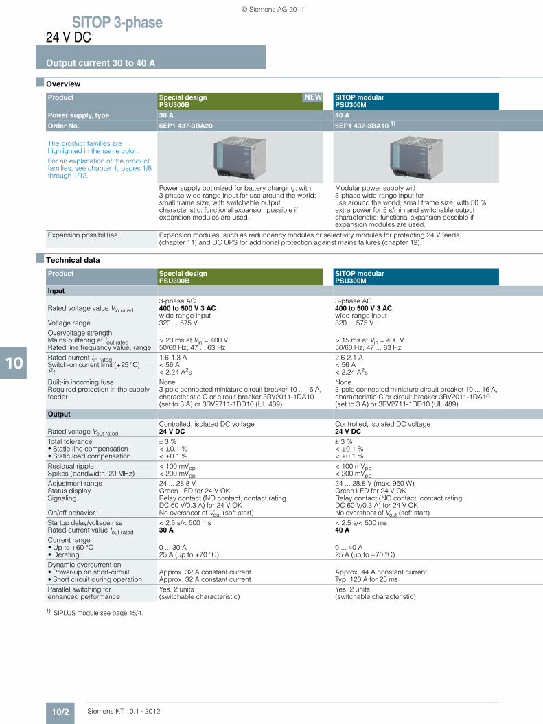
SITOP 3-phase24 V DC
Output current 30 to 40 A
10/2 Siemens KT 10.1 · 2012
10
■ Overview
■ Technical data
1) SIPLUS module see page 15/4.
Product Special designPSU300B
SITOP modularPSU300M
Power supply, type 30 A 40 A
Order No. 6EP1 437-3BA20 6EP1 437-3BA10 1)
The product families are highlighted in the same color.For an explanation of the product families, see chapter 1, pages 1/8 through 1/12.
Power supply optimized for battery charging, with 3-phase wide-range input for use around the world; small frame size; with switchable output characteristic; functional expansion possible if expansion modules are used.
Modular power supply with 3-phase wide-range input for use around the world; small frame size; with 50 % extra power for 5 s/min and switchable output characteristic; functional expansion possible if expansion modules are used.
Expansion possibilities Expansion modules, such as redundancy modules or selectivity modules for protecting 24 V feeds(chapter 11) and DC UPS for additional protection against mains failures (chapter 12).
Product Special designPSU300B
SITOP modularPSU300M
Input 3-phase AC 3-phase AC
Rated voltage value Vin rated 400 to 500 V 3 AC wide-range input
400 to 500 V 3 AC wide-range input
Voltage range 320 ... 575 V 320 ... 575 VOvervoltage strengthMains buffering at Iout rated > 20 ms at Vin = 400 V > 15 ms at Vin = 400 VRated line frequency value; range 50/60 Hz; 47 ... 63 Hz 50/60 Hz; 47 ... 63 HzRated current Iin rated 1.6-1.3 A 2.6-2.1 A Switch-on current limit (+25 °C) < 56 A < 56 AI2t < 2.24 A2s < 2.24 A2sBuilt-in incoming fuse None NoneRequired protection in the supply feeder
3-pole connected miniature circuit breaker 10 ... 16 A, characteristic C or circuit breaker 3RV2011-1DA10 (set to 3 A) or 3RV2711-1DD10 (UL 489)
3-pole connected miniature circuit breaker 10 ... 16 A, characteristic C or circuit breaker 3RV2011-1DA10 (set to 3 A) or 3RV2711-1DD10 (UL 489)
Output Controlled, isolated DC voltage Controlled, isolated DC voltage
Rated voltage Vout rated 24 V DC 24 V DC Total tolerance ± 3 % ± 3 %• Static line compensation < ±0.1 % < ±0.1 %• Static load compensation < ±0.1 % < ±0.1 %Residual ripple < 100 mVpp < 100 mVppSpikes (bandwidth: 20 MHz) < 200 mVpp < 200 mVpp
Adjustment range 24 ... 28.8 V 24 ... 28.8 V (max. 960 W)Status display Green LED for 24 V OK Green LED for 24 V OKSignaling Relay contact (NO contact, contact rating
DC 60 V/0.3 A) for 24 V OKRelay contact (NO contact, contact rating DC 60 V/0.3 A) for 24 V OK
On/off behavior No overshoot of Vout (soft start) No overshoot of Vout (soft start)Startup delay/voltage rise < 2.5 s/< 500 ms < 2.5 s/< 500 msRated current value Iout rated 30 A 40 ACurrent range • Up to +60 °C 0 ... 30 A 0 ... 40 A• Derating 25 A (up to +70 °C) 25 A (up to +70 °C)Dynamic overcurrent on • Power-up on short-circuit Approx. 32 A constant current Approx. 44 A constant current• Short circuit during operation Approx. 32 A constant current Typ. 120 A for 25 msParallel switching for enhanced performance
Yes, 2 units (switchable characteristic)
Yes, 2 units (switchable characteristic)
NEW
KT10_EN_gesamt.book Seite 2 Mittwoch, 12. Oktober 2011 11:00 11
© Siemens AG 2011
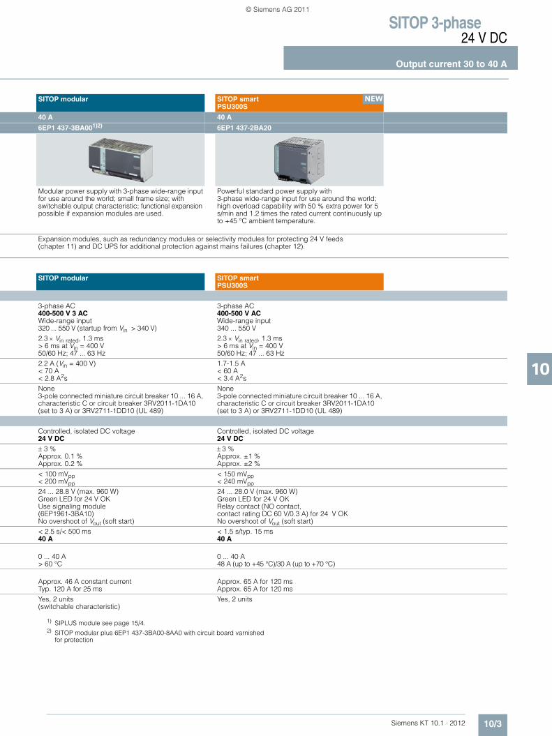
SITOP 3-phase24 V DC
Output current 30 to 40 A
10/3Siemens KT 10.1 · 2012
10
1) SIPLUS module see page 15/4.2) SITOP modular plus 6EP1 437-3BA00-8AA0 with circuit board varnished
for protection
SITOP modular SITOP smartPSU300S
40 A 40 A
6EP1 437-3BA001)2) 6EP1 437-2BA20
Modular power supply with 3-phase wide-range input for use around the world; small frame size; with switchable output characteristic; functional expansion possible if expansion modules are used.
Powerful standard power supply with 3-phase wide-range input for use around the world; high overload capability with 50 % extra power for 5 s/min and 1.2 times the rated current continuously up to +45 °C ambient temperature.
Expansion modules, such as redundancy modules or selectivity modules for protecting 24 V feeds(chapter 11) and DC UPS for additional protection against mains failures (chapter 12).
SITOP modular SITOP smartPSU300S
3-phase AC 3-phase AC400-500 V 3 AC Wide-range input
400-500 V AC Wide-range input
320 ... 550 V (startup from Vin > 340 V) 340 ... 550 V2.3 × Vin rated, 1.3 ms 2.3 × Vin rated, 1.3 ms> 6 ms at Vin = 400 V > 6 ms at Vin = 400 V50/60 Hz; 47 ... 63 Hz 50/60 Hz; 47 ... 63 Hz2.2 A (Vin = 400 V) 1.7-1.5 A< 70 A < 60 A< 2.8 A2s < 3.4 A2sNone None3-pole connected miniature circuit breaker 10 ... 16 A, characteristic C or circuit breaker 3RV2011-1DA10 (set to 3 A) or 3RV2711-1DD10 (UL 489)
3-pole connected miniature circuit breaker 10 ... 16 A, characteristic C or circuit breaker 3RV2011-1DA10 (set to 3 A) or 3RV2711-1DD10 (UL 489)
Controlled, isolated DC voltage Controlled, isolated DC voltage24 V DC 24 V DC ± 3 % ± 3 %Approx. 0.1 % Approx. ±1 %Approx. 0.2 % Approx. ±2 %< 100 mVpp < 150 mVpp< 200 mVpp < 240 mVpp
24 ... 28.8 V (max. 960 W) 24 ... 28.0 V (max. 960 W)Green LED for 24 V OK Green LED for 24 V OKUse signaling module (6EP1961-3BA10)
Relay contact (NO contact, contact rating DC 60 V/0.3 A) for 24 V OK
No overshoot of Vout (soft start) No overshoot of Vout (soft start)< 2.5 s/< 500 ms < 1.5 s/typ. 15 ms40 A 40 A
0 ... 40 A 0 ... 40 A> 60 °C 48 A (up to +45 °C)/30 A (up to +70 °C)
Approx. 46 A constant current Approx. 65 A for 120 msTyp. 120 A for 25 ms Approx. 65 A for 120 msYes, 2 units (switchable characteristic)
Yes, 2 units
NEW
KT10_EN_gesamt.book Seite 3 Mittwoch, 12. Oktober 2011 11:00 11
© Siemens AG 2011
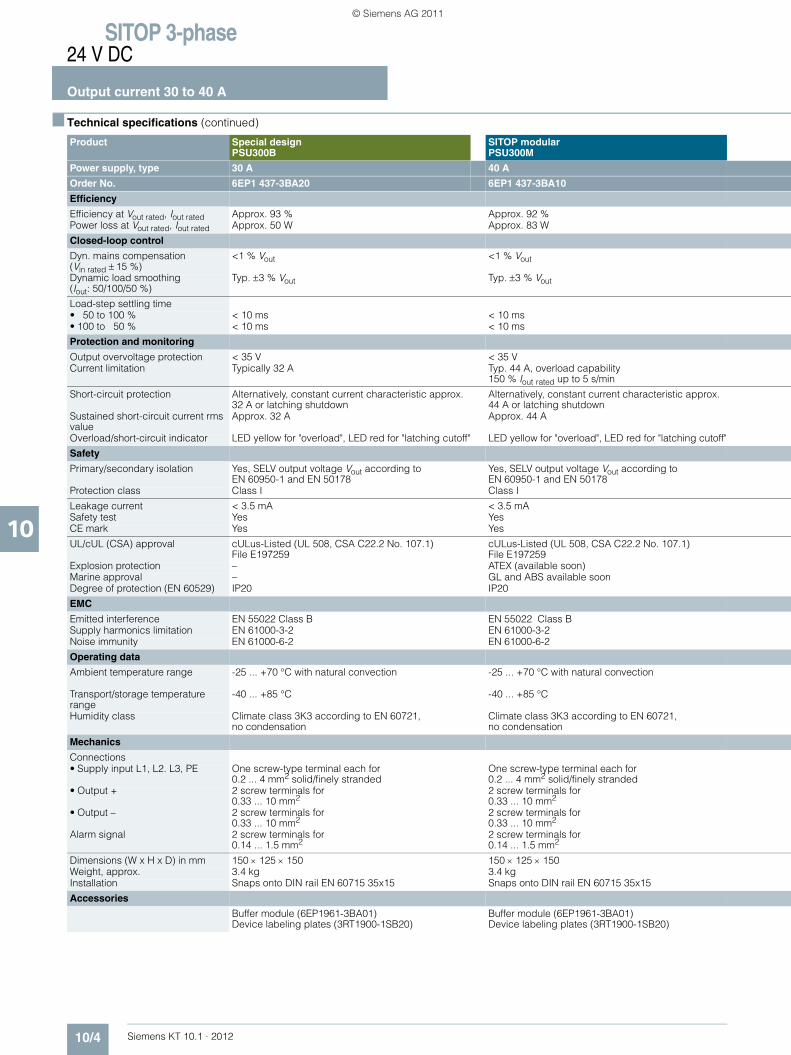
SITOP 3-phase24 V DC
Output current 30 to 40 A
10/4 Siemens KT 10.1 · 2012
10
■ Technical specifications (continued)
Product Special designPSU300B
SITOP modularPSU300M
Power supply, type 30 A 40 A
Order No. 6EP1 437-3BA20 6EP1 437-3BA10
Efficiency
Efficiency at Vout rated, Iout rated Approx. 93 % Approx. 92 %Power loss at Vout rated, Iout rated Approx. 50 W Approx. 83 W
Closed-loop control
Dyn. mains compensation (Vin rated ± 15 %)
<1 % Vout <1 % Vout
Dynamic load smoothing(Iout: 50/100/50 %)
Typ. ±3 % Vout Typ. ±3 % Vout
Load-step settling time• 50 to 100 % < 10 ms < 10 ms• 100 to 50 % < 10 ms < 10 ms
Protection and monitoring
Output overvoltage protection < 35 V < 35 VCurrent limitation Typically 32 A Typ. 44 A, overload capability
150 % Iout rated up to 5 s/min
Short-circuit protection Alternatively, constant current characteristic approx. 32 A or latching shutdown
Alternatively, constant current characteristic approx. 44 A or latching shutdown
Sustained short-circuit current rms value
Approx. 32 A Approx. 44 A
Overload/short-circuit indicator LED yellow for "overload", LED red for "latching cutoff" LED yellow for "overload", LED red for "latching cutoff"
Safety
Primary/secondary isolation Yes, SELV output voltage Vout according to EN 60950-1 and EN 50178
Yes, SELV output voltage Vout according to EN 60950-1 and EN 50178
Protection class Class I Class I
Leakage current < 3.5 mA < 3.5 mASafety test Yes YesCE mark Yes Yes
UL/cUL (CSA) approval cULus-Listed (UL 508, CSA C22.2 No. 107.1) File E197259
cULus-Listed (UL 508, CSA C22.2 No. 107.1) File E197259
Explosion protection – ATEX (available soon)Marine approval – GL and ABS available soonDegree of protection (EN 60529) IP20 IP20
EMC
Emitted interference EN 55022 Class B EN 55022 Class BSupply harmonics limitation EN 61000-3-2 EN 61000-3-2Noise immunity EN 61000-6-2 EN 61000-6-2
Operating data
Ambient temperature range -25 ... +70 °C with natural convection -25 ... +70 °C with natural convection
Transport/storage temperature range
-40 ... +85 °C -40 ... +85 °C
Humidity class Climate class 3K3 according to EN 60721, no condensation
Climate class 3K3 according to EN 60721, no condensation
Mechanics
Connections • Supply input L1, L2. L3, PE One screw-type terminal each for
0.2 ... 4 mm2 solid/finely strandedOne screw-type terminal each for 0.2 ... 4 mm2 solid/finely stranded
• Output + 2 screw terminals for 0.33 ... 10 mm2
2 screw terminals for 0.33 ... 10 mm2
• Output – 2 screw terminals for 0.33 ... 10 mm2
2 screw terminals for 0.33 ... 10 mm2
Alarm signal 2 screw terminals for 0.14 ... 1.5 mm2
2 screw terminals for 0.14 ... 1.5 mm2
Dimensions (W x H x D) in mm 150 × 125 × 150 150 × 125 × 150Weight, approx. 3.4 kg 3.4 kgInstallation Snaps onto DIN rail EN 60715 35x15 Snaps onto DIN rail EN 60715 35x15
Accessories
Buffer module (6EP1961-3BA01) Device labeling plates (3RT1900-1SB20)
Buffer module (6EP1961-3BA01) Device labeling plates (3RT1900-1SB20)
KT10_EN_gesamt.book Seite 4 Mittwoch, 12. Oktober 2011 11:00 11
© Siemens AG 2011
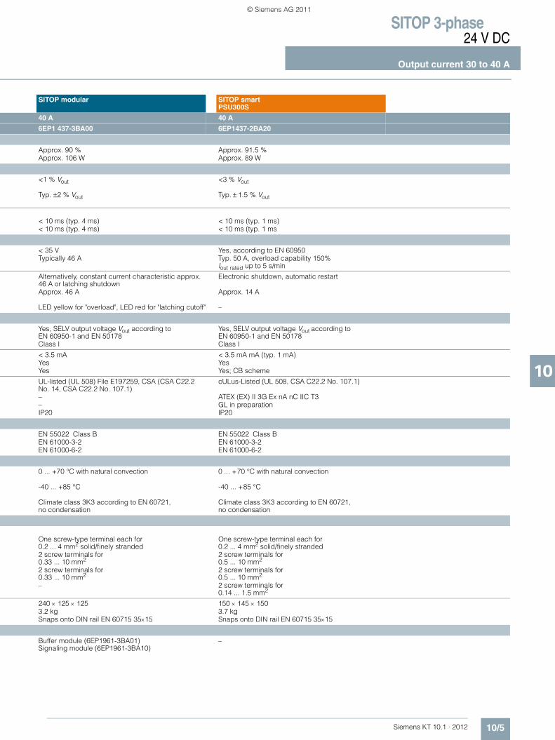
SITOP 3-phase24 V DC
Output current 30 to 40 A
10/5Siemens KT 10.1 · 2012
10
SITOP modular SITOP smartPSU300S
40 A 40 A
6EP1 437-3BA00 6EP1437-2BA20
Approx. 90 % Approx. 91.5 %Approx. 106 W Approx. 89 W
<1 % Vout <3 % Vout
Typ. ±2 % Vout Typ. ± 1.5 % Vout
< 10 ms (typ. 4 ms) < 10 ms (typ. 1 ms)< 10 ms (typ. 4 ms) < 10 ms (typ. 1 ms
< 35 V Yes, according to EN 60950Typically 46 A Typ. 50 A, overload capability 150%
Iout rated up to 5 s/min
Alternatively, constant current characteristic approx. 46 A or latching shutdown
Electronic shutdown, automatic restart
Approx. 46 A Approx. 14 A
LED yellow for "overload", LED red for "latching cutoff" –
Yes, SELV output voltage Vout according to EN 60950-1 and EN 50178
Yes, SELV output voltage Vout according to EN 60950-1 and EN 50178
Class I Class I
< 3.5 mA < 3.5 mA mA (typ. 1 mA)Yes YesYes Yes; CB scheme
UL-listed (UL 508) File E197259, CSA (CSA C22.2 No. 14, CSA C22.2 No. 107.1)
cULus-Listed (UL 508, CSA C22.2 No. 107.1)
– ATEX (EX) II 3G Ex nA nC IIC T3– GL in preparationIP20 IP20
EN 55022 Class B EN 55022 Class B EN 61000-3-2 EN 61000-3-2EN 61000-6-2 EN 61000-6-2
0 ... +70 °C with natural convection 0 ... +70 °C with natural convection
-40 ... +85 °C -40 ... +85 °C
Climate class 3K3 according to EN 60721, no condensation
Climate class 3K3 according to EN 60721, no condensation
One screw-type terminal each for 0.2 ... 4 mm2 solid/finely stranded
One screw-type terminal each for 0.2 ... 4 mm2 solid/finely stranded
2 screw terminals for 0.33 ... 10 mm2
2 screw terminals for 0.5 ... 10 mm2
2 screw terminals for 0.33 ... 10 mm2
2 screw terminals for 0.5 ... 10 mm2
– 2 screw terminals for 0.14 ... 1.5 mm2
240 × 125 × 125 150 × 145 × 1503.2 kg 3.7 kgSnaps onto DIN rail EN 60715 35×15 Snaps onto DIN rail EN 60715 35×15
Buffer module (6EP1961-3BA01) Signaling module (6EP1961-3BA10)
–
KT10_EN_gesamt.book Seite 5 Mittwoch, 12. Oktober 2011 11:00 11
© Siemens AG 2011

SITOP 3-phase24 V DC
Output current 30 to 40 A
10/6 Siemens KT 10.1 · 2012
10
■ Selection and ordering data
■ Further information
Additional information is available in the Internet under:• 2D dimensional drawings, 3D CAD data, circuit diagram
macros: www.siemens.com/sitop-cax
• Operating instructions:www.siemens.de/sitop-manuals
• Find the right product with the SITOP Selection Tool: www.siemens.com/sitop-selection-tool
Product Input Output Order No. Price
Voltage Vin rated Voltage Vout rated Current Iout rated
Special design, PSU300B (Planned delivery date: December 2011)
400-500 V 3 AC
24 V DC 30 A 6EP1 437-3BA20
SITOP modular, PSU300M
400-500 V 3 AC
24 V DC 40 A 6EP1 437-3BA10
SITOP modular
400-500 V 3 AC
24 V DC 40 A 6EP1 437-3BA00
Version with circuit board varnished for protection 6EP1 437-3BA00-8AA0
SITOP smart, PSU300S
400-500 V 3 AC
24 V DC 40 A 6EP1437-2BA20
NEW
NEW
KT10_EN_gesamt.book Seite 6 Mittwoch, 12. Oktober 2011 11:00 11
© Siemens AG 2011

Siemens KT 10.1 · 2012
11
11/2 Signaling module11/2 Redundancy module SITOP PSE202U 11/2 Buffer module11/4 Selectivity module
SITOP PSE200U 4 x 3 A 11/4 Selectivity module
SITOP PSE200U 4 x 10 A 11/4 Diagnostics module
SITOP select 4 x 10 A11/7 Inrush current limiter11/9 Ordering data and additional information
SITOP expansion modules24 V DC
Export regulations AL and ECCNsee page 17/9
KT10_EN_gesamt.book Seite 1 Mittwoch, 12. Oktober 2011 11:00 11
© Siemens AG 2011
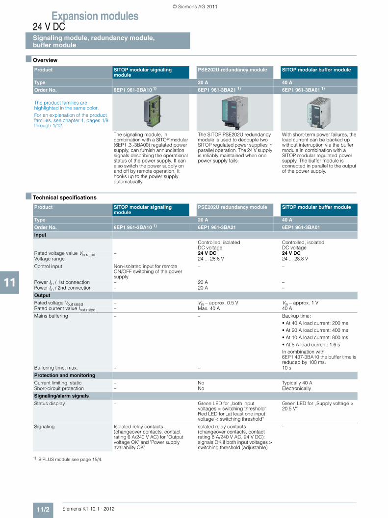
Expansion modules24 V DCSignaling module, redundancy module, buffer module
11/2 Siemens KT 10.1 · 2012
11
■ Overview
■ Technical specifications
1) SIPLUS module see page 15/4.
Product SITOP modular signaling module
PSE202U redundancy module SITOP modular buffer module
Type 20 A 40 A
Order No. 6EP1 961-3BA10 1) 6EP1 961-3BA21 1) 6EP1 961-3BA01 1)
The product families are highlighted in the same color.For an explanation of the product families, see chapter 1, pages 1/8 through 1/12.
The signaling module, in combination with a SITOP modular (6EP1 .3.-3BA00) regulated power supply, can furnish annunciation signals describing the operational status of the power supply. It can also switch the power supply on and off by remote operation. It hooks up to the power supply automatically.
The SITOP PSE202U redundancy module is used to decouple two SITOP regulated power supplies in parallel operation. The 24 V supply is reliably maintained when one power supply fails.
With short-term power failures, the load current can be backed up without interruption via the buffer module in combination with a SITOP modular regulated power supply. The buffer module is connected in parallel to the output of the power supply.
Product SITOP modular signaling module
PSE202U redundancy module SITOP modular buffer module
Type 20 A 40 A
Order No. 6EP1 961-3BA10 1) 6EP1 961-3BA21 6EP1 961-3BA01
Input
Controlled, isolatedDC voltage
Controlled, isolatedDC voltage
Rated voltage value Vin rated – 24 V DC 24 V DC Voltage range – 24 ... 28.8 V 24 ... 28.8 V
Control input Non-isolated input for remote ON/OFF switching of the power supply
– –
Power Iin / 1st connection – 20 A –Power Iin / 2nd connection – 20 A –
Output
Rated voltage Vout rated – Vin – approx. 0.5 V Vin – approx. 1 VRated current value Iout rated – Max. 40 A 40 A
Mains buffering – – Backup time:• At 40 A load current: 200 ms• At 20 A load current: 400 ms• At 10 A load current: 800 ms• At 5 A load current: 1.6 sIn combination with 6EP1 437-3BA10 the buffer time is reduced by 100 ms.
Buffering time, max. – – 10 s
Protection and monitoring
Current limiting, static – No Typically 40 AShort-circuit protection – No Electronically
Signaling/alarm signals
Status display – Green LED for „both input voltages > switching threshold“ Red LED for „at least one input voltage < switching threshold“
Green LED for „Supply voltage > 20.5 V“
Signaling Isolated relay contacts (changeover contacts, contact rating 6 A/240 V AC) for "Output voltage OK" and "Power supply availability OK"
solated relay contacts (changeover contacts, contact rating 8 A/240 V AC, 24 V DC): signals OK if both input voltages > switching threshold (adjustable)
–
KT10_EN_gesamt.book Seite 2 Mittwoch, 12. Oktober 2011 11:00 11
© Siemens AG 2011

Expansion modules24 V DC
Signaling module, redundancy module,buffer module
11/3Siemens KT 10.1 · 2012
11
■ Technical specifications (continued).
Product SITOP modular signaling module
PSE202U redundancy module SITOP modular buffer module
Type 20 A 40 A
Order No. 6EP1 961-3BA10 1) 6EP1 961-3BA21 6EP1 961-3BA01
Safety
Galvanic isolation Yes, safety extra low voltage acc. to EN 60950-1 (relay contacts)
Yes, safety extra low voltage acc. to EN 60950-1 (relay contact)
Yes, SELV acc. to EN 60950-1
Protection class Class I Class II Class I
Safety test Yes Yes YesCE mark Yes Yes Yes
UL/cUL (CSA) approval UL-listed (UL 508) File E197259, CSA (CSA C22.2 No. 14, CSA C22.2 No. 107.1)
cULus-listed (UL 508, CSA C22.2 No. 107.1),File E197259
UL-listed (UL 508) File E197259, CSA (CSA C22.2 No. 14, CSA C22.2 No. 107.1)
Explosion protection – ATEX (EX) II 3G Ex nAC IIC T4cCSAus (CSA E60079, UL 60079), Class I, Div. 2. Groups ABCD
–
Degree of protection (EN 60529) IP20 IP20 IP20
EMC
Emitted interference EN 55022 Class B EN 55022 Class B EN 55022 Class BNoise immunity EN 61000-6-2 EN 61000-6-2 EN 61000-6-2
Operating data
Ambient temperature range 0 ... +60 °C with natural convection
0 ... +60 °C with natural convection
0 ... +60 °C with natural convection
Transport/storage temperature range
-40 ... +85 °C -40 ... +85 °C -40 ... +85 °C
Humidity class Climate class 3K3 according to EN 60721, no condensation
Climate class 3K3 according to EN 60721, no condensation
Climate class 3K3 according to EN 60721, no condensation
Mechanics
Connections Screw terminals for 0.14 ... 2.5 mm2
single-core/finely stranded
Input, output, and ground: one screw terminal each, with0.33 ... 10 mm2. solid/finely stranded;Relay contact: 1 screw terminal each for 0.5 ... 2.5 mm2. single-core/finely stranded
One screw terminal each for + and – for 0.5 ... 10 mm2
single-core/finely stranded
Dimensions (W × H × D) in mm 26 × 125 × 116 70 × 125 × 125 70 × 125 × 125Weight, approx. 0.15 kg 0.5 kg 1.2 kgInstallation Can be snapped directly on the
side of the basic unit (6EP1 .3.-3BA00)
Snaps onto DIN rail EN 60715 35x7.5/15
Snaps onto DIN rail EN 60715 35x7.5/15
KT10_EN_gesamt.book Seite 3 Mittwoch, 12. Oktober 2011 11:00 11
© Siemens AG 2011

Expansion modules24 V DCPSE200U selectivity module,SITOP select diagnostics module
11/4 Siemens KT 10.1 · 2012
11
■ Overview
■ Technical specifications
1) SITOP select is not designed for operation with DC UPS module 40 A (6EP1 931-2FC21/-2FC42).
Product PSE200U selectivity module SITOP select diagnostics module
Type 4 x 3 A 4 x 10 A 4 x 10 A
Order No. 6EP1 961-2BA11 6EP1 961-2BA21 6EP1 961-2BA00
The selectivity module is used in conjunction with 24 V power supplies to distribute the load current over several current circuits and to monitor the individual currents. Faults in individual circuits caused by overload or short-circuit are detected and selectively switched off so that further load current paths remain unaffected by the fault. This achieves fast fault diagnostics and minimizes standstill times.
The selectivity module is used in conjunction with 24 V power supplies to distribute the load current over several current circuits and to monitor the individual currents. Faults in individual circuits caused by overload or short-circuit are detected and selectively switched off so that further load current paths remain unaffected by the fault. This achieves fast fault diagnostics and minimizes standstill times.
The diagnostics module is used in conjunction with 24 V power supplies to distribute the load current over several current circuits and to monitor the individual currents. Faults in individual circuits caused by overload or short-circuit are detected and selectively switched off so that further load current paths remain unaffected by the fault. This achieves fast fault diagnostics and minimizes standstill times.
Product PSE200U selectivity module SITOP select diagnostics module
Type 4 x 3 A 4 x 10 A 4 x 10 A
Order No. 6EP1 961-2BA11 6EP1 961-2BA21 6EP1 961-2BA00
Input
Controlled DC voltage Controlled DC voltage Controlled DC voltage 1)
Rated voltage value Vin rated 24 V DC 24 V DC 24 V DCVoltage range 22 ... 30 V 22 ... 30 V 22 ... 30 V
Overvoltage resistance 35 V 35 V 35 V; 100 msRated current Iin rated 12 A 40 A 40 A
Output
Controlled DC voltage Controlled DC voltage Controlled DC voltage Rated voltage Vout rated Vin – approx. 0.2 V Vin – approx. 0.2 V Vin – approx. 0.3 V Total tolerance In accordance with the supplying
input voltageIn accordance with the supplying input voltage
In accordance with the supplying input voltage
Number of output channels 4 4 4
Rated current value Iout rated 3 A per channel 10 A per channel 10 A per channelAdjustment range 0.5 ... 3 A per channel via
potentiometer3 ... 10 A per channel via potentiometer
2 ... 10 A per channel via potentiometer
Parallel switching of several channels
Not permitted Not permitted Not permitted
Channel connection Simultaneous connection of all channels after power up of the supply voltage > 20 V, delay time of 25 ms, 100 ms or adjustable "load optimized" via DIP switch for sequential connection
Simultaneous connection of all channels after power up of the supply voltage > 20 V, delay time of 25 ms, 100 ms or adjustable "load optimized" via DIP switch for sequential connection
Simultaneous connection of all channels after power up of the supply voltage,delay time of 24 ms or 100 ms programmable for sequential connection
Efficiency
Efficiency at Vout rated, Iout rated Approx. 97 % Approx. 97 % (typ. 99 %) Approx. 97 %Power loss at Vout rated, Iout rated Approx. 9 W Approx. 30 W (typ. 10 W) Approx. 30 W
Switch-off characteristic per channel
Overcurrent switch-off Iout = 1.0 ... 1.3 × set value, switch-off after approx. 5 s
Iout = 1.0 ... 1.3 × set value, switch-off after approx. 5 s
Iout = 1.0 ... 1.3 × set value, switch-off after approx. 5 s
Current limitation Ia = 1.3 × set value, switch-off not before typ. 100 ms
Ia = 1.3 × set value, switch-off not before typ. 100 ms
Iout = 1.35 × set value, switch-off after approx. 50 ...100 ms
Immediate switch-off Iout > set value and Vin < 20 V, switch-off after approx. 0.5 ms
Iout > set value and Vin < 20 V, switch-off after approx. 0.5 ms
Iout > set value and Vin < 20 V, switch-off after approx. 0.5 ms
Residual current at switch-off – – Typ. 20 mAReset Using keys for each channel Using keys for each channel Using keys on the moduleRemote reset Non-isolated 24 V input (signal
level "high" at >15 V)Non-isolated 24 V input (signal level "high" at >15 V)
–
KT10_EN_gesamt.book Seite 4 Mittwoch, 12. Oktober 2011 11:00 11
© Siemens AG 2011

Expansion modules24 V DC
PSE200U selectivity module,SITOP select diagnostics module
11/5Siemens KT 10.1 · 2012
11
■ Technical specifications (continued).
Product PSE200U selectivity module SITOP select diagnostics module
Type 4 x 3 A 4 x 10 A 4 x 10 A
Order No. 6EP1 961-2BA11 6EP1 961-2BA21 6EP1 961-2BA00
Protection and monitoring
Device/line protection Internal fuse 5 A per channel (not accessible)
Internal fuse 15 A per channel (not accessible)
FKS blade-type fuse per channel (equipped with 15 A fuse in as-delivered state)
Status displays Three-color LED per channel:• Green LED for "Output
switched through" • Yellow LED for "Output turned off
manually"• Red LED for "Output turned off
because of overcurrent"
Three-color LED per channel:• Green LED for "Output
switched through" • Yellow LED for "Output turned off
manually" • Red LED for "Output turned off
because of overcurrent"
Two-color LED per channel:• Green LED for "Output
switched through"• Red LED for "Output turned off
because of overcurrent"
Signaling Common signal contact (changeover contact, rating 0.1 A/24 V DC)
Common signal contact (changeover contact, rating 0.1 A/24 V DC)
Common signal contact (NO contact, rating 0.5 A/24 V DC)
Safety
In accordance with EN 60950-1 and EN 50178
In accordance with EN 60950-1 and EN 50178
In accordance with EN 60950-1 and EN 50178
Protection class Class III Class III Class IIIDegree of protection (EN 60529) IP20 IP20 IP20CE mark Yes Yes YesUL/cUL (CSA) approval UL-recognized (UL 2367) File
E328600; cURus (UL 508, CSA22.2 No. 107.1), File E197259
UL-recognized (UL 2367) File E328600; cURus (UL 508, CSA22.2 No. 107.1), File E197259
UL-Recognized (UL 2367)File E328600; cURus (UL 508,CSA C22.2 No. 107.1) File E197259; cURus (UL 60950, CSA C22.2 No. 60950), File E151273
Explosion protection ATEX (EX) II 3G Ex nAC II T4; cCSAus (CSA E60079, UL 60079), Class I, Div. 2. Gr ABCD T4
ATEX (EX) II 3G Ex nAC II T4; cCSAus (CSA E60079, UL 60079), Class I, Div. 2. Gr ABCD T4
ATEX (EX) II 3G Ex nAC IIC T4 U; cCSAus (CSA C22.2 No. 60079,UL 60079), Class I, Div. 2. Gr ABCD T4
EMC
Emitted interference EN 55022 Class B EN 55022 Class B EN 55022 Class BNoise immunity EN 61000-6-2 EN 61000-6-2 EN 61000-6-2
Operating data
Permitted ambient temperature 0 ... +60 °C with natural convection
0 ... +60 °C with natural convection
0 ... +60 °C with natural convection
Transport/storage temperature range
-40 ... +85 °C -40 ... +85 °C -40 ... +85 °C
Humidity class Climate class 3K3 according to EN 60721, no condensation
Climate class 3K3 according to EN 60721, no condensation
Climate class 3K3 according to EN 60721, no condensation
Mechanics
Connections• Input +24 V 2 screw terminals
for 0.5 ... 10 mm22 screw terminals for 0.5 ... 10 mm2
2 screw terminals for 0.33 ... 10 mm2
• Input 0 V 2 screw terminals for 0.5 ... 4 mm2
2 screw terminals for 0.5 ... 4 mm2
2 screw terminals for 0.22 ... 4 mm2
• Output 1 ... 4 1 screw terminal each for 0.5 ... 4 mm2
1 screw terminal each for 0.5 ... 4 mm2
1 screw terminal each for 0.22 ... 4 mm2
• Signaling contact 3 screw terminals for 0.5 ... 4 mm2
3 screw terminals for 0.5 ... 4 mm2
2 screw terminals for 0.22 ... 4 mm2
• Remote reset 1 screw terminal for 0.5 ... 4 mm2
1 screw terminal for 0.5 ... 4 mm2
–
Dimensions (W × H × D) in mm 72 × 80 × 72 72 × 80 × 72 72 × 90 × 90Weight, approx. 0.2 kg 0.2 kg 0.4 kgInstallation Snaps onto DIN rail EN 60715
35x7.5/15Snaps onto DIN rail EN 60715 35x7.5/15
Snaps onto DIN rail EN 60715 35x7.5/15
KT10_EN_gesamt.book Seite 5 Mittwoch, 12. Oktober 2011 11:00 11
© Siemens AG 2011

Expansion modules24 V DCPSE200U selectivity module,SITOP select diagnostics module
11/6 Siemens KT 10.1 · 2012
11
■ Characteristics
Switch-off characteristic
■ Circuit diagrams
Switching principle SITOP select
Switching principle SITOP PSE200U
0 20 40 60 80 100 120 140%
Load current
Rel
ease
tim
e
100.0
10.0
1.0
0.1
0.0
5.0 s
0.10 s
rated
G_K
T01
_EN
_000
62
s
-
Reset
24V
G_K
T01_
EN
_000
63a
Power supply
Control Logics
Floatingsignalingcontact Load 1 Load 2 Load 3 Load 4
SITOP select+ 24V
Power supply, e.g. SITOP
SITOP PSE200 U
Remote reset(24 V DC)
Floating signaling contact
Control Logics
Load 1
Load 2
Load 3
Load 4
G_KT01_EN_00378
KT10_EN_gesamt.book Seite 6 Mittwoch, 12. Oktober 2011 11:00 11
© Siemens AG 2011

Expansion modules100 - 480 V AC
SITOP inrush current limiter
11/7Siemens KT 10.1 · 2012
11
■ Overview
■ Technical specifications
Product SITOP inrush current limiter
Order No. 6EP1 967-2AA00
The SITOP inrush current limiter module is used to reliably reduce the starting currents that are caused, for example, by capacitors or with pulse-controlled power supplies by the rectifier circuit on the input side with capacitor chargingIn 1-phase AC networks, it is supplied with rated voltages of 100 V, 120 V or 230 V and in 2-phase and 3-phase AC networks with 208 V to 480 V on the line side upstream of capacitors and power supplies and it limits the inrush current temperature-independently up to e. g. < 10 A at 230 V. In static operation the limit resistance is bypassed after approx. 120 ms and the resulting power loss is reduced.
Product SITOP inrush current limiter
Order No. 6EP1 967-2AA00
Input
AC voltage 1-phase, 2-phase, 50/60 Hz
Rated voltage value Vin rated 100 ... 480 V ACVoltage range 85 ... 575 V
Overvoltage resistance –Input current Iin rated –
Output
Rated voltage Vout rated In accordance with the supply voltage
Rated current value Iout rated Max. 10 AMains buffering –Buffering time, max. –Parallel switching for enhanced performance
No
Protection and monitoring
Current limiting, static –Short-circuit protection Must be ensured with an upstream
protective device
Signaling/alarm signals
Status display Green LEDAlarm signals –
Product SITOP inrush current limiter
Order No. 6EP1 967-2AA00
Safety
In accordance with EN 60950-1 and EN 50178
Galvanic isolation NoProtection class Class II
CE mark YesUL/cUL (CSA) approval Yes, cULus-listed (UL 508, CSA
C22.2 No. 107.1), File E197259Degree of protection (EN 60529) IP20
EMC
Emitted interference EN 61000-6-3Noise immunity EN 61000-6-2
Operating data
Permitted ambient temperature 0 ... +60 °C with natural convection
Transport/storage temperature range
-40 ... +85 °C
Humidity class Climate class 3K3 according to EN 60721, no condensation
Mechanics
Connections Input and output (L1, N): One screw terminal each for0.2 ... 2.5 mm2 single-core/finely stranded;
Dimensions (W × H × D) in mm 22.5 × 80 × 91Weight, approx. 0.12 kgInstallation Snaps onto DIN rail EN 60715
35x7.5/15
KT10_EN_gesamt.book Seite 7 Mittwoch, 12. Oktober 2011 11:00 11
© Siemens AG 2011
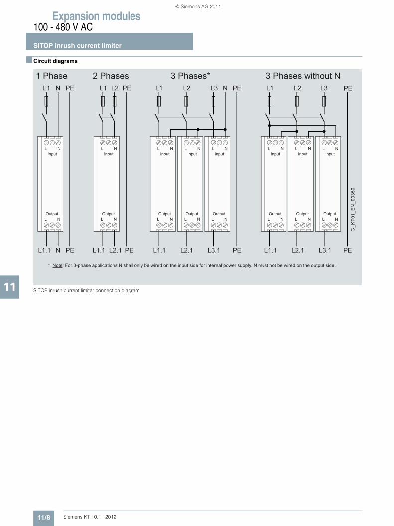
Expansion modules100 - 480 V AC
SITOP inrush current limiter
11/8 Siemens KT 10.1 · 2012
11
■ Circuit diagrams
SITOP inrush current limiter connection diagram
1 Phase 2 Phases 3 Phases* 3 Phases without
G_K
T01_
EN
_003
50
* Note: For 3-phase applications N shall only be wired on the input side for internal power supply. N must not be wired on the output side.
PEL1.1 N PEL1.1 L2.1 PEL1.1 L2.1 L3.1 PEL1.1 L2.1 L3.1
L N
L N
Input
Output
L N
L N
Input
Output
L N
L N
Input
Output
L N
L N
Input
Output
L N
L N
Input
Output
L N
L N
Input
Output
L N
L N
Input
Output
L N
L N
Input
Output
NPEPEPE NN L3L2L2 L1L1L1 L3L2L1 PE
KT10_EN_gesamt.book Seite 8 Mittwoch, 12. Oktober 2011 11:00 11
© Siemens AG 2011
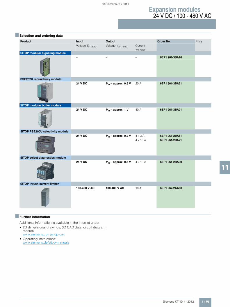
Expansion modules24 V DC / 100 - 480 V AC
11/9Siemens KT 10.1 · 2012
11
■ Selection and ordering data
■ Further information
Additional information is available in the Internet under:• 2D dimensional drawings, 3D CAD data, circuit diagram
macros: www.siemens.com/sitop-cax
• Operating instructions:www.siemens.de/sitop-manuals
Product Input Output Order No. PriceVoltage Vin rated Voltage Vout rated Current
Iout rated
SITOP modular signaling module – – – 6EP1 961-3BA10
PSE202U redundancy module24 V DC Vin – approx. 0.5 V 20 A 6EP1 961-3BA21
SITOP modular buffer module 24 V DC Vin – approx. 1 V 40 A 6EP1 961-3BA01
SITOP PSE200U selectivity module 24 V DC Vin – approx. 0.2 V 4 x 3 A 6EP1 961-2BA11
4 x 10 A 6EP1 961-2BA21
SITOP select diagnostics module 24 V DC Vin – approx. 0.3 V 4 x 10 A 6EP1 961-2BA00
SITOP inrush current limiter100-480 V AC 100-480 V AC 10 A 6EP1 967-2AA00
KT10_EN_gesamt.book Seite 9 Mittwoch, 12. Oktober 2011 11:00 11
© Siemens AG 2011

Expansion modules
Notes
11/10 Siemens KT 10.1 · 2012
11
■
KT10_EN_gesamt.book Seite 10 Mittwoch, 12. Oktober 2011 11:00 11
© Siemens AG 2011

Siemens KT 10.1 · 2012
1212/2 Overview
12/4 DC UPS software
12/5 DC UPS with capacitors12/5 Overview12/6 SITOP UPS500S 15 A12/6 SITOP UPS500P 7 A12/9 SITOP UPS501S
12/10 DC UPS with battery modules12/10 Overview12/14 DC UPS module 6 A12/14 DC UPS module 15 A12/14 DC UPS module 40 A12/18 Battery module 1.2 Ah12/18 Battery module 2.5 Ah12/18 Battery module 3.2 Ah12/19 Battery module 7 Ah12/19 Battery module 12 Ah
12/22 Ordering data and additional information
SITOP Uninterruptible power supplies UPS 24 V DC
Export regulations AL and ECCNsee page 17/9
KT10_EN_gesamt.book Seite 1 Mittwoch, 12. Oktober 2011 11:00 11
© Siemens AG 2011
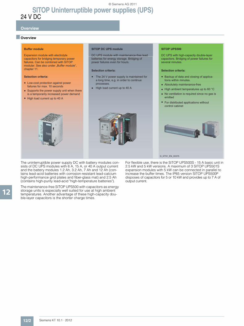
SITOP Uninterruptible power supplies (UPS)24 V DC
Overview
12/2 Siemens KT 10.1 · 2012
12
■ Overview
The uninterruptible power supply DC with battery modules con-sists of DC UPS modules with 6 A, 15 A, or 40 A output current and the battery modules 1.2 Ah, 3.2 Ah, 7 Ah and 12 Ah (con-tains lead-acid batteries with corrosion-resistant lead-calcium high-performance grid plates and fiber-glass mat) and 2.5 Ah (contains high-purity lead-acid "high-temperature batteries").
The maintenance-free SITOP UPS500 with capacitors as energy storage units is especially well suited for use at high ambient temperatures. Another advantage of these high-capacity dou-ble-layer capacitors is the shorter charge times.
For flexible use, there is the SITOP UPS500S - 15 A basic unit in 2.5 kW and 5 kW versions. A maximum of 3 SITOP UPS501S expansion modules with 5 kW can be connected in parallel to increase the buffer times. The IP65 version SITOP UPS500P disposes of capacitors for 5 or 10 kW and provides up to 7 A of output current.
High load current up to 40 ANo ventilation is required since no gas is emitted
For distributed applications without control cabinet
Supports the power supply unit when there is a temporarily increased power demand
High ambient temperatures up to 60 °CAbsolutely maintenance-free Low-cost protection against power
failures for max. 10 seconds
The 24 V power supply is maintained for a long time, e.g. in order to continue processes.
Backup of data and closing of applica-tions within minutes.
Selection criteria:
Expansion module with electrolyte capacitors for bridging temporary power failures. Can be combined with SITOP modular. See also under „Buffer module“, chapter 11.
DC UPS module with maintenance-free lead batteries for energy storage. Bridging of power failures even for hours.
DC UPS with high-capacity double-layer capacitors. Bridging of power failures for several minutes.
Buffer module
Selection criteria:
SITOP UPS500
High load current up to 40 A
Selection criteria:
SITOP DC UPS module
G_KT01_EN_00375
KT10_EN_gesamt.book Seite 2 Mittwoch, 12. Oktober 2011 11:00 11
© Siemens AG 2011
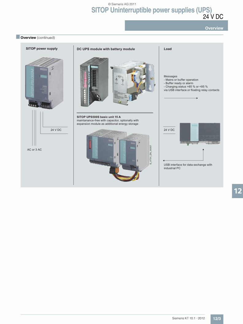
SITOP Uninterruptible power supplies (UPS)24 V DC
Overview
12/3Siemens KT 10.1 · 2012
12
■ Overview (continued)
G_K
T01_
EN
_003
57
SITOP power supply
24 V DC 24 V DC
DC UPS module with battery module
Messages- Mains or buffer operation- Buffer ready or alarm - Charging status >85 % or <85 %via USB interface or floating relay contacts
USB interface for data exchange with industrial PC
SITOP UPS500S basic unit 15 Amaintanance-free with capacitor, optionally with expansion module as additional energy storage
Load
AC or 3 AC
KT10_EN_gesamt.book Seite 3 Mittwoch, 12. Oktober 2011 11:00 11
© Siemens AG 2011
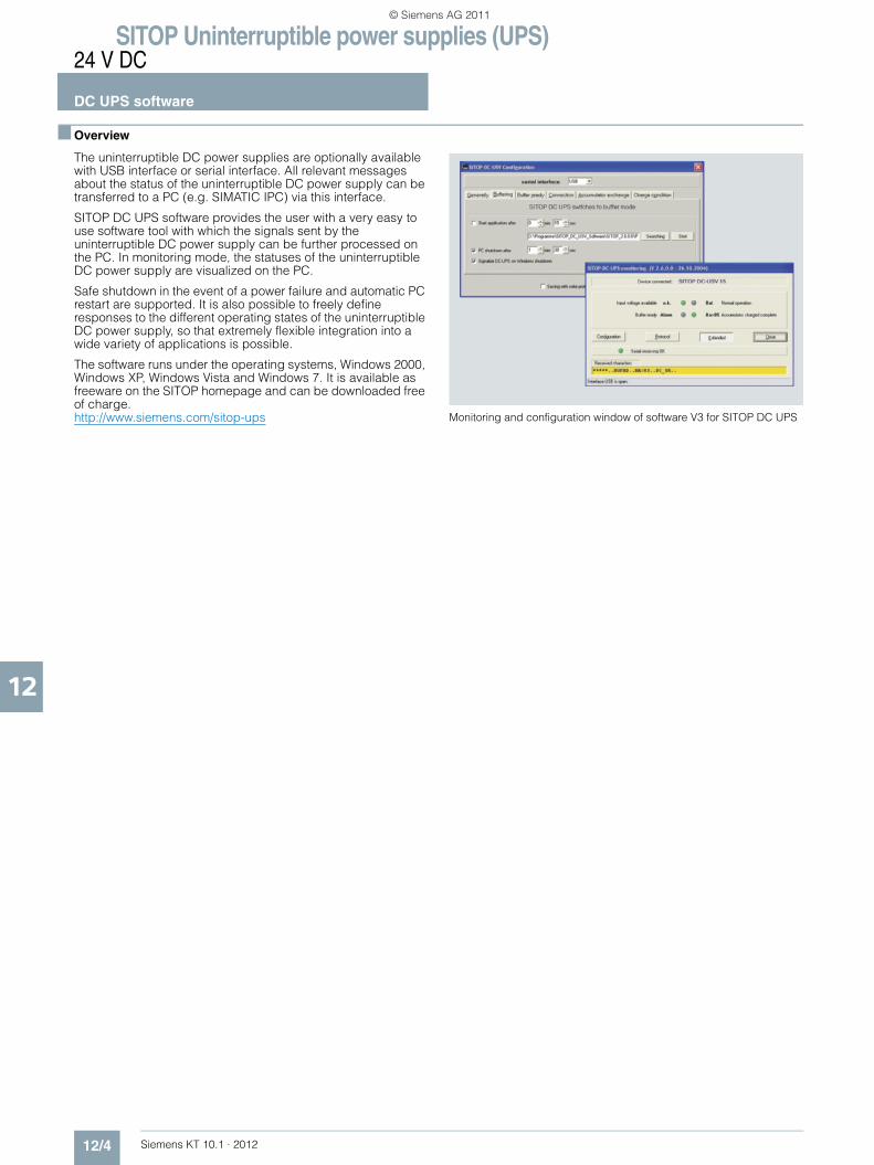
SITOP Uninterruptible power supplies (UPS)24 V DC
DC UPS software
12/4 Siemens KT 10.1 · 2012
12
■ Overview
The uninterruptible DC power supplies are optionally available with USB interface or serial interface. All relevant messages about the status of the uninterruptible DC power supply can be transferred to a PC (e.g. SIMATIC IPC) via this interface.
SITOP DC UPS software provides the user with a very easy to use software tool with which the signals sent by the uninterruptible DC power supply can be further processed on the PC. In monitoring mode, the statuses of the uninterruptible DC power supply are visualized on the PC.
Safe shutdown in the event of a power failure and automatic PC restart are supported. It is also possible to freely define responses to the different operating states of the uninterruptible DC power supply, so that extremely flexible integration into a wide variety of applications is possible.
The software runs under the operating systems, Windows 2000, Windows XP, Windows Vista and Windows 7. It is available as freeware on the SITOP homepage and can be downloaded free of charge.http://www.siemens.com/sitop-ups Monitoring and configuration window of software V3 for SITOP DC UPS
KT10_EN_gesamt.book Seite 4 Mittwoch, 12. Oktober 2011 11:00 11
© Siemens AG 2011

SITOP Uninterruptible power supplies (UPS)24 V DC
DC UPS with capacitorsOverview
12/5Siemens KT 10.1 · 2012
12
■ Overview
Uninterruptible power supplies normally store the electrical en-ergy in lead-acid batteries. Temperatures such as those preva-lent in control cabinets considerably shorten the service life of the battery, however, and the batteries must be replaced on a regular basis – annually at an ambient temperature of 40 °C, for example. The innovative SITOP UPS500, however, is based on absolutely maintenance-free capacitors with a long service life. Even at temperatures of 50 °C they still have more than 80 % of their capacity after 8 years, so there is no need to replace the en-
ergy stores. Because the capacitors do not emit any gas, the control cabinet does not have to be ventilated.
Another advantage is the significantly shorter charging times of the double-layer capacitors, which ensure that the buffer is ready very quickly after loss of power.
The IP65 version SITOP UPS500P has capacitors for 5 or 10 kW and provides up to 7 A of output current. The oblong metal enclosure is also suitable for installing on support arm systems.
Selection table SITOP UPS500 (optional with SITOP UPS501S expansion module) and mains buffering times
Important information for selecting the energy storage units:
When the mains buffering times were determined, the discharge period of new or non-aged, completely charged capacitors was used as a basis. At a continuous ambient temperature of +50 °C, a loss of capacity of approx. 20% must be considered after a service life of 8 years.
Buffering and charging times
SITOP UPS500S/501S configurations UPS500P
Basic unit 2.5 kW 5 kW 2.5 kW 5 kW 2.5 kW 5 kW 2.5 kW 5 kW 5 kW 10 kW
Expansion modules
– – 1 × 5 KWs 1 × 5 KWs 2 × 5 KWs 2 × 5 KWs 3 × 5 KWs 3 × 5 KWs – –
Total energy 2.5 kW 5 kW 7.5 kW 10 kW 12.5 kW 15 kW 17.5 kW 20 kW 5 kW 10 kW
Load current Buffer times
0.5 A 134 s 236 s 390 s 478 s 632 s 748 s 851 s 1007 s 284 s 647 s
0.8 A 90 s 167 s 266 s 346 s 440 s 527 s 580 s 706 s 190 s 435 s
1 A 75 s 138 s 219 s 296 s 365 s 414 s 490 s 572 s 153 s 351 s
2 A 38 s 76 s 122 s 156 s 203 s 230 s 265 s 306 s 80 s 152 s
3 A 26 s 52 s 82 s 106 s 136 s 159 s 186 s 213 s 53 s 108 s
4 A 19 s 39 s 61 s 81 s 101 s 120 s 139 s 160 s 40 s 84 s
5 A 15 s 31 s 49 s 65 s 81 s 95 s 111 s 130 s 30 s 68 s
6 A 12 s 26 s 40 s 55 s 67 s 80 s 94 s 106 s 25 s 57 s
7 A 10 s 21 s 34 s 47 s 58 s 69 s 81 s 82 s 21 s 49 s
8 A 8 s 18 s 29 s 40 s 50 s 59 s 69 s 79 s – –
10 A 6 s 15 s 23 s 32 s 39 s 47 s 54 s 62 s – –
12 A 4 s 12 s 19 s 26 s 32 s 38 s 44 s 52 s – –
15 A 3 s 9 s 14 s 20 s 25 s 30 s 35 s 40 s – –
Charging current
Charging times
2 A 54 s 120 s 158 s 223 s 263 s 318 s 355 s 417 s 130 s 360 s
1 A 110 s 205 s 311 s 425 s 503 s 625 s 695 s 816 s - -
KT10_EN_gesamt.book Seite 5 Mittwoch, 12. Oktober 2011 11:00 11
© Siemens AG 2011

SITOP Uninterruptible power supplies (UPS)24 V DCDC UPS with capacitorsSITOP UPS500
12/6 Siemens KT 10.1 · 2012
12
■ Overview
■ Technical specifications
1) All SITOP 24 V DC power supplies are permissible without restriction.
Product SITOP UPS500S 15 A SITOP UPS500P 7 A
Power supply, type Basic unit 15 A Basic unit 7 A, IP65
Order No. 6EP1 933-2EC41 (with USB interface and 2.5 kWs)6EP1 933-2EC51 (with USB interface and 5 kWs)
6EP1 933-2NC01 (with USB interface and 5 kWs)6EP1 933-2NC11 (with USB interface and 10 kWs)
• Compact design, only 120 mm wide
• Two versions with integrated energy storage units: 2.5 kWs or 5 kWs
• Can be expanded easily using a user-friendly plug-in system with the expansion module 5 kWs
• Absolutely uninterruptible bridging of power failures, as soon as the DC UPS input voltage falls below the value set by the DIP switches
• High level of safety and availability through monitoring of operational readiness, and monitoring of the capacitor charge (message "> 85 % charged")
• Support for automatic warm restart of industrial PCs through selectable shutdown characteristics
• With USB interface
• Compact design, degree of protection IP65• For distributed use,
e.g. on support arms • Integrated energy storage:
5 kW or 10 kW • Ambient temperature range for operation: 0 to +55
°C• High degree of efficiency 96.9 % or or low power
loss, approx. 6 W with 7 A load current• USB interface • Indication of the operating states "normal operation",
"buffer mode", alarm message "Buffer not ready" and capacitor charge > 85 %
Product SITOP UPS500S 15 A SITOP UPS500P 7 A
Input L+/M in normal operation
Controlled DC voltage Controlled DC voltageRated voltage Vin rated
1) 24 V DC 24 V DCVoltage range 22 ... 29 V 22.5 ... 29 V
Connection threshold for buffering 22.5 V DC ± 0.1 V (factory setting), adjustable in the range 22 ... 25.5 V DC (in 0.5 V increments)
22.5 V DC ±0.1 V
Rated current Iin rated 15.2 A + approx. 2.3 A with empty energy storage (capacitor)
7 A + approx. 2 A with empty energy storage (capacitor)
Mains buffering
Mains buffering or buffering times without add-on modules
6EP1 933-2EC41: 15 A for 3 s or 10 A for 6 s or 5 A for 15 s or 2 A for 38 s6EP1 933-2EC51: 15 A for 9 s or 10 A for 15 sor 5 A for 31 s or 2 A for 76 s
7 A for 49 s or 5 A for 68 s or 3 A for 108 s or 1 A for 351 s
Mains buffering or buffering times with expansion modules
For longer buffering times, see table not applicable
On/off control circuit External isolated NO contact required (loading max. 15 V DC/max. 10 mA). Buffering is terminated by disconnecting the control circuit.
not applicable
Methods of setting the buffering time
Adjustable using DIP switches to a maximum buffering time up to forced shutdown at approx. 7 V internal capacitor voltage (output remains constant at 24 V up to that point) or to a time limit of 5 ... 315 s (in 10 s increments) if the energy content is sufficient for the required current
not applicable
Interruption Adjustable with DIP switch, either:• Interruption of the output voltage despite returning
input voltage for 5 s following expiry of set buffering time to support automatic restarting of industrial PCs
Or • No forced interruption at the end of the set buffer
time
not applicable
KT10_EN_gesamt.book Seite 6 Mittwoch, 12. Oktober 2011 11:00 11
© Siemens AG 2011

SITOP Uninterruptible power supplies (UPS)24 V DC
DC UPS with capacitorsSITOP UPS500
12/7Siemens KT 10.1 · 2012
12
■ Technical specifications (continued).
Product SITOP UPS500S 15 A SITOP UPS500P 7 A
Power supply, type Basic unit 15 A Basic unit 7 A, IP65
Order No. 6EP1 933-2EC41 (with USB interface and 2.5 kWs)6EP1 933-2EC51 (with USB interface and 5 kWs)
6EP1 933-2NC01 (with USB interface and 5 kWs)6EP1 933-2NC11 (with USB interface and 10 kWs)
Output L+/M in normal operation
Rated voltage Vout rated 24 V DC (controlled) 24 V DC (controlled)
Voltage range 23.3 ... 24.7 V DC or 24 V DC ±3% 23.3 ... 24.7 V DC or 24 V DC ±3%
Startup delay Approx. 600 ms Approx. 600 ms
Voltage rise Approx. 25 ms Approx. 25 ms
Output current Iout 0 ... 15 A 0 ... 7 A
Dynamic current with overload Electronic current limitation to typically 25 A for approx. 200 ms, then electronic shutdown of the output with automatic restart attempts (approx. 20 s intervals between restart attempts).
Electronic shutdown at typ. 30 A, automatic restart after 20 s
Dynamic current with short-circuit Electronic current limitation to typically 25 A for approx. 110 ms, then electronic shutdown of the output with automatic restart attempts (approx. 20 s intervals between restart attempts).
Electronic shutdown at typ. 30 A, automatic restart after 20 s
Output L+/M with buffer mode
Rated voltage Vout rated 24 V DC 24 V DC
Approximate voltage range 23.3 ... 24.7 V DC or 24 V DC ±3% 23.3 ... 24.7 V DC or 24 V DC ±3%
Output current Iout 0 ... 15 A 0 ... 7 A
Dynamic current with overload Electronic current limitation to typically 25 A for approx. 200 ms, then electronic shutdown of the output (restarts after normal operation is resumed).
Electronic shutdown at typ. 30 A, automatic restart after 20 s
Dynamic current with short-circuit Electronic current limitation to typically 25 A for approx. 110 ms, then electronic shutdown of the output (restarts after normal operation is resumed).
Electronic shutdown at typ. 30 A, automatic restart after 20 s
Charging current Approx. 1 A (factory setting), adjustable to 1 A or 2 A (charging is carried out with closed and open on/off circuit).
2 A set permanently
Charge time after a discharge 6EP1 933-2EC41: 110 s with 1 A, 54 s with 2 A6EP1 933-2EC51: 205 s with 1 A, 120 s with 2 A
approx. 300 s
Charging time with add-on modules For longer charging times, see table not applicable
Efficiency/heat loss
At Vout rated, Iout rated approx. 97.5 % / 9 W 96.5 % / 5.2 W
Protection and monitoring
Reverse polarity protection against polarity reversal on input voltage against polarity reversal on input voltage
Overload protection Electronic shutdown of the output in accordance with "dynamic current with overload" in normal operation (automatic restart attempts) or in buffer mode (restart following return to normal operation).
Electronic shutdown of the output in accordance with "dynamic current with overload" in normal operation (automatic restart attempts) or in buffer mode (restart following return to normal operation).With thermal overload protection
Short-circuit protection Electronic shutdown of the output in accordance with "dynamic current with overload" in normal operation (automatic restart attempts) or in buffer mode (restart following return to normal operation), built-in (unaccessible) fuse rated at 20 A.
Electronic shutdown of the output in accordance with "dynamic current with overload" in normal operation (automatic restart attempts) or in buffer mode (restart following return to normal operation).With thermal overload protection
KT10_EN_gesamt.book Seite 7 Mittwoch, 12. Oktober 2011 11:00 11
© Siemens AG 2011

SITOP Uninterruptible power supplies (UPS)24 V DCDC UPS with capacitorsSITOP UPS500
12/8 Siemens KT 10.1 · 2012
12
■ Technical specifications (continued).
1) 85 % with regard to residual capacity still available depending on aging. The original capacity (= capacity when new) reduces by only approx. 20 % within 8 years of operation even at a high ambient temperature of the device of +50 °C, for example, so that 80 % residual capacity still remains. The backup times also reduce by approximately 20 % in 8 years (at +50 °C) with small currents (up to approximately 5 A), and by approximately 30 % with high load currents (over 10 A).Note: The lower the ambient temperature, the smaller the capacity reduction (approximately one half per 10 °C lower ambient temperature, that is at +40 °C, for example, only 10 % capacity reduction in 8 years).
2) Permissible contact rating: 60 V DC/1 A or 30 V AC/1 A.
Product SITOP UPS500S 15 A SITOP UPS500P 7 A
Power supply, type Basic unit 15 A Basic unit 7 A, IP65
Order No. 6EP1 933-2EC41 (with USB interface and 2.5 kWs)6EP1 933-2EC51 (with USB interface and 5 kWs)
6EP1 933-2NC01 (with USB interface and 5 kWs)6EP1 933-2NC11 (with USB interface and 10 kWs)
Signaling
Normal operation Green LED (OK) and isolated relay contact (changeover contact) 2)
Green LED (OK)
Buffer mode (capacitor supplies load alone or in addition to the PS in the case of overload)
Yellow LED (Bat) and isolated relay contact (changeover contact) 2)
Yellow LED (Bat)
Alarm (buffer not ready, or pre-warning from < 12 V capacitor voltage)
Red LED (Alarm) and isolated relay contact (changeover contact) 2)
Red LED (Alarm)
"Capacitor charged > 85 %" 1) Second green LED (Bat > 85 %) and isolated NO contact (rest position = open)
Second green LED (Bat > 85 %)
USB interface
Output of all alarm signals and receipt of the "Remote Timer start" signal.Technical design: Specification 2.0 with Full Speed, ie. 2 Mbit/s, supplied by DC UPS with +5 V ("self powered")Required connection to the PC: Commercially available 4-core shielded cable, 90 ohms, max. 5 m, USB series "A" connector to PC and USB series "B" connector to DC UPS
Output of all alarm signals and receipt of the "Remote Timer start" signal.Technical design: Specification 2.0 with Full Speed, ie. 2 Mbit/s, supplied by DC UPS with +5 V ("self powered")Required connection to the PC: see connector set
Software A software tool (executable under Windows 2000, Windows XP, Windows Vista and Windows 7) for reading and processing the signals can be downloaded fromhttp://www.siemens.com/sitop-upsAdditional information on the interface is also available at this site.
A software tool (executable under Windows 2000, Windows XP, Windows Vista and Windows 7) for reading and processing the signals can be downloaded fromhttp://www.siemens.com/sitop-upsAdditional information on the interface is also available at this site.
Control signals
On/off control signal Buffering is terminated by opening the control circuit or by means of DIP switches on the device (DIP switch must be in "Off" position). All other functions are retained.
not applicable
"Remote Timer start" via USB interface
Starts mains buffering for the set buffer time Starts mains buffering for the set buffer time
Safety
Primary/secondary isolation No No
Protection class Class III (ext. circuit and power-supply unit: SELV in accordance with EN 60950 required)
Class III (ext. circuit and power-supply unit: SELV in accordance with EN 60950 required)
EMC
Emitted interference Radio interference suppression according to EN 55022. Limit-value curve B
Radio interference suppression according to EN 55022. Limit-value curve B
Noise immunity according to EN 61000-6-2 according to EN 61000-6-2
Ambient conditions
Ambient temperature during operation
0 ... +60 °C with natural convection 0 ... +55 °C with natural convection
Transport/storage temperature -40 ... +70 °C -40 ... +70 °C
Degree of protection (EN 60529) IP20 IP65
Humidity class Rated conditions in accordance with EN 60721, climate class 3K3 (relative humidity 5 % ... 85 % and absolute humidity 1 g/m3 ... 25 g/m3; no condensation)
Rated conditions in accordance with EN 60721, climate class 3K3 (relative humidity 5 % ... 85 % and absolute humidity 1 g/m3 ... 25 g/m3; no condensation)
KT10_EN_gesamt.book Seite 8 Mittwoch, 12. Oktober 2011 11:00 11
© Siemens AG 2011
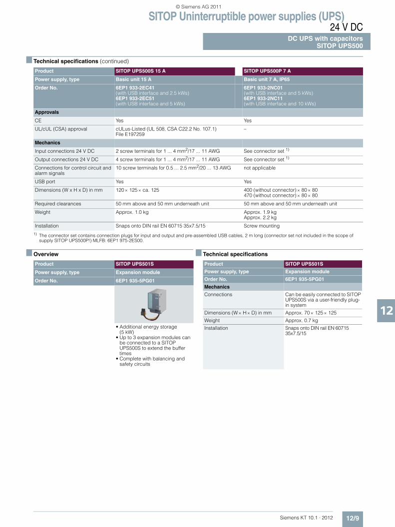
SITOP Uninterruptible power supplies (UPS)24 V DC
DC UPS with capacitorsSITOP UPS500
12/9Siemens KT 10.1 · 2012
12
■ Technical specifications (continued).
1) The connector set contains connection plugs for input and output and pre-assembled USB cables, 2 m long (connector set not included in the scope of supply SITOP UPS500P!) MLFB: 6EP1 975-2ES00.
■ Overview ■ Technical specifications
Product SITOP UPS500S 15 A SITOP UPS500P 7 A
Power supply, type Basic unit 15 A Basic unit 7 A, IP65
Order No. 6EP1 933-2EC41 (with USB interface and 2.5 kWs)6EP1 933-2EC51 (with USB interface and 5 kWs)
6EP1 933-2NC01 (with USB interface and 5 kWs)6EP1 933-2NC11 (with USB interface and 10 kWs)
Approvals
CE Yes Yes
UL/cUL (CSA) approval cULus-Listed (UL 508, CSA C22.2 No. 107.1) File E197259
–
Mechanics
Input connections 24 V DC 2 screw terminals for 1 ... 4 mm2/17 ... 11 AWG See connector set 1)
Output connections 24 V DC 4 screw terminals for 1 ... 4 mm2/17 ... 11 AWG See connector set 1)
Connections for control circuit and alarm signals
10 screw terminals for 0.5 ... 2.5 mm2/20 ... 13 AWG not applicable
USB port Yes Yes
Dimensions (W x H x D) in mm 120 × 125 × ca. 125 400 (without connector) × 80 × 80470 (without connector) × 80 × 80
Required clearances 50 mm above and 50 mm underneath unit 50 mm above and 50 mm underneath unit
Weight Approx. 1.0 kg Approx. 1.9 kgApprox. 2.2 kg
Installation Snaps onto DIN rail EN 60715 35x7.5/15 Screw mounting
Product SITOP UPS501S
Power supply, type Expansion module
Order No. 6EP1 935-5PG01
• Additional energy storage (5 kW)
• Up to 3 expansion modules can be connected to a SITOP UPS500S to extend the buffer times
• Complete with balancing and safety circuits
Product SITOP UPS501S
Power supply, type Expansion module
Order No. 6EP1 935-5PG01
Mechanics
Connections Can be easily connected to SITOP UPS500S via a user-friendly plug-in system
Dimensions (W × H × D) in mm Approx. 70 × 125 × 125
Weight Approx. 0.7 kg
Installation Snaps onto DIN rail EN 60715 35x7.5/15
KT10_EN_gesamt.book Seite 9 Mittwoch, 12. Oktober 2011 11:00 11
© Siemens AG 2011

SITOP Uninterruptible power supplies (UPS)24 V DCDC UPS with battery modulesOverview
12/10 Siemens KT 10.1 · 2012
12
■ Overview
By combining a DC UPS module with at least one 24 V battery module and a SITOP power supply unit, longer power failures can be bridged without any interruption.
The combination is used for example in machine-tool building, in the textile industry, on all types of production lines and filling plants, and in conjunction with 24 V industrial PCs. This prevents the negative effects which often result from power failures.
DC-UPS modules: 6 A, 15 A, 40 A
Battery modules:• 1.2 Ah (contains lead-acid batteries with corrosion-resistant
lead-calcium, high-capacity grid plates and fiberglass mat)• 3.2 Ah (contains lead-acid batteries with corrosion-resistant
lead-calcium, high-capacity grid plates and fiberglass mat)• 7 Ah (contains lead-acid batteries with corrosion-resistant
lead-calcium, high-capacity grid plates and fiberglass mat)• 12 Ah (contains lead-acid batteries with corrosion-resistant
lead-calcium, high-capacity grid plates and fiberglass mat)• 2.5 Ah (contains "high-temperature battery" lead-acid type)
Selection table for battery modules and mains buffering times
Important information for selecting the battery capacity:• The mains buffering times are based on the discharge period
of new or non-aged, fully charged battery modules at a battery temperature of not less than +25 °C down to a battery voltage of 21 V (with voltage drops in the DC UPS, approximately 20.4 V DC still remain for the load).
Battery aging reduces the still available battery capacity up to the end of the service life to typically around 50 % of the original capacity value when new (1.2 Ah or 3.2 Ah or 7 Ah, etc.) and the internal resistance increases. When the message "Battery charge > 85 %" appears, only around 50 % × 85 % = approx. 43 % of the originally available capacity can be assumed at the end of the battery service life.
At battery temperatures below +25 °C, the available capacity drops by another 30 % at + 5 °C battery temperature from ap-prox. 43 % to approx. 70 %. There is then only around 30 % of the original capacity available.
A significantly larger battery capacity must therefore be se-lected when configuring the plant: A drop to approx. 50 % is compensated for by selecting 1 / approx. 0.5 = approx.double the battery capacity (required as per the table for the relevant load current and the relevant buffering time).Available capacity of approx. 43 % is compensated for by selecting 1 / approx. 0.43 = approx. 2.33 times battery capacity. Available capacity of approx. 30 % is compensated for by selecting 1 / approx. 0.3 = approx. 3.33 times battery capacity.
Recommendation:• Instead of installing double the battery capacity to cope with
battery aging, regular battery replacement midway through the expected service life (reduction of capacity to approx. 50 %) can be more advisable for the following reasons: Until the halfway point of the expected battery service life (or slightly beyond), capacity does not drop below 100 %. With regular replacement after halfway through expected service life, only single battery capacity (instead of double capacity) must be installed regarding aging (→ neutral in price with regard to battery module costs but requires only half the space).
• Replacing after half the service life dispenses in particular with the large scatter range of the residual capacity at the end of the service life, which is not accurately defined by battery manufacturers (after the full time, many batteries are above, but many are also below the average of 50 % residual capacity, that is, even if double the capacity is installed, the influence of aging at the end of service life is not reliably compensated for, but only typically) → In the case of replacement after half the expected service life, the configured buffering time is maintained significantly more reliably.
Load current Battery module 1.2 Ah(6EP1935-6MC01)
Battery module 3.2 Ah(6EP1935-6MD11)
Battery module 7 Ah(6EP1935-6ME21)
Battery module 12 Ah (6EP1935-6MF01)
Battery module 2.5 Ah(6EP1935-6MD31)
1 A 30 min 2.5 h 6 h 11 h 2 h
2 A 11 min 45 min 2.5 h 5 h 45 min
3 A 4 min 25 min 1.5 h 3 h 30 min
4 A 2 min 20 min 45 min 2 h 20 min
6 A 1 min 10 min 30 min 1 h 13 min
8 A – 4 min 20 min 40 min 9 min
10 A – 1.5 min 15 min 30 min 7 min
12 A – 1 min 10 min 25 min 5.5 min
14 A – 50 s 8 min 20 min 4.5 min
16 A – 40 s 6 min 15 min 4 min
20 A – – 2 min 11 min –
KT10_EN_gesamt.book Seite 10 Mittwoch, 12. Oktober 2011 11:00 11
© Siemens AG 2011
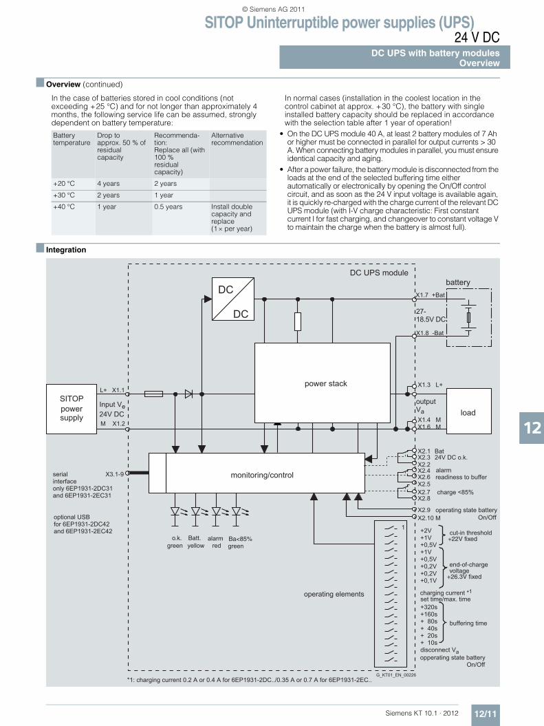
SITOP Uninterruptible power supplies (UPS)24 V DC
DC UPS with battery modulesOverview
12/11Siemens KT 10.1 · 2012
12
■ Overview (continued)
In the case of batteries stored in cool conditions (not exceeding +25 °C) and for not longer than approximately 4 months, the following service life can be assumed, strongly dependent on battery temperature:
In normal cases (installation in the coolest location in the control cabinet at approx. +30 °C), the battery with single installed battery capacity should be replaced in accordance with the selection table after 1 year of operation!
• On the DC UPS module 40 A, at least 2 battery modules of 7 Ah or higher must be connected in parallel for output currents > 30 A. When connecting battery modules in parallel, you must ensure identical capacity and aging.
• After a power failure, the battery module is disconnected from the loads at the end of the selected buffering time either automatically or electronically by opening the On/Off control circuit, and as soon as the 24 V input voltage is available again, it is quickly re-charged with the charge current of the relevant DC UPS module (with I-V charge characteristic: First constant current I for fast charging, and changeover to constant voltage V to maintain the charge when the battery is almost full).
■ Integration
Batterytemperature
Drop toapprox. 50 % of residualcapacity
Recommenda-tion:Replace all (with 100 %residualcapacity)
Alternativerecommendation
+20 °C 4 years 2 years
+30 °C 2 years 1 year
+40 °C 1 year 0.5 years Install double capacity and replace(1 × per year)
1
X3.1-9
L+ X1.1
M X1.2
Input Ve24V DC
DC
DC
X1.7 +Bat
27-18.5V DC
X1.8 -Bat
X1.3 L+
X1.4 M X1.6 M
output Va
X2.1 X2.3 X2.2 X2.4 X2.6 X2.5X2.7 X2.8
X2.9 X2.10 M
+2V+1V+0,5V+1V+0,5V+0,2V +0,2V+0,1V
+320s+160s+ 80s+ 40s+ 20s+ 10s
Bat24V DC o.k.
Batt.o.k. Ba<85%
optional USB for 6EP1931-2DC42 and 6EP1931-2EC42
serialinterfaceonly 6EP1931-2DC31and 6EP1931-2EC31
powersupply
battery
power stack
load
charging current *1set time/max. time
disconnect Va
green yellow greenred
monitoring/control
operating elements
*1: charging current 0.2 A or 0.4 A for 6EP1931-2DC../0.35 A or 0.7 A for 6EP1931-2EC..
readiness to buffer
charge <85%
operating state batteryOn/Off
opperating state battery On/Off
buffering time
cut-in threshold
SITOP
alarm
G_KT01_EN_00226
alarm
end-of-chargevoltage
+22V fixed
+26.3V fixed
DC UPS module
KT10_EN_gesamt.book Seite 11 Mittwoch, 12. Oktober 2011 11:00 11
© Siemens AG 2011

SITOP Uninterruptible power supplies (UPS)24 V DCDC UPS with battery modulesOverview
12/12 Siemens KT 10.1 · 2012
12
■ Function
The following timing diagrams show examples of the characteristic of the input and output voltage at the terminals of the DC UPS module as well as the signal characteristic of the signals (relays) and of the remote signal (port).
"Long" power failure with DC UPS without serial or USB port (Fig. 12/1)
Power restoration only once buffer time tp has expired (t3 follows t4):
Upon failure of the input voltage on the DC UPS module (time t1), the battery "Bat" immediately takes over the DC supply, and the output voltage Vout is then retained absolutely without interruption.
The isolated changeover contact "OK/Bat" switches over to its off position "Bat".
At the same point in time t1, the buffer time tp set on the DIP switches is started automatically.
The fact that the DIP switch is set to "Interruption output Vout" in this example has no effect because the input voltage returns at time t3 only once the set buffer time (time t4) has expired.
"Short" power failure with DC UPS without serial or USB port (Fig. 12/2)
Power restoration before buffer time tp has expired (t3 before t4):
Upon failure of the input voltage on the DC UPS module (time t1), the battery "Bat" immediately takes over the DC supply, and the output voltage Vout is then retained absolutely without interruption.
The isolated changeover contact "OK/Bat" switches over to its off position "Bat".
At the same point in time t1, the buffer time tp set on the DIP switches is started automatically.
With the DIP switch set to "Interruption output Vout", the output voltage Vout is automatically interrupted for 5 s once the set buffer time tp (time t4) has expired.
The battery has already been disconnected because the input voltage has returned at the time t3.
If the DIP switch is not set to "Interruption output Vout", there is no interruption in this example because the input voltage has already returned at time t3 prior to expiry of the set buffer time (time t4).
Figure 12/1 "Long power failure" Figure 12/2 "Short power failure"
DC UPS without serial or USB port (6EP1931-2DC21/-2EC21/-2FC21)
DIP switch settings on device: buffer time tp (from 5 s to 635 s with bottom row nos. 2 to 7) // t = according to setting (with bottom row no. 1 to left) / = with setting for interruption Vout(with bottom row no. 8 to left)
Legend:
Vin
Vout
t1 t4 t3G_KT01_XX_00220
Vin
Vout
t1 t3 t4 t5
Vin: Input voltage at terminals X1.1 – X1.2Vout: Output voltage at terminals X1.3 – X1.4 and X1.5 - X1.6ok: Signal for input voltage Vin OK or above the set battery
connection thresholdBat: Signal for battery operation (batteries connected to output,
batteries supply the load)Remote: Signal for remote timer start with signal level = 0 at pin 7 of
9-pin serial interface (pin 7 is usually the positive power supply for the interface)
t1: Input voltage Vin missing or falls below the set connection threshold
t2: Buffer time set on DIP switches is started by remote timer start (signal level = 0)
t3: Input voltage Vin rises above set connection threshold t4: End of set buffer time (output is switched off and/or battery
is disconnected)t5: Output is connected again 5 s after shutdowntp: Buffer time set on the DIP switches (bottom row nos. 2 to 7)
KT10_EN_gesamt.book Seite 12 Mittwoch, 12. Oktober 2011 11:00 11
© Siemens AG 2011
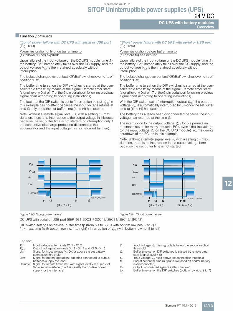
SITOP Uninterruptible power supplies (UPS)24 V DC
DC UPS with battery modulesOverview
12/13Siemens KT 10.1 · 2012
12
■ Function (continued)
"Long" power failure with DC UPS with serial or USB port (Fig. 12/3)
Power restoration only once buffer time tp(t3 follows t4) has expired:
Upon failure of the input voltage on the DC UPS module (time t1), the battery "Bat" immediately takes over the DC supply, and the output voltage Vout is then retained absolutely without interruption.
The isolated changeover contact "OK/Bat" switches over to its off position "Bat".
The buffer time tp set on the DIP switches is started at the user-selectable time t2 by means of the signal "Remote timer start" (signal level = 0 at pin 7 of the 9-pin serial port following previous signal chart according to operating instructions).
The fact that the DIP switch is set to "Interruption output Vout" in this example has no effect because the input voltage returns at time t3 only once the set buffer time (time t4) has expired.
Note: Without a remote signal level = 0 with a setting t = max. duration, there is no interruption to the output voltage in this case because the set buffer time is not started (or interruption only if the exhaustive discharge protection disconnects the accumulator and the input voltage has not returned by then).
"Short" power failure with DC UPS with serial or USB port (Fig. 12/4)
Power restoration before buffer time tp(t3 before t4) has expired:
Upon failure of the input voltage on the DC UPS module (time t1), the battery "Bat" immediately takes over the DC supply, and the output voltage Vout is then retained absolutely without interruption.
The isolated changeover contact "OK/Bat" switches over to its off position "Bat".
The buffer time tp set on the DIP switches is started at the user-selectable time t2 by means of the signal "Remote timer start" (signal level = 0 at pin 7 of the 9-pin serial port following previous signal chart according to operating instructions).
With the DIP switch set to "Interruption output Vout", the output voltage Vout is automatically interrupted for 5 s once the set buffer time tp (time t4) has expired.
The battery has already been disconnected because the input voltage has returned at the time t3.
The interruption to the output voltage Vout for 5 s permits an automatic restart for many industrial PCs, even if the line voltage (or the input voltage Vin on the DC UPS module) returns during shutdown of the PC, as in this example.
Note: Without a remote signal level=0 with a setting t = max. duration, there is no interruption in the output voltage here because the set buffer time is not started.
Figure 12/3 "Long power failure" Figure 12/4 "Short power failure"
DC UPS with serial or USB port (6EP1931-2DC31/-2DC42/-2EC31/-2EC42/-2FC42)
DIP switch settings on device: buffer time tp (from 5 s to 635 s with bottom row nos. 2 to 7) // t = max. time (with bottom row no. 1 to right) / interruption of Vout (with bottom row no. 8 to left)
Legend:
Vin
Vout
t1 t2 t4 t3G_KT01_XX_00222
Vin
Vout
t1 t2 t4 t5t3G_KT01_XX_00223
Vin: Input voltage at terminals X1.1 – X1.2Vout: Output voltage at terminals X1.3 – X1.4 and X1.5 - X1.6ok: Signal for input voltage Vin OK or above the set battery
connection thresholdBat: Signal for battery operation (batteries connected to output,
batteries supply the load)Remote: Signal for remote timer start with signal level = 0 at pin 7 of
9-pin serial interface (pin 7 is usually the positive power supply for the interface)
t1: Input voltage Vin missing or falls below the set connection threshold
t2: Buffer time set on DIP switches is started by remote timer start (signal level = 0)
t3: Input voltage Vin rises above set connection threshold t4: End of set buffer time (output is switched off and/or battery
is disconnected)t5: Output is connected again 5 s after shutdowntp: Buffer time set on the DIP switches (bottom row nos. 2 to 7)
KT10_EN_gesamt.book Seite 13 Mittwoch, 12. Oktober 2011 11:00 11
© Siemens AG 2011

SITOP Uninterruptible power supplies (UPS)24 V DCDC UPS with battery modulesDC UPS modules 6 A, 15 A, 40 A
12/14 Siemens KT 10.1 · 2012
12
■ Overview
■ Technical specifications
1) SIPLUS modules see page 15/4.2) All SITOP 24 V DC power supplies are permissible without restriction.3) In order to implement more than 30 A up to max. 40 A output current for the DC-UPS module 40 A, two 7 Ah or 12 Ah battery modules connected in parallel
are required.
Product DC UPS module DC UPS module DC UPS module
Power supply, type 6 A 15 A 40 A
Order No. 6EP1 931-2DC21 6EP1 931-2DC31(with serial interface)6EP1 931-2DC42(with USB interface)
6EP1 931-2EC21 1) 6EP1 931-2EC31(with serial interface) 6EP1 931-2EC42(with USB interface)
6EP1 931-2FC21 1) 6EP1 931-2FC42(with USB interface)
Product DC UPS module DC UPS module DC UPS module
Power supply, type 6 A 15 A 40 A
Input L+/M in normal operation
Controlled DC voltage Controlled DC voltage Controlled DC voltageRated voltage value Vin rated
2) 24 V DC 24 V DC 24 V DCVoltage range 22 ... 29 V DC 22 ... 29 V DC 22 ... 29 V DC
Connection threshold for battery 22.5 V DC ± 0.1 V (factory setting), adjustable in the range 22 to 25.5 V DC(in 0.5 V increments)
22.5 V DC ± 0.1 V (factory setting), adjustable in the range 22 to 25.5 V DC(in 0.5 V increments)
22.5 V DC ± 0.1 V (factory setting), adjustable in the range 22 to 25.5 V DC(in 0.5 V increments)
Rated current value Iin rated 6 A + approx. 0.6 A with empty battery
15 A +approx. 1 A with empty battery
40 A + approx. 2.6 A with empty battery
Mains buffering
Mains buffering orbuffer time
Dependent on connected battery and load current, see selection table battery module and mains buffering times as well as the relevant important information notes!
On/off control circuit External isolated NO contact required (max. load 15 V DC / max. 10 mA).With an open control circuit, the battery is isolated from output L+, thus canceling mains buffering. If there is no input voltage, a quiescent current of approximately 0.3 mA is drawn from the battery disconnected from the output.
Methods of setting the buffering time
Adjustable using DIP switches to a maximum buffering time up to forced shutdown due to exhaustive discharge protection (at approx. 19 V) or to a time limit of 5 ... 635 s (in 10 s steps)
Interruption Adjustable using DIP switch, either:• Interruption in output voltage despite returning input voltage for min. 5 s following expiry of set buffer time to
support automatic restarting of industrial PCs or• No forced interruption on expiry of the set buffer time
Output L+/M in normal operation
Rated voltage Vout rated 24 V DC (output voltage of SITOP power supply)
24 V DC (output voltage of SITOP power supply)
24 V DC (output voltage of SITOP power supply)
Voltage range Input voltage Vin less approx. 0.5 V DC
Input voltage Vin less approx. 0.5 V DC
Input voltage Vin less approx. 0.5 V DC
Startup delay Approx. 1 s Approx. 1 s Approx. 1 s
Voltage rise Typ. 60 ms Typ. 60 ms Typ. 360 ms
Output current Iout 0 ... 6 A 0 ... 15 A 0 ... 40 A
Dynamic current with overload Electronic current limitation to 1.05 ... 1.4 × Iout rated for approx. 80 ms, then electronic shutdown of the output with automatic restart attempts (approx. 20 s intervals between restart attempts)
Dynamic current with short-circuit Electronic current limitation to1.5 ... 3 × Iout rated for approx.20 ms, then electronic shutdown of the output with automatic restart attempts (approx. 20 s intervals between restart attempts)
Output L+/M with battery operation
Rated voltage Vout rated 24 V DC (from battery module) 24 V DC (from battery module) 24 V DC (from battery module)
Approximate voltage range 27 ... 19 V DC at Iout = 0.05 × C × 1/h or 24 V at Iout = 1 × C × 1/h or 23 V at Iout = 2 × C × 1/h(C = total connected battery capacity in Ah), 19 V switch-off threshold for deep discharge protection
Output current Iout3) 0 ... 6 A (permanently permissible) 0 ... 15 A (permanently
permissible)0 ... 40 A (permanently permissible)
Dynamic current with overload Electronic current limitation to 1.05 ... 1.4 × Iout rated for approx. 80 ms, then latching switch-off ofoutput (restart following return to normal operation)
Dynamic current with short-circuit Electronic current limitation to 1.5 ... 3 × Iout rated for approx. 20 ms, then latching switch-off ofoutput (restart following return to normal operation)
KT10_EN_gesamt.book Seite 14 Mittwoch, 12. Oktober 2011 11:00 11
© Siemens AG 2011

SITOP Uninterruptible power supplies (UPS)24 V DC
DC UPS with battery modulesDC UPS modules 6 A, 15 A, 40 A
12/15Siemens KT 10.1 · 2012
12
■ Technical specifications (continued).
4) Permissible contact rating: 60 V DC/1 A or 30 V AC/1 A.5) "24 V DC OK" means: Voltage of the power supply unit is greater than the battery connection threshold set on the DC UPS module.
Product DC UPS module DC UPS module DC UPS module
Power supply, type 6 A 15 A 40 A
Order No. 6EP1 931-2DC21 6EP1 931-2DC31(with serial interface)6EP1 931-2DC42(with USB interface)
6EP1 931-2EC21 1)
6EP1 931-2EC31(with serial interface) 6EP1 931-2EC42(with USB interface)
6EP1 931-2FC216EP1 931-2FC42(with USB interface)
Output + Bat / – Bat in normal operation
Output +Bat/-Batin normal operation
I-V charging characteristic(first constant current I,then constant voltage V)
I-V charging characteristic(first constant current I,then constant voltage V)
I-V charging characteristic(first constant current I,then constant voltage V)
End-of-charge voltage V 26.6 V DC ± 0.1 V (factory setting for +40 °C battery temperature), adjustable in the range26.3 to 29.3 V (in 0.1 V increments)
26.6 V DC ± 0.1 V (factory setting for +40 °C battery temperature), adjustable in the range26.3 to 29.3 V (in 0.1 V increments)
26.6 V DC ± 0.1 V (factory setting for +40 °C battery temperature), adjustable in the range26.3 to 29.3 V (in 0.1 V increments)
Charging current I Approx. 0.4 A (factory setting), adjustable to 0.2 A or 0.4 A(charging is carried out with closed and open on/off circuit)At a battery voltage of < 6 V (batteries defective), charging is not carried out as a protective measure.
Approx. 0.7 A (factory setting), adjustable to 0.35 A or 0.7 A (charging is carried out with closed and open on/off circuit)At a battery voltage of < 6 V (batteries defective), charging is not carried out as a protective measure.
Approx. 2 A (factory setting), adjustable to 1 A or 2 A(charging is carried out with closed and open on/off circuit)At a battery voltage of < 6 V (batteries defective), charging is not carried out as a protective measure.
Efficiency/heat loss
At Vout rated, Iout rated approx. 95 % / 7 W 96.2 % / 14 W 97.2 % / 28.6 W
With battery operation, approx. 94.5 % / 8 W 96 % / 15 W 96Vin % / 33.6 W
Protection and monitoring
Reverse polarity protection Against polarity reversal on input voltage and batteries
Against polarity reversal on input voltage and batteries
Against polarity reversal on input voltage and batteries
Overload protection In accordance with "dynamic current with overload" in normal operation (automatic restart attempts) or in battery mode (restart following return to normal operation)
Short-circuit protection In accordance with "dynamic current with short-circuit" in normal operation (automatic restart attempts) or in battery mode (restart following return to normal operation). Built-in (not accessible) 16 A fuse (6 A and 15 A on DC UPS module) or 64 A fuse (40 A on DC UPS module).
Exhaustive discharge protection Automatic shutdown when battery voltage falls below approx. 19 V.At a battery voltage of < 6 V (batteries defective), charging is not carried out as a protective measure.
Monitoring "Wire breakage in battery circuit"
Alarm signal if battery circuit not closed or if it opens during operation(cyclic test approximately every 20 s)
Monitoring "Battery replacement required"
Alarm signal flashing at approx. 0.25 Hz repetition frequency(approx. 2 s alarm, approx. 2 s no alarm, approx. 2 s alarm, etc.).Check every 4 hours with6 ohm load for 1 s if no buffer mode or switch-off has taken place within 4 hours.
Alarm signal flashing at approx. 0.25 Hz repetition frequency(approx. 2 s alarm, approx. 2 s no alarm, approx. 2 s alarm, etc.).Check every 4 hours with3 ohm load for 1 s if no buffer mode or switch-off has taken place within 4 hours.
Alarm signal flashing at approx.0.25 Hz repetition frequency(approx. 2 s alarm, approx. 2 sno alarm, approx. 2 s alarm, etc.). Check every 4 hours with 1 ohm load for 1 s if no buffer mode or switch-off has taken place within 4 hours.No monitoring if switch position of compatibility switch is "On"!
Monitoring "Battery charge > 85 %" Indication whether batteries are charged to at least 85 % of residual capacity still available depending on aging
Signaling 4)
Normal operation Green LED (OK) and isolated changeover contact "24 V DC OK / Bat" at setting "24 V DC OK" 5)
Buffer or battery mode (battery supplies load alone or in addition to PS in the case of overload)
Yellow LED (Bat) and isolated changeover contact "24 V DC OK / Bat" at setting "Bat" (= de-energized position)
Alarm (buffer not readyor pre-warning from < 20.4 Vbattery voltage)
Red LED (Alarm) and isolated changeover contact at setting "Alarm" (= de-energized position).Causes of the buffer not being ready during normal operation can include: Off status or open on/off control circuit, battery module not connected, polarity reversal or defective battery (battery voltage< 18.5 V) or wire breakage between battery and UPS module. Scanning and thus updating of the signal every 20 s.Causes of the buffer not being available during buffer operation can include: Accumulator voltage has dropped below 20.4 V DC (= pre-warning before shutdown through exhaustive discharge protection) and shutdown of the accumulator due to overload, short-circuit, exhaustive discharge protection or expired buffer time. The red LED then goes out.
"Battery replacement required" Red LED (alarm) flashing at 0.25 Hz and floating changeover contact (alarm) switching at approx. 0.25 Hz
"Battery charge > 85 %" Second green LED (Bat > 85 %) and floating NO contact closed (de-energized position = open)
KT10_EN_gesamt.book Seite 15 Mittwoch, 12. Oktober 2011 11:00 11
© Siemens AG 2011
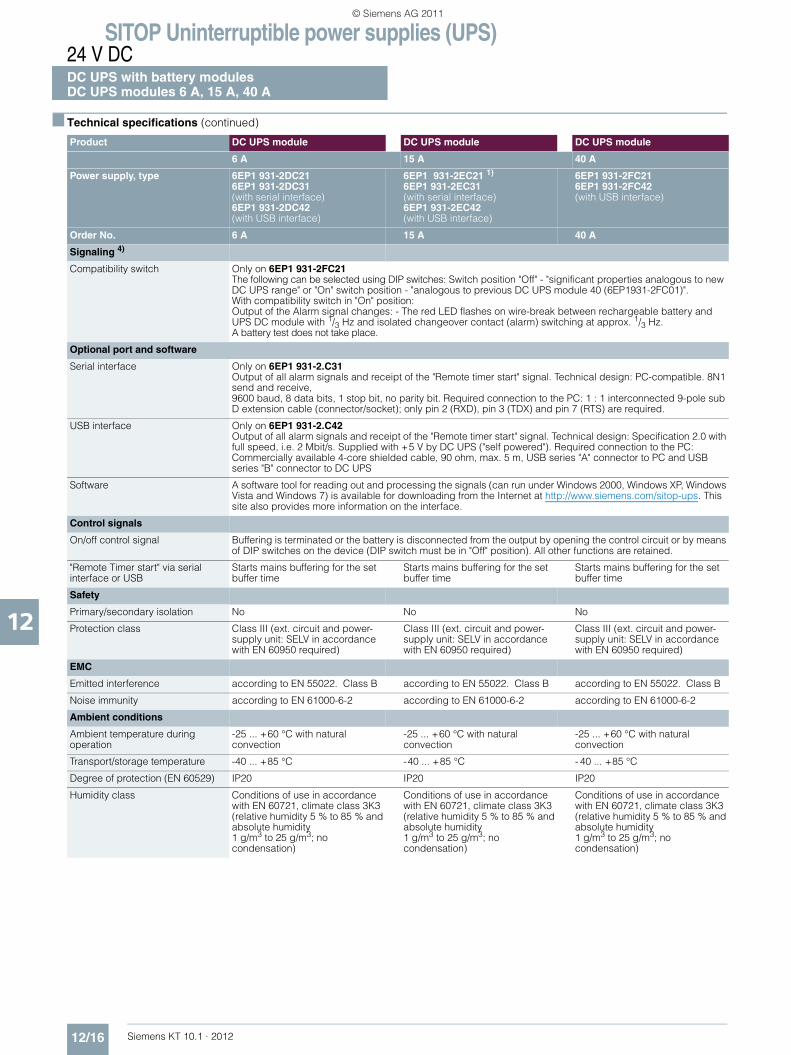
SITOP Uninterruptible power supplies (UPS)24 V DCDC UPS with battery modulesDC UPS modules 6 A, 15 A, 40 A
12/16 Siemens KT 10.1 · 2012
12
■ Technical specifications (continued)
Product DC UPS module DC UPS module DC UPS module
6 A 15 A 40 A
Power supply, type 6EP1 931-2DC21 6EP1 931-2DC31(with serial interface)6EP1 931-2DC42(with USB interface)
6EP1 931-2EC21 1) 6EP1 931-2EC31(with serial interface) 6EP1 931-2EC42(with USB interface)
6EP1 931-2FC216EP1 931-2FC42(with USB interface)
Order No. 6 A 15 A 40 A
Signaling 4)
Compatibility switch Only on 6EP1 931-2FC21The following can be selected using DIP switches: Switch position "Off" - "significant properties analogous to new DC UPS range" or "On" switch position - "analogous to previous DC UPS module 40 (6EP1931-2FC01)".With compatibility switch in "On" position:Output of the Alarm signal changes: - The red LED flashes on wire-break between rechargeable battery and UPS DC module with 1/3 Hz and isolated changeover contact (alarm) switching at approx. 1/3 Hz. A battery test does not take place.
Optional port and software
Serial interface Only on 6EP1 931-2.C31Output of all alarm signals and receipt of the "Remote timer start" signal. Technical design: PC-compatible. 8N1 send and receive, 9600 baud, 8 data bits, 1 stop bit, no parity bit. Required connection to the PC: 1 : 1 interconnected 9-pole sub D extension cable (connector/socket); only pin 2 (RXD), pin 3 (TDX) and pin 7 (RTS) are required.
USB interface Only on 6EP1 931-2.C42Output of all alarm signals and receipt of the "Remote timer start" signal. Technical design: Specification 2.0 with full speed, i.e. 2 Mbit/s. Supplied with +5 V by DC UPS ("self powered"). Required connection to the PC: Commercially available 4-core shielded cable, 90 ohm, max. 5 m, USB series "A" connector to PC and USB series "B" connector to DC UPS
Software A software tool for reading out and processing the signals (can run under Windows 2000, Windows XP, Windows Vista and Windows 7) is available for downloading from the Internet at http://www.siemens.com/sitop-ups. This site also provides more information on the interface.
Control signals
On/off control signal Buffering is terminated or the battery is disconnected from the output by opening the control circuit or by means of DIP switches on the device (DIP switch must be in "Off" position). All other functions are retained.
"Remote Timer start" via serial interface or USB
Starts mains buffering for the set buffer time
Starts mains buffering for the set buffer time
Starts mains buffering for the set buffer time
Safety
Primary/secondary isolation No No No
Protection class Class III (ext. circuit and power-supply unit: SELV in accordance with EN 60950 required)
Class III (ext. circuit and power-supply unit: SELV in accordance with EN 60950 required)
Class III (ext. circuit and power-supply unit: SELV in accordance with EN 60950 required)
EMC
Emitted interference according to EN 55022. Class B according to EN 55022. Class B according to EN 55022. Class B
Noise immunity according to EN 61000-6-2 according to EN 61000-6-2 according to EN 61000-6-2
Ambient conditions
Ambient temperature during operation
-25 ... +60 °C with natural convection
-25 ... +60 °C with natural convection
-25 ... +60 °C with natural convection
Transport/storage temperature -40 ... +85 °C -40 ... +85 °C - 40 ... +85 °C
Degree of protection (EN 60529) IP20 IP20 IP20
Humidity class Conditions of use in accordance with EN 60721, climate class 3K3(relative humidity 5 % to 85 % and absolute humidity1 g/m3 to 25 g/m3; nocondensation)
Conditions of use in accordance with EN 60721, climate class 3K3(relative humidity 5 % to 85 % and absolute humidity1 g/m3 to 25 g/m3; nocondensation)
Conditions of use in accordance with EN 60721, climate class 3K3(relative humidity 5 % to 85 % and absolute humidity1 g/m3 to 25 g/m3; nocondensation)
KT10_EN_gesamt.book Seite 16 Mittwoch, 12. Oktober 2011 11:00 11
© Siemens AG 2011

SITOP Uninterruptible power supplies (UPS)24 V DC
DC UPS with battery modulesDC UPS modules 6 A, 15 A, 40 A
12/17Siemens KT 10.1 · 2012
12
■ Technical specifications (continued)
Product DC UPS module DC UPS module DC UPS module
6 A 15 A 40 A
Power supply, type 6EP1 931-2DC21 6EP1 931-2DC31(with serial interface)6EP1 931-2DC42(with USB interface)
6EP1 931-2EC21 1)) 6EP1 931-2EC31(with serial interface) 6EP1 931-2EC42(with USB interface)
6EP1 931-2FC216EP1 931-2FC42(with USB interface)
Order No. 6 A 15 A 40 A
Approvals
CE mark Yes Yes Yes
UL/cUL (CSA) approval cULus-Listed (UL 508, CSA C22.2 No.107.1), File E197259
cULus-Listed (UL 508, CSA C22.2 No. 107.1), File E197259
cULus-Listed (UL 508, CSA C22.2 No. 107.1), File E197259
Mechanics
Input connections 24 V DC 2 screw terminalsfor 1 ... 4 mm2/17 ... 11 AWG
2 screw terminalsfor 1 ... 4 mm2/17 ... 11 AWG
2 screw terminals for0.33 ... 10 mm2/22 ... 7 AWG
Output connections 24 V DC 4 screw terminals for1 ... 4 mm2/17 ... 11 AWG
4 screw terminals for1 ... 4 mm2/17 ... 11 AWG
4 screw terminals for0.33 ... 10 mm2/22 ... 7 AWG
Connections for rechargeable battery 24 V DC
2 screw terminalsfor 1 ... 4 mm2/17 ... 11 AWG
2 screw terminalsfor 1 ... 4 mm2/17 ... 11 AWG
2 screw terminals for0.33 ... 10 mm2/22 ... 7 AWG
Connections for control circuit and alarm signals
10 screw terminals for0.5 ... 2.5 mm2/20 ... 13 AWG
10 screw terminals for0.5 ... 2.5 mm2/20 ... 13 AWG
10 screw terminals for0.5 ... 2.5 mm2/20 ... 13 AWG
Dimensions (W × H × D) in mm 50 × 125 × approx. 125 50 × 125 × approx. 125 102 × 125 × 125
Weight, approx. 0.4 kg (with serial or USB interface: 0.45 kg)
0.4 kg (with serial or USB interface: 0.45 kg)
1.1 kg (with serial or USB interface: 1.1 kg)
Installation Snaps onto DIN rail EN 60715 35x7.5/15
Snaps onto DIN rail EN 60715 35x7.5/15
Snaps onto DIN rail EN 60715 35x7.5/15
KT10_EN_gesamt.book Seite 17 Mittwoch, 12. Oktober 2011 11:00 11
© Siemens AG 2011
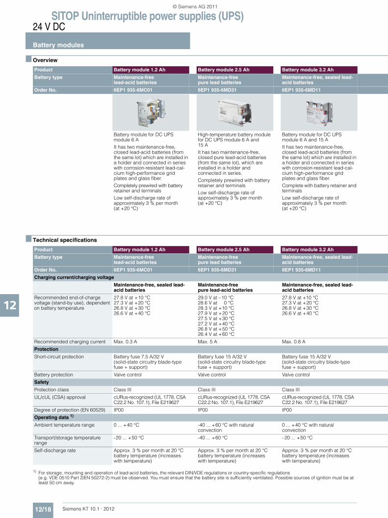
SITOP Uninterruptible power supplies (UPS)24 V DC
Battery modules
12/18 Siemens KT 10.1 · 2012
12
■ Overview
■ Technical specifications
1) For storage, mounting and operation of lead-acid batteries, the relevant DIN/VDE regulations or country-specific regulations (e.g. VDE 0510 Part 2/EN 50272-2) must be observed. You must ensure that the battery site is sufficiently ventilated. Possible sources of ignition must be at least 50 cm away.
Product Battery module 1.2 Ah Battery module 2.5 Ah Battery module 3.2 Ah
Battery type Maintenance-free lead-acid batteries
Maintenance-free pure lead batteries
Maintenance-free, sealed lead-acid batteries
Order No. 6EP1 935-6MC01 6EP1 935-6MD31 6EP1 935-6MD11
Battery module for DC UPS module 6 AIt has two maintenance-free, closed lead-acid batteries (from the same lot) which are installed in a holder and connected in series with corrosion-resistant lead-cal-cium high-performance grid plates and glass fiber.Completely prewired with battery retainer and terminalsLow self-discharge rate of approximately 3 % per month (at +20 °C)
High-temperature battery module for DC UPS module 6 A and15 AIt has two maintenance-free, closed pure lead-acid batteries (from the same lot), which are installed in a holder and connected in series. Completely prewired with battery retainer and terminalsLow self-discharge rate of approximately 3 % per month (at +20 °C)
Battery module for DC UPS module 6 A and 15 AIt has two maintenance-free, closed lead-acid batteries (from the same lot) which are installed in a holder and connected in series with corrosion-resistant lead-cal-cium high-performance grid plates and glass fiber.Complete with battery retainer and terminalsLow self-discharge rate of approximately 3 % per month (at +20 °C)
Product Battery module 1.2 Ah Battery module 2.5 Ah Battery module 3.2 Ah
Battery type Maintenance-free lead-acid batteries
Maintenance-free pure lead batteries
Maintenance-free, sealed lead-acid batteries
Order No. 6EP1 935-6MC01 6EP1 935-6MD31 6EP1 935-6MD11
Charging current/charging voltage
Maintenance-free, sealed lead-acid batteries
Maintenance-free pure lead-acid batteries
Maintenance-free, sealed lead-acid batteries
Recommended end-of-charge voltage (stand-by use), dependent on battery temperature
27.8 V at +10 °C27.3 V at +20 °C26.8 V at +30 °C 26.6 V at +40 °C
29.0 V at –10 °C28.6 V at 0 °C28.3 V at +10 °C27.9 V at +20 °C27.5 V at +30 °C27.2 V at +40 °C26.8 V at +50 °C26.4 V at +60 °C
27.8 V at +10 °C27.3 V at +20 °C26.8 V at +30 °C26.6 V at +40 °C
Recommended charging current Max. 0.3 A Max. 5 A Max. 0.8 A
Protection
Short-circuit protection Battery fuse 7.5 A/32 V (solid-state circuitry blade-type fuse + support)
Battery fuse 15 A/32 V (solid-state circuitry blade-type fuse + support)
Battery fuse 15 A/32 V (solid-state circuitry blade-type fuse + support)
Battery protection Valve control Valve control Valve control
Safety
Protection class Class III Class III Class III
UL/cUL (CSA) approval cURus-recognized (UL 1778, CSA C22.2 No. 107.1), File E219627
cURus-recognized (UL 1778, CSA C22.2 No. 107.1), File E219627
cURus-recognized (UL 1778, CSA C22.2 No. 107.1), File E219627
Degree of protection (EN 60529) IP00 IP00 IP00
Operating data 1)
Ambient temperature range 0 ... +40 °C -40 ... +60 °C with natural convection
0 ... +40 °C with natural convection
Transport/storage temperature range
-20 ... +50 °C -40 ... +60 °C - 20 ... +50 °C
Self-discharge rate Approx. 3 % per month at 20 °Cbattery temperature (increases with temperature)
Approx. 3 % per month at 20 °Cbattery temperature (increases with temperature)
Approx. 3 % per month at 20 °Cbattery temperature (increases with temperature)
KT10_EN_gesamt.book Seite 18 Mittwoch, 12. Oktober 2011 11:00 11
© Siemens AG 2011
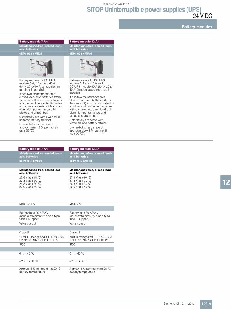
SITOP Uninterruptible power supplies (UPS)24 V DC
Battery modules
12/19Siemens KT 10.1 · 2012
12
Battery module 7 Ah Battery module 12 Ah
Maintenance-free, sealed lead-acid batteries
Maintenance-free, sealed lead-acid batteries
6EP1 935-6ME21 6EP1 935-6MF01
Battery module for DC UPS module 6 A, 15 A, and 40 A (for > 20 to 40 A, 2 modules are required in parallel).It has two maintenance-free, closed lead-acid batteries (from the same lot) which are installed in a holder and connected in series with corrosion-resistant lead-cal-cium high-performance grid plates and glass fiber.Completely pre-wired with termi-nals and battery retainerLow self-discharge rate of approximately 3 % per month (at +20 °C)
Battery module for DC UPS module 6 A and 15 A and DC UPS module 40 A (for > 20 to 40 A, 2 modules are required in parallel)It has two maintenance-free, closed lead-acid batteries (from the same lot) which are installed in a holder and connected in series with corrosion-resistant lead-cal-cium high-performance grid plates and glass fiber.Completely pre-wired with terminals and battery retainerLow self-discharge rate of approximately 3 % per month (at +20 °C).
Battery module 7 Ah Battery module 12 Ah
Maintenance-free, sealed lead-acid batteries
Maintenance-free, sealed lead-acid batteries
6EP1 935-6ME21 6EP1 935-6MF01
Maintenance-free, sealed lead-acid batteries
Maintenance-free, closed lead-acid batteries
27.8 V at +10 °C27.3 V at +20 °C26.8 V at +30 °C26.6 V at +40 °C
27.8 V at +10 °C27.3 V at +20 °C26.8 V at +30 °C26.6 V at +40 °C
Max. 1.75 A Max. 3 A
Battery fuse 30 A/32 V (solid-state circuitry blade-type fuse + support)
Battery fuse 30 A/32 V (solid-state circuitry blade-type fuse + support)
Valve control Valve control
Class III Class III
UL/cUL-Recognized (UL 1778, CSA C22.2 No. 107.1), File E219627
cURus-recognized (UL 1778, CSA C22.2 No. 107.1), File E219627
IP00 IP00
0 ... +40 °C 0 ... +40 °C
– 20 ... +50 °C – 20 ... +50 °C
Approx. 3 % per month at 20 °C battery temperature
Approx. 3 % per month at 20 °C battery temperature
KT10_EN_gesamt.book Seite 19 Mittwoch, 12. Oktober 2011 11:00 11
© Siemens AG 2011
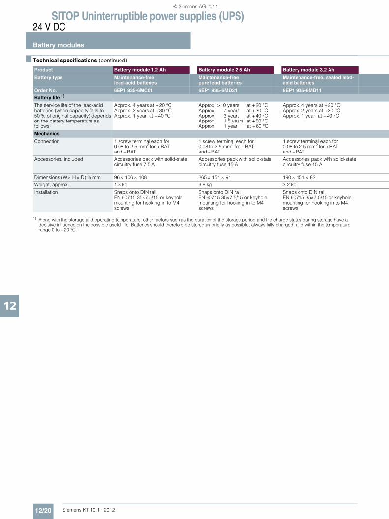
SITOP Uninterruptible power supplies (UPS)24 V DC
Battery modules
12/20 Siemens KT 10.1 · 2012
12
■ Technical specifications (continued).
1) Along with the storage and operating temperature, other factors such as the duration of the storage period and the charge status during storage have a decisive influence on the possible useful life. Batteries should therefore be stored as briefly as possible, always fully charged, and within the temperature range 0 to +20 °C.
Product Battery module 1.2 Ah Battery module 2.5 Ah Battery module 3.2 Ah
Battery type Maintenance-free lead-acid batteries
Maintenance-free pure lead batteries
Maintenance-free, sealed lead-acid batteries
Order No. 6EP1 935-6MC01 6EP1 935-6MD31 6EP1 935-6MD11
Battery life 1)
The service life of the lead-acid batteries (when capacity falls to 50 % of original capacity) depends on the battery temperature as follows:
Approx. 4 years at +20 °CApprox. 2 years at +30 °CApprox. 1 year at +40 °C
Approx. >10 years at +20 °CApprox. 7 years at +30 °CApprox. 3 years at +40 °CApprox. 1.5 years at +50 °CApprox. 1 year at +60 °C
Approx. 4 years at +20 °CApprox. 2 years at +30 °CApprox. 1 year at +40 °C
Mechanics
Connection 1 screw terminal each for0.08 to 2.5 mm2 for +BATand – BAT
1 screw terminal each for0.08 to 2.5 mm2 for +BATand – BAT
1 screw terminal each for0.08 to 2.5 mm2 for +BATand – BAT
Accessories, included Accessories pack with solid-state circuitry fuse 7.5 A
Accessories pack with solid-state circuitry fuse 15 A
Accessories pack with solid-state circuitry fuse 15 A
Dimensions (W × H × D) in mm 96 × 106 × 108 265 × 151 × 91 190 × 151 × 82
Weight, approx. 1.8 kg 3.8 kg 3.2 kg
Installation Snaps onto DIN railEN 60715 35×7.5/15 or keyhole mounting for hooking in to M4 screws
Snaps onto DIN railEN 60715 35×7.5/15 or keyhole mounting for hooking in to M4 screws
Snaps onto DIN railEN 60715 35×7.5/15 or keyhole mounting for hooking in to M4 screws
KT10_EN_gesamt.book Seite 20 Mittwoch, 12. Oktober 2011 11:00 11
© Siemens AG 2011
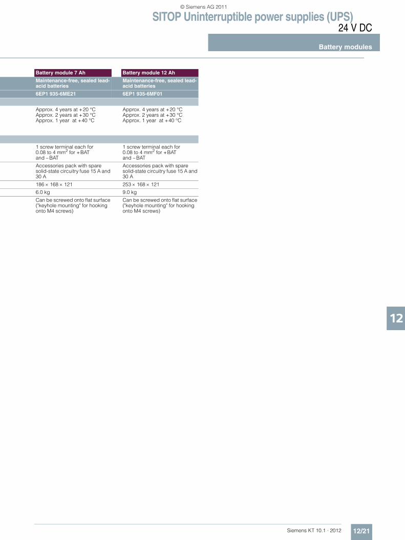
SITOP Uninterruptible power supplies (UPS)24 V DC
Battery modules
12/21Siemens KT 10.1 · 2012
12
Battery module 7 Ah Battery module 12 Ah
Maintenance-free, sealed lead-acid batteries
Maintenance-free, sealed lead-acid batteries
6EP1 935-6ME21 6EP1 935-6MF01
Approx. 4 years at +20 °CApprox. 2 years at +30 °CApprox. 1 year at +40 °C
Approx. 4 years at +20 °CApprox. 2 years at +30 °CApprox. 1 year at +40 °C
1 screw terminal each for0.08 to 4 mm2 for +BAT and – BAT
1 screw terminal each for0.08 to 4 mm2 for +BAT and – BAT
Accessories pack with spare solid-state circuitry fuse 15 A and 30 A
Accessories pack with spare solid-state circuitry fuse 15 A and 30 A
186 × 168 × 121 253 × 168 × 121
6.0 kg 9.0 kg
Can be screwed onto flat surface ("keyhole mounting" for hooking onto M4 screws)
Can be screwed onto flat surface ("keyhole mounting" for hooking onto M4 screws)
KT10_EN_gesamt.book Seite 21 Mittwoch, 12. Oktober 2011 11:00 11
© Siemens AG 2011
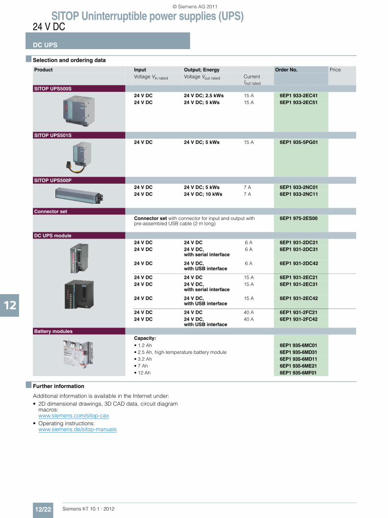
SITOP Uninterruptible power supplies (UPS)24 V DC
DC UPS
12/22 Siemens KT 10.1 · 2012
12
■ Selection and ordering data
■ Further information
Additional information is available in the Internet under:• 2D dimensional drawings, 3D CAD data, circuit diagram
macros: www.siemens.com/sitop-cax
• Operating instructions:www.siemens.de/sitop-manuals
Product Input Output; Energy Order No. PriceVoltage Vin rated Voltage Vout rated Current
Iout ratedSITOP UPS500S
24 V DC 24 V DC; 2.5 kWs 15 A 6EP1 933-2EC41 24 V DC 24 V DC; 5 kWs 15 A 6EP1 933-2EC51
SITOP UPS501S24 V DC 24 V DC; 5 kWs 15 A 6EP1 935-5PG01
SITOP UPS500P24 V DC 24 V DC; 5 kWs 7 A 6EP1 933-2NC01 24 V DC 24 V DC; 10 kWs 7 A 6EP1 933-2NC11
Connector set Connector set with connector for input and output with pre-assembled USB cable (2 m long)
6EP1 975-2ES00
DC UPS module 24 V DC 24 V DC 6 A 6EP1 931-2DC21 24 V DC 24 V DC,
with serial interface 6 A 6EP1 931-2DC31
24 V DC 24 V DC,with USB interface
6 A 6EP1 931-2DC42
24 V DC 24 V DC 15 A 6EP1 931-2EC2124 V DC 24 V DC,
with serial interface15 A 6EP1 931-2EC31
24 V DC 24 V DC,with USB interface
15 A 6EP1 931-2EC42
24 V DC 24 V DC 40 A 6EP1 931-2FC2124 V DC 24 V DC,
with USB interface40 A 6EP1 931-2FC42
Battery modules Capacity:• 1.2 Ah 6EP1 935-6MC01 • 2.5 Ah, high-temperature battery module 6EP1 935-6MD31• 3.2 Ah 6EP1 935-6MD11• 7 Ah 6EP1 935-6ME21• 12 Ah 6EP1 935-6MF01
KT10_EN_gesamt.book Seite 22 Mittwoch, 12. Oktober 2011 11:00 11
© Siemens AG 2011

Siemens KT 10.1 · 2012
1313/2 Output voltage 3-52 V
SITOP flexi
13/4 Output voltage 5 V13/4 LOGO!Power 5 V/3 A13/4 LOGO!Power 5 V/6.3 A
13/6 Output voltage 12 V13/6 LOGO!Power 12 V/1.9 A13/6 SITOP PSU100C 12 V/2 A13/6 SITOP DC/12 V DC/2.5 A13/7 PSU100D 12 V/3 A13/7 LOGO!Power 12 V/4.5 A13/7 SITOP PSU100C 12 V/6.5 A13/10 PSU100D 12 V/8.3 A13/10 SITOP PSU300B 12 V/20 A
13/12 Output voltage 15 V13/12 LOGO!Power 15 V/1.9 A13/12 LOGO!Power 15 V/4 A13/12 SITOP dual 2 x 15 V/3.5 A
13/14 Output voltage 48 V13/14 SITOP PSU300M 48 V/10 A13/14 SITOP modular 48 V/20 A
13/16 Ordering data and additional information
SITOP Alternative voltages
Export regulations AL and ECCNsee page 17/9
KT10_EN_gesamt.book Seite 1 Mittwoch, 12. Oktober 2011 11:00 11
© Siemens AG 2011

SITOPAlternative voltages
Output voltages 3 - 52 V
13/2 Siemens KT 10.1 · 2012
13
■ Overview
■ Technical specifications
Product Special designSITOP flexi
Power supply, type 3-52 V/2-10 A
Order No. 6EP1 353-2BA00
The power supply with flexible output voltage from 3 to 52 V; suitable for all application areas requiring a special voltage other than 24 V.
Product Special designSITOP flexi
Input
1-phase ACRated voltage value Vin rated 120/230 V AC
Set via wire jumperVoltage range 85 ... 132 V/170 ... 264 V
Overvoltage resistance 2.3 × Vin rated.1.3 ms Mains buffering at Iout rated > 10 ms at Vin = 93/187 V
(Pa = 120 W) Rated line frequency value; range 50/60 Hz, 47 ... 63 Hz
Rated current Iin rated 2.2/0.9 ASwitch-on current limit (+25 °C) < 32 AI2t < 0.8 A2s
Built-in incoming fuse T 3.15 A/250 V (not accessible)Recommended miniature circuit breaker (IEC 898) in the mains power input
From 6 A, characteristic C
Output
Controlled, isolated DC voltageRated voltage Vout rated 3-52 V DC
Total tolerance ±1 %• Static line compensation Approx. 0.1 %• Static load compensation Approx. 0.2 %
Sense line connection Yes, maximum voltage control 0.5 V per line
Residual ripple < 50 mVpp (typ. 20 mVpp)Spikes (bandwidth: 20 MHz) < 100 mVpp (typ. 80 mVpp)
Adjustment range 3 ... 52 V, via potentiometer or analog control voltage signal 0 ... 2.5 VStatus display Green LED for 24 V OKSignaling Power good via relay contact, current monitor signal 0 ... 2.5 VOn/off behavior No overshoot of Vout
(soft start)
Startup delay /voltage rise
< 3 s/typ. 80 ms
Rated current value Iout rated 2 to 10 A (max. 120 W)
Current range • Up to +60 °C 0 ... 10 A (max. 120 W) • Derating –
Dynamic overcurrent on • Power-up on short-circuit Constant current 2 ... 10 A• Short circuit during operation Constant current 2 ... 10 A
Parallel switching for enhanced performance
Yes, 2 units
KT10_EN_gesamt.book Seite 2 Mittwoch, 12. Oktober 2011 11:00 11
© Siemens AG 2011
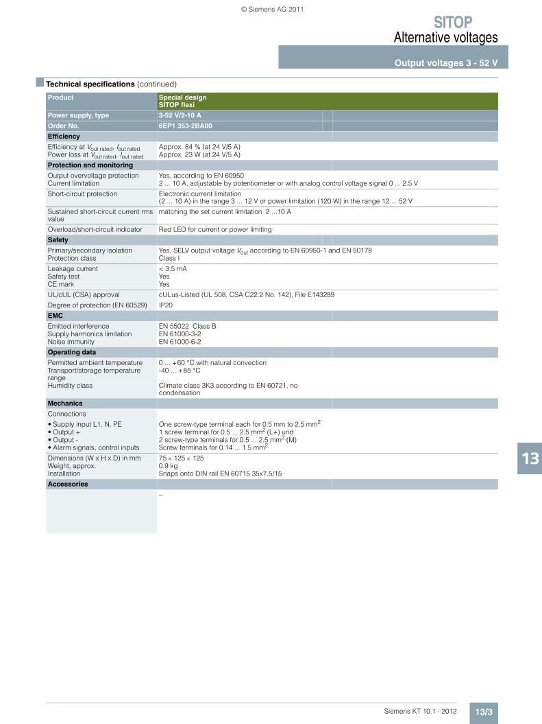
SITOPAlternative voltages
Output voltages 3 - 52 V
13/3Siemens KT 10.1 · 2012
13
■ Technical specifications (continued)
Product Special designSITOP flexi
Power supply, type 3-52 V/2-10 A
Order No. 6EP1 353-2BA00
Efficiency
Efficiency at Vout rated, Iout rated Approx. 84 % (at 24 V/5 A)Power loss at Vout rated, Iout rated Approx. 23 W (at 24 V/5 A)
Protection and monitoring
Output overvoltage protection Yes, according to EN 60950Current limitation 2 ... 10 A, adjustable by potentiometer or with analog control voltage signal 0 ... 2.5 V
Short-circuit protection Electronic current limitation (2 ... 10 A) in the range 3 ... 12 V or power limitation (120 W) in the range 12 ... 52 V
Sustained short-circuit current rms value
matching the set current limitation 2 ...10 A
Overload/short-circuit indicator Red LED for current or power limiting
Safety
Primary/secondary isolation Yes, SELV output voltage Vout according to EN 60950-1 and EN 50178Protection class Class I
Leakage current < 3.5 mASafety test YesCE mark Yes
UL/cUL (CSA) approval cULus-Listed (UL 508, CSA C22.2 No. 142), File E143289
Degree of protection (EN 60529) IP20
EMC
Emitted interference EN 55022 Class BSupply harmonics limitation EN 61000-3-2Noise immunity EN 61000-6-2
Operating data
Permitted ambient temperature 0 ... +60 °C with natural convectionTransport/storage temperature range
-40 ... +85 °C
Humidity class Climate class 3K3 according to EN 60721, no condensation
Mechanics
Connections
• Supply input L1, N, PE One screw-type terminal each for 0.5 mm to 2.5 mm2
• Output + 1 screw terminal for 0.5 ... 2.5 mm2 (L+) und• Output - 2 screw-type terminals for 0.5 ... 2.5 mm2 (M)• Alarm signals, control inputs Screw terminals for 0.14 ... 1.5 mm2
Dimensions (W x H x D) in mm 75 × 125 × 125Weight, approx. 0.9 kgInstallation Snaps onto DIN rail EN 60715 35x7.5/15
Accessories
–
KT10_EN_gesamt.book Seite 3 Mittwoch, 12. Oktober 2011 11:00 11
© Siemens AG 2011
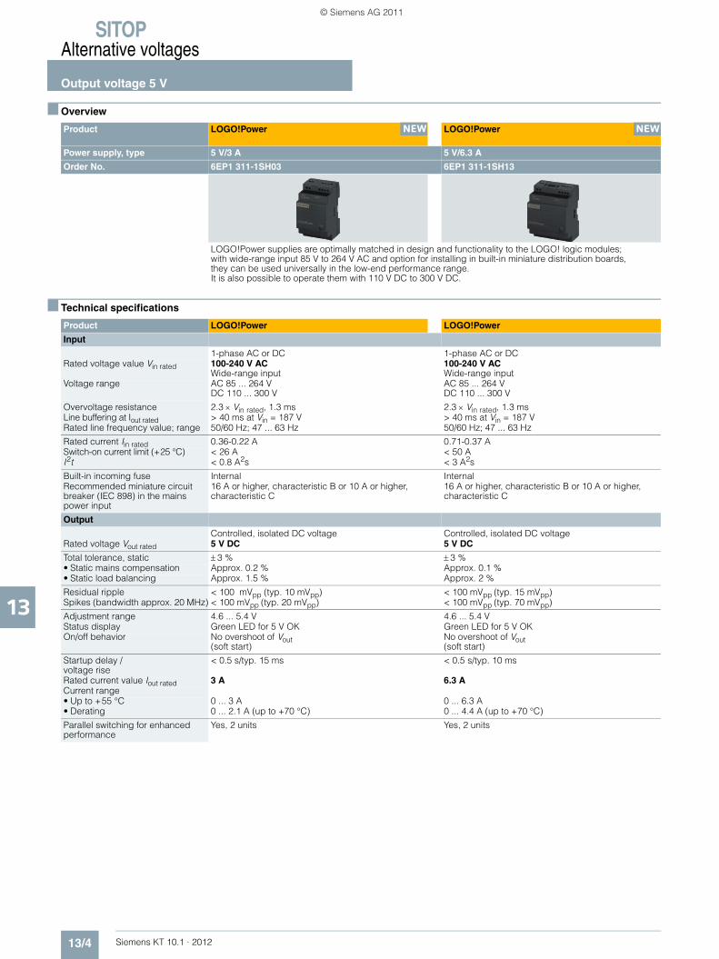
SITOPAlternative voltages
Output voltage 5 V
13/4 Siemens KT 10.1 · 2012
13
■ Overview
■ Technical specifications
Product LOGO!Power LOGO!Power
Power supply, type 5 V/3 A 5 V/6.3 A
Order No. 6EP1 311-1SH03 6EP1 311-1SH13
LOGO!Power supplies are optimally matched in design and functionality to the LOGO! logic modules; with wide-range input 85 V to 264 V AC and option for installing in built-in miniature distribution boards, they can be used universally in the low-end performance range. It is also possible to operate them with 110 V DC to 300 V DC.
Product LOGO!Power LOGO!Power
Input
1-phase AC or DC 1-phase AC or DCRated voltage value Vin rated 100-240 V AC
Wide-range input100-240 V AC Wide-range input
Voltage range AC 85 ... 264 VDC 110 ... 300 V
AC 85 ... 264 VDC 110 ... 300 V
Overvoltage resistance 2.3 × Vin rated, 1.3 ms 2.3 × Vin rated, 1.3 msLine buffering at Iout rated > 40 ms at Vin = 187 V > 40 ms at Vin = 187 VRated line frequency value; range 50/60 Hz; 47 ... 63 Hz 50/60 Hz; 47 ... 63 Hz
Rated current Iin rated 0.36-0.22 A 0.71-0.37 ASwitch-on current limit (+25 °C) < 26 A < 50 AI2t < 0.8 A2s < 3 A2s
Built-in incoming fuse Internal InternalRecommended miniature circuit breaker (IEC 898) in the mains power input
16 A or higher, characteristic B or 10 A or higher, characteristic C
16 A or higher, characteristic B or 10 A or higher, characteristic C
Output
Controlled, isolated DC voltage Controlled, isolated DC voltageRated voltage Vout rated 5 V DC 5 V DC
Total tolerance, static ± 3 % ± 3 %• Static mains compensation Approx. 0.2 % Approx. 0.1 %• Static load balancing Approx. 1.5 % Approx. 2 %
Residual ripple < 100 mVpp (typ. 10 mVpp) < 100 mVpp (typ. 15 mVpp)Spikes (bandwidth approx. 20 MHz) < 100 mVpp (typ. 20 mVpp) < 100 mVpp (typ. 70 mVpp)
Adjustment range 4.6 ... 5.4 V 4.6 ... 5.4 VStatus display Green LED for 5 V OK Green LED for 5 V OKOn/off behavior No overshoot of Vout
(soft start)No overshoot of Vout (soft start)
Startup delay /voltage rise
< 0.5 s/typ. 15 ms < 0.5 s/typ. 10 ms
Rated current value Iout rated 3 A 6.3 ACurrent range • Up to +55 °C 0 ... 3 A 0 ... 6.3 A• Derating 0 ... 2.1 A (up to +70 °C) 0 ... 4.4 A (up to +70 °C)
Parallel switching for enhanced performance
Yes, 2 units Yes, 2 units
NEW NEW
KT10_EN_gesamt.book Seite 4 Mittwoch, 12. Oktober 2011 11:00 11
© Siemens AG 2011

SITOPAlternative voltages
Output voltage 5 V
13/5Siemens KT 10.1 · 2012
13
■ Technical specifications (continued)
Product LOGO!Power LOGO!Power
Power supply, type 5 V/3 A 5 V/6.3 A
Order No. 6EP1 311-1SH03 6EP1 311-1SH13
Efficiency
Efficiency at Vout rated, Iout rated Approx. 77 % Approx. 83 %Power loss at Vout rated, Iout rated Approx. 4 W Approx. 6 W
Closed-loop control
Dyn. mains compensation (Vin rated ± 15 %)
<0.2 % Vout <0.2 % Vout
Dynamic load smoothing (Iout: 10/90/10 %)
Typ. ± 3 % Vout Typ. ± 3 % Vout
Load-step settling time • 10 at 90 % Typ. 2 ms Typ. 2 ms• 90 at 10 % Typ. 2 ms Typ. 2 ms
Protection and monitoring
Current limitation Typically 3.8 A Typically 8.2 AShort-circuit protection Constant current characteristic Constant current characteristicSustained short-circuit current rms value
< 5 A < 10 A
Overload/short-circuit indicator – –
Safety
Primary/secondary isolation Yes, SELV output voltage Vout according to EN 60950-1 and EN 50178
Yes, SELV output voltage Vout according to EN 60950-1 and EN 50178
Protection class Class II (without protective conductor)) Class II (without protective conductor))
Safety test Yes; CB Scheme Yes; CB SchemeCE mark Yes Yes
UL/cUL (CSA) approval cULus-Listed (UL 508, CSA C22.2 No. 107.1), File E197259; cURus-Recognized (UL 60950, CSA C22.2 No. 60950), File E197259
cULus-Listed (UL 508, CSA C22.2 No. 107.1), File E197259; cURus-Recognized (UL 60950, CSA C22.2 No. 60950), File 197259
Explosion protection ATEX (EX) II 3G Ex nA IIC T3; cCSAus (CSA E60079, UL 60079), Class I, Div. 2. Group ABCD, T4
ATEX (EX) II 3G Ex nA IIC T3; cCSAus (CSA E60079, UL 60079), Class I, Div. 2. Group ABCD, T4
FM approval Class I, Div. 2. Group ABCD, T4 Class I, Div. 2. Group ABCD, T4Marine approval GL GLDegree of protection (EN 60529) IP20 IP20
EMC
Emitted interference EN 55022 Class B EN 55022 Class BSupply harmonics limitation Not applicable Not applicableNoise immunity EN 61000-6-2 EN 61000-6-2
Operating data
Permitted ambient temperature - 20 ... +70 °C with natural convection -20 ... +70 °C with natural convection Transport/storage temperature range
- 40 ... +85 °C -40 ... +85 °C
Humidity class Climate class 3K3 according to EN 60721, no condensation
Climate class 3K3 according to EN 60721, no condensation
Mechanics
Supply-input connections L1, N One screw-type terminal each for 0.5 ... 2.5 mm2 solid/finely stranded
One screw-type terminal each for 0.5 ... 2.5 mm2 solid/finely stranded
Connections• Output +• Output –
2 screw terminals for 0.5 to 2.5 mm2
2 screw terminals for 0.5 to 2.5 mm2
Dimensions (W × H × D) in mm 54 × 90 × 55 72 × 90 × 55Weight, approx. 0.17 kg 0.25 kgInstallation Snaps onto DIN rail
EN 60715 35×7.5/15Snaps onto DIN rail EN 60715 35×7.5/15
KT10_EN_gesamt.book Seite 5 Mittwoch, 12. Oktober 2011 11:00 11
© Siemens AG 2011
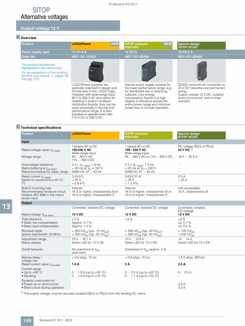
SITOPAlternative voltages
Output voltage 12 V
13/6 Siemens KT 10.1 · 2012
13
■ Overview
■ Technical specifications
1) The supply voltage must be securely isolated (SELV or PELV) from the feeding AC mains.
Product LOGO!Power SITOP compact PSU100C
Special designSITOP DC/DC
Power supply, type 12 V/1.9 A 12 V/2 A 12 V/2.5 A
Order No. 6EP1 321-1SH03 6EP1 321-5BA00 6EP1 621-2BA00
The product families are highlighted in the same color.For an explanation of the product families, see chapter 1, pages 1/8 through 1/12.
LOGO!Power supplies are optimally matched in design and functionality to the LOGO! logic modules; with wide-range input 85 V to 264 V AC and option for installing in built-in miniature distribution boards, they can be used universally in the low-end performance range. It is also possible to operate them with 110 V DC to 300 V DC.
Narrow power supply suitable for the lower performance range, e.g. for distributed use in switching cubicles. Low energy consumption thanks to a high degree of efficiency across the entire power range and minimum power loss in no-load operation.
DC/DC converter for connection to 24 V DC networks over permanent wiring. Output voltage 12 V DC, isolated, short-circuit proof, and no-load resistant.
Product LOGO!Power SITOP compact PSU100C
Special designSITOP DC/DC
Input
1-phase AC or DC 1-phase AC or DC DC voltage (SELV or PELV)Rated voltage value Vin rated 100-240 V AC
Wide-range input100 - 230 V AC Wide-range input
24 V DC 1)
Voltage range 85 ... 264 V AC110 ... 300 V DC
85 ... 264 V AC or 110 ... 300 V DC 18.5 ... 30.2 V
Overvoltage resistance 2.3 × Vin rated, 1.3 ms 2.3 x Vin rated, 1.3 ms –Mains buffering at Iout rated > 40 ms at Vin = 187 V > 20 ms at Vin = 230 V –Rated line frequency value; range 50/60 Hz; 47 ... 63 Hz 50/60 Hz; 47 ... 63 Hz –
Rated current Iin rated 0.53-0.3 0.63-0.31 A 2.5 ASwitch-on current limit (+25 °C) < 25 A < 33 A < 20 AI2t < 0.8 A2s < 1.2 A2s
Built-in incoming fuse Internal Internal (not accessible)Recommended miniature circuit breaker (IEC 898) in the mains power input
16 A or higher, characteristic B or 10 A or higher, characteristic C
16 A or higher, characteristic B or 10 A or higher, characteristic C
10 A, characteristic B
Output
Controlled, isolated DC voltage Controlled, isolated DC voltage Controlled, isolatedDC voltage
Rated voltage Vout rated 12 V DC 12 V DC 12 V DC
Total tolerance ± 3 % ± 3 % ±3 %• Static line compensation Approx. 0.1 % ca. 0.1 %• Static load compensation Approx. 1.5 % ca. 0.4 %
Residual ripple < 200 mVpp (typ. 10 mVpp) < 200 mVpp (typ. 40 mVpp) < 100 mVppSpikes (bandwidth: 20 MHz) < 300 mVpp (typ. 20 mVpp) < 300 mVpp (typ. 55 mVpp) < 200 mVpp
Adjustment range 10.5 ... 16.1 V 10.5 ... 12.9 V 12 ... 14 VStatus display Green LED for 12 V OK Green LED for 12 V OK Green LED for 12 V OK
On/off behavior No overshoot of Vout (soft start)
Overshoot of Vout approx. 5 %
Startup delay /voltage rise
< 0.5 s/typ. 10 ms < 0.6 s/typ. 10 ms < 0.5 s/typ. 300 ms
Rated current value Iout rated 1.9 A 2 A 2.5 A
Current range • Up to +60 °C 0 ... 1.9 A (up to +55 °C) 0 ... 2.0 A (up to +55 °C) 0 ... 2.5 A• Derating 0 ... 1.3 A (up to +70 °C) 0 ... 1.1 A (up to +70 °C) –
Dynamic overcurrent on • Power-up on short-circuit 3.3 A• Short circuit during operation 3.3 A
NEW NEW
KT10_EN_gesamt.book Seite 6 Mittwoch, 12. Oktober 2011 11:00 11
© Siemens AG 2011
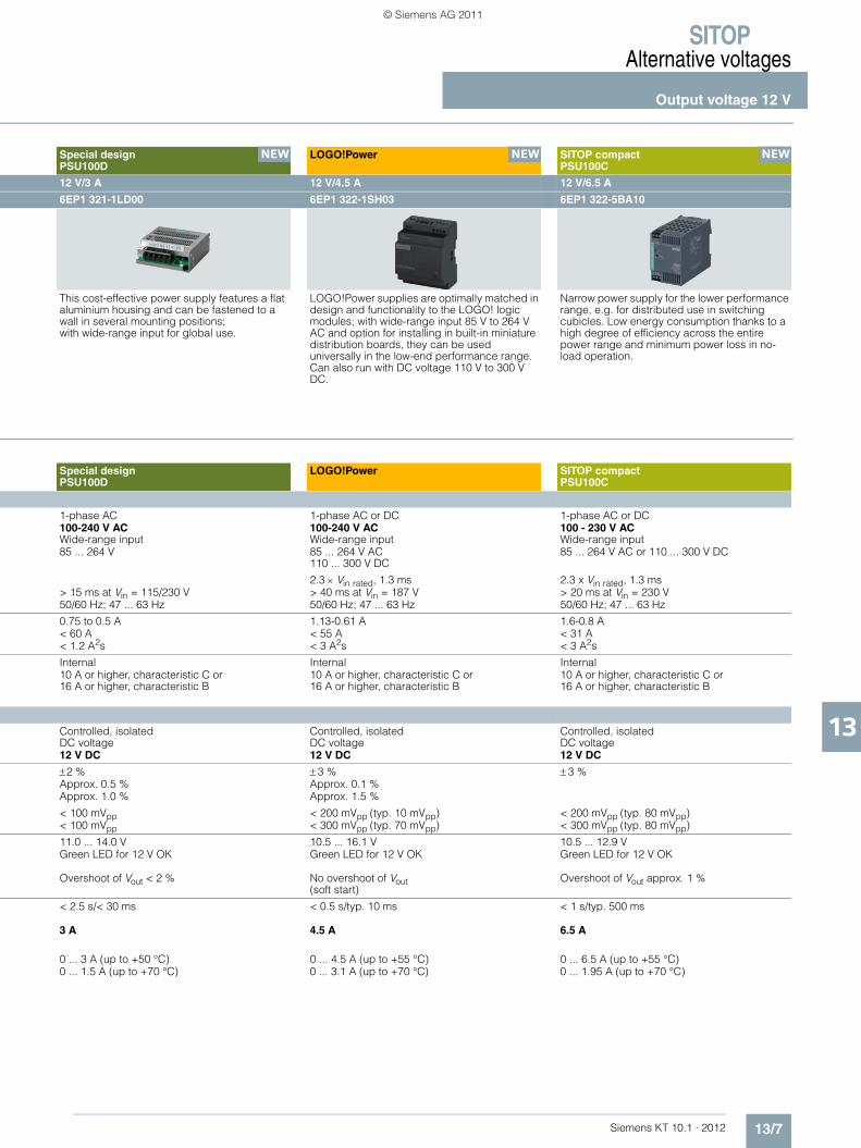
SITOPAlternative voltages
Output voltage 12 V
13/7Siemens KT 10.1 · 2012
13
Special design PSU100D
LOGO!Power SITOP compact PSU100C
12 V/3 A 12 V/4.5 A 12 V/6.5 A
6EP1 321-1LD00 6EP1 322-1SH03 6EP1 322-5BA10
This cost-effective power supply features a flat aluminium housing and can be fastened to a wall in several mounting positions; with wide-range input for global use.
LOGO!Power supplies are optimally matched in design and functionality to the LOGO! logic modules; with wide-range input 85 V to 264 V AC and option for installing in built-in miniature distribution boards, they can be used universally in the low-end performance range. Can also run with DC voltage 110 V to 300 V DC.
Narrow power supply for the lower performance range, e.g. for distributed use in switching cubicles. Low energy consumption thanks to a high degree of efficiency across the entire power range and minimum power loss in no-load operation.
Special designPSU100D
LOGO!Power SITOP compact PSU100C
1-phase AC 1-phase AC or DC 1-phase AC or DC100-240 V AC Wide-range input
100-240 V AC Wide-range input
100 - 230 V AC Wide-range input
85 ... 264 V 85 ... 264 V AC110 ... 300 V DC
85 ... 264 V AC or 110 ... 300 V DC
2.3 × Vin rated, 1.3 ms 2.3 x Vin rated, 1.3 ms > 15 ms at Vin = 115/230 V > 40 ms at Vin = 187 V > 20 ms at Vin = 230 V50/60 Hz; 47 ... 63 Hz 50/60 Hz; 47 ... 63 Hz 50/60 Hz; 47 ... 63 Hz
0.75 to 0.5 A 1.13-0.61 A 1.6-0.8 A< 60 A < 55 A < 31 A< 1.2 A2s < 3 A2s < 3 A2s
Internal Internal Internal10 A or higher, characteristic C or 16 A or higher, characteristic B
10 A or higher, characteristic C or 16 A or higher, characteristic B
10 A or higher, characteristic C or 16 A or higher, characteristic B
Controlled, isolatedDC voltage
Controlled, isolatedDC voltage
Controlled, isolatedDC voltage
12 V DC 12 V DC 12 V DC
±2 % ± 3 % ± 3 %Approx. 0.5 % Approx. 0.1 %Approx. 1.0 % Approx. 1.5 %
< 100 mVpp < 200 mVpp (typ. 10 mVpp) < 200 mVpp (typ. 80 mVpp)< 100 mVpp < 300 mVpp (typ. 70 mVpp) < 300 mVpp (typ. 80 mVpp)
11.0 ... 14.0 V 10.5 ... 16.1 V 10.5 ... 12.9 VGreen LED for 12 V OK Green LED for 12 V OK Green LED for 12 V OK
Overshoot of Vout < 2 % No overshoot of Vout (soft start)
Overshoot of Vout approx. 1 %
< 2.5 s/< 30 ms < 0.5 s/typ. 10 ms < 1 s/typ. 500 ms
3 A 4.5 A 6.5 A
0 ... 3 A (up to +50 °C) 0 ... 4.5 A (up to +55 °C) 0 ... 6.5 A (up to +55 °C)0 ... 1.5 A (up to +70 °C) 0 ... 3.1 A (up to +70 °C) 0 ... 1.95 A (up to +70 °C)
NEW NEW NEW
KT10_EN_gesamt.book Seite 7 Mittwoch, 12. Oktober 2011 11:00 11
© Siemens AG 2011

SITOPAlternative voltages
Output voltage 12 V
13/8 Siemens KT 10.1 · 2012
13
Product LOGO!Power SITOP compactPSU100C
Special designSITOP DC/DC
Power supply, type 12 V/1.9 A 12 V/2 A 12 V/2.5 A
Order No. 6EP1 321-1SH03 6EP1 321-5BA00 6EP1 621-2BA00
Output (continued)
Parallel switching for enhanced performance
Yes, 2 units Yes, 2 units Yes, 2 units
Efficiency
Efficiency at Vout rated, Iout rated ca. 80 % Approx. 82 % Approx. 83 %Power loss at Vout rated, Iout rated Approx. 5 W 5.8 W Approx. 6.1 W
Closed-loop control
Dyn. mains compensation (Vin rated ±15 %)
<0.2 % Vout <0.1 % Vout
Dynamic load compensation (Iout: 10/90/10 %)
Typ. ± 3 % Vout Typ. ± 3 % Vout
Load-step settling time • 10 at 90 % Approx. 1 ms Approx. 4 ms• 90 at 10 % Approx. 1 ms Approx. 3 ms
Protection and monitoring
Output overvoltage protection < 24 V < 24 VCurrent limitation Typically 2.8 A 2.4 A 3.0 ... 3.6 A
Short-circuit protection Constant current characteristic Electronic shutdown, automatic restart Electronic shutdown, auto restart
Sustained short-circuit rms value < 3.6 A Approx. 4.5 A Approx. 3.6 A
Overload/short-circuit indicator – – Red LED
Safety
Primary/secondary isolation Yes, SELV output Vout according to EN 60950-1 and EN 50178
Yes, SELV output Vout according to EN 60950-1 and EN 50178
Yes, safety extra low output Vout according to EN 60950-1
Protection class Class II (without protective conductor))
Class I Class II
Leakage current < 3.5 mA (typ. 0.4 mA) –Safety test Yes; CB Scheme Yes; CB Scheme YesCE mark Yes Yes Yes
UL/cUL (CSA) approval cULus-Listed (UL 508, CSA C22.2 No. 107.1), File E197259; cURus-Recognized (UL 60950, CSA C22.2 No. 60950), File E151273
cULus-Listed (UL 508, CSA C22.2 No. 107.1), File E197259; cCSAus (CSA C22.2 No. 60950-1, UL 60950-1)
cCSAus (UL 508, CSA22.2-107, UL 60950-1, CSA22.2-60950-1)
Explosion protection ATEX (EX) II 3G Ex nA IIC T3;cCSAus (CSA E60079, UL 60079), Class I, Div. 2. Group ABCD, T4
ATEX (EX) II 3G Ex nA IIC T4;cCSAus (CSA C22.2 No. 213-M1987, ANSI/ISA-12.12.01-2007) Class I, Div. 2. Group ABCD, T4
–
FM approval Class I, Div. 2. Group ABCD, T4 – –Marine approval GL, ABS GL and ABS available soon –
Degree of protection (EN 60529) IP20 IP20 IP20
EMC
Emitted interference EN 55022 Class B EN 55022 Class B EN 55022 Class BSupply harmonics limitation Not applicable Not applicable –Noise immunity EN 61000-6-2 EN 61000-3-2 EN 61000-6-2
Operating data
Permitted ambient temperature -20 ... +70 °C with natural convection
-20 ... +70 °C with natural convection 0 ... +60 °C with natural convection
Transport, storage temp range - 40 ... +85 °C -40 ... +85 °C -40 ... +85 °CHumidity class Climate class 3K3 according to
EN 60721, no condensationClimate class 3K3 according to EN 60721, no condensation
Climate class 3K3 according to EN 60721, no condensation
Mechanics
Connections
• Supply input L1, N, PE One screw-type terminal each for 0.5 ... 2.5 mm2 solid/finely stranded
Removable screw terminals, one each 0.5 ... 2.5 mm2 solid/finely stranded
One screw-type terminal each for 0.5 ... 2.5 mm2 (L+, N, PE)
• Output + 2 screw terminals for 0.5 to 2.5 mm2
One screw terminal for 0.5 ... 2.5 mm2 2 screw terminals for 0.5 to 2.5 mm2
• Output - 2 screw terminals for 0.5 to 2.5 mm2
2 screw-type terminals for 0.5 mm to 2.5 mm2
2 screw terminals for 0.5 to 2.5 mm2
Dimensions (W x H x D) in mm 54 × 90 × 55 30 x 80 x 100 32.5 × 125 × 125Weight, approx. 0.17 kg 0.17 kg 0.32 kgInstallation Snaps onto DIN rail EN 60715
35x7.5/15Snaps onto DIN rail EN 60715 35x7.5/15
Snaps onto DIN rail EN 60715 35x7.5/15
Accessories
– Removable spring-loaded terminals (6EP1971-5BA00)
–
KT10_EN_gesamt.book Seite 8 Mittwoch, 12. Oktober 2011 11:00 11
© Siemens AG 2011

SITOPAlternative voltages
Output voltage 12 V
13/9Siemens KT 10.1 · 2012
13
Special designPSU100D
LOGO!Power SITOP compact PSU100C
12 V/3 A 12 V/4.5 A 12 V/6.5 A
6EP1 321-1LD00 6EP1 322-1SH03 6EP1 322-5BA10
Yes, 2 units Yes, 2 units Yes, 2 units
Approx. 84 % Approx. 85 % Approx. 86 % Approx. 6.5 W Approx. 10 W Approx. 12.5 W
Typ. ±0.5 % Vout <0.2 % Vout
Typ. ±5 % Vout (0 to 100 %) Typ. ± 4 % Vout
Typ. 100 ms (0 to 100 %) Approx. 1 msTyp. 100 ms (0 to 100 %) Approx. 1 ms
< 17.6 V Yes, according to EN 609503.6 A Typically 5.8 A
Electronic shutdown, automatic restart Constant current characteristic Electronic shutdown, automatic restart
6 A < 7 A
– – –
Yes, SELV output voltage Vout according to EN 60950-1
Yes, SELV output voltage Vout according to EN 60950-1 and EN 50178
Yes, SELV output voltage Vout according to EN 60950-1 and EN 50178
Class I Class II (without protective conductor)) Class I
< 3.5 mA (typ. 1 mA) < 3.5 mA (typ. 0.4 mA)Yes; CB Scheme in preparation Yes; CB Scheme Yes; CB SchemeYes Yes Yes
cULus-Listed (UL 508, CSA C22.2 No. 107.1 in preparation, UL 60950-1, CSA C22.2 No. 60950-1 in preparation)
cULus-listed (UL 508, CSA C22.2 No. 107.1), File E197259; cURus-recognized (UL 60950, CSA C22.2 No. 60950), File E151273
cULus-Listed (UL 508, CSA C22.2 No. 107.1), File E197259;cCSAus (CSA C22.2 No. 60950-1, UL 60950-1)
– ATEX (EX) II 3G Ex nA IIC T3; cCSAus (CSA E60079, UL 60079),Class I, Div. 2. Group ABCD, T4
ATEX (EX) II 3G Ex nA IIC T4
– Class I, Div. 2. Group ABCD, T4 –
– GL, ABS GL and ABS available soon
IP20 IP20 IP20
EN 55022 Class B EN 55022 Class B EN 55022 Class BNot applicable Not applicable EN 61000-3-2EN 61000-6-2 EN 61000-6-2 EN 61000-3-2
-10 ... +70 °C with natural convection
-20 ... +70 °C with natural convection
-20 ... +70 °C with natural convection
-25 ... +85 °C - 40 ... +85 °C -40 ... +85 °CClimate class 3K3 according to EN 60721, no condensation
Climate class 3K3 according to EN 60721, no condensation
One screw-type terminal each for 0.3 ... 1.3 mm2 solid/finely stranded
One screw-type terminal each for 0.5 ... 2.5 mm2 solid/finely stranded
Removable screw terminals, one each0.5 ... 2.5 mm2 solid/finely stranded
1 screw terminal for 0.3 ... 1.3 mm2 2 screw terminals for 0.5 ... 2.5 mm2
1 screw terminal for 0.5 ... 2.5 mm2
1 screw terminal for 0.3 ... 1.3 mm2 2 screw terminals for0.5 ... 2.5 mm2
2 screw-type terminals for 0.5 mm to 2.5 mm2
97 x 98 x 38 72 × 90 × 55 52.5 x 80 x 100 0.37 kg 0.25 kg 0.32 kgWall mounting Snaps onto DIN rail EN 60715 35×7.5/15 Snaps onto DIN rail EN 60715 35×7.5/15
– – Removable spring-loaded terminals (6EP1971-5BA00)
KT10_EN_gesamt.book Seite 9 Mittwoch, 12. Oktober 2011 11:00 11
© Siemens AG 2011

SITOPAlternative voltages
Output voltage 12 V
13/10 Siemens KT 10.1 · 2012
13
■ Overview
■ Technical specifications
Product Special designPSU100D
Special designPSU300B
Power supply, type 12 V/8.3 A 12 V/20 A
Order No. 6EP1 322-1LD00 6EP1 424-3BA00
The low-cost power supply in flat aluminum housing can be screwed directly on a wall in various mounting positions; with wide-range input for global use.
This power supply is optimized for battery charging, it features a 3-phase wide-range input suitable for world-wide use; slim design; with switchable output characteristic, function expansion is possible in conjunction with expansion modules.
Product Special designPSU100D
Special designPSU300B
Input
1-phase AC 3-phase ACRated voltage value Vin rated 100-240 V AC Wide-range input 400-500 V 3 AC Wide-range inputVoltage range 85 ... 264 V 320 ... 575 V
Overvoltage resistance 2.3 x Vin rated, 1.3 ms Mains buffering at Iout rated > 15 ms at Vin = 115/230 V > 20 ms at Vin = 400 VRated line frequency value; range 50/60 Hz; 47 ... 63 Hz 50/60 Hz; 47 ... 63 Hz
Rated current Iin rated 2.0-1.1 A 0.7-0.6 A Switch-on current limit (+25 °C) < 75 A < 18 AI2t < 5.5 A2s < 0.8 A2s
Built-in incoming fuse Internal NoneRecommended miniature circuit breaker (IEC 898) in the mains power input
10 A or higher, characteristic C or 16 A, characteristic B
Required: 3-pole connected miniature circuit breaker 6 ... 16 A, characteristic C or circuit breaker 3RV2011-1DA10 (set to 3 A) or 3RV2711-1DD10 (UL 489)
Output
Controlled, isolated DC voltage Controlled, isolated DC voltageRated voltage Vout rated 12 V DC 12 V DC
Total tolerance ± 2 % ± 3 %• Static line compensation Approx. 0.5 % Approx. 0.2 %• Static load compensation Approx. 1.0 % Approx. 0.4 %
Residual ripple < 100 mVpp < 100 mVppSpikes (bandwidth: 20 MHz) < 100 mVpp < 200 mVpp
Adjustment range 11 ... 14 V 12 ... 14 VStatus display Green LED for 12 V O. K Green LED for 12 V OKSignaling Relay contact (NO contact, contact rating
DC 60 V/0.3 A) for 12 V OKOn/off behavior Overshoot of Vout <2 % No overshoot of Vout (soft start)
Startup delay/voltage rise < 1 s/< 30 ms < 2.5 s/< 500 msRated current value Iout rated 8.3 A 20 A
Current range • Up to + 60 °C 0 ... 8.3 A (up to +50 °C) 0 ... 20 A• Derating 0 ... 4.1 A (up to +70 °C) 20 A (up to +70 °C)
Dynamic overcurrent on • Power-up on short-circuit Approx. 22 A constant current• Short circuit during operation Typ. 60 A for 25 ms
Parallel switching for enhanced performance
Yes, 2 units Yes, 2 units (switchable characteristic)
NEW NEW
KT10_EN_gesamt.book Seite 10 Mittwoch, 12. Oktober 2011 11:00 11
© Siemens AG 2011
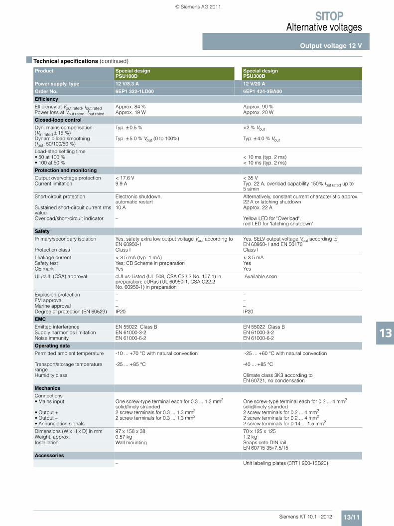
SITOPAlternative voltages
Output voltage 12 V
13/11Siemens KT 10.1 · 2012
13
■ Technical specifications (continued)
Product Special designPSU100D
Special designPSU300B
Power supply, type 12 V/8.3 A 12 V/20 A
Order No. 6EP1 322-1LD00 6EP1 424-3BA00
Efficiency
Efficiency at Vout rated, Iout rated Approx. 84 % Approx. 90 %Power loss at Vout rated, Iout rated Approx. 19 W Approx. 20 W
Closed-loop control
Dyn. mains compensation (Vin rated ± 15 %)
Typ. ± 0.5 % <2 % Vout
Dynamic load smoothing(Iout: 50/100/50 %)
Typ. ± 5.0 % Vout (0 to 100%) Typ. ± 4.0 % Vout
Load-step settling time• 50 at 100 % < 10 ms (typ. 2 ms)• 100 at 50 % < 10 ms (typ. 2 ms)
Protection and monitoring
Output overvoltage protection < 17.6 V < 35 VCurrent limitation 9.9 A Typ. 22 A, overload capability 150% Iout rated up to
5 s/min
Short-circuit protection Electronic shutdown, automatic restart
Alternatively, constant current characteristic approx. 22 A or latching shutdown
Sustained short-circuit current rms value
10 A Approx. 22 A
Overload/short-circuit indicator – Yellow LED for "Overload", red LED for "latching shutdown"
Safety
Primary/secondary isolation Yes, safety extra low output voltage Vout according to EN 60950-1
Yes, SELV output voltage Vout according to EN 60950-1 and EN 50178
Protection class Class I Class I
Leakage current < 3.5 mA (typ. 1 mA) < 3.5 mASafety test Yes; CB Scheme in preparation YesCE mark Yes Yes
UL/cUL (CSA) approval cULus-Listed (UL 508, CSA C22.2 No. 107.1) in preparation; cURus (UL 60950-1, CSA C22.2 No. 60950-1) in preparation
Available soon
Explosion protection – –FM approval – –Marine approval – –Degree of protection (EN 60529) IP20 IP20
EMC
Emitted interference EN 55022 Class B EN 55022 Class BSupply harmonics limitation EN 61000-3-2 EN 61000-3-2Noise immunity EN 61000-6-2 EN 61000-6-2
Operating data
Permitted ambient temperature -10 ... +70 °C with natural convection -25 ... +60 °C with natural convection
Transport/storage temperature range
-25 ... +85 °C -40 ... +85 °C
Humidity class Climate class 3K3 according to EN 60721, no condensation
Mechanics
Connections • Mains input One screw-type terminal each for 0.3 ... 1.3 mm2
solid/finely strandedOne screw-type terminal each for 0.2 ... 4 mm2 solid/finely stranded
• Output + 2 screw terminals for 0.3 ... 1.3 mm2 2 screw terminals for 0.2 ... 4 mm2
• Output – 2 screw terminals for 0.3 ... 1.3 mm2 2 screw terminals for 0.2 ... 4 mm2
• Annunciation signals 2 screw terminals for 0.14 ... 1.5 mm2
Dimensions (W x H x D) in mm 97 x 158 x 38 70 x 125 x 125Weight, approx. 0.57 kg 1.2 kgInstallation Wall mounting Snaps onto DIN rail
EN 60715 35×7.5/15
Accessories
– Unit labeling plates (3RT1 900-1SB20)
KT10_EN_gesamt.book Seite 11 Mittwoch, 12. Oktober 2011 11:00 11
© Siemens AG 2011

SITOPAlternative voltages
Output voltage 15 V
13/12 Siemens KT 10.1 · 2012
13
■ Overview
■ Technical specifications
Product LOGO!Power LOGO!Power Special designSITOP dual
Power supply, type 15 V/1.9 A 15 V/4 A 2 x 15 V/3.5 A
Order No. 6EP1 351-1SH03 6EP1 352-1SH03 6EP1 353-0AA00
The product families are highlighted in the same color.For an explanation of the product families, see chapter 1, pages 1/8 through 1/12.
The power supplies of the LOGO!Power range are optimally matched to the LOGO! logic modules in their functionality and design; with the wide-range input 85 V to 264 V AC and option for installing in built-in miniature distribution boards, they can be used universally in the low-end performance range. They can also operate with DC 110 V to 300 V.
The industrial power supply with two 15 V outputs that can be switched in parallel and in series; can be used, for example, to supply electronic loads with ±15 V.
Product LOGO!Power LOGO!Power Special designSITOP dual
Input
1-phase AC or DC 1-phase AC or DC 1-phase ACRated voltage value Vin rated 100-240 V AC
Wide-range input100-240 V AC Wide-range input
120-230 V AC Wide-range input
Voltage range AC 85 ... 264 VDC 110 ... 300 V
AC 85 ... 264 VDC 110 ... 300 V
93 ... 264 V
Overvoltage resistance 2.3 × Vin rated, 1.3 ms 2.3 × Vin rated, 1.3 ms Surge voltage in accordance with EN 61000-6-2 Table 4
Mains buffering at Iout rated > 40 ms at Vin = 187 V > 40 ms at Vin = 187 V > 10/40 ms at Vin = 120/187 V Rated line frequency value; range 50/60 Hz; 47 ... 63 Hz 50/60 Hz; 47 ... 63 Hz 50/60 Hz; 47 ... 63 Hz
Rated current Iin rated 0.63-0.33 A 1.24-0.68 A 1.9-1.15 ASwitch-on current limit (+25 °C) < 25 A < 55 A < 30 A, typ. 3 msI2t < 0.8 A2s < 3 A2s < 3 A2s
Built-in incoming fuse Internal Internal T4 A/250 V (not accessible)Recommended miniature circuit breaker (IEC 898) in the mains power input
16 A or higher, characteristic B or 10 A or higher, characteristic C
16 A or higher, characteristic B or 10 A or higher, characteristic C
16 A or higher, characteristic B or 10 A or higher, characteristic C
Output
Controlled, isolated DC voltage Controlled, isolated DC voltage Controlled, isolatedDC voltage
Rated voltage Vout rated 15 V DC 15 V DC 2 × 15 V DC
Total tolerance ± 3 % ± 3 % ± 2 %• Static line compensation Approx. 0.1 % Approx. 0.1 % ca. 0.2 %• Static load compensation Approx. 1.5 % Approx. 1.5 % ca. 0.2 %
Residual ripple < 200 mVpp (typ. 10 mVpp) < 200 mVpp (typ. 10 mVpp) < 50 mVpp (typ. 20 mVpp)Spikes (bandwidth: 20 MHz) < 300 mVpp (typ. 30 mVpp) < 300 mVpp (typ. 70 mVpp) < 150 mVpp
Adjustment range 10.5 ... 16.1 V 10.5 ... 16.1 V 14.5 ... 17 V Status display Green LED for 15 V OK Green LED for 15 V OK Green LED for Vout >10 V
(summation display)Signaling –On/off behavior No overshoot of Vout
(soft start)No overshoot of Vout (soft start)
Overshoot of Vout < 3 %
Startup delay /voltage rise
< 0.5 s/typ. 15 ms < 0.5 s/typ. 15 ms < 1 s/–
Rated current value Iout rated 1.9 A 4 A 2 × 3.5 A
Current range • Up to +60 °C 0 ... 1.9 A (up to +55 °C) 0 ... 4 A (up to +55 °C) 2 × 0 ... 2.5 A • Derating 0 ... 1.3 A (up to +70 °C) 0 ... 2.8 A (up to +70 °C) 2 × 0 ... 3.5 A (up to +45 °C)
Dynamic overcurrent on • Power-up on short-circuit –• Short circuit during operation –
Parallel switching for enhanced performance
Yes, 2 units Yes, 2 units Yes, 2 units
NEW NEW
KT10_EN_gesamt.book Seite 12 Mittwoch, 12. Oktober 2011 11:00 11
© Siemens AG 2011

SITOPAlternative voltages
Output voltage 15 V
13/13Siemens KT 10.1 · 2012
13
■ Technical specifications (continued)
Product LOGO!Power LOGO!Power Special designSITOP dual
Power supply, type 15 V/1.9 A 15 V/4 A 2 x 15 V/3.5 A
Order No. 6EP1 351-1SH03 6EP1 352-1SH03 6EP1 353-0AA00
Efficiency
Efficiency at Vout rated, Iout rated Approx. 81 % Approx. 85 % Approx. 80 %Power loss at Vout rated, Iout rated Approx. 7 W Approx. 11 W Approx. 27 W
Closed-loop control
Dyn. mains compensation (Vin rated ±15 %)
<0.2 % Vout <0.2 % Vout
Dynamic load compensation (Iout: 10/90/10 %)
Typ. ± 2.8 % Vout Typ. ± 3 % Vout
Load-step settling time• 10 at 90 % Typ. 1 ms Typ. 1 ms• 90 at 10 % Typ. 1 ms Typ. 1 ms
Protection and monitoring
Output overvoltage protection Yes, according to EN 60950Current limitation Typically 2.7 A Typically 5.7 A Limit point < 4.9 A;
switch-off point < 6 A
Short-circuit protection Constant current characteristic Constant current characteristic Electronic shutdown, automatic restart
Sustained short-circuit current rms value
< 3.6 A < 7 A –
Overload/short-circuit indicator – – –
Safety
Primary/secondary isolation Yes, SELV output voltage Vout according to EN 60950-1 and EN 50178
Yes, SELV output voltage Vout according to EN 60950-1 and EN 50178
Yes, safety extra low output voltage Vout according to EN 60950-1
Protection class Class II (without protective conductor)
Class II (without protective conductor)
Class I
Leakage current < 3.5 mASafety test Yes; CB Scheme Yes; CB Scheme YesCE mark Yes Yes Yes
UL/cUL (CSA) approval cULus-Listed (UL 508, CSA C22.2 No. 107.1), File E197259; cURus-Recognized (UL 60950, CSA C22.2 No. 60950), File E151273
cULus-Listed (UL 508, CSA C22.2 No. 107.1), File E197259; cURus-Recognized (UL 60950, CSA C22.2 No. 60950), File E151273
cULus-listed (UL 508, CSA C22.2 No. 142), File E179336
Explosion protection ATEX (EX) II 3G Ex nA IIC T3; cCSAus (CSA E60079, UL 60079), Class I, Div. 2. Group ABCD, T4
ATEX (EX) II 3G Ex nA IIC T3; cCSAus (CSA E60079, UL 60079), Class I, Div. 2. Group ABCD, T4
–
FM approval Class I, Div. 2. Group ABCD, T4 Class I, Div. 2. Group ABCD, T4 –Marine approval GL GL –
Degree of protection (EN 60529) IP20 IP20 IP20
EMC
Emitted interference EN 55022 Class B EN 55022 Class B EN 55011 Class ASupply harmonics limitation Not applicable Not applicable –Noise immunity EN 61000-6-2 EN 61000-6-2 EN 61000-6-2
Operating data
Permitted ambient temperature -20 ... +70 °C with natural convection
-20 ... +70 °C with natural convection
0 ... +60 °C with natural convection, derated above +45 °C
Transport/storage temperature range
-40 ... +85 °C - 40 ... +85 °C -40 ... +70 °C
Humidity class Climate class 3K3 according to EN 60721, no condensation
Climate class 3K3 according to EN 60721, no condensation
Climate class 3K3 according to EN 60721, no condensation
Mechanics
Connections
• Supply input L1, N, PE One screw-type terminal each for 0.5 ... 2.5 mm2 solid/finely stranded
One screw-type terminal each for 0.5 ... 2.5 mm2 solid/finely stranded
One screw-type terminal each for 0.5 ... 2.5 mm2 solid/finely stranded
• Output + 2 screw terminals for 0.5 to 2.5 mm2
2 screw terminals for 0.5 to 2.5 mm2
1 screw terminal each for 0.5 ... 2.5 mm2 (P15_1, GND1, GDN2)
• Output - 2 screw terminals for 0.5 to 2.5 mm2
2 screw terminals for 0.5 to 2.5 mm2
2 screw terminals for 0.5 ... 2.5 mm2 (P15_2)
Dimensions (W x H x D) in mm 54 × 90 × 55 72 × 90 × 55 75 × 125 × 125Weight, approx. 0.17 kg 0.25 kg 0.75 kgInstallation Snaps onto DIN rail EN 60715
35x7.5/15Snaps onto DIN rail EN 60715 35x7.5/15
Snaps onto DIN rail EN 60715 35x7.5/15
KT10_EN_gesamt.book Seite 13 Mittwoch, 12. Oktober 2011 11:00 11
© Siemens AG 2011
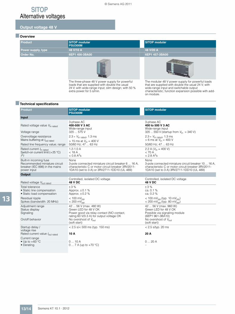
SITOPAlternative voltages
Output voltage 48 V
13/14 Siemens KT 10.1 · 2012
13
■ Overview
■ Technical specifications
Product SITOP modularPSU300M
SITOP modular
Power supply, type 48 V/10 A 48 V/20 A
Order No. 6EP1 456-3BA00 6EP1 457-3BA00
The three-phase 48 V power supply for powerful loads that are supplied with double the usual 24 V; with wide-range input; slim design; with 50 % extra power for 5 s/min.
The modular 48 V power supply for powerful loads that are supplied with double the usual 24 V; with wide-range input and switchable output characteristic; function expansion possible with add-on module.
Product SITOP modularPSU300M
SITOP modular
Input
3-phase AC 3-phase ACRated voltage value Vin rated 400-500 V 3 AC
Wide-range input400 to 500 V 3 AC Wide-range input
Voltage range 320 ... 575 V 320 ... 550 V (startup from Vin > 340 V)
Overvoltage resistance 2.3 × Vin rated, 1.3 ms 2.3 × Vin rated, 1.3 ms Mains buffering at Iout rated > 15 ms at Vin = 400 V > 6 ms at Vin = 400 V
Rated line frequency value; range 50/60 Hz; 47 ... 63 Hz 50/60 Hz; 47 ... 63 Hz
Rated current Iin rated 1.2-1.0 A 2.2 A (Vin = 400 V)Switch-on current limit (+25 °C) < 18 A < 70 AI2t < 0.8 A2s < 2.8 A2s
Built-in incoming fuse None NoneRecommended miniature circuit breaker (IEC 898) in the mains power input
3-pole connected miniature circuit breaker 6 ... 16 A, characteristic C or motor circuit breaker 3RV2011-1DA10 (set to 3 A) or 3RV2711-1DD10 (UL 489)
3-pole connected miniature circuit breaker 10 ... 16 A, characteristic C or motor circuit breaker 3RV2011-1DA10 (set to 3 A) 3RV2711-1DD10 (UL 489)
Output
Controlled, isolated DC voltage Controlled, isolated DC voltageRated voltage Vout rated 48 V DC 48 V DC
Total tolerance ± 3 % ± 3 %• Static line compensation Approx. ± 0.1 % ca. 0.1 %• Static load compensation Approx. ± 0.2 % ca. 0.2 %
Residual ripple < 100 mVpp < 100 mVpp (typ. 10 mVpp)Spikes (bandwidth: 20 MHz) < 200 mVpp < 200 mVpp (typ. 80 mVpp)
Adjustment range 42 ... 56 V (max. 480 W) 42 ... 56 V (max. 960 W)Status display Green LED for 48 V OK Green LED for 48 V OKSignaling Power good via relay contact (NO contact,
rating 60 V/0.3 A) for output voltage OKPossible via signaling module (6EP1 961-3BA10)
On/off behavior No overshoot of Vout (soft start)
No overshoot of Vout (soft start)
Startup delay /voltage rise
< 2.5 s/< 500 ms (typ. 150 ms) < 2.5 s/typ. 20 ms
Rated current value Iout rated 10 A 20 A
Current range • Up to +60 °C 0 ... 10 A 0 ... 20 A• Derating 0 ... 7 A (up to +70 °C) –
KT10_EN_gesamt.book Seite 14 Mittwoch, 12. Oktober 2011 11:00 11
© Siemens AG 2011

SITOPAlternative voltages
Output voltage 48 V
13/15Siemens KT 10.1 · 2012
13
■ Technical specifications (continued)
Product SITOP modularPSU300M
SITOP modular
Power supply, type 48 V/10 A 48 V/20 A
Order No. 6EP1 456-3BA00 6EP1 457-3BA00
Output (continued)
Dynamic overcurrent on • Power-up on short-circuit Constant current approx. 11 A Constant current approx. 23 A• Short circuit during operation Typ. 23 A for 25 ms Typ. 60 A for 25 ms
Parallel switching for enhanced performance
Yes, 2 units (switchable characteristic) Yes, 2 units (switchable characteristic)
Efficiency
Efficiency at Vout rated, Iout rated Approx. 93 % Approx. 90 %Power loss at Vout rated, Iout rated Approx. 36 W Approx. 106 W
Protection and monitoring
Output overvoltage protection Yes, according to EN 60950 Yes, according to EN 60950Current limitation Typ. 11 A, overload capability 150% Iout rated up to
5 s/minTypically 23 A
Short-circuit protection Alternatively, constant current characteristic approx. 11 A or latching shutdown
Alternatively, constant current characteristic approx. 23 A or latching shutdown
Sustained short-circuit current rms value
Approx. 11 A Approx. 23 A
Overload/short-circuit indicator LED yellow for "overload", LED red for "latching shutdown"
LED yellow for "overload", LED red for "latching shutdown"
Safety
Primary/secondary isolation Yes, SELV output voltage Vout according to EN 60950-1 and EN 50178
Yes, safety extra low output voltage Vout according to EN 60950-1
Protection class Class I Class I
Leakage current < 3.5 mA < 3.5 mA (typ. 0.68 mA)Safety test Yes YesCE mark Yes Yes
UL/cUL (CSA) approval cULus-listed (UL 508, CSA C22.2 No. 107.1), File E197259
cULus-Listed (UL 508, CSA C22.2 No. 107.1), File E197259; cCSAus (CSA C22.2 No. 60950, UL 60950)
Explosion protection ATEX (available soon) –Marine approval GL and ABS available soon –
Degree of protection (EN 60529) IP20 IP20
EMC
Emitted interference EN 55022 Class B EN 55022 Class BSupply harmonics limitation EN 61000-3-2 EN 61000-3-2Noise immunity EN 61000-6-2 EN 61000-6-2
Operating data
Permitted ambient temperature -10 ... +70 °C with natural convection 0 ... +60 °C with natural convectionTransport/storage temperature range
-40 ... +85 °C -40 ... +85 °C
Humidity class Climate class 3K3 according to EN 60721,no condensation
Climate class 3K3 according to EN 60721, no condensation
Mechanics
Connections
• Supply input L1, L2. L3.PE One screw-type terminal each for 0.5 ... 2.5 mm2 solid/finely stranded
One screw-type terminal each for 0.2 ... 4 mm2 solid/finely stranded
• Output + One screw terminal each for 0.2 ... 4 mm2 2 screw terminals each for 0.33 ... 10 mm2
• Output - One screw terminal each for 0.2 ... 4 mm2 2 screw terminals each for 0.33 ... 10 mm2
• Alarm signals 2 screw terminals for 0.14 ... 1.5 mm2 –
Dimensions (W x H x D) in mm 70 x 125 x 125 240 × 125 × 125Weight, approx. 1.2 kg 3.2 kgInstallation Snaps onto DIN rail EN 60715 35×7.5/15 Snaps onto DIN rail EN 60715 35×15
Accessories
Device labeling plates (3RT1900-1SB20) Signaling module (6EP1961-3BA10)
KT10_EN_gesamt.book Seite 15 Mittwoch, 12. Oktober 2011 11:00 11
© Siemens AG 2011

SITOPAlternative voltages
Ordering data and additional information
13/16 Siemens KT 10.1 · 2012
13
■ Selection and ordering data
Product Input Output Order No. Price
Voltage Vin rated Voltage Vout rated Current Iout rated
Special design, SITOP flexi
120/230 V AC DC 3-52 V 2-10 A 6EP1 353-2BA00
LOGO!Power
100-240 V AC 5 V DC 3 A 6EP1 311-1SH03
LOGO!Power
100-240 V AC 5 V DC 6.3 A 6EP1 311-1SH13
LOGO!Power
100-240 V AC 12 V DC 1.9 A 6EP1 321-1SH03
SITOP compact, PSU100C
100 - 230 V AC 12 V DC 2 A 6EP1 321-5BA00
Special design, SITOP DC/DC
24 V DC 12 V DC 2.5 A 6EP1 621-2BA00
Special design, PSU100D(Planned delivery date: December 2011)
100-240 V AC 12 V DC 3 A 6EP1 321-1LD00
LOGO!Power
100-240 V AC 12 V DC 4.5 A 6EP1 322-1SH03
NEW
NEW
NEW
NEW
NEW
NEW
KT10_EN_gesamt.book Seite 16 Mittwoch, 12. Oktober 2011 11:00 11
© Siemens AG 2011
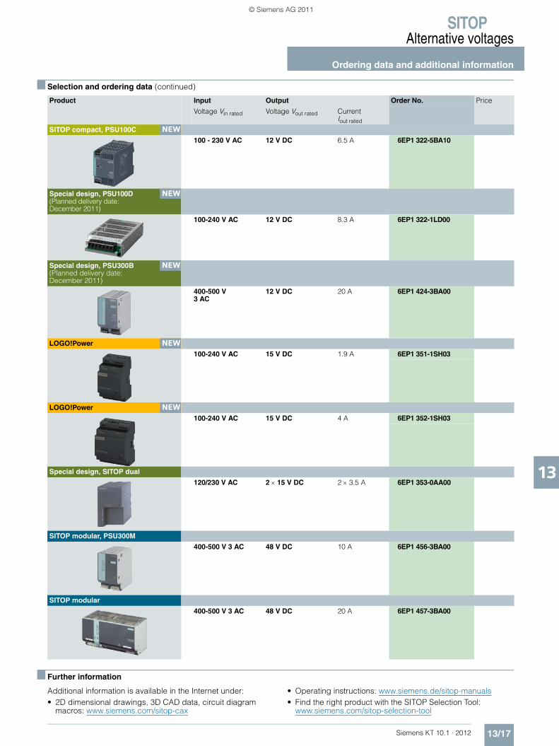
SITOPAlternative voltages
Ordering data and additional information
13/17Siemens KT 10.1 · 2012
13
■ Selection and ordering data (continued)
■ Further information
Additional information is available in the Internet under:• 2D dimensional drawings, 3D CAD data, circuit diagram
macros: www.siemens.com/sitop-cax
• Operating instructions: www.siemens.de/sitop-manuals• Find the right product with the SITOP Selection Tool:
www.siemens.com/sitop-selection-tool
Product Input Output Order No. Price
Voltage Vin rated Voltage Vout rated Current Iout rated
SITOP compact, PSU100C
100 - 230 V AC 12 V DC 6.5 A 6EP1 322-5BA10
Special design, PSU100D(Planned delivery date: December 2011)
100-240 V AC 12 V DC 8.3 A 6EP1 322-1LD00
Special design, PSU300B(Planned delivery date: December 2011)
400-500 V 3 AC
12 V DC 20 A 6EP1 424-3BA00
LOGO!Power
100-240 V AC 15 V DC 1.9 A 6EP1 351-1SH03
LOGO!Power
100-240 V AC 15 V DC 4 A 6EP1 352-1SH03
Special design, SITOP dual
120/230 V AC 2 × 15 V DC 2 × 3.5 A 6EP1 353-0AA00
SITOP modular, PSU300M
400-500 V 3 AC 48 V DC 10 A 6EP1 456-3BA00
SITOP modular
400-500 V 3 AC 48 V DC 20 A 6EP1 457-3BA00
NEW
NEW
NEW
NEW
NEW
KT10_EN_gesamt.book Seite 17 Mittwoch, 12. Oktober 2011 11:00 11
© Siemens AG 2011

SITOP
Notes
13/18 Siemens KT 10.1 · 2012
13
KT10_EN_gesamt.book Seite 18 Mittwoch, 12. Oktober 2011 11:00 11
© Siemens AG 2011

Siemens KT 10.1 · 2012
1414/2 Mounting bracket14/2 Mounting adapter for DIN rail14/2 Connector for devices in IP65 and IP6714/2 Device labeling plates14/2 Ordering data and additional information
Accessories
Export regulations AL and ECCNsee page 17/9
KT10_EN_gesamt.book Seite 1 Mittwoch, 12. Oktober 2011 11:00 11
© Siemens AG 2011
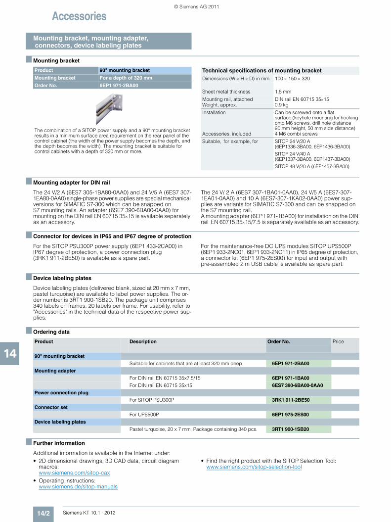
Accessories
Mounting bracket, mounting adapter, connectors, device labeling plates
14/2 Siemens KT 10.1 · 2012
14
■ Mounting bracket
■ Mounting adapter for DIN rail
The 24 V/2 A (6ES7 305-1BA80-0AA0) and 24 V/5 A (6ES7 307-1EA80-0AA0) single-phase power supplies are special mechanical versions for SIMATIC S7-300 which can be snapped on S7 mounting rails. An adapter (6SE7 390-6BA00-0AA0) for mounting on the DIN rail EN 60715 35×15 is available separately as an accessory.
The 24 V/ 2 A (6ES7 307-1BA01-0AA0), 24 V/5 A (6ES7-307-1EA01-0AA0) and 10 A (6ES7-307-1KA02-0AA0) power sup-plies are variants for SIMATIC S7-300 and can be snapped on the S7 mounting rail. A mounting adapter (6EP1 971-1BA00) for installation on the DIN rail EN 60715 35×15/7.5 is separately available as an accessory.
■ Connector for devices in IP65 and IP67 degree of protection
For the SITOP PSU300P power supply (6EP1 433-2CA00) in IP67 degree of protection, a power connection plug (3RK1 911-2BE50) is available as a spare part.
For the maintenance-free DC UPS modules SITOP UPS500P (6EP1 933-2NC01, 6EP1 933-2NC11) in IP65 degree of protection, a connector kit (6EP1 975-2ES00) for input and output with pre-assembled 2 m USB cable is available as spare part.
■ Device labeling plates
Device labeling plates (delivered blank, sized at 20 mm x 7 mm, pastel turquoise) are available to label power supplies. The or-der number is 3RT1 900-1SB20. The package unit comprises 340 labels on frames, 20 labels per frame. For usability, refer to "Accessories" in the technical data of the respective power sup-plies.
■ Ordering data
■ Further information
Additional information is available in the Internet under:• 2D dimensional drawings, 3D CAD data, circuit diagram
macros: www.siemens.com/sitop-cax
• Operating instructions:www.siemens.de/sitop-manuals
• Find the right product with the SITOP Selection Tool: www.siemens.com/sitop-selection-tool
Product 90° mounting bracket
Mounting bracket For a depth of 320 mm
Order No. 6EP1 971-2BA00
The combination of a SITOP power supply and a 90° mounting bracket results in a minimum surface area requirement on the rear panel of the control cabinet (the width of the power supply becomes the depth, and the depth becomes the width). The mounting bracket is suitable for control cabinets with a depth of 320 mm or more.
Technical specifications of mounting bracketDimensions (W × H × D) in mm 100 × 150 × 320
Sheet metal thickness 1.5 mm
Mounting rail, attached DIN rail EN 60715 35×15Weight, approx. 0.9 kg
Installation Can be screwed onto a flat surface (keyhole mounting for hooking onto M6 screws, drill hole distance 90 mm height, 50 mm side distance)
Accessories, included 4 M6 combi screws
Suitable, for example, for SITOP 24 V/20 A (6EP1336-3BA00, 6EP1436-3BA00)SITOP 24 V/40 A(6EP1337-3BA00, 6EP1437-3BA00)SITOP 48 V/20 A (6EP1457-3BA00)
Product Description Order No. Price
90° mounting bracketSuitable for cabinets that are at least 320 mm deep 6EP1 971-2BA00
Mounting adapter For DIN rail EN 60715 35x7.5/15 6EP1 971-1BA00For DIN rail EN 60715 35x15 6ES7 390-6BA00-0AA0
Power connection plugFor SITOP PSU300P 3RK1 911-2BE50
Connector setFor UPS500P 6EP1 975-2ES00
Device labeling platesPastel turquoise, 20 x 7 mm; Package containing 340 pcs. 3RT1 900-1SB20
KT10_EN_gesamt.book Seite 2 Mittwoch, 12. Oktober 2011 11:00 11
© Siemens AG 2011
Siemens KT 10.1 · 2012
1515/2 Overview15/2 Technical specfications15/3 Selection and ordering data
SIPLUS power supplies
Export regulations AL and ECCNsee page 17/9
KT10_EN_gesamt.book Seite 1 Mittwoch, 12. Oktober 2011 11:00 11
© Siemens AG 2011
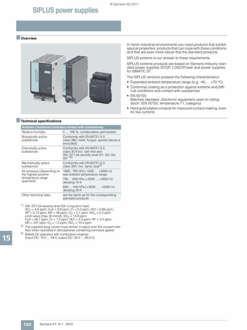
SIPLUS power supplies
15/2 Siemens KT 10.1 · 2012
15
■ Overview
In harsh industrial environments you need products that exhibit special properties, products that can cope with these conditions and that are even more robust that the standard products.
SIPLUS extreme is our answer to these requirements.
SIPLUS extreme products are based on Siemens Industry stan-dard power supplies SITOP, LOGO!Power and power supplies for SIMATIC S7.
The SIPLUS versions possess the following characteristics:• Expanded ambient temperature range (e.g. -40 … +70 °C) • Conformal coating as a protection against extreme and diffi-
cult conditions and contact with substances• EN 50155:
Matches standard „Electronic equipment used on rolling stock“ (EN 50155, temperature T1, category)
• Hard gold-plated contacts for improved contact-making, even for low currents
■ Technical specifications
1) ISA -S71.04 severity level GX: Long-term load: SO2 < 4.8 ppm; H2S < 9.9 ppm; Cl < 0.2 ppm; HCl < 0.66 ppm; HF < 0.12 ppm; NH < 49 ppm; O3 < 0.1 ppm; NOx < 5.2 ppm Limit value (max 30 min/d): SO2 < 14.8 ppm; H2S < 49.7 ppm; Cl < 1.0 ppm; HCl < 3.3 ppm; HF < 2.4 ppm; NH < 247 ppm; O3 < 1.0 ppm; NOx < 10.4 ppm
2) The supplied plug covers must remain in place over the unused inter-face when operated in atmospheres containing corrosive gases!
3) Ballast for operation with combustion engines (Input DC: 10.5 ... 59 V, output DC: 20.4 ... 28.8 V).
Ambient conditions (includes contact with substances)
Relative humidity 5 … 100 %, condensation permissible
Biologically active substances
Conformity with EN 60721-3-3, class 3B2: mold, fungus, spores (fauna is excluded)
Chemically active substances
Conformity with EN 60721-3-3, class 3C4 incl. salt mist and ISA -S71.04 severity level G1; G2; G3; GX 1)2)
Mechanically active substances
Conformity with EN 60721-3-3, class 3S4, incl. sand, dust2)
Air pressure (depending on the highest positive temperature range specified)
1080...795 hPa (-1000 … +2000 m) see ambient temperature range795 ... 658 hPa (+2000 ... +3500 m)derating 10 K658 … 540 hPa (+3500 … +5000 m) derating 20 K
Other technical data are the same as for the corresponding standard products
KT10_EN_gesamt.book Seite 2 Mittwoch, 12. Oktober 2011 11:00 11
© Siemens AG 2011
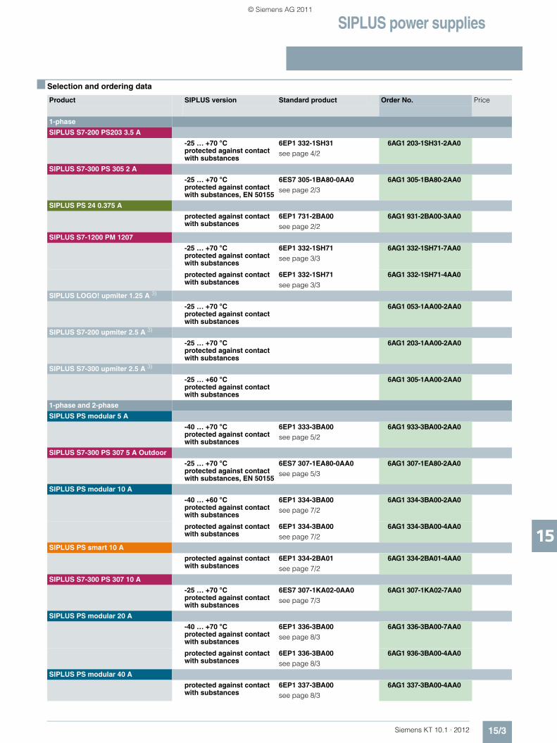
SIPLUS power supplies
15/3Siemens KT 10.1 · 2012
15
■ Selection and ordering data
Product SIPLUS version Standard product Order No. Price
1-phase
SIPLUS S7-200 PS203 3.5 A
-25 … +70 °Cprotected against contact with substances
6EP1 332-1SH31 see page 4/2
6AG1 203-1SH31-2AA0
SIPLUS S7-300 PS 305 2 A
-25 … +70 °Cprotected against contact with substances, EN 50155
6ES7 305-1BA80-0AA0see page 2/3
6AG1 305-1BA80-2AA0
SIPLUS PS 24 0.375 A
protected against contact with substances
6EP1 731-2BA00see page 2/2
6AG1 931-2BA00-3AA0
SIPLUS S7-1200 PM 1207
-25 … +70 °Cprotected against contact with substances
6EP1 332-1SH71see page 3/3
6AG1 332-1SH71-7AA0
protected against contact with substances
6EP1 332-1SH71see page 3/3
6AG1 332-1SH71-4AA0
SIPLUS LOGO! upmiter 1.25 A 3)
-25 … +70 °Cprotected against contact with substances
6AG1 053-1AA00-2AA0
SIPLUS S7-200 upmiter 2.5 A 3)
-25 … +70 °Cprotected against contact with substances
6AG1 203-1AA00-2AA0
SIPLUS S7-300 upmiter 2.5 A 3)
-25 … +60 °Cprotected against contact with substances
6AG1 305-1AA00-2AA0
1-phase and 2-phase
SIPLUS PS modular 5 A
-40 … +70 °Cprotected against contact with substances
6EP1 333-3BA00see page 5/2
6AG1 933-3BA00-2AA0
SIPLUS S7-300 PS 307 5 A Outdoor
-25 … +70 °Cprotected against contact with substances, EN 50155
6ES7 307-1EA80-0AA0see page 5/3
6AG1 307-1EA80-2AA0
SIPLUS PS modular 10 A
-40 … +60 °Cprotected against contact with substances
6EP1 334-3BA00see page 7/2
6AG1 334-3BA00-2AA0
protected against contact with substances
6EP1 334-3BA00see page 7/2
6AG1 334-3BA00-4AA0
SIPLUS PS smart 10 A
protected against contact with substances
6EP1 334-2BA01see page 7/2
6AG1 334-2BA01-4AA0
SIPLUS S7-300 PS 307 10 A
-25 … +70 °Cprotected against contact with substances
6ES7 307-1KA02-0AA0see page 7/3
6AG1 307-1KA02-7AA0
SIPLUS PS modular 20 A
-40 … +70 °Cprotected against contact with substances
6EP1 336-3BA00see page 8/3
6AG1 336-3BA00-7AA0
protected against contact with substances
6EP1 336-3BA00see page 8/3
6AG1 936-3BA00-4AA0
SIPLUS PS modular 40 A
protected against contact with substances
6EP1 337-3BA00see page 8/3
6AG1 337-3BA00-4AA0
KT10_EN_gesamt.book Seite 3 Mittwoch, 12. Oktober 2011 11:00 11
© Siemens AG 2011
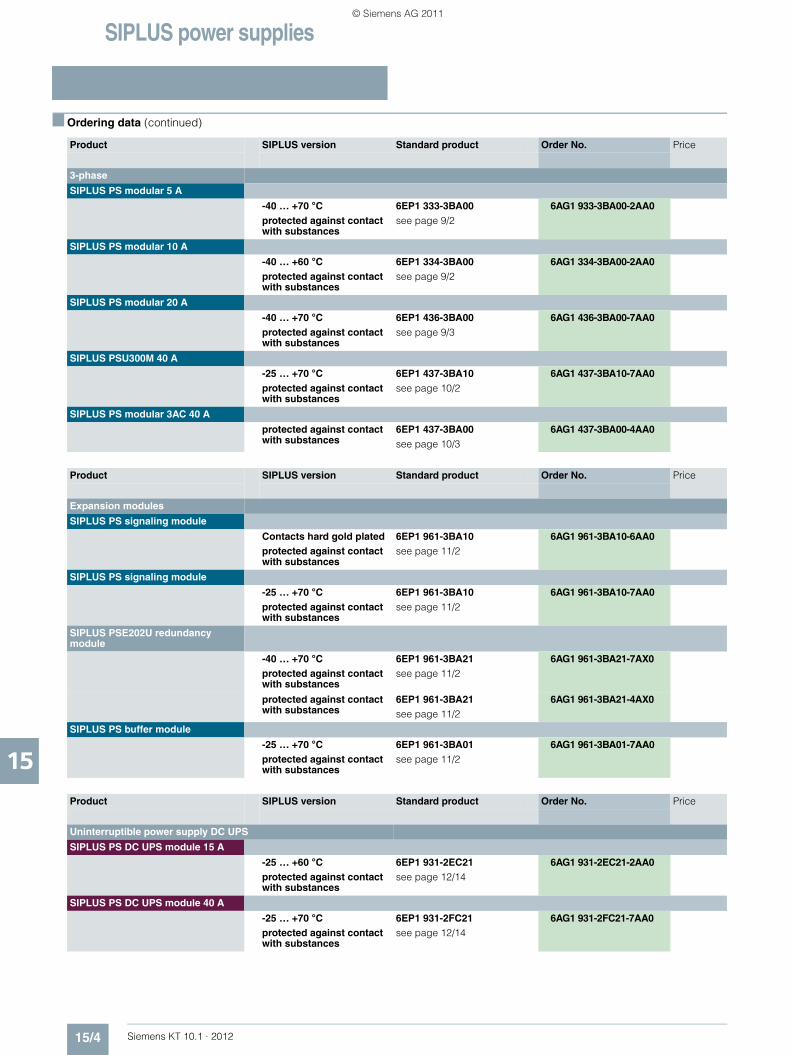
SIPLUS power supplies
15/4 Siemens KT 10.1 · 2012
15
■ Ordering data (continued)
Product SIPLUS version Standard product Order No. Price
3-phase
SIPLUS PS modular 5 A
-40 … +70 °Cprotected against contact with substances
6EP1 333-3BA00 see page 9/2
6AG1 933-3BA00-2AA0
SIPLUS PS modular 10 A
-40 … +60 °Cprotected against contact with substances
6EP1 334-3BA00see page 9/2
6AG1 334-3BA00-2AA0
SIPLUS PS modular 20 A
-40 … +70 °Cprotected against contact with substances
6EP1 436-3BA00see page 9/3
6AG1 436-3BA00-7AA0
SIPLUS PSU300M 40 A
-25 … +70 °Cprotected against contact with substances
6EP1 437-3BA10see page 10/2
6AG1 437-3BA10-7AA0
SIPLUS PS modular 3AC 40 A
protected against contact with substances
6EP1 437-3BA00see page 10/3
6AG1 437-3BA00-4AA0
Product SIPLUS version Standard product Order No. Price
Expansion modules
SIPLUS PS signaling module
Contacts hard gold platedprotected against contact with substances
6EP1 961-3BA10 see page 11/2
6AG1 961-3BA10-6AA0
SIPLUS PS signaling module
-25 … +70 °Cprotected against contact with substances
6EP1 961-3BA10 see page 11/2
6AG1 961-3BA10-7AA0
SIPLUS PSE202U redundancy module
-40 … +70 °Cprotected against contact with substances
6EP1 961-3BA21see page 11/2
6AG1 961-3BA21-7AX0
protected against contact with substances
6EP1 961-3BA21see page 11/2
6AG1 961-3BA21-4AX0
SIPLUS PS buffer module
-25 … +70 °Cprotected against contact with substances
6EP1 961-3BA01see page 11/2
6AG1 961-3BA01-7AA0
Product SIPLUS version Standard product Order No. Price
Uninterruptible power supply DC UPS
SIPLUS PS DC UPS module 15 A
-25 … +60 °Cprotected against contact with substances
6EP1 931-2EC21 see page 12/14
6AG1 931-2EC21-2AA0
SIPLUS PS DC UPS module 40 A
-25 … +70 °Cprotected against contact with substances
6EP1 931-2FC21 see page 12/14
6AG1 931-2FC21-7AA0
KT10_EN_gesamt.book Seite 4 Mittwoch, 12. Oktober 2011 11:00 11
© Siemens AG 2011

Siemens KT 10.1 · 2012
SITOP
SITOP
V1
V2
Load
G_KT01_DE_00017
+
-
+
-
1616/2 Power supplies in general16/5 Supply system data, line-side connection16/9 Possible system disturbances and their
causes16/10 Mounting, mounting areas and installa-
tion options16/11 Planning assistance16/13 Parallel connections for redundant
operation and for performance enhancement
16/15 Series connection to increase voltage16/16 Battery charging16/16 Fusing of the 24 V DC output circuit,
selectivity16/20 Important standards and approvals
Technical information andconfiguring notes
KT10_EN_gesamt.book Seite 1 Mittwoch, 12. Oktober 2011 11:00 11
© Siemens AG 2011

Technical information and configuring notes
Power supplies in general
16/2 Siemens KT 10.1 · 2012
16
■ Power supplies
In plant building or mechanical equipment manufacture, or in any other situations in which electrical controls are used, a safe and reliable power supply is needed to supply the process with power.
The functional reliability of electronic controls and therefore the reliable operation of automated plants is extremely closely linked to the resistance of the load power supply to failure. Final control elements as well as input and output modules will only respond to command signals if the power supply is operating reliably.
In addition to requirements such as safety, particular demands are placed on the electromagnetic compatibility (EMC) of the power supply with reference to the tolerance range of the output voltage as well as its ripple.
Important factors that determine problem-free implementation are, in particular:• An input current with a low harmonic content• Low emitted interference• Adequate immunity (noise immunity) to interference
Selected interference phenomena
■ General notes on DC power supplies
The DC power supply is a static device with one or more inputs and one or more outputs that converts a system of AC voltage and AC current and/or DC voltage and DC current to a system with different values of DC voltage and DC current by means of electromagnetic induction for the purpose of transmitting electrical energy.
The type of construction of a DC power supply is primarily decided by its intended use.
■ Non-stabilized DC power supplies
The AC mains voltage is transformed using 50 Hz/60 Hz safety transformers to a protective extra-low voltage and smoothed with down-circuit rectification and capacitor filtering.
In the case of non-stabilized DC power supplies, the DC output voltage is not stabilized at a specific value, but the value is varied in accordance with the variation in (mains) input voltage and the loading.
The ripple is in the Volt range and is dependent on the loading. The value for the ripple is usually specified as a percentage of the DC output voltage level. Non-stabilized DC power supplies are characterized by their rugged, uncomplicated design that is limited to the important factors and focused on a long service life.
Block diagram of a non-stabilized power supply
■ Stabilized DC power supplies
Stabilized DC power supplies have electronic control circuits that maintain the DC voltage at the output at a specific value with as little variation as possible. Effects such as variation in input voltage or changes in load at the output are electrically compensated in the specified function area.
The ripple in the output voltage for stabilized DC power supplies lies in the millivolt range and is mainly dependent on the loading at the outputs.
Stabilized DC power supplies can be implemented on different functional principles. The most common types of circuit are:• Linear stabilized power supplies• Magnetic voltage stabilizers• Secondary pulsed switched-mode power supplies• Primary pulsed switched-mode power supplies
The most suitable principle for a particular application case will depend mainly on the application. The objective is to generate a DC voltage to supply the specific load as inexpensively and as accurately as possible.
EMC Interference phenomena
Emission (emitted interference) Interference caused by television and radio receptionInterference coupling on data lines or power supply cables
Noise immunity (immunity to interference)
Faults on the power cable due to switching non-resistive loads such as motors or contactorsStatic discharge due to lightning strikesElectrostatic discharge through the human bodyConducted noise induced by radio frequencies
������
�
������������ �� ���� ���� ��������
��
���������������
KT10_EN_gesamt.book Seite 2 Mittwoch, 12. Oktober 2011 11:00 11
© Siemens AG 2011

Technical information and configuring notes
Power supplies in general
16/3Siemens KT 10.1 · 2012
16
■ Stabilized DC power supplies (continued)
Linear stabilized power supplies
Block diagram: Transformer with in-phase regulation
The transformer with in-phase regulation operates according to a conventional principle. The supply is provided from an AC supply system (one, two or three conductor supply).
A transformer is used to adapt it to form the required secondary voltage.
The rectified and filtered secondary voltage is converted to a stabilized voltage at the output in a regulation section. The regulation section comprises a final control element and a control amplifier. The difference between the stabilized output voltage and the non-stabilized voltage at the filter capacitor is converted into a thermal loss in the final control element. The final control element functions in this case like a rapidly changeable ohmic impedance. The thermal loss that arises in each case is the product of output current and voltage drop over the final control element.
This system is extremely adaptable. Even without further modifications, several output voltages are possible. In the case of multiple outputs, the individual secondary circuits are usually generated from separate secondary windings of the input transformer. Some applications can only be resolved in accordance with this circuit principle. Especially when highly accurate regulation, minimal residual ripple and fast compensation times are required.
The efficiency is, however, poor and the weight and volume are considerable. The transformer with in-phase regulation is therefore only an economical alternative at low power ratings.
Advantages: • Simple, well-proven circuit principle• Good to excellent control characteristics• Fast compensation time
Disadvantages: • Relatively high weight and large volume due to the
50 Hz transformer• Poor efficiency, heat dissipation problems• Low storage time
Magnetic stabilizer
Block diagram: Magnetic stabilizer
The complete transformer comprises two components. The "ferro resonator" and a series-connected auxiliary regulator. The input winding and the resonance winding of the magnetic stabilizer are decoupled to a large extent by means of the air gap. The magnetic stabilizer supplies a well-stabilized AC voltage. This is rectified and filtered. The transformer itself is operated in the saturation range.
The ferro resonator frequently has a transformer with in-phase regulation connected downstream to improve the control accuracy. Secondary pulsed switched-mode regulators are frequently also connected to the output.
The magnetic stabilizer technique is reliable and rugged but is also large-volume, heavy and relatively expensive.
Advantages: • Good to excellent control characteristics in combination with
series-connected linear regulators• Significantly better efficiency than a transformer with in-phase
regulation alone
Disadvantages: • The ferro resonator is frequency dependent• The power supplies are large and heavy due to the
magnetic components
Secondary pulsed switched-mode power supplies:
Block diagram: Secondary pulsed switched-mode power supply
Isolation from the supply system is implemented in this case with a 50 Hz transformer. Following rectification and filtering, the energy is switched at the output by means of pulsing through a switching transistor in the filtering and storage circuit. Thanks to the transformer at the input that acts as an excellent filter, the mains pollution is low. The efficiency of this circuit is extremely high.
This concept offers many advantages for power supplies with numerous different output voltages.
To protect the connected loads, however, care must be taken; in the event of the switching transistor breaking down, the full, non-stabilized DC voltage of the filter capacitor will be applied to the output. However, this danger also exists in the case of linear stabilized power supplies.
Advantages: • Simple design and high efficiency• Multiple outputs, also galvanically isolated from one another,
are easily implemented by means of several secondary windings
• Fewer problems with interference than with primary pulsed switched-mode power supplies
Disadvantages: • The 50 Hz transformer makes the power supplies relatively
large and heavy• The output ripple (spikes) correspond to those of a primary
pulsed switched-mode power supply
Rectifier Filtering
VoutUnstabilized mains
Stabilized
Load
Transformer
G_KT01_EN_00177
Actuator
Ferroresonator in case of readjustment
V out
stabi-lized
Stabilized output voltage
Unsta-bilizedmains
G_KT01_EN_00178
Load
�� ������ �� !��"#����������
� �� !������������
�������#��
��������
������ ����
$���%��&��#���
���'�����
���
��%��&��
��������������(
)�����
KT10_EN_gesamt.book Seite 3 Mittwoch, 12. Oktober 2011 11:00 11
© Siemens AG 2011

Technical information and configuring notes
Power supplies in general
16/4 Siemens KT 10.1 · 2012
16
■ Stabilized DC power supplies (continued)
Primary pulsed switched-mode power supplies:
The term SMPS (Switch Mode Power Supply) or primary switched-mode regulator is often used in the literature.
Block diagram: Single-ended forward converter
The primary switched-mode regulators are available in many different circuit versions. The most important basic circuits are single-ended forward converters, flyback converters, half-bridge converters, full-bridge converters, push-pull converters and resonance converters.
The general principle of operation of the primary switched-mode regulator is shown in the block diagram of the single-ended forward converter:
The non-stabilized supply voltage is first rectified and filtered. The capacitance of the capacitor in the DC link determines the storage time of the power supply on failure of the input voltage. The voltage at the DC link is approximately 320 V DC for a 230 V supply. A single-ended converter is then supplied with this DC voltage and transfers the primary energy through a transformer to the secondary side with the help of a pulse width regulator at a high switching frequency. The switching transistor has low power losses when functioning as a switch, so that the power balance lies between > 70 % and 90 % depending on the output voltage and current.
The volume of the transformer is small in comparison with a 50 Hz transformer due to the high switching frequency because the transformer size, taking into account the higher switching frequency, is smaller. Using modern semiconductors, clock frequencies of 100 kHz and above can be achieved. However, switching losses increase at excessively high clock frequencies so that in each case a compromise has to be made between high efficiency and the largest possible clock frequency. In most applications, the clock frequencies lie between approximately 20 kHz and 250 kHz depending on the output power.
The voltage from the secondary winding is rectified and filtered. The system deviation at the output is fed back to the primary circuit through an optocoupler. By controlling the pulse width (conducting phase of the switching transistor in the primary circuit), the necessary energy is transferred to the secondary circuit and the output voltage is regulated. During the non-conducting phase of the switching transistor, the transformer is demagnetized through an auxiliary winding. Exactlythe same amount of energy is transferred as is removed at the output. The maximum pulse width for the pulse duty factor for these circuits is < 50 %.
Advantages: • Small magnetic components (transformer, storage reactor,
filter) thanks to the high operating frequency• High efficiency thanks to pulse width regulation• Compact equipment units• Forced-air cooling is not necessary up to the kW range• High storage times are possible in case of power failure by
increasing the capacitance in the DC link• Large input voltage range possible
Disadvantages: • High circuit costs, many active components• High costs for interference suppression• The mechanical design must be in accordance with HF
criteria
Primary switched-mode power supplies have taken over from the other switching modes in recent years. This is due, in particular, to their compact size, minimal weight, high efficiency and excellent price/performance ratio.
Summary
The most important characteristics of the circuit types described above are summarized in the following table:
Comparison criteria for basic circuit variants
�����"�����"��� ��
��'����� ��%��&��
���
)�����
$���%��&������#���
�������������*�
Comparison criteria
Connection types
Primary switched-mode
Secondary switched-mode
Transformer with in-phase regulation
Magnetic stabilizer
Input voltage range
Very large Medium Very small Large
Regulation speed
Medium Medium Very fast Slow
Storage time after power failure
Very long Long Very short Long
Residual ripple
Medium Medium Very low Medium
Power loss Very small Small Large Very small
Frame size Very small Medium Very large Large
Weight Very light Medium Heavy Very heavy
Interference suppression overhead
Very large Medium Low Medium
KT10_EN_gesamt.book Seite 4 Mittwoch, 12. Oktober 2011 11:00 11
© Siemens AG 2011

Technical information and configuring notes
Supply system data, line-side connection
16/5Siemens KT 10.1 · 2012
16
■ Supply system data
When dimensioning and selecting plant components, the supply systems data, supply system conditions and operating modes must be taken into account for these components.
The most important data for a supply system include the rated voltage and rated frequency. These data for the supply system are designated as rated values in accordance with international agreements.
Rated voltages and rated frequencies
Since May 1987, the standard DIN IEC 60038 "IEC rated voltages" has been applicable in the Federal Republic of Germany.
The international standard IEC 60038, Edition 6, 1983, "IEC standard voltages" was included unmodified in this standard.
The IEC 60038 standard is the result of an international agreement to reduce the diverse rated voltage values that are in use for electrical supply networks and traction power supplies, load installations and equipment.
Conversion of low-voltage systems
In the low-voltage range, it is emphasized in IEC 60038 that the 220 V/380 V and 240 V/415 V values for three-phase electricity supplies have been replaced by a single internationally standardized value of 230 V/400 V.The tolerances for the rated voltages of the supply systems that were specified for the transition period up to 2003 were intended to ensure that equipment rated for the previous voltages could be operated safely until the end of its service life.
Conversion of low-voltage systems
The IEC recommendations have been implemented as national regulations in the most important countries, as far as the conditions in the country allow.
■ International supply voltages and frequencies in low-voltage systems
1) Industry only2) No further expansion
Year Rated voltage Tolerance range
Up to 1987 220 V/380 V – 10 % to +10 %
1988 to 2003 230 V/400 V – 10 % to + 6 %
Since 2003 230 V/400 V – 10 % to +10 %
Country Supply voltage
Western Europe:
Belgium 50 Hz 230/400 – 127-220 V
Denmark 50 Hz 230/400 V
Germany 50 Hz 230/400 V
Finland 50 Hz 230/400-5001) – 6601) V
France 50 Hz 127/220 – 230/400 – 5001) – 380/6601) – 525/9101) V
Greece 50 Hz 230/400 – 127/2202) V
Great Britain 50 Hz (230/400 V)
Ireland 50 Hz 230/400 V
Iceland 50 Hz 127/2202) – 230/400 V
Italy 50 Hz 127/220 – 230/400 V
Luxembourg 50 Hz 230/400 V
The Netherlands 50 Hz 230/400 – 6601) V
Northern Ireland 50 Hz 230/400 – Belfast 220/380 V
Norway 50 Hz 230-230/400-5001) – 6901) V
Austria 50 Hz 230/400 – 5001) – 6901) V
Portugal 50 Hz 230/400 V
Sweden 50 Hz 230/400 V
Switzerland 50 Hz 230/400 – 5002) V
Spain 50 Hz 230/400 V
Eastern Europe:
Albania 50 Hz 230/400 V
Bulgaria 50 Hz 230/400 V
Russian Federation 50 Hz 230/400 – 6901) V
Croatia 50 Hz 230/400 V
Poland 50 Hz 230/400 V
Romania 50 Hz 230/400 V
Serbia 50 Hz 230/400 V
Slovakia 50 Hz 230/400 – 5001) – 6901) V
Slovenia 50 Hz 230/400 V
Czech Republic 50 Hz 230/400 – 5001) – 6901) V
Hungary 50 Hz 230/400 V
KT10_EN_gesamt.book Seite 5 Mittwoch, 12. Oktober 2011 11:00 11
© Siemens AG 2011
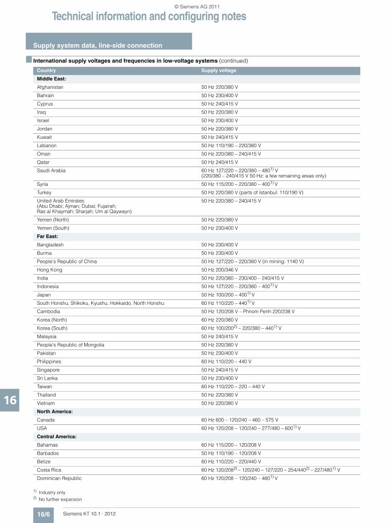
Technical information and configuring notes
Supply system data, line-side connection
16/6 Siemens KT 10.1 · 2012
16
■ International supply voltages and frequencies in low-voltage systems (continued)
1) Industry only 2) No further expansion
Country Supply voltage
Middle East:
Afghanistan 50 Hz 220/380 V
Bahrain 50 Hz 230/400 V
Cyprus 50 Hz 240/415 V
Iraq 50 Hz 220/380 V
Israel 50 Hz 230/400 V
Jordan 50 Hz 220/380 V
Kuwait 50 Hz 240/415 V
Lebanon 50 Hz 110/190 – 220/380 V
Oman 50 Hz 220/380 – 240/415 V
Qatar 50 Hz 240/415 V
Saudi Arabia 60 Hz 127/220 – 220/380 – 4801) V(220/380 – 240/415 V 50 Hz: a few remaining areas only)
Syria 50 Hz 115/200 – 220/380 – 4001) V
Turkey 50 Hz 220/380 V (parts of Istanbul: 110/190 V)
United Arab Emirates(Abu Dhabi; Ajman; Dubai; Fujairah;Ras al Khaymah; Sharjah; Um al Qaywayn)
50 Hz 220/380 – 240/415 V
Yemen (North) 50 Hz 220/380 V
Yemen (South) 50 Hz 230/400 V
Far East:
Bangladesh 50 Hz 230/400 V
Burma 50 Hz 230/400 V
People's Republic of China 50 Hz 127/220 – 220/380 V (in mining: 1140 V)
Hong Kong 50 Hz 200/346 V
India 50 Hz 220/380 – 230/400 – 240/415 V
Indonesia 50 Hz 127/220 – 220/380 – 4001) V
Japan 50 Hz 100/200 – 4001) V
South Honshu, Shikoku, Kyushu, Hokkaido, North Honshu 60 Hz 110/220 – 4401) V
Cambodia 50 Hz 120/208 V – Phnom Penh 220/238 V
Korea (North) 60 Hz 220/380 V
Korea (South) 60 Hz 100/2002) – 220/380 – 4401) V
Malaysia 50 Hz 240/415 V
People's Republic of Mongolia 50 Hz 220/380 V
Pakistan 50 Hz 230/400 V
Philippines 60 Hz 110/220 – 440 V
Singapore 50 Hz 240/415 V
Sri Lanka 50 Hz 230/400 V
Taiwan 60 Hz 110/220 – 220 – 440 V
Thailand 50 Hz 220/380 V
Vietnam 50 Hz 220/380 V
North America:
Canada 60 Hz 600 – 120/240 – 460 – 575 V
USA 60 Hz 120/208 – 120/240 – 277/480 – 6001) V
Central America:
Bahamas 60 Hz 115/200 – 120/208 V
Barbados 50 Hz 110/190 – 120/208 V
Belize 60 Hz 110/220 – 220/440 V
Costa Rica 60 Hz 120/2082) – 120/240 – 127/220 – 254/4402) – 227/4801) V
Dominican Republic 60 Hz 120/208 – 120/240 – 4801) V
KT10_EN_gesamt.book Seite 6 Mittwoch, 12. Oktober 2011 11:00 11
© Siemens AG 2011

Technical information and configuring notes
Supply system data, line-side connection
16/7Siemens KT 10.1 · 2012
16
■ International supply voltages and frequencies in low-voltage systems (continued)
1) Industry only2) No further expansion
Country Supply voltage
Central America (continued):
Guatemala 60 Hz 120/208 – 120/240 – 127/220 – 277/4801) – 4801) – 5501) V
Haiti 50 Hz 220/380 V (Jacmel), 60 Hz 110/220 V
Honduras 60 Hz 110/220 – 127/220 – 277/480 V
Jamaica 50 Hz 110/220 – 4401) V
Cuba 60 Hz 120/240 – 220/380 – 277/4801) – 4401) V
Mexico 60 Hz 127/220 – 4401) V
Nicaragua 60 Hz 110/220 – 120/240 – 127/220 – 220/440 – 254/401) V
Panama 60 Hz 120/2081) – 120/240 – 254/4401) – 277/4801) V
Puerto Rico 60 Hz 120/208 – 480 V
El Salvador 60 Hz 110/220 –120/208 –127/220 – 220/440 – 240/4801)
– 254/4401) V
Trinidad 60 Hz 110/220 – 120/240 – 230/400 V
South America:
Argentina 50 Hz 220/380 V
Bolivia 60 Hz 220/380 – 480 V, 50 Hz 110/220 – 220/380 V (exception)
Brazil 60 Hz 110/220 – 220/440 – 127/220 – 220/380 V
Chile 50 Hz 220/380 V
Ecuador 60 Hz 120/208 – 127/220 V
Guyana 50 Hz 110/220 V (Georgetown), 60 Hz 110/220 – 240/480 V
Columbia 60 Hz 110/220 – 150/260 – 440 V
Paraguay 60 Hz 220/380 – 220/440 V
Peru 60 Hz 220 – 220/380/440 V
Surinam 60 Hz 115/230 – 127/220 V
Uruguay 50 Hz 220 V
Venezuela 60 Hz 120/208 – 120/240 – 208/416 – 240/480 V
Africa:
Egypt 50 Hz 110/220 – 220/380 V
Ethiopia 50 Hz 220/380 V
Algeria 50 Hz 127/220 – 220/380 V
Angola 50 Hz 220/380 V
Benin 50 Hz 220/380 V
Ivory Coast 50 Hz 220/380 V
Gabon 50 Hz 220/380 V
Ghana 50 Hz 127/220 – 220/380 V
Guinea 50 Hz 220/380 V
Kenya 50 Hz 220/380 V
Cameroon 50 Hz 127/220 – 220/380 V
Congo 50 Hz 220/380 V
Liberia 60 Hz 120/208 – 120/240 V
Libya 50 Hz 127/2202) – 220/380 V
Madagascar 50 Hz 127/220 – 220/380 V
Malawi 50 Hz 220/380 V
Mali 50 Hz 220/380 V
Morocco 50 Hz 115/200 – 127/220 – 220/380 – 5001) V
Mauritius 50 Hz 240/415 V
Mozambique 50 Hz 220/380 V
Namibia 50 Hz 220/380 V
Niger 50 Hz 220/380 V
KT10_EN_gesamt.book Seite 7 Mittwoch, 12. Oktober 2011 11:00 11
© Siemens AG 2011

Technical information and configuring notes
Supply system data, line-side connection
16/8 Siemens KT 10.1 · 2012
16
■ International supply voltages and frequencies in low-voltage systems (continued)
■ Connection and fusing on the line side
All SITOP and LOGO!Power supplies are built-in devices. Compliance with the pertinent country-specific regulations is essential for installation and electrical connection of the devices. During installation, protective gear and isolating gear must be provided for activating the power supply.
Power supply units cause a current inrush immediately after connection of the input voltage due to charging of the load capacitor, however, it falls back to the rated input current level after a few milliseconds. Aside from the internal impedances of the power supply, the inrush current is dependent on the size of the input voltage applied as well as the source impedance of the supply network and the line impedance of the supply line. The maximum inrush current for the power supplies is specified in the applicable technical data. It is important for dimensioning up-circuit protective devices.
Single-phase SITOP and LOGO!Power supplies are equipped with internal device protection (fuses). For connection to the supply system, only one protective device (fuse or MCB) must be provided for line protection in accordance with the rated current of the installed cable. The circuit-breakers recommended in the data sheets and operating instructions were selected such that even during the maximum inrush current that can occur under worst-case conditions when switching on the supply voltage, the circuit-breaker will not trip. A two-pole connected miniature circuit-breaker is required for the connection of certain device types.
Three-phase SITOP power supplies do not have internal device protection. The up-circuit protective device (three-phase coupled miniature circuit-breaker or motor protection switch) protects the cables and devices. The protective devices specified in the data sheets and operating instructions are optimized to the characteristics of the relevant power supplies.
1) Industry only
Country Supply voltage
Africa (continued):
Nigeria 50 Hz 220/415 V
Rwanda 50 Hz 220/380 V
Zambia 50 Hz 220/380 V – 415 – 550 1) V
Senegal 50 Hz 127/220 – 220/380 V
Sierra Leone 50 Hz 220/380 V
Somalia 50 Hz 220-220/440 V
Sudan 50 Hz 240/415 V
South Africa 50 Hz 220/380 – 500 1) – 550/950 1) V
Swaziland 50 Hz 220/380 V
Tanzania 50 Hz 230/400 V
Togo 50 Hz 127/220 – 220/380 V
Tunisia 50 Hz 115/200 – 220/380 V
Uganda 50 Hz 240/415 V
Zaire 50 Hz 220/380 V
Zimbabwe 50 Hz 220/380 V
KT10_EN_gesamt.book Seite 8 Mittwoch, 12. Oktober 2011 11:00 11
© Siemens AG 2011
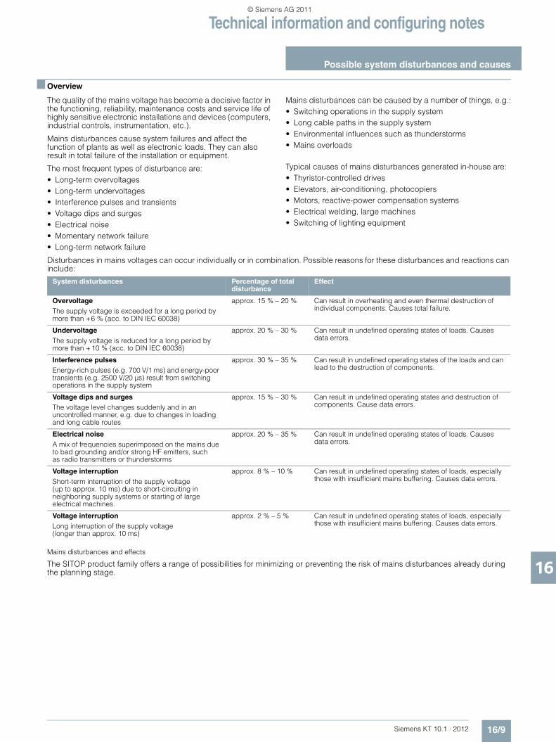
Technical information and configuring notes
Possible system disturbances and causes
16/9Siemens KT 10.1 · 2012
16
■ Overview
The quality of the mains voltage has become a decisive factor in the functioning, reliability, maintenance costs and service life of highly sensitive electronic installations and devices (computers, industrial controls, instrumentation, etc.).
Mains disturbances cause system failures and affect the function of plants as well as electronic loads. They can also result in total failure of the installation or equipment.
The most frequent types of disturbance are:• Long-term overvoltages• Long-term undervoltages• Interference pulses and transients• Voltage dips and surges• Electrical noise• Momentary network failure• Long-term network failure
Mains disturbances can be caused by a number of things, e.g.:• Switching operations in the supply system• Long cable paths in the supply system• Environmental influences such as thunderstorms• Mains overloads
Typical causes of mains disturbances generated in-house are:• Thyristor-controlled drives• Elevators, air-conditioning, photocopiers• Motors, reactive-power compensation systems• Electrical welding, large machines• Switching of lighting equipment
Disturbances in mains voltages can occur individually or in combination. Possible reasons for these disturbances and reactions can include:
Mains disturbances and effects
The SITOP product family offers a range of possibilities for minimizing or preventing the risk of mains disturbances already during the planning stage.
System disturbances Percentage of total disturbance
Effect
OvervoltageThe supply voltage is exceeded for a long period by more than +6 % (acc. to DIN IEC 60038)
approx. 15 % – 20 % Can result in overheating and even thermal destruction of individual components. Causes total failure.
UndervoltageThe supply voltage is reduced for a long period by more than + 10 % (acc. to DIN IEC 60038)
approx. 20 % – 30 % Can result in undefined operating states of loads. Causes data errors.
Interference pulsesEnergy-rich pulses (e.g. 700 V/1 ms) and energy-poor transients (e.g. 2500 V/20 µs) result from switching operations in the supply system
approx. 30 % – 35 % Can result in undefined operating states of the loads and can lead to the destruction of components.
Voltage dips and surgesThe voltage level changes suddenly and in an uncontrolled manner, e.g. due to changes in loading and long cable routes
approx. 15 % – 30 % Can result in undefined operating states and destruction of components. Cause data errors.
Electrical noiseA mix of frequencies superimposed on the mains due to bad grounding and/or strong HF emitters, suchas radio transmitters or thunderstorms
approx. 20 % – 35 % Can result in undefined operating states of loads. Causes data errors.
Voltage interruptionShort-term interruption of the supply voltage (up to approx. 10 ms) due to short-circuiting in neighboring supply systems or starting of large electrical machines.
approx. 8 % – 10 % Can result in undefined operating states of loads, especially those with insufficient mains buffering. Causes data errors.
Voltage interruptionLong interruption of the supply voltage (longer than approx. 10 ms)
approx. 2 % – 5 % Can result in undefined operating states of loads, especially those with insufficient mains buffering. Causes data errors.
KT10_EN_gesamt.book Seite 9 Mittwoch, 12. Oktober 2011 11:00 11
© Siemens AG 2011
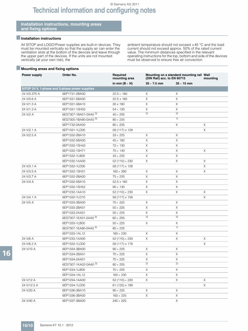
Technical information and configuring notes
Installation instructions, mounting areasand fixing options
16/10 Siemens KT 10.1 · 2012
16
■ Installation instructions
All SITOP and LOGO!Power supplies are built-in devices. They must be mounted vertically so that the supply air can enter the ventilation slots at the bottom of the devices and leave through the upper part of the devices. If the units are not mounted vertically (at your own risk), the
ambient temperature should not exceed +45 °C and the load current should not exceed approx. 50% of the rated current value. The minimum distances specified in the relevantoperating instructions for the top, bottom and side of the devices must be observed to ensure free air convection.
■ Mounting areas and fixing options
Power supply Order No. Requiredmounting area
Mounting on a standard mounting rail(DIN Rail) acc. to EN 60715
Wallmounting
in mm (B × H) 35 × 7.5 mm 35 × 15 mm
SITOP 24 V, 1-phase and 2-phase power supplies
24 V/0.375 A 6EP1731-2BA00 22.5 × 180 X X
24 V/0.6 A 6EP1331-5BA00 22.5 x 180 X X
24 V/1.3 A 6EP1331-5BA10 30 x 180 X X
24 V/1.3 A 6EP1331-1SH03 54 × 130 X X
24 V/2 A 6ES7307-1BA01-0AA0 3) 40 × 205 2) 2)
6ES7305-1BA80-0AA0 3) 80 × 225 1)
6EP1732-0AA00 80 × 235 X X
24 V/2.1 A 6EP1331-1LD00 58 (117) x 128 X
24 V/2.5 A 6EP1332-2BA10 33 × 225 X X
6EP1332-5BA00 45 × 180 X X
6EP1332-1SH43 72 × 130 X X
6EP1332-1SH71 70 × 140 X X X
6EP1332-1LB00 33 × 225 X X
6EP1232-1AA00 52 (110) × 230 X X X
24 V/3.1 A 6EP1332-1LD00 58 (117) x 128 X
24 V/3.5 A 6EP1332-1SH31 160 × 280 X X X
24 V/3.7 A 6EP1332-2BA00 75 × 225 X X
24 V/4 A 6EP1332-5BA10 52.5 x 180 X X
6EP1332-1SH52 90 × 130 X X
6EP1232-1AA10 52 (110) × 230 X X X
24 V/4.1 A 6EP1332-1LD10 58 (117) x 158 X
24 V/5 A 6EP1333-3BA00 70 × 225 X X
6EP1333-2BA01 50 × 225 X X
6EP1333-2AA01 50 × 225 X X
6ES7307-1EA01-0AA0 3) 60 × 205 2) 2)
6EP1333-1LB00 50 × 225 X X
6ES7307-1EA80-0AA0 3) 80 × 225 1)
6EP1333-1AL12 160 × 230 X X
24 V/6 A 6EP1233-1AA00 52 (110) × 230 X X X
24 V/6.2 A 6EP1333-1LD00 58 (117) x 178 X
24 V/10 A 6EP1334-3BA00 90 × 225 X X
6EP1334-2BA01 70 × 225 X X
6EP1334-2AA01 70 × 225 X X
6ES7307-1KA02-0AA0 3) 80 × 205 2) 2)
6EP1334-1LB00 70 × 225 X X
6EP1334-1AL12 160 × 230 X X
24 V/12 A 6EP1234-1AA00 52 (110) × 230 X X X
24 V/12.5 A 6EP1334-1LD00 61 (125) x 199 X
24 V/20 A 6EP1336-3BA10 90 × 225 X X
6EP1336-3BA00 160 × 225 X X
24 V/40 A 6EP1337-3BA00 240 × 225 X
KT10_EN_gesamt.book Seite 10 Mittwoch, 12. Oktober 2011 11:00 11
© Siemens AG 2011
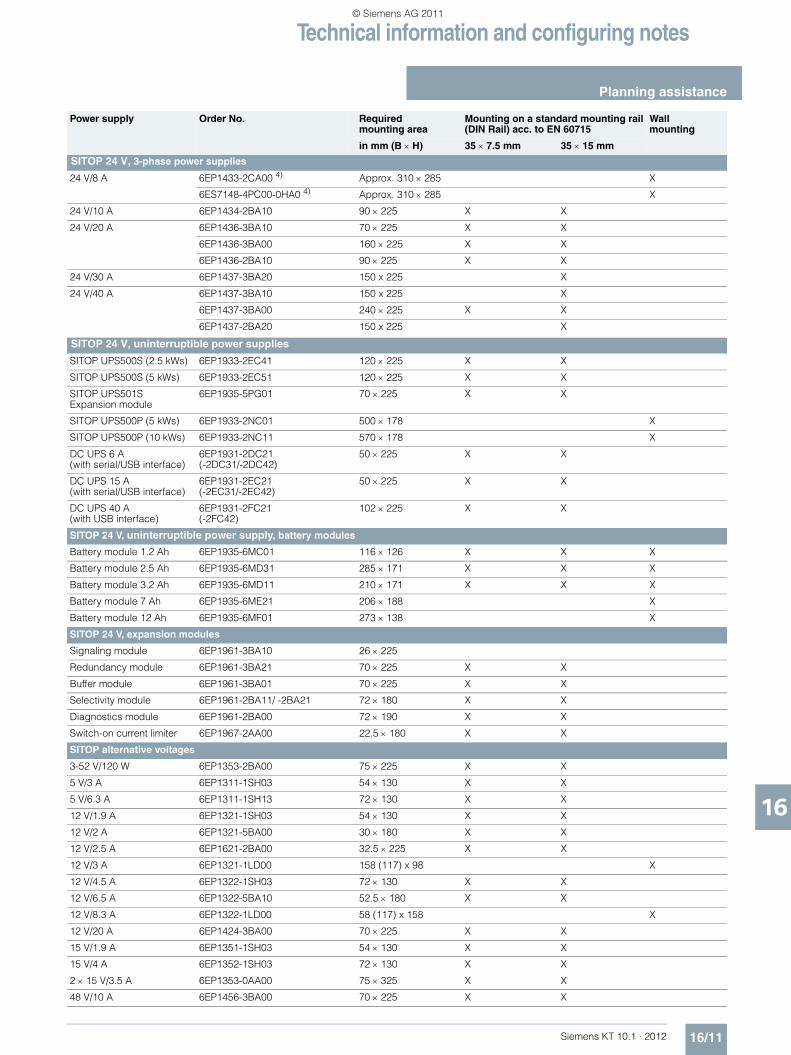
Technical information and configuring notes
Planning assistance
16/11Siemens KT 10.1 · 2012
16
SITOP 24 V, 3-phase power supplies
24 V/8 A 6EP1433-2CA00 4) Approx. 310 × 285 X
6ES7148-4PC00-0HA0 4) Approx. 310 × 285 X
24 V/10 A 6EP1434-2BA10 90 × 225 X X
24 V/20 A 6EP1436-3BA10 70 × 225 X X
6EP1436-3BA00 160 × 225 X X
6EP1436-2BA10 90 × 225 X X
24 V/30 A 6EP1437-3BA20 150 x 225 X
24 V/40 A 6EP1437-3BA10 150 x 225 X
6EP1437-3BA00 240 × 225 X X
6EP1437-2BA20 150 x 225 X
SITOP 24 V, uninterruptible power supplies
SITOP UPS500S (2.5 kWs) 6EP1933-2EC41 120 × 225 X X
SITOP UPS500S (5 kWs) 6EP1933-2EC51 120 × 225 X X
SITOP UPS501S Expansion module
6EP1935-5PG01 70 × 225 X X
SITOP UPS500P (5 kWs) 6EP1933-2NC01 500 × 178 X
SITOP UPS500P (10 kWs) 6EP1933-2NC11 570 × 178 X
DC UPS 6 A(with serial/USB interface)
6EP1931-2DC21(-2DC31/-2DC42)
50 × 225 X X
DC UPS 15 A(with serial/USB interface)
6EP1931-2EC21(-2EC31/-2EC42)
50 × 225 X X
DC UPS 40 A(with USB interface)
6EP1931-2FC21(-2FC42)
102 × 225 X X
SITOP 24 V, uninterruptible power supply, battery modules
Battery module 1.2 Ah 6EP1935-6MC01 116 × 126 X X X
Battery module 2.5 Ah 6EP1935-6MD31 285 × 171 X X X
Battery module 3.2 Ah 6EP1935-6MD11 210 × 171 X X X
Battery module 7 Ah 6EP1935-6ME21 206 × 188 X
Battery module 12 Ah 6EP1935-6MF01 273 × 138 X
SITOP 24 V, expansion modules
Signaling module 6EP1961-3BA10 26 × 225
Redundancy module 6EP1961-3BA21 70 × 225 X X
Buffer module 6EP1961-3BA01 70 × 225 X X
Selectivity module 6EP1961-2BA11/ -2BA21 72 × 180 X X
Diagnostics module 6EP1961-2BA00 72 × 190 X X
Switch-on current limiter 6EP1967-2AA00 22.5 × 180 X X
SITOP alternative voltages
3-52 V/120 W 6EP1353-2BA00 75 × 225 X X
5 V/3 A 6EP1311-1SH03 54 × 130 X X
5 V/6.3 A 6EP1311-1SH13 72 × 130 X X
12 V/1.9 A 6EP1321-1SH03 54 × 130 X X
12 V/2 A 6EP1321-5BA00 30 × 180 X X
12 V/2.5 A 6EP1621-2BA00 32.5 × 225 X X
12 V/3 A 6EP1321-1LD00 158 (117) x 98 X
12 V/4.5 A 6EP1322-1SH03 72 × 130 X X
12 V/6.5 A 6EP1322-5BA10 52.5 × 180 X X
12 V/8.3 A 6EP1322-1LD00 58 (117) x 158 X
12 V/20 A 6EP1424-3BA00 70 × 225 X X
15 V/1.9 A 6EP1351-1SH03 54 × 130 X X
15 V/4 A 6EP1352-1SH03 72 × 130 X X
2 × 15 V/3.5 A 6EP1353-0AA00 75 × 325 X X
48 V/10 A 6EP1456-3BA00 70 × 225 X X
Power supply Order No. Requiredmounting area
Mounting on a standard mounting rail(DIN Rail) acc. to EN 60715
Wallmounting
in mm (B × H) 35 × 7.5 mm 35 × 15 mm
KT10_EN_gesamt.book Seite 11 Mittwoch, 12. Oktober 2011 11:00 11
© Siemens AG 2011
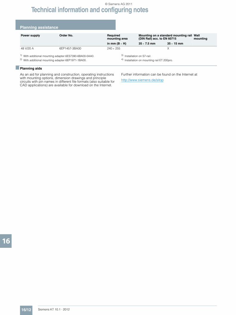
Technical information and configuring notes
Planning assistance
16/12 Siemens KT 10.1 · 2012
16
1) With additional mounting adapter 6ES7390-6BA00-0AA0.2) With additional mounting adapter 6EP1971-1BA00.
3) Installation on S7-rail.4) Installation on mounting rail ET 200pro.
■ Planning aids
As an aid for planning and construction, operating instructions with mounting options, dimension drawings and principle circuits with pin names in different file formats (also suitable for CAD applications) are available for download on the Internet.
Further information can be found on the Internet at
http://www.siemens.de/sitop
48 V/20 A 6EP1457-3BA00 240 × 255 X
Power supply Order No. Requiredmounting area
Mounting on a standard mounting rail(DIN Rail) acc. to EN 60715
Wallmounting
in mm (B × H) 35 × 7.5 mm 35 × 15 mm
KT10_EN_gesamt.book Seite 12 Mittwoch, 12. Oktober 2011 11:00 11
© Siemens AG 2011

Technical information and configuring notes
Parallel connection for redundant operationand performance enhancement
16/13Siemens KT 10.1 · 2012
16
■ Parallel connection for redundant operation
Two SITOP power supplies of the same type can be connected in parallel through diodes for a redundant configuration. 100% redundancy only exists for two power supplies when the total load current is no higher than that which one power supply can supply alone and when the supply for the primary side is also implemented redundantly (i.e. a short-circuit on the primary side will not trigger a shared fuse which would disconnect both power supplies from the mains).
Parallel connection with decoupling diodes for redundant operation is permitted for all SITOP power supplies. The diodes V1 and V2 are used for decoupling. They must have a blocking voltage of at least 40 V and it must be possible to load them with a current equal to or greater than the maximum output current of the respective SITOP power supply. For diode dimensioning, see the following note "General information on selection of diodes".
The ready-to-use expansion "SITOP modular redundancy module" is available as a simple alternative to diode dimensioning (Order No.: 6EP1961-3BA21, see Section 11) for redundant connection of two power supplies.
General information on selection of diodes:
The diodes must be dimensioned for the maximum dynamic overcurrent. This can be the dynamic overcurrent during power-up in the short-circuit case, or the dynamic overcurrent during a short-circuit in operation (the largest of the two values should be taken from the relevant technical specifications).
To dissipate the significant power loss of the decoupling diodes (sustained short-circuit current × diode conductive-state voltage), the diodes must be equipped with suitably dimensioned heat sinks.
An additional safety margin is recommended, because the output capacitor integral to the power supply generates an additional peak current in the short-circuit case. This additional current flows only for a few milliseconds so it is within the period in which diodes are permitted to be loaded with a multiple of the rated current (< 8.3 ms, known as the permissible surge current for diodes) .
Parallel connection of two SITOP power supplies for redundant operation
Example
Two 1-phase SITOP modular power supplies with10 A rated output current, (Order No.: 6EP1 334-3BA00)are connected in parallel. The dynamic overcurrent in the event of a short-circuit during operation is approximately 30 A for 25 ms.
The diodes should therefore have a loading capability of 40 A to be safe, the common heat sink for both diodes must be dimensioned for the maximum possible current of approximately 24 A (sustained short-circuit current rms value) × diode conductive-state voltage.
SITOP
L+
M
SITOP
L+
M
V1
V2
Load
G_KT01_EN_00017
KT10_EN_gesamt.book Seite 13 Mittwoch, 12. Oktober 2011 11:00 11
© Siemens AG 2011

Technical information and configuring notes
Parallel connection for redundant operationand performance enhancement
16/14 Siemens KT 10.1 · 2012
16
■ Parallel connection for performance enhancement
To enhance performance, identical types of most SITOP power supplies can be connected in parallel galvanically (the same principle as parallel connection for redundant operation, but without decoupling diodes):
Advantage
The costs for mounting the diodes onto heat sinks and the not insignificant power losses for the decoupling diodes (current × diode conducting-state voltage) are avoided.
The types permitted for direct galvanic parallel connection are listed in the relevant technical specifications under "Output, parallel connection for performance enhancement".
Prerequisite:• The output cables connected to terminals "+" and "–" of every
power supply should be installed with an identical length and cross-section (or the same impedance) to the common external linking point.
• The power supplies connected in parallel must be switched simultaneously using a common switch in the mains supply line (e.g. using the main switch available in control cabinets).
• The output voltages of the power supplies must be measured under no-load operation before they are connected in parallel and are permitted to differ by up to 50 mV. This usually corresponds to the factory default setting. If the output voltage is changed in case of variable power supplies, the "–" terminals should first be connected and then the voltage difference between the "+" output terminals measured under no-load conditions before these are connected. The voltage difference must not exceed 50 mV.
Note:
With a direct galvanic connection in parallel of more than two SITOP power supplies, further circuit measures may be necessary for short-circuit and overload protection!
■ Parallel connection for redundant operation andperformance enhancement
Almost 100% redundancy
Using the types permitted for direct galvanic parallel connection (see the relevant technical specifications under "Output, parallel connection for performance enhancement"), performance can be increased without the need for decoupling diodes, and simultaneously, redundancy of almost 100% can be implemented by direct galvanic parallel connection of an additional power supply of the same type to the power supplies required. This means that at least one power supply is required than is necessary for the sum of all load currents.
A decoupling diode is normally required for redundancy to ensure that a power supply that has failed as a result of short-circuiting of the outputs (especially as a result of short-circuiting the output electrolytic capacitor) does not also short-circuit the power supplies that remain intact. A redundancy of almost 100% can be implemented with this type of circuit.
Example
A load current of up to 40 A is required and the power supplies must operate on both 400 V and 500 V three-phase supplies (without switch-over).
The three-phase type SITOP modular 20 A is suitable for this(Order No.: 6EP1 436-3BA10). For load currents up to 40 A,direct galvanic parallel connection of two SITOP modular power 20 supplies is necessary. By connecting another SITOP modular 20 in parallel, performance enhancement and redundancy are implemented simultaneously (if one of the three power supplies fails to supply an output voltage, the remaining two 20 A power supplies are capable of supplying a total load current of 40 A).
Note:
With a direct galvanic connection in parallel of more than two SITOP power supplies, further circuit measures may be necessary for short-circuit and overload protection!
KT10_EN_gesamt.book Seite 14 Mittwoch, 12. Oktober 2011 11:00 11
© Siemens AG 2011

Technical information and configuring notes
Series connection to increase the voltage
16/15Siemens KT 10.1 · 2012
16
■ Series connection to increase the voltage
To generate a load voltage of e. g. 48 V DC, two 24 V SITOP power supplies of the same type can be connected in series. The SITOP outputs "+" and "–" are isolated up to at least 60 V DC against PE (creepage and clearances as well as radio interference suppression capacitors on "+" and "–" against PE), so that with this type of series connection (see Figure), the following points can be grounded:• "–" of the lower power supply (results in +48 V DC against PE) • Midway "+"/ "–" between both power supplies
(results in ±24 VDC against PE)• "+" of the lower power supply (results in -48 V DC against PE)
Note:
If two devices are connected in parallel, it cannot be guaranteed that the voltage will remain below the maximum permissible SELV voltage of 60 V DC in the event of a fault.
The purpose of diodes V1 and V2 is to protect the electrolytic output capacitor integrated in the power supply against reverse voltages > 1 V. As a result of the not absolutely simultaneous power-up (even when a common mains switch is used for switching on, differences of a few tens of milliseconds can occur between the various startup-up delays), the power supply which starts up more quickly supplies current from output "–" of the slower power supply whose output electrolytic capacitor is then theoretically impermissibly discharged.
The internal LC filter causes the internal rectifier diode on the secondary side of the slower-starting power supply to accept this current a few milliseconds later; this means that the external diode connected with its anode to "–" and cathode to "+" is essential on each power supply. These diodes are, however, only loaded dynamically, so that the 8.3 ms surge current loading capability (specified in the data sheets for suitable diodes) can be used as a basis for dimensioning and it is not usually necessary to cool the diodes using heat sinks.
1) We do not accept any liability for this diode recommendation.
Series connection of two SITOP power units to double the voltage
Example:
Two single-phase SITOP modular power supplies with 10 A rated output current (Order No.: 6EP1 334-1AL12) should be connected in series for increasing the voltage. They supply approximately 35 A dynamically for 700 ms on power-up in the short-circuit case or also, for example, with loads with a high-capacity input capacitor that momentarily act as a short-circuit at the start.
Suitable diodes for V1 and V2 are, for example, of Type SB 3401) (Schottky diode in axially wired enclosure DO-201AD with approximately 5.3 mm diameter and approximately 9.5 mm length of body).
40 V are permissible as the blocking voltage, and the stationary direct current load capacity IF AV is 3 A. The dynamic surge current loading capacity IF SM important in this case is sufficient for the selected SITOP power supply at more than 100 A for 8.3 ms. For SITOP power supplies with a lower rated output current, this diode can also be used, but it is over-dimensioned.• Manufacturer: General Instrument • Distributor: e.g. RS Components, Spoerle
SITOP power
+
-
SITOP power
+
-G_KT01_EN_00059
Load
KT10_EN_gesamt.book Seite 15 Mittwoch, 12. Oktober 2011 11:00 11
© Siemens AG 2011

Technical information and configuring notes
Battery charging, fusing of the 24 V DC output circuit, selectivity
16/16 Siemens KT 10.1 · 2012
16
■ Battery charging with SITOP power supplies
The power supplies SITOP PSU300M12 V/20 A (Order No. 6EP1424-3BA00) and 24 V/30 A (Order No. 6EP1437-3BA20) are suitable for charging lead batteries.
In the case of a V/I characteristic set for parallel operation, the battery will be charged with a constant current until approximately 95 % of the set SITOP output voltage has been achieved. The charging current is then continuously reduced from 1.2 × rated current at 95 % of the set voltage to approximately 0 A or the self-discharge current of the battery at 100 % of the set output voltage, that is, resistance characteristic in this range.
As reverse voltage protection and polarity reversal protection, we recommend that a diode suitable for at least 1.2 × rated current of the power supply with a blocking voltage of at least 40 V is connected in series with the "+" output (anode connected to "+" output of the SITOP modular and cathode connected to positive pole of the battery)..
The output voltage of the power supply must be set at no-load to the end-of-charge voltage plus the voltage drop at the diode. For an end-of-charge voltage of e. g. 27.0 V DC (usual at 20 °C to 30 °C battery temperature; in each case, compliance with the specifications of the battery manufacturer must be observed!) and 0.8 V voltage drop at the diode, SITOP modular must be set to 27.8 V during no-load operation.
General note for using SITOP power supplies as a battery-charging unit
When SITOP modular is used as a battery charging unit, the regulations of VDE 0510 or the relevant national regulations must be observed, and adequate ventilation of the battery location must be provided. The SITOP modular power supplies are designed as rack-mounting units, and protection against electric shock should therefore be provided by installation in an appropriate housing.
The value recommended by the battery manufacturer must be set as the end-of-charge voltage (depending on the battery temperature). An ideal temperature for the lead-acid battery is between +20 to 30 °C and the recommended end-of-charge voltage in this case is usually about 27 V.
■ Fusing of 24 V power supply circuits andselectivity
With non-stabilized rectifiers (power transformer equipped with rectifier) the output usually had to be protected with a suitable fuse so that its rectifier diodes would not fail in the event of an overload or a short-circuit (this would destroy the DC loads due to the resulting alternating voltage and lead to serious damage in most cases).
On the other hand, the stabilized SITOP power supplies are provided with integral electronic short-circuit protection that automatically protects both the power supply and the supplied 24 V DC circuits against an excess current in the event of an overload/short-circuit. A distinction must be made between the following three cases with respect to fusing on the secondary side:
Example 1: No fusing
Fusing the secondary side (24 V DC) for protecting the load circuits and lines is not required if the respective cross-sections are selected for the maximum possible output current RMS value. Depending on the event (short-circuit or overload) this may either be the short-circuit RMS value or the current limitation value.
■ Fusing of 24 V power supply circuits andselectivity (continued)
Example SITOP modular 10 A (Order No.: 6EP1334-3BA00) • 10 A rated current• Current limitation typ. 12 A • Short-circuit current rms value approximately 12 A
The technical specifications usually specify typical values, maximum values are approximately 2 A above the typical value. In the example here, a maximum possible output current rms value of approximately 14 must therefore be used for line dimensioning.
Example 2: Reduced conductor cross-sections
If smaller conductor cross-sections are used than specified in the relevant standards (e.g. EN 60204-1), the affected 24 V load infeed cables must be protected with a suitable circuit breaker.
It is then unimportant whether the power supply enters current limiting mode (overload) or delivers the maximum short-circuit current (low-resistance short-circuit).The load supply is in any case protected against an overload by the line protection matched to the conductor cross-section.
Example 3: Selectivity
In cases where a load which has failed (e.g. because of a short-circuit) has to be rapidly detected or where it is essential to selectively switch it off before the power supply enters current limiting mode (with current limiting mode, the voltage would also fall for all remaining 24 V DC loads), there are two possibilities for the secondary side connection:• A selectivity module SITOP PSE200U or a diagnostics
module SITOP select for the distribution of the 24 V DC supply over up to 4 load feeders. Each output is adjustable between 0.5 A and 3 A (Order No.: 6EP1961-2BA11) or 3 A and 10 A ( (Order No.: 6EP1961-2BA21) or 2 A and 10 A ( Order No.: 6EP1961-2BA00).
• Series connection of appropriate 24 V DC fuses or miniature circuit breakers
The basis for selection of the 24 V DC fuse or circuit-breaker is the short-circuit current above the rated current which the SITOP power supplies deliver in the event of a short-circuit during operation (values are specified in the respective technical specifications under "Output, dynamic V/I on short-circuit during operation").
It is not easy to calculate the amount of the short-circuit current flowing into the usually not ideal "short-circuit" and the amount flowing into the remaining loads. This depends on the type of overload (high-resistance or low-resistance short-circuit) and the type of load connected (resistive, inductive and capacitive/electronic loads).
However, it can be assumed with a first approximation in the average case encountered in practice that the difference of dynamic overcurrent minus 50 % SITOP rated output current is available for the immediate tripping of a circuit-breaker within a typical time of 12 ms (with 14 times the rated DC with a circuit-breaker characteristic C acc. to IEC 898, or with 7 times the rated DC with a circuit-breaker characteristic B or with 5 times the rated DC with a circuit-breaker characteristic A). Please refer to the following tables for circuit-breakers appropriate for selected fusing according to this assumption.
KT10_EN_gesamt.book Seite 16 Mittwoch, 12. Oktober 2011 11:00 11
© Siemens AG 2011
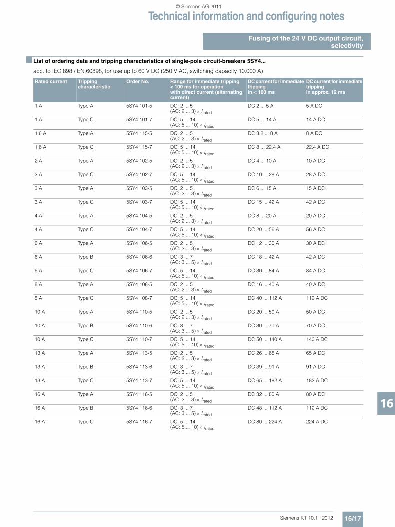
Technical information and configuring notes
Fusing of the 24 V DC output circuit,selectivity
16/17Siemens KT 10.1 · 2012
16
■ List of ordering data and tripping characteristics of single-pole circuit-breakers 5SY4...
acc. to IEC 898 / EN 60898, for use up to 60 V DC (250 V AC, switching capacity 10.000 A)
Rated current Tripping characteristic
Order No. Range for immediate tripping< 100 ms for operation with direct current (alternating current)
DC current for immediate tripping in < 100 ms
DC current for immediate tripping in approx. 12 ms
1 A Type A 5SY4 101-5 DC: 2 ... 5 (AC: 2 ... 3) × Irated
DC 2 ... 5 A 5 A DC
1 A Type C 5SY4 101-7 DC: 5 ... 14 (AC: 5 ... 10) × Irated
DC 5 ... 14 A 14 A DC
1.6 A Type A 5SY4 115-5 DC: 2 ... 5 (AC: 2 ... 3) × Irated
DC 3.2 ... 8 A 8 A DC
1.6 A Type C 5SY4 115-7 DC: 5 ... 14 (AC: 5 ... 10) × Irated
DC 8 ... 22.4 A 22.4 A DC
2 A Type A 5SY4 102-5 DC: 2 ... 5 (AC: 2 ... 3) × Irated
DC 4 ... 10 A 10 A DC
2 A Type C 5SY4 102-7 DC: 5 ... 14 (AC: 5 ... 10) × Irated
DC 10 ... 28 A 28 A DC
3 A Type A 5SY4 103-5 DC: 2 ... 5(AC: 2 ... 3) × Irated
DC 6 ... 15 A 15 A DC
3 A Type C 5SY4 103-7 DC: 5 ... 14 (AC: 5 ... 10) × Irated
DC 15 ... 42 A 42 A DC
4 A Type A 5SY4 104-5 DC: 2 ... 5 (AC: 2 ... 3) × Irated
DC 8 ... 20 A 20 A DC
4 A Type C 5SY4 104-7 DC: 5 ... 14 (AC: 5 ... 10) × Irated
DC 20 ... 56 A 56 A DC
6 A Type A 5SY4 106-5 DC: 2 ... 5 (AC: 2 ... 3) × Irated
DC 12 ... 30 A 30 A DC
6 A Type B 5SY4 106-6 DC: 3 ... 7 (AC: 3 ... 5) × Irated
DC 18 ... 42 A 42 A DC
6 A Type C 5SY4 106-7 DC: 5 ... 14 (AC: 5 ... 10) × Irated
DC 30 ... 84 A 84 A DC
8 A Type A 5SY4 108-5 DC: 2 ... 5 (AC: 2 ... 3) × Irated
DC 16 ... 40 A 40 A DC
8 A Type C 5SY4 108-7 DC: 5 ... 14 (AC: 5 ... 10) × Irated
DC 40 ... 112 A 112 A DC
10 A Type A 5SY4 110-5 DC: 2 ... 5 (AC: 2 ... 3) × Irated
DC 20 ... 50 A 50 A DC
10 A Type B 5SY4 110-6 DC: 3 ... 7 (AC: 3 ... 5) × Irated
DC 30 ... 70 A 70 A DC
10 A Type C 5SY4 110-7 DC: 5 ... 14 (AC: 5 ... 10) × Irated
DC 50 ... 140 A 140 A DC
13 A Type A 5SY4 113-5 DC: 2 ... 5 (AC: 2 ... 3) × Irated
DC 26 ... 65 A 65 A DC
13 A Type B 5SY4 113-6 DC: 3 ... 7 (AC: 3 ... 5) × Irated
DC 39 ... 91 A 91 A DC
13 A Type C 5SY4 113-7 DC: 5 ... 14 (AC: 5 ... 10) × Irated
DC 65 ... 182 A 182 A DC
16 A Type A 5SY4 116-5 DC: 2 ... 5 (AC: 2 ... 3) × Irated
DC 32 ... 80 A 80 A DC
16 A Type B 5SY4 116-6 DC: 3 ... 7 (AC: 3 ... 5) × Irated
DC 48 ... 112 A 112 A DC
16 A Type C 5SY4 116-7 DC: 5 ... 14 (AC: 5 ... 10) × Irated
DC 80 ... 224 A 224 A DC
KT10_EN_gesamt.book Seite 17 Mittwoch, 12. Oktober 2011 11:00 11
© Siemens AG 2011

Technical information and configuring notes
Fusing of the 24 V DC output circuit,selectivity
16/18 Siemens KT 10.1 · 2012
16
■ Miniature circuit breakers 1) according to EN 60898 (DIN VDE 0641 T11), in 24 V DC circuitswhich are powered by SITOP modular or SITOP smart power supplies
Iout rated: Rated output current.Iout dyn: Dynamic overcurrent at short-circuit in operation.✔: Immediate tripping, since dynamic overcurrent resulting from a
short circuit > limit current of electromagnetic tripping. ❍: Immediate tripping very likely, since at least 50 % of dynamic
overcurrent resulting from a short circuit is within tripping characteristic.
X: No immediate tripping.
1) This selection of miniature circuit breakers is based on the maximum possible short-circuit current of the power supply and on the tripping characteristic at +20 °C. Other criteria, which might also be relevant in practice, like for example self-heating, ambient temperature, line impedance, and currents flowing in parallel paths, were not considered.
Order No. Iout rated Iout dyn Characteristic A
1 A 1.6 A 2 A 3 A 4 A 6 A 8 A 10 A 13 A 16 A
6EP1332-2BA10
2.5 A 7 A/200 ms ✓ ❍ ❍ X X X X X X X
6EP1333-3BA00
5 A 15 A/25 ms ✓ ✓ ✓ ❍ ❍ X X X X X
6EP1333-2BA01
5 A 17 A/200 ms ✓ ✓ ✓ ✓ ❍ X X X X X
6EP1333-2AA01
5 A 17 A/200 ms ✓ ✓ ✓ ✓ ❍ X X X X X
6EP1334-3BA00
10 A 30 A/25 ms ✓ ✓ ✓ ✓ ✓ ✓ ❍ X X X
6EP1334-2BA01
10 A 33 A/200 ms ✓ ✓ ✓ ✓ ✓ ✓ ❍ X X X
6EP1334-2AA01
10 A 33 A/200 ms ✓ ✓ ✓ ✓ ✓ ✓ ❍ X X X
6EP1434-2BA10
10 A 16 A/100 ms ✓ ✓ ✓ ✓ ❍ X X X X X
6EP1336-3BA00
20 A 60 A/25 ms ✓ ✓ ✓ ✓ ✓ ✓ ✓ ✓ ❍ ❍
6EP1336-3BA10
20 A 60 A/25 ms ✓ ✓ ✓ ✓ ✓ ✓ ✓ ✓ ❍ ❍
6EP1436-3BA00
20 A 60 A/25 ms ✓ ✓ ✓ ✓ ✓ ✓ ✓ ✓ ❍ ❍
6EP1436-3BA10
20 A 60 A/25 ms ✓ ✓ ✓ ✓ ✓ ✓ ✓ ✓ ❍ ❍
6EP1436-2BA10
20 A 35 A/100 ms ✓ ✓ ✓ ✓ ✓ ✓ ❍ ❍ X X
6EP1337-3BA00
40 A 120 A/25 ms ✓ ✓ ✓ ✓ ✓ ✓ ✓ ✓ ✓ ✓
6EP1437-3BA00
40 A 120 A/25 ms ✓ ✓ ✓ ✓ ✓ ✓ ✓ ✓ ✓ ✓
6EP1437-3BA10
40 A 120 A/25 ms ✓ ✓ ✓ ✓ ✓ ✓ ✓ ✓ ✓ ✓
6EP1437-2BA20
40 A 65 A/120 ms ✓ ✓ ✓ ✓ ✓ ✓ ✓ ✓ ✓ ❍
KT10_EN_gesamt.book Seite 18 Mittwoch, 12. Oktober 2011 11:00 11
© Siemens AG 2011
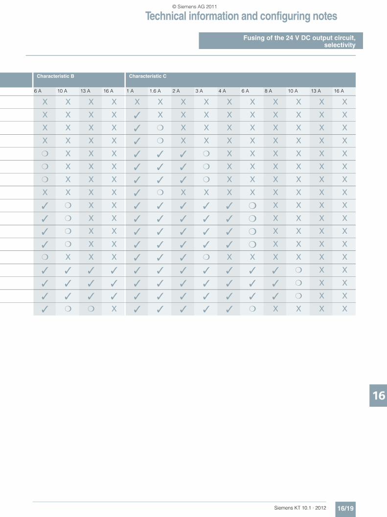
Technical information and configuring notes
Fusing of the 24 V DC output circuit,selectivity
16/19Siemens KT 10.1 · 2012
16
Characteristic B Characteristic C
6 A 10 A 13 A 16 A 1 A 1.6 A 2 A 3 A 4 A 6 A 8 A 10 A 13 A 16 A
X X X X X X X X X X X X X X
X X X X ✓ X X X X X X X X X
X X X X ✓ ❍ X X X X X X X X
X X X X ✓ ❍ X X X X X X X X
❍ X X X ✓ ✓ ✓ ❍ X X X X X X
❍ X X X ✓ ✓ ✓ ❍ X X X X X X
❍ X X X ✓ ✓ ✓ ❍ X X X X X X
X X X X ✓ ❍ X X X X X X X X
✓ ❍ X X ✓ ✓ ✓ ✓ ✓ ❍ X X X X
✓ ❍ X X ✓ ✓ ✓ ✓ ✓ ❍ X X X X
✓ ❍ X X ✓ ✓ ✓ ✓ ✓ ❍ X X X X
✓ ❍ X X ✓ ✓ ✓ ✓ ✓ ❍ X X X X
❍ X X X ✓ ✓ ✓ ❍ X X X X X X
✓ ✓ ✓ ✓ ✓ ✓ ✓ ✓ ✓ ✓ ✓ ❍ X X
✓ ✓ ✓ ✓ ✓ ✓ ✓ ✓ ✓ ✓ ✓ ❍ X X
✓ ✓ ✓ ✓ ✓ ✓ ✓ ✓ ✓ ✓ ✓ ❍ X X
✓ ❍ ❍ X ✓ ✓ ✓ ✓ ✓ ❍ X X X X
KT10_EN_gesamt.book Seite 19 Mittwoch, 12. Oktober 2011 11:00 11
© Siemens AG 2011

Technical information and configuring notes
Standards and approvals
16/20 Siemens KT 10.1 · 2012
16
■ Overview of important standards and approvals
■ Further information
Additional information is available in the Internet under:• 2D dimensional drawings, 3D CAD data, circuit diagram
macros: www.siemens.com/sitop-cax
• Operating instructions:www.siemens.de/sitop-manuals
• Find the right product with the SITOP Selection Tool: www.siemens.com/sitop-selection-tool
EN European standards
EN 50178 Electronic equipment for use in power installations
EN 55022 Information technology equipment – Radio disturbance characteristics – Limits and methods of measurement
EN 60529 Degrees of protection provided by enclosures (IP-Code)
EN 60721 Classification of environmental conditions
EN 60950-1 Information technology equipment – Safety
EN 61000-3-2 Electromagnetic compatibility (EMC) – Part 3-2: Limits for harmonic current emissions (equipment input current ≤ 16 A per phase)
EN 61000-6-2 Electromagnetic compatibility (EMC) – Part 6-2: Generic standards – Immunity for industrial environments
EN 61000-6-3 Electromagnetic compatibility (EMC) – Part 6-3: Generic standards – Emission standard for residential, commercial and light industrial environments
UL Underwriters Laboratories
UL 508 Industrial control equipment
UL 1604 Electrical equipment for use in class I and class II, division 2. and class III hazardous (classified) locations
UL 1778 Uninterruptible power supply equipment
UL 2367 Standard for solid state overcurrent protectors
UL 60079 Electrical apparatus for explosive gas atmospheres
UL 60950 -1 Information technology equipment – Safety
CSA Canadian Standards Association
CSA C22.2 No. 14 Industrial control equipment
CSA C22.2 No. 142 Process control equipment
CSA C22.2 No. 107.1 General use power supplies
CSA C22.2 No. 60079 Electrical apparatus for explosive gas atmospheres
CSA C22.2 No. 60950-1 Information technology equipment – Safety
ATEX Equipment and protective systems intended for use in Potentially Explosive Atmospheres
FM Factory Mutual Research
ABS American Bureau of Shipping
GL Germanischer Lloyd
KT10_EN_gesamt.book Seite 20 Mittwoch, 12. Oktober 2011 11:00 11
© Siemens AG 2011

Siemens KT 10.1 · 2012
1717/2 Partners at
Industry Automation and Drive Technologies
17/2 Contact partners worldwide17/3 Siemens Solution Partners
17/4 Online Services17/4 Information and ordering
in the Internet and on DVD
17/5 Service & Support17/5 Services covering the entire life cycle17/7 Knowledge Base on DVD17/7 Automation Value Card
17/8 Alphabetical index
17/9 Order No. index
17/12 Terms and conditions of sale and delivery
17/12 Export regulations
Appendix
KT10_EN_gesamt.book Seite 1 Mittwoch, 12. Oktober 2011 11:00 11
© Siemens AG 2011

AppendixPartner at Industry Automation and Drive Technologies
17/2 Siemens KT 10.1 · 2012
17
At Siemens Industry Automation and Drive Technologies, more than 85 000 people are resolutely pursuing the same goal: long-term improvement of your competitive ability. We are committed to this goal. Thanks to our commitment, we continue to set new standards in automation and drive technology. In all industries – worldwide.
At your service locally, around the globe for consulting, sales, training, service, support, spare parts ... on the entire Industry Automation and Drive Technologies range.
Your personal contact can be found in our Contacts Database at:www.siemens.com/automation/partner
You start by selecting a• Product group, • Country, • City, • Service.
KT10_EN_gesamt.book Seite 2 Mittwoch, 12. Oktober 2011 11:00 11
© Siemens AG 2011

AppendixPartner at Industry Automation and Drive Technologies
Siemens Solution Partner Automation
17/3Siemens KT 10.1 · 2012
17
■ Overview
Siemens Solution Partner Automation
Solution Partner: Highest quality - guaranteed
The products and systems from Siemens Industry Automation and Drive Technologies offer the ideal platform for all automation applications.
Under the name of Siemens Solution Partner Automation, selected system integrators around the world act as uniformly qualified solution providers for the Siemens range of products and services in the fields of automation and drives. Day after day, they utilize their qualified product and system know-how as well as their excellent industry expertise to your advantage – for all requirements.
The partner emblem is the guarantee and indicator of proven quality. The basis for this are defined quality features that identify Solution Partners as reliable and competent solution providers:• Solution quality
Always a good result with tried and tested solutions expertise. • Expert quality
Certified technical competence ensures maximum efficiency. • Project quality
With proven project experience straight to the target.• Portfolio quality
Comprehensive portfolio for state-of-the-art solutions from a single source.
Solution Partner Finder
The Siemens Solution Partner Program helps you to find the optimum partner for your specific requirements.
Support is provided by the Solution Partner Finder, a compre-hensive online platform that showcases the profiles of all our solution partners. You can convince yourself of the competence of the respective Solution Partner by means of the references provided. Various search criteria are available for this purpose.
Once you have located a partner, you are only one small step away from contacting them.
Find the right partner here for your specific task and convince yourself of the solution competence provided:
http://www.siemens.com/automation/partnerfinder
Additional information on the Siemens Solution Partner Program is available online at:
http://www.siemens.com/automation/solutionpartner
KT10_EN_gesamt.book Seite 3 Mittwoch, 12. Oktober 2011 11:00 11
© Siemens AG 2011

AppendixOnline ServicesInformation and Ordering in the Internet and on DVD
17/4 Siemens KT 10.1 · 2012
17
■ Siemens Industry Automation and Drive Technologies in the WWW
A detailed knowledge of the range of products and services available is essential when planning and configuring automation systems. It goes without saying that this information must always be fully up-to-date.
Siemens Industry Automation and Drive Technologies has therefore built up a comprehensive range of information in the World Wide Web, which offers quick and easy access to all data required.
Under the address
www.siemens.com/industry
you will find everything you need to know about products, sys-tems and services.
■ Product Selection Using the Interactive Catalog CA 01 of Industry
Detailed information together with convenient interactive functions: The interactive catalog CA 01 covers more than 80 000 products and thus provides a full summary of the Siemens Industry Auto-mation and Drive Technologies product base.
Here you will find everything that you need to solve tasks in the fields of automation, switchgear, installation and drives. All information is linked into a user interface which is easy to work with and intuitive.
After selecting the product of your choice you can order at the press of a button, by fax or by online link.
Information on the interactive catalog CA 01 can be found in the Internet under
www.siemens.com/automation/ca01
or on DVD.
■ Easy Shopping with the Industry Mall
The Industry Mall is the virtual department store of Siemens AG in the Internet. Here you have access to a huge range of prod-ucts presented in electronic catalogs in an informative and at-tractive way.
Data transfer via EDIFACT allows the whole procedure from selection through ordering to tracking of the order to be carried out online via the Internet.
Numerous functions are available to support you.
For example, powerful search functions make it easy to find the required products, which can be immediately checked for avail-ability. Customer-specific discounts and preparation of quotes can be carried out online as well as order tracking and tracing.
Please visit the Industry Mall on the Internet under:
www.siemens.com/industrymall
KT10_EN_gesamt.book Seite 4 Mittwoch, 12. Oktober 2011 11:00 11
© Siemens AG 2011

AppendixService & Support
The unmatched complete servicefor the entire life cycle
17/5Siemens KT 10.1 · 2012
17
For machine constructors, solution providers and plant opera-tors: The service offering from Siemens Industry, Automation and Drive Technologies includes comprehensive services for a wide range of different users in all sectors of the manufacturing and process industry
To accompany our products and systems, we offer integrated and structured services that provide valuable support in every phase of the life cycle of your machine or plant - from planning and implementation through commissioning as far as mainte-nance and modernization.
Our Service & Support accompanies you worldwide in all mat-ters concerning automation and drives from Siemens. We pro-vide direct on-site support in more than 100 countries through all phases of the life cycle of your machines and plants.
You have an experienced team of specialists at your side to pro-vide active support and bundled know-how. Regular training courses and intensive contact among our employees - even across continents - ensure reliable service in the most diverse areas.
■ Online SupportThe comprehensive online infor-mation platform supports you in all aspects of our Service & Sup-port at any time and from any lo-cation in the world.
www.siemens.com/automation/service&support
■ Technical SupportExpert advice on technical questions with a wide range of demand-optimized services for all our products and systems.
www.siemens.com/automation/support-request
■ Technical ConsultingSupport in planning and design-ing your project: From detailed actual-state analysis, definition of the goal and consulting on product and system questions right through to the creation of the automation solution.
■ TrainingExtend your competitive edge - through practical know-how directly from the manufacturer.
www.siemens.com/sitrain
Spar
e Pa
rts
Spar
e Pa
rts
TechnicalSupport
TechnicalConsultingTechnicalConsulting TechnicalSupport
Service ProgramsServicePrograms
Engineering SupportEngineering Support
TrainingTraining
Modernization ServicesModernization Services
Online Support
Online Support
Field
ServiceField
Service
Optimization Services Optimization Services
Contact information is available in the Internet at: www.siemens.com/automation/partner
KT10_EN_gesamt.book Seite 5 Mittwoch, 12. Oktober 2011 11:00 11
© Siemens AG 2011
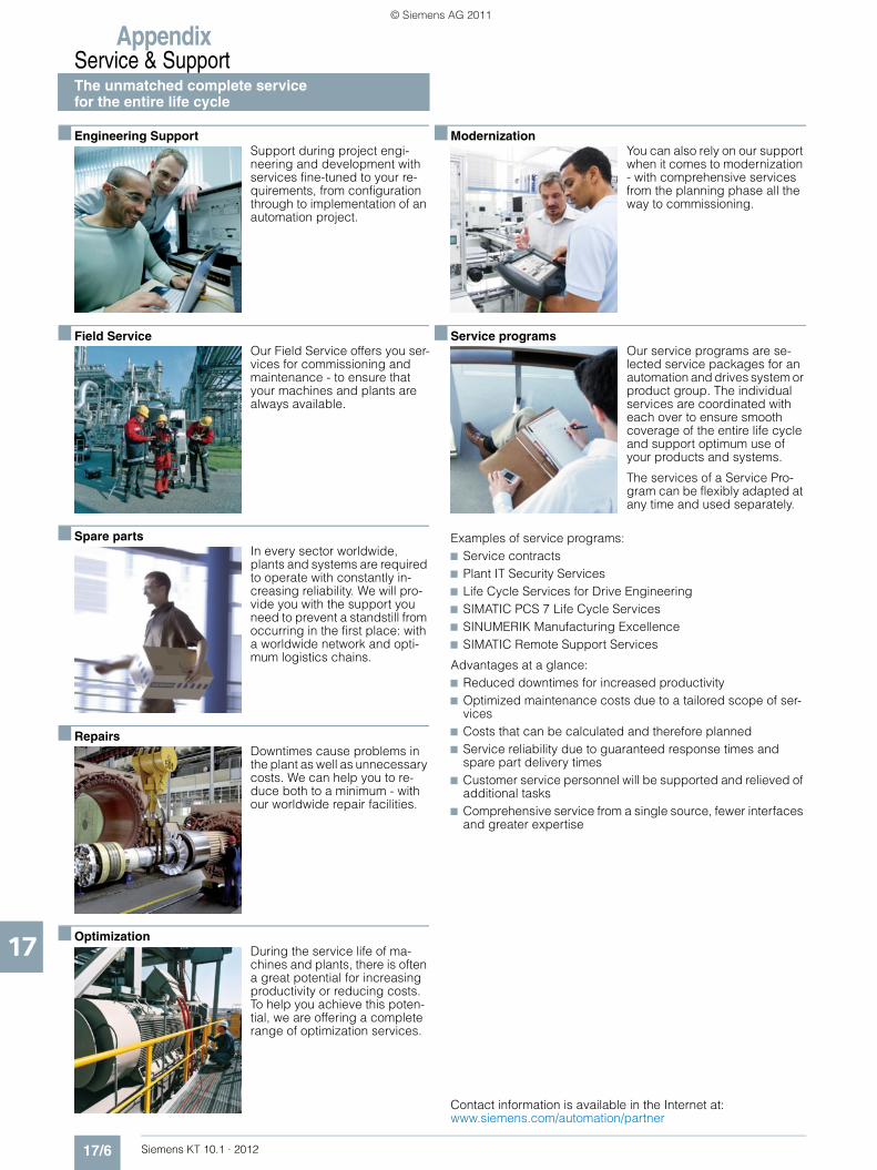
AppendixService & SupportThe unmatched complete service for the entire life cycle
17/6 Siemens KT 10.1 · 2012
17
■ Engineering SupportSupport during project engi-neering and development with services fine-tuned to your re-quirements, from configuration through to implementation of an automation project.
■ Field ServiceOur Field Service offers you ser-vices for commissioning and maintenance - to ensure that your machines and plants are always available.
■ Spare partsIn every sector worldwide, plants and systems are required to operate with constantly in-creasing reliability. We will pro-vide you with the support you need to prevent a standstill from occurring in the first place: with a worldwide network and opti-mum logistics chains.
■ RepairsDowntimes cause problems in the plant as well as unnecessary costs. We can help you to re-duce both to a minimum - with our worldwide repair facilities.
■ OptimizationDuring the service life of ma-chines and plants, there is often a great potential for increasing productivity or reducing costs. To help you achieve this poten-tial, we are offering a complete range of optimization services.
■ ModernizationYou can also rely on our support when it comes to modernization - with comprehensive services from the planning phase all the way to commissioning.
■ Service programsOur service programs are se-lected service packages for an automation and drives system or product group. The individual services are coordinated with each over to ensure smooth coverage of the entire life cycle and support optimum use of your products and systems.
The services of a Service Pro-gram can be flexibly adapted at any time and used separately.
Examples of service programs:7 Service contracts7 Plant IT Security Services7 Life Cycle Services for Drive Engineering7 SIMATIC PCS 7 Life Cycle Services7 SINUMERIK Manufacturing Excellence7 SIMATIC Remote Support Services
Advantages at a glance:7 Reduced downtimes for increased productivity7 Optimized maintenance costs due to a tailored scope of ser-
vices7 Costs that can be calculated and therefore planned7 Service reliability due to guaranteed response times and
spare part delivery times7 Customer service personnel will be supported and relieved of
additional tasks7 Comprehensive service from a single source, fewer interfaces
and greater expertise
Contact information is available in the Internet at: www.siemens.com/automation/partner
KT10_EN_gesamt.book Seite 6 Mittwoch, 12. Oktober 2011 11:00 11
© Siemens AG 2011
AppendixService & Support
17/7Siemens KT 10.1 · 2012
17
■ Knowledge Base on DVD
For locations without online con-nections to the Internet there are excerpts of the free part of the information sources available on DVD (Service & Support Knowl-edge Base). This DVD contains all the latest product information at the time of production (FAQs, Downloads, Tips and Tricks, Up-dates) as well as general infor-mation on Service & Support.
The DVD also includes a full-text search and our Knowledge Manager for targeted searches for solutions. The DVD will be up-dated every 4 months.
Just the same as our online offer in the Internet, the Service & Support Knowledge Base on DVD comes complete in 5 lan-guages (German, English, French, Italian, Spanish).
You can order the Service & Support Knowledge Base DVD from your Siemens contact.
Order no. 6ZB5310-0EP30-0BA2
■ Automation Value Card
Small card - great support
The Automation Value Card is an integral component of the com-prehensive service concept with which Siemens Drive Automa-tion and Drive Technologies will accompany you in each phase of your automation project.
It doesn't matter whether you want just specific services from our Technical Support or want to purchase something on our Online portal, you can always pay with your Automation Value Card. No invoicing, transparent and safe. With your personal card number and associated PIN you can view the state of your account and all transactions at any time.
Services on card. This is how it's done.
Card number and PIN are on the back of the Automation Value Card. When delivered, the PIN is covered by a scratch field, guaranteeing that the full credit is on the card.
By entering the card number and PIN you have full access to the Service & Support services being offered. The charge for the services procured is debited from the credits on your Automa-tion Value Card.
All the services offered are marked in currency-neutral credits, so you can use the Automation Value Card worldwide.
Order your Automation and Value Card easily and comfortably like a product with your sales contact.
Detailed information on the services offered is available on our Internet site at:
www.siemens.com/automation/service&support
Service & Support à la Card: Examples
Automation Value Card order numbers
Credits Order no.
200 6ES7 997-0BA00-0XA0
500 6ES7 997-0BB00-0XA0
1 000 6ES7 997-0BC00-0XA0
10 000 6ES7 997-0BG00-0XA0
Technical Support
”Priority“ Priority processing for urgent cases
”24 h“ Availability round the clock
”Extended“ Technical consulting for complex questions
”Mature Products“
Consulting service for products that are not available any more
Support Tools in the Support Shop
Tools that can be used directly for configuration, anal-ysis and testing
KT10_EN_gesamt.book Seite 7 Mittwoch, 12. Oktober 2011 11:00 11
© Siemens AG 2011
AppendixAlphabetical index
17/8 Siemens KT 10.1 · 2012
17
AAutomation Value Card .............................................................................17/7
BBuffer module SITOP modular ..................................................................11/2
CCircuit diagrams ........................................................................................11/6Class2 version 24 V/3.7 A ...........................................................................4/3Conditions of sale and delivery ...............................................................17/12Configuring notes ......................................................................................16/2Connector for devices in IP65 and IP67 ...................................................14/2
DDC/DC converter .........................................................................................2/3Device labeling plates ..............................................................................14/2
EExport regulations ...................................................................................17/12
FFlat design 24 V/10 A ..................................................................................7/3Flat design 24 V/5 A ....................................................................................5/3
IInstallation notes ......................................................................................16/10International supply voltages and frequencies in low-voltage systems ...16/5
KKnowledge Base on DVD .........................................................................17/7
LLOGO!Power 24 V/1.3 A .............................................................................2/3LOGO!Power 12 V/1.9 A ...........................................................................13/6LOGO!Power 12 V/4.5 A ...........................................................................13/7LOGO!Power 15 V/1.9 A .........................................................................13/12LOGO!Power 15 V/4 A ............................................................................13/12LOGO!Power 24 V/2.5 A .............................................................................3/2LOGO!Power 24 V/4 A ................................................................................4/2LOGO!Power 5 V/3 A ................................................................................13/4LOGO!Power 5 V/6.3 A .............................................................................13/4
MMounting adapter for DIN rail ...................................................................14/2Mounting bracket ......................................................................................14/2Mounting, mounting areas and installation options .................................16/10
OOutdoor version 24 V/2 A.............................................................................2/3Outdoor version 24 V/5 A ............................................................................5/3
PParallel connections for voltage increase ...............................................16/15Parallel connections for performance enhancement ..............................16/14Partners at Industry Automation and Drive Technologies ........................17/2Power connection plug for PSU300P ........................................................14/2PSA100E 24 V/12 A ....................................................................................8/2PSA100E 24 V/2.5 A ...................................................................................3/3PSA100E 24 V/4 A ......................................................................................4/3PSA100E 24 V/6 A ......................................................................................6/2PSU100D 12 V/3 A ....................................................................................13/7PSU100D 24 V/12.5 A .................................................................................8/2PSU100D 24 V/2.1 A ...................................................................................3/3PSU100D 24 V/3.1 A ...................................................................................4/3PSU100D 24 V/4.1 A ...................................................................................4/3PSU100D 24 V/6.2 A ...................................................................................6/2PSU300B 24 V/30 A ..................................................................................10/2PSU300P 24 V/8 A ......................................................................................9/2
RRedundancy module PSE202U ................................................................11/2
SS7-1200 version 24 V/2.5 A ........................................................................3/3S7-200-Type 24 V/3.5 A ..............................................................................4/2S7-300 version 24 V/3 A .............................................................................2/3S7-300 version 24 V/10 A ...........................................................................7/3S7-300 version 24 V/5 A .............................................................................5/3Series connection to increase the voltage ..............................................16/15Signaling module SITOP modular ............................................................11/2Siemens Solution Partner Automation ......................................................17/3SIPLUS extreme ........................................................................................15/2SITOP 1-phase ...........................................................................................2/2SITOP compact PSU100C 12 V/2 A .........................................................13/6SITOP compact PSU100C 12 V/6.5 A ......................................................13/7SITOP compact PSU100C 24 V/0.6 A ........................................................2/2SITOP compact PSU100C 24 V/1.3 A ........................................................2/2SITOP compact PSU100C 24 V/2.5 A ........................................................3/2SITOP compact PSU100C 24 V/4 A ...........................................................4/2SITOP DC/DC 12 V/2.5 A .........................................................................13/6SITOP dual 2 x 15 V/3.5 A ......................................................................13/12SITOP flexi 3-52 V/2-10 A .........................................................................13/2SITOP in SIMATIC-Design ..........................................................................2/3SITOP in SIMATIC-Design 24 V/10 A ..........................................................7/3SITOP in SIMATIC-Design 24 V/2.5 A .........................................................3/3SITOP in SIMATIC-Design 24 V/3.5 A .........................................................4/2SITOP in SIMATIC-Design 24 V/5 A ............................................................5/3SITOP lite PSU100L 24 V/10 A ...................................................................7/3SITOP lite PSU100L 24 V/2.5 A .................................................................. 3/3SITOP lite PSU100L 24 V/5 A .....................................................................5/3SITOP modular 24 V/10 A ....................................................................7/2, 9/2SITOP modular 24 V/20 A ....................................................................8/3, 9/3SITOP modular 24 V/40 A ..................................................................8/3, 10/3SITOP modular 24 V/5 A ......................................................................5/2, 9/2SITOP modular 48 V/20 A .......................................................................13/14SITOP modular PSU100M 24 V/20 A ..........................................................8/2SITOP modular PSU300M 24 V/20 A ..........................................................9/3SITOP modular PSU300M 24 V/40 A ........................................................10/2SITOP modular PSU300M 48 V/10 A ......................................................13/14SITOP modular PSU400M 24 V/20 A ..........................................................8/3SITOP smart 24 V/10 A ...............................................................................7/2SITOP smart 24 V/2.5 A ..............................................................................3/2SITOP smart 24 V/5 A .................................................................................5/2SITOP smart PSU300S 24 V/10 A ...............................................................9/3SITOP smart PSU300S 24 V/20 A ...............................................................9/3SITOP smart PSU300S 24 V/40 A .............................................................10/3Software SITOP DC UPS ..........................................................................12/4Solution Partner Finder .............................................................................17/3Standards and approvals .......................................................................16/20Support .....................................................................................................17/5
UUninterruptible DC power supplies ...........................................................12/2
KT10_EN_gesamt.book Seite 8 Mittwoch, 12. Oktober 2011 11:00 11
© Siemens AG 2011
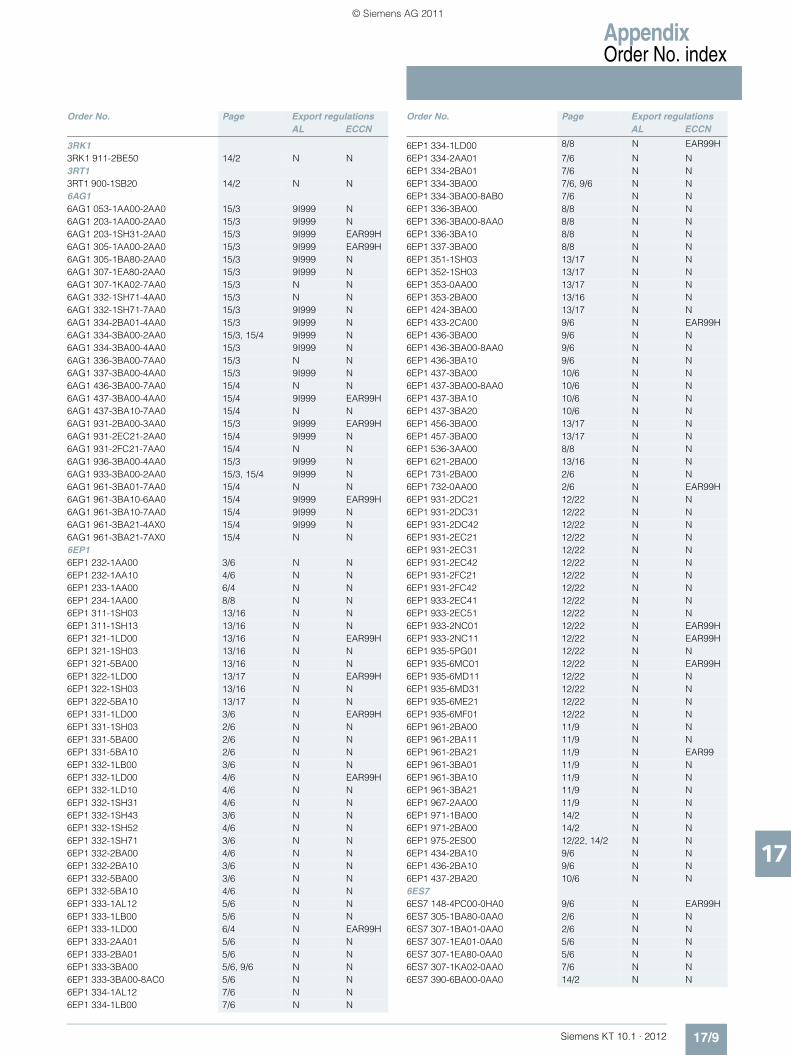
AppendixOrder No. index
17/9Siemens KT 10.1 · 2012
17
Order No. Page Export regulationsAL ECCN
3RK13RK1 911-2BE50 14/2 N N3RT13RT1 900-1SB20 14/2 N N6AG16AG1 053-1AA00-2AA0 15/3 9I999 N6AG1 203-1AA00-2AA0 15/3 9I999 N6AG1 203-1SH31-2AA0 15/3 9I999 EAR99H6AG1 305-1AA00-2AA0 15/3 9I999 EAR99H6AG1 305-1BA80-2AA0 15/3 9I999 N6AG1 307-1EA80-2AA0 15/3 9I999 N6AG1 307-1KA02-7AA0 15/3 N N6AG1 332-1SH71-4AA0 15/3 N N6AG1 332-1SH71-7AA0 15/3 9I999 N6AG1 334-2BA01-4AA0 15/3 9I999 N6AG1 334-3BA00-2AA0 15/3, 15/4 9I999 N6AG1 334-3BA00-4AA0 15/3 9I999 N6AG1 336-3BA00-7AA0 15/3 N N6AG1 337-3BA00-4AA0 15/3 9I999 N6AG1 436-3BA00-7AA0 15/4 N N6AG1 437-3BA00-4AA0 15/4 9I999 EAR99H6AG1 437-3BA10-7AA0 15/4 N N6AG1 931-2BA00-3AA0 15/3 9I999 EAR99H6AG1 931-2EC21-2AA0 15/4 9I999 N6AG1 931-2FC21-7AA0 15/4 N N6AG1 936-3BA00-4AA0 15/3 9I999 N6AG1 933-3BA00-2AA0 15/3, 15/4 9I999 N6AG1 961-3BA01-7AA0 15/4 N N6AG1 961-3BA10-6AA0 15/4 9I999 EAR99H6AG1 961-3BA10-7AA0 15/4 9I999 N6AG1 961-3BA21-4AX0 15/4 9I999 N6AG1 961-3BA21-7AX0 15/4 N N6EP16EP1 232-1AA00 3/6 N N6EP1 232-1AA10 4/6 N N6EP1 233-1AA00 6/4 N N6EP1 234-1AA00 8/8 N N6EP1 311-1SH03 13/16 N N6EP1 311-1SH13 13/16 N N6EP1 321-1LD00 13/16 N EAR99H6EP1 321-1SH03 13/16 N N6EP1 321-5BA00 13/16 N N6EP1 322-1LD00 13/17 N EAR99H6EP1 322-1SH03 13/16 N N6EP1 322-5BA10 13/17 N N6EP1 331-1LD00 3/6 N EAR99H6EP1 331-1SH03 2/6 N N6EP1 331-5BA00 2/6 N N6EP1 331-5BA10 2/6 N N6EP1 332-1LB00 3/6 N N6EP1 332-1LD00 4/6 N EAR99H6EP1 332-1LD10 4/6 N N6EP1 332-1SH31 4/6 N N6EP1 332-1SH43 3/6 N N6EP1 332-1SH52 4/6 N N6EP1 332-1SH71 3/6 N N6EP1 332-2BA00 4/6 N N6EP1 332-2BA10 3/6 N N6EP1 332-5BA00 3/6 N N6EP1 332-5BA10 4/6 N N6EP1 333-1AL12 5/6 N N6EP1 333-1LB00 5/6 N N6EP1 333-1LD00 6/4 N EAR99H6EP1 333-2AA01 5/6 N N6EP1 333-2BA01 5/6 N N6EP1 333-3BA00 5/6, 9/6 N N6EP1 333-3BA00-8AC0 5/6 N N6EP1 334-1AL12 7/6 N N6EP1 334-1LB00 7/6 N N
Order No. Page Export regulations AL ECCN
6EP1 334-1LD00 8/8 N EAR99H
6EP1 334-2AA01 7/6 N N6EP1 334-2BA01 7/6 N N6EP1 334-3BA00 7/6, 9/6 N N6EP1 334-3BA00-8AB0 7/6 N N6EP1 336-3BA00 8/8 N N6EP1 336-3BA00-8AA0 8/8 N N6EP1 336-3BA10 8/8 N N6EP1 337-3BA00 8/8 N N6EP1 351-1SH03 13/17 N N6EP1 352-1SH03 13/17 N N6EP1 353-0AA00 13/17 N N6EP1 353-2BA00 13/16 N N6EP1 424-3BA00 13/17 N N6EP1 433-2CA00 9/6 N EAR99H6EP1 436-3BA00 9/6 N N6EP1 436-3BA00-8AA0 9/6 N N6EP1 436-3BA10 9/6 N N6EP1 437-3BA00 10/6 N N6EP1 437-3BA00-8AA0 10/6 N N6EP1 437-3BA10 10/6 N N6EP1 437-3BA20 10/6 N N6EP1 456-3BA00 13/17 N N6EP1 457-3BA00 13/17 N N6EP1 536-3AA00 8/8 N N6EP1 621-2BA00 13/16 N N6EP1 731-2BA00 2/6 N N6EP1 732-0AA00 2/6 N EAR99H6EP1 931-2DC21 12/22 N N6EP1 931-2DC31 12/22 N N6EP1 931-2DC42 12/22 N N6EP1 931-2EC21 12/22 N N6EP1 931-2EC31 12/22 N N6EP1 931-2EC42 12/22 N N6EP1 931-2FC21 12/22 N N6EP1 931-2FC42 12/22 N N6EP1 933-2EC41 12/22 N N6EP1 933-2EC51 12/22 N N6EP1 933-2NC01 12/22 N EAR99H6EP1 933-2NC11 12/22 N EAR99H6EP1 935-5PG01 12/22 N N6EP1 935-6MC01 12/22 N EAR99H6EP1 935-6MD11 12/22 N N6EP1 935-6MD31 12/22 N N6EP1 935-6ME21 12/22 N N6EP1 935-6MF01 12/22 N N6EP1 961-2BA00 11/9 N N6EP1 961-2BA11 11/9 N N6EP1 961-2BA21 11/9 N EAR996EP1 961-3BA01 11/9 N N6EP1 961-3BA10 11/9 N N6EP1 961-3BA21 11/9 N N6EP1 967-2AA00 11/9 N N6EP1 971-1BA00 14/2 N N6EP1 971-2BA00 14/2 N N6EP1 975-2ES00 12/22, 14/2 N N6EP1 434-2BA10 9/6 N N6EP1 436-2BA10 9/6 N N6EP1 437-2BA20 10/6 N N6ES76ES7 148-4PC00-0HA0 9/6 N EAR99H6ES7 305-1BA80-0AA0 2/6 N N6ES7 307-1BA01-0AA0 2/6 N N6ES7 307-1EA01-0AA0 5/6 N N6ES7 307-1EA80-0AA0 5/6 N N6ES7 307-1KA02-0AA0 7/6 N N6ES7 390-6BA00-0AA0 14/2 N N
KT10_EN_gesamt.book Seite 9 Mittwoch, 12. Oktober 2011 11:00 11
© Siemens AG 2011

Appendix
Notes
17/10 Siemens KT 10.1 · 2012
17
■
KT10_EN_gesamt.book Seite 10 Mittwoch, 12. Oktober 2011 11:00 11
© Siemens AG 2011

Appendix
Notes
17/11Siemens KT 10.1 · 2012
17
■
KT10_EN_gesamt.book Seite 11 Mittwoch, 12. Oktober 2011 11:00 11
© Siemens AG 2011

Appendix
Notes
17/12 Siemens KT 10.1 · 2012
17
■
KT10_EN_gesamt.book Seite 12 Mittwoch, 12. Oktober 2011 11:00 11
© Siemens AG 2011

Appendix
Notes
17/13Siemens KT 10.1 · 2012
17
■
KT10_EN_gesamt.book Seite 13 Mittwoch, 12. Oktober 2011 11:00 11
© Siemens AG 2011

Appendix Conditions of Sale and DeliveryExport regulations
17/14 Siemens KT 10.1 · 2012
17
■ Terms and Conditions of Sale and Delivery
By using this catalog you can acquire hardware and software products described therein from Siemens AG subject to the fol-lowing terms. Please note! The scope, the quality and the condi-tions for supplies and services, including software products, by any Siemens entity having a registered office outside of Ger-many, shall be subject exclusively to the General Terms and Conditions of the respective Siemens entity. The following terms apply exclusively for orders placed with Siemens AG.
For customers with a seat or registered office in GermanyThe “General Terms of Payment” as well as the “General Condi-tions for the Supply of Products and Services of the Electrical and Electronics Industry” shall apply.For software products, the “General License Conditions for Soft-ware Products for Automation and Drives for Customers with a Seat or registered Office in Germany” shall apply.
For customers with a seat or registered office outside of GermanyThe “General Terms of Payment” as well as the “General Condi-tions for Supplies of Siemens, Automation and Drives for Cus-tomers with a Seat or registered Office outside of Germany” shall apply.For software products, the “General License Conditions for Soft-ware Products for Automation and Drives for Customers with a Seat or registered Office outside of Germany” shall apply.
GeneralThe dimensions are in mm. In Germany, according to the Ger-man law on units in measuring technology, data in inches only apply to devices for export. Illustrations are not binding.Insofar as there are no remarks on the corresponding pages, - especially with regard to data, dimensions and weights given - these are subject to change without prior notice.The prices are in € (Euro) ex works, exclusive packaging.The sales tax (value added tax) is not included in the prices. It shall be debited separately at the respective rate according to the applicable legal regulations.Prices are subject to change without prior notice. We will debit the prices valid at the time of delivery.Surcharges will be added to the prices of products that contain silver, copper, aluminum, lead and/or gold if the respective basic official prices for these metals are exceeded. These surcharges will be determined based on the official price and the metal fac-tor of the respective product.The surcharge will be calculated on the basis of the official price on the day prior to receipt of the order or prior to the release order.The metal factor determines the official price as of which the metal surcharges are charged and the calculation method used. The metal factor, provided it is relevant, is included with the price information of the respective products.
An exact explanation of the metal factor and the text of the Com-prehensive Terms and Conditions of Sale and Delivery can be downloaded at:www.siemens.com/automation/salesmaterial-as/catalog/en/terms_of_trade_en.pdf
■ Export regulations
Siemens shall not be obligated to fulfill this agreement if such fulfillment is prevented by any impediments arising out of national or international foreign trade or customs requirements or any embargoes or other sanctions.If you transfer goods (hardware and/ or software and/ or tech-nology as well as corresponding documentation, regardless of the mode of provision) delivered by us or works and services (including all kinds of technical support) performed by us to a third party worldwide, you shall comply with all applicable national and international (re-) export control regulations. If required to conduct export control checks, you, upon request by us, shall promptly provide us with all information pertaining to particular end customer, destination and intended use of goods, works and services provided by us, as well as any export control restrictions existing.The products listed in this catalog / price list may be subject to European / German and/or US export regulations.Therefore, any export requiring a license is subject to approval by the competent authorities.According to current provisions, the following export regulations must be observed with respect to the products featured in this catalog / price list:
Even without a label or with an “AL: N” or “ECCN: N”, authoriza-tion may be required due to the final destination and purpose for which the goods are to be used. The deciding factors are the AL or ECCN export authorization indicated on order confirmations, delivery notes and invoices.Errors excepted and subject to change without prior notice.
AL Number of the German Export ListProducts marked other than “N” require an export license. In the case of software products, the export des-ignations of the relevant data medium must also be generally adhered to.Goods labeled with an “AL“ not equal to “N” are subject to a European or German export authori-zation when being exported out of the EU.
ECCN Export Control Classification NumberProducts marked other than “N” are subject to a reexport license to specific countries.In the case of software products, the exportdesignations of the relevant data medium must also be generally adhered to.Goods labeled with an “ECCN“ not equal to “N” are subject to a US re-export authorization.
KT10_EN_gesamt.book Seite 14 Mittwoch, 12. Oktober 2011 11:00 11
© Siemens AG 2011

CatalogsIndustry Automation, Drive Technologies and Low-Voltage Power Distribution
Further information can be obtained from our branch offices listedin the appendix or at www.siemens.com/automation/partner
Interactive Catalog on DVD Catalogfor Industry Automation, Drive Technologies and Low Voltage Distribution
CA 01
Drive SystemsVariable-Speed DrivesSINAMICS G110, SINAMICS G120 Standard Inverters SINAMICS G110D, SINAMICS G120D Distributed Inverters
D 11.1
SINAMICS G130 Drive Converter Chassis Units SINAMICS G150 Drive Converter Cabinet Units
D 11
SINAMICS GM150, SINAMICS SM150 Medium-Voltage Converters
D 12
SINAMICS S120 Chassis Format Units and Cabinet Modules SINAMICS S150 Converter Cabinet Units
D 21.3
SINAMICS DCM Converter Units D 23.1
Three-phase Induction Motors• H-compact• H-compact PLUS
D 84.1
Asynchronous Motors Standardline D 86.1Synchronous Motors with Permanent-Magnet Technology, HT-direct
D 86.2
DC Motors DA 12SIMOREG DC MASTER 6RA70 Digital Chassis Converters
DA 21.1
SIMOREG K 6RA22 Analog Chassis Converters DA 21.2PDF: SIMOREG DC MASTER 6RM70 Digital Converter
Cabinet UnitsDA 22
SIMOVERT PM Modular Converter Systems DA 45SIEMOSYN Motors DA 48MICROMASTER 420/430/440 Inverters DA 51.2MICROMASTER 411/COMBIMASTER 411 DA 51.3SIMOVERT MASTERDRIVES Vector Control DA 65.10SIMOVERT MASTERDRIVES Motion Control DA 65.11Synchronous and asynchronous servomotors for SIMOVERT MASTERDRIVES
DA 65.3
SIMODRIVE 611 universal and POSMO DA 65.4SIMOTION, SINAMICS S120 and Motors for Production Machines
PM 21
SINAMICS S110 The Basic Positioning Drive
PM 22
Low-Voltage Three-Phase-MotorsIEC Squirrel-Cage Motors D 81.1MOTOX Geared Motors D 87.1
Automation Systems for Machine Tools SIMODRIVE• Motors• Converter Systems SIMODRIVE 611/POSMO
NC 60
Automation Systems for Machine Tools SINAMICS• Motors• Drive System SINAMICS S120
NC 61
Mechanical Driving MachinesFLENDER Standard Couplings MD 10.1FLENDER SIG Standard industrial gear unit MD 30.1
Low-Voltage Power Distribution and Electrical Installation Technology
Protection, Switching, Measuring & Monitoring Devices LV 10.1Switchboards and Distribution Systems LV 10.2GAMMA Building Management Systems ET G1PDF: DELTA Switches and Socket Outlets ET D1SICUBE System Cubicles and Cubicle Air-Conditioning LV 50SIVACON 8PS Busbar Trunking Systems LV 70
PDF: These catalogs are only available as pdf files.
Motion Control Catalog
SINUMERIK & SIMODRIVE Automation Systems for Machine Tools
NC 60
SINUMERIK & SINAMICS Equipment for Machine Tools
NC 61
SINUMERIK 828D BASIC T/BASIC M, SINAMICS S120 Combi and 1FK7/1PH8 motors
NC 82
SIMOTION, SINAMICS S120 and Motors for Production Machines
PM 21
SINAMICS S110 The Basic Positioning Drive
PM 22
Drive and Control Components for Cranes CR 1
Power Supply and System CablingPower supply SITOP KT 10.1System cabling SIMATIC TOP connect KT 10.2
Process Instrumentation and AnalyticsField Instruments for Process Automation FI 01SIREC Recorders and Accessories MP 20SIPART, Controllers and Software MP 31Products for Weighing Technology WT 10PDF: Process Analytical Instruments PA 01PDF: Process Analytics,
Components for the System IntegrationPA 11
Safety IntegratedSafety Technology for Factory Automation SI 10
SIMATIC HMI/PC-based AutomationHuman Machine Interface Systems/PC-based Automation
ST 80/ ST PC
SIMATIC IdentIndustrial Identification Systems ID 10
SIMATIC Industrial Automation SystemsProducts for Totally Integrated Automation and Micro Automation
ST 70
SIMATIC PCS 7 Process Control System ST PCS 7Add-ons for the SIMATIC PCS 7 Process Control System
ST PCS 7.1
PDF: Migration solutions with the SIMATIC PCS 7 Process Control System
ST PCS 7.2
SIMATIC NETIndustrial Communication IK PI
SINVERT PhotovoltaicsInverters and Components for Photovoltaic Installations RE 10
SIRIUS Industrial Controls SIRIUS Industrial Controls IC 10SIRIUS Industrial Controls (selected content from catalog IC 10)
IC 90
System SolutionsApplications and Products for Industry are part of the interactive catalog CA 01
Download-Center
PDF versions of the catalogs are available on the Internet at:www.siemens.com/automation/infocenter
KT10_EN_gesamt.book Seite 2 Mittwoch, 12. Oktober 2011 11:00 11
© Siemens AG 2011

The information provided in this catalog contains descriptions or characteristics of performance which in case of actual use do not always apply as described or which may change as a result of further development of the products. An obligation to provide the respective characteristics shall only exist if expressly agreed in the terms of contract. Availability and technical specifications are subject to change without notice.All product designations may be trademarks or product names of Siemens AG or supplier companies whose use by third parties for their own purposes could violate the rights of the owners.www.siemens.com/sitop
Subject to change without prior noticeOrder No. E86060-K2410-A111-A8-7600MP.R1.SC. PPKG. 68.2.01 / Dispo 10001KG 1111 6. AUM 160 EnPrinted in Germany © Siemens AG 2011
Siemens AGIndustry SectorIndustry Automation DivisionSensors and CommunicationPostfach 48 4890026 NÜRNBERGGERMANY
Umschlag_Katalog_KT10_1_2012_en.indd 1Umschlag_Katalog_KT10_1_2012_en.indd 1 17.10.2011 17:34:3317.10.2011 17:34:33
© Siemens AG 2011