
sites.ntc.doe.gov · Web viewCourse: SBA-130DE, Accident Analysis and Control Selection Lesson 1:...
269
Course: SBA-130DE, Accident Analysis and Control Selection Lesson 1: Accident Analysis Script Storyboard By signing this page, the authorizing parties agree to the overall course content, structure, and assessments described in this script storyboard. document.docx 1/22/2016 Page 1 of 269 Invalid signature X Regina Floyd InstructionalD esigner Signed by:D epartm entofEnergy X SM E 1/25/2016 X W alterMeeks Curriculum M anager Signed by:D epartm entofEnergy 1/25/2016 X Rob Adelm an eL Team Lead Signed by:RO BERT AD ELM AN (Affiliate) Invalid signature X M ark W . M iller Training D epartm entM anager Signed by:M ARK M ILLER (Affiliate) Invalid signature X AlbertM acD ougall DO E Authorizing Signature Signed by:AlbertE.M acdougall
Transcript of sites.ntc.doe.gov · Web viewCourse: SBA-130DE, Accident Analysis and Control Selection Lesson 1:...
Course: SBA-130DE, Accident Analysis and Control SelectionLesson 1: Accident Analysis
Script Storyboard
By signing this page, the authorizing parties agree to the overall course content, structure, and assessments described in this script storyboard.
document.docx 1/22/2016 Page 1 of 204
Invalid signature
X Regina FloydInstructional Designer
Signed by: Department of Energy
XSME
1/25/2016
X Walter MeeksCurriculum Manager
Signed by: Department of Energy1/25/2016
X Rob AdelmaneL Team Lead
Signed by: ROBERT ADELMAN (Affiliate)
Invalid signature
X Mark W. MillerTraining Department Manager
Signed by: MARK MILLER (Affiliate)
Invalid signature
X Albert MacDougallDOE Authorizing Signature
Signed by: Albert E. Macdougall

Lesson/Objective Objective # and Objective from Design Document Slide # Slide NumberSlide Content Screen Type Screen Type/Layout
The content in this area appears on the screen/slide.
Narration
The content in this area is narrated (audio).
Programming Instructions
This area contains programming instructions.
Feedback Instructions
This area contains learner feedback for assessments/activities.
Media Instructions
This area contains media (video/animation/graphics) instructions.
document.docx 1/22/2016 Page 2 of 204

LMS Information
Details Tab Settings TabTitle SBA-130DE, Accident Analysis and Control Selection Required Grade 80%External Title SBA-130DE Course Length (mins) 240Description TBD Audience DOE Nuclear Safety Specialists (NSS) and safety
basis analystsGoals TBD
Certificate (Y/N?) Y Prerequisites Tab
Prerequisites SBA-120DE
document.docx 1/22/2016 Page 3 of 204

Acronyms for Glossary
Acronym DefinitionARF Airborne respirable fractionBR Breathing rateCFR Code of Federal RegulationsDBA Design basis accidentDCF Dose conversion factorDR Damage ratioDSA Documented Safety AnalysisDSTR Dose to source term ratioEBA Evaluation basis accidentEG Evaluation guidelineHA Hazard analysisHEPA High efficiency particulate airLPF Leak path factorMAR Material at riskMOI Maximally exposed offsite individualNPH Natural phenomena hazardNSS Nuclear Safety SpecialistPDSA Preliminary Documented Safety AnalysisPRA Probabilistic risk assessmentRF Respirable fractionSAC Specific administrative controlSAR Safety Analysis ReportSC Safety classSIH Standard industrial hazardSS Safety significantSSC Structures, systems, and componentsST Source termTSL Technical support levelTSR Technical safety requirement
document.docx 1/22/2016 Page 4 of 204

Lesson/Objective NA Slide #Slide Content Screen Type Title
Narration
<Narrator>Welcome to SBA-130DE, Accident Analysis and Control Selection. The purpose of this course is to provide DOE nuclear safety specialists and safety basis analysts with the fundamental knowledge associated with accident analysis and control selection.
Programming Instructions
Media Instructionssba130_01_00_01.mp3
document.docx 1/22/2016 Page 5 of 204
SBA-130DEAccident Analysis and Control Selection

Lesson/Objective NA Slide #Slide Content Screen Type
Navigation Instructions
Narration<Narrator> Review the navigation instructions before continuing.Programming Instructions
Media Instructions
document.docx 1/22/2016 Page 6 of 204

Lesson/Objective NA Slide #Slide Content Screen Type
Course StructureSelect each lesson to view the subtopics.
Narration <Narrator> This course directly supports the Nuclear Safety Specialist qualification. It consists of four lessons, each of which is organized into several topics.Programming InstructionsWhen user selects lesson, show info below:
Lesson 1: Accident AnalysisAfter completing this lesson, you will be able to select design basis accidents (DBAs) and evaluation basis accidents (EBAs) and perform radiological source term and dose calculations. This lesson will take you approximately 2 hours to complete.
Lesson 2: Control SelectionAfter completing this lesson, you will be able to identify the processes and requirements that contractors must use during control selection. This lesson will take you approximately 45 minutes to complete.
Lesson 3: Criticality Safety and SMPsAfter completing this lesson, you will be able to identify the requirements that contractors must use when documenting criticality safety and safety management programs. This lesson will take you approximately 30 minutes to complete.
Lesson 4: Beyond Design/Evaluation Basis AccidentsAfter completing this lesson, you will be able to identify the requirements that contractors must adhere to when documenting beyond design basis accidents (BDBAs) and beyond evaluation basis accidents (BEBAs). This lesson will take you approximately 20 minutes to complete.
Practical AssessmentThe purpose of the practical assessment is to evaluate your knowledge of the accident analysis and control selection process. The practical assessment will take you approximately 30 minutes to complete. Media Instructionssba130_01_00_02.mp3
document.docx 1/22/2016 Page 7 of 204

Lesson/Objective NA Slide #Slide Content Screen Type
Course Goals and ObjectivesThe goal of this course is to introduce you to the processes and requirements associated with the accident analysis and control selection process.
After completing this course, you will be able to:
Identify the processes, factors, and documentation associated with calculation of the source term and dose. Identify the processes, requirements, and documentation associated with control selection. Identify the requirements for documenting criticality safety and safety management programs. Identify the processes, requirements, and documentation required for the evaluation of beyond design basis accidents (BDBAs) and
beyond evaluation basis accidents (BEBAs).
Specific objectives are detailed in each lesson. Narration <Narrator> The goal of this course is to introduce you to the processes and requirements associated with the accident analysis and control selection process.Programming Instructions
Media Instructionssba130_01_00_03.mp3
document.docx 1/22/2016 Page 8 of 204

Lesson/Objective NA Slide #Slide Content Screen Type
Course Completion and Credit
You must meet the following requirements to receive credit.
View all pages Complete all activities, knowledge checks, and practical assessments Pass all assessments with a score of 80% or higher Complete the NTC Student Feedback Form
You will receive two attempts for each knowledge check. You will have the opportunity to retry the knowledge checks after completing each topic (if you score below 80%).
If you need to stop before completing the course, close the browser window. The NTC’s Learning Management System (LMS) will report that the course is “In Progress” and will bookmark your place. When you return, select the “Resume” option and the course will open to your last viewed page.
When you have satisfied the requirements of this course, the NTC LMS will automatically log your completion and add the completed course to your transcript. You can access your certificate from the Transcript tab, and print it out or email it to your training point of contact or supervisor.Narration<Narrator> You must meet the following requirements to receive credit. Be sure to review the requirements carefully before continuing.
Programming Instructions
Media Instructions
document.docx 1/22/2016 Page 9 of 204

Lesson/Objective Outline the process for performing an accident analysis. Slide #Slide Content Screen Type
Accident Analysis
ID # Event Type
Scenario Initiating Event or Cause Description Likelihood Consequence Risk NotesP CW W P CW W
F-02 Fire Any ignition source (e.g., power tools or hotwork) ignites combustibles in the glovebox.
Fire consumes rubber gloves or breaches HEPA filters or ductwork, causing loss of confinement. Potential for direct release path to exterior of building
Uncontrolled U H H H I I I MAR – 1 container (800 PE-Ci)
Controlled EU M M M III III IIIBuilding confinement ventilation system
Building structural integrity Combustible loading program
Emergency Preparedness Program
Building and glovebox fire suppression system
document.docx 1/22/2016 Page 10 of 204

Glovebox design integrity and confinement
Narration<Bob> As a nuclear safety specialist, you will determine the adequacy of a contractor’s accident analysis methodology and documentation. To get you up to speed, we’re going to spend this week walking through the accident analysis and control selection process.
Let’s start by reviewing where we are in the process. As I’m sure you remember, we’re following the tasks listed in DOE-STD-3009. We’re going to focus on performing the accident analysis, selecting the hazard controls, describing the hazard controls, and deriving the technical safety requirements.
During your previous visit at the VERB, the team identified, categorized, and evaluated the hazards using the methodologies in DOE-STD-3009 and DOE-STD-1027. One of the outputs of that process was the Hazard Evaluation Table listing the initiating event, likelihood, consequence, risk, and controls for each hazard scenario. The hazard scenarios in the Hazard Evaluation Table are our starting point for the accident analysis.Programming Instructions
Media Instructionssba130_01_00_04.mp3
document.docx 1/22/2016 Page 11 of 204

Lesson/Objective Outline the process for performing an accident analysis. Slide #Slide Content Screen Type
Accident Analysis Process Overview
Select each step to learn more.
1 Select Design/Evaluation Basis Accidents
During the accident analysis, only a limited subset of the hazard scenarios documented during the hazard evaluation are selected for evaluation. The selected accidents are referred to as design basis accidents (or DBAs) and evaluation basis accidents (or EBAs).
Selecting DBA/EBAs includes the following substeps:
1. Categorizing accidents into three categories: operational accidents, natural events, and man-made external events2. Grouping accidents by event type, environmental accident conditions, and controls3. Selecting a representative bounding accident from each group 4. Identifying unique accidents based on control sets or environmental accident conditions5. Screening accidents from selection using Section 3.2.1 of DOE-STD-30096. Documenting selection of DBAs/EBAs in Section 3.4.3.X of the DSA
2 Develop Formal Descriptions
This process documents the accident progression from the initiating event through all subsequent events and includes the following substeps:
1. Determining inputs, assumptions, and initial conditions2. Determining accident phenomena3. Identifying accident progression (linking initiating events to preventive and mitigative controls)4. Identifying accident stresses and resulting forces5. Identifying damage to effected equipment, containments, and structures6. Documenting scenario development per Section 4 of DOE-STD-3009
3 Calculate Source Term
This process involves calculating the unmitigated source term for the selected DBAs/EBAs:
1. Determining material at risk (MAR)2. Determining damage ratio (DR)3. Determining airborne release fraction (ARF)4. Determining release fraction (RF)
document.docx 1/22/2016 Page 12 of 204

5. Determining leakpath factor (LPF)6. Calculating source term
4 Calculate Radiological Dose and Consequences
This process involves calculating the unmitigated radiological dose and consequences for the selected DBAs/EBAs:
1. Determining X/Q2. Identifying breathing rate (BR)3. Determining dose conversion factor (DCF)4. Calculating dose
Note: This course focuses on calculating the radiological dose and consequences. For information on calculating chemical dose and consequences, refer to DOE-STD-3009 and DOE-HDBK-xxxx.
5 Compare Consequence Estimate to the EG and/or Co-located Worker Threshold
This step involves comparing the consequence estimates to the EG for the public and/or co-located worker threshold (in Table 1 of DOE-STD-3009).
Each DBA/EBA is evaluated based on the following criteria: Unmitigated radiological public consequences having the potential to challenge (> 5 rem to < 25 rem) or exceed (> 25 rem)
the evaluation guideline (EG) Unmitigated radiological co-located worker consequences having the potential to exceed 100 rem at 100 meters Unmitigated chemical consequences to the public and co-located worker that exceed the criteria in Section 3.3.2 of DOE-
STD-3009
Accident scenarios meeting the criteria are carried forward to the mitigated accident analysis (control selection) process.
Narration<Bob> Here’s an overview of the accident analysis process.Programming Instructions
Media Instructionssba130_01_00_05.mp3
document.docx 1/22/2016 Page 13 of 204

Lesson/Objective NA Slide #Slide Content Screen Type
Lesson ObjectivesAfter completing this lesson, you will be able to:
Identify the purpose and scope of an accident analysis. Outline the process for performing an accident analsyis. Select design basis accidents (DBAs)/evaluation basis accidents (EBAs) for an accident analysis. Calculate the source term based on derived inputs. Calculate the dose consequence based on the X/Q value. Identify the factors that should be considered when calculating source term and dose. Determine if a mitigated evaluation is required based on a comparison of consequence to the evaluation guideline (EG) for public
protection and/or the co-located worker threshold. Identify the requirements for documenting an accident analysis.
Narration Programming Instructions
Notes
document.docx 1/22/2016 Page 14 of 204

Lesson/Objective NA Slide #Slide Content Screen Type Menu
Menu
Purpose and Scope
Selecting DBAs/EBAs
Developing Formal Descriptions
Calculating Radiological Source Term
Calculating Radiological Dose
Comparing Consequence Estimates to the EG and/or CW Threshold
Narration
Programming Instructions
Media Instructions
document.docx 1/22/2016 Page 15 of 204
This lesson will be split into 2 lessons:
Accident Analysis – Part 1 will cover the following sections:
Purpose and Scope
Selecting DBAs/EBAs
Developing Formal Descriptions
Accident Analysis – Part 2 will cover the remaining sections.

Lesson/Objective Identify the purpose and scope of an accident analysis. Slide #Slide Content Screen Type
Purpose and Scope10 CFR 830.204
(b) The documented safety analysis for a hazard category 1, 2, or 3 DOE nuclear facility must, as appropriate for the complexities and hazards associated with the facility:...
(3) Evaluate normal, abnormal, and accident conditions, including consideration of natural and man-made external events, identification of energy sources or processes that might contribute to the generation or uncontrolled release of radioactive and other hazardous materials, and consideration of the need for analysis of accidents which may be beyond the design basis of the facility
DOE-HDBK-xxxx…the purpose of accident analysis is develop a comprehensive set of hazard controls to evaluate the need for safety class controls to protect the public. However, it may also be used to evaluate the need for safety-significant controls for protection of the public or co-located workers. DOE-STD-3009…accident analysis entails the formal characterization of a limited subset of accidents and the determination of consequences and hazard controls associated with those events. Accident analysis is not necessary for facilities with unmitigated offsite consequences that do not have the potential to challenge the EG. DOE-STD-3009For the purposes of identifying safety class (SC) SSCs, estimated consequences to the MOI are compared to the evaluation guideline (EG)… For the purpose of identifying SS SSCs, an evaluation of co-located worker consequences and offsite chemical consequences is also required and is performed as part of either: the hazard evaluation…or the accident analysis. Narration<Bob> According to 10 CFR 830.204, the DSA must evaluate the normal, abnormal, and accident conditions that might contribute to the generation or uncontrolled release of radioactive and other hazardous materials. We also need to consider the need for analysis of accidents that may be beyond the design basis for the facility.
According to DOE-HDBK-xxxx, Hazard and Accident Analysis Handbook, the purpose of accident analysis is develop a comprehensive set of hazard controls to evaluate the need for safety class controls to protect the public. However, accident analysis may also be used to evaluate the need for safety-significant controls for protection of the public or co-located workers.
According to DOE-STD-3009, accident analysis entails the formal characterization of a limited subset of accidents and the determination of consequences and hazard controls associated with those events. Also, accident analysis is not necessary for facilities with unmitigated offsite consequences that do not have the potential to challenge the EG.
To identify safety class SSCs, estimated consequences to the public are compared to the EG. For the purpose of identifying safety significant
document.docx 1/22/2016 Page 16 of 204

SSCs, an evaluation of co-located worker consequences and offsite chemical consequences is also required and can be performed as part of accident analysis.Programming Instructions
Media Instructionssba130_01_01_01.mp3
document.docx 1/22/2016 Page 17 of 204

Lesson/Objective Identify the purpose and scope of an accident analysis. Slide #Slide Content Screen Type
SC and SS ControlsSelect each type of control to learn more.
Safety Class
Section 3.3.1 – Safety Class (SC) Controls for Public Protection
If the unmitigated release consequence for a DBA/EBA exceeds the EG (> 25 rem), safety class controls shall be applied to prevent the accident or mitigate the consequences to below the EG.
If unmitigated off-site doses are calculated to be between 5 rem and 25 rem, then the dose challenges the EG and safety class controls should be considered. The rationale should be described on whether or not to classify controls as safety class.
Safety Significant
Section 3.3.2 – Safety Significant (SS) Controls for Public and Co-located Worker Protection
Controls that provide a major contribution to defense-in-depth shall be designated as safety significant.
Safety significant controls providing protection to the public from chemicals shall be based on a peak 15 minute time-weighted average air concentration, measured at the receptor location that exceeds PAC-2.
Safety significant controls providing protection to the co-located worker from radiological release shall be based on an unmitigated dose of 100 rem total effective dose (TED) to a receptor located at 100 meters. Also, it shall be based on a peak 15 minute time-weighted average air concentration at the receptor location that exceeds PAC-3 for chemical releases.
For additional information on defense-in-depth, refer to DOE-STD-3009-2014, Appendix A.9.
document.docx 1/22/2016 Page 18 of 204
Narration<Bob> Let’s take a closer look at how the estimated consequences are used to identify safety class and safety significant SSCs for both the public and the co-located worker. Sections 3.3.1 and 3.3.2 of DOE-STD-3009 identify the criteria for designating controls as either safety class or safety significant. Programming Instructions
Media Instructionssba130_01_01_02.mp3
document.docx 1/22/2016 Page 19 of 204

Lesson/Objective NA Slide #Slide Content Screen Type
Accident Analysis TermsDown
1. The first event in a sequence of events in an accident.
2. The process of deriving a set of formalized design/evaluation basis accidents from the hazard evaluation and determining their consequences.
Across
3. The amount of respirable radioactive or other hazardous material that is released as a result of the postulated accident scenario.
4. The accident with the highest consequences among a group of similar accidents.
5. The criterion established for the purpose of identifying and evaluating the effectiveness of needed safety class SSCs
Reveal
Narration<Bob> While I gather all the information we’ll need for today, why don’t you see if you can solve this puzzle?
<Bob Feedback> It looks like you’re already familiar with some of the terms associated with accident analysis!Feedback Instructions Immediate visual feedback Media Instructionssba130_01_01_03.mp3sba130_01_01_04.mp3
document.docx 1/22/2016 Page 20 of 204

Lesson/Objective NA Slide #Slide Content Screen Type
Purpose and Scope Knowledge Check
Which of the following is the purpose and scope of the accident analysis process? Select all that apply.
Identifying SC SSCs based on unmitigated radiological consequences to the public that have the potential to challenge or exceed the EG
Identifying SC SSCs based on unmitigated chemical consequences to the public
Identifying SS SSCs based on unmitigated radiological consequences to the co-located worker that have the potential to exceed 100 rem at 100 meters
Identifying SS SSCs based on unmitigated chemical consequences to the public and co-located worker
Identifying SS SSCs based on unmitigated radiological and chemical consequences to the facility worker
DOE-STD-3009
Feedback goes here
Narration
Feedback InstructionsTry again. Refer to Section 3.3.1 and Section 3.3.2 in DOE-STD-3009. Incorrect. The purpose and scope of the accident analysis is to identify 1) SC SSCs based on unmitigated radiological consequences to the public that have the potential to challenge or exceed the EG, 2) SS SSCs based on unmitigated radiological consequences to the co-located worker that have the potential to exceed 100 rem at 100 meters, and 3) SS SSCs based on unmitigated chemical consequences to the public and co-located worker.Correct.Media Instructions
document.docx 1/22/2016 Page 21 of 204
Submit

Lesson/Objective NA Slide #Slide Content Screen Type Menu
Purpose and Scope
Selecting DBAs/EBAs
Developing Formal Descriptions
Calculating Radiological Source Term
Calculating Radiological Dose
Comparing Consequence Estimates to the EG and/or CW Threshold
Narration
Programming Instructions
Media Instructions
document.docx 1/22/2016 Page 22 of 204

Lesson/Objective NA Slide #Slide Content Screen Type Submenu
Selecting DBAs/EBAs ProcessSelect each step to learn more.
Narration<Bob> The first step in the accident analysis process is selecting the scenarios from the Hazard Evaluation Tables to carry forward into the accident analysis. We’re going to start by categorizing all the scenarios and then grouping the accidents by event type, controls, and accident environment conditions. Then we’ll select both representative and unique accidents for each group. We’ll screen the accidents using the criteria in DOE-STD-3009 and then document the selection. Programming Instructions
Media Instructionssba130_01_02_01.mp3
document.docx 1/22/2016 Page 23 of 204
Lesson/Objective Select design basis accidents (DBAs)/evaluation basis accidents (EBAs) for an accident analysis. Slide #Slide Content Screen Type
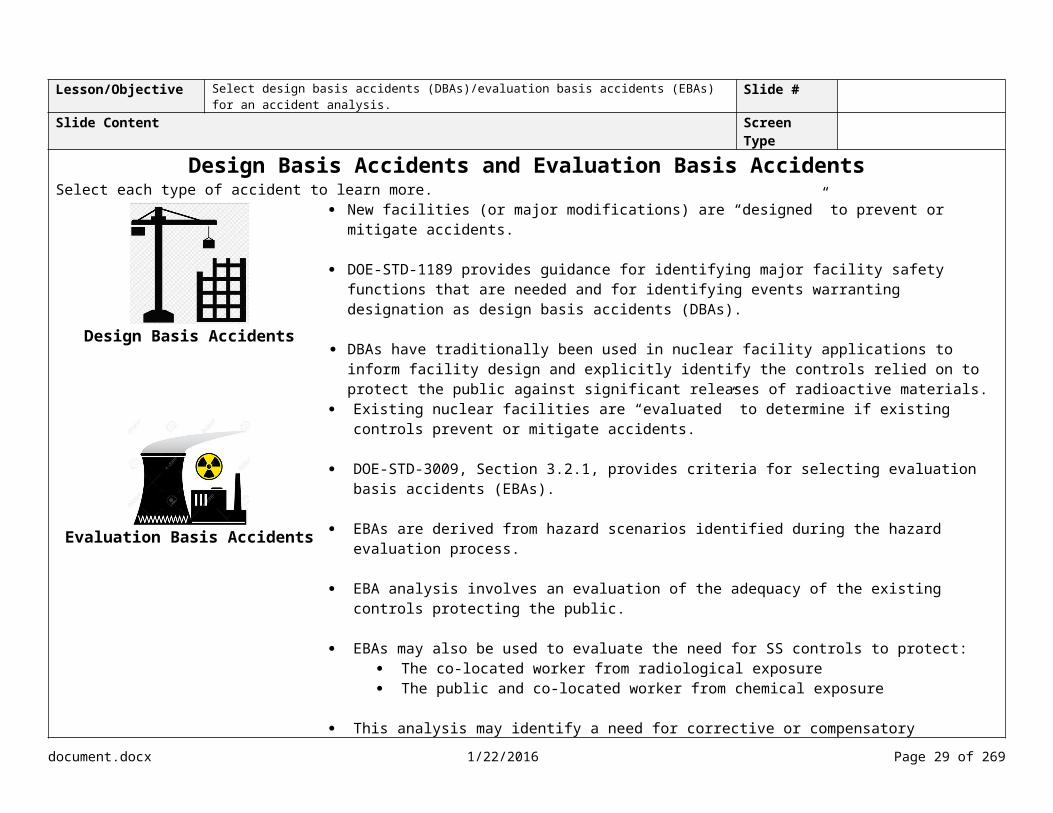
Design Basis Accidents and Evaluation Basis AccidentsSelect each type of accident to learn more.
Design Basis Accidents
New facilities (or major modifications) are “designed” to prevent or mitigate accidents.
DOE-STD-1189 provides guidance for identifying major facility safety functions that are needed and for identifying events warranting designation as design basis accidents (DBAs).
DBAs have traditionally been used in nuclear facility applications to inform facility design and explicitly identify the controls relied on to protect the public against significant releases of radioactive materials.
Evaluation Basis Accidents
Existing nuclear facilities are “evaluated” to determine if existing controls prevent or mitigate accidents.
DOE-STD-3009, Section 3.2.1, provides criteria for selecting evaluation basis accidents (EBAs).
EBAs are derived from hazard scenarios identified during the hazard evaluation process.
EBA analysis involves an evaluation of the adequacy of the existing controls protecting the public.
EBAs may also be used to evaluate the need for SS controls to protect: The co-located worker from radiological exposure The public and co-located worker from chemical exposure
This analysis may identify a need for corrective or compensatory measures in the form of SC or SS systems, structures, and components (SSCs).
Narration<Bob> During the accident analysis, we select only a limited subset of the hazard scenarios documented during the hazard evaluation. The selected accidents are referred to as design basis accidents and evaluation basis accidents. We’re going to focus on EBAs. Let’s take a look at the differences between DBAs and EBAs.Programming Instructions According to Section 4 of DOE-STD-3009, Section 3.4.2 of the DSA, DBAs/EBAs may be identified for other accidents if not quantitatively evaluated in the hazard evaluation and included in Section 3.3.2.3 of the DSA. Examples include radiological exposures to the co-located worker or chemical exposures to the public and co-located worker. Media Instructionssba130_01_02_02.mp3Lesson/Objective Select design basis accidents (DBAs)/evaluation basis accidents (EBAs) for an accident analysis. Slide #
document.docx 1/22/2016 Page 24 of 204

Slide Content Screen Type
Categorizing Accidents ActivityDrag and drop the accident type to the hazard scenario.
Event Type Scenario Initiating Event or Cause
Nuclear Criticiality
Improper stacking of high fissile gram equivalent drums causes inadvertent criticality
Waste containers with signficant fissionable material are stacked in a configuration that causes a criticality
Operational Accident
Loss of Containment/Confinement
Forklift tine punctures or cylinder or vehicle impacts TRU waste container
Forklift, damaged cylinder, or vehicle impacts TRU waste container during handling
Operational Accident
Fire Furnace temperature excursion, combustibles adjacent to furnace, fire inside glovebox, and glovebox breach
Furnace malfunction
Operational Accident
External Event
Fire spreads impacting TRU waste containers
Vehicle (not facility related) or refueling truck accident adjacent to site causes fuel leak and spreads throughout facility
Man-Made External Event
External Event
Aircraft crash Aircraft crashes into staging area or building causing a full facility (inside and outside) fire
Man-Made External Event
Natural Phenomena
Grass/brush fire in fields impacts TRU waste containers
Wildfire adjacent to site Natural Phenomena Event
Natural Phenomena
Ignition of combustibles impacts TRU waste containers staged outside (potential for fire to spread to the building)
Lightening causes fire in yard and/or container
Natural Phenomena Event
Natural Phenomena
TRU waste containers toppled by seismic event and impacted by fire
Seismic event initiates a facility-wide fire
Natural Phenomena Event
Fire Drum contents ignite, spreading fire to combustibles, impacting the glovebox confinement
Pyrophoric, flammable (including combustible) liquid, gas, or oxidizer material ignites, or spontaneous combustion causes fire
Operational Accident
Explosion Explosion breaches waste containers and contents burn
Vehicle accident results in fuel leak and fuel tank explosion
Man-Made External Event
Direct Exposure
Worker exposed to penetrating radiation
Unexpected radioactive source is removed from waste containers
Operational Accident
Narration
document.docx 1/22/2016 Page 25 of 204
Operational Accident
Natural Phenomena Event
Man-Made External Event

<Bob> In order to select the EBAs, we need to categorize the accidents. According to Section 3.2.1 of DOE-STD-3009, when an adequate set of DBAs does not exist, we need to select the EBAs from three categories: operational accidents, natural events, and man-made external events.
We need to ensure that the EBAs are derived from the full spectrum of hazard scenarios developed during the hazard evaluation. You should be familiar with operational accidents, natural events, and man-made external events from the hazard identification and evaluation, so why don’t you try categorizing some of the hazard scenarios?
<Bob Feedback> As you can see, operational accidents result from process deviations (such as the criticality caused by improper stacking of the drums or hot work in the glovebox) or initiating events internal to the facility (such as the forklift impacting the waste containers). Natural phenomena events include events such as the seismic event, wildfire, and lightning. Man-made external events include events such as the aircraft crash and refueling truck accident adjacent to the site. Programming InstructionsSplit into three slidesImmediate visual feedbackMedia Instructionssba130_01_02_03.mp3sba130_01_02_04.mp3
document.docx 1/22/2016 Page 26 of 204

Lesson/Objective NA Slide #Slide Content Screen Type
Selecting DBAs/EBAs ProcessSelect each step to learn more.
Narration
Programming Instructions
Media Instructions
document.docx 1/22/2016 Page 27 of 204

Lesson/Objective Select design basis accidents (DBAs)/evaluation basis accidents (EBAs) for an accident analysis. Slide #Slide Content Screen Type
Grouping Accidents by Event TypeSelect each event type to learn more.
Fire
Fire contributes to the airborne release of radiological material directly through entrainment into the buoyant plume or indirectly by converting material into particulate matter through the burning process.
“Fire generates heat and combustion gases that may destroy/stress the radioactive material and/or the substrate upon which radioactive materials may be deposited, compromise barriers, and/or pressurize containers/enclosure that may lead to the airborne release of contained radioactive materials. Mass flux of vapors from the reacting surfaces suspend material in air. This material is then entrained in general convective currents that provide transport for particulate materials.” DOE-HDBK-3010-94
There are several types of fire that should be considered for analysis.
Fuel Pool FireThe analysis of liquid fuel fires, separate from other fires, is important because liquid fuel fires have the potential to result in pool fires that have a substantially higher source term than combustible material fires when waste containers are involved in the event.
Small Fire This type of fire is limited in size and is contained within a fire area.
Enclosure Fire This type of fire occurs in a specified enclosure such as a glovebox or hot cell. Analysis of this type of fire is necessary due to the potential for unique ignition hazards and material at risk (MAR).
Large FireThis type of fire represents an event that propagates beyond a single fire area. The configuration of a large fire is dependent on the facility configuration (e.g., a large, multi-level facility may have a room fire, a level fire, and a full-facility fire).
It is usually necessary to understand the unmitigated fire potential in terms of heat release rate (HRR), which is the rate at which heat is generated by fire. The HRR can be viewed as the engine driving the fire. HRR is measured in joules per second (also called Watts). Since a fire puts out much more than 1 Watt, HRR is typically quantified in Kilowatts (1000 Watts) or megawatts (a million watts).
The size of the fire analyzed within the DSA will be dependent on assumptions addressed in the Fire Hazard Analysis (FHA). The facilities FHA should serve as the basic input to the DSA fire scenario development and any fire analysis performed to support the DSA. As directed by DOE O 420.1C, the FHA “…must be integrated into safety basis documentation.”
For additional information and examples of fire event types and scenarios, refer to DOE-HDBK-xxxx.
document.docx 1/22/2016 Page 28 of 204
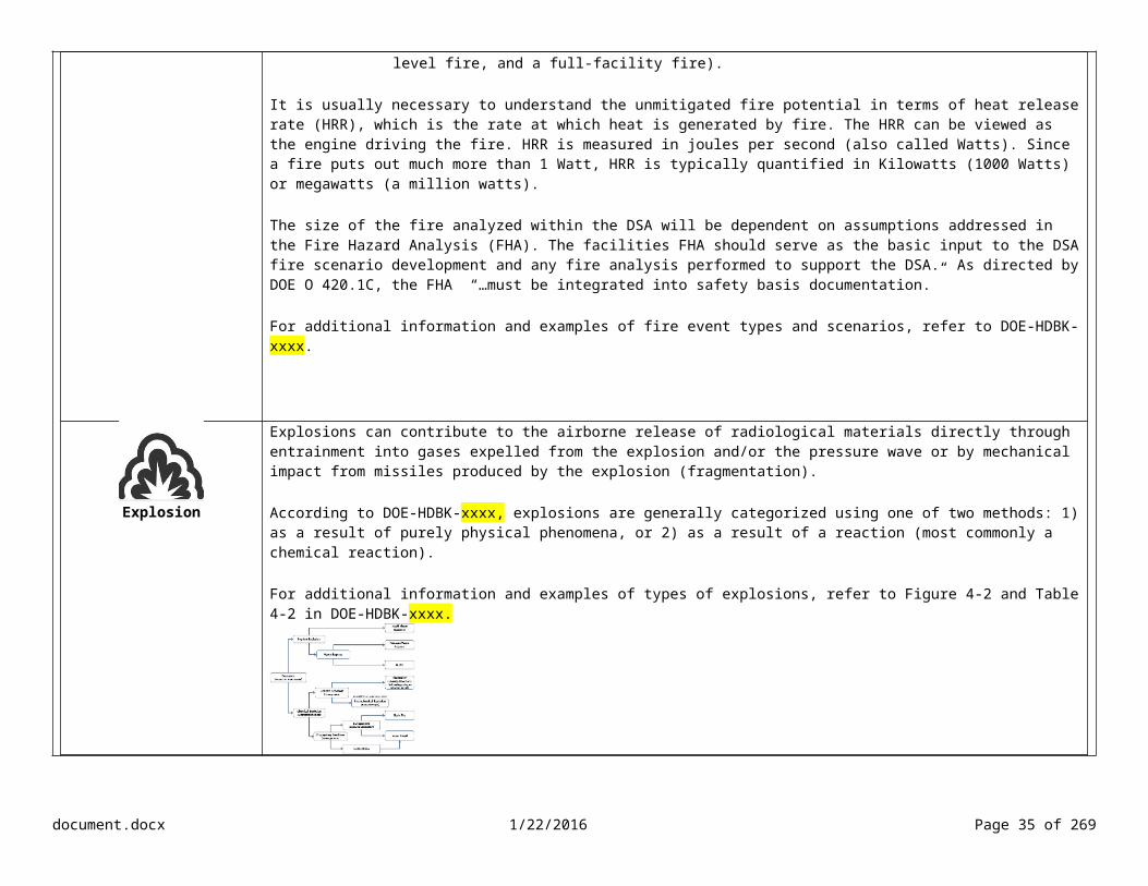
Explosion
Explosions can contribute to the airborne release of radiological materials directly through entrainment into gases expelled from the explosion and/or the pressure wave or by mechanical impact from missiles produced by the explosion (fragmentation).
According to DOE-HDBK-xxxx, explosions are generally categorized using one of two methods: 1) as a result of purely physical phenomena, or 2) as a result of a reaction (most commonly a chemical reaction).
For additional information and examples of types of explosions, refer to Figure 4-2 and Table 4-2 in DOE-HDBK-xxxx.
Loss of Containment/Confinement
Loss of containment/confinement, such as spills, can cause an airborne release of radiological material.
DOE-HDBK-xxxx defines spills as the accidental falling or flowing of material out of a confinement boundary. Spills can involve either a closed confinement system (e.g., sealed drum or tank) or an open confinement system (e.g., open container being handled in a glovebox).
When analyzing spills, it is important to identify the amount of material that is spilled and the mechanical mechanism involved. There are several types of insults that can result during a spill of material.
Puncture-Perforation Puncture-perforation of a container or confinement can release materials in a number of ways.
For the release of a volatile material, evaporation is the dominant mechanism. Some solids (e.g., phenol) may vaporize/sublime on release from perforated containers. Materials that are flammable gases or have combustible vapors can be vented and, in the
presence of an ignition source, result in secondary fires. Solutions with non-volatile solvents and powder may vent if the volume is pressurized. Free-fall spill/release of a solid may be followed by a period of evaporation or even
sublimation for volatile solids.
The release and free-fall of liquids and powders can result in suspension from shear stress at the air-material interface.
Crush-Impact This phenomenon imposes force on the surface of the material impacted and can fragment both solids (e.g., brittle fracture, displacement of powders) and liquids (e.g., splashing and droplet formation by displacement and shear).
Shock-Vibration If the surface is not fragmented, particles lying on the surface (e.g., surface contamination,
document.docx 1/22/2016 Page 29 of 204

corrosion products) can be jarred from the surface and suspended by vibratory/shock effects.
Abrasion This phenomenon consists of forces applied to the surface layer that induce fragmentation of the surface by mechanical action. Particles generated may be suspended by the mechanical action more efficiently than by aerodynamic forces.
For additional information on spills, refer to Section 4.4 in DOE-HDBK-xxxx.
Nuclear Criticality
The hazard of a criticality accident is unique to nuclear facilities and even then only to a subset of these facilities.
These nuclear facilities involve or will potentially involve radionuclides in such quantities that are equal to or greater than the single parameter limits for fissionable materials listed in ANSI/ANS-8.1-2014, Nuclear Criticality Safety in Operations with Fissionable Materials Outside Reactors, and ANSI/ANS-8.15-1981, Nuclear Criticality Control of Special Actinide Elements.
According to DOE-HDBK-xxxx, a criticality accident is the release of energy as a result of unintentionally producing a self-sustaining or divergent fission chain reaction.
Criticality accidents are primarily facility-worker safety concerns and would not be expected to ever expose the public or the environment to significant radiation doses, but could result in significant doses to co-located workers outside the nuclear facility.
According to DOE-HDBK-xxxx, criticality accidents have occurred almost exclusively in liquid (hydrogenous) media. The most common medium was fissile material in nitric acid, followed by an organic solution and then suspensions/slurries. The hydrogenous nature of the medium results in relatively slow fission excursions and insignificant likelihoods of mechanical (destructive) energy releases.
For additional information on nuclear criticality and accident analysis, refer to Appendix I in DOE-HDBK-xxxx.
External Events
Man-made external events can cause a breach in a confinement system or the structure of a facility.
The following external events are typically evaluated for DSA accident analysis: Aircraft crashes Vehicle crashes (e.g., vehicle crashing into facility and transportation accidents) Station blackout
For additional information on analyzing aircraft accidents, refer to DOE-STD-3014-2006, Accident Analysis for Aircraft Crash into Hazardous Facilities.
Natural Phenomena
Natural phenomena events can contribute to the airborne release of radioactive material through the mechanical forces breaching SSCs holding radioactive materials. In addition, natural phenomena events may cause a fire or explosion that could provide energy supporting the transport of radioactive material.
The natural phenomena of interest for most DOE sites include: seismic events (earthquakes) high winds (straight line, tornadoes, and hurricanes)
document.docx 1/22/2016 Page 30 of 204

floods heavy snow lightning volcanic activity wildland fires
For additional information on evaluating natural phenomena hazards, refer to DOE-HDBK-xxxx and DOE-HDBK-xxxx, Natural Phenomena Hazard Analysis and Design Handbook for DOE Facilities.
Chemical Reactions
Several specific chemical reactions are of interest in accident analysis due to their ability to contribute to the airborne release of radiological materials in nuclear materials processing and waste management as they can lead to loss of confinement, fire, and/or explosions.
Organic-Based Ion Exchange Resin Reaction
Synthetic ion exchange resins are commonly used in nuclear processing operations with plutonium nitrate solutions. Nitric acid is a powerful acid when concentrated and reacts violently with many organic compounds (such as turpentine, charcoal, and charred sawdust). The explosive properties of such reactions are aggravated by the production of gaseous reaction products, including steam, carbon dioxide, and nitrogen oxides.
Under conditions of rapid reaction between nitric acid and organic materials, the nitrogen oxides produced by the reaction are also reactive, and this further tends to accelerate the reaction. The result in a confined system can be rapid and accelerating pressurization, with the resulting hazard of bursting the ion exchange column or vessel. The nitrogen oxides themselves also represent a hazard to personnel.
Red Oil Reaction The PUREX solvent extraction process (and its variants) uses tri-n-butyl phosphate (TBP) and nitric acid as two principal components. These components, under certain extreme conditions of heating and nitric acid concentration, can react in an uncontrolled manner that could result in very serious consequences such as over-pressurization and rupture of a vessel, and fire or deflagration of flammable gases generated.
Incidents with TBP and nitric acid are often referred to as “Red Oil” incidents because of the red oily intermediates that form in the TBP phase in the course of the reaction.
There have been several reported incidents of damage in the nuclear industry as the result of high-temperature reactions between TBP and nitric acid or nitrates. The consequences from a TBP/nitric acid runaway reaction (“red oil explosion”) can vary significantly depending upon assumed initial conditions, vessel design, and other factors that influence the accident progression.
Organic Reaction Event
Nitrated organic compounds are in widespread use as propellants and explosives. The generation or accumulation of such materials in nuclear facilities may present a risk of runaway reaction, loss of confinement, or fire or explosion. The materials of primary potential concern include organic compounds containing nitrate or nitrite, but also may concern mixtures of organic material and nitric acid. These materials may be solids, liquids, gels, or slurries.
This type of event is of particular concern in waste materials. Such materials may include spent resins, degraded solvents, analytical reagents, and lubricants that have been exposed to acid.
document.docx 1/22/2016 Page 31 of 204
In general, reaction of unstable chemical systems will be initiated or accelerated by heating.Hydroxylamine Nitrate Reaction
Hydroxylamine (NH2OH) is used in the nuclear industry as a reducing agent and in decontaminating solutions. It is used as the nitrate (HAN) or sulfate (HAS) salt in solution. It has the advantage of reducing plutonium smoothly to the trivalent state without creating potential solid waste.
Hydroxylamine is unstable against decomposition in the presence of nitric acid, and this reaction is catalyzed by dissolved iron. This reaction occurs more readily at higher nitric acid concentrations. It appears that the formation of nitrous acid is an important element in the mechanism. This reaction, once begun, can accelerate to a dangerous rate, producing great quantities of gas and pressurizing containers.
For additional information on chemical reactions, refer to Section 4.5 of DOE-HDBK-xxxx.
Narration<Bob> During the hazard evaluation, you identified the event type for each hazard scenario. Now we need to examine the details about each. Programming InstructionsAdd icons for Table 4-2 and Figure 4-2 from AA Handbook. Show enlarged view when user selects icons.When user selects trivalent, show definition: “Valence refers to the oxidation state of an atom present in a compound. A compound with an oxidation state of +3 is referred to as trivalent.” Media Instructionssba130_01_02_05.mp3
document.docx 1/22/2016 Page 32 of 204

Lesson/Objective Select design basis accidents (DBAs)/evaluation basis accidents (EBAs) for an accident analysis. Slide #Slide Content Screen Type
Grouping Accidents by Event Type – Operational AccidentsSelect each event type to view the scenarios.
Nuclear Criticality
ID # Type Scenario Initiating Event or Cause
NC-01 Operational Accident/Nuclear Criticiality
Improper stacking of high fissile gram equivalent drums cause inadvertent criticality
Waste containers with significant fissionable material are stacked in a configuration that causes a criticality
NC-02 Operational Accident/Nuclear Criticality
Room fire suppression water enters glovebox and water accumulates in the bottom with presence of fissile material
Activation of fire suppression system and pathway created that allows water to enter glovebox
Loss of Containment
ID # Type Scenario Initiating Event or Cause
CC-01 Operational Accident/Loss of Containment/Confinement
Forklift tine punctures TRU waste container
Forklift impacts TRU waste container during handling
CC-02 Cylinder impacts TRU waste container Damaged cylinder impacts TRU waste container during handling
CC-03 Reaction products, flammable gas build-up, expansion of container contents
Waste container vent failure causes gas build-up in staging area
CC-04 Container containing Pu238 dropped outside of glovebox
Degraded container, mechanical impact, or dropped during handling
CC-05 Container inside glovebox dropped, contents spill onto glovebox floor
Degraded container, mechanical impact, or dropped during handling
CC-06 Sample leaks from dropped container being transferred outside glovebox
Dropped container
CC-07 Improper securing of equipment in glovebox; during operation equipment impacts glovebox window and glovebox breach occurs
Equipment not properly secured
CC-08 TRU waste container strikes floor and spills contents
Drum falls from lifting device
CC-09 Furnace operations result in overpressure of container, projectile breaks glovebox window
Operator error and equipment failure
CC-10 Lid on dissolution vessel fails to seal; solution boils off, and glovebox/gloves breached by acid attack
Lid improperly sealed
ID # Type Scenario Initiating Event or Cause
F-01 Operational Accident/Fire
Forklift accident in TRU waste staging area
Forklift fuel tank damage, fuel leaks, causes a fire, and spreads to drums
document.docx 1/22/2016 Page 33 of 204

Fire F-02 Any ignition source (e.g., power tools, hotwork) ignites combustibles in the glovebox
Fire consumes rubber gloves or breaches HEPA filters or ductwork, causing loss of confinement (potential for direct release path to exterior of building)
F-03 Drum connected to glovebox, contents ignite, spreading fire to combustibles, impacting the glovebox confinement
Pyrophoric, flammable (including combustible) liquid, gas, or oxidizer material ignites, or spontaneous combustion causes fire
F-04 Furnace temperature excursion, combustibles adjacent to furnace, fire inside glovebox, and glovebox breach
Furnace malfunction
F-05 Room fire ignites combustibles, spreads to glovebox, and glovebox breach
Electrical short
F-06 Pyrophoric Pu ignites combustibles in glovebox resuling in fire inside glovebox
Glovebox inerting system malfunction
F-07 Room fire spreads, engulfs shielding on sides of Pu238 glovebox, resulting in dispersal of Pu238 oxide
Ignition of transient combustibles such as plastic bags
F-08 Drum contents ignite combustibles nearby and fire spreads in waste staging area
Pyrophoric flammable (including combustible) liquid, gas, or oxidizer material in drums ignite, or spontaneous combustion causes fire
F-09 Pu metal fire in glovebox (impure metal or metal contained in a pyrochemical residue is being oxided in a furnace before aqueous recovery)
Furnace controller malfunctions while an excess of oxygen is added, Pu becomes molten and oxidizes voilently
F-10 Fire in glovebox conducting aqueous chloride plutonium recovery operations (liquid fire)
Electrical short in equipment ignites combustibles in glovebox which in turn heat and ignite the organic extraction liquid
Explosions/Deflagrations
ID # Type Scenario Initiating Event or Cause
ED-01 Operational Accident/Explosion
Built-up gas released while opening TRU waste container results in deflagration impacting the waste and glovebox
Flammable gas build-up in TRU waste container
ED-02 Operational Accident/Explosion
Deflagration of flammable gases in TRU waste containers during handling in the vehicle airlock
Forklift impact with TRU waste container initiates deflagration and/or fire
ED-03 Operational Accident/Explosion
Explosion breaches waste containers in staging area
Vehicle accident involving full loaded propane cylinder delivery truck
Direct Exposure
ID # Type Scenario Initiating Event or Cause
DE-01 Operational Accident/Direct Exposure
Worker exposed to penetrating radiation Unexpected radioactive source is removed from waste containers attached to glovebox
document.docx 1/22/2016 Page 34 of 204
DE-02 Operational Accident/Direct Exposure
Worker exposed to radiation Radioactive source falls from shield waste drum
Chemical Reaction
ID # Type Scenario Initiating Event or Cause
CR-01 Operational Accident/Chemical Reaction
Chemical exothermic reaction leads to fire Corrosion reaction and exposure to strong acids/bases in 55-gal waste drum
CR-02 Operational Accident/Chemical Reaction
During movement of drums, chemical exothermic reaction leads to overpressurization and venting
Chemical exothermic reaction in 55-gal waste drum
CR-03 Operational Acciden/tChemical Reaction
During transfer of drums, drum lid fails Corrosive materials causes failure of drum containment/integrity
Narration<Bob> Now that we’ve reviewed the event types, we need to group the accidents by type. Let’s start with the operational accidents. As you can see, we have event types for nuclear criticality, loss of containment, fire, explosion, direct exposure, and chemical reaction.Programming Instructions
Media Instructionssba130_01_02_06.mp3
document.docx 1/22/2016 Page 35 of 204

Lesson/Objective Select design basis accidents (DBAs)/evaluation basis accidents (EBAs) for an accident analysis. Slide #Slide Content Screen Type
Grouping Accidents by Event Type – Man-Made External EventsReview the man-made external events.
ID # Type Scenario Initiating Event or Cause
EE-01 External Event/Fire Fire spreads impacting TRU waste containers staged outside
Vehicle (not facility related) or refueling truck accident adjacent to site causes fuel leak
EE-02 External Event/Aircraft Crash Aircraft crash Aircraft crashes into staging area or building causing a full facility (inside and outside) fire
EE-03 External Event/Explosion Explosion breaches waste containers and contents burn
Vehicle accident results in fuel leak and fuel tank explosion
EE-04 Exernal Event/Station Blackout
Loss of AC power results in loss of ventilation (direct current power is not assumed availble)
Equipment malfunction or natural event
Narration<Bob> We also need to group the accidents for man-made externals event such as aircraft crash, vehicle or transportation accidents, and station blackouts. Programming Instructions
Media Instructionssba130_01_02_07.mp3
document.docx 1/22/2016 Page 36 of 204

Lesson/Objective Select design basis accidents (DBAs)/evaluation basis accidents (EBAs) for an accident analysis. Slide #Slide Content Screen Type
Grouping Accidents by Event Type – Natural PhenomenaID # Event Type Scenario Initiating Event or Cause
NPH-01 Natural Phenomena/Wildfire Grass/brush fire in fields impacts TRU waste containers staged outside (potential for fire to spread to the building)
Wildfire adjacent to site
NPH-02 Natural Phenomena/Lightning Ignition of combustibles impacts TRU waste containers staged outside (potential for fire to spread to the building)
Lightning causes fire in yard and/or container
NPH-02 Natural Phenomena/Lightning Fire spreads through building and impacts glovebox Lightning initiates fire inside the buildingNPH-03 Natural Phenomena/Seismic Event Fire and structural debris impact glovebox Seismic event initiates electrical fire inside building and
fire spreads outsideNPH-04 Natural Phenomena/Seismic Event Structural damage to building, debris impacts TRU waste
containersSeismic event
NPH-05 Natural Phenomena/High Wind Structural damage to building and debris breach TRU waste containers
High wind
Narration<Bob> As you can see, we also have natural phenomena hazards for a wildfire, lightning, seismic event, and high wind. According to DOE-STD-3009, we need to consider the cumulative effects of releases from NPH-induced structural and equipment failures, such as the impacts, spills, fires, and explosions caused by NPH.Programming Instructions
Media Instructionssba130_01_02_08.mp3
document.docx 1/22/2016 Page 37 of 204

Lesson/Objective Select design basis accidents (DBAs)/evaluation basis accidents (EBAs) for an accident analysis. Slide #Slide Content Screen Type
Grouping Accidents by Event Type Knowledge CheckDrag and drop the event type to the accident scenario.
Scenario Initiating Event or Cause
Burning combustible/flammable material in staging area
Electrical failure of wiring ignites fire
FireDuring crane operations, drop of container causes breach
Crane mechanical failure causes drop of container
Loss of ContainmentPropane fueled forklift leaks fuel and fuel/air mixture explodes
Propane fueled forklift leaks fuel
ExplosionContainers drop from shelves onto other stored material, breaching containers
Vault shelving fails
Loss of Containment Narration<Bob> Before we continue, let’s make sure you can group accidents by the event type. Programming InstructionsTry again. Incorrect. <Show visual feedback> The correct answers are shown above. Correct.Media Instructionssba130_01_02_09.mp3
document.docx 1/22/2016 Page 38 of 204

Lesson/Objective Select design basis accidents (DBAs)/evaluation basis accidents (EBAs) for an accident analysis. Slide #Slide Content Screen Type
Fires – Grouping by Accident Environment Conditions
MAR type and quantity involved in the accident
Accident initiators such as ignition sources and equipment malfunctions
Configuration of the fire area
Accident progression Narration<Bob> Now we need to examine each scenario and group those with similar accident environment conditions. When grouping scenarios by accident environment conditions, you should consider the MAR type and quantity involved in the accident, the accident initiators such as ignition sources and equipment malfunctions, the configuration of the fire area, and the accident progression.
Also, remember that DOE-HDBK-xxxx identified four types of fires: fuel pool fires, small fires, enclosure fires, and large fires. Keep these types of fires in mind when grouping by accident environment conditions.Feedback Instructions
Programming Instructionssba130_01_02_10.mp3
document.docx 1/22/2016 Page 39 of 204

Lesson/Objective Select design basis accidents (DBAs)/evaluation basis accidents (EBAs) for an accident analysis. Slide #Slide Content Screen Type
Grouping by Accident Environment Conditions – Fire in the Staging AreaSelect the scenarios that result in fires in the staging area.
ID # Type Scenario Initiating Event or Cause
F-01 Operational Accident/Fire
Forklift accident in TRU waste staging area Forklift fuel tank damage, fuel leaks, causes a fire, and spreads to drums F-02 Any ignition source (e.g., power tools,
hotwork) ignites combustibles in the glovebox
Fire consumes rubber gloves or breaches HEPA filters or ductwork, causing loss of confinement (potential for direct release path to exterior of building)
F-03 Drum connected to glovebox, contents ignite, spreading fire to combustibles, impacting the glovebox confinement
Pyrophoric, flammable (including combustible) liquid, gas, or oxidizer material ignites, or spontaneous combustion causes fire
F-04 Furnace temperature excursion, combustibles adjacent to furnace, fire inside glovebox, and glovebox breach
Furnace malfunction
F-05 Room fire ignites combustibles, spreads to glovebox, and glovebox breach
Electrical short
F-06Pyrophoric Pu ignites combustibles in glovebox resuling in fire inside glovebox
Glovebox inerting system malfunction
F-07 Room fire spreads, engulfs shielding on sides of Pu238 glovebox, resulting in dispersal of Pu238 oxide
Ignition of transient combustibles such as plastic bags
F-08 Drum contents ignite combustibles nearby and fire spreads in waste staging area
Pyrophoric flammable (including combustible) liquid, gas, or oxidizer material in drums ignite, or spontaneous combustion causes fire
F-09 Pu metal fire in glovebox (impure metal or
metal contained in a pyrochemical residue is being oxided in a furnace before aqueous recovery)
Furnace controller malfunctions while an excess of oxygen is added, Pu becomes molten and oxidizes voilently
F-10 Fire in glovebox conducting aqueous chloride plutonium recovery operations (liquid fire)
Electrical short in equipment ignites combustibles in glovebox which in turn heat and ignite the organic extraction liquid
Narration<Bob> These scenarios are all operational accidents resulting in fire. However, some of the scenarios occur in the glovebox, outside of the glovebox, or in the staging area. Why don’t you start by identifying the fires in the staging area?Feedback InstructionsImmediate visual feedback (turn green/green check)Programming Instructionssba130_01_02_11.mp3
document.docx 1/22/2016 Page 40 of 204

Lesson/Objective Select design basis accidents (DBAs)/evaluation basis accidents (EBAs) for an accident analysis. Slide #Slide Content Screen Type
Grouping by Accident Environment Conditions – Fire Inside the Glovebox Knowledge CheckSelect the fire scenarios that are initiated inside the glovebox.
ID # Type Scenario Initiating Event or Cause
F-01 Operational Accident/Fire
Forklift accident in TRU waste staging area Forklift fuel tank damage, fuel leaks, causes a fire, and spreads to drums Staging Area
F-02 Any ignition source (e.g., power tools, hotwork) ignites combustibles in the glovebox
Fire consumes rubber gloves or breaches HEPA filters or ductwork, causing loss of confinement (potential for direct release path to exterior of building)
F-03 Drum connected to glovebox, contents ignite, spreading fire to combustibles, impacting the glovebox confinement
Pyrophoric, flammable (including combustible) liquid, gas, or oxidizer material ignites, or spontaneous combustion causes fire
F-04 Furnace temperature excursion, combustibles adjacent to furnace, fire inside glovebox, and glovebox breach
Furnace malfunction
F-05 Room fire ignites combustibles, spreads to glovebox, and glovebox breach
Electrical short
F-06Pyrophoric Pu ignites combustibles in glovebox resuling in fire inside glovebox
Glovebox inerting system malfunction F-07 Room fire spreads, engulfs shielding on
sides of Pu238 glovebox, resulting in dispersal of Pu238 oxide
Ignition of transient combustibles such as plastic bags
F-08 Drum contents ignite combustibles nearby and fire spreads in waste staging area
Pyrophoric flammable (including combustible) liquid, gas, or oxidizer material in drums ignite, or spontaneous combustion causes fire
Staging Area
F-09 Pu metal fire in glovebox (impure metal or metal contained in a pyrochemical residue is being oxided in a furnace before aqueous recovery)
Furnace controller malfunctions while an excess of oxygen is added, Pu becomes molten and oxidizes voilently
F-10 Fire in glovebox conducting aqueous chloride plutonium recovery operations (liquid fire)
Electrical short in equipment ignites combustibles in glovebox which in turn heat and ignite the organic extraction liquid
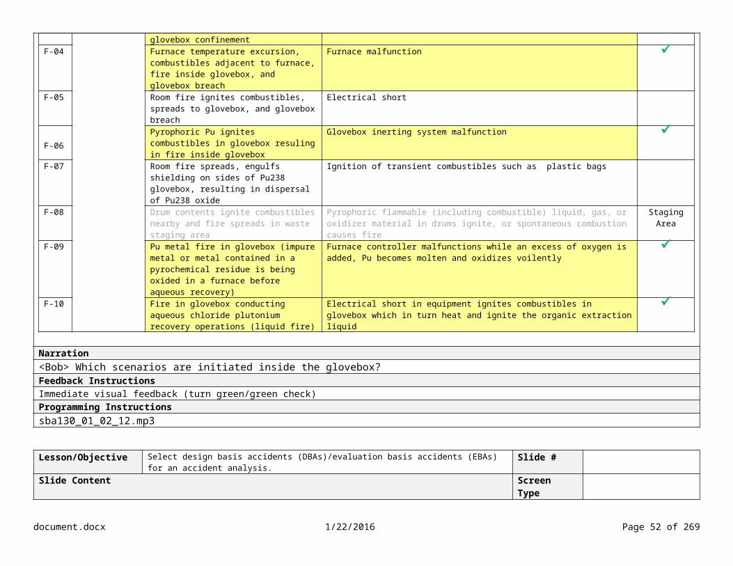
Narration<Bob> Which scenarios are initiated inside the glovebox?Feedback InstructionsImmediate visual feedback (turn green/green check)Programming Instructionssba130_01_02_12.mp3
document.docx 1/22/2016 Page 41 of 204

Lesson/Objective Select design basis accidents (DBAs)/evaluation basis accidents (EBAs) for an accident analysis. Slide #Slide Content Screen Type
Grouping by Accident Environment Conditions – Fire Outside the Glovebox
ID # Type Scenario Initiating Event or Cause
F-01 Operational Accident/Fire
Forklift accident in TRU waste staging area
Forklift fuel tank damage, fuel leaks, causes a fire, and spreads to drums Staging Area
F-02 Any ignition source (e.g., power tools, hotwork) ignites combustibles in the glovebox
Fire consumes rubber gloves or breaches HEPA filters or ductwork, causing loss of confinement (potential for direct release path to exterior of building)
Inside the Glovebox
F-03 Drum connected to glovebox, contents ignite, spreading fire to combustibles, impacting the glovebox confinement
Pyrophoric, flammable (including combustible) liquid, gas, or oxidizer material ignites, or spontaneous combustion causes fire
Inside the Glovebox
F-04 Furnace temperature excursion, combustibles adjacent to furnace, fire inside glovebox, and glovebox breach
Furnace malfunction Inside the Glovebox
F-05 Room fire ignites combustibles, spreads to glovebox, and glovebox breach
Electrical short Outside of the
Glovebox
F-06Pyrophoric Pu ignites combustibles in glovebox resuling in fire inside glovebox
Glovebox inerting system malfunction Inside the Glovebox
F-07 Room fire spreads, engulfs shielding on sides of Pu238 glovebox, resulting in dispersal of Pu238 oxide
Ignition of transient combustibles such as plastic bags Outside of the
GloveboxF-08 Drum contents ignite combustibles
nearby and fire spreads in waste staging area
Pyrophoric flammable (including combustible) liquid, gas, or oxidizer material in drums ignite, or spontaneous combustion causes fire
Staging Area
F-09 Pu metal fire in glovebox (impure metal or metal contained in a pyrochemical residue is being oxided in a furnace before aqueous recovery)
Furnace controller malfunctions while an excess of oxygen is added, Pu becomes molten and oxidizes voilently
Inside the Glovebox
F-10 Fire in glovebox conducting aqueous chloride plutonium recovery operations (liquid fire)
Electrical short in equipment ignites combustibles in glovebox which in turn heat and ignite the organic extraction liquid
Inside the Glovebox
Narration<Bob> The remaining fires are initiated outside of the glovebox. Feedback Instructions
Programming Instructionssba130_01_02_13.mp3
document.docx 1/22/2016 Page 42 of 204

Lesson/Objective Select design basis accidents (DBAs)/evaluation basis accidents (EBAs) for an accident analysis. Slide #Slide Content Screen Type
Grouping by Accident Environment Conditions – Fire Scenario Summary
ID # Type Scenario Initiating Event or Cause
F-01 Operational Accident/Fire
Forklift accident in TRU waste staging area
Forklift fuel tank damage, fuel leaks, causes a fire, and spreads to drums Staging Area
F-02 Any ignition source (e.g., power tools, hotwork) ignites combustibles in the glovebox
Fire consumes rubber gloves or breaches HEPA filters or ductwork, causing loss of confinement (potential for direct release path to exterior of building)
Inside the Glovebox
F-03 Drum connected to glovebox, contents ignite, spreading fire to combustibles, impacting the glovebox confinement
Pyrophoric, flammable (including combustible) liquid, gas, or oxidizer material ignites, or spontaneous combustion causes fire
Inside the Glovebox
F-04 Furnace temperature excursion, combustibles adjacent to furnace, fire inside glovebox, and glovebox breach
Furnace malfunction Inside the Glovebox
F-05 Room fire ignites combustibles, spreads to glovebox, and glovebox breach
Electrical short Outside the Glovebox
F-06Pyrophoric Pu ignites combustibles in glovebox resuling in fire inside glovebox
Glovebox inerting system malfunction Inside the Glovebox
F-07 Room fire spreads, engulfs shielding on sides of Pu238 glovebox, resulting in dispersal of Pu238 oxide
Ignition of transient combustibles such as plastic bags Outside the Glovebox
F-08 Drum contents ignite combustibles nearby and fire spreads in waste staging area
Pyrophoric flammable (including combustible) liquid, gas, or oxidizer material in drums ignite, or spontaneous combustion causes fire
Staging Area
F-09 Pu metal fire in glovebox (impure metal or metal contained in a pyrochemical residue is being oxided in a furnace before aqueous recovery)
Furnace controller malfunctions while an excess of oxygen is added, Pu becomes molten and oxidizes voilently
Inside the Glovebox
F-10 Fire in glovebox conducting aqueous chloride plutonium recovery operations (liquid fire)
Electrical short in equipment ignites combustibles in glovebox which in turn heat and ignite the organic extraction liquid
Inside the Glovebox
Narration<Bob> Based on our selections, we have three groups of fire scenarios based on the accident environment conditions: fires initiated in the staging area, inside the glovebox, and outside of the glovebox. Remember that when grouping scenarios by accident environment conditions, you should also consider the MAR type and quantity involved in the accident, the accident initiators such as ignition sources and equipment malfunctions, the configuration of the fire area, and the accident progression. Feedback Instructions
Programming InstructionsShow each group with insync with narrationsba130_01_02_14.mp3
document.docx 1/22/2016 Page 43 of 204

document.docx 1/22/2016 Page 44 of 204

Lesson/Objective Select design basis accidents (DBAs)/evaluation basis accidents (EBAs) for an accident analysis. Slide #Slide Content Screen Type
Grouping by Accident Environment Conditions – Loss of Confinement/Spills Knowledge Check
Select the spill scenarios that are initiated by an external energy source such as puncturing, crushing, or dropping outside the glovebox.
ID # Type Scenario Initiating Event or Cause
CC-01 Operational Accident/Loss of Containment/Confinement
Forklift tine punctures TRU waste container Forklift impacts TRU waste container during handling in staging area
CC-02 Cylinder impacts TRU waste container Damaged cylinder impacts TRU waste container during
handling in staging area
CC-03 Reaction products, flammable gas build-up, expansion of container contents
Waste container vent failure causes gas build-up in staging area
CC-04 Container containing Pu238 dropped outside of glovebox
Degraded container, mechanical impact, or dropped during handling
CC-05 Container inside glovebox dropped, contents spill onto
glovebox floorDegraded container, mechanical impact, or dropped during handling
CC-06 Sample leaks from dropped container being transferred outside glovebox
Dropped container CC-07 Improper securing of equipment/tools in glovebox;
during operation equipment impacts glovebox window and glovebox breach occurs
Equipment/tools not properly secured
CC-08 TRU waste container strikes floor and spills contents Drum falls from lifting device CC-09 Furnace operations in glovebox result in overpressure
of container, projectile breaks glovebox windowOperator error and equipment failure
CC-10 Lid on dissolution vessel fails to seal; solution boils off, and glovebox/gloves breached by acid attack
Lid improperly sealed
Narration<Bob> Now we need to repeat the process of grouping by accident environment conditions for the remaining accidents and event types. Let’s examine the accident scenarios for loss of confinement and spills. Remember that spills can be defined as the accidental falling or flowing of material out of a confinement boundary. You should also consider the MAR type and quantity, the accident initiator, and configuration of the confinement boundary. Which spill scenarios are initiated by an external energy source such as puncturing, crushing, or dropping outside the glovebox? Feedback InstructionsImmediate visual feedbackMedia Instructionssba130_01_02_15.mp3
document.docx 1/22/2016 Page 45 of 204

Lesson/Objective Select design basis accidents (DBAs)/evaluation basis accidents (EBAs) for an accident analysis. Slide #Slide Content Screen Type
Grouping by Accident Environment Conditions – Loss of Confinement/Spills from Over-Pressurization or Chemical Reaction
HA-ID
# Type Scenario Initiating Event or Cause
CC-01 Operational Accident/Loss of Containment/Confinement
Forklift tine punctures TRU waste container Forklift impacts TRU waste container during handling in staging area Outside of GloveboxCC-02 Cylinder impacts TRU waste container Damaged cylinder impacts TRU waste container during handling in staging
areaOutside of Glovebox
CC-03 Reaction products, flammable gas build-up, expansion of container contents
Waste container vent failure causes gas build-up in staging area CC-04 Container containing Pu238 dropped
outside of gloveboxDegraded container, mechanical impact, or dropped during handling Outside of Glovebox
CC-05 Container inside glovebox dropped, contents spill onto glovebox floor
Degraded container, mechanical impact, or dropped during handling
CC-06 Sample leaks from dropped container being transferred outside glovebox
Dropped container Outside of Glovebox
CC-07 Improper securing of equipment/tools in glovebox; during operation equipment impacts glovebox window and glovebox breach occurs
Equipment/tools not properly secured
CC-08 TRU waste container strikes floor and spills contents
Drum falls from lifting device Outside of Glovebox
CC-09 Furnace operations in glovebox result in overpressure of container, projectile breaks glovebox window
Operator error and equipment failure
CC-10 Lid on dissolution vessel fails to seal; solution boils off, and glovebox/gloves breached by acid attack
Lid improperly sealed
Narration<Bob> These spill scenarios involve over-pressurizations and/or chemical reactions. We’ll keep these as a separate group. Feedback Instructions
Media Instructionssba130_01_02_16.mp3
document.docx 1/22/2016 Page 46 of 204

Lesson/Objective Select design basis accidents (DBAs)/evaluation basis accidents (EBAs) for an accident analysis. Slide #Slide Content Screen Type
Grouping by Accident Environment Conditions – Loss of Confinement/Spills Inside the Glovebox
HA-ID #
Type Scenario Initiating Event or Cause
CC-01 Operational Accident/Loss of Containment/Confinement
Forklift tine punctures TRU waste container Forklift impacts TRU waste container during handling in staging area
Outside the Glovebox
CC-02 Cylinder impacts TRU waste container Damaged cylinder impacts TRU waste container during handling in staging area
Outside the Glovebox
CC-03 Reaction products, flammable gas build-up, expansion of container contents
Waste container vent failure causes gas build-up in staging area Over-pressurization or Chemical Reaction
CC-04 Container containing Pu238 dropped outside of glovebox
Degraded container, mechanical impact, or dropped during handling
Outside the Glovebox
CC-05 Container inside glovebox dropped, contents spill onto glovebox floor
Degraded container, mechanical impact, or dropped during handling
Inside the Glovebox
CC-06 Sample leaks from dropped container being transferred outside glovebox
Dropped container Outside the Glovebox
CC-07 Improper securing of equipment/tools in glovebox; during operation equipment impacts glovebox window and glovebox breach occurs
Equipment/tools not properly secured Inside the Glovebox
CC-08 TRU waste container strikes floor and spills contents Drum falls from lifting device Outside the Glovebox
CC-09 Furnace operations in glovebox result in overpressure of container, projectile breaks glovebox window
Operator error and equipment failure Over-pressurization or Chemical Reaction
CC-10 Lid on dissolution vessel fails to seal; solution boils off, and glovebox/gloves breached by acid attack
Lid improperly sealed Over-pressurization or Chemical Reaction
Narration<Bob> The remaining scenarios are initiated inside the glovebox. Feedback Instructions Media Instructionssba130_01_02_17.mp3
document.docx 1/22/2016 Page 47 of 204

Lesson/Objective Select design basis accidents (DBAs)/evaluation basis accidents (EBAs) for an accident analysis. Slide #Slide Content Screen Type
Grouping by Accident Environment Conditions – Loss of Confinement/Spills SummaryHA-ID # Type Scenario Initiating Event or Cause
CC-01 Operational Accident/Loss of Containment/Confinement
Forklift tine punctures TRU waste container Forklift impacts TRU waste container during handling in staging area
Outside of Glovebox
CC-02 Cylinder impacts TRU waste container Damaged cylinder impacts TRU waste container during handling in staging area
Outside of Glovebox
CC-03 Reaction products, flammable gas build-up, expansion of container contents
Waste container vent failure causes gas build-up in staging area
Over-pressurization or Chemical Reaction
CC-04 Container containing Pu238 dropped outside of glovebox
Degraded container, mechanical impact, or dropped during handling
Outside of Glovebox
CC-05 Container inside glovebox dropped, contents spill onto glovebox floor
Degraded container, mechanical impact, or dropped during handling
Inside of Glovebox
CC-06 Sample leaks from dropped container being transferred outside glovebox
Dropped container Outside of Glovebox
CC-07 Improper securing of equipment/tools in glovebox; during operation equipment impacts glovebox window and glovebox breach occurs
Equipment/tools not properly secured Inside of Glovebox
CC-08 TRU waste container strikes floor and spills contents Drum falls from lifting device Outside of GloveboxCC-09 Furnace operations in glovebox result in overpressure
of container, projectile breaks glovebox windowOperator error and equipment failure Over-pressurization or
Chemical ReactionCC-10 Lid on dissolution vessel fails to seal; solution boils off,
and glovebox/gloves breached by acid attackLid improperly sealed Over-pressurization or
Chemical Reaction Narration<Bob> We now have three groupings of loss of confinement/spill scenarios based on accident environment conditions: 1) scenarios involving over-pressurizations and/or chemical reactions, 2) scenarios initiated outside of the glovebox, and 3) scenarios initiated inside the glovebox. Programming InstructionsShow groups in sync with narrationMedia Instructionssba130_01_02_18.mp3
document.docx 1/22/2016 Page 48 of 204

Lesson/Objective Select design basis accidents (DBAs)/evaluation basis accidents (EBAs) for an accident analysis. Slide #Slide Content Screen Type
Key Points
Categorize by accident type (e.g., operational accident, natural phenomena event, and man-made external event)
Group accidents by event type (e.g., fire, explosion, loss of containment/confinement)
Consider accident environment conditions MAR type and quantity involved in the accident Accident initiators such as ignition sources and equipment malfunctions Configuration of the room, area, or confinement boundary Accident progression
Narration
Programming Instructions
Media Instructions
document.docx 1/22/2016 Page 49 of 204

Lesson/Objective NA Slide #Slide Content Screen Type
Selecting DBAs/EBAs ProcessSelect each step to learn more.
Narration
Programming Instructions
Media Instructions
document.docx 1/22/2016 Page 50 of 204

Lesson/Objective Select design basis accidents (DBAs)/evaluation basis accidents (EBAs) for an accident analysis. Slide #Slide Content Screen Type
Selecting Representative Bounding AccidentsFire Scenario Accident Initiator
1 Initiated inside glovebox (enclosure fire)
F-02 – Ignition source (power tools, hotwork) F-03 – Pyrophoric, flammable (including combustibles) liquid, gas, or oxidizer material ignitesF-04 – Furnace temperature excursionF-06 – Pyrophoric material ignitesF-09 – Furnace controller malfunctions with Pu metal in gloveboxF-10 – Electrical short (in glovebox)
2 Initiated outside glovebox (potential for small fire progression to large fire)
F-05 – Electrical shortF-07 – Ignition of transient combustibles such as plastic bags
3 Initiated in waste staging area (potential pool fire)
F-01 – Forklift fuel tank damage, fuel leaksF-08 – Drum contents ignite combustibles
Narration<Bob> Remember that DOE-HDBK-xxxx identified four types of fires: enclosure fires, small fires, large fires, and fuel pool fires. From our scenarios, we identified groups for enclosure fires, small fires with the potential to progress to large fires, and pool fires.
Now that we’ve grouped the fire scenarios based on similar accident environment conditions, the next step is to select the representative bounding accidents. For this step, we need to determine which scenario has the highest unmitigated consequences for both the public and the co-located worker within each group. We also need to ensure that the representative accident we select has similar controls to the other accidents in that group. The accidents we select are referred to as representative bounding accidents. Per Section 3.2.1 of DOE-STD-3009, the contractor must select at least one bounding accident from each of the major types that has the potential to challenge the EG.Programming Instructions
Media Instructionssba130_01_02_19.mp3
document.docx 1/22/2016 Page 51 of 204
Lesson/Objective Select design basis accidents (DBAs)/evaluation basis accidents (EBAs) for an accident analysis. Slide #Slide Content Screen Type
Selecting Representative Bounding Accidents – Fire in Staging Area Knowledge CheckSelect the scenario with the highest unmitigated consequences for the public and co-located worker, as well as similar bounding controls.
ID # Type Scenario Initiating Event or Cause
Description Likelihood Consequence Risk NotesP CW W P CW W
F-01 Operational Accident/Fire
Forklift accident in TRU waste staging area
Forklift fuel tank damage, fuel leaks, causes a fire, and spreads to drums
Uncontrolled U H H H I I I
Controlled EU M M M III III IIIBuilding confinement ventilation system
Building structural integrity
Combustible loading program
Emergency Preparedness Program
Fire Protection ProgramBuilding and glovebox fire suppression system
Vehicle fuel restrictions TRU waste container design integrity
Maintenance programF-08 Operational
Accident/FireDrum contents ignite combustibles nearby and fire spreads in waste staging area
Pyrophoric flammable (including combustible) liquid, gas, or oxidizer material in drums ignite, or spontaneous combustion causes fire
Uncontrolled EU M M M III III III
Controlled BEU L L L IV IV IVBuilding confinement ventilation system
Building structural integrity
Combustible loading program
Emergency Preparedness Program
document.docx 1/22/2016 Page 52 of 204

Fire Protection ProgramBuilding and glovebox fire suppression system
TRU waste container design integrity
Narration<Bob> We need to select the representative bounding accident for this group. Examine the credited controls identified during the hazard evaluation, as well as the unmitigated consequences for the public and co-located worker. Which accident scenario has the highest unmitigated consequences for the public and co-located worker, and also has credited controls that bound the other accidents? Programming InstructionsWhen learner selects scenario, expand to show the related controls.Try again. Which scenario has controls that bound the other scenario? Incorrect. <Show visual feedback>This scenario has moderate unmitigated consequences to the public and co-located worker. That’s correct. Media Instructionssba130_01_02_20.mp3
document.docx 1/22/2016 Page 53 of 204

Lesson/Objective Select design basis accidents (DBAs)/evaluation basis accidents (EBAs) for an accident analysis.
Slide #
Slide Content Screen Type
Selecting Representative Bounding Accidents – Fire Inside the Glovebox
ID # Type Scenario Initiating Event or Cause
Description Likelihood Consequence Risk NotesP CW W P CW W
F-02 Operational Accident/Fire
Any ignition source (e.g., power tools, hotwork) ignites combustibles in the glovebox
Fire consumes rubber gloves or breaches HEPA filters or ductwork, causing loss of confinement (potential for direct release path to exterior of building)
Uncontrolled U M M H II II I
Controlled EU L L M IV IV IIIBuilding confinement ventilation system
Building structural integrity
Combustible loading program
Emergency Preparedness Program
Building and glovebox fire suppression system
Glovebox design integrity and confinement
F-03 Operational Accident/Fire
Drum connected to glovebox, contents ignite, spreading fire to combustibles, impacting the glovebox confinement
Pyrophoric, flammable (including combustible) liquid, gas, or oxidizer material ignites, or spontaneous combustion causes fire
Uncontrolled U H H H I I I
Controlled EU L L M IV IV IIIBuilding confinement ventilation system
Building structural integrity
Combustible loading program
Emergency Preparedness Program
Building and glovebox fire suppression system
Glovebox design integrity and confinement
document.docx 1/22/2016 Page 54 of 204

High-temp limiting switch
F-04 Operational Accident/Fire
Furnace temperature excursion, combustibles adjacent to furnace, fire inside glovebox, and glovebox breach
Furnace malfunction Uncontrolled U H H H I I I
Controlled EU L L M IV IV IIIBuilding confinement ventilation system
Building structural integrity
Combustible loading program
Emergency Preparedness Program
Building and glovebox fire suppression system
Glovebox design integrity and confinement
High-temp limiting switch
F-06Operational Accident/Fire
Pyrophoric Pu ignites combustibles in glovebox resulting in fire inside glovebox
Glovebox inerting system malfunction
Uncontrolled U M M M II II II
Controlled EU L L L IV IV IVBuilding confinement ventilation system
Building structural integrity
Combustible loading program
Emergency Preparedness Program
Building and glovebox fire suppression system
Glovebox design integrity and confinement
F-09 Operational Accident/Fire
Pu metal fire in glovebox (impure metal or metal contained in a pyrochemical residue is being oxided in a furnace
Furnace controller malfunctions while an excess of oxygen is added, Pu becomes molten and oxidizes violently
Uncontrolled U M M M II II II
document.docx 1/22/2016 Page 55 of 204

before aqueous recovery)
Controlled EU L L L IV IV IVBuilding confinement ventilation system
Building structural integrity
Combustible loading program
Emergency Preparedness Program
Building and glovebox fire suppression system
Glovebox design integrity and confinement
F-10 Operational Accident/Fire
Fire in glovebox conducting aqueous chloride plutonium recovery operations (liquid fire)
Electrical short in equipment ignites combustibles in glovebox which in turn heat and ignite the organic extraction liquid
Uncontrolled U H H H II I I
Controlled EU L L L IV IV IV
Building confinement ventilation system
Building structural integrity
Combustible loading program
Emergency Preparedness Program
Building and glovebox fire suppression system
Glovebox design integrity and confinement
Vented solvent extraction containers
Process flow rate control
Narration<Bob> When we select representative bounding accidents, it’s important that the controls are similar to the other scenarios in the group. When an accident scenario has a unique control set or other unique conditions or characteristics, we need to analyze that scenario separately. If we inadvertently group the scenario with unique controls or conditions with the other accidents, then we may overlook the necessary preventive and mitigative controls. Accident scenarios that may be bounded by other events, but have their own unique control set or conditions are called unique DBAs or EBAs.
The representative bounding scenario selected, F-04, has the highest unmitigated consequences to the public and co-located worker and controls that bound similar lesser accidents. However, there is one accident that involves a liquid fire and identifies controls not covered in F-04.
document.docx 1/22/2016 Page 56 of 204

Therefore, F-10 should be selected as a unique EBA.Programming InstructionsWhen learner selects scenario, expand to show the related controls. Media Instructionssba130_01_02_21.mp3
document.docx 1/22/2016 Page 57 of 204
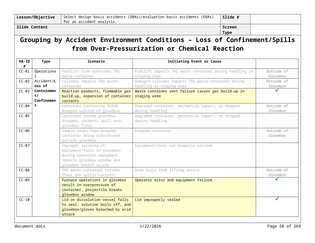
Lesson/Objective Select design basis accidents (DBAs)/evaluation basis accidents (EBAs) for an accident analysis. Slide #Slide Content Screen Type
Selecting Representative Bounding Accidents – Fire Outside the GloveboxID # Type Scenario Initiating Event or
CauseDescription Likelihood Consequence Risk Notes
P CW W P CW W
F-05 Operational Accident/Fire
Room fire ignites combustibles, spreads to glovebox, and glovebox breach
Electrical short Uncontrolled A H H H I I I
Controlled U L L M III III IIBuilding confinement ventilation system
Building structural integrity
Combustible loading program
Emergency Preparedness Program
Building and glovebox fire suppression system
Glovebox design integrity and confinement
F-07Operational Accident/Fire
Room fire spreads, engulfs shielding on sides of Pu238 glovebox, resulting in dispersal of Pu238 oxide
Ignition of transient combustibles such as plastic bags
Uncontrolled U H H H I I I
Controlled EU M M M III III III
Building confinement ventilation system
Building structural integrity
Combustible loading program
Emergency Preparedness Program
Building and glovebox fire suppression system
Glovebox design
document.docx 1/22/2016 Page 58 of 204

integrity and confinement
Narration<Bob> Let’s move on to the fire scenarios that initiate outside the glovebox. Both scenarios have high unmitigated consequences for both the public and co-located worker. However, scenario F-07 involves heat source plutonium which has a very high specific activity making it very radioactive and as a result requires heavy shielding for worker protection. The shielding provides a higher fire-fuel loading than scenario F-05. We’re going to select this scenario as the representative bounding scenario for fires that initiate outside of the glovebox. Feedback Instructions
Media Instructionssba130_01_02_22.mp3
document.docx 1/22/2016 Page 59 of 204

Lesson/Objective Select design basis accidents (DBAs)/evaluation basis accidents (EBAs) for an accident analysis. Slide #Slide Content Screen Type
Summary of Representative Bounding Accidents for Fire ScenariosSelect each group to view the representative bounding accident.
Fire Scenario Accident Initiator Controls1 Initiated inside
glovebox (enclosure fire)
F-02 – Ignition source (power tools, hotwork) Building confinement ventilation systemBuilding structural integrityCombustible loading programEmergency Preparedness ProgramBuilding and glovebox fire suppression systemGlovebox design integrity and confinement
F-03 – Pyrophoric, flammable (including combustibles) liquid, gas, or oxidizer material ignites
Building confinement ventilation systemBuilding structural integrityCombustible loading programEmergency Preparedness ProgramBuilding and glovebox fire suppression systemGlovebox design integrity and confinement
F-04 – Furnace temperature excursion (Bounding) Building confinement ventilation systemBuilding structural integrityCombustible loading programEmergency Preparedness ProgramBuilding and glovebox fire suppression systemGlovebox design integrity and confinementHigh-temp limiting switch
F-06 – Pyrophoric material ignites Building confinement ventilation systemBuilding structural integrityCombustible loading programEmergency Preparedness ProgramBuilding and glovebox fire suppression systemGlovebox design integrity and confinement
F-09 – Furnace controller malfunctions with Pu metal in glovebox Building confinement ventilation systemBuilding structural integrityCombustible loading programEmergency Preparedness ProgramBuilding and glovebox fire suppression systemGlovebox design integrity and confinement
F-10 – Electrical short (in glovebox) (Unique) Building confinement ventilation systemBuilding structural integrityCombustible loading programEmergency Preparedness ProgramBuilding and glovebox fire suppression systemGlovebox design integrity and confinementVessel design integrity
document.docx 1/22/2016 Page 60 of 204

2 Initiated outside glovebox (potential for small fire progression to large fire)
F-05 – Electrical short Building confinement ventilation systemBuilding structural integrityCombustible loading programEmergency Preparedness ProgramBuilding and glovebox fire suppression systemGlovebox design integrity and confinement
F-07 – Ignition of transient combustibles such as plastic bags (Bounding)
Building confinement ventilation systemBuilding structural integrityCombustible loading programEmergency Preparedness ProgramBuilding and glovebox fire suppression systemGlovebox design integrity and confinement
3 Initiated in waste staging area (potential pool fire)
F-01 – Forklift fuel tank damage, fuel leaks (Bounding) Building confinement ventilation systemBuilding structural integrityCombustible loading programEmergency Preparedness ProgramFire Protection ProgramBuilding and glovebox fire suppression systemVehicle fuel restrictionsTRU waste container design integrityMaintenance program
F-08 – Drum contents ignite combustibles Building confinement ventilation systemBuilding structural integrityCombustible loading programEmergency Preparedness ProgramFire Protection ProgramBuilding and glovebox fire suppression system
Narration<Bob> We now have a representative bounding accident for each group of fire scenarios, as well as one unique accident.Programming Instructions
Media Instructionssba130_01_02_23.mp3
document.docx 1/22/2016 Page 61 of 204

Lesson/Objective Select design basis accidents (DBAs)/evaluation basis accidents (EBAs) for an accident analysis. Slide #Slide Content Screen Type
Selecting Representative Bounding Accidents – Loss of Containment
Loss of Containment Scenario Accident Initiator1 Outside of the glovebox CC-01 – Forklift impacts TRU waste container
CC-02 – Damaged cylinder impacts TRU waste containerCC-04 – Degraded container of Pu-238 droppedCC-06 – Sample leaks from dropped containerCC-08 – Drum falls from lifting device
2 Inside the glovebox CC-05 – Degraded container dropped onto glovebox floorCC-07 – Improperly secured of equipment impacts glovebox window
3 Over-pressurization and/or chemical reactions CC-03 – Waste container vent failure causes gas build-upCC-09 – Equipment failure in furnace operations results in over-pressurization of containerCC-10 – Lid improperly sealed on dissolution vessel
Narration<Bob> We need to repeat the process of selecting the representative bounding accident for the loss of containment scenarios. Programming Instructions
Media Instructionssba130_01_02_24.mp3
document.docx 1/22/2016 Page 62 of 204

Lesson/Objective Select design basis accidents (DBAs)/evaluation basis accidents (EBAs) for an accident analysis. Slide #Slide Content Screen Type
Selecting Representative Bounding Accidents – Loss of Confinement/Spills Outside the Glovebox Knowledge Check
Select the representative bounding accident for this group. ID # Type Scenario Initiating Event or
CauseDescription Likelihood Consequence Risk Notes
P CW W P CW W
CC-01 Operational Accident/Loss of Containment
Forklift tine punctures TRU waste container
Forklift impacts TRU waste container during handling
Uncontrolled A L M M III II II
Controlled A L L L III III IIIBuilding confinement ventilation system
Building structural integrity
Emergency Preparedness Program
TRU waste container design integrity
Training and Qualification ProgramSpotter required
CC-02 Operational Accident/Loss of Containment
Cylinder impacts TRU waste container
Damaged cylinder impacts TRU waste container during handling
Uncontrolled A L M M III II II
Controlled A L L L III III IIIBuilding confinement ventilation system
Building structural integrity
Emergency Preparedness Program
TRU waste container design integrity
Training and Qualification Program
CC-04 Operational Accident/Loss of Containment
Container containing Pu238 dropped outside of glovebox
Degraded or damaged container dropped during handling
Uncontrolled A M H H II I I
Controlled U L L M III II II
document.docx 1/22/2016 Page 63 of 204

Container design integrity
Building confinement ventilation system
Building structural integrity
CC-06 Sample leaks from dropped container being transferred outside glovebox
Dropped container Uncontrolled U L L M III III II
Controlled EU L L L IV IV IVContainer design integrity
Building confinement ventilation system
Building structural integrity
CC-08 TRU waste container strikes floor and spills contents
Drum falls from lifting device
Uncontrolled A L M M III II II
Controlled U L L L III III IIITRU container design integrity
Building confinement ventilation system
Building structural integrity
Drum lift
Narration<Bob> We previously grouped these accidents together because they involve loss of containment outside of the glovebox. Which loss of containment scenario is the representative bounding accident? Programming InstructionsTry again. Which scenario has the highest unmitigated consequences to the co-located worker and the public? Incorrect. <Show visual feedback> This scenario has the highest unmitigated consequences to the co-located worker and the public. Notice that the remaining scenarios have unmitigated consequences that are below the EG for the public.Correct. Notice that the remaining scenarios have unmitigated consequences that are below the EG for the public.Media Instructionssba130_01_02_25.mp3
document.docx 1/22/2016 Page 64 of 204

Lesson/Objective Select design basis accidents (DBAs)/evaluation basis accidents (EBAs) for an accident analysis. Slide #Slide Content Screen Type
Selecting Representative Bounding Accidents –Loss of Confinement/Spills Inside the Glovebox Knowledge Check
Select the representative bounding accident for this group.
ID # Type Scenario Initiating Event or Cause
Description Likelihood Consequence Risk NotesP CW W P CW W
CC-05 Operational Accident/Loss of Containment
Container inside glovebox dropped, contents spill onto glovebox floor
Degraded container, mechanical impact, or dropped during handling
Uncontrolled U L L M III III II
Controlled EU L L L IV IV IVGlovebox design integrity
Building confinement ventilation system
Container design integrity
Building structural integrity
CC-07 Operational Accident/Loss of Containment
Improper securing of equipment in glovebox; during operation equipment impacts glovebox window and glovebox breach occurs
Equipment not properly secured
Uncontrolled A M H H II I I
Controlled U L L L III III IIIGlovebox design integrity
Building confinement ventilation system
Building structural integrity
Container design integrity
Equipment secured Narration<Bob> These are the loss of containment scenarios for inside the glovebox. Which scenario is the representative bounding accident? Feedback Instructions
document.docx 1/22/2016 Page 65 of 204

Try again. Which scenario has the highest unmitigated consequences for the co-located worker and the public. Incorrect. <highlight answer> This scenario has high consequences for the co-located worker and consequences that challenge the EG for the public. That’s correct. Media Instructionssba130_01_02_26.mp3
document.docx 1/22/2016 Page 66 of 204

Lesson/Objective Select design basis accidents (DBAs)/evaluation basis accidents (EBAs) for an accident analysis. Slide #Slide Content Screen Type
Selecting Representative Bounding Accidents – Loss of Confinement/Spills Over-pressurization and/or Chemical Reactions
ID # Type Scenario Initiating Event or Cause
Description Likelihood Consequence Risk Notes
P CW W P CW W
CC-03
Operational Accident/Loss of Containment
Reaction products, flammable gas build-up, expansion of container contents
Waste container vent failure causes gas build-up in staging area
Uncontrolled U L M M III II II Ci
Controlled U L L L III III IIIBuilding confinement ventilation system
Building structural integrity
TRU waste container design integrity (includes filtered vent)
Waste container inspection (vent and headspace gas analysis verification)
CC-09
Operational Accident/Loss of Containment
Furnace operations result in overpressure of container, projectile breaks glovebox window
Operator error and equipment failure
Uncontrolled A M H H II I I
Controlled U L L L III III IIIGlovebox design integrity and confinement
Container design integrity
Building confinement ventilation system
Building structural integrity
CC-10
Operational Accident/Loss of Containment
Lid on dissolution vessel fails to seal; solution boils off, and glovebox/ gloves breached by acid attack
Lid improperly sealed
Uncontrolled U H H H I I I
Controlled EU L L L IV IV IV
document.docx 1/22/2016 Page 67 of 204

Glovebox design integrity and confinement
Container design integrity
Vessel lid secured Building confinement ventilation system
Building structual integrity
Narration<Bob> This group of loss of confinement scenarios are initiated by over-pressurizations or chemical reactions. There are two representative bounding accidents. Scenario CC-03 addresses an over-pressurization of a container outside the glovebox. Scenario CC-10 addresses an over-pressurization chemical reaction accident inside a glovebox.Feedback Instructions
Media Instructionssba130_01_02_27.mp3
document.docx 1/22/2016 Page 68 of 204

Lesson/Objective Select design basis accidents (DBAs)/evaluation basis accidents (EBAs) for an accident analysis. Slide #Slide Content Screen Type
Selecting Representative Bounding Accidents – Loss of Confinement/Spills SummarySelect each group to view the representative bounding accident.
Loss of Containment Scenario Accident Initiator Controls1 Outside of the glovebox CC-01 – Forklift impacts TRU waste container Building confinement ventilation system
Building structural integrityEmergency Preparedness ProgramTRU waste container design integrity
CC-02 – Damaged cylinder impacts TRU waste container
Building confinement ventilation systemBuilding structural integrityEmergency Preparedness ProgramTRU waste container design integrity
CC-04 – Degraded container of Pu-238 dropped
Container design integrityBuilding confinement ventilation systemBuilding structural integrity
CC-06 – Sample leaks from dropped container Container design integrityBuilding confinement ventilation systemBuilding structural integrity
CC-08 – Drum falls from lifting device TRU container design integrityBuilding confinement ventilation systemBuilding structural integrity Drum lift
2 Inside the glovebox CC-05 – Degraded container dropped onto glovebox floor
Glovebox design integrityBuilding confinement ventilation systemContainer design integrityBuilding structural integrity
CC-07 – Improperly secured of equipment impacts glovebox window
Glovebox design integrityBuilding confinement ventilation systemContainer design integrityBuilding structural integrity
3 Over-pressurization and/or chemical reactions
CC-03 – Waste container vent failure causes gas build-up
Building confinement ventilation system Building structural integrity TRU waste container design integrityWaste container inspection
CC-09 – Equipment failure in furnace operations results in over-pressurization of container
Glovebox design integrity and confinementContainer design integrityBuilding confinement ventilation systemBuilding structural integrity
CC-10 – Lid improperly sealed on dissolution vessel
Glovebox design integrity and confinementContainer design integrityVessel lid securedBuilding confinement ventilation systemBuilding structural integrity
Narration
document.docx 1/22/2016 Page 69 of 204

<Bob> We now have a representative bounding accident for each group of the loss of confinement scenarios. Programming InstructionsWhen user selects a marker, show the following: This representative bounding accident will address “outside glovebox containers,” which will include TRU waste containers as well as SNM containers. This representative bounding accident will address “inside glovebox containers.”Media Instructionssba130_01_02_28.mp3
document.docx 1/22/2016 Page 70 of 204

Lesson/Objective Select design basis accidents (DBAs)/evaluation basis accidents (EBAs) for an accident analysis. Slide #Slide Content Screen Type
Selecting Representative Bounding Accidents – NPH
ID # Type Scenario Initiating Event or Cause
Description Likelihood Consequence Risk NotesP CW W P CW W
NPH-01 Natural Phenomena/Wildfire
Grass/brush fire in fields impacts TRU waste containers staged outside (potential for fire to spread to the building)
Wildfire adjacent to site
Uncontrolled A H H M I I II MAR – Site limit (1,800 PE-Ci)
Controlled A L L L III III IIICombustible loading program
Emergency Preparedness Program
TRU waste container staging practices
TRU waste container design integrity
Vegetation exclusion area
NPH-02 Natural Phenomena/Lightning
Ignition of combustibles impacts TRU waste containers staged outside (potential for fire to spread to the building)
Lightning causes fire in yard and/or container
Uncontrolled A H H H I I I MAR – Site limit (1,800 PE-Ci)
Controlled U L L L III III IIICombustible loading control
Emergency Preparedness Program
TRU waste container staging practices
TRU waste container design integrity
Lightning Protection System
document.docx 1/22/2016 Page 71 of 204

Vegetation exclusion area
NPH-03 Natural Phenomena/Seismic Event
Fire and structural debris impact glovebox
Seismic event initiates electrical fire inside building and fire spreads outside
Uncontrolled EU H H H II II II MAR – Site Limit (1,800 PE-Ci)
Controlled EU L L L IV IV IVBuilding confinement ventilation system
Building structural integrity
Combustible loading program
Emergency Preparedness Program
Building and glovebox fire suppression system
Waste container design integrity
Glovebox design integrity and confinement
Glovebox drum lift design integrity
Waste container staging practices
Vegetation exclusion area
NPH-04 Natural Phenomena/Seismic Event
Structural damage to building, debris impacts TRU waste containers
Seismic event Uncontrolled U L M M III II II MAR –1800 PE-Ci
Controlled U L L L III III IIIBuilding confinement ventilation system
Building structural integrity
Emergency Preparedness Program
Waste container design integrity
document.docx 1/22/2016 Page 72 of 204

Waste container staging practices
Glovebox design integrity and confinement
Glovebox drum lift design integrity
NPH-05 Natural Phenomena/High Wind
Structural damage to building and debris breach TRU waste containers
High wind Uncontrolled U L M M III II II MAR –800 PE-Ci
Controlled U L L L III III IIIBuilding structural integrity
Emergency Preparedness Program
TRU waste container staging practices
TRU waste container design integrity
Glovebox design integrity and confinement
Narration<Bob> Let’s examine the accidents for the NPH events. We have several scenarios with high unmitigated consequences for both the co-located worker and the public. There are two representative bounding accidents. NPH-01 is selected because the likelihood remains anticipated and NPH-03 which is the seismic event that initiates a fire. Feedback Instructions
Media Instructionssba130_01_02_29.mp3
document.docx 1/22/2016 Page 73 of 204

Lesson/Objective Select design basis accidents (DBAs)/evaluation basis accidents (EBAs) for an accident analysis. Slide #Slide Content Screen Type
Selecting Representative Bounding Accidents – External Manmade Events Knowledge CheckSelect the two representative bounding accident for this group.
ID # Type Scenario Initiating Event or Cause
Description Likelihood
Consequence Risk NotesP CW W P CW W
EE-01 External Event/Fire
Fire spreads impacting TRU waste containers staged outside
Vehicle (not facility related) or refueling truck accident adjacent to site causes fuel leak
Uncontrolled U H H H I I I MAR – Site limit (1,800 PE-Ci)
Controlled EU M M M III III IIICombustible loading program
Emergency Preparedness Program
TRU waste container staging practices
TRU waste container design integrity
Vehicle access system
Vehicle barrier
EE-02 External Event/Aircraft Crash
Aircraft crash Aircraft crashes into staging area or building causing a full facility (inside and outside) fire
Uncontrolled EU H H H II II II MAR – Site limit (1,800 PE-Ci)
Controlled EU H H H II II IICombustible loading programEmergency Preparedness Program
TRU waste container staging practices
TRU waste container design integrity
Vegetation exclusion area
EE-03 External Event/Explosion
TRU waste containers
Vehicle impacts staged waste containers (not
Uncontrolled U L M M III II II MAR – Several
document.docx 1/22/2016 Page 74 of 204

impacted facility-related) containers (1,800 PE-Ci)
Controlled EU L L L IV IV IVEmergency Preparedness Program
TRU waste container staging practices
TRU waste container design intregity
Vehicle access system
Vehicle barrier EE-04 External
Event/Station Blackout
Loss of AC power results in loss of ventilation (direct current power is not assumed available)
Equipment malfunction or natural event
Uncontrolled A L L L III III III
Controlled A L L L III III IIIBuilding structural integrity
TRU waste container design integrity
Narration<Bob> Let’s examine one more group of accident scenarios for the external man-made events. There are also two representative bounding accidents for this group. Which accidents have the highest unmitigated consequences? Feedback InstructionsTry again. Incorrect. <Show visual feedback> Both EE-01 and EE-02 have high unmitigated consequences to the public and co-located worker. Both are representative bounding man-made external accidents.That’s correct.Media Instructionssba130_01_02_30.mp3
document.docx 1/22/2016 Page 75 of 204

Lesson/Objective NA Slide #Slide Content Screen Type
Selecting DBAs/EBAs ProcessSelect each step to learn more.
Narration
Programming Instructions
Media Instructions
document.docx 1/22/2016 Page 76 of 204
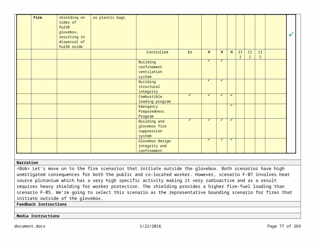
Lesson/Objective Select design basis accidents (DBAs)/evaluation basis accidents (EBAs) for an accident analysis. Slide #Slide Content Screen Type
Screening Accidents From SelectionSelect each accident type to learn more.
Operational
According to DOE-STD-3009, Section 3.2.1, any operational events that are deemed not plausible according to the criteria below may be excluded as candidates for DBAs/EBAs.
An operational event is not considered plausible if it is either:
A process deviation that consists of a sequence of many unlikely human actions or errors for which there is no reason or motive. In evaluating this criterion, a wide range of possible motives (short of intent to cause harm) should be considered. Necessarily, no such sequence of events may ever have actually happened in any nonreactor nuclear facility; or
A process deviation for which there is a convincing argument (given physical laws). The criterion cannot be used if the argument depends on any feature of the design or materials controlled by the facility’s safety features or administrative controls (ACs).
According to DOE-STD-3009, use of a lower binning likelihood threshold such as 10-6/yr (i.e., beyond extremely unlikely) for screening operational events from selection as DBA/EBAs is not appropriate. However, a probabilistic risk assessment (PRA) plan (approved by DOE), may be used to support decisions regarding the need for safety class (SC) or safety significant (SS) controls for operational events. The PRA must include an assessment of the probability and consequences of the accident to establish the events risk significance. When PRA results are used, key assumptions and initial conditions shall be identified and protected.
Natural Phenomena
According to DOE-STD-3009, Section 3.2.1, natural phenomena initiators of greater magnitude than those required by DOE O 420.1C (or applicable successor documents) may be excluded.
The likelihood/frequency and severity/consequence of NPH events are initially addressed in Chapter 1 of the DSA (Site Characteristics) through discussion of natural event accident initiators. A summary of assumptions supporting the analysis in Chapter 3 should be included in Chapter 1 (e.g., assumptions supporting the estimates for the likelihood and consequence of NPH events should be discussed).
The evaluation of natural phenomena hazards is directed by DOE O 420.1C and its standard DOE-STD-1020-2012. The evaluation is based on the following process:
1. Collection and/or investigations of site-specific natural phenomena hazard data (e.g., paleoseismic investigations, wind data, precipitation data, etc.)
2. Performance of natural phenomena hazard assessments as directed by DOE-STD-1020-2012 (e.g., probabilistic seismic hazard assessment)
document.docx 1/22/2016 Page 77 of 204
This natural phenomena hazard evaluation process is outlined in DOE-STD-1020-2012 and results in the determination of the magnitude of the NPH event.
This process also results in identifying the likelihood of the event addressed as the return period. The return period is the inverse of the probability that the event will be exceeded in any one year (or the inverse of the expected number of occurrences in a year). For example, a 10 year flood has a 10% (1/10 = 0.1) chance of being exceeded in any one year. A 50 year flood has a 2% (1/50 = 0.02) chance of being exceeded in any one year.
Determining the magnitude of the NPH allows for a consequence level to be assigned (using the consequence thresholds in Table 1 of DOE-STD-3009). The process is based on industry codes and standards and is focused on meeting performance goals that are consistent with DOE Safety Policy. Therefore, the consideration of NPH events of greater magnitude than those identified through the DOE-STD-1020-2012 process is not warranted in terms of selection as DBAs/EBAs.
For additional information on determining the magnitude of NPH events, refer to DOE O 420.1C and DOE-STD-1020-2012.
External Man-Made
According to DOE-STD-3009, Section 3.2.1, external man-made accidents with a cutoff likelihood of 10-6/yr (conservatively calculated), may be excluded.
For information on determining quantitative likelihood estimates for aircraft accidents, refer to DOE-STD-3014-2006, Accident Analysis for Aircraft Crash into Hazardous Facilities.
Narration<Bob> Now that we’ve identified both the representative and unique accident scenarios, we need to determine if we need to screen any accidents from selection. DOE-STD 3009, Section 3.2.1, provides criteria for screening operational, natural phenomena, and external man-made event accident scenarios from selection. Programming InstructionsAdd icon for DOE-STD-1020 and DOE O 420.1C. Add graphic for NPH process. Media Instructionssba130_01_02_31.mp3
document.docx 1/22/2016 Page 78 of 204

Lesson/Objective NA Slide #Slide Content Screen Type
Screening Knowledge Check
Which of the following accident scenarios should be screened from selection based on Section 3.2.1 of DOE-STD-3009?
ID # Type Scenario Initiating Event or Cause Description Likelihood Consequence RiskP CW W P CW W
EE-05 External Event/Fire
Fuel tanker collision resulting in pool fire
Fuel tanker collides with transport trailer carrying DOT Type B Shipping Container
Uncontrolled BEU H H H III III III
EE-06 External Event/Fire
Large fuel spill ignites causing large fire that impacts TRU waste containers
During refueling of auxiliary generator tank, accident causes fuel spill and fuel ignites
Uncontrolled U H H H I I I
EE-07 External Event/Fire
TRU waste storage fire During maintenance activities adjacent to TRU waste storage, equipment malfunction results in sparks and ignites combustibles, spreading to TRU waste containers
Uncontrolled EU L M M IV III III
Narration<Bob> Let’s examine a few more man-made external accidents to determine if any can be screened from selection based on the guidelines in DOE-STD-3009.Programming InstructionsTry again. According to DOE-STD-3009, Section 3.2.1, external man-made accidents with a cutoff likelihood of 10-6/yr (conservatively calculated), may be excluded.Incorrect. <Show visual feedback> The accident scenario resulting from a fuel tanker collision has a likelihood of Beyond Extremely Unlikely, which is below the cutoff of 10-6. Correct.Media Instructionssba130_01_02_32.mp3
document.docx 1/22/2016 Page 79 of 204

Lesson/Objective NA Slide #Slide Content Screen Type
Selecting DBAs/EBAs ProcessSelect each step to learn more.
Narration
Programming Instructions
Media Instructions
document.docx 1/22/2016 Page 80 of 204
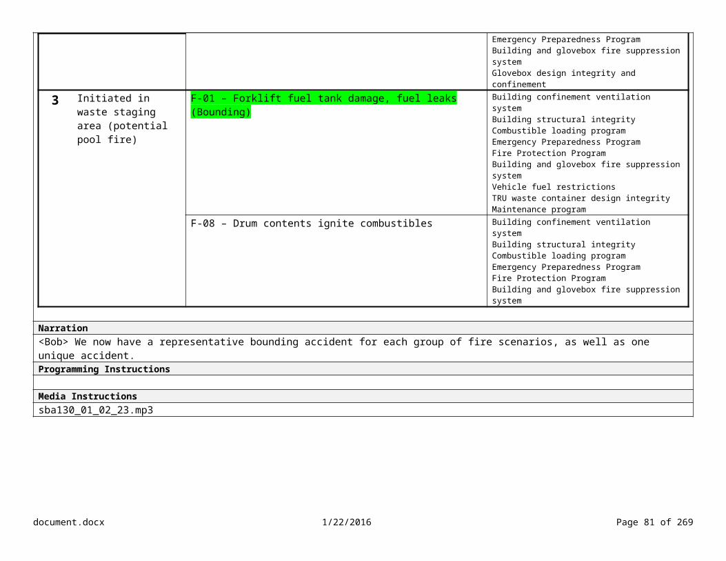
Lesson/Objective Select design basis accidents (DBAs)/evaluation basis accidents (EBAs) for an accident analysis.Identify the requirements for documenting an accident analysis.
Slide #
Slide Content Screen Type
Documenting the DBA/EBA Selection Knowledge CheckWhich of the following items should be documented in Section 3.4.2 of the DSA (refer to Section 4 of DOE-STD-3009). Select all that apply.
Comparison of radiological consequences to the EG
Categories of operational accidents, natural events, and man-made external events
Accident type (e.g., fire, explosion, spill, etc.)
Whether the accident is representative or unique
Narration<Bob> When you review the DSA, you need to ensure that the accident selections are documented in the DSA. The requirements for documenting the selections are located in Section 4 of DOE-STD-3009.Programming InstructionsTry again. Take another look at the requirements for Section 3.4.2 of the DSA (located in Section 4 of DOE-STD-3009). Incorrect. Section 3.4.2 of the DSA should identify the categories of operational accidents, natural events, and man-made external events; accident type; and whether the accident is representative or unique. The comparison of radiological consequences to the EG is documented in Section 3.4.3 of the DSA. Correct. Media InstructionsAdd icon for DOE-STD-3009sba130_01_02_33.mp3
document.docx 1/22/2016 Page 81 of 204
SUBMIT

Lesson/Objective Select design basis accidents (DBAs)/evaluation basis accidents (EBAs) for an accident analysis.Identify the requirements for documenting an accident analysis.
Slide #
Slide Content Screen Type
Documenting the DBA/EBA Selection
Review the key points about documenting the accident selection.
DBAs/EBAs may be identified for other accidents if not quantitatively evaluated in the hazard evaluation and included in DSA Section 3.3.2.3. Examples include radiological exposures to the co-located worker or chemical exposures to the public and co-located worker.
In the case of representative accidents, the bounded hazard scenarios are identified.
If operational accidents are not selected as DBAs/EBAs based on the PRA results, a summary is provided that describes them and states that they are further evaluated in the DSA Section 3.5 as beyond DBAs/EBAs.
Narration<Bob> There are a few more items that you need to know about documenting the accident selection process. Programming Instructions Media Instructionssba130_01_02_34.mp3
document.docx 1/22/2016 Page 82 of 204

Lesson/Objective Select design basis accidents (DBAs)/evaluation basis accidents (EBAs) for an accident analysis.Identify the requirements for documenting an accident analysis.
Slide #
Slide Content Screen Type
Section 4.2 of the DSA – Accident Selection
Select each category to view the EBAs documented in the Section 3.4.2 of the DSA. Category Event Type Accident Initiator Representative Bounding Accident
and/or Unique AccidentBounded HE Scenarios
Operational Accident
Fire Initiated inside glovebox (enclosure fire)
F-04 - Furnace temperature excursion F-02 – Ignition source (power tools, hotwork) F-03 – Pyrophoric, flammable (including combustibles) liquid, gas, or oxidizer material ignitesF-06 – Pyrophoric material ignitesF-09 – Furnace controller malfunctions with Pu metal in glovebox
F-10 – Electrical short (in glovebox) (Unique)
Initiated outside glovebox (potential small fire progression to large fire)
F-07 – Ignition of transient combustibles such as plastic bags
F-05 – Electrical short
Initiated in waste staging area (potential pool fire)
F-01 – Forklift fuel tank damage, fuel leaks
F-08 – Drum contents ignite combustibles
Loss of Containment
Outside of the glovebox CC-04 – Degraded container of Pu-238 dropped
CC-01 – Forklift impacts TRU waste containerCC-02 – Damaged cylinder impacts TRU waste containerCC-06 – Sample leaks from dropped containerCC-08 – Drum falls from lifting device
Inside the glovebox CC-07 – Improperly secured of equipment impacts glovebox window
CC-05 – Degraded container dropped onto glovebox floor
Over-pressurization and/or chemical reactions
CC-03 – Waste container vent failure causes gas build-up
CC-10 – Lid improperly sealed on dissolution vessel
CC-09 – Equipment failure in furnace operations results in over-pressurization of container
NPH
NPH-01 – Wildfire adjacent to site
NPH-03 – Seismic event initiates electric fire
NPH-02 – Lightning causes fire in yard and/or containerNPH-04 – Seismic event causes structural damage to building NPH-05 – High wind
Man-Made External Events
EE-01 – Vehicle accident causes fuel leak and fire
EE-03 – Vehicle impacts staged waste containerEE-04 – Loss of AC power
document.docx 1/22/2016 Page 83 of 204

EE-02 – Aircraft crash
Narration<Bob> Here is an example of the facility EBAs in terms of categories of operational accidents, natural events, and man-made external events, accident types, and whether the accident is representative or unique. This information would be documented in Section 3.4.2 of the DSA. Programming Instructions Media Instructionssba130_01_02_35.mp3
document.docx 1/22/2016 Page 84 of 204
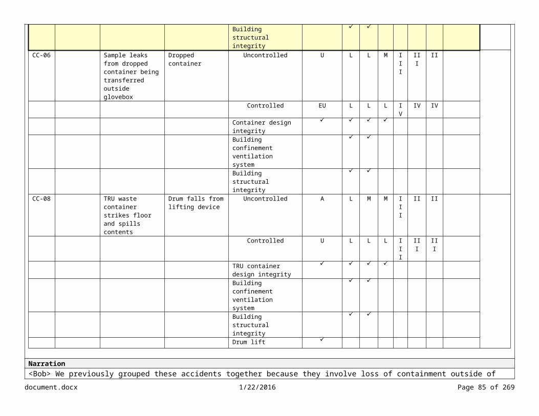
Lesson/Objective NA Slide #Slide Content Screen Type
Ask BobWhat is your question?
What is a probabilistic risk assessment (PRA)?
What is a NPH design category (NDC)?
What are the NPH requirements for new facilities?
What are the NPH assessment requirements for existing facilities?
How are aircraft crash accidents screened? Programming Instructions1st Question Answer: According to DOE-STD-1628, a PRA is a qualitative and quantitative assessment of the risk associated with facility operation and maintenance that is measured in terms of frequency of occurrence of risk. A PRA methodology can augment existing DOE safety assessment methods by providing input to the definition and selection of design basis events. PRA results can enhance DOE decisions on defense-in-depth by providing information on the importance of each control making up the defense-in-depth strategy and by providing risk insights needed to balance prevention and mitigation strategies. In addition, PRAs can inform the design process, especially for complex, high-hazard facilities.
For additional information on PRAs, refer to DOE-STD-1628, Development of Probabilistic Risk Assessments for Nuclear Safety Applications.
2nd Question Answer: During design of a new facility, each SSC in a DOE facility is assigned to a category depending upon its safety importance. Each category is assigned a target performance goal in terms of the probability of unacceptable damage due to natural phenomena. The SSCs are categorized into the following NDC.
NPH Categories ReferencesSeismic Seismic design category (SDC) 1-5 ASCE/SEI 7-10
ANSI/ANS-2.26-2004 ASCE/SEI 43-05ANSI/ANS-2.27-2008ANSI/ANS-2.29-2008
Extreme wind, tornado, and hurricane
Wind design category (WDC) 1-5 ASCE/SEI 7-10ANSI/ANS 2.3-2011
Flood, seiche, and tsunami Flood design category (FDC) 1-5 International Building CodeASCE/SEI 7-10
Extreme precipitation Precipitation design category (PDC) 1-5 ASCE/SEI 7-10Volcanic eruption Volcanic design category (VDC) 1-5 ASCE/SEI 43-05
ASCE/SEI 7-10ASCE/SEI 43-05
document.docx 1/22/2016 Page 85 of 204

ACE-349-06ANSI N690-06
For additional information on the process for determining an NPH design category (NDC), refer to ANSI/ANS-2.26-2004.
3rd Question Answer: Facilities must be designed, constructed, maintained, and operated to ensure that SSCs will be able to perform their intended safety functions effectively under the combined effects of NPH and normal loads. All new facilities and major modifications must satisfy the applicable requirements and criteria contained in DOE-STD-1020, Natural Phenomena Hazards Analysis and Design Criteria for DOE Facilities.
4th Question Answer: NPH assessments for existing facilities must be reviewed at least every 10 years to identify any significant changes in data, criteria, and assessment methods that would warrant updating the assessment. If a review of NPH indicates deficiencies in the existing SSC design, a plan for upgrades must be developed.
For information on the criteria and guidance for NPH reviews, refer to Sections 9.0 through 9.3 of DOE-STD-1020, Natural Phenomena Hazards Analysis and Design Criteria for DOE Facilities.
5th Question Answer: According to DOE-STD-3009, Section 3.2.1, external man-made accidents with a cutoff likelihood of 10-6/yr (conservatively calculated) may be screened from selection as DBAs/EBAs. DOE-STD-3014-2006 provides guidelines for determining the quantitative likelihood estimates for aircraft accidents. It also includes information for determining the potential for an accident producing significant offsite or onsite consequences.Media Instructions
document.docx 1/22/2016 Page 86 of 204

Lesson/Objective Select design basis accidents (DBAs)/evaluation basis accidents (EBAs) for an accident analysis.Outline the process for performing an accident analysis.
Slide #
Slide Content Screen TypeDBA/EBA Selection Process Knowledge Check
Drag and drop each label to the appropriate step.
Narration
Programming InstructionsImmediate feedback on correct drops.Try again. Incorrect. <Show correct answers>That’s correct.Media Instructions
document.docx 1/22/2016 Page 87 of 204
Submit
Categorize Accidents
Document Selection
Screen Accidents
Identify Unique Accidents
Select Representative Bounding Accident from Each Group
Group Accidents
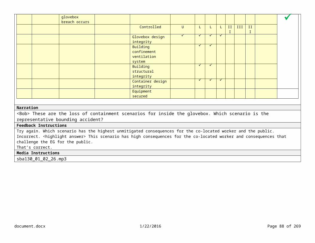
Lesson/Objective Select design basis accidents (DBAs)/evaluation basis accidents (EBAs) for an accident analysis.Identify the requirements for documenting an accident analysis.Outline the process for performing an accident analysis.
Slide #
Slide Content Screen Type
Key Points 1. Select DBAs/EBAs
DBAs are identified during the design of new facilities or during major modifications. EBAs are derived from hazard scenarios identified during the hazard evaluation process for existing facilities. When an adequate set of DBAs does not exist, select the EBAs from three categories: operational accidents, natural events, and man-
made external events.
2. Group accidents by event type (e.g., fire, explosion, loss of containment, nuclear criticality, external events, natural phenomena), conditions, and environment.
3. Select a representative bounding accident from each group. Select the accident with the highest unmitigated consequences for the public and co-located worker (within each group). Ensure that the representative accident selected has similar controls, conditions, and environment as the other accidents in that group. Select at least one bounding accident from each of the major types that has the potential to challenge the EG and/or exceed the co-
located worker threshold.
4. Identify unique accidents based on unique controls sets, accident conditions, or environment.
5. Screen accidents from selection using DOE-STD-3009, Section 3.2.1. Refer to criteria in Section 3.2.1 for screening operational events deemed not plausible. Natural phenomena initiators of greater magnitude than those required by DOE O 420.1C (or applicable successor documents) may be
excluded. External man-made accidents with a cutoff likelihood of 10-6/yr (conservatively calculated), may be excluded.
6. Document selection of DBAs/EBAs in Section 3.4.3.X of the DSA. According to Section 4 of DOE-STD-3009, Section 3.4.2 of the DSA must identify the DBA or EBA by individual title, category, and type.
Narration
Programming Instructions
Media Instructions
document.docx 1/22/2016 Page 88 of 204

Lesson/Objective NA Slide #Slide Content Screen Type Menu
Menu
Purpose and Scope
Selecting DBAs/EBAs
Developing Formal Descriptions
Determining Quantified Likelihood Estimates
Calculating Radiological Source Term
Calculating Radiological Dose
Comparing Consequence Estimates to the EG and/or CW Threshold
Narration
Programming Instructions
Media Instructions
document.docx 1/22/2016 Page 89 of 204
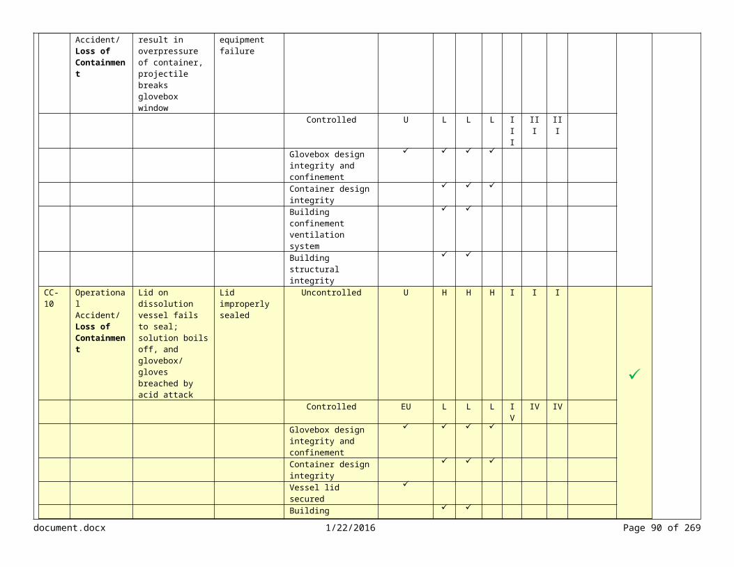
Lesson/Objective NA Slide #Slide Content Screen Type
Developing Formal Descriptions of Accident Scenarios
Select each step to learn more.
Narration<Bob> After completing the selection process, we need to develop formal descriptions of the accident scenarios. This process documents the accident progression from the initiating event through all subsequent events.Programming Instructions
Media Instructionssba130_01_03_01.mp3
document.docx 1/22/2016 Page 90 of 204
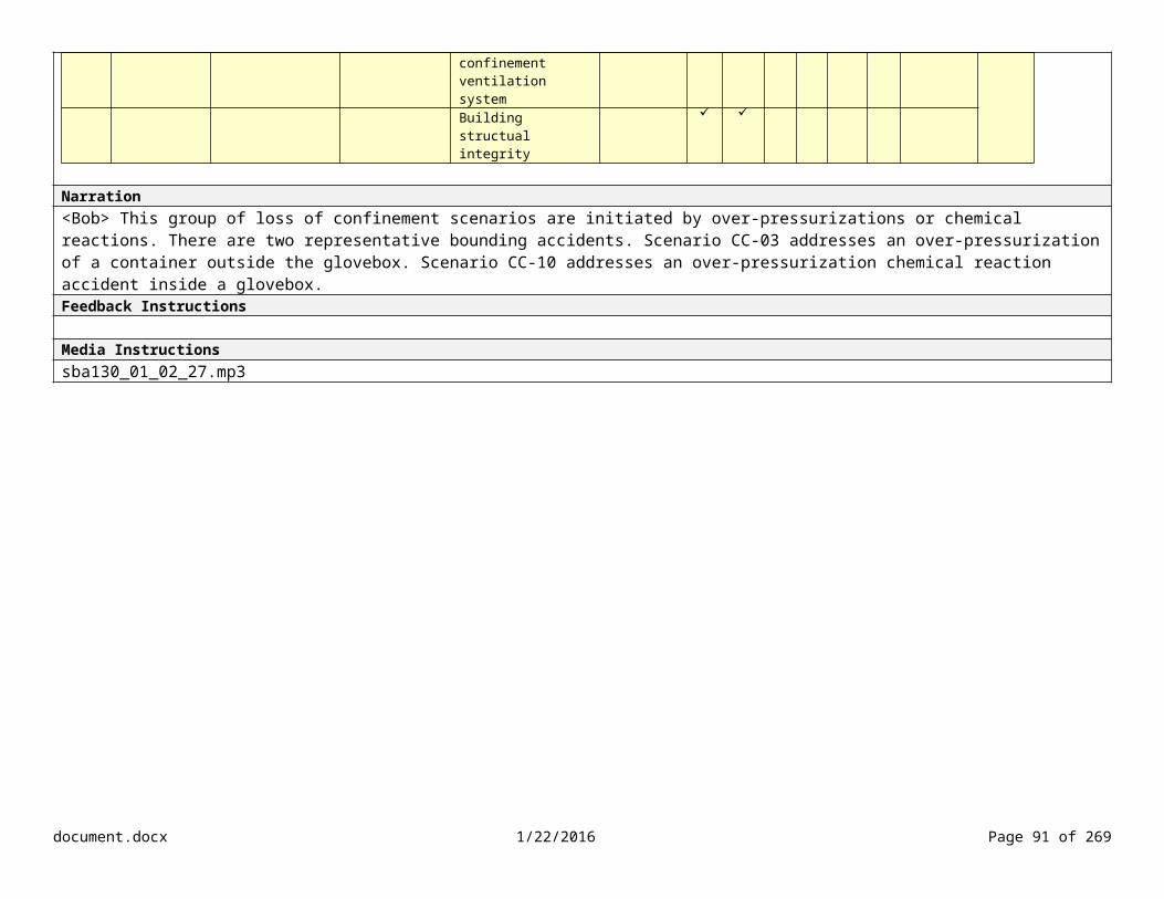
Lesson/Objective Identify the requirements for documenting an accident analysis. Slide #Slide Content Screen Type
Determining Inputs/Assumptions ActivityWhat is the difference between inputs and assumptions? Drag and drop the label to the appropriate image.
Volume of a Tank
Rate of Dispersion of Flammable Gas
Metal Skin Thickness of 55-Gallon Drum
Degree of Reaction/Interaction
Between Spilled Chemicals
Input Assumption Input Assumption
Narration<Bob> The foundation of any accident analysis can be reduced to a set of inputs, initial conditions, and assumptions. DOE-STD-3009-2014 requires that calculations be made based on technically justifiable input parameters and underlying assumptions such that the overall consequence calculation is conservative. Let’s see if you know the difference between inputs and assumptions. We’ll discuss initial conditions next.
<Bob Feedback> An input is a value feeding into the analyses that can be measured confidently and is readily obtainable. An input value would not be expected to change. Examples of inputs include the volume of a tank and the metal thickness of a 55-gallon drum.
An assumption is a value feeding into the analysis that is not known with reliability and accuracy. Significant judgment is required when selecting the value or parameter. Examples of assumptions include the rate of dispersion of a flammable gas leaked into a ventilated volume and the degree to which two spilled chemicals intermingle and react.
Programming InstructionsNot gradedImmediate visual feedbackMedia Instructionssba130_01_03_02.mp3
document.docx 1/22/2016 Page 91 of 204
Input Assumption

sba130_01_03_03.mp3
Lesson/Objective Identify the requirements for documenting an accident analysis. Slide #Slide Content Screen Type
Determining Inputs and Assumptions for the GloveboxSelect each marker to learn more.
Narration<Bob> Let’s take a closer look at the inputs and assumptions for the glovebox.
Programming Instructions Input – The volume of the glovebox can be calculated from the dimensions.
Input – Gloveboxes have heat detectors that sound an alarm at 60°C (140
document.docx 1/22/2016 Page 92 of 204

°F). If the glovebox contains a furnace, the heat detectors sound an alarm at 88°C (190°F).
Assumption – The speed at which gloves are breached during a fire is dependent on several factors, such as the temperature and size of the fire. Gloves used in heat-source processing areas are a laminate of Hypalon® and Neoprene, with degradation known to occur at temperatures ~392 ºF. Assumption – The maximum temperature for a typical glovebox fire is between 225 ºF and 300 ºF. Input – The room fire suppression system sprinklers activate at 155 °F. Assumption – If the ventilation system is operating at the time of the fire, some portion of the aerosol is carried to HEPA filters where it potentially becomes trapped. Smoke can also impact HEPA filters causing them to clog. Input – The high-temperature HEPA filters are rated for continuous service up to 500 °F. Assumption – Gloveboxes that handle large quantities of plutonium metals or oxides may use polymethyl methacrylate (PMMA) shielding to protect workers from exposure. However, PMMA can be a fuel source during fires, especially if there are combustibles adjacent to the PMMA. PMMA softens at approximately 100°C and self-ignites at approximately 450 °C.Media Instructionssba130_01_03_04.mp3
Lesson/Objective Identify the requirements for documenting an accident analysis. Slide #Slide Content Screen Type
Determining Initial ConditionsHA-ID
# Type Scenario Initiating Event or Cause Description Likelihood Consequence Risk Notes
P CW W P CW W
F-04 Operational Accident/Fire
Furnace temperature excursion, combustibles adjacent to furnace, fire inside glovebox, and glovebox breach
Furnace malfunction Uncontrolled U H H H I I I MAR – 9,000 g of Pu
Narration<Bob> During the hazard evaluation, we identified the initial conditions for the hazard scenarios. Remember that initial conditions are specific assumptions regarding a facility and its operations. It is not appropriate to credit administrative controls or safety management program controls as initial conditions during the unmitigated accident analysis. An exception is material at risk inventory (or MAR) limits.
Per DOE-STD-3009, the MAR values used during the accident analysis must be consistent with the values noted in the hazard identification and evaluation. Also, the MAR value must be bounding with respect to each accident being evaluated.
The initial condition for the representative bounding accident for the furnace malfunction scenario is a MAR inventory limit of 9,000 g of plutonium.
Programming Instructions
Media Instructionssba130_01_03_05.mp3
document.docx 1/22/2016 Page 93 of 204

Lesson/Objective NA Slide #Slide Content Screen Type
Developing Formal Descriptions of Accident Scenarios
Select each step to learn more.
Narration
Programming Instructions
Media Instructions
document.docx 1/22/2016 Page 94 of 204

Lesson/Objective Identify the requirements for documenting an accident analysis. Slide #Slide Content Screen Type
Determining Accident Phenomena
Narration<Bob> The next step in the process is to determine the accident phenomena (or phenomenological modeling). This step involves performing calculations to understand the dynamics of the accident conditions and to demonstrate the effectiveness of either preventive or mitigative safety controls. Phenomenological modeling helps us understand the routes by which radioactive material is released and the processes involved in the transport and movement of materials released to the atmosphere. There are specific phenomenological models for fires, explosions, heat transfer, fluid mechanics, and radiation transport. These models help determine the system response to each phenomena.
The inputs, assumptions, and initial conditions are important factors in the phenomenological models. For example, all the events from the initiating event to subsequent events during a release of flammable material are time-dependent and happen in a chain. Inaccuracy in any one input, assumption, or initial condition may result in large under- or over-predictions of the final event in the chain. For example, a liquid fire in a room and a fire that starts in an enclosure such as a glovebox result in different source terms.
Phenomenological modeling is typically performed by a specialist using software and tools that are specific to the phenomena being analyzed.
Any software used during phenomenological modeling must be identified within the quality assurance program. For additional information, refer to DOE O 414.1D, Quality Assurance, and DOE G 414.1-4, Safety Software Guide for use with 10 CFR 830 Subpart A, Quality Assurance Requirement.Programming Instructions
Media Instructionssba130_01_03_06.mp3
document.docx 1/22/2016 Page 95 of 204

Lesson/Objective NA Slide #Slide Content Screen Type
Developing Formal Descriptions of Accident Scenarios
Select each step to learn more.
Narration
Programming Instructions
Media Instructions
document.docx 1/22/2016 Page 96 of 204
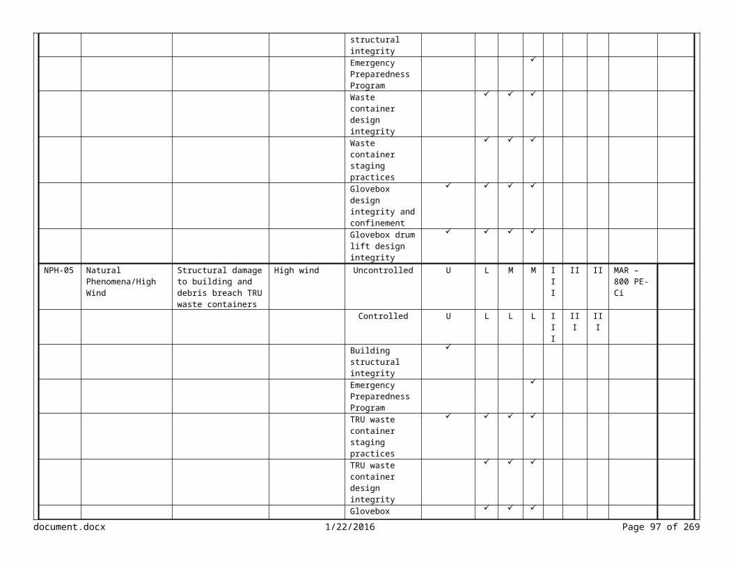
Lesson/Objective Identify the requirements for documenting an accident analysis. Slide #Slide Content Screen Type
Determining Accident ProgressionSelect each for an enlarged view.
HA-ID #
Type Scenario Initiating Event or Cause
Description Likelihood Consequence Risk NotesP CW W P CW W
F-04 Operational Accident/Fire
Furnace temperature excursion, combustibles adjacent to furnace, fire inside glovebox, and glovebox breach
Furnace malfunction
Uncontrolled U H H H I I I MAR – 9,000 g of Pu
Controlled EU L L M IV IV IIIBuilding confinement ventilation system
Building structural integrity Combustible loading program Emergency Preparedness Program
Building and glovebox fire suppression system
Glovebox design integrity and confinement
High-temp limiting switch
Narration<Bob> The next step is to determine the accident progression. Accident progression links the initiating event with the preventive and mitigative controls and other contributing phenomena. Accident progression can be represented using a table or event tree. The event tree graphically illustrates the possible outcomes or pathways to a release. The initiating event is typically expressed as a frequency or likelihood, such 0.04 times per year. The success or failure of each control is typically expressed as a probability (or number of events per demand).
document.docx 1/22/2016 Page 97 of 204

Section 4 of DOE-STD-3009 does not require a quantified evaluation in Section 3.4.3.X.1 of the DSA. However, the rationale for the unmitigated likelihood assigned to the accident during the hazard evaluation should be provided and a summary for the initiating event and accident progression should include relevant information. Programming InstructionsWhen learner selects each image, show enlarged view in lightbox.Media Instructionssba130_01_03_07.mp3
document.docx 1/22/2016 Page 98 of 204
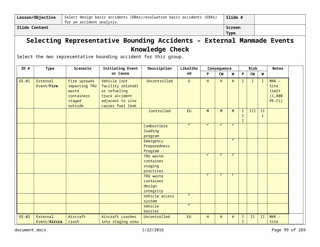
Lesson/Objective Identify the requirements for documenting an accident analysis. Slide #Slide Content Screen Type
Event Tree
Narration<Bob> Let’s take a closer look at the event tree for the furnace malfunction. The combustible loading program reduces the amount of combustibles in the glovebox at the time of the furnace malfunction.
If a furnace malfunction occurs and there is no combustible loading control, a fire can ignite in the glovebox. If there is a fire in the glovebox, the glovebox heat sensor triggers initiating the glovebox fire suppression system, extinguishing the fire.
If the glovebox fire suppression system does not extinguish the fire, then the glovebox confinement may be breached. If the glovebox confinement fails, then the aerosol is released into the ventilation system. If the ventilation system is operating, then the released aerosol is trapped in the HEPA filters. If the HEPA filters become plugged or fail, then the aerosol is released into the building.
document.docx 1/22/2016 Page 99 of 204

If the building containment fails, possibly due to open doors, then the aerosol is released into the environment. Programming Instructions
Media Instructionssba130_01_03_08.mp3
document.docx 1/22/2016 Page 100 of 204

Lesson/Objective NA Slide #Slide Content Screen Type
Developing Formal Descriptions of Accident Scenarios
Select each step to learn more.
Narration
Programming Instructions
Media Instructions
document.docx 1/22/2016 Page 101 of 204
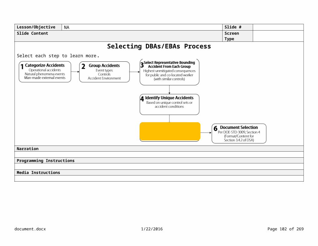
Lesson/Objective Identify the requirements for documenting an accident analysis. Slide #Slide Content Screen Type
Types of Physical MaterialSelect each type of material to learn more.
Non condensable Gas
All materials in the gaseous state can be transported and inhaled.
In DOE nonreactor nuclear facilities, radionuclides in the form of noncondensible gases are only found in a few circumstances: As stored tritium Encased in a stored spent fuel matrix Generated by physical or chemical reaction Generated by inadvertent nuclear criticalities
Vapor
All materials in the gaseous state can be transported and inhaled.
Vapors (materials in gaseous form due to local conditions) may result from two phenomena: Vapors generated from chemical reactions that generate a volatile compound such as halogens in an oxidizing, acidic
environment Vapors that are generated when the local temperature exceeds the boiling point of the element or compound (e.g.,
evaporation of water)
Liquid
In order for a liquid to be made airborne, in most realistic situations, the bulk liquid must be subdivided into particles/droplets small enough to be entrained in the local airflow.
DOE-HDBK-3010 describes mechanisms for two types of liquids (aqueous solutions and organic combustible solvents) that can become airborne. For example, thermal stress, explosive release, free-fall spills, and aerodynamic entrainment can result in airborne release of liquids.
Metal (Solid)
Most metals react with oxygen in some fashion, with some reactions occurring at room temperatures.
At low temperatures, the reaction rates may be so slow that the oxidation is not readily recognized, or a protective oxide film may form that limits/reduces additional oxidation.
Many metals generate heat from the oxidation reaction. Metals that attain a self-sustaining reaction at ambient temperature are called pyrophoric. Some nuclear metals (such as uranium and plutonium) can achieve a self-sustaining reaction at elevated temperature dependent upon surface-to-volume ratio and heat transfer conditions.
Nonmetallic or Composite Solid
Examples of the types of solids in nonreactor facilities (other than simple metals or powders) are aggregates such as: Concrete/cement and limestone/sandstone Glasses such as vitrified high-level waste and products of slagging pyrolosis Spent nuclear fuel, including clad, irradiated, and compacted ceramic oxide
Powder (Solid) For low-energy stresses, powders do not tend to significantly fragment.
document.docx 1/22/2016 Page 102 of 204

For high-energy stresses, the size fraction of powders of concern have relaxation times on the order of fractions of a millisecond, and thus do not tend to present themselves for fragmentation. Therefore, the amount of respirable material assumed airborne (using DOE-HDBK-3010) should not exceed the amount of respirable material originally present in the source MAR, if that value is known.
Narration<Bob> Before we can identify the accident stresses and resulting forces, we need to examine the most common forms of physical material affected by accidents. Accident stresses are unique to the physical form of the material. For example, liquids and powders will react significantly different to different types of stressors. Take a moment to examine the most common types of material affected by accidents. For additional information, refer to DOE-HDBK-3010. Programming InstructionsAdd DOE-HDBK-3010 icon to lower right corner.
When learner clicks on “pyrolosis” show definition: “Pyrolysis is a thermochemical decomposition of organic material at elevated temperatures in the absence of oxygen (or any halogen). Pyrolysis is most commonly observed in organic materials exposed to high temperatures (such as charcoal, activated carbon, and methanol).” Media Instructionssba130_01_03_09.mp3
document.docx 1/22/2016 Page 103 of 204

Lesson/Objective Identify the requirements for documenting an accident analysis. Slide #Slide Content Screen Type
Identifying Accident Stresses and Resulting ForcesSelect each accident stressor to learn more.
Explosive
Explosions can contribute to the airborne release of radiological materials directly through entrainment into gases expelled from the explosion and/or the pressure wave, or by mechanical impact from missiles produced by the explosions (fragmentation).
Shock waves are supersonic pressure waves (pulses) that can transmit an impulse to materials and the surrounding structures resulting in shattering of solid items.
Blast effects are typically subsonic and involve material entrained in the gas flow. Blast effects are often more damaging. Blast effects are not subject to the same reflection/amplification phenomena as shock waves because they have significant momentum and inertia. The gas expanding from the explosion zone carries material from the explosion site. If the explosion is adjacent to the MAR, then blast effects can cause damage above and beyond the initial impulse loading. Some explosive reactions may be followed by chemical reactions, material vaporization, or fires that lead to substantial gas flows following the explosive event. These gas flows may also entrain material.
Deflagrations do not involve shock, but can simulate blast effects. Under proper conditions (e.g., confinement, structural features that enhance turbulence), deflagrations can transition to detonations and produce shock waves.
For additional information on explosive stresses, refer to Section 4.3 of DOE-HDBK-xxxx.
Thermal
Thermal stresses generate heat and combustion gases that may destroy/stress the radioactive material and/or the substrate upon which radioactive materials may be deposited, compromise barriers, and/or pressurize containers/enclosure that may lead to the airborne release of contained radioactive materials.
The mass flux of vapors from the reacting surfaces suspend material in air. This material is then entrained in general convective currents that provide transport for particulate materials.
Mechanical
Mechanical stresses include spills and impacts.
Puncture-Perforation Puncture-perforation of a container or confinement can release materials in a number of ways.
For the release of a volatile material, evaporation is the dominant mechanism. Some solids (e.g., phenol) may vaporize/sublime on release from perforated containers. Materials that are flammable gases or have combustible vapors can be vented and, in the
presence of an ignition source, result in secondary fires. Solutions with non-volatile solvents and powder may vent if the volume is pressurized. Free-fall spill/release of a solid may be followed by a period of evaporation or even
sublimation for volatile solids.
The release and free-fall of liquids and powders (as a result of perforation) can result in suspension from shear stress at the air-material interface.
document.docx 1/22/2016 Page 104 of 204

Crush-Impact This phenomenon imposes force on the surface of the material impacted and can fragment both solids (e.g., brittle fracture and displacement of powders) and liquids (e.g., splashing and droplet formation by displacement and shear).
Shock-Vibration If the surface is not fragmented, particles lying on the surface (e.g., surface contamination and corrosion products) can be jarred from the surface and suspended by vibratory/shock effects.
Abrasion This phenomenon consists of forces applied to the surface layer that induce fragmentation of the surface by mechanical action. Particles generated may be suspended by the mechanical action more efficiently than by aerodynamic forces.
Aerodynamic
Aerodynamic stresses include both entrainment and resuspension.
Entrainment is the entrapment of one substance by another substance. For example, a gas can entrap liquid droplets or solid particulates (such as smoke).
Resuspension refers to the initial suspension of materials from the surface of the particulate mass being affected by the accident stress or air turbulence.
Narration<Bob> Now that we’ve examined some of the physical forms of material that can be affected by accidents, let’s examine some of the accident stresses and resulting forces. Identifying accident stresses is important because it affects airborne respirable fraction (ARF) and respirable fraction (RF) values, which will be used to determine the source term.
DOE-HDBK-XXXX, Table 4-3, provides a cross-reference between the physical form of the material, the accident stressors, and the ARF and RF bounding values. We’ll be determining ARF and RF values in detail later this week, so you might want to take a moment to examine Table 4-3. Programming InstructionsAdd icon of AA Handbook and DOE-HDBK-3010Media Instructionssba130_01_03_10.mp3
document.docx 1/22/2016 Page 105 of 204

Lesson/Objective NA Slide #Slide Content Screen Type
Developing Formal Descriptions of Accident Scenarios
Select each step to learn more.
Narration
Programming Instructions
Media Instructions
document.docx 1/22/2016 Page 106 of 204

Lesson/Objective Identify the requirements for documenting an accident analysis. Slide #Slide Content Screen Type
Identifying Damage to Equipment, Containments, and StructuresSelect each icon to learn more.
Glovebox
During a fire, the weakest point of the glovebox confinement is the gloves. Degradation of the gloves is dependent on the type of glove, and temperature and size of the fire.
If the glovebox uses PMMA shielding (e.g., during heat-source plutonium processing), it is combustible if exposed to direct flame resulting in very high combustion temperatures.
Gloveboxes can also topple during seismic events or be breached by falling debris.
Structural Damage
Failure of structural members can have a major impact on the accident progression. For example, the strength and stiffness of structural steel begins to worsen when heated, leading to possible deformation and failure. Structural, reinforced concrete also may begin to degrade when subjected to extreme temperatures.
Structural damage can also occur during seismic events due to the resulting shock waves and vibration.
Electrical Components
Smoke conductivity or corrosivity can cause sensitive electrical components, such as those associated with alarm systems, to fail.
HEPA Filter
The filter medium in HEPA filters is a very fine diameter glass fiber that softens and melts when heated, making the medium susceptible to heat-induced damage.
Smoke can also impact ventilation system HEPA filters, causing them to clog.
There are two main failure mechanisms for HEPA filter failure: plugging and blowout/media failure.
Plugging occurs when the filter media becomes saturated with particles, preventing adequate airflow. In the case of plugging, the fire generates hot gases, which pushes smoke and contamination outward in the absence of adequate HEPA filter flows.
Blowout/media failure occurs when holes or other openings in the media occur, which allows particulate matter to pass through the HEPA filter. Both of these mechanisms are important, since they both create unfiltered leakage paths, which contribute to the amount of released material.
With HEPA media failure, the ventilation system flows are no longer effectively filtered. Filter clogging occurs before blowout/media failure, and therefore, has been used to determine when loss of confinement occurs.
document.docx 1/22/2016 Page 107 of 204

Narration<Bob> We also need to identify the damage to equipment, containments, and structures for each accident scenario. Remember to consider the damage during subsequent events in addition to the initiating event. These are examples of types of damage to consider during the analysis.Programming Instructions
Media Instructionssba130_01_03_11.mp3
document.docx 1/22/2016 Page 108 of 204

Lesson/Objective NA Slide #Slide Content Screen Type
Developing Formal Descriptions of Accident Scenarios
Select each step to learn more.
Narration
Programming Instructions
Media Instructions
document.docx 1/22/2016 Page 109 of 204

Lesson/Objective Identify the requirements for documenting an accident analysis. Slide #Slide Content Screen Type
Documenting Scenario Development Knowledge CheckWhich of the following are requirements for documenting scenario development (see Section 4 of DOE-STD-3009 for Section 3.4.3.X.1 of the DSA)? Select the appropriate checkboxes.
Operational DBA/EBA
NPHDBA/EBA
External Event
DBA/EBASummarize the load factors, return periods, amplification factors for a facility, and similar variables that characterize the phenomenon
Summarize the magnitude of the energy release and describe the physical conditions (such as temperature or pressures) relevant to accident progression
Summarize the facility and equipment responses to loads or environmental conditions Document the rationale for the unmitigated likelihood assignment used in the hazard evaluation
Narration<Bob> The progression of the accident, or scenario development, is documented in the DSA. The contractor must describe the progression of the accident by linking the initiating event with the preventive and mitigative controls and other contributing phenomena. Some of the requirements for documenting the scenario development are dependent on the type of accident.Feedback InstructionsTry again. Take another look at Section 4 of DOE-STD-3009 for Section 3.4.3.X.1 of the DSA. Incorrect. <Show visual feedback>Correct. Media InstructionsAdd icon for DOE-STD-3009sba130_01_03_12.mp3
document.docx 1/22/2016 Page 110 of 204
Submit

Lesson/Objective Outline the process for performing an accident analysis. Slide #Slide Content Screen Type Drag and drop
Process Knowledge CheckDrag and drop each label to the appropriate step.
Narration
Programming InstructionsTry again. Incorrect. <Show visual feedback>That’s correct.Media Instructions
document.docx 1/22/2016 Page 111 of 204
Determine Inputs, Assumptions and Initial Conditions
Determine Accident Phenomena
Identify Accident Progression
Identify Accident Stresses and
Resulting Forces
Identify Damage to Effected Equipment Containments, and
Structures
Document Scenario Development
Submit

Lesson/Objective Identify the requirements for documenting an accident analysis. Slide #Slide Content Screen Type Video
Scenario Development – Furnace Malfunction ScenarioHA-ID
# Type Scenario Initiating Event or
CauseDescription Likelihood Consequence Risk Notes
P CW W P CW W
FF-04 Operational Accident/Fire
Furnace temperature excursion, combustibles adjacent to furnace, fire inside glovebox, and glovebox breach
Furnace malfunction Uncontrolled U H H H I I I MAR – 9,000 g of Pu
Controlled EU L L M IV IV IIIBuilding confinement ventilation system
Building structural integrity Combustible loading program Emergency Preparedness Program
Building and glovebox fire suppression system
Glovebox design integrity and confinment
High-temp limiting switch
Narration<Bob> Before we move on, let’s take a look at the scenario development for the furnace malfunction scenario.
In this scenario, the furnace controller in the glovebox malfunctions causing 4,500 g of a pyrophoric metal to become molten and oxidize. Approximately 5 pounds of combustibles in the glovebox ignite from the heat released by the furnace and the metal. The fire reaches 212 degrees Fahrenheit, which is a sufficient temperature to burn the gloves, the weakest point of the glovebox confinement.
The glovebox atmosphere quickly heats to 1,000 ºF, and then stabilizes at 1,600 ºF to 1,800 ºF. After the fire breaches the gloves, the room air increases from 70 °F to 80 °F.
The room temperature increases through two heat-transfer mechanisms. First, heat transfers through the hot walls of the glovebox. Second, hot gases move into the room through the failed glove ports.
If the ventilation system is operating at the time of the release, the released aerosol is carried to the HEPA filters, where it becomes trapped.
If the ventilation system is off or fails, the glovebox atmosphere eventually equilibrates with the room atmosphere, raising its temperatures approximately 10 °F. Without exhaust ventilation, most combustion gases pass from the glovebox to the room.
As workers evacuate the building, the doors are propped open causing loss of confinement integrity that allows the release of material into the
document.docx 1/22/2016 Page 112 of 204

atmosphere.Programming Instructionssba130_01_03_13_01.mp3sba130_01_03_13_02.mp3sba130_01_03_13_03.mp3sba130_01_03_13_04.mp3sba130_01_03_13_05.mp3sba130_01_03_13_06.mp3sba130_01_03_13_07.mp3Media Instructions
Furnace controller in glovebox malfunctions
1. Add label “Furnace malfunctions causing 4,500 g of pyrophoric metal to become molten and oxidize”
2. Show molten metal and combustibles (cleaning wipes, plastic, cellulose items) in glovebox
3. Add label “5 lb of combustibles (cellulose) ignite”
Fire breaches gloves
1. Add label “Fire reaches 212 °F and gloves fail”
2. Show breach in gloves3. Add label “Glovebox atmosphere
heats to 1000 °F and then stabilizes at 1600 °F to 1800 °F”
DO NOT SHOW DRUM
document.docx 1/22/2016 Page 113 of 204

Fire spreads to room
1. Add label “After glove breach, room air increases from 70 °F to 80 °F”
2. Show label “Heat transfer through hot walls of glovebox”
3. Show label “Hot gases move into room through failed glove ports”
DO NOT SHOW DRUM
Ventilation system fails
1. Add label “If ventilation system fails, combustion gases pass from the glovebox to the room”
2. Show smoke filling room Confinement system fails
1. Show open doors to room and hallway
2. Show smoke escaping to outside3. Add label “Loss of containment
allows release of material into the atmosphere”
document.docx 1/22/2016 Page 114 of 204

Lesson/Objective Identify the requirements for documenting an accident analysis.Outline the process for performing an accident analysis.
Slide #
Slide Content Screen TypeKey Points
1. Determine inputs, assumptions, and initial conditions MAR values used during the accident analysis must be consistent with the values noted in the hazard identification and evaluation. The MAR value must be bounding with respect to each accident being evaluated. Initial conditions and assumptions shall be protected at a level commensurate with their importance.
2. Determine accident phenomena Phenomenological modeling involves performing calculations to understand the dynamics of the accident conditions and to demonstrate the
effectiveness of either preventive or mitigative safety controls. Phenomenological modeling helps us understand the routes by which radioactive material is released and the processes involved in the transport and
movement of materials released to the atmosphere.
3. Identify accident progression Link the initiating event with the preventive and mitigative controls and other contributing phenomena. Each response, action, or indication required to initiate action is considered relevant to the scenario progression.
4. Identify accident stresses and resulting forces Accident stresses are unique to the physical form of the material. The physical form of the material and accident stresses are used to determine the ARF/RF values when calculating the source term.
5. Identify damage to effected equipment, containments, and structures Consider the damage during the initial event, as well as subsequent events.
6. Document scenario development Section 3.4.3.X.1 of the DSA describes the progression of the accident. Refer to Section 4 of DOE-STD-3009 for the requirements for documenting the scenario development.
Narration
Programming Instructions
Media Instructions
document.docx 1/22/2016 Page 115 of 204

Lesson/Objective NA Slide #Slide Content Screen Type Menu
Menu
Purpose and Scope
Selecting DBAs/EBAs
Developing Formal Descriptions of Accident Scenarios
Calculating Radiological Source Term
Calculating Radiological Dose
Comparing Consequence Estimates to the EG and/or CW Threshold
Narration
Programming Instructions
Media Instructions
document.docx 1/22/2016 Page 116 of 204

Lesson/Objective Calculate the source term based on the derived inputs. Slide #Slide Content Screen Type
Calculating Radiological Source Term and DoseID # Type Scenario Initiating Event or
CauseDescription Likelihood Consequence Risk Notes
P CW W P CW W
FF-04 Operational Accident/Fire
Furnace temperature excursion, combustibles adjacent to furnace, fire inside glovebox, and glovebox breach
Furnace malfunction Uncontrolled U H H H I I I MAR – 9,000 g of Pu
Controlled EU L L M IV IV IIIBuilding confinement ventilation system
Building structural integrity Combustible loading program Emergency Preparedness Program
Building and glovebox fire suppression system
Glovebox design integrity and confinement
High-temp limiting switch
Narration
document.docx 1/22/2016 Page 117 of 204

<Bob> During the hazard evaluation, we estimated the radiological consequences to the worker, co-located worker, and the public using qualitative methods. <Highlight consequence estimates from Hazard Evaluation Table> During the accident analysis, we’re going to calculate the radiological consequences for the co-located worker and the public using quantitative methods.
Calculating the radiological consequences is a two-step process, which involves calculating the source term and then the radiological dose. <Show formulas>Programming Instructions
Media Instructionssba130_01_04_01.mp3
document.docx 1/22/2016 Page 118 of 204

Lesson/Objective Calculate the source term based on the derived inputs. Slide #Slide Content Screen Type
Calculating Radiological Source Term and Dose Control MAR DR ARF RF LPF ST X/Q BR DCF Dose to
Source Term Ratio (DSTR)
Dose
CW P CW P CW P CW PUnmitigated 9,000 g 1.0 1E-2 1.0 1.0 90 g 3.5 x 10-
35.74E-
053.3E-4 m3/s
8.3E-06 rem/g
1.6E-05rem/g
xxx xxx xxx xxx
ID # Type Scenario Initiating Event or Cause
Description Likelihood Consequence Risk NotesP CW W P CW W
FF-04 Operational Accident/Fire
Furnace temperature excursion, combustibles adjacent to furnace, fire inside glovebox, and glovebox breach
Furnace malfunction Uncontrolled U H H H I I I MAR – 9,000 g of Pu
Controlled EU L L M IV IV IIIBuilding confinement ventilation system
Building structural integrity Combustible loading program Emergency Preparedness Program
Building and glovebox fire suppression system
Glovebox design integrity and confinment
High-temp limiting switch
Narration<Bob> Using the calculated unmitigated source term <highlight ST>, we can calculate the unmitigated radiological dose consequence. <highlight dose> If the unmitigated radiological dose consequence exceeds or challenges the evaluation guideline for the public, and/or exceeds the threshold for the co-located worker, then mitigated analysis is required. <show Table 1 with EG and CW threshold highlighted>
A mitigated analysis is required if the credited preventive controls identified in the hazard evaluation do not eliminate the hazard or terminate the accident. <highlight controls in hazard evaluation table>
The mitigated analysis becomes an iterative process in that the source term and radiological dose are re-calculated for each mitigative control credited until the consequences do not challenge or exceed the evaluation guideline for the public and/or exceed the threshold for the co-located worker. <Show AA table with re-calculation for ST and dose>
document.docx 1/22/2016 Page 119 of 204

Programming Instructions
Media Instructionssba130_01_04_02.mp3
document.docx 1/22/2016 Page 120 of 204

Lesson/Objective Calculate the source term based on the derived inputs. Slide #Slide Content Screen Type
Chemical Hazards
SS designation of controls for protection of the public from chemical releases shall be based on a peak 15 minute time-weighted average air concentration, measured at the receptor location, that exceeds PAC-2.
SS designation for protection of co-located workers from chemical releases shall be based on a peak 15 minute time-weighted average air concentration at the receptor location that exceeds PAC-3.
Narration<Bob> During the hazard identification process, we excluded, or screened out, the chemical hazards using the criteria in Appendix A.2 of DOE-STD-3009.
However, if a facility has chemical hazards that are not screened out and chemical scenario consequences exceed the criteria for the public and co-located worker as provided in Section 3.3.2, then the contractor must calculate the chemical source term and consequence using the guidance in Section 3.2.4.3 of DOE-STD-3009.
We’re going to focus on calculating the radiological source term and dose. So let’s get started by calculating the unmitigated source term.Programming Instructions
Media Instructionssba130_01_04_03.mp3
document.docx 1/22/2016 Page 121 of 204

Lesson/Objective Calculate the source term based on the derived inputs. Slide #Slide Content Screen Type
Calculating Source Term Activity
Drag and drop the label to the correct definition.
Narration<Bob> During the hazard evaluation, we examined the steps for determining the radiological source term. The source term is the amount of material released to the environment as a respirable aerosol. It’s calculated using the five-factor formula described in DOE-HDBK-3010. Let’s see how much you remember about calculating the radiological source term.
<Bob Feedback> The radiological source term is typically calculated as the product of five factors: (1) the MAR; (2) the damage ratio (or DR); (3) the airborne release fraction (or ARF); (4) the respirable fraction (or RF); and (5) the leakpath factor (or LPF). Programming InstructionsShow one question at a time. Question 1 (MAR) – What is the term for the bounding quantity of radioactive material that is available to be acted upon by a given physical stress from an accident? Question 2 (DR) – What is the fraction of material that is actually affected by the accident-generating conditions? Question 3 (ARF) – What is the coefficient used to estimate the amount of radioactive material that can be suspended in air? Question 4 (RF) – What is the fraction of airborne radioactive particles that can be transported through air and inhaled into the human respiratory system? Question 5 (LPF) – What is the fraction of material that passes through the confinement system?
document.docx 1/22/2016 Page 122 of 204

Question 6 (ST) – What is the amount of radioactive material, in grams or curies, that is released to the air? Feedback InstructionsImmediate visual feedbackMedia Instructionssba130_01_04_04.mp3sba130_01_04_05.mp3
document.docx 1/22/2016 Page 123 of 204

Lesson/Objective NA Slide #Slide Content Screen Type Submenu
Calculating Radiological Source TermSelect each term to learn more.
Narration
Programming Instructions
Media Instructions
document.docx 1/22/2016 Page 124 of 204

Lesson/Objective Calculate the source term based on the derived inputs. Slide #Slide Content Screen Type
Determining MAR
“The MAR is the bounding quantity of radioactive material that is available to be acted upon by a given physical stress from a postulated accident. The MAR may be the total inventory in a facility or a portion of this inventory in one location or operation, depending on the event. MAR values used in hazard and accident analysis shall be consistent with the values noted in hazard identification/evaluation, and shall be bounding with respect to each accident being evaluated.” DOE-STD-3009
Narration<Bob> During the accident analysis, it’s important to remember that the MAR may be different for different accident scenarios. It’s only necessary to define the material in the discrete physical locations that are exposed to a given stress. For example, a loss of containment such as a spill may involve only one glovebox.<Highlight glovebox> However, a fire may threaten the MAR in several gloveboxes, a room, or all of the material in a building. <Highlight multiple gloveboxes, room, building in sync> The MAR value identified in the accident analysis should be consistent with the values documented during the hazard identification and hazard evaluation.Programming Instructions
Media Instructionssba130_01_04_06.mp3
document.docx 1/22/2016 Page 125 of 204

Lesson/Objective Calculate the source term based on the derived inputs. Slide #Slide Content Screen Type
MAR Knowledge CheckWhat is the MAR for this accident scenario? Enter the number of grams in the bottom table.
HA-ID #
Type Scenario Initiating Event or Cause Description Likelihood Consequence RiskP CW W P CW W
HA-## Operational Accident/Fire
Furnace temperature excursion, combustibles adjacent to furnace, fire inside glovebox, and glovebox breach
Furnace malfunction Uncontrolled U H H H I I I
Control MAR ARF RF DR LPF ST
Unmitigated 9,000 g Narration<Bob> Earlier today, we examined the accident scenario involving the glovebox fire started by a malfunctioning furnace. The malfunction caused 4,500 g of a pyrophoric plutonium metal to become molten and oxidize. During a single run, between 2,000 to 4,000 g of plutonium is typically processed. However, the specific administrative control is set at 9,000 g of plutonium. What is the MAR for the furnace malfunction scenario?Feedback InstructionsTry again. Remember that the MAR should be conservatively estimated. Incorrect. Although 2,000 to 4,000 g of plutonium is typically processed during a single run in one glovebox, the administrative control is set at 9,000 g. Therefore, the MAR should be conservatively estimated at 9,000 g of plutonium. That’s correct. The MAR should be conservatively estimated at 9,000 g of plutonium.Media Instructionssba130_01_04_07.mp3
document.docx 1/22/2016 Page 126 of 204

Lesson/Objective NA Slide #Slide Content Screen Type
Calculating Radiological Source Term
Narration
Programming Instructions
Media Instructions
document.docx 1/22/2016 Page 127 of 204

Lesson/Objective Calculate the source term based on the derived inputs. Slide #Slide Content Screen Type
Determining DR ActivityEnter the damage ratio (decimal) for each situation in the blank.
Small fire impacts one of four shelves of containers
DR = _______
Answer: DR = 1/4 (or 0.25)
Large fire impacts all four shelves in the vault
DR = _______
Answer: DR = 1.0
Falling crane crushes 15 drums out of 60 drums
DR = _______Answer: DR = 15/60 (or 0.25)
Narration<Bob> The DR is the fraction of material that is actually affected by the accident-generating conditions. According to DOE-STD-3009, a DR of 1.0 shall be used for the unmitigated analysis unless there is an applicable standard or technical basis for a different value. For example, DOE-STD-5506 provides damage ratios for transuranic waste facilities.
What is the DR for each of these examples? Feedback InstructionsImmediate visual feedbackMedia Instructionssba130_01_04_08.mp3
document.docx 1/22/2016 Page 128 of 204
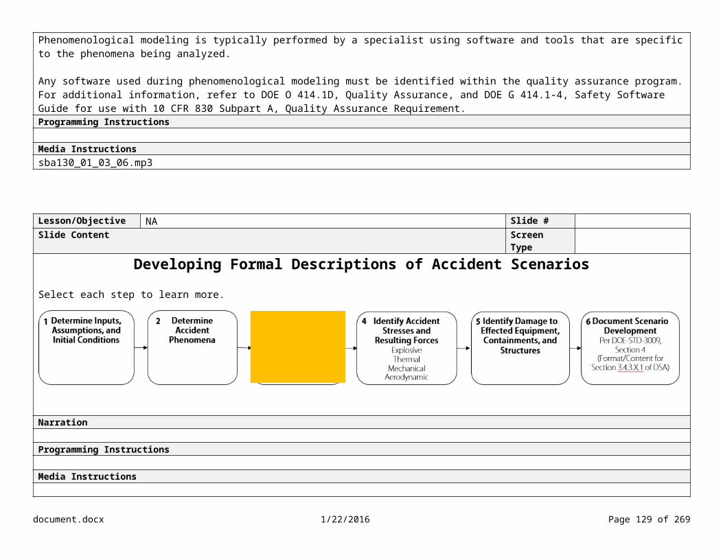
Lesson/Objective Calculate the source term based on the derived inputs. Slide #Slide Content Screen Type
Determining DR at a Plutonium Recovery FacilitySelect each marker to learn more.
Narration<Bob> Let’s look at another example at a plutonium recovery facility. Programming Instructions
Media Instructions
sba130_01_04_09.mp3
document.docx 1/22/2016 Page 129 of 204

Lesson/Objective Calculate the source term based on the derived inputs. Slide #Slide Content Screen Type
Determining DR Knowledge Check
See questions below
Narration<Bob> According to a seismic study, the south wall at this facility is vulnerable to a seismic event. The affected equipment includes half of the dissolution glovebox and the final glovebox (#4) in the fuel fabrication line. The study indicates all other gloveboxes and major equipment have sufficient margin to survive the seismic stress. What is the DR for each situation? Question/Feedback InstructionsShow questions one at a time.
Question Answer FeedbackWhat is the DR for the Dissolution Area?DR = _____
1.0 Try again. How much MAR is contained in the Dissolution glovebox? What portion of the MAR is impacted by the seismic event? Incorrect. The MAR for the Dissolution glovebox is 3,000 g. The seismic event impacts all the MAR; therefore, the DR is 1.0.
document.docx 1/22/2016 Page 130 of 204

Correct. The seismic event impacts all the MAR; therefore, the DR is 1.0.
What is the DR for the Purification Area? Assume the gloveboxes remain intact.
Ion Exchange Glovebox DR = ______Precipitation Glovebox DR = _______
00
Try again. What portion of the MAR is impacted by the seismic event? Incorrect. Since the gloveboxes remain intact, the DR for both gloveboxes is 0. Correct. Since the gloveboxes remain intact, the DR for both gloveboxes is 0.
Which of the following assumptions would you make concerning the Fuel Fabricator room?
Effects of the seismic event only impact glovebox #4 Effects of the seismic event impact glovebox #3 and #4 Although the accident stress is centered on glovebox #4, the effects of the seismic shock also impact glovebox #1, #2, and #3
Try again. Remember that you need to consider the effects of the seismic shock wave on the gloveboxes in the fuel fabrication line. Incorrect. In addition to the initial accident stress from the seismic event on glovebox #4, you need to assume that the resulting seismic shock could impact the remaining gloveboxes in the line.Correct. The effects of the seismic shock could impact all of the gloveboxes in the Fuel Fabricator room.
What is the DR for the Fuel Fabricator room? Glovebox 1 and 2 DR = _______Glovebox 3 and 4 DR = _______
0.50.5
Try again. The overall MAR for the room is 6 kg of plutonium oxide. What fraction of the MAR is contained in glovebox #3 and #4? What fraction of the MAR is contained in glovebox #1 and #2? Incorrect. The DR for the oxide power in glovebox #3 and #4 is 0.5 (3,000/6,000). The DR for glovebox #1 and #2 is also 0.5 (based on a conservative estimate since the seismic shock could cause a small release stress). Correct. The DR is 0.5 for glovebox #1 and #2, as well as glovebox #3 and #4.
Media Instructionssba130_01_04_10.mp3
document.docx 1/22/2016 Page 131 of 204

Lesson/Objective Calculate the source term based on the derived inputs. Slide #Slide Content Screen Type
Determining DR for Furnace Malfunction Knowledge Check What is the DR for this accident scenario? Enter the value in the bottom table.
HA-ID #
Type Scenario Initiating Event or Cause Description Likelihood Consequence RiskP CW W P CW W
HA-## Operational Accident/Fire
Furnace temperature excursion, combustibles adjacent to furnace, fire inside glovebox, and glovebox breach
Furnace malfunction Uncontrolled U H H H I I I
Control MAR DR ARF RF LPF ST
Unmitigated 9,000 1.0
Narration
<Bob> Let’s take another look at the furnace malfunction accident scenario. What is the DR?Feedback InstructionsTry again. If the fire affected all material in the glovebox, what is the DR? Incorrect. The fire affected all the material in the glovebox; therefore, the DR is 1.0.Correct. The fire affected all the material in the glovebox; therefore, the DR is 1.0. Media Instructionssba130_01_04_11.mp3
document.docx 1/22/2016 Page 132 of 204

Lesson/Objective NA Slide #Slide Content Screen Type
Calculating Radiological Source Term
Narration
Programming Instructions
Media Instructions
document.docx 1/22/2016 Page 133 of 204

Lesson/Objective Calculate the source term based on the derived inputs. Slide #Slide Content Screen Type
Determining ARF/RF
Narration<Bob> According to DOE-HDBK-3010, ARF is the coefficient used to estimate the amount of a radioactive material suspended in air as an aerosol and thus available for transport due to a physical stresses from a specific accident. The airborne pathway is normally the exposure mechanism evaluated, because it is the primary method by which exposures at a distance from the point of release can occur. The ARF value is selected based on type and level of stressor impacting the MAR and the physical form of the MAR.
According to DOE-STD-3009, RF is the fraction of airborne radionuclide particles that can be transported through air and inhaled into the human respiratory system. The RF is commonly assumed to include particles of 10-μm (microns) aerodynamic equivalent diameter (or AED) and less. Particles greater than 10 microns AED are less likely to be transported into the lung, and therefore are not as effective in imparting a radiation dose to the body.Programming Instructions
Media Instructionssba130_01_04_12.mp3
document.docx 1/22/2016 Page 134 of 204
The RF is the fraction of airborne radionuclide particles that can be transported through air and inhaled into the human respiratory system. DOE-STD-3009
“The ARF is the coefficient used to estimate the amount of a radioactive material suspended in air as an aerosol and thus available for transport due to a physical stresses from a specific accident.” DOE-HDBK-3010

Lesson/Objective Calculate the source term based on the derived inputs. Slide #Slide Content Screen Type
Determining ARFSelect each document for an enlarged view.
document.docx 1/22/2016 Page 135 of 204
Locate the physical material (e.g., liquid, powder, metal, etc.).
Locate the accident stressor for the scenario (e.g., explosion, thermal, mechanical/spill, aerodynamic).
Locate the conditions that best fit the accident scenario (e.g., fall distance < 3m).
Locate the bounding ARF/RF value.
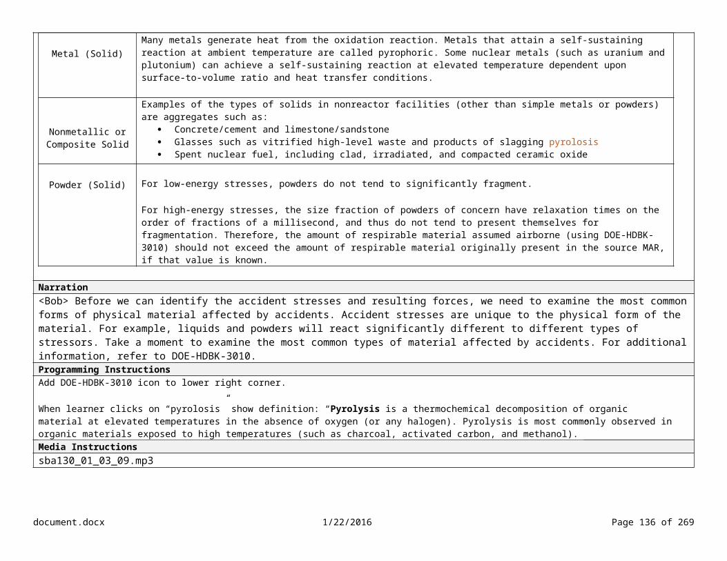
Narration<Bob> DOE-HDBK-3010 lists the bounding estimates for radionuclide ARFs and RFs for a wide variety of MAR and release phenomena. DOE-HDBK-xxxx contains a summary of the bounding values found in DOE-HDBK-3010. According to DOE-STD-3009, the bounding estimates shall be used unless a different value is provided in an applicable standard or is otherwise technically justified. Take a moment to examine how the ARF and RF value is determined.Programming Instructions
Media InstructionsUse lightboxessba130_01_04_13.mp3
document.docx 1/22/2016 Page 136 of 204
Technical Support Level (TSL)
The ARF/RF values are derived from an analysis of experimental data. The number in this column represents the following: 1 – Supported by experimental data from more than one independent source of the stated range with experimental support for particle generation mechanism2 – Experimental support over the stated range 3 – Single experimental datum or inferred from other studies

Lesson/Objective Calculate the source term based on the derived inputs. Slide #Slide Content Screen Type
Determining ARF/RF Knowledge Check (1 of 2)What is the stress being imposed on any powder contained in the gloveboxes in the fuel fabrication line?
Explosive Thermal Mechanical Aerodynamic entrainment
Narration<Bob> Let’s take another look at the fuel fabrication line for the plutonium recovery facility during a seismic event. For this scenario, assume that the structural collapse does not occur and all four gloveboxes in the fuel fabrication line remain intact. That is, they remain upright in a largely undamaged state. What is the stress being imposed on the powder?Programming Instructions Feedback InstructionsTry again. Although structural collapse does not occur and the gloveboxes remain intact, what stressor could result from the associated seismic vibration? Incorrect. Even though structural collapse does not occur and the gloveboxes remain intact, they will experience transitory movement of structural members and the associated seismic vibration. This force is sufficient to produce a small amount of aerosolization for the fragmented powders. This is a mechanical stress. Correct. The transitory movement of the structural members and associated seismic vibration from the event is a mechanical stress.Media Instructionssba130_01_04_14.mp3
document.docx 1/22/2016 Page 137 of 204

Lesson/Objective Calculate the source term based on the derived inputs. Slide #Slide Content Screen Type
Determining ARF/RF Knowledge Check (2 of 2)
Using Table 5-1 in DOE-HDBK-xxxx, what are the ARF and RF values for shock/vibration of bulk powders (for a mechanical stress)? Enter your answers in the blanks.
ARF = ___1E-3____
RF = __0.1_____
Feedback
Narration
Programming Instructions Feedback InstructionsTry again. Take another look at the section for Mechanical Stress for a bulk powder in Table 5-1 from DOE-HDBK-xxxx. Incorrect. The ARF value is 1E-3 and the RF value is 0.1. Correct. The ARF value is 1E-3 and the RF value is 0.1.Media InstructionsFor feedback, show screen shot of table 5-1 with correct row highlighted.
document.docx 1/22/2016 Page 138 of 204

Lesson/Objective Calculate the source term based on the derived inputs. Slide #Slide Content Screen Type
Determining ARF/RF Example
Narration<Bob> Let’s examine the scenario where structural collapse does occur and is sufficiently severe to collapse all four gloveboxes in the fuel fabrication line. We need to break the scenario into a sequence of distinct events. First, a glovebox may tip over or slump down due to the legs collapsing. Second, a glovebox may be impacted by debris. The windows may break allowing the contents to spill out. Both of these scenarios present the possibility of debris impacting the powder.
During the previous scenario, we used the ARF/RF values for a bulk powder packaged in a container. However, for this scenario, there are different stresses imposed on the powder in the glovebox. Although still a mechanical stress, we now have two possible situations: free-fall spill of a powder and powder that is impacted by falling debris. Since both situations could occur during the same scenario, we need to calculate the ARF and RF to account for both events.Programming Instructions Feedback Instructions
Media Instructionssba130_01_04_15.mp3
document.docx 1/22/2016 Page 139 of 204

Lesson/Objective Calculate the source term based on the derived inputs. Slide #Slide Content Screen Type
Determining ARF/RF Knowledge Check Using Table 5-1 in DOE-HDBK-xxxx, what are the AFR/RF values for a free-fall spill of powder and falling debris impacting the powder? Enter your answers in the table below.
Event ARF RF ARF * RF
Powder, spill distance < 3 m 2E-3 0.3 6E-4
Powder, shock impact due to falling debris 1E-2 0.2 2E-3
Cumulative Total 2.6E-3
Feedback
Narration
Programming InstructionsLearner enters ARF/RF values; program calculates the cumulative totalFeedback InstructionsTry again. Take another look at Table 5-1 in DOE-HDBK-xxxx. Incorrect. <Show correct answers> The ARF value for a free-fall spill of a powder at less than 3 meters is 2E-3. The RF value is 0.3. The ARF value for a loose powder that falls and is impacted by debris is 1E-2. The RF value is 0.2. If both events occur, then the cumulative ARF/RF could be as high as 2.6E-3 (6E-4 + 2E-3). Correct. The ARF value for a free-fall spill of a powder at less than 3 meters is 2E-3. The RF value is 0.3. The ARF value for a loose powder that falls and is impacted by debris is 1E-2. The RF value is 0.2. If both events occur, then the cumulative ARF/RF could be as high as 2.6E-3 (6E-4 + 2E-3).Media Instructions
document.docx 1/22/2016 Page 140 of 204

Lesson/Objective Calculate the source term based on the derived inputs. Slide #Slide Content Screen Type
Determining ARF/RF for Furnace Malfunction
ID # Type Scenario Initiating Event or Cause Description Likelihood Consequence RiskP CW W P CW W
F-04 Operational Accident/Fire
Furnace temperature excursion, combustibles adjacent to furnace, fire inside glovebox, and glovebox breach
Furnace malfunction Uncontrolled U H H H I I I
Control MAR DR ARF RF LPFUnmitigated 9,000 1.0 1E-2 1.0
Narration<Bob> Let’s determine ARF and RF values for the furnace malfunction accident scenario. The malfunctioning furnace control would maintain a very high temperature, which might cause the metal surface to roil. As a result, the airborne release would be greater. For the purposes of this analysis, a bounding ARF value of 1E-2 was selected. In this instance, and RF value is not provided. According to DOE-HDBK-3010, when an RF value is not provided, we should assume a value of 1.0 for conservatism.Programming Instructionssba130_01_04_16.mp3Feedback Instructions
NoteNote: Page 1-6 of DOE-HDBK-3010, Volume 1, paragraph: “Measured experimental data for RFs are much more limited but are from the same general sources used for the ARFs…In some cases, where significant uncertainty may exist, RFs are arbitrarily set to a value of 1.0 for conservatism.” When an RF value is not provided in Table 5-1, assume a value of 1.0 for conservatism.
document.docx 1/22/2016 Page 141 of 204

Lesson/Objective NA Slide #Slide Content Screen Type
Calculating Radiological Source Term
Narration
Programming Instructions
Media Instructions
document.docx 1/22/2016 Page 142 of 204

Lesson/Objective Calculate the source term based on the derived inputs. Slide #Slide Content Screen Type
Determining the Leakpath Factor“The LPF is the fraction of material that passes through some confinement deposition or filtration mechanism.” DOE-STD-3009
Narration<Bob> According to DOE-STD-3009, the leakpath factor (or LPF) is the fraction of material that passes through some confinement deposition or filtration mechanism. The LPF value used in the five-factor formula is the total fraction of respirable airborne material released during the accident that escapes from the building to the environment. It is of interest in accident analysis because it has the potential to reduce the initial source term before it exits the facility, producing a much smaller release to the external environment.
For the unmitigated analysis, assume the aerosolized material exits to the atmosphere without retention. Per DOE-STD-3009, for the purposes of the unmitigated analysis, the LPF shall be set to 1.0.
For the mitigated analysis, several leakpaths may be associated with a specific accident, such as the fraction passing from a glovebox, the fraction passing from a room, or the fraction passing through a leaking door. When determining the leakpath, you also need to consider the location of the source within the building, the external wind conditions, and whether the interior and exterior doors are open or closed. We’ll walk through the process of calculating the LPF again when we select controls during the mitigated analysis. Programming Instructions
Media Instructions
document.docx 1/22/2016 Page 143 of 204

sba130_01_04_17.mp3
Lesson/Objective Calculate the source term based on the derived inputs. Slide #Slide Content Screen Type
Determining LPF for Furnace Malfunction Knowledge CheckWhat is the unmitigated LPF for this scenario? Enter the value in the bottom table.
ID # Type Scenario Initiating Event or Cause
Description Likelihood Consequence RiskP CW W P CW W
F-04 Operational Accident/Fire
Furnace temperature excursion, combustibles adjacent to furnace, fire inside glovebox, and glovebox breach
Furnace malfunction
Uncontrolled U H H H I I I
Control MAR DR ARF RF LPF ST
Unmitigated 9,000 1.0 1E-2 1.0 1.0 Narration
Programming Instructions
Feedback InstructionsTry again. For the unmitigated analysis, assume the aerosolized material exits to the atmosphere without retention. Incorrect. For an unmitigated analysis, use a LPF of 1.0. Correct. The LPF for an unmitigated analysis is 1.0. Media Instructions
document.docx 1/22/2016 Page 144 of 204

Lesson/Objective NA Slide #Slide Content Screen Type
Calculating Radiological Source Term
Narration
Programming Instructions
Media Instructions
document.docx 1/22/2016 Page 145 of 204

Lesson/Objective Calculate the source term based on the derived inputs.Identify the requirements for documenting an accident analysis.
Slide #
Slide Content Screen Type
Calculating Radiological Source Term
Calculations shall be made based on technically justified input parameters and underlying assumptions such that the overall consequence calculation is conservative. Conservatism is assured by the selection of bounding accident scenarios, the use of a conservative analysis methodology, and the selection of source term and input parameters that are consistent with that methodology. DOE-STD-3009
MAR * DR * ARF * RF * LPF = ST
Narration<Bob> It looks like we’re ready to calculate the source term. There are few things to remember. The input parameters and underlying assumptions must be technically justified. Also, the overall consequence must be conservatively calculated. This is assured by the selection of bounding accident scenarios, the use of a conservative analysis methodology, and the selection of source term and input parameters that are consistent with the chosen methodology. The basis for determining the source term is to use a combination of parameters on the upper end of any potential uncertainty.
The results of the source term analysis must be documented in Section 3.4.3.X.2 of the DSA. This section identifies the material and energy released through the pathways of concern during the accident, defines the parameters and phenomenological models used to derive the source term, and addresses the characteristics of the release. Ensure that this section of the DSA also presents a discussion of the source term factors described in Section 3.2.4.1 of DOE-STD-3009. Programming InstructionsAdd bullets in sync with narration.Media Instructionssba130_01_04_18.mp3
document.docx 1/22/2016 Page 146 of 204

Lesson/Objective Calculate the source term based on the derived inputs. Slide #Slide Content Screen Type
Determining Source Term Knowledge CheckWhat is the unmitigated source term for this scenario? Enter the value in the table below.
ID # Type Scenario Initiating Event or Cause
Description Likelihood Consequence RiskP CW W P CW W
F-04 Operational Accident/Fire
Furnace temperature excursion, combustibles adjacent to furnace, fire inside glovebox, and glovebox breach
Furnace malfunction Uncontrolled U H H H I I I
Control MAR DR ARF RF LPF ST
Unmitigated 9,000 g 1.0 1E-2 1.0 1.0 90 Narration
Feedback InstructionsTry again. The five-factor formula for calculating the source term is MAR * DR * ARF * RF * LPF. Incorrect. The source term for this scenario is 90 g. Correct. The source term for this scenario is 90 g.Media Instructions
document.docx 1/22/2016 Page 147 of 204

Lesson/Objective Identify the factors that should be considered when calculating source term and dose.
Slide #
Slide Content Screen Type
Calculating Source Term Knowledge CheckWhich of the following should be assumed when calculating the unmitigated source term? Select all that apply.
Assume the aerosolized material exits to the atmosphere without retention and use an LPF of 1.0
Assume an airborne pathway for the exposure mechanism when determining ARF and RF (unless it is not the primary mechanism)
Determine the fraction of material that is actually affected by the accident-generating conditions for the DR
Use the total inventory in a facility or operation when determining the MAR
Narration
Programming Instructions Feedback InstructionsTry again. Incorrect. When calculating the unmitigated source term, assume the aerosolized material exits to the atmosphere without retention and use an LPF of 1.0, assume an airborne pathway, and determine the fraction of material that is actually affected by the accident-generating conditions for the DR. Although the MAR may be the total inventory in a facility or operation, it should be calculated based on the bounding quantity of material that is available to be acted upon by a given physical stress from a postulated accident. Correct. Media Instructions
document.docx 1/22/2016 Page 148 of 204

Lesson/Objective Calculate the source term based on the derived inputs. Slide #Slide Content Screen Type
Key PointsSelect each term to review the key points.
Narration
Programming InstructionsShow key points when learner selects each term.
MARDefine the material in the discrete physical locations that are exposed to a given stress.The material at risk (MAR) value identified in the accident analysis should be consistent with the values documented during the hazard identification and hazard evaluation.DRThe damage ratio (DR) is the fraction of material that is actually affected by the accident-generating conditions.Use a DR of 1.0 unless there is an applicable standard or technical basis for a different value. ARFThe airborne release fraction (ARF) is the coefficient used to estimate the amount of a radioactive material suspended in air as an aerosol and thus available for transport due to physical stresses from a specific accident.Locate the ARF value using DOE-HDBK-3010.RFThe respirable fraction (RF) is the fraction of airborne radionuclide particles that can be transported through air and inhaled into the human respiratory system.Locate the ARF value using DOE-HDBK-3010. LPFThe leakpath factor (LPF) is the fraction of material that passes through some confinement deposition or filtration mechanism.For the unmitigated analysis, assume the aerosolized material exits to the atmosphere without retention and use an LPF of 1.0.STEnsure the input parameters and underlying assumptions are technically justified. Ensure the source term (ST) analysis is documented in Section 3.4.3.X.2 of the DSA (following the guidance in Section 4 of the DOE-STD-3009).Feedback Instructions
Media Instructions
document.docx 1/22/2016 Page 149 of 204

Lesson/Objective NA Slide #Slide Content Screen Type Menu
Menu
Purpose and Scope
Selecting DBAs/EBAs
Developing Formal Descriptions of Accident Scenarios
Calculating Radiological Source Term
Calculating Radiological Dose
Comparing Consequence Estimates to the EG and/or CW Threshold
Narration
Programming Instructions
Media Instructions
document.docx 1/22/2016 Page 150 of 204

Lesson/Objective Calculate the dose consequence based on the derived X (chi)/Q value. Slide #Slide Content Screen Type
Types of Dose Pathways
Narration<Bob> Before we calculate the radiological dose, let’s look at the general modes of exposure.
According to DOE-STD-3009, the dose pathways to be considered include inhalation, groundshine, and direct shine. Direct shine and groundshine from gamma emitters only need to be evaluated if they cause an upward change in the consequence level as defined in Table 1 of DOE-STD-3009.
According to DOE-STD-3009, slowly-developing dose pathways, such as ingestion of contaminated food, water supply contamination, or particle resuspension, are not included in the analysis. However, quick-release accidents involving other pathways, such as a major tank rupture that could release large amounts of radioactive liquids to water pathways, should be considered. In this case, potential uptake locations should be the evaluation points for radiological dose consequences. In most cases, the airborne pathway is of primary interest for nonreactor nuclear facilities. For facilities that have processes with the potential for significant spills to the environment, the surface and groundwater pathways may be more important, and accident releases usually would be expected to develop more slowly than airborne releases.Programming Instructions
Media Instructionssba130_01_05_01.mp3
document.docx 1/22/2016 Page 151 of 204

Lesson/Objective Calculate the dose consequence based on the derived X (chi)/Q value. Slide #Slide Content Screen Type
ReceptorsSelect each icon to learn more.
CW
The co-located worker (CW) is a hypothetical worker located at a distance of 100 m from a facility (building perimeter) or estimated release point, defined to allow dose comparison with numerical criteria for selection of safety significant controls.
The CW may be located at a farther distance if an elevated or buoyant radioactive plume is expected to cause a higher exposure beyond the 100 m distance.
MOI
The maximally exposed offsite individual (MOI) is a hypothetical individual representing the public, defined to allow dose comparison with an evaluation guideline for selection of safety class controls.
The MOI is located at the point of maximum exposure on the DOE site boundary (ground level release), or at some farther distance if an elevated or buoyant radioactive plume produces a higher exposure beyond the site boundary (airborne release).
Although this definition is specifically for radiological exposures, it can be extended to toxic chemical exposures as well for selection of safety significant controls.
document.docx 1/22/2016 Page 152 of 204

Narration<Bob> For the purpose of identifying safety class controls during the accident analysis, we focus on the public receptor, also referred to as the maximally exposed offsite individual.
For the purpose of identifying safety significant controls during accident analysis, we focus on both receptors: the public and the co-located worker.
Notice that the accident analysis does not focus on the facility worker. According to DOE-STD-3009, the need for safety significant controls to protect the facility worker is determined by the qualitative hazard evaluation.Programming Instructions
Media Instructionssba130_01_05_02.mp3
document.docx 1/22/2016 Page 153 of 204

Lesson/Objective Calculate the dose consequence based on the derived X (chi)/Q value. Slide #Slide Content Screen Type
Calculating Radiological DoseSelect each term to learn more.
Narration<Bob> Now we’re ready to calculate the radiological dose. Radiological dose consequences are presented as a total effective dose (or TED) based on an integrated committed dose to all target organs, accounting for direct exposures, as well as a 5-year commitment. We calculated the source term in the previous step, so let’s move on to atmospheric dispersion, or “chi over Q.” I’ve brought in an expert, Dr. Ava Harper to walk us through the process. During this meeting, she’s going to give us an introduction to atmospheric dispersion. We’ll meet at a later date to examine the details for the calculation. Programming Instructions
Media Instructionssba130_01_05_03.mp3
document.docx 1/22/2016 Page 154 of 204

Lesson/Objective Calculate the dose consequence based on the derived X (chi)/Q value. Slide #Slide Content Screen Type
X/Q and the Atmospheric Dispersion Model
Narration<Ava> I’m glad I can help! We have a lot to cover today, so let’s get started with “chi over Q.” The parameter chi over Q represents the dilution of the radioactive plume via dispersion and deposition as it travels from the facility during an accident. Chi is the concentration of the radionuclides or toxic chemicals in the air at some downwind location and Q is the constant rate of radionuclide or toxic chemical release. Chi over Q is the concentration of the radionuclides or toxic chemical in air at the receptor per unit source rate, or time-integrated concentration per unit source.
In order to calculate chi over Q, we need to use an atmospheric dispersion model such as the Gaussian plume model. This is an example of the general shape of a Gaussian plume as released from a stack. This example illustrates the coordinate system typically used in Gaussian equations: x is defined as the downwind direction, y is the horizontal cross-wind direction, z is the vertical direction, h is stack height, and H is the plume height. <Highlight each in sync>
As the plume moves downwind, it gets progressively larger and less concentrated due to lateral and vertical diffusion. The Gaussian-plume formula provides a better representation of reality if conditions do not change rapidly within the hour being modelled. It’s suitable for modeling the dispersion of neutrally buoyant plumes, which have the same density as air, with negligible relative momentum and internal turbulence.
document.docx 1/22/2016 Page 155 of 204

For a ground-level release (h=0), the first two exponential terms become equivalent. Each of these terms is one when the receptor is ground level (z=0). The maximum concentration occurs at plume centerline (y=0). The Gaussian equation simplifies to this.
<Show simplified calculation on screen> This equation is now only a function of downwind distance of the receptor and is used for the co-located worker and the public.
Let’s examine some of the meteorological parameters affecting atmospheric dispersion. Programming Instructions X/Q = 1 π u y Z
Media Instructionssba130_01_05_04.mp3
document.docx 1/22/2016 Page 156 of 204

Lesson/Objective Calculate the dose consequence based on the derived X (chi)/Q value. Slide #Slide Content Screen Type
Factors Affecting Airflow in Atmospheric ReleasesSelect each factor for an enlarged view.
Narration<Ava> Here are some of the factors that affect airflow during atmospheric releases.
<Ava> The greater the wind speed, the more stretched out the plume will be and the more surrounding air will be mixed in.
<Ava> The change in wind speed with height above the ground causes mechanical turbulence. Mechanical turbulence is also generated when air
document.docx 1/22/2016 Page 157 of 204
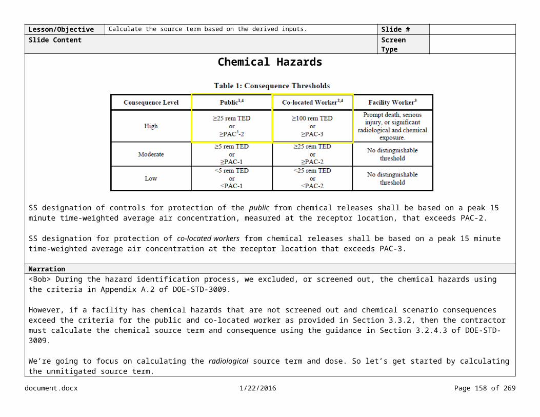
interacts with some fixed object, such as the ground, which is described by roughness length, or with a building, which is described by aerodynamic effects such as wake or cavity. The horizontal wind speed used in Gaussian models is based on the average wind speed over a selected time, usually fifteen minutes or one hour. Programming Instructions
Media Instructions
sba130_01_05_05_01.mp3sba130_01_05_05_02.mp3sba130_01_05_05_03.mp3
document.docx 1/22/2016 Page 158 of 204

Lesson/Objective Calculate the dose consequence based on the derived X (chi)/Q value. Slide #Slide Content Screen Type
Factors Affecting Airflow in Atmospheric Releases–Release Height
Narration<Ava> Another factor affecting dispersion and dilution of atmospheric releases is the height of the release above the ground.
An elevated release may skip receptors closer to the source, but affect those further away. It may also dilute more before reaching the ground. A release may be elevated if it occurs through a stack or if it is buoyed by a positive temperature difference between the release and the surrounding air, as might occur if the release is caused by a fire. To be considered elevated, the stack height must exceed twice the height of adjacent structures.
Section 3.2.4.2 of DOE-STD-3009 requires a non-buoyant, ground-level, point source release. Programming Instructions
document.docx 1/22/2016 Page 159 of 204
Non-buoyant, Ground Level
Artist – Make this graphic similar style as others.

Media Instructionssba130_01_05_06_01.mp3sba130_01_05_06_02.mp3sba130_01_05_06_03.mp3sba130_01_05_06_04.mp3
document.docx 1/22/2016 Page 160 of 204

Lesson/Objective Calculate the dose consequence based on the derived X (chi)/Q value. Slide #Slide Content Screen Type
Factors Affecting Airflow in Atmospheric Releases–Stability ClassSelect each for an enlarged view.
Stability Class
Definition Description
A Extremely Unstable Normally occurs during bright sunshine with relatively low wind speed (< 3 m/s).
B Moderately Unstable
Normally occurs during conditions that range from bright sunshine, with wind speeds in the 3 to 5 m/s range, to dim sunshine, with wind speeds < 2 m/s.
C Slightly Unstable Normally occurs during conditions that range from bright sunshine with wind speeds in the 5 to 6 m/s range, to dim sunshine with wind speed in the 2 to 3 m/s range.
D Neutral Normally occurs with moderate to dim sunshine, cloudy conditions, and at night, with wind speeds > 3 m/s. It also occurs with very strong wind speeds on either sunny or cloudy days. It usually is the most frequent of the stability classes.
E Slightly Stable Normally occurs at night or early morning with some cloud cover and with wind speeds in 2 to 5 m/s range.
F Moderately Stable Normally occurs at night or early morning with little cloud cover and with relatively low wind speeds (< 3 m/s).
G Extremely Stable Normally occurs at night or early morning with very light to nearly zero wind speed (calm wind conditions).
document.docx 1/22/2016 Page 161 of 204

Narration<Ava> The rate at which turbulence diffuses radioactive and toxic chemical emissions depends upon the stability of the atmosphere. The term "stability" refers to the rate of mixing within the atmospheric boundary layer. To categorize the different states of turbulence in the atmosphere, we use Pasquill stability classes. The rating provides an indication of how unstable the atmosphere is, which affects how rapidly a parcel of air is mixed and dispersed, or the degree of spatial dilution.
<Ava> Several methods exist to convert measured or observed meteorological data into atmospheric stability class data. Two methods are recommended: one is based on NRC guidance and the other is based on EPA guidance. Refer to DOE-HDBK-xxxx for additional information.
<Ava> More stable air causes the plume to stay concentrated further downwind.
<Ava> As you can see, as the stability of the air changes during the day due to temperature and wind. The shape of the plume also changes.
Programming Instructions
Media Instructionssba130_01_05_07_01.mp3sba130_01_05_07_02.mp3sba130_01_05_07_03.mp3sba130_01_05_07_04.mp3
document.docx 1/22/2016 Page 162 of 204

document.docx 1/22/2016 Page 163 of 204

Lesson/Objective Calculate the dose consequence based on the derived X (chi)/Q value. Slide #Slide Content Screen Type
Factors Affecting Airflow in Atmospheric Releases–Surface RoughnessSelect each for an enlarged view.
Narration<Ava> Another factor affecting the calculation of atmospheric dispersion is surface roughness. Surface roughness affects mechanical turbulence and the horizontal and vertical dispersion coefficients used in the calculation.
Mechanical turbulence is generated as wind flows over and around obstacles on the earth’s surface. These obstacles include natural topography and vegetation, as well as man-made structures.
In general, the rougher the terrain underneath the atmosphere, the greater the mechanical turbulence, diffusion, and vertical dispersion. Also, the vertical dispersion typically increases by one stability class for urban areas due to the additional mechanical turbulence generated by the buildings.
<Ava> There are several approaches for estimating surface roughness, but one of the commonly used methods is based on matching the site observations with a guidance table. For additional information on surface roughness, refer to Appendix E in DOE-HDBK-xxxx.
<Ava> Section 3.2.4.2 of DOE-STD-3009 identifies specific parameters to be used when using DOE-approved codes to calculate chi over Q. Programming Instructions
Media Instructionssba130_01_05_08_01.mp3sba130_01_05_08_02.mp3sba130_01_05_08_03.mp3
document.docx 1/22/2016 Page 164 of 204

Lesson/Objective Calculate the dose consequence based on the derived X (chi)/Q value. Slide #Slide Content Screen Type
Selecting an Atmospheric Dispersion Model
Select each option to learn more.
Option 1 –NRC Guide 1.145
Option 1: The first option is to follow the process based on Nuclear Regulatory Commission (NRC) Regulatory Guide 1.145, Atmospheric Dispersion Models for Potential Accident Consequence Assessments at Nuclear Power Plants.
This option allows for the determination of X/Q to be based on either a directionally independent method or a directionally dependent method.
Using this option, the value of X/Q can be accomplished manually using a spreadsheet.
In the case of Option 1, Reg Guide 1.145 allows for the application of a plume meander that incorporates the effects of light winds and buildings.
Option 2 – DOE-Approved Toolbox Code
Option 2: The next option is to use a DOE-approved toolbox code and apply the conservative parameters. Toolbox code is a term used to identify qualified software listed in the DOE Safety Software Central Registry (http:/energy.gov/ehss/safety-software-quality-assurance-central-registry).
For codes that do not contain fixed values or calculate the parameters internally, the following parameters shall be used for ensuring conservative calculation of offsite doses in accordance with Option 2:
Non-buoyant, ground level, point source release Plume centerline concentrations for calculation of dose consequences Rural dispersion coefficients A deposition velocity of 0.1 cm/sec for unfiltered release of particles(1-10 μm Aerodynamic Equivalent Diameter),
0.01 cm/sec for filtered particles, or 0 cm/sec for tritium/noble gases A surface roughness of 3 cm A minimum wind speed of 1 m/s Plume meander may be used, consistent with the accident release duration and the appropriate code guidance Building wake factors should not be credited in the plume dispersion, outside of those already incorporated into
plume meander
Option 3 – Site Specific
Option 3: The last option is to use site-specific methods and parameters as defined in a site/facility specific DOE-approved modeling protocol.
Accidents with unique dispersion characteristics, such as fires and explosions, may be modeled using phenomenon-specific codes that more accurately represent the release conditions.
When Option 3 is used, the modeling protocol shall address the appropriateness of the model to the site-specific situation, show that the overall result (i.e., radiological dose consequence) is conservative, and be submitted to the DOE Safety Basis Approval Authority for approval prior to use.
document.docx 1/22/2016 Page 165 of 204

Narration<Ava> According to DOE-STD-3009, there are three options for calculating atmospheric dispersion and the resulting chi over Q. The typical method is option 2, using a computer code such as the MELCOR Accident Consequence Code System (or MACCS). When reviewing DSAs, remember that the methodology and guidelines are specific to the option the contractor selected. Take a moment to review the three options.Programming Instructions
Media Instructionssba130_01_05_09.mp3
document.docx 1/22/2016 Page 166 of 204

Lesson/Objective Calculate the dose consequence based on the derived X (chi)/Q value. Slide #Slide Content Screen Type
NRC Regulatory Guide 1.145 (Directionally-Independent vs Directionally-Dependent) Selection each method to learn more.
Directionally-Independent
The pre-Regulatory Guide 1.145 methodology centered on a directionally-independent methodology to characterize atmospheric dispersion conditions. The meteorological conditions assumed were a very stable atmosphere and a light wind speed corresponding closely to a Pasquill “F” stability class and a 1 meter/sec wind speed. This stability and wind speed combination represents an infrequent and conservative atmospheric dispersion situation.
Using the directionally-independent methodology, X/Q values are determined by first calculating individual X/Q values for hourly pairs of wind and atmospheric stability conditions, independent of direction, at a distance equal to the shortest radial distance between the facility and exclusion area boundary.
These individual X/Q values are used to generate a cumulative probability distribution of X/Q values.
From this probability distribution, the X/Q value that is exceeded 5% of the time around the entire exclusion area boundary is selected for consequence calculations.
This approach is referred to as the directionally-independent method representing the 95th percentile calculation of X/Q.
Directionally-Dependent
The NRC considered that a more realistic evaluation of the determination of X/Q was needed and a parametric study was conducted and documented in NUREG/CR-2260.
It was evident that by accounting for wind direction data and actual boundary distances, the likelihood that the directionally independent 5% X/Q value would be equaled or exceeded in a specified sector would be less than 5%.
Therefore, NRC Regulatory Guide 1.145 allows for another option in the determination of X/Q, which is the directionally-dependent method that represents a 99.5th percentile calculation.
Narration<Ava> Let’s look at the NRC Regulatory Guide 1.145 as all three options rely on its guidance for the determination of chi over Q.
The NRC NUREG/CR-2260, Technical Basis for Regulatory Guide 1.145, Atmospheric Dispersion Models for Potential Accident Consequence Assessments of Nuclear Power Plants, provides a basis for the regulatory positions presented in Regulatory Guide 1.145. Programming Instructions
Media Instructionssba130_01_05_10.mp3
document.docx 1/22/2016 Page 167 of 204

Lesson/Objective Calculate the dose consequence based on the derived X (chi)/Q value. Slide #Slide Content Screen Type
Meteorological Data for Dispersion ModelingThe DOE-STD-3009 guidelines for calculating offsite doses include:
Five years of representative, recent meteorological data shall be used as input to the dispersion model. If five years of data is not available, justification for using a smaller data set shall be provided in the DSA. If representative meteorological data is not available, Pasquill stability class F and one meter/second wind speeds may be used, as
this approximates the 95th percentile dispersion condition.
Option specific guidelines from DOE-STD-3009 include: In the case of Option 1, follow the meteorological data guidance within NRC’s Regulatory Guide 1.23, Meteorological Monitoring
Programs for Nuclear Power Plants. For Options 2 and 3, the guidance in both Reg Guide 1.23 and in Environmental Protection Agency (EPA)-454/R-99-005, Meteorological
Monitoring Guidance for Regulatory Modeling Applications, are acceptable means of generating the meteorological data upon which dispersion is based.
In the development of the meteorological database for Option 3, the impact of local surface roughness on the data may be considered.
Narration<Ava> In the DSA, the contractor must describe the methodologies used to prepare the modeling parameters and include sufficient information to allow for the establishment of the technical basis for the dispersion modeling result.
A basic rule of thumb is to use at least five years of meteorological data as an input into the dispersion model. DOE-STD-3009 specifies that the latest five years of data should be used as an input and recommends that the 95th or 99.5th percentile value be used. A re-analysis is needed only every ten years, as the average of meteorological parameters change relatively slowly over time. Programming Instructions
Media Instructionssba130_01_05_11.mp3
document.docx 1/22/2016 Page 168 of 204

Lesson/Objective Calculate the dose consequence based on the derived X (chi)/Q value. Slide #Slide Content Screen Type
Release and Exposure DurationsSelect each option to learn more.
Option 1
For Option 1, the release and exposure durations should reflect Regulatory Position 1.3 in Reg Guide 1.145.
Regulatory Position 1.3 identifies a two-hour release duration to be used in calculating X/Q values.
Option 2 and 3
The guidelines for release and exposure duration from DOE-STD-3009 for Option 2 and 3 include: The dose estimate, unless otherwise established, is calculated based on an exposure duration of two
hours. This nominal exposure time may be extended to a period not to exceed eight hours for scenarios that
are slow to develop, as defined by the source term release rate (e.g., evaporation from a pool). Similarly, the nominal exposure time may also be shortened to a period no less than three minutes
(e.g., explosions and small fires).
The exposure period begins when the plume reaches the MOI. Exposure is defined in terms of plume passage at receptor location. The accident progression should not be defined using only input variables that maximize dispersion and minimize exposure and should ensure internal consistency between the accident release, exposure duration, and factors such as plume meander.
It is not acceptable to use a release rate that is specifically intended to expose the MOI to only a small fraction of the total material released, to define the time and wind speed so that the plume does not reach the MOI, or to enhance meander factors beyond what the release characteristics would warrant.
Narration<Ava> Another parameter used in the atmospheric dispersion model is the release and exposure duration. Take a moment to review the guidelines from DOE-STD-3009 and Regulatory Guide 1.145. Programming Instructions
Media Instructionssba130_01_05_12.mp3
document.docx 1/22/2016 Page 169 of 204
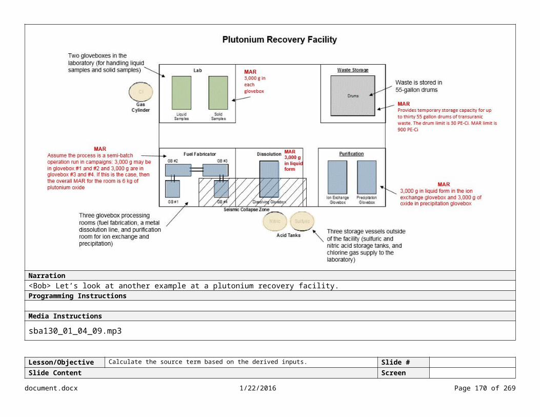
Lesson/Objective Calculate the dose consequence based on the derived X (chi)/Q value. Slide #Slide Content Screen Type
Mapping Receptor Locations
Narration<Ava> The receptor location is also another parameter used as an input to the atmospheric dispersion model. Remember that the receptor location for the co-located worker is 100 meters from the facility or estimated release point.
However, we still need to determine the receptor location for the MOI, or public. As you can see from this example, the source location is the center of the coordinate system. <Highlight center> The site boundary is illustrated by the red line. <Highlight boundary> The blue dots represent the receptor location at the minimum distance to the site boundary within each of the sixteen 45-degree sectors.<Highlight receptors> We now have the receptor locations, in meters, for the sixteen sectors. <Show table>
Based on five years of meteorological data for the site, such as wind speed, direction, atmospheric stability, and precipitation, we can calculate hourly-averaged data sets for each sector. This approach is used to calculate a directionally-independent 95th percentile chi over Q. Programming Instructions
Media Instructionssba130_01_05_13.mp3
document.docx 1/22/2016 Page 170 of 204

Lesson/Objective Calculate the dose consequence based on the derived X (chi)/Q value. Slide #Slide Content Screen Type
Determination of X/Q Select each option to learn more.
Onsite X/Q
According to DOE-STD-3009, a χ/Q value of 3.5 x 10⁻³ sec/m3 shall be used for ground-level release evaluation at the 100 meter receptor location, unless an alternate onsite χ/Q value is justified.
This value may not be appropriate for certain unique situations such as operations not conducted within a physical structure. When an alternate value is used, the DSA shall provide a technical basis supporting the need for the alternate value and the value selected.
Directionally Dependent (Offsite X/Q)
For the directionally dependent method, the MOI is at the site boundary location with the highest dose (ground level release).
According to DOE-STD-3009, the directionally dependent MOI is calculated in a manner consistent with Regulatory Position 1.2 of Regulatory Guide 1.145.
The directional dependence of the distance for the receptors may be calculated for 16 compass directions (22.5-degree sectors centered on true north, northeast, etc.).
For each of the 16 sectors, the distance to the receptor at the site boundary corresponds to the minimum distance to the site boundary within a 45-degree sector centered on the compass direction of interest.
According to DOE-HDBK-xxxx, the directionally dependent value is calculated by creating a cumulative probability distribution for each sector, determining the 99.5th percentile for each sector, and choosing the maximum value.
Each distribution should be described in terms of probabilities of given X/Q values being exceeded in that sector during the total time. For each of the 16 curves, the X/Q value that is exceeded 0.5 percent of the total number of hours in the data set should be selected. These are the sector X/Q values. The highest of the 16 sector values is defined as the maximum sector X/Q value.
Directionally Independent (Offsite X/Q)
For the directionally independent method, the MOI is at the shortest distance to the site boundary.
In the case of an elevated or buoyant release, the MOI could be beyond the DOE site boundary. In such cases, the MOI is evaluated where the ground level consequence is maximized. The presence of complex terrain should be evaluated during the analysis of elevated or buoyant releases and the model choices should reflect the existence of complex terrain.
According to DOE-HDBK-xxxx, the directionally independent MOI is calculated by creating a cumulative probability distribution for all sectors combined, based on all the meteorological annual data and using the actual site boundary distance for each sector and choosing the 95th percentile value.
document.docx 1/22/2016 Page 171 of 204

Narration<Ava> Let’s examine the specific guidelines for calculating chi over Q for both the onsite and offsite receptor. Notice that there are two options for calculating the receptor location for the MOI. The MOI is typically located either at the shortest distance to the DOE site boundary (directionally independent), or at the site boundary location with the highest dose based on a ground level release (directionally dependent).
When reviewing the DSA, be sure to refer to Section 3.2.4.2 of DOE-STD-3009 for specific guidelines for each option. Programming Instructions
Media Instructionssba130_01_05_14.mp3
document.docx 1/22/2016 Page 172 of 204

Lesson/Objective Calculate the dose consequence based on the derived X (chi)/Q value. Slide #Slide Content Screen Type
X/Q Example
Accident Scenario 95th Percentile Site Boundary X/Q
(s/m3)(1 cm/s deposition/38
cm surface roughness)
Fire Accident – 2.5 MW plume 1.97E-05Fire Accident – 3.0 MW plume 1.75E-05Fire Accident – 4.0 MW plume 1.43E-05Fire Accident – 5.0 MW plume 1.23E-05Fire Accident – 10.0 MW plume 7.62E-06Fire Accident – 25.0 MW plume 3.95E-06Spill Accident – Non-buoyant release
5.74E-05
Narration<Ava> Let’s take a look at some specific chi over Q values. This table provides the 95th percentile chi over Q values at the site boundary. All the scenarios were calculated using a ground-level release, 38 cm surface roughness, 1 cm/s deposition velocity, and a D stability class.
To be conservative we select the largest chi over Q value. <Highlight spill> A non-buoyant release for a spill accident is selected as it identifies the largest chi over Q value even though we are looking at a fire scenario. It is important to keep in mind that the fire scenario is initiated within a building; therefore, the non-buoyant release chi over Q is selected.Feedback Instructions sba130_01_05_15.mp3
NotesTA-55, Chapter 3, states the following: “Potential plume buoyancy from fire heating was not considered, although a number of effective release heights were evaluated to simulate the effects of initial plume velocity with the largest chi/Q carried forward to consequence calculations.” A non-buoyant release, i.e., a spill, is selected as it identifies the largest chi/Q value even though we are looking at a fire scenario. To be conservative we select the largest chi/Q value.
document.docx 1/22/2016 Page 173 of 204

Lesson/Objective Calculate the dose consequence based on the derived X (chi)/Q value. Slide #Slide Content Screen Type
X/Q Knowledge Check
What is the X/Q value for this scenario? Enter the value in the table.
ID # Type Scenario Initiating Event or Cause
Description Likelihood Consequence RiskP CW W P CW W
F-04 Operational Accident/Fire
Furnace temperature excursion, combustibles adjacent to furnace, fire inside glovebox, and glovebox breach
Furnace malfunction Uncontrolled U H H H I I I
Control MAR DR ARF RF LPF ST X/Q
CW PUnmitigated 9,000 g 1.0 1E-2 1.0 1.0 90 g 3.5 x 10⁻³ 5.74E-05
Accident Scenario 95th Percentile Site
Boundary X/Q (s/m3)
(1 cm/s deposition/38 cm surface roughness)
Fire Accident – 2.5 MW plume 1.97E-05Fire Accident – 3.0 MW plume 1.75E-05Fire Accident – 4.0 MW plume 1.43E-05Fire Accident – 5.0 MW plume 1.23E-05Fire Accident – 10.0 MW plume 7.62E-06Fire Accident – 25.0 MW plume 3.95E-06Spill Accident – Non-buoyant release 5.74E-05
Narration<Ava> Using the values in this table, we can determine the chi over Q value for the furnace malfunction scenario. Remember that Section 3.2.4.2 of DOE-STD-3009 recommends a non-buoyant, ground-level release for the selection of the most conservative chi over Q. What is the chi over Q value for this scenario? Feedback Instructions Try again. Use the table to locate the X/Q value for the non-buoyant release. Incorrect. <Show visual feedback> Per DOE-STD-3009, the X/Q value for the co-located worker is 3.5 x 10⁻³ sec/m3. The X/Q value for the public is 5.74E-05 (using the non-buoyant release X/Q value from the table). That’s correct.Media Instructionssba130_01_05_16.mp3
document.docx 1/22/2016 Page 174 of 204

Lesson/Objective NA Slide #Slide Content Screen Type
Calculating DoseSelect each term to learn more.
Narration
Programming Instructions
Media Instructions
document.docx 1/22/2016 Page 175 of 204
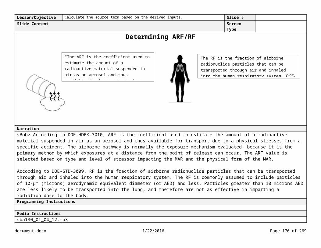
Lesson/Objective Calculate the dose consequence based on the derived X (chi)/Q value. Slide #Slide Content Screen Type
Identifying Breathing Rate
Activity Level Breathing Rate (m3/s)Chronic 2.66 x 10⁻⁴
Light 3.33 x 10⁻⁴
Heavy 3.47 x 10⁻⁴
ICRP 2
Narration<Ava> The next value in the calculation is breathing rate. DOE-STD-3009, Section 3.2.4.2, requires a breathing rate of 3.3E x 10-4 m3/s for both the public and co-located worker. This value is equivalent to “light work” as defined in ICRP Publication 68. The reference man is a 30-year old Caucasian male. Programming Instructions
Media Instructionssba130_01_05_17.mp3
document.docx 1/22/2016 Page 176 of 204

Lesson/Objective Calculate the dose consequence based on the derived X (chi)/Q value. Slide #Slide Content Screen Type
Breathing Rate for Furnace Malfunction Scenario
ID # Type Scenario Initiating Event or Cause
Description Likelihood Consequence RiskP CW W P CW W
F-04 Operational Accident/Fire
Furnace temperature excursion, combustibles adjacent to furnace, fire inside glovebox, and glovebox breach
Furnace malfunction Uncontrolled U H H H I I I
Control MAR DR ARF RF LPF ST X/Q BR
CW PUnmitigated 9,000 g 1.0 1E-2 1.0 1.0 90 g 3.5 x 10⁻³ 5.74E-05 3.3E-4 m3/s
Narration<Ava> Following the guideline in DOE-STD-3009, we’ll use the same breathing rate for both the co-located worker and the public.
Programming Instructions
Media Instructionssba130_01_05_18.mp3
document.docx 1/22/2016 Page 177 of 204

Lesson/Objective NA Slide #Slide Content Screen Type
Calculating Radiological Dose
Select each term to learn more.
Narration
Programming Instructions
Media Instructions
document.docx 1/22/2016 Page 178 of 204
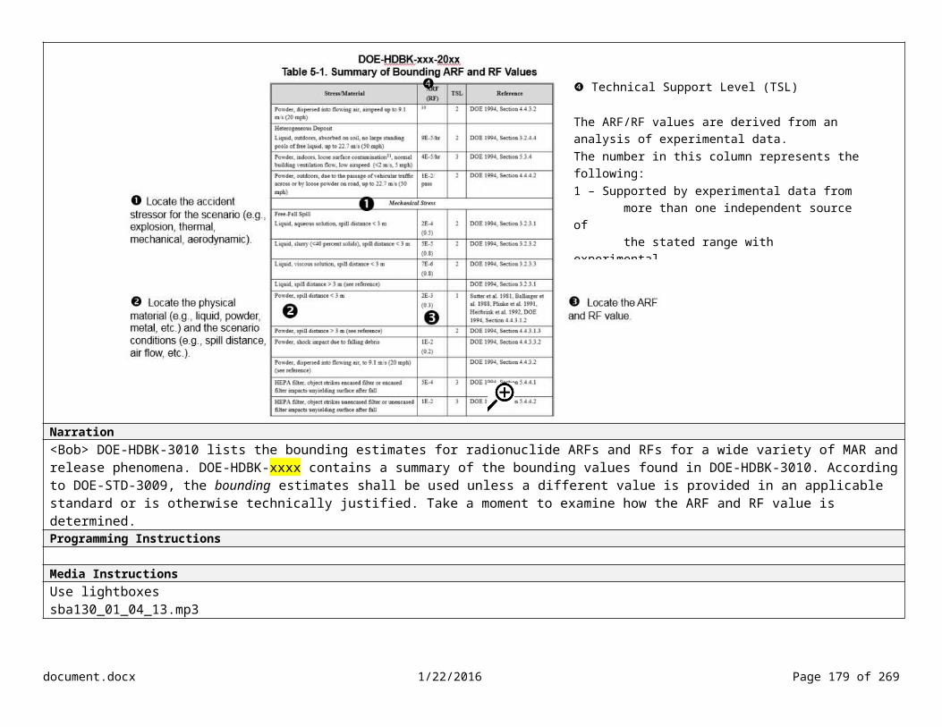
Lesson/Objective Calculate the dose consequence based on the derived X (chi)/Q value. Slide #Slide Content Screen Type
Calculating Dose Conversion FactorSelect each icon to learn more.
ICRP 68 (Workers)
According to DOE-STD-3009, dose coefficients consistent with ICRP Publication 68, Dose Coefficients for Intakes of Radionuclides by Workers, shall be used to calculate the DCF for the co-located worker. The DCFs from ICRP-68 can also be found in Table A.1 of ICRP-119 (for inhalation).
ICRP 72(Public)
According to DOE-STD-3009, dose coefficients consistent with ICRP 72, Age-dependent Doses to Members of the Public from Intake of Radionuclides, shall be used to calculate the DCF for the public. The DCFs for the public can also be found in Table G.1 of ICRP-119 (for inhalation).
document.docx 1/22/2016 Page 179 of 204

Narration<Ava> The amount of biological damage that radioactive material may inflict on an organ or tissue is given by the dose conversion factor (or DCF). It provides a measure of the biological effect of being exposed to different forms of radiation (alpha, beta, neutron, x-ray, or gamma). The chronic dose to an individual depends on how much of the radionuclide goes to the blood or GI tract. Different radionuclides in different chemical forms are absorbed in bodily fluids at different rates.
The DCFs take into account the migration of the radioisotope within the body, the decay of the radioisotope, and the formation of daughter isotopes that may be radioactive. The DCF values are different for the co-located worker and the public. Programming Instructions When user selects marker, show text:
Co-located Workers DCFs are provided for both inhalation and ingestion. In most cases, inhalation is of primary interest in nonreactor nuclear facilities.
DCFs are given for two particulate size distributions, centered at 1 μm and 5 μm. These sizes are referred to as AMAD, the median diameter of a lognormal size distribution. ICRP 68 recommends that the 5-μm AMAD DCFs be used unless the analyst can justify the use of the DCFs for the 1-μm AMAD. An exception would be for the case in which the particulates had passed through high-efficiency particulate air (HEPA) filtration, in which case the 1-μm AMAD would be more appropriate.
“Fast” refers to those compounds that dissolve quickly and are absorbed into the respiratory tissue where they are initially deposited, or directly into the blood, in minutes to hours. There is virtually no time for these compounds to be transported to other respiratory sites.
“Moderate” refers to those compounds that dissolve more slowly. Only a small portion (modeled as 10 percent) is absorbed directly into respiratory tissue at the initial deposit site, or directly into blood. The remainder is transformed (in a period of weeks) into a more soluble compound. While in this transformed state, it can be transported to other respiratory tissues. Eventually, it is dissolved into the blood and thus is available for transport to other parts of the body.
document.docx 1/22/2016 Page 180 of 204

“Slow” refers to those compounds that are essentially insoluble. Almost none of this material is absorbed directly into the tissue at the initial deposit site, or directly into the blood. It is slowly transformed into a more soluble compound (on a time scale of years). While in this transformed state, it can be transported to other respiratory tissues. Eventually, it is dissolved into the blood and thus is available for transport to other parts of the body.
For inhalation, the dose conversion factor is typically expressed in units of rem/Ci, which can be converted to Sv/g or rem/g by multiplying by the specific activity.
Public The radionuclides in ICRP 72 are categorized into three classes. Y - Radionuclides in insoluble compounds typically remain in the lungs for a long time; these are of Solubility Class Y (for years) (also called Lung Clearance Class Y).W - Radionuclides in moderately soluble compounds remain in the lungs for weeks; these are of Solubility Class W (for weeks) (also called Lung Clearance Class W).D - Radionuclides in soluble compounds remain in the lungs for only a short time; these are of Solubility Class D (for days) (also called Lung Clearance Class D).
The particulate size distribution used is 1-μm AMAD. DCFs generally are larger for smaller particle sizes.
Add hyperlink: http://www.icrp.org/publication.asp?id=ICRP%20Publication%20119Media Instructionssba130_01_05_19.mp3
document.docx 1/22/2016 Page 181 of 204

Lesson/Objective Calculate the dose consequence based on the derived X (chi)/Q value. Slide #Slide Content Screen Type
Determining DCF for Furnace Malfunction Knowledge CheckUsing the tables in ICRP 119, what is the DCF value for the public and co-located worker for Pu-239? Enter the values in the table below.
ID # Type Scenario Initiating Event or Cause
Description Likelihood Consequence RiskP CW W P CW W
F-04 Operational Accident/Fire
Furnace temperature excursion, combustibles adjacent to furnace, fire inside glovebox, and glovebox breach
Furnace malfunction Uncontrolled U H H H I I I
Control MAR DR ARF RF LPF ST X/Q BR DCF
CW P CW PUnmitigated 9,000 g 1.0 1E-2 1.0 1.0 90
g 3.5 x 10⁻³ 5.74E-
053.3E-4m3/s
8.3E-06 1.6E-05
Narration<Ava > Now we need to determine the DCF for both the co-located worker and public. For this scenario, use Pu-239 as the radionuclide and Category S. Category S (or slow) is assigned to materials that are less soluble in water. Aerosol particles produced by metal fires or from mechanical impact on finely divided oxide powders fall into this category. Category S applies to the accident we are reviewing. Programming Instructions
Feedback InstructionsTry again. For the co-located worker value, ICRP 68 recommends that the 5-μm AMAD DCFs be used (unless the analyst can justify the use of the DCFs for the 1-μm AMAD). Ensure you are referencing the Slow type in both tables. Incorrect. <Show answer> The DCF value for the co-located worker in Table 1 for Pu-239 is 8.3E-06. The DCF value for the public in Table G-1 is 1.6E-05. Correct.Media Instructionssba130_01_05_20.mp3
Co-located worker Table A-1 Public Table G-1
document.docx 1/22/2016 Page 182 of 204

document.docx 1/22/2016 Page 183 of 204

Lesson/Objective Calculate the dose consequence based on the derived X (chi)/Q value. Slide #Slide Content Screen Type
Conversion from Sv/Bq to Rem/G
1. Multiply value by 3.7E+10 Bq/Ci: Public – 1.6E-5 Sv/Bq X 3.7E+10Bq/Ci = 5.92E+5 Sv/Ci CW – 8.3E-6 Sv/Bq X 3.7E+10Bq/Ci = 3.07E+5 Sv/Ci
2. Multiply by 100 rem/Sv: Public – 5.92E+5 Sv/Ci X 100 rem/Sv = 5.92E+7 rem/Ci CW – 3.07E+5 SV/Ci X 100 rem/Sv = 3.07E+7 rem/Ci
3. Multiply by specific activity for Pu, 6.211E-2 Ci/g: Public – 5.92E+7 rem/Ci X 6.211E-2 Ci/g = 3.677E+5 rem/g CW – 3.07E+7 rem/Ci X 6.211E-2 Ci/g = 1.907E+6 rem/g
Control MAR DR ARF RF LPF ST X/Q BR DCF
CW P CW PUnmitigated 9,000 g 1.0 1E-2 1.0 1.0 90
g 3.5 x 10⁻³ 5.74E-
053.3E-4m3/s
1.907E+6 rem/g 3.677E+5 rem/g
Narration<Ava > There is one more step when determining the DCF. The DCF values in ICRP-68 are given in international units, in this case Sv/Bq. We need to convert the value to conventional units, which is rems per gram. Take a moment to review the steps for the conversion. Programming Instructions
Feedback Instructions
Media Instructionssba130_01_05_21.mp3
document.docx 1/22/2016 Page 184 of 204

Lesson/Objective NA Slide #Slide Content Screen Type
Calculating Radiological DoseSelect each term to learn more.
Narration
Programming Instructions
Media Instructions
document.docx 1/22/2016 Page 185 of 204
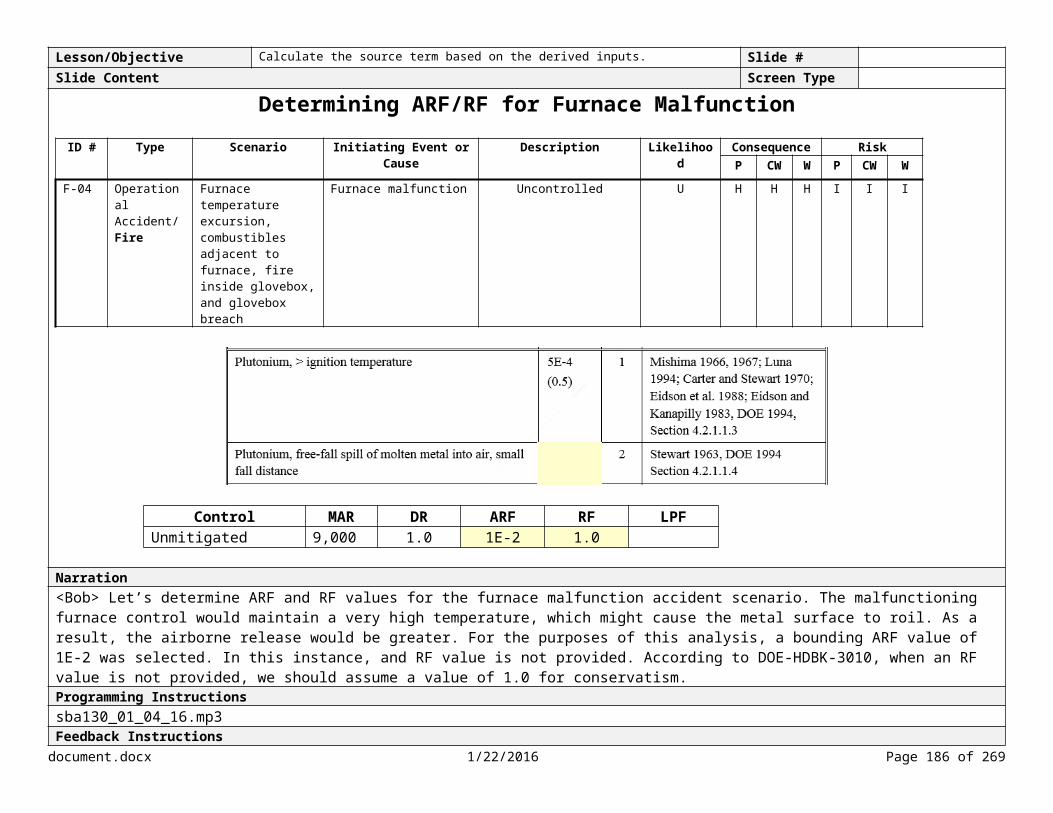
Lesson/Objective Calculate the dose consequence based on the derived X (chi)/Q value. Slide #Slide Content Screen Type
Calculating Radiological Dose
Step 1. Calculate the dose to source term ratio (DSTR) (X/Q * BR * DCF)
Step 2. Calculate the dose (DSTR * ST)
Narration<Ava> It looks like we’re ready to determine the radiological dose. To simplify the process, we’re going to use a two-step process. First, we’ll calculate the dose to source term ratio, and then the dose. The formula for calculating the dose to source term is chi over Q, multiplied by the breathing rate, multiplied by the dose conversion factor. To calculate the dose, simply multiply the dose to source term ratio by the source term. Programming Instructions Media Instructionssba130_01_05_22.mp3
document.docx 1/22/2016 Page 186 of 204

Lesson/Objective Calculate the dose consequence based on the derived X (chi)/Q value. Slide #Slide Content Screen Type
Dose to Source Term Ratio
ID # Type Scenario Initiating Event or Cause
Description Likelihood Consequence RiskP CW W P CW W
F-04 Operational Accident/Fire
Furnace temperature excursion, combustibles adjacent to furnace, fire inside glovebox, and glovebox breach
Furnace malfunction Uncontrolled U H H H I I I
Control MAR DR ARF RF LPF ST X/Q BR DCF Dose to
Source Term Ratio (DSTR)
Dose (rem)
CW P CW P CW P CW PUnmitigated 9,000 g 1.0 1E-2 1.0 1.0 90
g3.5 x 10-3
5.74E-05
3.3E-4 m3/s
1.907E+6 rem/g
3.677E+5
rem/g
Narration<Ava> We’ll need to calculate the dose to source term ratio for both the co-located worker and the public. The dose to source term ratio for the co-located worker is ###. The dose to source term ratio for the public is ####. Programming Instructions Media Instructionssba130_01_05_23.mp3
document.docx 1/22/2016 Page 187 of 204

Lesson/Objective Calculate the dose consequence based on the derived X (chi)/Q value. Slide #Slide Content Screen Type
Radiological Dose Knowledge CheckWhat is the dose for the public and co-located worker for this scenario? Enter the values in the table below.
ID # Type Scenario Initiating Event or Cause
Description Likelihood Consequence RiskP CW W P CW W
F-04 Operational Accident/Fire
Furnace temperature excursion, combustibles adjacent to furnace, fire inside glovebox, and glovebox breach
Furnace malfunction Uncontrolled U H H H I I I
Control MAR DR ARF RF LPF ST X/Q BR DCF Dose to
Source Term Ratio (DSTR)
Dose(rem)
CW P CW P CW P CW PUnmitigated 9,000 g 1.0 1E-2 1.0 1.0 90
g3.5 x 10-3
5.74E-05
3.3E-4 m3/s
1.907E+6 rem/g
3.677E+5
rem/g
# # # #
Narration<Ava> The last step is to calculate the dose for both the co-located worker and the public, which is the source term multiplied by the dose to source term. Programming Instructions Try again. To calculate the dose, use the formula ST * DSTR. Incorrect. <Show correct answer> The dose for the co-located worker is #. The dose for the public is #. That’s correct.Media Instructionssba130_01_05_24.mp3
document.docx 1/22/2016 Page 188 of 204

Lesson/Objective Identify the factors that should be considered when calculating source term and dose. Slide #Slide Content Screen Type
Calculating the Dose Knowledge CheckWhich of the following should be used as inputs when calculating the dose consequences? Select all that apply.
Five years of representative, recent meteorological data
Non-buoyant, ground level, point source release (for codes that do not contain fixed values or calculate the parameters)
Highest, most conservative X/Q
Two years of meteorological data
Narration
Programming Instructions Feedback InstructionsTry again. Take another look at Section 3.2.4.2 in DOE-STD-3009. Incorrect. When calculating dose consequences, use five years of representative data; a non-buoyant, ground level, point source release; and the highest, most conservative X/Q value. Correct. Media InstructionsAdd icon for DOE-STD-3009
document.docx 1/22/2016 Page 189 of 204

Lesson/Objective Calculate the dose consequence based on the derived X (chi)/Q value.Identify the requirements for documenting an accident analysis.
Slide #
Slide Content Screen Type Multiple Choice
Documenting the Consequence AnalysisWhich of the following should be documented in the Section 3.4.3.X.3 of the DSA? (Refer to Section 4 of the DOE-STD-3009)
Receptor location
X/Q
Unmitigated dose for the DBAs/EBAs
Phenomenological models
DOE-STD-3009Feedback goes here
Narration<Ava> When reviewing a DSA, ensure that the contractor documents the consequence analysis per Section 4 of DOE-STD-3009. Take a moment to review the requirements and answer this question.Programming Instructions
Feedback InstructionsTry again. Take another look at Section 4 of the DOE-STD-3009. This section should focus on the consequence analysis. Incorrect. Section 3.4.3.X.3 of the DSA should include the receptor location, X/Q, and the unmitigated dose for the DBAs/EBAs. The phenomenological models should be documented in Section 3.4.3.X.2, Source Term Analysis. That’s correct. Section 3.4.3.X.3 of the DSA should include the receptor location, X/Q, and the unmitigated dose for the DBAs/EBAs. The phenomenological models should be documented in Section 3.4.3.X.2, Source Term Analysis.Media Instructionssba130_01_05_25.mp3
document.docx 1/22/2016 Page 190 of 204
Submit

Lesson/Objective Calculate the dose consequence based on the derived X (chi)/Q value.Identify the requirements for documenting an accident analysis.
Slide #
Slide Content Screen TypeKey Points
Select each term to review the key points.
Narration
Programming InstructionsShow key points when user select each term.
X/Q χ/Q represents the dilution of the radioactive plume via dispersion and deposition as it travels from the facility during an accident. X is the concentration of the radionuclides or toxic chemicals in the air at some downwind location. Q is the constant rate of radionuclide or toxic chemical release. Chi/Q is the concentration of the radionuclides or toxic chemical in air at the receptor per unit source rate, or time-integrated concentration per unit
source (or S/m3). Wind speed, wind direction, surface roughness of the terrain, release height, and stability class affect atmospheric dispersion. Atmospheric dispersion can be calculated 1) manually following NRC Guide 1.145, 2) using DOE-approved toolbox code, or 3) using site-specific
methods. Per DOE-STD-3009, five years of representative, recent meteorological data shall be used as an input to the dispersion model. The minimum distance to the site boundary in 45°-wide sectors centered on 16 directions is used and the X/Q value for each hour during the year is
calculated (using either the 99.5th or 95th percentile). For the co-located worker, a χ/Q value of 3.5 x 10⁻³ sec/m3 shall be used for ground-level release evaluation at the 100-meter receptor location, unless
an alternate onsite χ/Q value is justified (per DOE-STD-3009).
BR
document.docx 1/22/2016 Page 191 of 204

Use a breathing rate of 3.3E x 10-4 m3/s for both the MOI and co-located worker.
DCF The dose conversion factor (DCF) presents the amount of biological damage that radioactive material may inflict on an organ or tissue. Dose coefficients consistent with ICRP 68 (for co-located workers) and ICRP 72 (for the public) shall be used. ICRP 68 recommends that the 5 μm AMAD DCFs be used unless the analyst can justify the use of the DCFs for the 1 μm AMAD (such as particulates
passing through HEPA filtration). ICRP 72 uses 1 μm AMAD.
Dose The dose is presented as a total effective dose (TED) based on an integrated committed dose to all target organs, accounting for direct exposures, as
well as a 5-year commitment. To simplify the process, the calculation can be performed in two steps: the dose to source term ratio (DSTR) (X/Q * BR * DCF) and then the source term
(ST * DSTR). The radiological dose must be calculated for both the co-located worker and the public/MOI. The dose is documented in Section 3.4.3.X.3 of the DSA.
Feedback Instructions
Media Instructions
document.docx 1/22/2016 Page 192 of 204

Lesson/Objective NA Slide #Slide Content Screen Type Menu
Menu
Purpose and Scope
Selecting DBAs/EBAs
Developing Formal Descriptions of Accident Scenarios
Calculating Radiological Source Term
Calculating Radiological Dose
Comparing Consequence Estimates to the EG and/or CW Threshold
Narration
Programming Instructions
Media Instructions
document.docx 1/22/2016 Page 193 of 204

Lesson/Objective Determine if a mitigated evaluation is required based on comparison of consequences to evaluation guidelines (EGs).
Slide #
Slide Content Screen TypeComparing Consequence Estimates to the EG and Co-located Worker Threshold
Narration<Bob> This is our last task for the unmitigated accident analysis. We need to compare the radiological dose consequences for our scenarios to the evaluation guideline for the public and to the threshold for the co-located worker. The evaluation guideline is not a safety standard, because it does not define an acceptable or unacceptable dose from an accident. It is a criterion used by DOE to help identify and evaluate the safety class controls necessary to avoid the potential dose from an accident. The evaluation guideline of 25 rem total effective dose for the public and 100 rem total effective dose for the co-located worker are documented in Table 1 in DOE-STD-3009.
Table 1 also lists the protective action criteria for chemical hazards that are not screened out during the hazard identification process.
When reviewing a DSA, ensure that the comparison of the unmitigated consequence thresholds are documented in Section 3.4.3.X.4 of the DSA. Programming Instructions
Media Instructionssba130_01_06_01.mp3
document.docx 1/22/2016 Page 194 of 204

Lesson/Objective Determine if a mitigated evaluation is required based on comparison of consequences to evaluation guidelines (EGs).
Slide #
Slide Content Screen Type
Process for Comparing Consequences to the EGSelect each receptor to learn more.
Public (MOI)
document.docx 1/22/2016 Page 195 of 204

Co-located Worker
Narration<Bob> Let’s examine the process for comparing the dose to the evaluation guideline for the public and the co-located worker threshold.
Public<Bob> A total effective dose of 25 rem is the evaluation guideline for the public. If the radiological dose exceeds 25 rem, then a safety class SSC is required per DOE-STD-3009. If preventive controls do not reduce the dose below the EG, then mitigative controls are incrementally credited. We’ll discuss this process and also what to do if no viable control strategy exists later in the week.
If the dose challenges the EG, that is, it’s greater than 5 and less than 25 rem, then a safety class SSC is recommended per DOE Guide 420.1-1. The concept of “challenging the EG” accounts for potential uncertainties in the accident analysis methodology.
If the dose is below 5 rem, then no safety class controls are required.
Co-located workerdocument.docx 1/22/2016 Page 196 of 204
<Bob> For co-located workers, an unmitigated radiological dose of 100 rem total effective dose at 100 meters from the release point shall be used as the threshold for designating safety significant controls. Programming Instructions
Media Instructionssba130_01_06_02_01.mp3sba130_01_06_02_02.mp3sba130_01_06_02_03.mp3
document.docx 1/22/2016 Page 197 of 204

Lesson/Objective Determine if a mitigated evaluation is required based on comparison of consequences to evaluation guidelines (EGs).
Slide #
Slide Content Screen Type
EG Knowledge Check (1 of 4) Does the radiological dose for this scenario exceed, challenge, or fall below the EG for the public?
HA-ID #
Type Scenario Initiating Event or Cause Description MOI Dose
F-10 Operational Accident/Fire
Fire in glovebox conducting aqueous chloride plutonium recovery operations (liquid fire)
Electrical short in equipment ignites combustibles in glovebox which in turn heat and ignite the organic extraction liquid
Uncontrolled
24.99 rem
Exceeds EG
Challenges EG
Falls below EG
Narration<Bob> Let’s examine some of the representative bounding and unique accidents we selected. For each scenario, determine if the dose exceeds, challenges, or falls below the EG. If the dose exceeds or challenges the EG, the accident scenario will be carried forward to the mitigated analysis. Programming Instructions
Feedback InstructionsTry again. What is the EG for the MOI (located in Table 1 of DOE-STD-3009)?Incorrect. The unmitigated dose to the MOI challenges the EG. The dose of 24.99 rem could be rounded to 25 rem, which exceeds the EG. To prevent or mitigate a potential release, safety-class SSCs would be required. Therefore, both answers are acceptable.That’s correct. Media InstructionsAdd Table 1 as icon.sba130_01_06_03.mp3
document.docx 1/22/2016 Page 198 of 204

Lesson/Objective Determine if a mitigated evaluation is required based on comparison of consequences to evaluation guidelines (EGs).
Slide #
Slide Content Screen Type
EG Knowledge Check (2 of 4) Does the radiological dose for this scenario exceed, challenge, or fall below the EG for the public?
HA-ID #
Type Scenario Initiating Event or Cause Description MOI Dose
HA-# Operational Accident/Loss of Containment
Container containing Pu238 dropped outside of glovebox Degraded or damaged container
Uncontrolled 2 rem
Exceeds EG
Challenges EG
Falls below EG Narration
Programming Instructions
Feedback InstructionsTry again. Take another look at Table 1 in DOE-STD-3009. Incorrect. <Show correct answer> The unmitigated dose to the MOI of 2 rem does not exceed or challenge the 25-rem EG for the MOI. No safety class SSCs are necessary.That’s correct. The unmitigated dose to the MOI of 2 rem does not exceed or challenge the 25-rem EG for the MOI. No safety class SSCs are necessary. Media Instructions
document.docx 1/22/2016 Page 199 of 204

Lesson/Objective Determine if a mitigated evaluation is required based on comparison of consequences to evaluation guidelines (EGs).
Slide #
Slide Content Screen Type
EG Knowledge Check (3 of 4) Does the radiological dose for this scenario exceed, challenge, or fall below the EG for the public?
HA-ID #
Type Scenario Initiating Event or Cause Description MOI Dose
HA-# External Event/Aircraft Crash
Aircraft crash Aircraft crashes into staging area or building causing a full facility (inside and outside) fire
Uncontrolled 19.1
Exceeds EG
Challenges EG
Falls below EG Narration
Programming Instructions
Feedback InstructionsTry again. Review the guidelines for challenging the EG located in DOE-STD-3009, Appendix A.10. Incorrect. The unmitigated dose to the MOI challenges the 25-rem DOE EG (5-25 rem). Therefore, safety-class controls that prevent or mitigate the accident are recommended per DOE Guide 420.1-1.That’s correct. The unmitigated dose to the MOI challenges the 25-rem DOE EG. Therefore, safety-class controls that prevent or mitigate the accident are recommended per DOE Guide 420.1-1.Media Instructions
document.docx 1/22/2016 Page 200 of 204

Lesson/Objective Determine if a mitigated evaluation is required based on comparison of consequences to evaluation guidelines (EGs).
Slide #
Slide Content Screen Type
EG Knowledge Check (4 of 4) Does the radiological dose for this scenario exceed or fall below the co-located worker threshold?
HA-ID #
Type Scenario Initiating Event or Cause Description DoseCW
HA-# Operational Accident/Fire
Furnace temperature excursion, combustibles adjacent to furnace, fire inside glovebox, and glovebox breach
Furnace malfunction Uncontrolled 100 rem
Exceeds CW Threshold
Falls below CW Threshold
Narration
Programming Instructions
Feedback InstructionsTry again. What is the threshold for the co-located worker? Incorrect. <Show correct answer> The unmitigated dose to the co-located worker is 100 rem, which meets/exceeds the threshold for the co-located worker. That’s correct. Media Instructions
document.docx 1/22/2016 Page 201 of 204
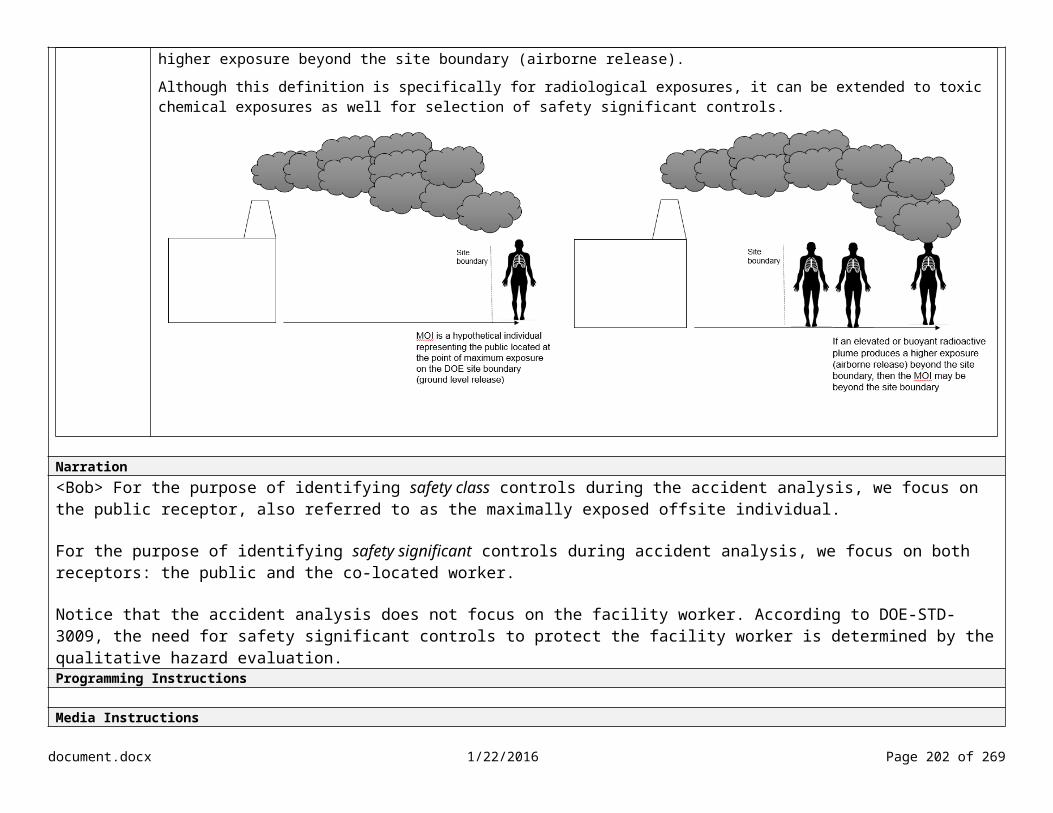
Lesson/Objective Determine if a mitigated evaluation is required based on comparison of consequences to evaluation guidelines (EGs).
Slide #
Slide Content Screen Type
Key PointsPublic/MOI
If the radiological dose exceeds 25 for the public, then a safety class SSC is required per DOE-STD-3009.
If the radiological dose challenges 25 rem (> 5 and < 25) for the public, then a safety class SSC is recommended per DOE Guide 420.1-1.
If the radiological dose falls below 25 rem for the public, then no safety class controls are required.
Accident scenarios that challenge or exceed the EG are carried forward into the mitigated analysis.
Co-located Worker
For co-located workers, an unmitigated radiological dose of 100 rem total effective dose at 100 meters from the release point shall be used as the threshold for designating safety significant controls.
Narration<Bob> Congratulations! You made it through the unmitigated accident analysis. During our next meeting, we’ll identify safety class controls for the accident scenarios that challenged or exceeded the EG. Programming Instructions
Media Instructionssba130_01_06_04.mp3
document.docx 1/22/2016 Page 202 of 204

Lesson/Objective Slide #Slide Content Screen Type
Topic Results Screen Summary
Overall Total Score: xx% (## points)
Overall Passing Score: 80% (## points)
Show Results for Topic 1 Show Results for Topic 2 Show Results for Topic 3 Show Results for Topic 4
Feedback goes here
Narration
Programming InstructionsAbove 80%: Congratulations! You successful completed the last topic for this course.
Below 80%: Try again. You did not pass this topic. Before continuing, reattempt the knowledge checks by selecting the Retry button. You must score at least 80% on the knowledge checks. Media InstructionsAdd a Topic Results slide at the end of every topic.
document.docx 1/22/2016 Page 203 of 204

Lesson/Objective Slide #Slide Content Screen Type
Lesson Results Screen Summary
Overall Total Score: xx% (## points)
Overall Passing Score: 80% (## points)
Show Results for Topic 1 Show Results for Topic 2 Show Results for Topic 3 Show Results for Topic 4
Feedback goes here
Narration
Programming InstructionsAbove 80%: Congratulations! You successful completed the first lesson in the course, Accident Analysis
Below 80%: Try again. You did not pass this lesson. Before continuing, reattempt the knowledge checks by selecting the Retry button. You must score at least 80% on the knowledge checks for each topic.Media Instructions
document.docx 1/22/2016 Page 204 of 204