Site Trials of Novel CO2 Capture Technology at Delta ...
75
0 CSIRO ENERGY FLAGSHIP Site Trials of Novel CO 2 Capture Technology at Delta Electricity Final Report Shi Su, Ramesh Thiruvenkatachari, Xinxiang Yu, Yonggang Jin CSIRO Energy Anthony Callen Delta Electricity May 2014 · EP146215
Transcript of Site Trials of Novel CO2 Capture Technology at Delta ...

0
CSIRO ENERGY FLAGSHIP
Site Trials of Novel CO2
Capture Technology at Delta
Electricity Final Report
Shi Su, Ramesh Thiruvenkatachari, Xinxiang Yu, Yonggang Jin
CSIRO Energy
Anthony Callen
Delta Electricity
May 2014 · EP146215

1

2
Important disclaimer
CSIRO advises that the information contained in this publication comprises general statements based on
scientific research. The reader is advised and needs to be aware that such information may be incomplete
or unable to be used in any specific situation. No reliance or actions must therefore be made on that
information without seeking prior expert professional, scientific and technical advice. To the extent
permitted by law, CSIRO (including its employees and consultants) excludes all liability to any person for
any consequences, including but not limited to all losses, damages, costs, expenses and any other
compensation, arising directly or indirectly from using this publication (in part or in whole) and any
information or material contained in it.

3

4
Acknowledgement
This project is part of the CSIRO Energy and received funding from the New South Wales Government as
part of the Coal Innovation NSW (CINSW). We gratefully acknowledge the in-kind contribution from Delta
Electricity. The contributions of Paul Feron, Aaron Cottrell, Ashleigh Cousins, Jun-Seok Bae and Sanger
Huang from CSIRO are kindly acknowledged. We would also like to acknowledge Andrew Castleden for the
preparation of 3D drawings of the test facility, Xianchun Li for the assistance with site trials, and Nawshad
Haque with Life Cycle Analysis. Special thanks are due to Clement Yoong and James Knight for their
coordination and support of the project.

5
Abstract
Growing concerns for global warming and climate change have attracted widespread efforts to develop
efficient and cost-effective technologies for Post-combustion CO2 Capture (PCC) from large point sources,
such as coal-fired power plants. Among various PCC technologies for CO2 capture from flue gas, use of
porous solid sorbents offers a promising solution as it has the potential to be highly cost-effective and has
less impact on the environment. From January 2006, CSIRO began to develop a new CO2 capture process by
developing nano-structured monolithic carbon fibre composite adsorbents, which are fabricated in a
honeycomb structure. This structure enables CO2 capture in a dry process in dusty environments with low
pressure drop. Compared with conventional solvent process, the carbon adsorbent CO2 capture exhibits the
following advantages: no degradation and secondary emissions, high resistance to NOx and SOx in the flue
gas, no need for flue gas pre-treatment, use of waste heat from the flue gas for CO2 desorption due to high
thermal conductivity. For the carbon adsorbents for the post combustion CO2 capture, studies so far have
been carried out only using simulated flue gas and under laboratory conditions. Hence, the site trials and
demonstration of the carbon composite adsorbents for CO2 capture at the power station through this
CINSW project is a pioneering research in the world to study the adsorbent stability, the capture
performance and captured gas quality using real flue gas.
A large scale solid sorbent CO2 capture-regeneration prototype unit, previously designed and built by
CSIRO, was modified and integrated with a dedicated pre-treatment system to form the carbon adsorbent
test facility at the power station site. Then, the site trials and demonstration of the carbon fibre composite
solid sorbent CO2 capture prototype unit were successfully carried out at the power station. Over 200
adsorption and regeneration tests were performed using real flue gas to evaluate the performance of the
adsorbents, and key performance data and operational experience were obtained. The experimental
results showed that the CO2 adsorption efficiency of the solid sorbents was found to be consistently over
98%, which means that most CO2 in the flue gas was captured during an adsorption process. The captured
CO2 onto the solid sorbents needs to be released by a desorption process whose CO2 desorption efficiency
was found to be between 90-95%. As the CO2 capture performance of the solid sorbents was maintained
even after more than 200 tests, it was first time demonstrated that the solid sorbents were very stable
towards real flue gas without any noticeable impact of SOx and NOx on their CO2 capture performance.
All the project objectives were successfully accomplished through this study. The important experimental
data and site operational experience obtained at the power station form a base for further development of
this carbon composite adsorbent CO2 capture technology towards its application at fossil fuel fired power
stations.
6
Executive Summary
Growing concerns for global warming and climate change have attracted widespread efforts to develop
efficient and cost-effective technologies for Post-combustion CO2 Capture (PCC) from large point sources,
such as coal-fired power plants. Post-combustion carbon capture has the greatest near-term potential for
reducing emissions and can be retrofitted to existing coal-fired power plant infrastructure without requiring
substantial changes to the combustion process. Among various PCC technologies for CO2 capture from flue
gas, use of porous solid sorbents offers a promising solution as it has the potential to be highly cost-
effective and has less impact on the environment. From January 2006, CSIRO began to develop the new CO2
capture process by developing nano-structured monolithic carbon fibre composite adsorbents, which are
fabricated in a honeycomb structure. This structure enables CO2 capture in a dry process in dusty
environments with low pressure drop. Compared with conventional solvent process, the carbon adsorbent
CO2 capture exhibits the following advantages: no degradation and secondary emissions, high resistance to
NOx and SOx in the flue gas, no need for flue gas pre-treatment, use of waste heat from the flue gas for CO2
desorption due to high thermal conductivity. For the carbon adsorbents for the post combustion CO2
capture, studies so far have been carried out only using simulated flue gas and under laboratory conditions.
Hence, the site trials and demonstration of the carbon composite adsorbents for CO2 capture at the power
station through this CINSW project is a pioneering research in the world to study the adsorbent stability,
the capture performance and captured gas quality using real flue gas.
The large scale solid sorbent CO2 capture-regeneration prototype unit, designed and built by CSIRO, was
modified and integrated with a dedicated pre-treatment system to form the carbon adsorbent test facility
besides the ammonia absorption process pilot plant at the power station site. The development of the pre-
treatment system enables the adsorbent CO2 capture test facility to operate independently to the ammonia
pilot plant and carry out its own pre-treatment of flue gas to remove SOx, some NOx and dust, though it was
beyond the original project scope. Two main experimental scenarios were planned for testing. First, to
conduct CO2 adsorption and desorption tests using pre-treated flue gas. Pre-treatment of flue gas includes
removal of SOx and particulates. Second set of study was to use the flue gas with minor pre-treatment, i.e.,
removal of particulates alone and no SOx and NOx removal. The site trials and demonstration of the carbon
fibre composite solid sorbent CO2 capture prototype unit was successfully carried out using real flue gas at
the power station. Over 200 adsorption and regeneration tests were performed on-site using real flue gas.
Various operating parameters were varied during the course of testing to evaluate the performance of the
adsorbents, and key performance data and operational experience were obtained.
The fully constructed CO2 capture test facility with a control and monitoring system was transported to the
site in October 2012. Pre commissioning of the CO2 capture prototype unit was performed using simulated
flue gas during November/December 2012 and March 2013, and the unit was fully functional at the site and
ready for trialling actual flue gas. After addressing the strict safety requirements of Delta Electricity in
relation to the pre-preparations for the supply of real flue gas, the flue gas to the solid sorbent test unit
was provided on 29th May 2013. Following this, the next twelve months involved over 200 adsorption and
regeneration tests performed on-site using real flue gas. For each test, the pressure, temperature, flow rate
and gas compositions (O2, CO2, SO2, NO, NO2 and CO) at various points were monitored in real time. Various
operating parameters were tested to evaluate the performance of the adsorbents, and key performance
data and operational experience were obtained.
Under the study conditions, the CO2 adsorption efficiency of the solid sorbents using real flue gas from the
coal fired power station was found to be consistently over 98%, which means that most CO2 in the flue gas
was captured during an adsorption process. The captured CO2 onto the solid sorbents needs to be released
by a desorption process and the CO2 desorption efficiency was found to be between 90-95%. As the CO2
adsorption performance of the solid sorbents was maintained even after more than 200 tests, it was for the
7
first time demonstrated that the solid sorbents were very stable towards real flue gas without any
noticeable impact of SOx and NOx on their CO2 adsorption performance, and this was the most significant
outcome achieved for this project.
A five-stage CO2 capture-regeneration process configuration was designed for the honeycomb monolithic
carbon composite adsorbent based PCC process and HYSYS process simulation was conducted on the
designed process configuration to estimate energy consumption. A preliminary life cycle assessment (LCA)
study was carried out based on a case study of 350 MW power plant. As the flue gas waste heat is not
sufficient to achieve the regeneration duty for processing the entire flue gas generated, extra auxiliary heat
will be required. Two scenarios were investigated in the LCA: Scenario 1 was referred to as partial flue gas
treatment, where only a fraction of the flue gas generated from the 350 MW unit was processed relying on
the flue gas waste heat for adsorbent regeneration. When treating the complete flue gas stream generated,
extra auxiliary heat will be taken from the steam plant of the power plant resulting in loss of electricity. This
was considered as Scenario 2 referred to as complete flue gas treatment.
All the project objectives set out were successfully accomplished through this study. The important
experimental data and site operational experience obtained at the power station form a base for further
development of this carbon composite adsorbent CO2 capture technology towards its application at fossil
fuel fired power stations.

8
Contents
1.1 Background ......................................................................................................................................... 13
1.2 Technology description ....................................................................................................................... 14
1.3 Scope of this project ........................................................................................................................... 14
2.1 Basic routes for CO2 capture ............................................................................................................... 16
2.2 Post combustion CO2 capture technologies ........................................................................................ 17
2.2.1 Absorption (i.e. solvent scrubbing) ........................................................................................... 17
2.2.2 Cryogenics ................................................................................................................................. 18
2.2.3 Membranes ............................................................................................................................... 18
2.2.4 Use of microbial/algae .............................................................................................................. 18
2.2.5 Adsorption ................................................................................................................................ 19
2.3 Carbon composite adsorbents for CO2 capture .................................................................................. 19
2.3.1 Developments on carbon composite adsorbents ..................................................................... 19
2.3.2 Types of CO2 capture adsorbers using carbon adsorbents ....................................................... 22
2.3.3 Laboratory and site trials of CO2 capture using carbon adsorbents ......................................... 23
3.1 Site investigation ................................................................................................................................. 25
3.1.1 Plant layout ............................................................................................................................... 25
3.1.2 Flue gas characteristics ............................................................................................................. 26
3.2 Pre-treatment system ......................................................................................................................... 27
3.3 Modifications to the existing large scale CO2 test unit ....................................................................... 34
3.4 Design of site trial prototype test unit ................................................................................................ 35
3.5 Control and monitoring system .......................................................................................................... 37
Acknowledgement 4
Abstract 5
Executive Summary 6
Contents 8
List of Figures 10
List of Tables 12
1 Introduction 13
2 State of the Art 16
3 Development of Site Test Facility 25

9
3.6 Construction of the CO2 capture prototype test facility ..................................................................... 39
3.6.1 Assembly of the main body of test facility at CSIRO ................................................................. 39
3.6.2 Transportation of constructed solid sorbent prototype unit to site ........................................ 40
3.6.3 On site infrastructure construction .......................................................................................... 41
4.1 Pre-commission safety assessment .................................................................................................... 44
4.2 Preparation for pre-commission ......................................................................................................... 44
4.3 Pre-commission trials .......................................................................................................................... 44
5.1 Safety assessment before access to real flue gas ............................................................................... 48
5.2 Commission procedure and experimental plan .................................................................................. 49
5.2.1 Commission procedure ............................................................................................................. 49
5.2.2 Methodology ............................................................................................................................. 49
5.2.3 Analytic instruments ................................................................................................................. 51
5.3 Results and discussions ....................................................................................................................... 52
5.3.1 Pre-treatment performance ..................................................................................................... 52
5.3.2 CO2 capture performance with pre-treatment (Scenario 1) ..................................................... 52
5.3.3 CO2 capture performance without pre-treatment (Scenario 2) ............................................... 54
5.3.4 Adsorbent stability .................................................................................................................... 59
5.4 Key learning from the site trials .......................................................................................................... 60
6.1 Preliminary process configuration and energy consumption analysis ............................................... 62
6.1.1 Process configuration ............................................................................................................... 62
6.1.2 Process simulation and energy consumption estimation ......................................................... 62
6.2 Preliminary life cycle assessment ........................................................................................................ 63
6.2.1 Scope and assumptions of life cycle assessment study ............................................................ 63
6.2.2 Greenhouse gas emissions ........................................................................................................ 64
7.1 Conclusions ......................................................................................................................................... 66
7.2 Recommendations .............................................................................................................................. 66
4 Pre-commission of Solid Sorbent Prototype Unit 44
5 Site Trials and Demonstration with Real Flue Gas 48
6 Preliminary Process Configuration and Life Cycle Assessment 62
7 Conclusions and Recommendations 66
References 67

10
List of Figures
Figure 1: Large scale CO2 capture adsorbent and adsorption and regeneration test unit............................... 14
Figure 2: Three basic routes of CO2 capture ..................................................................................................... 16
Figure 3: Different technologies for CO2 removal (modified from [24]) .......................................................... 18
Figure 4: Comparison of CO2 adsorption performances between CSIRO developed carbon fibre
composite and activated carbon pellets .......................................................................................................... 21
Figure 5: Advancement in carbon based composites performance with improved CO2 adsorption
capacities .......................................................................................................................................................... 21
Figure 6: Illustration of the proposed flue gas extraction and return points and the position for CO2
capture pilot plant units ................................................................................................................................... 25
Figure 7: Plant layout at the power station for the CO2 capture site trial using large scale carbon fibre
composite solid adsorbent prototype unit ....................................................................................................... 26
Figure 8: Schematic of the flue gas pre-treatment system for Solid Sorbent CO2 Capture Prototype Unit .... 29
Figure 9: Schematic of capture and discharge circuit for the solid sorbent prototype unit ............................ 30
Figure 10: Sketch of single stage direct contact cooling (DCC) packed bed wash column.............................. 32
Figure 11: Schematic of the temperature and flow monitoring points around the wash column .................. 33
Figure 12: Sketch of the adsorption column with the previous design of regeneration channels (Section
A) ...................................................................................................................................................................... 35
Figure 13: Modified regeneration tubes setup for the adsorption column in the prototype test unit ........... 35
Figure 14: Two dimensional drawing of the positioning of the pre-treatment equipments on the frame ..... 36
Figure 15: View of the whole assembly of the Solid sorbent CO2 capture prototype unit .............................. 36
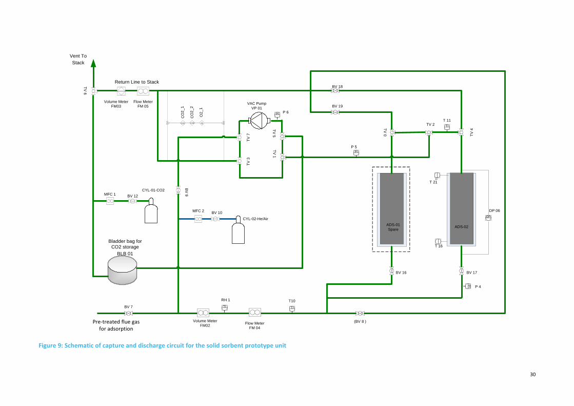
Figure 16: Computer screen shots of the control and monitoring system for solid sorbent CO2 capture
prototype unit. (a) Pre-treatment, (b) adsorption, (c) regeneration ............................................................... 38
Figure 17: Construction of solid sorbent prototype test unit with pre-treatment system (a) three test
unit frames (b) equipments being assembled on the frame. ........................................................................... 40
Figure 18: The fully constructed large scale honeycomb carbon fibre composite CO2 capture prototype
test unit at QCAT. ............................................................................................................................................. 40
Figure 19: Concrete basement with proposed location for solid sorbent prototype test unit at power
station ............................................................................................................................................................... 41
Figure 20: Photo of solid sorbent prototype CO2 capture test unit installed at the Power Station ................ 42
Figure 21: Photo of the constructed main flue gas supply and return lines from the flue duct ...................... 42
Figure 22: Photo of the inlet flue gas feed line connected to the solid sorbent test unit ............................... 43
Figure 23: Control room facility on-site located near the solid sorbent prototype test unit........................... 43
Figure 24: CO2 capture performance of solid sorbent prototype unit using simulated flue gas ..................... 45
Figure 25: CO2 capture performance of solid sorbent prototype unit using simulated flue gas during
cooling water circulation followed by pure CO2 flushing ................................................................................. 46
Figure 26: Performance of solid sorbent prototype unit during adsorption, CO2 flush and combined
thermal and vacuum regeneration steps ......................................................................................................... 47

11
Figure 27: Photo of the additional manual valves on the feed and return flue gas lines in between two
CSIRO’s CO2 capture units at the Power Station .............................................................................................. 48
Figure 28: Photo of the four channel hazardous gas detector installed on the solid sorbent test facility ...... 48
Figure 29: Opening of inlet flue gas pipeline on-site to provide flue gas to the solid sorbent test unit .......... 49
Figure 30: Process sequence procedure for the solid sorbent CO2 capture and regeneration testing ........... 50
Figure 31: Individual analysers for measuring SO2, NOx and CO used for the solid sorbent CO2 capture
site trial ............................................................................................................................................................. 51
Figure 32: Concentration profile of flue gas at the inlet and outlet of caustic scrubber column .................... 52
Figure 33: CO2 concentration profile during capture and regeneration process with flue gas pre-
treatment ......................................................................................................................................................... 53
Figure 34: Gas concentration profiles for solid sorbent CO2 capture and regeneration process with flue
gas pre-treatment............................................................................................................................................. 54
Figure 35: Gas concentration profiles for solid sorbent CO2 capture and regeneration process with flue
gas pre-treatment............................................................................................................................................. 55
Figure 36: Photo showing the gas leaking from the adsorption column ......................................................... 55
Figure 37: Photo of column resealing with high temperature epoxy sealant .................................................. 56
Figure 38: Photos of deformed adhesive material at the top and bottom of the column .............................. 57
Figure 39: Sketch of redesigned regeneration section of the column ............................................................. 57
Figure 40: Photo of the dismantled adsorption column from the prototype test unit .................................... 57
Figure 41: Photos of the repair work carried out on the adsorption column .................................................. 58
Figure 42: Photos of column leak test performed at the workshop ................................................................ 58
Figure 43: Photo of the redesigned regeneration set-up with welding of regeneration tubes at the top of
the adsorbent column ...................................................................................................................................... 59
Figure 44: Performance and stability of carbon composite solid sorbents ...................................................... 60

12
List of Tables
Table 1: Timelines for the completion of various project milestones .............................................................. 15
Table 2: Analysis of literature for carbon adsorbents used for CO2 capture from flue gas ............................. 24
Table 3: Characteristics of raw flue gas ............................................................................................................ 27
Table 4: Properties of coal used ....................................................................................................................... 27
Table 5: Predicted temperatures of gas and liquid around the wash column ................................................. 33
Table 6: Specifications of the equipments used in the pre-treatment system ................................................ 34
Table 7: List of activities and working sequence for the solid sorbent test unit construction ........................ 39
Table 8: Experimental plan for CO2 capture site trials with two different scenarios ....................................... 50
Table 9: Statistics of the site trial studies ......................................................................................................... 59
Table 10: Sequential description of one cycle of CO2 capture process involving two columns and five-
stage operations ............................................................................................................................................... 62
Table 11: Parameters used for the HYSYS process simulation ......................................................................... 63

13
1 Introduction
1.1 Background
In 2012, Australia’s emissions were 555 MtCO2-e, and electricity generation contributed just over one-third
of total emissions (193 MtCO2-e) [1]. NSW emissions in 2010 were 157 million tonnes CO2-e, and nearly half
of all NSW emissions in 2010 were from the stationary energy sector, primarily from public electricity
production. Coal combustion alone produces 62 million tonnes of emissions annually or nearly 40 per cent
of all NSW greenhouse gas emissions [2].
Growing concerns for global warming and climate change has attracted widespread efforts to develop
efficient and cost-effective technologies for Post-combustion CO2 Capture (PCC) from large point sources,
such as coal-fired power plants. Post-combustion carbon capture has the greatest near-term potential for
reducing emissions and can be retrofitted to existing coal-fired power plant infrastructure without requiring
substantial changes to the combustion process. Among various PCC technologies for CO2 capture from flue
gas, use of porous solid sorbents offers a promising solution as it has the potential to be highly cost-
effective and has less impact on the environment.
From January 2006, CSIRO began to develop the new CO2 capture process by developing nano-structured
monolithic carbon fibre composite adsorbents, which are fabricated in a honeycomb structure. This
structure enables CO2 capture in a dry process in dusty environments with low pressure drop. Hence, our
process based on solid carbon adsorbents is advantageous over the solvent process in the following
aspects:
- There are no degradation issues and secondary emissions using carbon adsorbents unlike amine
process, and therefore the solid sorbent process is more environmentally friendly.
- The carbon composite adsorbents have very high resistance to NOx and SOx in the flue gas from
coal fired power station, and our process could avoid the flue gas pre-treatment prior to CO2
capture, thereby avoiding the expensive facilities (e.g. flue gas de-nitrification, flue gas de-
sulphurisation) required to clean up the flue gas before it enters the CO2 capture unit. This is a very
important factor for coal fired power stations in Australia as there are no de-sulphurisation and flue
gas de-nitrification facilities.
- It is a dry process. No large volumes of waste water and sludge are produced from the process.
- The energy efficiency is expected to be high. In other words, energy penalty for CO2 capture is low
mainly due to:
o The open monolith structure leading to a low pressure drop through the adsorption column;
consequently the operational power consumption is low.
o This material possesses very high thermal conductivity and hence waste heat of the flue gas at
120-160oC can be used for CO2 desorption or in a combination with vacuum swing. Hence, no
high quality energy will be extracted from the coal fired power stations.
o This novel CO2 capture process is carried out at room temperature and atmospheric pressure,
so almost no energy is required for chilling and compression.
The State of the Art review of post combustion CO2 capture by using solid adsorbents is presented in the
next Chapter. The honeycomb shaped nano-structured monolithic carbon fibre composite adsorbents
developed and patented by CSIRO have been demonstrated under laboratory test conditions to effectively
adsorb over 95% of CO2 from simulated flue gas with the pure component CO2 capture capacity of 0.2 g/g
at 0oC. With proper choice of carbon fibre type and fabrication conditions these honeycomb carbon fibre

14
adsorbents are tailor made to achieve a high portion of micropores less than 0.7nm, which are more
relevant to CO2 capture at coal fired post-combustion capture conditions (10-15% CO2 at 25°C). It has been
demonstrated that these carbon fibre composites are twice more effective than conventional activated
carbons in adsorbing CO2 [3]. The higher the adsorption capacity is, the lesser the energy required for the
regeneration in terms of per unit of captured CO2, smaller the footprint of the PCC plant, and lower the
capital and operating costs.
1.2 Technology description
Since 2008, large sized carbon fibre composites and the large scale CO2 adsorption coupled with
regeneration test unit have been designed and developed (Figure 1a and b) to evaluate CO2 capture
performance using simulated flue gas with a maximum throughput of 200 L/min. Under laboratory test
conditions, experimental results have shown these carbon fibre composites can effectively adsorb over
97% of CO2 from simulated flue gas. Carbon dioxide capture or adsorption was performed at ambient
conditions at a flue gas temperature of 25⁰C and atmospheric pressure. Regeneration or desorption is
carried out by applying heat and vacuum. The waste heat from the flue gas can be utilised for the thermal
regeneration of sorbents at about 110-120⁰C. It has been demonstrated, under laboratory conditions that
combined thermal and vacuum swing regeneration of these materials, after adsorption, have produced
desorbed CO2 gas quality of up to 100% with overall capture efficiency of over 95%. Portion of the CO2
product is used to purge the adsorbents before desorption so as to enrich the CO2 concentration during
regeneration.
(a) Adsorbent (b) large scale test unit
Figure 1: Large scale CO2 capture adsorbent and adsorption and regeneration test unit
1.3 Scope of this project
In 2011, the Coal Innovation NSW (CINSW) awarded the project of Delta CO2 capture site trials to CSIRO, to
evaluate the performance of large size novel honeycomb carbon fibre composite adsorbents with actual
flue gas. This carbon composite site trial and demonstration project was carried out at Delta Electricity
power station. The large scale solid sorbent CO2 capture-regeneration prototype unit, designed and built by
CSIRO, was modified and then installed (besides another pilot plant unit using ammonia absorption
process) at the power station site. Two main experimental scenarios were planned for testing. First, to
conduct CO2 adsorption and desorption tests using pre-treated flue gas. Pre-treatment of flue gas includes
removal of SOx and particulates. Second set of study was to use the flue gas with minor pre-treatment, i.e.,
removal of particulates alone and no SOx and NOx removal. The originally proposed scope of the project
was to test the performance of the solid honeycomb monolithic adsorbents at power station using the pre-
treated flue gas obtained from the aqueous ammonia pilot plant. However, due to rescheduling of the time

15
lines of the aqueous ammonia pilot unit relocation, the overall scope of this project was expanded and the
time lines for the completion of project milestones were extended by two Quarters. The overall scope of
the project is given below and the rescheduled timelines of the project milestones are given in Table 1.
- Design and construct a dedicated pre-treatment system to remove SO2, NO2 and dust to treat the
real flue gas from the stack before entering the solid sorbents column for CO2 capture.
- Carryout modifications to the existing large scale CO2 capture system to suit operation with the flue
gas available under site conditions.
- Conduct experiments as planned to test the effect of actual flue gas characteristics on the
operation and performance of the CO2 capture unit and to demonstrate this new CO2 capture
process at the power station site.
- Obtain operational performance data and experience, which will be used for further scale up of a
pilot scale CO2 capture plant.
Table 1: Timelines for the completion of various project milestones
No. Timelines Milestone
1 Q1, 2011 Execution of Agreement
2 Q2, 2011 Complete power station site investigation and project plan.
3 Q4, 2011 Complete site infrastructure design
4 Q1, 2012 Begin site infrastructure construction;
5 Q2, 2012 Complete site infrastructure construction; prototype unit
transported to power station site
6 Q3, 2012 Complete installation of prototype unit at the site.
Submission of Year 1 Annual Progress Report
7 Q2, 2013 Commission prototype unit; commence site trials and
prototype unit demonstration
8 Q3, 2013 Commence data processing and analysis.
9 Q4, 2013 Complete site trials and prototype unit demonstration
10 Q1, 2014 Complete data processing and analysis; complete final
project report including GHG LCA

16
2 State of the Art
2.1 Basic routes for CO2 capture
Among the greenhouse gases CO2 is the largest contributor to global warming. It is emitted into the
atmosphere from various sources, mainly from the combustion of fossil fuels used in power generation,
transportation and industrial processes. As the demand for electricity is projected to increase both in
developed and developing countries, power generation will account for almost half the increase in global
emissions between 2000 and 2030 [4]. On the other hand, Canadell et al. [5,6] have reported a declining
trend in the long-term efficiency of the natural sinks in absorbing atmospheric CO2 , with major implications
for current and future growth of atmospheric CO2. With fossil fuels as the primary source of energy
(meeting over 90% of the increase in demand to 2030) for a foreseeable future [7,8], concerted action is
necessary in order to stabilise the atmospheric level of CO2. CO2 capture and storage (CCS) have been
receiving significant attention in recent years and are being recognized as promising options for CO2
emission reductions [9].
Generally speaking, there are three basic CO2 capture routes [10,11,12,13,14,15]: (1) pre-combustion
capture (via oxygen-blown gasification) (e.g. integrated gasification combined cycle technology); (2) oxy-
fuel combustion, i.e. removing nitrogen before combustion (e.g. oxy-fuel gas turbine technology); and (3)
post combustion capture, i.e. capturing CO2 from flue gas. Figure 2 illustrates the three basic CO2 capture
routes.
Figure 2: Three basic routes of CO2 capture
Pre-combustion capture involves reacting a fuel with oxygen or air and in some cases with steam or CO2 to
produce a gas mainly composed of carbon monoxide and hydrogen, which is known as synthesis gas
(syngas) or fuel gas. In a gasification reactor, the amount of oxygen available inside the gasifier is carefully
controlled so that only a portion of the fuel burns completely. This ‘‘partial oxidation’’ process provides the
heat necessary to chemically decompose the fuel and produce syngas. The carbon monoxide formed is
reacted with steam in a catalytic reactor, called a shift converter, to give CO2 and more hydrogen. CO2 is
then separated, usually by a physical or chemical absorption process, resulting in a hydrogen-rich fuel
which can be used in many applications, such as furnaces, gas turbines, engines and fuel cells. This route

17
needs long-term development in a number of enabling technical areas including syngas cleaning, gas
separation, hydrogen turbine and fuel cells to achieve targeted efficiency towards a hydrogen economy.
In oxy fuel combustion, nearly pure oxygen is used for combustion instead of ambient air, thereby
eliminating nitrogen and this results in a flue gas that is mainly CO2 and H2O. If fuel is burnt in pure oxygen,
the flame temperature is excessively high, but CO2 and/or H2O-rich flue gas can be recycled to the
combustor to lower the flame temperature. Oxygen is usually produced by low temperature (cryogenic) air
separation [16,17], and novel techniques to supply oxygen to the fuel, such as membranes (e.g. oxygen
permeable ceramic membranes) have been researched [18,19,20,21]. The major disadvantages of oxy-fuel
combustion are the high capital cost and large electric power requirement inherent in conventional
cryogenic air separation units required to produce oxygen. Chemical looping cycles [22] are being
investigated as an alternative means.
The principle of post combustion capture is to remove CO2 from flue gas after combustion. Instead of being
discharged directly to the atmosphere, flue gas is passed through equipment which separates/captures
most of the CO2. Adopting the post combustion capture route avoids the potentially long development
times required to develop cost-effective coal-derived syngas separation technologies, hydrogen turbine
technology, and fuel-cell technology etc. In particular, post combustion capture eliminates the need for
substantial modifications to the combustion process and provides a means for near-term CO2 capture for
new and existing stationary fossil fuel-fired power plants. It has been suggested that the major bulk (two-
thirds) of the cost involved in carbon sequestration process is the cost of CO2 capture [23].
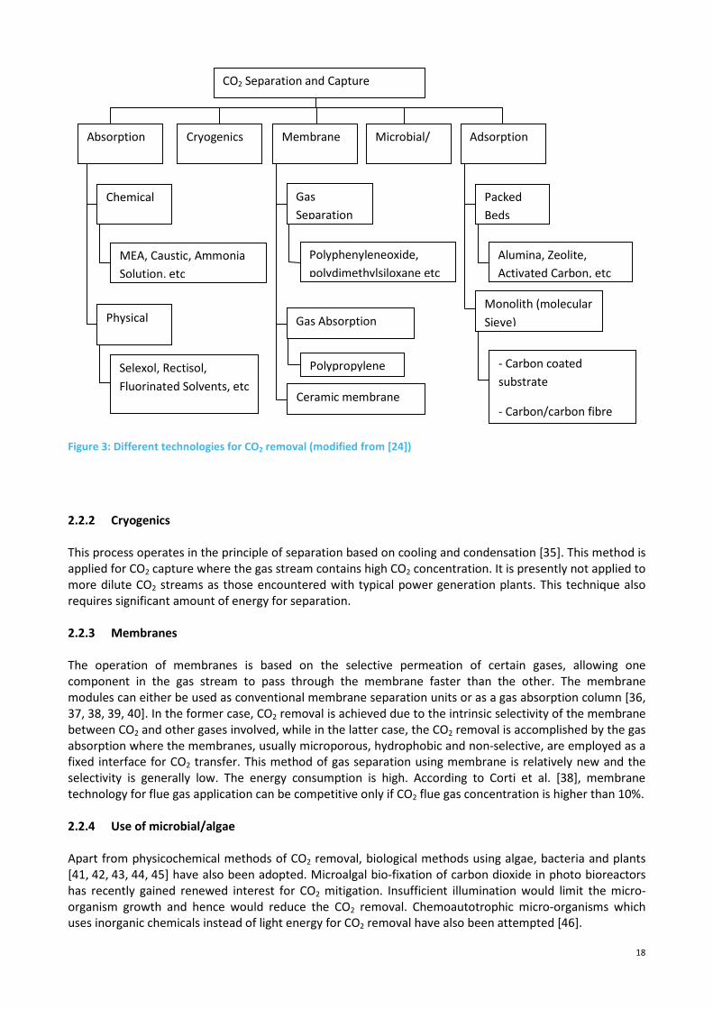
2.2 Post combustion CO2 capture technologies
To date, there are several post combustion gas separation and capture technologies being investigated
[24], namely; (a) absorption, (b) cryogenic separation, (c) membrane separation, (d) micro algal bio-fixation,
and (e) adsorption. Figure 3 summarizes various technology options for post combustion CO2 capture.
2.2.1 Absorption (i.e. solvent scrubbing)
This is a wellestablished CO2 capture system primarily used in the chemical and oil industries. Physical
absorption is temperature and pressure dependent with absorption occurring at high pressures and low
temperatures. These processes are used when the partial pressure of CO2 is high (>525 kPa). For lower CO2
concentrations, chemical absorption is more widely applied. Chemical absorption of CO2 from gaseous
streams such as flue gases depends on acid-base neutralization reactions using basic solvents [25,26]. The
preferred solvents for CO2 removal for post combustion capture are amines (e.g. monoethanolamine MEA)
[27,28] and ammonia solution [29,30], and for pre-combustion CO2 capture Selexol (dimethylethers of
polyetheleneglycol) [31], Rectisol (chilled methanol) [32], fluorinated solvents [33] etc are used. The
exhaust gas is first cooled, then treated to remove particulates and other impurities before being fed to the
absorption column, where the amine solvent absorbs CO2 by chemical reaction. The CO2-rich solution is fed
into a stripper column where the temperature is increased (to about 120°C) in order to release the CO2. The
released CO2 is compressed and the regenerated absorbent solution is recycled to the absorption column.
Absorption based processes for CO2 capture are closest to being commercialised. However, the solutions
are corrosive, produce chemical by-products and are energy intensive due to large thermal losses in the
absorption process [34].
18
Figure 3: Different technologies for CO2 removal (modified from [24])
2.2.2 Cryogenics
This process operates in the principle of separation based on cooling and condensation [35]. This method is
applied for CO2 capture where the gas stream contains high CO2 concentration. It is presently not applied to
more dilute CO2 streams as those encountered with typical power generation plants. This technique also
requires significant amount of energy for separation.
2.2.3 Membranes
The operation of membranes is based on the selective permeation of certain gases, allowing one
component in the gas stream to pass through the membrane faster than the other. The membrane
modules can either be used as conventional membrane separation units or as a gas absorption column [36,
37, 38, 39, 40]. In the former case, CO2 removal is achieved due to the intrinsic selectivity of the membrane
between CO2 and other gases involved, while in the latter case, the CO2 removal is accomplished by the gas
absorption where the membranes, usually microporous, hydrophobic and non-selective, are employed as a
fixed interface for CO2 transfer. This method of gas separation using membrane is relatively new and the
selectivity is generally low. The energy consumption is high. According to Corti et al. [38], membrane
technology for flue gas application can be competitive only if CO2 flue gas concentration is higher than 10%.
2.2.4 Use of microbial/algae
Apart from physicochemical methods of CO2 removal, biological methods using algae, bacteria and plants
[41, 42, 43, 44, 45] have also been adopted. Microalgal bio-fixation of carbon dioxide in photo bioreactors
has recently gained renewed interest for CO2 mitigation. Insufficient illumination would limit the micro-
organism growth and hence would reduce the CO2 removal. Chemoautotrophic micro-organisms which
uses inorganic chemicals instead of light energy for CO2 removal have also been attempted [46].
CO2 Separation and Capture
Absorption Cryogenics Membrane
Chemical
MEA, Caustic, Ammonia
Solution, etc
Microbial/
Algae
Adsorption
Physical
Selexol, Rectisol,
Fluorinated Solvents, etc
Packed
Beds
Monolith (molecular
Sieve)
Alumina, Zeolite,
Activated Carbon, etc
- Carbon coated
substrate
- Carbon/carbon fibre
Gas
Separation
Gas Absorption
Polyphenyleneoxide,
polydimethylsiloxane etc
Polypropylene
Ceramic membrane

19
2.2.5 Adsorption
Adsorbents development for CO2 capture can be classified broadly based on two main adsorption
mechanisms: Physical adsorption and chemical adsorption [47, 48, 49, 50]. In physisorption gas molecules
are adsorbed on the pore surface of the adsorbent due to weak electrostatic van der Waals forces, where
as in chemisorption, target gas molecules undergo chemical reaction to bind to the sorbents. In
physisorption the sorbents are generally stable even over 200°C, while chemisorbents tend to degrade over
120°C. Also, chemisorbents can permanently bind certain species thereby decreasing the capacity of
sorbents. Our focus on the solid sorbents for post combustion CO2 capture application has been on
physisorbents.
A variety of solid physical adsorbents such as activated carbons [51, 52, 53, 54], zeolites [55, 56, 57] and
mesoporous silicates [58], alumina [59, 60] metal oxides framework [61,62] have been extensively
investigated for CO2 separation. To be competitive with other available technologies, solid sorbents must
offer substantially greater adsorption capacities and selectivity for CO2 than currently available physical
sorbents, be less sensitive to toxic materials like SOx, NOx and moisture in the gas stream, readily able to
be regenerated without compromising on the performance during repeated capture and discharge
operations and possess good thermal and mechanical properties. Zeolite based adsorbents have been
extensively studied in CO2 separation processes next to activated carbon [63 64]. However, carbon based
adsorbents presents some key advantages over zeolites, such as hydrophobicity, significantly lower
adsorbent cost, lower energy for regeneration (lower isosteric heat of adsorption of CO2 for activated
carbon, which nearly half that of zeolite, means lower amount of energy needed for regeneration)[52, 65].
Comparing the estimates from the studies by Radosz et al. [66] and Ho et al. [67],the total capture cost of
US$27-44 per tonne of CO2 avoided using carbon adsorbents has been reported as compared to US$51 for
Zeolite adsorbents.
In a US DoE funded study [68, 69] over 100 different potential CO2 sorbents were evaluated. The adsorbent
materials were highly varied in their chemical and physical properties, and divided into three categories:
carbon based, amine supported materials and zeolites. They were tested under the same conditions
including using real flue gas of 10-12% CO2, saturated moisture (90% relative humidity), 5-6% O2, 100-
120ppm NOx, and 50-250ppm SO2. The study identified that carbon-based materials showed a working CO2
capacity between 0.3 to 1.1 wt% both in the laboratory and in the field conditions with superior
repeatability and stability. The supported amine based sorbents had a higher working CO2 capacity
between 1.3 to 7.5 wt%, but showed degradation in the field conditions. Zeolites had up to 1.6 wt% CO2
capacity, but its performance degraded quickly by the presence of moisture. In summary, carbon-based
sorbents had a low CO2 capacity, but exhibit superior cyclic stability and a resistance to poisoning by flue
gas constituents. Supported amines had exhibited high CO2 capacities and low theoretical regeneration
energies, but they were not cyclically stable and can be negatively affected by flue gas constituents.
Zeolites showed an extreme affinity to moisture that makes their use for CO2 capture unlikely. In another
study, a synergistic negative effect on CO2 adsorption by zeolite material was noticed due to the presence
of water and SO2 [70].
2.3 Carbon composite adsorbents for CO2 capture
2.3.1 Developments on carbon composite adsorbents
Over the last 15 years several researchers have attempted to make the activated carbon materials in
monolithic composite type to improve adsorption capacity [71, 72 ]. A composite adsorbent is a
heterogeneous combination of two or more materials (reinforcement material and resin binders), differing
in form or composition and their combination results in a material that has properties that cannot be
achieved with either of constituents acting alone. They can be made in many shapes including cylindrical,

20
flat plate or block shaped [73] or structured channel opening also known as honeycomb structures [3].
Activated carbon pellets or milled activated carbon powders or carbon precursors (e.g. phenolic resins)
mixed with binders or fillers or others have been fabricated (extrusion) into composites of desired shapes
[74,75]. Honeycomb structure refers to any structure having a plurality of openings or passages of any
desired size or shape extending all through the composite (as flow through channels). Introduction of a
honeycomb shaped carbon fibre composite adsorbents not only allow distribution of the process fluid
through a plurality of flow-through channels with minimal channel blocking, but also enable uniform
carbonisation and activation during the adsorbent fabrication. This shape is known to have a very high
geometric surface area to volume ratio [76]. Structured porous monolith materials made from carbon
fibres, which have the ability to selectively adsorb gases due to its molecular sieving characteristics, have
been investigated [77, 78, 79, 80, 81, 82, 83, 84, 85, 76, 86]. More recently, carbon fibre composites have
been investigated as adsorbents for gas separation and storage [3, 76, 85, 86, 87]. Carbon fibre composite
in monolith form reduce the interparticle voids and maximize bulk density, thereby increasing the
adsorption capacity of the material. These carbon fibre monolith adsorbents have a large portion of
micropores depending on the pyrolysis and activation steps involved in the manufacturing process. The
molecular sieving ability of these carbonaceous adsorbents can be controlled during their fabrication
process to make them be preferential to a gas (e.g. CO2) adsorption based on the difference in the shape
and size of the adsorbing molecule.
For example, US Pat. No. 6,030,698 to Burchell et al. [88] describes the manufacture of carbon fibre
composite molecular sieve (CFCMS) material from pitch based carbon fibre and phenolic resin. The
composite material is vacuum moulded into a plate (or cylinder) shape. Klett and Burchell [89] prepared a
carbon fibre composite material as a flat plate (12 inches length, 12 inches width and 2 inches thickness)
using polyacrylonitril (PAN) based fibre and phenolic resin. US Patent No. 5925168 to Judkins et al. [90]
indicates that the composite characteristics like strength, thermal conductivity, pore size distribution,
density and electrical properties can be modified or controlled with the appropriate carbon fibre or blend
of carbon fibres. US Patent No. 6090477 to Burchell et al. [91] describes the use of two types of pitch based
carbon fibres (isotropic and mesophase), to enhance the thermal conductivity of the monolith. The bulk
(typically cylindrical) or flat plate carbon (fibre) monoliths have been formed with carbonizable binding
materials and subsequently dried, cured, carbonised and activated. The formed monolithic material is quite
porous, and can therefore be used for adsorbing a component or components from a fluid by passing the
fluid through the monolith. However, this type of structure has several problems, in particular, a high
pressure drop across the monolith. In addition, these monoliths also have a tendency for the pores to
become blocked, should there be any dust or other particular matter in the fluid passing through the
monolith. Both of the above problems tend to lead to a reduction in the efficiency of the monolith.
Another type of the structured honeycomb monoliths comprises of substrate coating or impregnation with
carbon materials which are subsequently dried, cured, carbonised and activated. Since about 1980, more
than 90 % of the monoliths use substrates, which are made from ceramic material, cordite [92,93,94]. A
major disadvantage of ceramic supports is their high cost. Monolith materials also use various metal
substrates. However, base metals are more susceptible to loss of performance through poisoning by
sulphur, trace lead etc. In addition, the carbon coating may erode from the substrate, creating uneven
surfaces inside the monolith which can lead to blockages [95, 96, 97, 98, 99, 100, 101].
To develop more efficient high performance adsorbents to capture CO2, CSIRO devised the honeycomb
shaped nano-structured monolithic carbon fibre composite adsorbents, and these carbon fibre composites
are twice more effective than conventional activated carbons in adsorbing CO2 as compared in Figure 4 [3].
In the past a few years CSIRO has made a continuous effort, and made further significant progress in
developing new generation carbon composites using carbon nanotubes (CNT) modified carbon fibre
composites [102] and macadamia nutshell (MNS) derived biomass carbon composites [103]. Both the CNT
and MNS based carbon composites have shown further enhancement in CO2 adsorption capacities (at 25°C
and 1 atm) compared to originally developed carbon fibre composite adsorbents (Figure 5). Further
improvements in CO2 adsorption capacities with these new carbon composites, offer great potential for
their application in the post-combustion CO2 capture.

21
Figure 4: Comparison of CO2 adsorption performances between CSIRO developed carbon fibre composite and
activated carbon pellets
Figure 5: Advancement in carbon based composites performance with improved CO2 adsorption capacities
0
0.5
1
1.5
2
2.5
3
0 100 200 300 400 500 600 700 800
CO
2a
dso
rbe
d,
mm
ole
/g
Pressure, mmHg
Carbon fibre composites
Commercial activated carbon
0
0.5
1
1.5
2
2.5
3
3.5
4
0 100 200 300 400 500 600 700 800
CO
2a
dso
rbe
d,
mm
ole
/g
Pressure, mmHg
CNT composites
Carbon fibre composites
Macadamia nutshell composites
22
To the best of our knowledge, the CO2 adsorption capacities achieved by CSIRO composites are among the
highest, compared to other porous carbon based solid adsorbents in the world that are produced by
physically activation. Physical activation is normally carried out by heating the adsorbents using steam or
CO2, after carbonisation. Chemical activation is generally carried out using various activation agents or
chemicals like ZnCl2, KOH, K2CO3 etc [104]. Although some chemically activated carbon adsorbents have
reported higher CO2 adsorption capacities at saturation pressure (760 mm Hg and ambient temperature
298 K) [105,106], at pressures of 114 mmHg (corresponding to 15% of CO2), which are of more relevance
for flue gas applications, CSIRO composites have found to have very high CO2 adsorption capacities.
Moreover, chemical activation method is an expensive and complex process, requiring additional steps for
washing to remove residual inorganic material, which causes secondary problems of pollution, where as
physical activation is simple, environmentally benign, provide better control of micropore formation and
more suitable for carbon adsorbents [107]. So our focus of research on carbon composite adsorbent
development is by fabrication using physical activation.
2.3.2 Types of CO2 capture adsorbers using carbon adsorbents
Gas adsorption is a cyclical continuous operation involving multiple beds in which at least one bed remains
active with capture mode whilst the others are in regeneration mode by either the temperature swing
(TSA) or the pressure swing (PSA) or vacuum swing (VSA) methods [47]. In TSA, adsorption is carried out at
atmospheric pressure and the regeneration is achieved by heating the adsorbents using hot air or steam.
Similar to TSA, electric swing adsorption (ESA) is referred to that the solid sorbents are heated by the Joule
effect of applying electricity to the sorbents [108]. In PSA, adsorption is performed at pressures higher than
atmospheric pressure, while desorption is performed at atmospheric pressure. In VSA, adsorption operates
at atmospheric pressure and ambient temperature and desorption operates at lower pressures. In a post-
combustion application, the flue gas would pass through a bed of solid sorbents and the CO2 would be
preferentially adsorbed. The regeneration energy requirement for CO2 capture using dry solid adsorbents is
significantly reduced compared to the aqueous amine-based process because of the absence of large
amount of water [109].
The adsorption process used for solid sorbents for CO2 capture from flue gas can be broadly differentiated
as fixed bed, moving bed and honeycomb. Fixed bed or packed bed adsorbers are by far the most
commonly used adsorption system, using adsorbents like activated carbon pellets packed in reactor vessels.
In a fixed bed adsorption system, the feed gas generally flows downwards (as upward flow would result in
fluidisation of fine sorbents) through the stationary adsorbent packing. For the conventional packed bed
reactors, the inherent limitations, such as, high pressure drop, low mass and heat transfer characteristics,
are not favourable for its application in the post combustion CO2 capture. Due to the high pressure drop
associated with fixed bed and given the huge volume of flue gas, moving bed reactor operates with
adsorbent particles moving in the opposite direction as the gas while the gas flows either counter current
or across the sorbents. The adsorbent material circulates between adsorption section and regeneration
section. It provides greater mass transfer efficiency, as the adsorbents leave the adsorption section when it
is essentially at equilibrium with the feed gas. Fluidised bed is also one form of moving bed reactor where
the gas moves upwards and the sorbent enters at the top of the bed and leaves the adsorber in the bottom
of the bed. Honeycomb structure refers to the unit having a plurality or matrix of openings or passages of
any desired size or shape extending all through the material (as flow through parallel channels) and so the
drawbacks of the fixed bed adsorber are avoided. The structured honeycomb shaped adsorbents by their
nature are immobilized, so fluidisation of adsorbents is nonexistent. The honeycomb shaped adsorbents
are placed inside the reactor vessel with flue gas able to enter from the top or bottom of the reactor.
Generally flue gas enters from the bottom of the reactor and leaves from the top of the reactor. As the flue
gas pass through the adsorbent channels, the adsorbate from the bulk gas phase are adsorbed onto the
adsorbent surface. The honeycomb type reactors are more suited than fixed bed reactors for flue gas
application as it allows the use of dust laden flue gas at high flow rates without large pressure drop as it
pose minimum obstruction to particulate matter. It also provides greater geometric surface area (which
leads to better gas solid contact) and ease of scale-up compared to packed bed. Another important aspect

23
of the honeycomb carbon fibre composite adsorbents developed by CSIRO [110] is that the whole
adsorbent comprise of reactive carbon monolith, unlike other systems such as carbon coated honeycomb
material [111, 112], having inert substrate coated (about 10% of volume) with active material on the inner
walls of the channel, which would result in gradual reduction in its performance.
2.3.3 Laboratory and site trials of CO2 capture using carbon adsorbents
Table 2 provides an overview of available literature of carbon based adsorbents studied for CO2 capture
from flue gas. As it can be seen from the Table 2, to our best of our knowledge for carbon adsorbents, so
far studies have been carried out only using simulated flue gas and under laboratory conditions. Only one
study by Wang et al. [113] a site trial at the power station was carried out with activated carbon. However,
the CO2 concentration in the flue gas to the activated carbon adsorbent was 70-80% and was not subjected
to actual flue gas conditions. Experiences from actual site trial studies are very critical for the development
of the solid sorbent CO2 capture technology. A number of large-scale demonstration plants (equipped with
a capture capacity of 1 MtCO2/year) for the post-combustion capture of CO2 from coal-fired power plants
planned for operation in the next decade are solvent based [114].
To our knowledge, this carbon fibre composite solid sorbent site trial and prototype unit demonstration for
CO2 capture from real coal fired station flue gas using a combined thermal and vacuum swing regeneration
is by far the first of its kind in the world. The developmental stage in the solid sorbent studies using
honeycomb carbon fibre composite for flue gas CO2 capture has already advanced ahead of other research
works with carbon based adsorbents around the world, as we have completed our evaluation of the
performance of these honeycomb carbon fibre composite solid sorbents under laboratory scale from 2006
to 2008 and under large scale using simulated flue gas between 2008-2011 and then with this site trial from
2011-2014 using real flue gas. The CSIRO devised honeycomb shaped carbon fibre composite adsorbents
are novel and exhibits unique features of high CO2 adsorption capacity, low pressure drop, good mechanical
properties, handle dust containing gas streams, thermally conductive and selective adsorption of gases. The
site trial studies aimed to provide information about the stability and performance of these carbon
composite adsorbents under actual field conditions subjected to real flue gas containing mixture of various
gas constituents for an extended period of time, which is very important for the development of this novel
CO2 capture technology.

24
Table 2: Analysis of literature for carbon adsorbents used for CO2 capture from flue gas
Adsorbent Type Scale/
Adsorber Type
Gas
composition
CO2 adsorption capacity Regeneration
Analysis
Condition mmole g
-1 Method
Max CO2
conc., %
Capture
efficiency, % Ref.
Pitch based
activated carbon
Lab Scale/fixed
bed
Simulated flue
gas, 15% CO2 in
N2
Pure CO2
@15kPa, 30°C 1.1
TSA, VSA-
ESA 75-80 76~100 115
Activated carbon Lab Scale/fixed
bed
Simulated flue
gas, 17% CO2 ,
79% N2, 4% O2
Pure CO2
@15kPa, 25°C 0.75 PSA 99.8 34 116
Norit activated
carbon
Lab Scale/fixed
bed
Simulated flue
gas, 17% CO2 in
N2
17 v% CO2, bal
N2, 30 oC
0.77
TSA
VSA
VTSA
43
40
87
97
52
Pitch based
activated carbon Field/ fixed bed
Enriched flue
gas 74.5% CO2
Pure CO2
@15kPa, 30°C 0.7 VPSA 95.6 90.2 113
Commercial
activated carbon
pellets
Lab Scale/fixed
bed
Simulated flue
gas, 15% CO2 in
N2
15 v% CO2, bal
N2, 47°C 0.09 - - - 70
Biomass Activated
carbon
Lab Scale/fixed
bed
Simulated flue
gas, 14% CO2 in
N2
Pure CO2
@15kPa, 25°C 1.02-1.08 - - - 51
Norit activated
carbon
Lab Scale/sound
assisted
fluidised bed
Simulated flue
gas, 15% CO2 in
N2
15 v% CO2, bal
N2, 25°C 0.37-0.55 - - - 117
CSIRO carbon
nanotube
composite
Lab scale/
Honeycomb
monolith fixed
bed
Simulated flue
gas, 12% CO2,
5% O2, bal N2
Pure CO2
@15kPa, 25°C 1.18 - - - 102
CSIRO carbon
fibre composite
Large scale/
Honeycomb
monolith fixed
bed
Simulated flue
gas, 13-15%
CO2, 5-6% O2,
bal N2
Pure CO2
@15kPa, 25°C 0.92 TSA & VSA ~100 96 110
25
3 Development of Site Test Facility
The major activities involved in the development of site test facility are listed below:
- Site investigation
- Design of the pre-treatment system
- Modifications to the existing large scale CO2 prototype unit
- Development of assembly design drawings
- Development of control and monitoring system for the site test unit
- Construction of pre-treatment system and integration with the CO2 capture unit
- Connection of the test unit to flue gas.
3.1 Site investigation
3.1.1 Plant layout
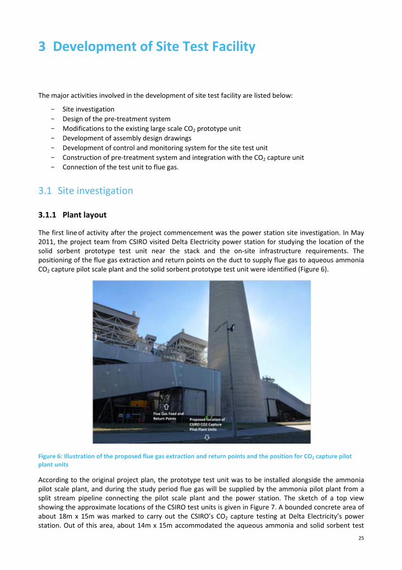
The first line of activity after the project commencement was the power station site investigation. In May
2011, the project team from CSIRO visited Delta Electricity power station for studying the location of the
solid sorbent prototype test unit near the stack and the on-site infrastructure requirements. The
positioning of the flue gas extraction and return points on the duct to supply flue gas to aqueous ammonia
CO2 capture pilot scale plant and the solid sorbent prototype test unit were identified (Figure 6).
Figure 6: Illustration of the proposed flue gas extraction and return points and the position for CO2 capture pilot
plant units
According to the original project plan, the prototype test unit was to be installed alongside the ammonia
pilot scale plant, and during the study period flue gas will be supplied by the ammonia pilot plant from a
split stream pipeline connecting the pilot scale plant and the power station. The sketch of a top view
showing the approximate locations of the CSIRO test units is given in Figure 7. A bounded concrete area of
about 18m x 15m was marked to carry out the CSIRO’s CO2 capture testing at Delta Electricity’s power
station. Out of this area, about 14m x 15m accommodated the aqueous ammonia and solid sorbent test
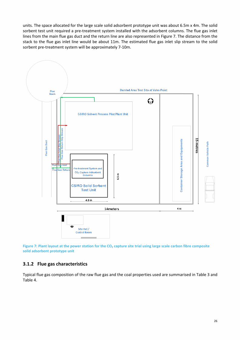
26
units. The space allocated for the large scale solid adsorbent prototype unit was about 6.5m x 4m. The solid
sorbent test unit required a pre-treatment system installed with the adsorbent columns. The flue gas inlet
lines from the main flue gas duct and the return line are also represented in Figure 7. The distance from the
stack to the flue gas inlet line would be about 11m. The estimated flue gas inlet slip stream to the solid
sorbent pre-treatment system will be approximately 7-10m.
Figure 7: Plant layout at the power station for the CO2 capture site trial using large scale carbon fibre composite
solid adsorbent prototype unit
3.1.2 Flue gas characteristics
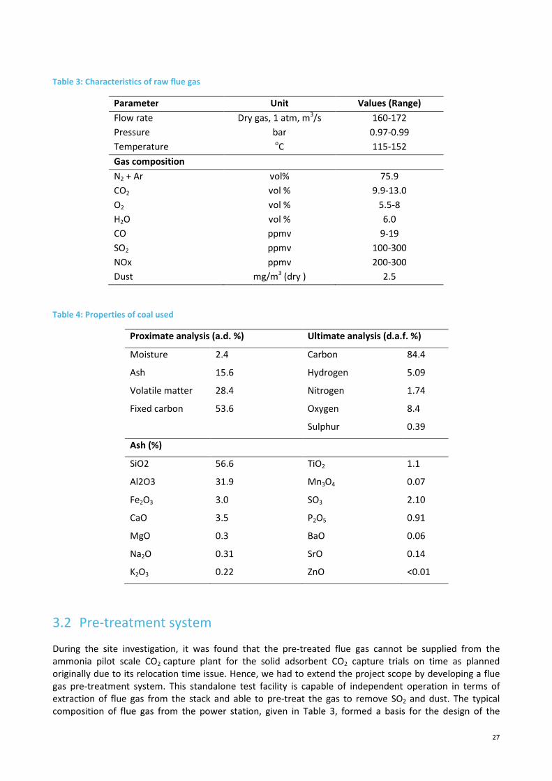
Typical flue gas composition of the raw flue gas and the coal properties used are summarised in Table 3 and
Table 4.
Co
nta
ine
r S
tora
ge A
rea
an
d E
qu
ipm
en
ts
15
me
tres
Flu
e G
as
In
let
Sli
p S
trea
m
Flu
e G
as
Re
turn
Slip
Str
eam
Co
mm
on
Ve
hic
le P
ath
Flu
e G
as
Du
ct
6.5
m
27
Table 3: Characteristics of raw flue gas
Parameter Unit Values (Range)
Flow rate Dry gas, 1 atm, m3/s 160-172
Pressure bar 0.97-0.99
Temperature oC 115-152
Gas composition
N2 + Ar vol% 75.9
CO2 vol % 9.9-13.0
O2 vol % 5.5-8
H2O vol % 6.0
CO ppmv 9-19
SO2 ppmv 100-300
NOx ppmv 200-300
Dust mg/m3 (dry ) 2.5
Table 4: Properties of coal used
Proximate analysis (a.d. %) Ultimate analysis (d.a.f. %)
Moisture 2.4 Carbon 84.4
Ash 15.6 Hydrogen 5.09
Volatile matter 28.4 Nitrogen 1.74
Fixed carbon 53.6 Oxygen 8.4
Sulphur 0.39
Ash (%)
SiO2 56.6 TiO2 1.1
Al2O3 31.9 Mn3O4 0.07
Fe2O3 3.0 SO3 2.10
CaO 3.5 P2O5 0.91
MgO 0.3 BaO 0.06
Na2O 0.31 SrO 0.14
K2O3 0.22 ZnO <0.01
3.2 Pre-treatment system
During the site investigation, it was found that the pre-treated flue gas cannot be supplied from the
ammonia pilot scale CO2 capture plant for the solid adsorbent CO2 capture trials on time as planned
originally due to its relocation time issue. Hence, we had to extend the project scope by developing a flue
gas pre-treatment system. This standalone test facility is capable of independent operation in terms of
extraction of flue gas from the stack and able to pre-treat the gas to remove SO2 and dust. The typical
composition of flue gas from the power station, given in Table 3, formed a basis for the design of the
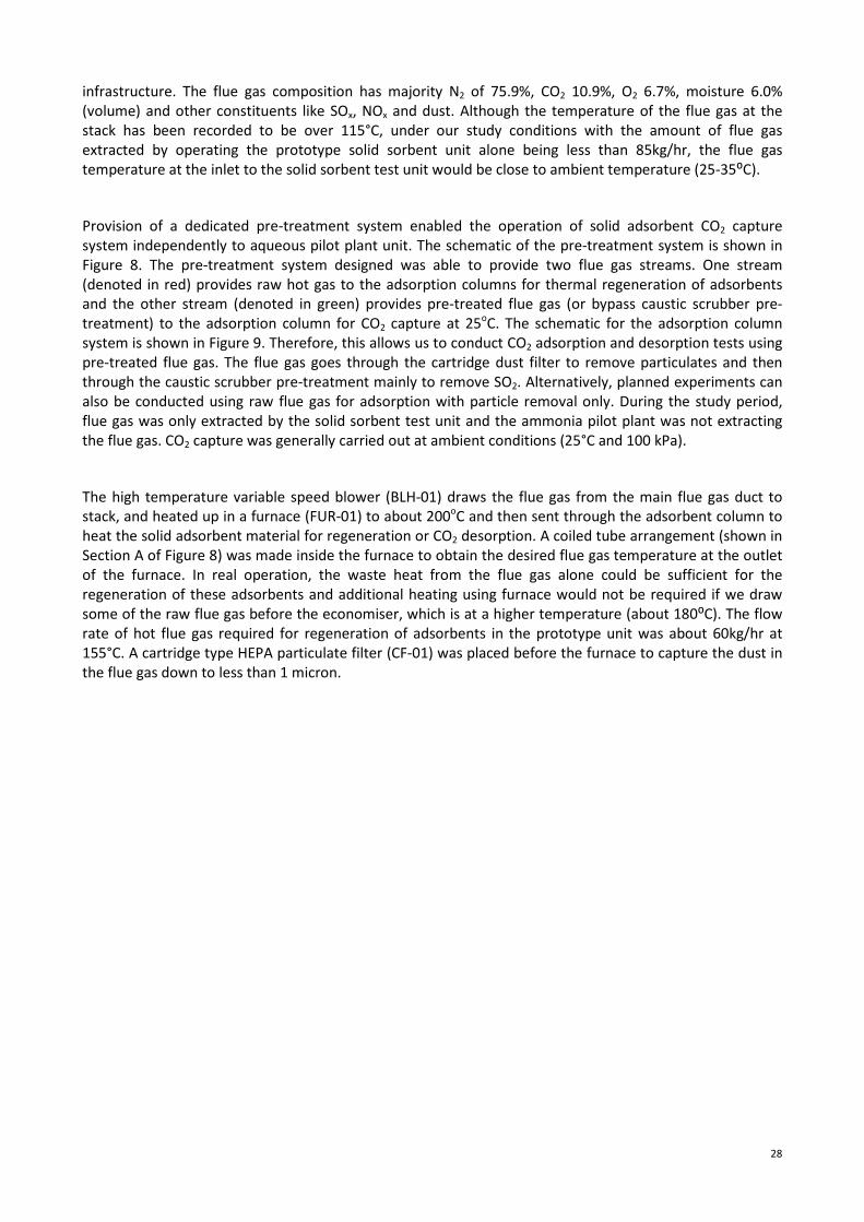
28
infrastructure. The flue gas composition has majority N2 of 75.9%, CO2 10.9%, O2 6.7%, moisture 6.0%
(volume) and other constituents like SOx, NOx and dust. Although the temperature of the flue gas at the
stack has been recorded to be over 115°C, under our study conditions with the amount of flue gas
extracted by operating the prototype solid sorbent unit alone being less than 85kg/hr, the flue gas
temperature at the inlet to the solid sorbent test unit would be close to ambient temperature (25-35⁰C).
Provision of a dedicated pre-treatment system enabled the operation of solid adsorbent CO2 capture
system independently to aqueous pilot plant unit. The schematic of the pre-treatment system is shown in
Figure 8. The pre-treatment system designed was able to provide two flue gas streams. One stream
(denoted in red) provides raw hot gas to the adsorption columns for thermal regeneration of adsorbents
and the other stream (denoted in green) provides pre-treated flue gas (or bypass caustic scrubber pre-
treatment) to the adsorption column for CO2 capture at 25oC. The schematic for the adsorption column
system is shown in Figure 9. Therefore, this allows us to conduct CO2 adsorption and desorption tests using
pre-treated flue gas. The flue gas goes through the cartridge dust filter to remove particulates and then
through the caustic scrubber pre-treatment mainly to remove SO2. Alternatively, planned experiments can
also be conducted using raw flue gas for adsorption with particle removal only. During the study period,
flue gas was only extracted by the solid sorbent test unit and the ammonia pilot plant was not extracting
the flue gas. CO2 capture was generally carried out at ambient conditions (25°C and 100 kPa).
The high temperature variable speed blower (BLH-01) draws the flue gas from the main flue gas duct to
stack, and heated up in a furnace (FUR-01) to about 200oC and then sent through the adsorbent column to
heat the solid adsorbent material for regeneration or CO2 desorption. A coiled tube arrangement (shown in
Section A of Figure 8) was made inside the furnace to obtain the desired flue gas temperature at the outlet
of the furnace. In real operation, the waste heat from the flue gas alone could be sufficient for the
regeneration of these adsorbents and additional heating using furnace would not be required if we draw
some of the raw flue gas before the economiser, which is at a higher temperature (about 180⁰C). The flow
rate of hot flue gas required for regeneration of adsorbents in the prototype unit was about 60kg/hr at
155°C. A cartridge type HEPA particulate filter (CF-01) was placed before the furnace to capture the dust in
the flue gas down to less than 1 micron.

29
Figure 8: Schematic of the flue gas pre-treatment system for Solid Sorbent CO2 Capture Prototype Unit
BV
4
T 1
P 1
TI
TI
DP
BV
1
T 1
7
(pH
1)
P 7
T 1
3
TI
TI
TI
Furn
ace
45
0m
m
30
Figure 9: Schematic of capture and discharge circuit for the solid sorbent prototype unit
CYL-02-He/Air
CYL-01-CO2
Vent To Stack
Pre-treated flue gas
for adsorptionFlow Meter
FM 04
MFC 2
Volume Meter FM02
Bladder bag for CO2 storage
BLB 01
VAC Pump VP 01
PI
DP
BV 16 BV 17
TV
1
TV
3
BV 12
TI
Return Line to Stack
DP 06
TV
0 TV
4
TV 2
TV
6
P 4
T 21
T 16
ADS-01Spare
ADS-02
CO2 CO2 O2
TV
5
PI P 6
TI
RH 1
BV
9
(BV 8 )
TI
T10
BV 10
BV 19
BV 18
TV
7
BV 7
MFC 1
TI
T 11
CO
2_1
CO
2_2
O2_
1
PI
P 5
Volume Meter FM03
Flow Meter FM 05

31
The other portion of the flue gas stream undergoing pre-treatment before being used for CO2 adsorption,
passes through single stage direct contact cooling (DCC) packed bed wash column (WC-01). The sketch of
the designed DCC column is shown in Figure 10. The DCC wash column was used mainly to remove SOx and
some NOx. The 2m long x 161mm dia (ID) column (316SS) consist of 0.75m pall rings (16mm SS) packing and
was operated by circulating a 1% caustic solution (counter current to flue gas) at a pH of ~9.0 to induce
good gas-liquid contact surface area. Demisting at the top of the wash column was carried with a stainless
steel fibre pad located above the packing. The pre-treated flue gas exited through the top section of the
column. Caustic or makeup water was added to the spent wash solution leaving the column from the
bottom to maintain the alkalinity of the solution to around pH9. The circulation pump (CP-01) fed the
caustic solution to the column. Periodic blow down of the caustic solution from the wash column reduced
the build-up of the particulates removed from flue gas, and nitrate and sulphate salts of sodium in the
solution. Heat exchanger (HE-01) was used to cool the spent caustic solution coming out from the column
before returning to the column for re-use. Cold water from the chiller (CHL-01) was passed through the
heat exchanger when required to remove the heat from the spent caustic solution. Representative
temperatures of flue gas and wash solutions predicted during the design phase at various locations around
the wash column as indicated in Figure 11 for the pre-treatment step are given in Table 5.
The chilled water flow rate of about 6 – 10 L/min through the heat exchanger and the column inlet flue gas
flow rate of 200 L/min were used to obtain the representative temperatures given in Table 5. The wash
column was designed to treat flue gas up to 350 L/min, although the adsorbent columns are designed for
processing up to 200 L/min flue gas, so as to provide an additional buffer capacity for the wash column. A
100L caustic holding tank was also provided in the circuit in addition to the storage sump at the bottom of
the wash column to ensure sufficient liquid flow through the system. As the CO2 adsorption capacity is
temperature dependent, the heat exchanger (HE-02) was included for fine adjustments of the feed flue gas
temperature to 25oC (if required) before it entered the adsorption column. A by-pass line to the wash
column was provided to evaluate the adsorption capacity of the adsorbents for the flue gas without SOx
and NOx removal. The wash column was designed to handle flue gas with inlet temperature of 120°C.
However, during actual operation, the flue gas temperature was at ambient temperature at the inlet to
scrubber column.
Parameters such as temperatures, pH, pressures, differential pressure across the wash column, flow rates
of gas and liquid, gas compositions at inlet and outlet of wash column were monitored during the
operation. Specifications of the various equipments used for the pre-treatment process are given in Table
6.

32
Figure 10: Sketch of single stage direct contact cooling (DCC) packed bed wash column
0.150 m

33
Figure 11: Schematic of the temperature and flow monitoring points around the wash column
Table 5: Predicted temperatures of gas and liquid around the wash column
Locations 1 2 3 4 5 6 7
Temperature, oC 120 15 18.7 18.7 15 10 13.7
(Note: Ambient temperature during actual operation at Location 1)
CP-01

34
Table 6: Specifications of the equipments used in the pre-treatment system
Equipments Code Specifications Pipng Details
High
Temperature
Blower
BLH-01 Single Stage, Volume throughput 100m3/hr, Max
pressure 6 kpa, operating temperature 180C, fan speed
2900 rpm++
Inlet ID: 150mm,
Outlet port:
84x84mm
Cartridge Filter CF-01 304SS Stainless Steel Housing, HEPA Filter Media,
Special gaskets to handle 175⁰C
38mm BSP
Furnace FUR-01 1000oC max, fully with control systems -
Wash Column WC-01 Design. Size: 150NB Shd 10 x 2.1 m high -
Wash Column
Internals
WCI-01 (1) 16mm Pall Rings with a packed bed depth of
750mm
(2) Pan type liquid distributor
(3) Random packing support plate
(4) Random packing retainer grid
(5) Demister pad
-
Heat Exchanger HE-01 Caustic cooler 316 ss plate heat exchanger 19.05mm BSP
Flue gas 316 ss plate heat exchanger 31.75mm BSP
Chiller CHL-01 Supply water temp 5°C 31.75mm BSP
Caustic
Circulation Pump
CP-01 Positive displacement pump, rate up to 25L/min 25.4mm BSP
3.3 Modifications to the existing large scale CO2 test unit
Modification to the existing large scale prototype unit was carried out to suit the added pre-treatment
setup. In the earlier design of the adsorption column for the large scale setup, regeneration of adsorbent or
CO2 desorption was carried out by passing the hot gas (or cooling water for cooling) through the hot air
channels (13 X 4.76mm SS tubes) through the cylindrical adsorbent (Figure 12). In order to enhance the
heat transfer performance in the prototype unit, the size of the hot air channels through the adsorbents
were enlarged (13 X 12.7 mm). High temperature viton o-rings were provided around the tubes where it
exited the top and bottom flanges, in order to prevent gas leakage from the adsorption column. Aluminium
plates with six bolts were introduced on the surface of top and bottom flanges of the column, which held
the o-rings in position (Figure 13). The adsorption column was leak tested up to 200 kPa to check the
sealing. The modifications to the hot air channels in the adsorbent column and the CO2 adsorption and
desorption pipelines integrating with pre-treatment system were carried out. During the site trials, the use
of the o-rings was not a good choice as the o-rings failed to seal the gas leaking after a number of trials, and
this issue will be discussed in Chapter 5.3.

35
Figure 12: Sketch of the adsorption column with the previous design of regeneration channels (Section A)
Figure 13: Modified regeneration tubes setup for the adsorption column in the prototype test unit
3.4 Design of site trial prototype test unit
Based on the design considerations, the CO2 capture prototype test unit assembly drawings (both 2D and
3D) were prepared using SolidWorks software. Drawing for the pre-treatment equipment layout (2D) on
the frame is shown in Figure 14. Overall test unit assembly drawing (3D) was also prepared as shown in
Figure 15. The cylindrical adsorption column will be used for this site trial project. For representation
purpose, a rectangular adsorption column that has been investigated separately for better heat transfer
through another CSIRO Research Project and is also shown in the unit assembly drawing. Individual pipe
work drawings for connecting each one of the equipments were also prepared. These drawings were used
for the construction of the test unit assembly.

36
Figure 14: Two dimensional drawing of the positioning of the pre-treatment equipments on the frame
Figure 15: View of the whole assembly of the Solid sorbent CO2 capture prototype unit

3.5 Control and monitoring s
CO2 capture and regeneration unit
from the computer. The operation of equipments such as blower, valves, flow meters etc and continuous
data logging of the readings from thermocouple, pressure transducers and gas sensors
through the control and monitoring
equipment during the tests were performed
overshoot of motor speed, temperature etc
were also provided to safely shutdown the system in case of any malfunctions.
control and monitoring system as seen in the computer during operation is shown in
the control monitoring system is divided into three sections, namely, pre
regeneration sections.
onitoring system
unit coupled with pre-treatment system was able to be
tion of equipments such as blower, valves, flow meters etc and continuous
data logging of the readings from thermocouple, pressure transducers and gas sensors
and monitoring system developed using LabVIEW interface. The operations of the
equipment during the tests were performed via the computer. Safety features such as protection for
overshoot of motor speed, temperature etc. were built into the control system. Emergency stop systems
also provided to safely shutdown the system in case of any malfunctions.
control and monitoring system as seen in the computer during operation is shown in
the control monitoring system is divided into three sections, namely, pre-treatment, adsorption and
(a)
37
was able to be remotely operated
tion of equipments such as blower, valves, flow meters etc and continuous
data logging of the readings from thermocouple, pressure transducers and gas sensors were carried out
. The operations of the
Safety features such as protection for
built into the control system. Emergency stop systems
also provided to safely shutdown the system in case of any malfunctions. The screen shot of the
control and monitoring system as seen in the computer during operation is shown in Figure 16. As shown,
treatment, adsorption and
Figure 16: Computer screen shots of the control and monitoring system for solid sorbent CO
unit. (a) Pre-treatment, (b) adsorption, (c) regeneration
(b)
(c)
Computer screen shots of the control and monitoring system for solid sorbent CO
treatment, (b) adsorption, (c) regeneration
38
Computer screen shots of the control and monitoring system for solid sorbent CO2 capture prototype

39
3.6 Construction of the CO2 capture prototype test facility
3.6.1 Assembly of the main body of test facility at CSIRO
Components to be purchased for the site infrastructure construction were determined and suitable
suppliers were identified and up to three quotations were obtained wherever possible to match with our
required specification at minimum cost. The scrubber wash column was fabricated to our design
requirements, to minimise the cost. Some of sensors, flow meters etc. were reutilised from some of our
previous test units.
A list of activities and work plan was prepared for the construction of solid sorbent prototype test unit with
pre-treatment system, as given in Table 7. At the start of the infrastructure construction work of solid
sorbent prototype test unit, CSIRO workshop personnel was assigned to construct the steel frame for the
equipments in the site trail prototype test unit and modify the adsorption column previously used in the
large scale setup to the required specifications of site trial prototype test unit. The steel frame construction
work was completed by a CSIRO mechanical technician.
Table 7: List of activities and working sequence for the solid sorbent test unit construction
Activities and Work Order
1. Construct frames for pre-treatment system according to drawings
2. Prepare existing frame to mount the cylindrical adsorption column
3. Connect flexible tubes to cylindrical column ends for regeneration fluids, install the
cylindrical column on the frame, construct and install the two regeneration fluid
distribution manifolds which connect to the column through the flexible tubes.
4. Secure various pre-treatment equipments to the frames according to the 2D drawings
5. Check suitable pipes, lengths, valves, fittings etc. to be connected to the equipments
according to the drawings. Flanges for the blower and cone sections, furnace coils,
flow meter, pipe side flange connection to the scrubber column are to be made.
6. Pipe works leading to the rectangular column must also be laid so that column can be
easily included into the system when required.
7. After pipeline installation, weld equipments on to the frame
8. Install thermocouples, sensors etc on the pipelines
9. Carry out pipe insulations
10. Safety rails, platforms, ladders to be mounted on the frames
11. Leak test to be performed for the entire system
Further on, due to unexpected resignation (without prior notification) of the CSIRO contract personnel, the
construction work was stopped until a suitable contractor was found to carry out this work. Two external
companies were approached and quotations were obtained. With the permission from the Coal Innovation
NSW, a contract agreement was prepared and relevant approvals within CSIRO were also obtained, to
undertake the infrastructure construction work with the selected external contractor. The assembly unit
construction work was then continued through the external contractor in Brisbane. The assembling of
various equipments such as blower, heat exchangers, furnace, dust filter, scrubber wash column etc on the
frame was carried out (Figure 17), according to the assembly drawings provided by CSIRO.

40
Figure 17: Construction of solid sorbent prototype test unit with pre-treatment system (a) three test unit frames (b)
equipments being assembled on the frame.
The construction work on the test unit assembly was carried out according to the list of activities provided
to the contractor by CSIRO. CSIRO team regularly visited the contractor’s workshop to monitor the progress
of work. The assembly work was completed in September 2012. While the prototype test unit was
constructed, the work on control and instrumentation for the system was simultaneously carried out by the
project team. After completion of test unit assembling, electrical work and control system were installed
and the whole unit was ready for transportation to the site. The photo of the fully constructed solid sorbent
prototype unit at QCAT, before transportation to the power station site, is shown in Figure 18.
Figure 18: The fully constructed large scale honeycomb carbon fibre composite CO2 capture prototype test unit at
QCAT.
3.6.2 Transportation of constructed solid sorbent prototype unit to site
The unit was pre-tested on some components (like checks on appropriate signals to designated transducers
etc) at CSIRO QCAT site before transporting it to the site. After obtaining quotations from two transport
companies, one of the transportation companies was chosen for transporting the constructed test unit to
(b) (a)
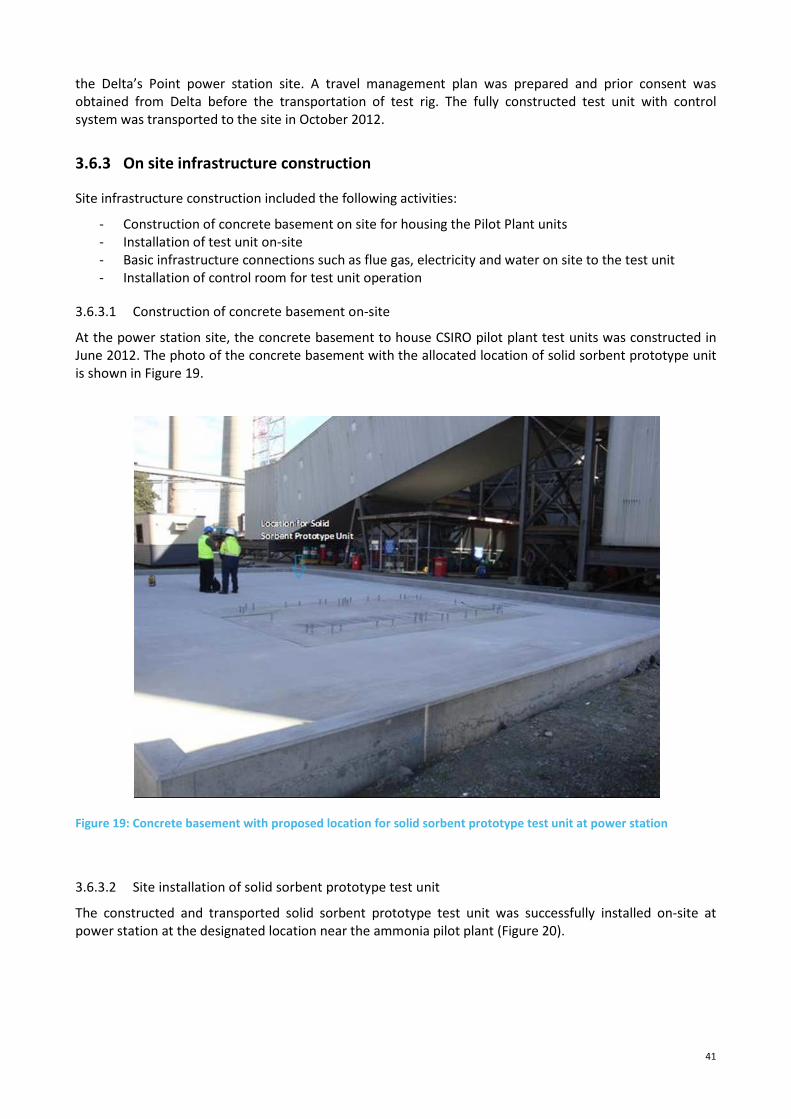
41
the Delta’s Point power station site. A travel management plan was prepared and prior consent was
obtained from Delta before the transportation of test rig. The fully constructed test unit with control
system was transported to the site in October 2012.
3.6.3 On site infrastructure construction
Site infrastructure construction included the following activities:
- Construction of concrete basement on site for housing the Pilot Plant units
- Installation of test unit on-site
- Basic infrastructure connections such as flue gas, electricity and water on site to the test unit
- Installation of control room for test unit operation
3.6.3.1 Construction of concrete basement on-site
At the power station site, the concrete basement to house CSIRO pilot plant test units was constructed in
June 2012. The photo of the concrete basement with the allocated location of solid sorbent prototype unit
is shown in Figure 19.
Figure 19: Concrete basement with proposed location for solid sorbent prototype test unit at power station
3.6.3.2 Site installation of solid sorbent prototype test unit
The constructed and transported solid sorbent prototype test unit was successfully installed on-site at
power station at the designated location near the ammonia pilot plant (Figure 20).

42
Figure 20: Photo of solid sorbent prototype CO2 capture test unit installed at the Power Station
3.6.3.3 On-site infrastructure connections to test unit
The operation of solid sorbent CO2 capture unit required basic infrastructure such as source flue gas for
testing, electrical power supply for the operation of instruments, water as part of thermal regeneration of
adsorbents and compressed air. Water and electricity connections to the test unit were provided by Delta
Electricity. Three phase power supply (60 amps), sufficient to operate all the components of the test unit,
was supplied and connected by Delta Electricity. Water chiller was installed near the solid sorbent test unit
to supply cold water for adsorbent cooling after thermal regeneration. Compressed air required to operate
the valves was obtained using the small compressor installed within the test unit.
The main flue gas inlet and return lines from the flue gas stack to the CSIRO pilot plant units were laid as
part of infrastructure construction of ammonia pilot plant unit (Figure 21). A short feed and return flue gas
line connecting the test unit and the main flue gas line was then constructed as part of solid sorbent pilot
plant unit infrastructure (Figure 22). Double isolation valves on the feed and return lines were installed in
the small slip stream line connecting the main source lines with solid sorbent test unit.
Figure 21: Photo of the constructed main flue gas supply and return lines from the flue duct

43
Figure 22: Photo of the inlet flue gas feed line connected to the solid sorbent test unit
3.6.3.4 Installation of control room for test unit operation
An atco hut (Figure 23) was installed next to the solid sorbent test unit (room facing the test unit) and was
used as the control room. This control room was shared by CSIRO personnel working on the ammonia pilot
plant unit and solid sorbent prototype unit. Electrical/ control system wirings from the solid sorbent test
unit was extended into the control room to facilitate remote operation.
Figure 23: Control room facility on-site located near the solid sorbent prototype test unit
The CO2 capture prototype unit test facility and the on-site infrastructure for the unit was completed and
ready for commissioning in November 2012.
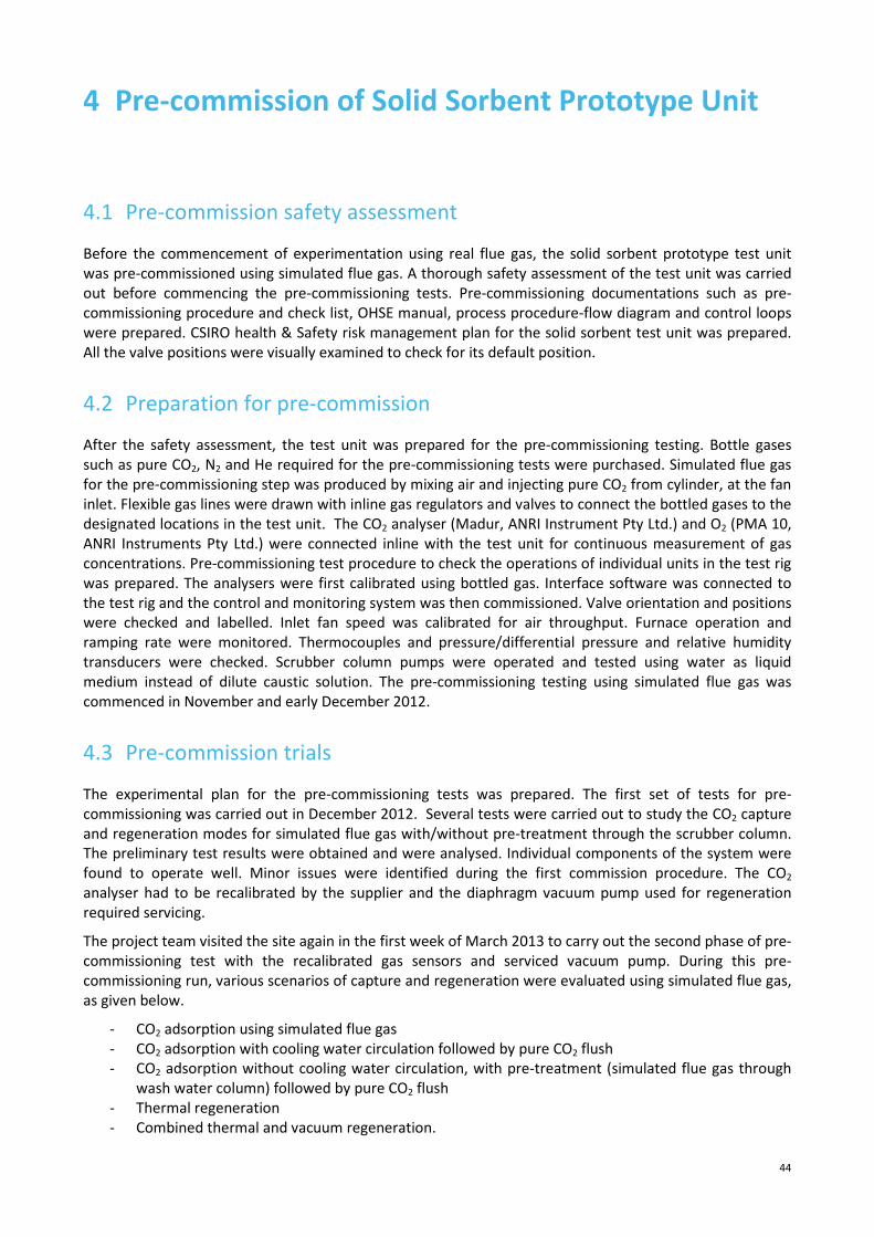
44
4 Pre-commission of Solid Sorbent Prototype Unit
4.1 Pre-commission safety assessment
Before the commencement of experimentation using real flue gas, the solid sorbent prototype test unit
was pre-commissioned using simulated flue gas. A thorough safety assessment of the test unit was carried
out before commencing the pre-commissioning tests. Pre-commissioning documentations such as pre-
commissioning procedure and check list, OHSE manual, process procedure-flow diagram and control loops
were prepared. CSIRO health & Safety risk management plan for the solid sorbent test unit was prepared.
All the valve positions were visually examined to check for its default position.
4.2 Preparation for pre-commission
After the safety assessment, the test unit was prepared for the pre-commissioning testing. Bottle gases
such as pure CO2, N2 and He required for the pre-commissioning tests were purchased. Simulated flue gas
for the pre-commissioning step was produced by mixing air and injecting pure CO2 from cylinder, at the fan
inlet. Flexible gas lines were drawn with inline gas regulators and valves to connect the bottled gases to the
designated locations in the test unit. The CO2 analyser (Madur, ANRI Instrument Pty Ltd.) and O2 (PMA 10,
ANRI Instruments Pty Ltd.) were connected inline with the test unit for continuous measurement of gas
concentrations. Pre-commissioning test procedure to check the operations of individual units in the test rig
was prepared. The analysers were first calibrated using bottled gas. Interface software was connected to
the test rig and the control and monitoring system was then commissioned. Valve orientation and positions
were checked and labelled. Inlet fan speed was calibrated for air throughput. Furnace operation and
ramping rate were monitored. Thermocouples and pressure/differential pressure and relative humidity
transducers were checked. Scrubber column pumps were operated and tested using water as liquid
medium instead of dilute caustic solution. The pre-commissioning testing using simulated flue gas was
commenced in November and early December 2012.
4.3 Pre-commission trials
The experimental plan for the pre-commissioning tests was prepared. The first set of tests for pre-
commissioning was carried out in December 2012. Several tests were carried out to study the CO2 capture
and regeneration modes for simulated flue gas with/without pre-treatment through the scrubber column.
The preliminary test results were obtained and were analysed. Individual components of the system were
found to operate well. Minor issues were identified during the first commission procedure. The CO2
analyser had to be recalibrated by the supplier and the diaphragm vacuum pump used for regeneration
required servicing.
The project team visited the site again in the first week of March 2013 to carry out the second phase of pre-
commissioning test with the recalibrated gas sensors and serviced vacuum pump. During this pre-
commissioning run, various scenarios of capture and regeneration were evaluated using simulated flue gas,
as given below.
- CO2 adsorption using simulated flue gas
- CO2 adsorption with cooling water circulation followed by pure CO2 flush
- CO2 adsorption without cooling water circulation, with pre-treatment (simulated flue gas through
wash water column) followed by pure CO2 flush
- Thermal regeneration
- Combined thermal and vacuum regeneration.

45
Simulated flue gas with CO2 concentration of about 13% was used for this study. Initially the feed gas was
bypassed through the column and then the gas was switched into the adsorbent column. It can be seen
from the Figure 24 that the CO2 concentration coming out of the column was almost zero, indicating that
almost all the CO2 in the flue gas has been adsorbed by the adsorbent. During this time no cooling water
was circulated through the column and due to the heat of adsorption (especially from CO2 adsorption),
there is about 10°C increase in column temperature. The adsorption run was stopped as soon as a slight
increase in CO2 concentration was noticed in the outlet (breakthrough point). The column was then flushed
with pure CO2 to replace other gases (like N2 and O2) that had co-adsorbed, and enrich the column with
CO2. Figure 25 shows the CO2 adsorption performance tested while cooling water was circulated through
the column during the capture process. CO2 capture with cold water circulation (near isothermal condition
of adsorbents) increases the adsorption capacity of adsorbents compared to operation without water
circulation. The CO2 adsorption efficiency was found to be over 98% during flue gas adsorption and CO2
flush.
Figure 24: CO2 capture performance of solid sorbent prototype unit using simulated flue gas
Another scenario tested was CO2 adsorption using simulated flue gas passed through the scrubber wash
column. For the pre-commissioning tests, water was used as the circulating liquid instead of dilute caustic
solution. For the pre-commissioning test, after passing through the wash column the simulated flue gas
with relative humidity of 86%, enters the solid adsorbent column. It can be seen from the Figure 25, the
CSIRO carbon fibre composite solid adsorbents were able to effective capture the CO2 even with the flue
gas containing moisture. The CO2 adsorption efficiency was over 98% during adsorption and during CO2
flush.
0
2
4
6
8
10
12
14
16
00:00 05:28 10:57 16:25 21:53 27:22
CO
2C
on
c., %
Time, min:sec
Flu
e g
as
sw
itch
into
co
lum
n

46
Figure 25: CO2 capture performance of solid sorbent prototype unit using simulated flue gas during cooling water
circulation followed by pure CO2 flushing
After CO2 flush, the adsorbents were heated to raise the adsorbent temperature (using air heated in the
furnace) to about 120°C to release the captured CO2 (desorption). The inlet and outlet of the column
remained closed during this heating stage. Once the adsorbent temperature reached the required
temperature, the outlet of the column was opened and vacuum was applied to extract the desorbed CO2
from the column. The desorbed CO2 concentration was found to be almost 100% throughout. It can be seen
from Figure 26, the combined thermal and vacuum regeneration was very effective method of desorption
to achieve very high CO2 concentration of up to 100 %. These results are in-line with the data obtained
from the studies using large scale unit under laboratory conditions.
The pre-commissioning tests using simulated flue gas was completed in Q1 2013. It was demonstrated
through these pre-commissioning tests that the CO2 capture solid sorbent prototype unit was fully
functional at the site and ready for trials with actual flue gas.
0
2
4
6
8
10
12
14C
O2
Co
nc.
, %
Time, min:sec
Inlet CO2 Conc - Bypass
Column
Outlet CO2 Conc- Fluegas
Through Column
Outlet CO2 Conc - Pure CO2
Flushing
CO2
CO2
CO2 CO2

47
Figure 26: Performance of solid sorbent prototype unit during adsorption, CO2 flush and combined thermal and
vacuum regeneration steps
0
10
20
30
40
50
60
70
80
90
100C
O2
Co
nc.
, %
Time, hr:min:sec
Flue gas Adsorption
Pure CO2 Flush
Adsorbent Heating
Combined Thermal &
Vac Regen
CO2

48
5 Site Trials and Demonstration with Real Flue Gas
5.1 Safety assessment before access to real flue gas
Extensive pre-preparation was required before the access to real flue gas to the solid sorbent prototype
unit. Documents for operational procedure with real flue gas, health & safety risk reviews, waste
management procedures were prepared according to Delta’s requirements. Measures to be adopted in
case of any emergency situations such as, when there is a flue gas leak, when there is a power failure, when
there is a leak in the caustic solution etc., were assessed in the risk review document. MSDS and chemical
and gas inventory registers were prepared and made available at work area on site for the solid sorbent
unit. Isolation procedure of the ammonia pilot unit was evaluated to safely operate the solid sorbent unit
with real flue gas, while personnel can continue working on the construction of the ammonia pilot unit. To
ensure safety, two additional manual valves (Figure 27) on the pilot plant unit pipelines were also installed.
SOx and NOx detectors in ambient air were installed on the solid sorbent test rig (Figure 28) to detect any
flue gas leaks from the test unit and were integrated into the control and monitoring system of the test
facility.
Figure 27: Photo of the additional manual valves on the feed and return flue gas lines in between two CSIRO’s CO2
capture units at the Power Station
Figure 28: Photo of the four channel hazardous gas detector installed on the solid sorbent test facility
After satisfactorily addressing CSIRO and Delta’s requirements in relation to the pre-preparations for the
supply of real flue gas to the solid sorbent prototype unit, flue gas to the solid sorbent test unit was
Flue gas
Flue gas

49
provided on the 29th May 2013. Figure 29 shows the photo of Delta personnel releasing the flue gas from
the stack to the solid sorbent test unit for the first time.
Figure 29: Opening of inlet flue gas pipeline on-site to provide flue gas to the solid sorbent test unit
5.2 Commission procedure and experimental plan
5.2.1 Commission procedure
Commissioning of the solid sorbent prototype unit with real flue gas followed by site trial demonstration
was commenced in June 2013. A step-by-step (comprising of 21 steps) commissioning procedure with real
flue gas was prepared. A check list of commissioning activities was prepared. Start up and shut down
procedures were prepared. After ensuring the operations of valve, temperature and pressure operations,
the chiller water circulation was checked. The furnace heating and ramping procedure was then evaluated.
The blower operation was then tested using the variable speed controller. The caustic scrubber unit using
circulation pumps was then tested. The adsorption column was heated using hot air/ hot flue gas and
cooled using chilled water. Vacuum pump operation was checked. The system was then shut down
adopting the shutdown procedure. Commissioning of the prototype test unit system was successfully
completed and ready for the site trials and demonstration using real flue gas in June 2013.
5.2.2 Methodology
For the carbon fibre composite adsorbents for CO2 capture site trial studies, an experimental plan was
developed with the consideration of project objectives. The first set of experiments were planned to
conduct CO2 adsorption and desorption tests using pre-treated flue gas. The pre-treatment of flue gas
involved particulate removal through the dust filter and passing through the caustic scrubber system to
mainly remove SO2 from the flue gas.
The second set of planned experimental study tested the performance of the carbon composite adsorbents
using the flue gas without the caustic scrubber pre-treatment system. However, the flue gas was still

50
passed through the dust filter. The experimental plan on the site trials and demonstration with two
scenarios is shown in Table 8.
Table 8: Experimental plan for CO2 capture site trials with two different scenarios
Experimental Plan
Scenario 1
Adsorption performance studies using real flue gas after pre-treatment with
particulate removal and caustic scrubber to remove SO2.
Adsorption, and then product purge
Thermal and vacuum swing regeneration with raw flue gas/hot air as heat source
Data processing and analysis
Scenario 2
Introduction of flue gas with SOx and NOx and evaluation of performance of solid
sorbents
Adsorption, and then product purge
Thermal and vacuum swing regeneration with raw flue gas/hot air as heat source
Data processing and analysis
Experiments were initiated systematically according to the experimental plan since June 2013. The overall
capture and regeneration strategy or the testing sequence involved in the solid sorbents testing is given as
a flow diagram in Figure 30.
Figure 30: Process sequence procedure for the solid sorbent CO2 capture and regeneration testing
The raw flue gas from the stack was extracted by the blower and passed through a HEPA cartridge filter
(99.9 % efficient at 0.3micron) (Solberg International Pty Ltd) and either passed through the caustic
scrubber for SOx and some NOx removal, or bypassed the scrubber column to provide flue gas for the CO2
capture by solid sorbents. After the CO2 adsorption step, pure CO2 was passed into the adsorption column,
which helps in enriching the adsorbed CO2 by removing the N2 (and O2) co-adsorbed from the flue gas. The
adsorbents were then heated to 110°C with inlet and outlet of the adsorption column closed during
heating. The heat releases the CO2 adsorbed by the sorbent material and once the desired temperature
was reached, the adsorption column was opened to recover the adsorbed CO2. Vacuum was also applied
simultaneously to extract the CO2 from the material. The CO2 adsorption efficiencies were studied by
analysing the raw flue gas composition and at the outlet of the adsorption column. The concentration of
CO2 during regeneration was also continuously monitored. The total amount of CO2 recovered was
evaluated by comparing the amount of CO2 captured (or passed into the adsorption column) and amount
Flue gas IN
Caustic Scrubber
System for Flue gas
Pre-treatment
Adsorption/ Gas
captureCO2 Flushing
Thermal & Vacuum
Swing Regeneration
CO2 Recovered
from Fluegas
Recovered CO2 for FlushingFlue gas without Pre-treatment

51
desorbed (extracted out of the column). Gas concentration in the flue gas was measured using the gas
sensors. In order to effectively evaluate the CO2 capture performance and adsorbent stability, we define
the following performance parameters.
CO2 adsorption efficiency
���� =�
�× 100% (1)
Where, a is amount of CO2 in the flue gas entering into the adsorption column during the
adsorption stage; c is amount of CO2 adsorbed by the adsorbent during the adsorption stage; ƞCap is
the CO2 adsorption efficiency that is determined based on the adsorption breakthrough profile.
CO2 desorption efficiency
���� =
���× 100% (2)
Where, a is amount of CO2 entering into the adsorption column during the adsorption stage; b is
amount of the product CO2 used for the purge (CO2 flushing); d is amount of CO2 collected during
the desorption stage; ƞRec is the CO2 desorption efficiency that is determined based on total CO2
desorbed from the adsorbent.
5.2.3 Analytic instruments
The solid sorbent test unit used CO2 sensor (Madur, Anri Instruments Pty Ltd), O2 sensor (PMI 10, Anri
Instruments Pty. Ltd.) and a combined sensor for analysis of SOx, NOx and CO (and CO2) (Thermo 60i, non
dispersive infrared technique). For initial tests very high peaks of gas concentrations, especially for CO,
were noticed from Thermo 60i instrument during the regeneration. The mixture of gas composition with
the combination of very low CO2 concentration (during capture) and very high CO2 concentration (during
regeneration) presented a unique background environment for the analysis equipments. Very high peaks of
some gas concentrations, especially for CO, were actually caused due to the analysers response to the
change in gas composition background environment. A single analyser to measure various gases present in
the flue gas was not an accurate method operation. Therefore, to address this issue, individual sensors to
measure SO2, NOx, CO, O2 and CO2 were required to accurately measure the gas concentrations in order to
get reliable and consistent data. Individual sensors for SO2 (Thermo 43i-HL, UV fluorescence), NOx (Thermo
42i-HL, Chemiluminescence), and CO (Thermo 48i) were obtained (Figure 31) in September 2013 and
together with the available O2 and CO2 analysers, formed a suite of analyses equipments used in this study.
Figure 31: Individual analysers for measuring SO2, NOx and CO used for the solid sorbent CO2 capture site trial

52
5.3 Results and discussions
5.3.1 Pre-treatment performance
The first series of experimentation were carried out by passing the raw flue gas through the caustic
scrubber system (with pre-treatment) before CO2 capture. Figure 32 shows the concentration of gases in
the flue gas before and after caustic scrubber pre-treatment (operated at pH 9). It can be seen that the
caustic scrubber removed mainly SO2 (97.5%), some NO (7.9%) and NO2 (15.3%) and there was negligible
change in CO2 and CO concentrations. The percentage removal efficiencies of various gases were
determined from the difference in concentrations between the inlet and outlet of the scrubber column,
expressed as percentage. The caustic solution required periodic replacement or replenishment in order to
maintain the performance of the scrubber.
Figure 32: Concentration profile of flue gas at the inlet and outlet of caustic scrubber column
5.3.2 CO2 capture performance with pre-treatment (Scenario 1)
After the commissioning of test facility with actual flue gas, experiments were carried out with the flue gas
pre-treatment. As an example, overall CO2 concentration profile for one test during the process of CO2
capture and regeneration with flue gas pre-treatment through scrubber is shown in Figure 33. Extracted
raw flue gas with CO2 concentration of 10-13% was passed through the scrubber column (with caustic
solution pH 9). There was very little change in CO2 concentration at the outlet of scrubber and the flue gas
was sent into the adsorption column containing the carbon fibre composite solid sorbents, for CO2 capture.
The CO2 concentration at the outlet of adsorption column contains very negligible amount of CO2 (0.01%)
as over 98% of CO2 gets adsorbed by the sorbents. When the concentration at the outlet began to increase
(known as the point of breakthrough), the adsorption process was stopped and pure CO2 was passed into
the column. The CO2 concentration at the outlet of the column remained to be very low (<0.5%) as pure
CO2 was further adsorbed by displacing other gases like nitrogen adsorbed from the flue gas during the
capture step. The CO2 flushing was stopped once the outlet CO2 concentration starts to increase. The
adsorption column was closed and adsorbents were heated by passing hot air through the regeneration
tubes (13x12.7mm tubes through the sorbents). Once the adsorbent temperature reached 110°C, the
column was opened to extract the gas that has desorbed (regeneration step). Vacuum was also applied to
bring out the desorbed gases. The outlet concentration of CO2 was found to be over 97%. The desorption
efficiency as shown in equation (2) for CO2, was found to be between 90-95%. Figure 34 shows the
concentration profiles of SO2 and NOx for the solid sorbent capture system. It can be seen that the CO2 as
CO2 v% 10.9
SO2 ppmv 3.3
NO ppmv 290
NO2 ppmv 15.24
CO ppmv 6.04
Raw Flue gas at Scrubber Outlet
CO2 v% 11.5
SO2 ppmv 132.6
NO ppmv 315
NO2 ppmv 18
CO ppmv 6.8
Raw Flue gas at Scrubber Inlet

53
well as the remaining SO2 and NOx in the flue gas stream were adsorbed by the solid sorbents. The
response of the NOx sensor was slower compared to CO2 and SO2 sensors and so the drop in NOx
concentration at the point of switching the flue gas into the adsorption column is shifted (Figure 34). During
thermal regeneration, concentration of NO was noticed in the desorbed gas, but no SO2. SO2 is possibly
being retained in the adsorbents, or being transformed.
Figure 33: CO2 concentration profile during capture and regeneration process with flue gas pre-treatment
0
10
20
30
40
50
60
70
80
90
100
0:00:00 0:14:24 0:28:48 0:43:12 0:57:36
CO
2C
on
c.,
%
Time, h:m:s
Flu
e G
as
Du
rin
g P
re-t
rea
tme
nt
Flu
e G
as
Ou
t D
uri
ng
Ca
ptu
re &
Pu
rge
Re
ge
ne
rati
on
Ste
p
Ra
w F
lue
Ga
s

54
Figure 34: Gas concentration profiles for solid sorbent CO2 capture and regeneration process with flue gas pre-
treatment
5.3.3 CO2 capture performance without pre-treatment (Scenario 2)
5.3.3.1 CO2 capture performance
One of the key objectives of the project was to determine the stability of carbon fibre composite
adsorbents under actual flue gas conditions. Hence, after the completion of four CO2 capture tests with the
flue gas pre-treatment, we have conducted over 200 tests on the CO2 capture performance without the
pre-treatment of flue gas except the dust filtration by the barrier filter. Figure 35 shows the performance of
the solid sorbent for CO2 capture without flue gas pre-treatment. The CO2 adsorption efficiency was found
to be over 98% even without flue gas pre-treatment and in the presence of SO2 and NOx, which were also
completely co-adsorbed from the raw flue gas. Regeneration of the sorbents yielded high purity of CO2
(over 97%). The CO2 desorption efficiency was between 90-95% even without the caustic pre-treatment of
the flue gas. Even after 200 experiments, the CO2 adsorption performance of the solid sorbents was able to
be maintained without any noticeable influence on the CO2 capture performance due to the presence of
SO2 and NOx in the flue gas.
0
50
100
150
200
250
300
350
0
10
20
30
40
50
60
70
80
90
100
07:12 15:33 23:54 32:15 40:36 48:58
Ga
s C
on
cen
tra
tio
n, p
pm
CO
2C
on
cen
tra
tio
n, %
Time, m:s
CO2 SO2 (ppm)NO (ppm) NO2 (ppm)CO2 vol% SO2 ppmv
NO ppmv NO2 ppmv

55
Figure 35: Gas concentration profiles for solid sorbent CO2 capture and regeneration process with flue gas pre-
treatment
5.3.3.2 Repair of column for desorbed gas leakage
After 35 runs, a gas leak from the column was noticed at the top and bottom part of the column during the
regeneration as shown in Figure 36. It was identified that this was due to the damage of o-rings in October
2013. Then the leaking was fixed by applying high temperature metal oxide epoxy sealing patty as shown in
Figure 37 in November 2013, and then the site trials recommenced.
Figure 36: Photo showing the gas leaking from the adsorption column
About 110 runs were carried out between Nov 2013-Feb 2014 and the project team noticed a recurrence of
the leaking problem. Although the sealant applied was able to withstand the applied heat, the repeated
0
50
100
150
200
250
300
350
0
10
20
30
40
50
60
70
80
90
100
110
00:00 03:57 07:53 11:50 15:47 19:44 23:40
Ga
s C
on
cetr
ati
on
, pp
m
CO
2C
on
cen
tra
tio
n, %
Time, m:s
CO2 vol% SO2 ppmv
NO ppmv NO2 ppmvSO2
NO2NO
CO2

56
heating and cooling made the material to deform (Figure 38). As a result, gas leakage was again noticed at
the top and bottom of the adsorbent column. Close observation of the results showed no reduction in the
CO2 adsorption efficiency of the solid sorbents, indicating that the sorbent material performance to adsorb
CO2, was being maintained. During the normal test operation, the adsorbents after CO2 capture from flue
gas were heated to 100°C to desorb the gases from the adsorbent material. During this regeneration step,
the inlet and outlet of the adsorption column were sealed to hold the desorbed gas within the column until
a certain time till the gases have been desorbed (determined by the pressure transducer monitoring the
pressure build up inside the column). Due to the leaking of the desorbed gas from the column, during the
regeneration step, the column pressure dropped as it escaped from the column before the column was
opened to recover the gas. Due to inadequate sealing of the adsorption column, the CO2 desorption
efficiency (the difference between the CO2 captured by the adsorbents and the amount of CO2 extracted
out during regeneration), expressed as percentage, dropped to an average of 75% from originally obtained
90-95% at the start of the site trial.
The project team was committed to fix the column leak and demonstrate the performance of the solid
sorbent. It was important to carry out the remaining planned tests without gas leak and to ensure that the
stability of the solid sorbent was determined correctly. Further attempts to seal the column with more
thermal cycle resistant stainless steel based sealants (EK456), which were also not effective as the leaks
could not be contained. Clearly, a ‘quick-fix’ failed to work. Considering the importance to maintain the
project milestone timeline, the corrective measure adopted this time, to fix the gas leak from the column
was to redesign the regeneration section on the top and bottom of the column. It was decided to remove
the existing sealant and weld the thirteen hot air circulation tubes with the flanges, at the points where it
exits the top and bottom of the column. Also, the water and hot air distribution manifold was eliminated
with a more simple design. Figure 39 shows the sketch of the redesigned regeneration section with a steel
cap consisting of ports for flue gas, hot air and cold water circulation through the column.
Figure 37: Photo of column resealing with high temperature epoxy sealant
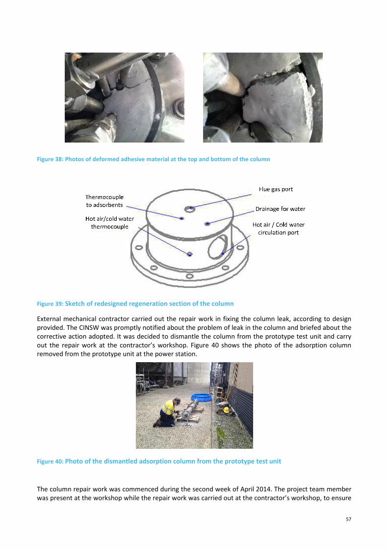
57
Figure 38: Photos of deformed adhesive material at the top and bottom of the column
Figure 39: Sketch of redesigned regeneration section of the column
External mechanical contractor carried out the repair work in fixing the column leak, according to design
provided. The CINSW was promptly notified about the problem of leak in the column and briefed about the
corrective action adopted. It was decided to dismantle the column from the prototype test unit and carry
out the repair work at the contractor’s workshop. Figure 40 shows the photo of the adsorption column
removed from the prototype unit at the power station.
Figure 40: Photo of the dismantled adsorption column from the prototype test unit
The column repair work was commenced during the second week of April 2014. The project team member
was present at the workshop while the repair work was carried out at the contractor’s workshop, to ensure

58
the work was carefully performed without disturbing or causing any damage to the adsorbents inside the
column. Figure 41 shows the repair work on the column being carried out the workshop.
Figure 41: Photos of the repair work carried out on the adsorption column
After welding of tubes and sealing the leaks, the column was leak tested. The column was pressurised to
150 kpa and checked if it was able to hold the pressure for 10-15 mins. Then the top and bottom section of
the column was immersed in a water container and was checked for any air bubbles from the column.
Figure 42 shows the photos of column leak tests carried out at the contractor’s workshop.
Figure 42: Photos of column leak test performed at the workshop
Once the column was checked for leaks and ensured all the leaks have been completely sealed, the top and
bottom steel caps were fixed to the column. After completion of the column repair, it was transported to
the power station and installed to the prototype test unit. Figure 43 shows the picture of the redesigned
and newly constructed regeneration section of the column.

59
Figure 43: Photo of the redesigned regeneration set-up with welding of regeneration tubes at the top of the
adsorbent column
5.3.4 Adsorbent stability
Final column repair work was completed on 16th April 2014 and the site trial testing was commenced on
17th April 2014. The remaining number of experiments were carried out as planned. Figure 44 shows
performance of the solid sorbents with real flue gas during the course of the site trial where more than 200
adsorption and regeneration cycles were conducted to demonstrate the stability of the adsorbents to real
flue gas. The CO2 adsorption efficiency from real flue gas was consistently over 98% (Figure 44) for the solid
sorbents, throughout the site trial study period. Even during the column leak period, the CO2 adsorption
efficiency was not affected. The desorption efficiency for CO2 was found to be between 90-95% and it
dropped to an average of 75% during the leaking of desorbed gas. Due to the leaking of desorbed CO2 from
the column during regeneration, the desorption efficiency was found to be low. However, after the column
was sealed for the leak it was evident from Figure 44 that the CO2 desorption efficiency increased back to
90-95%, which was the performance at the start of the site testing. This demonstrated the fact that even
after 200 cycles the performance of solid sorbents was able to be maintained indicating the excellent
stability of the carbon fibre composite adsorbents towards real flue gas without the pre-cleaning of SOx and
NOx, particularly in terms of the CO2 adsorption efficiency. Table 9 summarises the site trials including tests
with the gas leaking issue. All the planned tasks set out in this project were successfully accomplished
through this study.
Table 9: Statistics of the site trial studies
Experimentation Number of Tests
Total Number of tests undertaken 207
Tests under Scenario 1 (with flue gas pre-treatment) 18
Tests under Scenario 2 (without flue gas pre-treatment) 189
Tests with the column leaking issue 79
Tests without the column leaking issue 128
Tests under set condition*
Tests under other condition
93
114
* Adsorption temperature 25°C, adsorption flow rate 45-55 L/min, CO2 purge amount 109-112L, total
amount of CO2 captured 137-141L, combined thermal and vacuum regeneration, desorption column
temperature 100-110°C, vacuum pressure 20-25 kPa

60
Figure 44: Performance and stability of carbon composite solid sorbents
For most of experimental results presented in Figure 44, the amount of the product CO2 used for the purge
was about four times of the amount of CO2 from the flue gas adsorbed by the adsorbent. Hence this
approach needs to be further evaluated as the increase in purge quantity decreases the CO2 recovery and
also results in energy loss associated with adsorption heat released and increases the desorption energy
required [118]. Nevertheless, if this technology is to be pursued for the CO2 capture with high purity gas
product, it is necessary to further investigate better regeneration processes. The effect of small quantities
of flue gas impurities like NO on the properties and behaviour of CO2 in compression and pipeline
transportation system is uncertain, and needs to be investigated. However, this is a similar issue faced by
oxy-fuel CO2 capture technology [119].
5.4 Key learning from the site trials
The solid sorbent CO2 capture site trial and prototype unit demonstration project commenced in Q1 2011
and the site trial was completed in May 2014. Along the study period many challenges were faced and key
lessons were learnt. Some of the key learnings from this study are discussed below.
• The original scope of the project was to operate the solid sorbent prototype unit along with
ammonia based pilot plant and to obtain pre-treated flue gas to the solid sorbent unit from a slip
stream from ammonia based process. It was soon evident that the original plan of extracting pre-
treated flue gas from the ammonia pilot plant was not achievable as the timelines of operation for
the ammonia pilot plant experienced delays and would not be matched with the project timelines
for solid sorbent site trials. This resulted in the development of entire pre-treatment system into
the solid sorbent prototype unit to be able to pre-treat the flue gas and operate independently. The
pre-treatment system was designed and built. Building an additional infrastructure of a self-
0
10
20
30
40
50
60
70
80
90
100
0
10
20
30
40
50
60
70
80
90
100
0 25 50 75 100 125 150 175 200
CO
2D
eso
rpti
on
Eff
icie
ncy
, %
CO
2A
dso
rpti
on
Eff
icie
ncy
, %
Run Number
Adsorption
Desorption

61
contained pre-treatment system to the solid sorbent prototype test unit, caused some delays in
meeting the project milestones on time and substantially increased the project expenditure.
• The project experienced some delays between the completion of infrastructure and installation of
prototype unit on-site. Due to the delays in the site access, the construction of concrete basement
on-site for pilot plant installation was experienced by ammonia pilot plant, which somehow
delayed the on-site installation of prototype unit. Substantial delay in accesses to the real flue gas
to the solid sorbent unit was also encountered, and this is because it took unexpected long time to
set up major flue gas pipelines connected to the stack, and then to get it ready to supply the real
flue gas with a number of safety concerns sorted out. Also, additional safety sensors to detect SOx,
NOx in air during an event of flue gas leak were also required to be installed on the solid sorbent
test unit. In general, some site research activities and tasks are not easily managed, and a lot of
time was spent than earlier planned.
• It was apparent that due to the unique gas compositions and concentrations encountered during
CO2 capture process from actual flue gas, a single analyser to measure various gases was not an
accurate method of operation in order to evaluate the performance. An analytical suite with
individual sensors for CO2, O2, SO2, NOx and CO were required to precisely measure the gases
during testing process.
• During the capture and regeneration operation, the repeated heating and cooling of adsorbent
column resulted in the heat related stresses to the joints and o-rings. This led to the wearing of o-
rings, sealing the top and bottom of the adsorbent column. This resulted in the leakage of desorbed
gases from the column thus affecting the overall recovery of CO2 during the operation. Application
of high temperature sealant to fix the leaks was not successful as the sealants were deformed due
to heating and cooling cycle. Welding the regeneration tubes permanently sealed the leaks. Better
design of the adsorption column and the regeneration tubes in the first place could have avoided
the leaking problem.
• Adsorbent regeneration using hot air through 13 ss tubes was found to be not very effective in
heating the adsorbent material as it required significant time (20-30mins) to heat the adsorbent
materials (from 30-110°C) and resulted in significant idle time during the operation. However, time
for adsorbent cooling using chilled water was substantially shorter. So, it is very important to
develop a rapid heating process.

62
6 Preliminary Process Configuration and Life Cycle Assessment
6.1 Preliminary process configuration and energy consumption analysis
6.1.1 Process configuration
A column with a diameter of 7 m and a height of 2 m was selected in the process configuration. Deploying a
same column height in the current design as in the large scale test was aimed to adopt the experimental
results of pressure drop obtained earlier. The diameter of column chosen is double the column size
reported for the process design of packed beds using particulate carbonaceous adsorbents [66].
The following five-stage process includes: the flue gas flows through the adsorbent column for CO2
adsorption (designated as capture stage); once the breakthrough is reached, the flow of flue gas will be
switched to the 2nd column for continuous capture while the 1st column will be purged by flowing product
CO2 which is recycled from captured CO2 (designated as purge stage). When purge is completed, the 1st
column will be heated to 105 oC for thermal regeneration (designated as thermal swing stage) followed by
extracting residual adsorbed CO2 using vacuum (designated as vacuum swing stage), and finally cooled
down to 30 oC (designated as cooling stage) ready for next cycle of capture. The above process sequence
configuration agrees with the process trialled in the current project. Table 10 shows the sequential
description of the solid adsorbent CO2 capture process involving two columns and five-stage operations.
The total duration for four stages of purge, thermal swing, vacuum swing and cooling equals to the time
required for the capture stage. A complete cycle requires 20 minutes.
Table 10: Sequential description of one cycle of CO2 capture process involving two columns and five-stage
operations
Due to the low heat capacity of solid adsorbents and the low heat of CO2 adsorption in our process based
on CO2 physisorption, adsorbents could be regenerated at a relatively low temperature and therefore it is
potentially valid for utilising the waste heat from hot flue gas streams for thermal regeneration. It is
designed to exchange the flue gas heat to liquid fluids which exchange heat with adsorbents and columns.
In this way it is possible to achieve rapid heating as the heat transfer coefficient of liquid is significantly
higher than gases. While the pressured water at 120 oC was used in the current process configuration,
optimised fluids with a higher boiling point and improved heat transfer properties would be used in the
future design.
6.1.2 Process simulation and energy consumption estimation
The HYSYS process simulation was carried out on the current process configuration to estimate the energy
consumption based on the process parameters given in Table 11.
Time, min 1 2 3 4 5 6 7 8 9 10 11 12 13 14 15 16 17 18 19 20
Column I
Column II CaptureCO2 purge Heating-thermal swing Vacuum swing Cooling
Capture CO2 purge Vacuum swingHeating-thermal swing Cooling
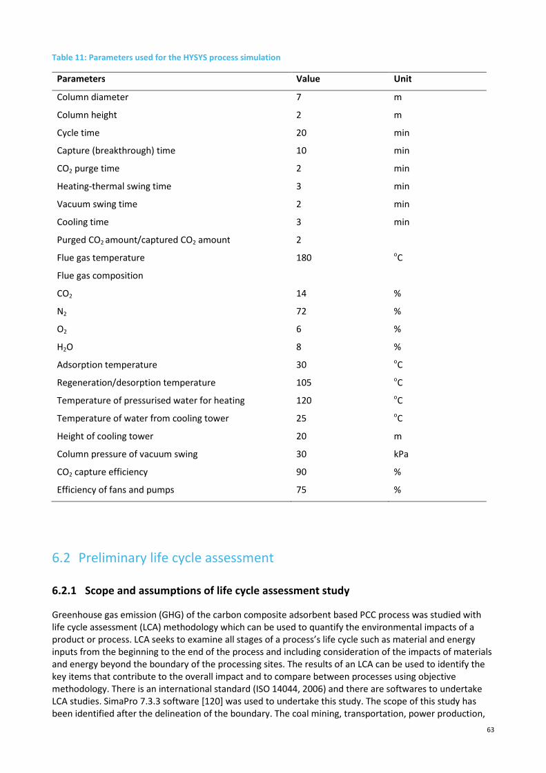
63
Table 11: Parameters used for the HYSYS process simulation
Parameters Value Unit
Column diameter 7 m
Column height 2 m
Cycle time 20 min
Capture (breakthrough) time 10 min
CO2 purge time 2 min
Heating-thermal swing time 3 min
Vacuum swing time 2 min
Cooling time 3 min
Purged CO2 amount/captured CO2 amount 2
Flue gas temperature 180 oC
Flue gas composition
CO2 14 %
N2 72 %
O2 6 %
H2O 8 %
Adsorption temperature 30 oC
Regeneration/desorption temperature 105 oC
Temperature of pressurised water for heating 120 oC
Temperature of water from cooling tower 25 oC
Height of cooling tower 20 m
Column pressure of vacuum swing 30 kPa
CO2 capture efficiency 90 %
Efficiency of fans and pumps 75 %
6.2 Preliminary life cycle assessment
6.2.1 Scope and assumptions of life cycle assessment study
Greenhouse gas emission (GHG) of the carbon composite adsorbent based PCC process was studied with
life cycle assessment (LCA) methodology which can be used to quantify the environmental impacts of a
product or process. LCA seeks to examine all stages of a process’s life cycle such as material and energy
inputs from the beginning to the end of the process and including consideration of the impacts of materials
and energy beyond the boundary of the processing sites. The results of an LCA can be used to identify the
key items that contribute to the overall impact and to compare between processes using objective
methodology. There is an international standard (ISO 14044, 2006) and there are softwares to undertake
LCA studies. SimaPro 7.3.3 software [120] was used to undertake this study. The scope of this study has
been identified after the delineation of the boundary. The coal mining, transportation, power production,

64
post combustion capture and compression of processed output CO2 gas ready liquefaction has been
included.
The following main assumptions have been made to undertake this study.
- Reference power-station CO2 emission factor: 1040 kg CO2/MWh (SimaPro software for NSW
electricity)
- Compression pressure of CO2 increased before liquefaction: to 90 bar
- Energy of black coal: 27 GJ/t
- Average transport distance by rail from coal mine to power plant: 100 km
- Water use in coal mine: 0.27 t water/t coal (source Australasian unit process within SimaPro)
- Auxiliary heat required for regeneration of carbon adsorbents comes from the steam cycle of the
power plant
There are other appropriate and reasonable assumptions made to carry out this LCA study.
Two scenarios were considered in the LCA of the carbon adsorbent based PCC process for the 350 MW unit.
In the first scenario (referred to as partial flue gas treatment), the adsorbent PCC process was applied to
treat a fraction of the flue gas generated from the 350 MW unit (63 m3/s) and no additional heat would be
required for adsorbent regeneration. The second scenario (complete flue gas treatment) considered
treating the complete stream of the flue gas generated from the 350 MW (472 m3/s), 63 m3/s of which was
treated by the process with the flue gas waste heat as described in Scenario 1 while the remaining 409 m3/s
flue gas was processed by additional heat taken from the steam plant of the power plant.
Life cycle inventory (LCI) data tables have been developed based on HYSYS flowsheet data, mass and
energy balances. The LCI data for coal mining and coal transport were taken from a LCA study of the PCC
process based on monoethanolamine (MEA) [121]. The LCI estimate for coal mining was based on power
station capacity (669.8 MW), efficiency (35.6%) and coal energy value (27 MJ/kg), while 100 km was
assumed distance by rail for coal transport. For comparison purpose, the same LCI data for coal mining and
coal transport were used in the LCA of all evaluated PCC processes. The contribution of carbon adsorbent
material and manufacturing has been estimated based on 20 years life design of the PCC plant.
The captured CO2 product needs to be compressed for transportation and storage. A final pressure of 110
Bar was adopted here. The total electricity requirement for CO2 compression from 1.5 to 110 Bar was
estimated at 94 kWh/t CO2 captured [122], and about 88-98 kWh/t CO2 captured was reported for CO2
compression to 110 Bar depending on the compression configuration [123]. In this study, we took 100
kWh/t CO2 captured as the CO2 compression electricity consumption.
6.2.2 Greenhouse gas emissions
Carbon emission from power plants is a major contribution towards the increase of CO2 concentration in
the atmosphere globally. The GHG emissions have been estimated for both scenarios of carbon composite
adsorbent process considering adsorbent materials and energy use for each scenario. The following four
parts of CO2 footprints have been taken into account in the estimation of GHG emissions for carbon
adsorbent based PCC process.
1. GHG footprints are from coal mining and coal transport, which were kept the same for different
capture processes.
2. The amount of CO2 that is not captured in PCC plant is accounted as an emission stream to the
atmosphere based on the CO2 capture efficiency of the PCC process.
3. CO2 footprint is due to materials and fabrication of carbon composite adsorbents.
4. CO2 footprint is due to energy consumption by the PCC process including all electrical power
required by PCC equipments and extra auxiliary heat taken from the steam plant of the power
65
plant. All these above will draw electrical power from the power plant as shown in LCI data tables.
The electricity that is used for the PCC plant will not be delivered from this power plant to the grid
and may need to be supplied from the NSW State Electricity grid. This electricity from the grid will
have CO2 emission associated and is accounted here as the CO2 footprint penalty for replacing lost
power from the grid due to PCC-induced efficiency loss at the power plant. The carbon emission
from the NSW grid based on coal-fired power generation is found to be 1,040 kg CO2/MWh
[120,124]. It has to be mentioned that the CO2 intensity of the electricity used for the capture plant
will have a sizeable impact on the CO2-footprint of the capture process. For example, if the
electricity is taken from a renewable power generation source, the CO2 footprint penalty will be
significantly reduced, such as the carbon emission of 16.5 kg CO2/MWh for electricity from wind
[125].
LCA studies can include other impacts such as acidification, abiotic depletion, ozone layer depletion,
toxicity, land use etc. These numbers can be generated and reported if needed. For this study, CO2 emission
has the main focus since this is the most significant impact from a power plant. If next impact is to be
prioritised, acidification and water resource depletion can be selected in further extension of this study.
The results can be normalised for Australian population by estimating per capita impact. There is a debate
among the LCA practitioners about use of weighting factors for each indicator which may introduce
subjectivity with the results. This study has not used any weighting factors.
The GHG emission results per tonne of CO2 captured for both scenarios of carbon composite adsorbent
based PCC process were determined. For comparison, the GHG footprint results of the MEA process which
was assessed in a similar LCA methodology [121] were used.
For Scenario 1 of carbon adsorbent process, the total GHG emission will be 295.6 kg CO2-e per tonne of CO2
captured if the electricity used for the PCC plant is replaced by coal-fired power generation. The total GHG
emission for Scenario 2 is 497.3 kg CO2-e per tonne of CO2 captured based on electricity taken from coal-
fired power generation. The total GHG emission of Scenario 2 is over 68.2% higher than that of Scenario 1
but about 5.5% lower than that of the MEA process (526.0 kg CO2-e/t CO2 captured).

66
7 Conclusions and Recommendations
7.1 Conclusions
The site trials and demonstration of the carbon fibre composite solid sorbent CO2 capture prototype unit
was successfully carried out at Delta Electricity power station. The solid sorbent prototype unit was
successfully designed, constructed, commissioned and tested using real flue gas. Over 200 adsorption and
regeneration tests were performed on-site using real flue gas. Various operating parameters were varied
during the course of testing to evaluate the performance of the adsorbents, and key performance data and
operational experience were obtained. Major technical findings are concluded below.
CO2 adsorption efficiency, adsorbent stability and product purity
The CO2 adsorption efficiency for the solid sorbents using real flue gas from coal fired power station
was found to be consistently over 98%. The desorption efficiency in terms of CO2 was found to be
between 90-95% and the solid adsorbents were demonstrated to be very stable towards real flue gas
without any removal of SOx and NOx as the performance of the material was maintained even after
more than 200 tests.
Adsorption and then by pure CO2 flushing enabled the captured product recovered by combined
thermal and vacuum regeneration with a high purity of about 99% CO2. However, this approach needs
to be further evaluated as it results in energy loss associated with adsorption heat released and
desorption energy required. It would be much better to devise an alternative regeneration process
without the need of CO2 flushing to achieve the better capture efficiency.
Process configuration and LCA
A five-stage CO2 capture-regeneration process configuration was designed for the honeycomb
monolithic carbon composite adsorbent based PCC process. Two scenarios of carbon adsorbent process
were investigated in the LCA: Scenario 1 assumed the carbon adsorbent process treated a fraction of
flue gas generated only relying on the flue gas waste heat for regeneration, while Scenario 2 considered
treating the complete flue gas stream generated with extra auxiliary heat from steam extracted from
the power plant.
Preliminary LCA results showed that the GHG emission for carbon adsorbent Scenario 1 is lowest at
295.6 kg CO2-e/t CO2 captured if the electricity used for the PCC plant replaced by coal-fired power
generation. Scenario 2 has a GHG footprint of 497.3 kg CO2-e/t CO2 captured which is over 68.2% higher
than Scenario 1 but about 5.5% lower than the MEA process at 526.0 kg CO2-e/t CO2 captured.
7.2 Recommendations
For the carbon adsorbents for the post combustion CO2 capture, so far studies have been carried out only
using simulated flue gas and under laboratory conditions. Hence, through this CINSW project the site trials
and demonstration of the carbon composite adsorbents for CO2 at the power station is a pioneering
research in the world to study the capture performance and captured gas quality using real flue gas. The
important experimental data and site operational experience obtained at the power station form a basis for
further development of this carbon composite adsorbent CO2 capture technology towards its application at
fossil fuel fired power stations. Before the development and demonstration of a carbon adsorbent pilot
scale plant for CO2 capture, it is recommended further research needs to be conducted to obtain critical
operational parameters and experience for the design of the pilot scale plant.

67
References
[1] Australian Government. Emissions reduction fund white paper. April 2014.
[2] http://www.environment.nsw.gov.au/climatechange/emissionsoverview. Accessed on 12
May 2014.
[3] Thiruvenkatachari, R., Su, S., An, H., Yu, X.X., 2009. Post combustion CO2 capture by carbon
fibre monolithic adsorbents. Progress in Energy and Combustion Science 35, 438-455.
[4] IEA. CO2 capture at power stations and other major point sources. Zero emission
technologies for fossil fuels. OECD/IEA, Cedex, France; 2003.
[5] Canadell J.G., Pataki D.E., Pitelka L.F., editors. Terrestrial Ecosystems in a Changing World.
Springer-Verlag Publishe; 2007.
[6] Josep G. Canadell, Corinne Le Que´re´, Michael R. Raupach, Christopher B. Field, Erik T.
Buitenhuis, Philippe Ciais, Thomas J. Conway, Nathan P. Gillett, R. A. Houghton, and Gregg
Marland. 2007. Contributions to accelerating atmospheric CO2 growth from economic
activity, carbon intensity, and efficiency of natural sinks. PNAS 2007; 104: 18866–18870.
www.pnas.org/cgi/doi/10.1073/pnas.0702737104.
[7] IEA. World Energy Outlook 2002. 2nd Edition. OECD/IEA; 2002.
[8] IEA. CO2 emissions from fossil fuel combustion 1971-2000. 2002 Edition. International
Energy Agency (IEA), Paris; 2002.
[9] Beecy D., Kuuskraa V., 2001. Status of U.S. geologic carbon sequestration research and
technology. Environ Geosci, 8(3), 152-159.
[10] IEA. Capturing CO2. IEA greenhouse gas R&D programme; 2004. ISBN : 978-1-898373-41-4
[11] Damen K., Troost M. van, Faaij A., Turkenburg W., 2006. A comparison of electricity and
hydrogen production systems with CO2 capture and storage. Part A: Review and selection
of promising conversion and capture technologies. Progress in Energy and Combustion
Science, 32(2), 215–246.
[12] Wall T.F. Combustion process for carbon capture. Proceedings of the Combustion Institute
2007; 31:31-47.
[13] IPCC. IPCC special report on carbon dioxide capture and storage. Cambridge University
Press, USA; 2005.
[14] Wallace D. Capture and storage of CO2. What need to be Done? In: Proceedings from COP 6
The Hauge; 2000, p 13-24.
[15] Buhre B.J.P., Elliott L.K., Sheng C.D.,Gupta R.P., Wall T.F. 2005. Oxy-fuel combustion
technology for coal-fired power generation. Prog Energy Combust Sci, 31, 283–307.
[16] Smith A.R., Klosek J., 2001. A review of air separation technologies and their integration
with energy conversion processes. Fuel Processing Technology, 70, 115–134.
[17] Vinson D.R., 2006. Air separation control technology. Computers and Chemical
Engineering, 30, 1436–1446.
[18] Engels S. and Modigell M., 2006. Development of a zero emission coal-fired power plant by
means of mixed ion conducting high temperature membranes. Desalination, 199, 291-292.
[19] Ito W., Nagai T., Sakon T., 2007. Oxygen separation from compressed air using a mixed
conducting perovskite-type oxide membrane. Solid State Ionics, 178, 809–816.
[20] Ren J.Y., Fan Y., Egolfopoulos F.N., Tsotsis T.T., 2003. Membrane-based reactive
separations for power generation applications: oxygen lancing. Chemical Engineering
Science, 58, 1043 – 1052.

68
[21] Dyer P.N., Richard R.E., Russek S.L., Taylor D.M. 2000. Ion transport membrane technology
for oxygen separation and syngas production. Solid State Ionics, 134, 21-33.
[22] Richter H.J. and Knoche K. Reversibility of combustion processes, efficiency and costing,
Second Law Analysis of Processes. ACS symposium, vol. 235, Washington, DC; 1983,p 71–
85.
[23] Feron P.H.M., 2010. Exploring the potential for improvement of the energy performance of
coal fired power plants with post-combustion capture of carbon dioxide. Int J Greenh. Gas
Control, 4, 152–60.
[24] Rao A. and Rubin E.S., 2002. A technical, economic, and environmental assessment of
amine-based CO2 capture technology for power plant greenhouse gas control. Environ Sci
Technol, 36, 4467-4475.
[25] David J. Economic evaluation of leading technology options for sequestration of carbon
dioxide. Master Dissertation. Massachusetts Institute of Technology USA; 2000.
[26] US DEO. Carbon sequestration research and development. DOE/SC/FE-1, U.S. Government
Printing Office, Washington, DC; 1999.
[27] Hagewiesche D.P., Ashour S.S., Al-Ghawas H.A. and Sandall O.C., 1995. Absorption of
carbon dioxide into aqueous blends of monoethanolamine and N-methyldiethanolamine.
Chemical Engineering Science, 50, 1071–1079.
[28] Ma'mun S., Svendsen H.F., Hoff A., and Juliussen O., 2007. Selection of new absorbents for
carbon dioxide capture. Energy Convers Manag, 48, 251–258.
[29] Yeh J.T., Rensik K.P., Rygle K., Pennline H.W., 2005. Semi-batch absorption and
regeneration studies for CO2 capture by aqueous ammonia. Fuel Processing Technology,86,
1533– 1546.
[30] Bai H. and Yeh A.C., 1997. Removal of CO2 greenhouse gas by ammonia scrubbing. Ind Eng
Chem Res, 36: 2490-2493.
[31] Chen C. A technical and economic assessment of Selexol-based CO2 capture technology for
IGCC power plants, PhD Dissertation, Carnegie Mellon Electricity Industry Center; 2003.
[32] Hochgesand G. Rectisol G. and Purisol P., 1970. Efficient acid gas removal for high pressure
hydrogen and syngas production. European and Japanese Chemical Industries Symposium.
Industrial and Engineering Chemistry, 62(7), 37-43.
[33] Heintz Y.J., Lemoine R.O., Sehabuague L., Morsi B.L., Jones K.L. and Pennline H.W. CO2
capture under elevated pressure and temperature using fluorinated solvents. AIChE Annual
Meeting, Cincinnati, OH, USA; 2005.
[34] Hedin N., Andersson L., Bergstrom L., Yan J., 2013. Adsorbents for the post-combustion
capture of CO2 using rapid thermal swing or vaccum swing adsorption, Applied Energy, 104,
418-483.
[35] Meratla Z. 1997. Combining cryogenic flue gas emission remediation with a CO2/O2
combustion cycle. Energy Convers Manage, 38 (Suppl.), S147–S152.
[36] Bounaceur R., Lape N., Roizard D., Vallieres C., Favre E., 2006. Membrane processes for
post-combustion carbon dioxide capture: A parametric study. Energy, 31, 2556-2570.
[37] Li K., Teo W.K., 1998. Use of permeation and absorption methods for CO, removal in hollow
fibre membrane modules. Separation and Purification Technology, 13, 79-88.
[38] Corti A., Fiaschi D., Lombardi L., 2004. Carbon dioxide removal in power generation using
membrane technology. Energy, 29: 2025–2043.
[39] deMontigny D., Tontiwachwuthikul P., Chakma A., 2006. Using polypropylene and
polytetrafluoroethylene membranes in a membrane contactor for CO2 absorption. Journal
of Membrane Science, 277, 99–107.

69
[40] Feron P.H.M., Jansen A.E., 2002. CO2 separation with polyolefin membrane contactors and
dedicated absorption liquids: performances and prospects. Separation and Purification
Technology, 27, 231–242.
[41] Bhattacharya S.K. Enzyme facilitated solubilisation of carbon dioxide from emission
streams in novel attachable reactors/devices. US Patent 2004/0259231 A1; 2004.
[42] Benemann J.R., 1993. Utilization of carbon dioxide from fossil fuel-burning power plants
with biological system, Energy Conversion and Management, 34(9/11), 999–1004.
[43] Bayless D.J., Kremer G.G., Prudich M.E., Stuart B.J., Vis-Chiasson M.L., Cooksey K. and Muhs
J., 2001. Enhanced practical photosynthetic CO2 mitigation. Proceedings of the first
National Conference on Carbon Sequestration, 5A4, 1–14.
[44] Maeda K., Owada M., Kimura N., Omata K., Karube I., 1995. CO2 fixation from the flue gas
on coal-fired thermal power plant by microalgae. Energy Convrs Mgmt, 36(6-9), 717-720.
[45] Kadam K.L., 2002. Environmental implications of power generation via coal-microalgae
cofiring. Energy, 27(10), 905-922.
[46] Kwak K.O., Jung S.J., Chung S.Y., Kang C.M., Huh Y.I., Bae S.O., 2006. Optimization of culture
conditions for CO2 fixation by a chemoautotrophic microorganism, strain YN-1 using
factorial design. J Biochemical Engineering, 31(1), 1-7.
[47] Ruthven D.M. Principles of adsorption and adsorption processes. John Wiley & Sons, New
York, USA, 1984.
[48] Yang R.T. Gas separation by adsorption processes, Butterworth Publishers, Boston, USA,
1987.
[49] Berger A.H. and Bhown A.S., 2011. Comparing physisorption and chemisorption solid
sorbents for use separating CO2 from flue gas using temperature swing adsorption. Energy
Procedia, 4, 562-567.
[50] D’Alessandro D.M., Smit B., Long J.R., 2010. Carbon dioxide capture: prospects for new
materials. Angew. Chem. Int. Ed., 49, 6058-6082
[51] Gonzalez A.S. Plaza M.G., Rubiera F., Pevida C., 2013. Sustainable biomass based carbon
adsorbents for post combustion CO2 capture. Chemical Engineering Journal, 230, 456-605.
[52] Plaza M.G., Garcia S., Rubiera F., Pis J.J., Pevida C., 2010. Post-combustion CO2 capture with
a commercial activated carbon: comparison of different regeneration stratergies. Chemical
Engineering Journal, 163, 1-2, 41-47.
[53] Sircar S., Golden T.C, Rao M.B., 1996. Activated carbon for gas separation and storage.
Carbon, 34(1), 1-12.
[54] Sarcar S.C., Bose A., 1997. Role of activated carbon pellets in carbon dioxide removal.
Energy Conversion and Management, 38, S105-S110.
[55] Choi S., Drese J.H., Jones C.W., 2009. Adsorbent materials for carbon dioxide capture from
large anthropogenic point sources. ChemSusChem, 2, 796–854.
[56] Hedin N., Chen L.J., Laaksonen A., 2010. Sorbents for CO2 capture from flue gas—aspects
from materials and theoretical chemistry. Nanoscale, 1819–1841.
[57] Wang Y., Levan M.D., 2010. Adsorption equilibrium of binary mixtures of carbon dioxide
and water vapor on zeolites 5A and 13X. J Chem Eng Data, 55, 3189–3195.
[58] Chaffee A.L., Knowles G.P., Liang Z., Zhang J., Xiao P., Webley P.A., 2007. CO2 capture by
adsorption: materials and process development. Int J Greenhouse Gas Control, 1, 11–18.
[59] Chen C., and Ahn W-S., 2011. CO2 capture using mesoporous alumina prepared by sol-gel
process. Chemical Engineering Journal, 166, 2, 646-651.
[60] Lee S.C., Kwon Y.M., Ryu C.Y., Chae H.J., Ragupathy D., Jung S.Y., Lee J.B., Ryu C.K., Kim J.C.
Development of new alumin-modified sorbents for CO2 sorption and regenration at
temperature below 200°C. Fuel, 90, 4, 1465-1470.

70
[61] Li J-R., Ma Y., McCarthy C., Sculley J., Yu J., Jeong H-K., Balbuena P.B., Zhou H-C., 2011.
Carbon dioxide capture-related gas adsorption and separation in metal-
organic frameworks Review. Coordination Chemistry Reviews, 255, 15–16, 1791-1823.
[62] Zhao Y., Ding H., Zhong Q., 2013. Synthesis and characterization of MOF-aminated
graphite oxide composites for CO2 capture. Applied Surface Science, 284, 138-144.
[63] Cavanati S., Grande C.A., Rodrigues A.E., 2004. Adsorption equilibrium of methane, carbon
dioxide and nitrogen on Zeolite 13X at high pressures. Journal of Chemical Engineering
Data, 49, 1095-1101.
[64] Konduru N., Lindner P. Assaf-Anid N.M., 2007. Curbing the greenhouse effect by carbon
dioxide adsorption with Zeolite 13X. AIChE Journal, 53, 3137-3143.
[65] Himeno S., Komatsu T., Fujita S., 2005. High pressure adsorption equilibria of methane and
carbon dioxide on several activated carbons. Journal of Chemical Engineering Data, 50,
369-376.
[66] Radosz M., Hu X., Krtkramelis K., Shen Y., 2008. Flue gas carbon capture on carbonaceous
sorbents: towards a low cost multifunctional carbon filter for ‘green’ energy producers.
Industrial Engineering Chemistry Research, 47, 3783-3794.
[67] Ho M.T., Allinson G.W., Wiley D.E., 2008. Reducing the cost of CO2 capture from flue gases
using pressure swing adsorption. Industrial Engineering Chemistry Research, 47, 4883-
4890.
[68] Sjostrom S. and Krutka H., 2010. Evaluation of solid sorbents as a retrofit technology for
CO2 capture. Fuel, 89, 6, 1298-1306.
[69] Sjostrom S., Krutka H. Starns T., Campbell T., 2011. Pilot test results of post combustion
CO2 capture using solid sorbents. Energy Procedia, 4, 1584-1592.
[70] Ruiz E., Sanchez J.M., Marono M., Otero J., 2013. CO2 capture from PCC power plants using
solid sorbents: Bench scale study on synthetics gas. Fuel, 114, 143-152.
[71] Menard D, Py X, Mazet N., 2005. Activated carbon monolith of high thermal conductivity
for adsorption processes improvement part A: Adsorption step. Chemical Engineering and
Processing, 44(9), 1029-1038.
[72] Lozano-Castello D., Cazorla-Amoros D., Linares-Solano A., Quinn F., 2002. Activated carbon
monoliths for methane storage: influence of binder. Carbon, 15, 2817-2825.
[73] Kreutzer M.T., Kapteijn F., Moulijn J.A., 2006. Shouldn’t catalysts shape up? Structured
reactors in general and gas–liquid monolith reactors in particular. Catalysis Today, 111,
111-118.
[74] Yates M., Blanco J., Avila P., Martin M.P., 2000. Honeycomb monoliths of activated carbons
for effluent gas purification. Microporous and Mesoporous Materials, 37, 201-208.
[75] Gadkaree K.P. Method of making shaped article used in many industrial applications for
process steam purifications, etc. - comprises forming raw material mixture comprising
thermosetting resin, hydrophilic filler and extrusion aids, extruding into shaped flow-
through article, drying, curing, carbonising and activating carbon. US Patent 5,820,967;
1998.
[76] Gadkaree K.P., 1998. Carbon honeycomb structures for adsorption applications. Carbon,
36(7-8), 981-989.
[77] Burchell T.D., Klett J.W., Weaver C.E. A novel carbon fibre based porous carbon monolith.
9th Annaul Conference on Fossil Energy Materials, ORNL, May 16-18, USA; 1995.
[78] Burchell T. and Rogers M.R. Low pressure storage of natural gas for vechicular applications.
SAE paper #2000-01-2205; 2000.
[79] Burchell T.D. and Judkins R.R., 1997. A novel carbon fibre based material and separation
technology. Energy Convers. Mgmt, 38: S99-S104.

71
[80] Burchell T.D. and Judkins R.R. Passive CO2 removal using a carbon fiber. Energy Consers
Mgmt 1996; 37: 947-954.
[81] Jagtoyen M., Derbyshire F., Kimber G., Fei Y.Q. Carbon-fibre composite molecular sieves for
gas separation. 9th Annual Conference on Fossil Energy Materials, Department of Energy
(DOE), USA; 1995.
[82] Jagtoyen M., Derbyshire R.A.A., Derbyshire F.J. Filter, for removing contaminants, e.g.
organic material or pathogens, comprises activated carbon fibres, and has predetermined
filter density and wall thickness. US Patent 2003089237-A1; 2003.
[83] Menard D., Py X., Mazet N., 2003. Development of thermally conductive packing for gas
separation. Carbon, 41, 1715-1727.
[84] Williams J.L., 2001. Monolith structures, materials, properties and uses. Catalysis Today,
69, 3-9.
[85] Koresh J. and Soffer A., 1980. Study on molecular sieve carbons: Part 1- Pore structure,
gradual pore opening and mechanism of molecular sieving. J.C.S. Faraday I, 76, 2457-2471.
[86] Kawabuchi Y., Oka H., Kawano S., Mochida I., Yoshizawa N., 1998. The modification of pore
size in activated carbon fibers by chemical vapor deposition and its effects on molecular
sieve selectivity. Carbon, 36, 377–82.
[87] Su S., Thiruvenkatachari R., Yu X.X. Novel capture technique to remove CO2 from flue gas of
fossil fuel fired power plants. Energy Transformed Flagship Report, CSIRO, Australia, May
2008.
[88] Chilcoat B.R., Derbyshire F., Jagtoyen M., Burchell T.D., Weaver C.E. Activated carbon fiber
composite useful for gas separation, purification or storage, in liquid phase processing or as
a catalyst support, comprises a rigid, permeable monolithic structure of specified porosity
and bulk density. US Patent 6,030,698; 2000.
[89] Klett J.W. and Burchell T.D. Carbon Fibre Carbon Composites for Catalyst Supports,
Proceedings of the 22nd Biennial Conference on Carbon, Pergamon Press, University of
California, San Diego, CA, July 16-21; 1995.
[90] Judkins R.R, Burchell T.D. Gas separation by imposing a magnetic field on a sorption
material. Us Patent 5925168; 1999.
[91] Burchell T.D., Judkins R.R., Rogers M.R. Porous activated carbon fiber carbon matrix hybrid
monolith for gas separation and storage comprises an isotropic pitch, a mesophase pitch
and a carbonizable organic binder. Us Patent 6090477; 2000
[92] Cybulski A., Moulijn J.A. Structured catalysts and reactors. Marcel and Dekker Inc., New
York, USA; 1998.
[93] Heck R.M., Gulati S., Farrauto R.J., 2001. The application of monoliths for gas phase
catalytic reactions. Chemical Engineering Journal, 82: 149-156.
[94] Kim D.J., Kim J.W., Yie J.E., 2002. Temperature-programmed adsorption and characteristics
of honeycomb hydrocarbon adsorbers. Ind. Eng. Chem. Res., 41: 6589-6592.
[95] Valdes-Solis T., Linders M.J.G., Kapteijn F., Marban G., Fuertes A.B., 2004. Adsorption and
breakthrough performance of carbon-coated ceramic monoliths at low concentration of n-
butane. Chemical Engineering Science, 59: 2791-2800.
[96] Vergunst T., Linders M.J.G., Kapteijn F., Moulijn J.A., 2001 Carbon-based monolithic
structures. Catalysis Reviews, 43, 291-314.
[97] Tonkovich A.L., Monzyk B.F., Qiu D., Schmidt M.B., Chadwell G.B., Bruno W. et al.
Separation of fluid component, e.g. ethylene from fluid mixture consisting paraffin and
ethane, by flowing the fluid mixture into microchannel separator containing sorption
medium, and desorbing fluid component from the sorption medium. US Patent 6,652,627;
2003.
[98] Gadkaree K.P. Method for high surface area carbon structures. US Patent 6,156,697; 2000.
72
[99] Gadkaree K.P., Van Johnson T., Johnson T.V. Active carbon coated monolithic porous
particulate filter - removes contaminants from fluid streams, has high geometric surface
area per unit vol. of filtration and can be regenerated electrically. US Patent 5,750,026;
1998.
[100] Gadkaree K.P. Activated carbon coated substrate manufacture - involves impregnating
porous substrate with catalyst and crosslinking thermosetting resin, curing and carbonising
resin, and activating carbon. US Patent 5487917; 1996.
[101] Gadkaree K.P. Activated carbon body production for adsorption processes comprises
forming a mixture of thermosetting resin and additives, shaping into a body, curing,
carbonising and activating the carbonised resin. US Patent 6,187,713; 2001.
[102] Jin Y., Hawkins S.C., Huynh C.P., Su S., 2013. Carbon nanotube modified carbon composite
monoliths as superior adsorbents for carbon dioxide capture. Energy Environ. Sci., 6, 2591-
2596.
[103] Bae J-S., Su S., 2013. Macadamia nut shell-derived carbon composites for post combustion
CO2 capture. International Journal of Greenhouse Gas Control, 19, 174-182.
[104] Bansal R.C., Donnet J.B., Stoeckli F. Active Carbon. Marcel Dekker, New York, USA 1988.
[105] Silvestre-Albero J., Wahby A., Sepulveda-Escribano A., Martinez-Escandell M., Kaneko K.
and Rodriguez-Reinoso F., 2001. Chem. Commun., 47, 6840-6842.
[106] Sevilla M., Fuertes A.B., 2011. Energy Environ. Sci., 4, 1765-1771.
[107] Viswanathan B., Indra Neel P., Varadarajan T.K. Methods of Activation and specific
applications of carbon materials. National Centre for Catalysis research, Indian Institute of
Technology Madras, Chennai, India, 2009.
[108] Grande C.A., Rodrigues A.E., 2008. Electrical swing adsorption for CO2 removal from flue
gases. International Journal of Greenhouse Gas Control, 89, 1298-1306.
[109] Gray M.L., Champagne K.J., Fauth D., Baltrus J.P. Pennline H., 2008. Performance of
immobilized tertiary amine solid sorbents for the capture of carbon dioxide. International
Journal of Greenhouse gas control, 2, 3-8.
[110] Thiruvenkatachari R., Su S., Yu X.X., Bae J-S. B. 2013. Application of carbon fibre composites
to CO2 capture from flue gas. International Journal of Greenhouse Gas Capture, 13, 191-
200.
[111] Pérez-Cadenas A.F.; Kapteijn F.; Zieverink M.M.P.; Moulijn J.A. 2007. Selective
hydrogenation of fatty acid methyl esters over palladium on carbon-based monoliths:
Structural control of activity and selectivity. Catal. Today, 128, 13–17.
[112] Moreno-Castilla C. and Perez-Cadenas A.F., 2010. Carbon based honeycomb monoliths for
environmental gas-phase applications. Materials, 3, 1203-1227.
[113] Wang L., Yang Y., Shen W., Kong X., Li P., Yu J., Rodrigues A.E., 2014. CO2 Capture from flue
gas in an existing coal-fired power plant by two successive pilot-scale VPSA units, Industrial
& Engineering Chemistry Research, 52, 7947-7955.
[114] Haszeldine R.S., 2009. Carbon capture and storage: how green can black be? Science
Journal, 2009;325:1647- 1652.
[115] Wang Z., Zhan L., Ge M., Xie F., Wang Y., Qiao W., Liang X., Ling L. 2011. Pith based
spherical activated carbon for CO2 removal from flue gas. Chemical Engineering Science,
66, 5504-5511.
[116] Na B-K., Koo K-K., Eum H-M., Lee H., Song H.K., 2001. CO2 recovery from flue gas by PSA
process using activated carbon. Korean Journal of Chemical Engineering, 18, 2, 220-227.
[117] Raganati F., Ammendola P., Chirone R., 2014. CO2 adsorption on fine activated carbon in a
sound assisted fluidised bed: Effect of sound intensity and frequency, CO2 partial pressure
and fluidization velocity. Applied Energy, 113, 1269-1282.

73
[118] Xiao P., Zhang J., Webley P., Li G., Singh R., Todd R. (2008). Capture of CO2 from flue gas
streams with zeolite 13X by vacuum-pressure swing adsorption· Adsorption, 14, 575-582.
[119] Wall T., Stanger R., Liu Y.H. (2013). Gas cleaning challenges for coal-fired oxy-fuel
technology with carbon capture and storage. Fuel, 108: 85-90.
[120] PRe Life Cycle Consultancy and Software Solutions, SimaPro Software, 2013. (Accessed on
27/08/2013 from http://www.pre.nl)
[121] Haque N., Cottrell A., 2014. Greenhouse gas emission comparison of NH3 and MEA based
PCC process. Commercial-in-confidence CSIRO Report in preparation.
[122] CESAR report: European best practice guidelines for assessment of CO2 capture
technologies, 2011.
[123] Fadeyi S., Arafat H.A., Abu-Zahra M.R.M., 2013. Life cycle assessment of nature gas
combined cycle integrated with CO2 post combustion capture using chemical solvent.
International Journal of Greenhouse Gas Control, 19, 441-452.
[124] Australasian LCI, 2013. Australian LCA data and data tools. (Accessed on 11/09/2013 from
http://www.lifecycles.com.au/#!australian_data__tools/c1s7h)
[125] PRe SimaPro Software V8.0.3.14, 2014. (Accessed from http://www.pre-sustainability.com/
on 16 July 2014)

74
CONTACT US
t 1300 363 400
+61 3 9545 2176
w www.csiro.au
YOUR CSIRO
Australia is founding its future on
science and innovation. Its national
science agency, CSIRO, is a powerhouse
of ideas, technologies and skills for
building prosperity, growth, health and
sustainability. It serves governments,
industries, business and communities
across the nation.