Site Surveying report2 traversing
23
Site Surveying Report 2 Traversing Site Surveying (QSB 60103) Mr. Chai Voon Chiet Wong De Vin (0319814) Chin Khang Wei (0320728) Tan You Liang (0320215) Teh Qing Da (0318590) Sim Chia Ting (0320932)
-
Upload
khangwei-chin -
Category
Education
-
view
134 -
download
9
Transcript of Site Surveying report2 traversing
Site Surveying Report 2 Traversing
Site Surveying (QSB 60103) Mr. Chai Voon Chiet
Wong De Vin (0319814)
Chin Khang Wei (0320728)
Tan You Liang (0320215)
Teh Qing Da (0318590)
Sim Chia Ting (0320932)

CONTENT PAGE
NO. DESCRIPTION PAGE
1 1.0 OBJECTIVE 3
2 2.0 INTRODUCTION
2.1 CLOSE TRAVERSE
2.2 OPEN TRAVERSE
2.3 OUTLINE OF APPARATUS
2.4 SETTING UP A THEODOLITE
39
3 3.0 FIELD DATA (LOOP TRAVERSE)
3.1 ANGULAR ERROR AND ADJUSTMENTS
3.2 COURSE BEARINGS AND AZIMUTHS
3.3 COURSE LATITUDE AND DEPARTURE
3.4 STATION COORDINATES
1021
4 4.0 SUMMARY
2223
2

1.0 OBJECTIVES
The objective of traversing:
To determine the actual position of the boundary.
To authorize the position of the boundary line.
To determine the area encircled within a boundary.
To establish ground control for photographic mapping.
2.0 INTRODUCTION
Traversing is that type of survey in which a number of connected
survey lines form the framework and the directions and lengths of the
survey lines are measured with the help of an angle measuring
instrument and a tape or chain respectively.
3

2.1 CLOSED TRAVERSE
Figure 1.1: Closed Traverse
When the lines form a circuit which ends at the starting point, it is known as
closed traverse. The closed traverse is suitable for locating the boundaries of
lakes, woods, etc and for survey of large areas.
2.2 OPEN TRANSVERSE
Figure 1.2: Open Traverse
An open traverse originates at a starting station, proceeds to its
destination, and ends at a station whose relative position is not
4

previously known. The open traverse is suitable for surveying a long
narrow strip of land as required for a road of canal or the coast line.
2.3 OUTLINE OF APPARATUS
(a) Theodolite
Figure 1.3: Theodolite
A theodolite is an optical surveying instrument used to measure angles and
directions. The theodolite gives more precise readings; angles can be read to
fractions of a degree
(b) Tripod
5

Figure 1.4: Tripod
The tripod is a device used to support any one of a number of surveying
instruments. The head of the tripod supports the instrument while the feet are
spiked to anchor the tripod to the ground.
(c) Tubular and Bull’s Eye Spirit Level
The spirit level is used to indicate the horizontal level. They have slightly
curved glass, which is incompletely filled with either spirit or alcohol.
6

(d) Plumb bob
Figure 1.6: Plumb bob
A plumb bob is a weight with a pointed tip on the bottom and suspended from
a string, used as a vertical reference line. It is used to transcribe positions
onto the ground for placing a marker.
(e) Ranging rod
Figure 1.7: Raging rod
A ranging rod is a surveying instrument used for marking the position
of stations and for sightings of those stations as well as for ranging
straight lines.
7

2.4 SETTING UP A THEODOLITE
Figure 1.8: Carrying out a traversing
STEP 1: Drive a surveyor's nail into the ground at the point where you want to
set up the theodolite. Angles will be measured from this point, as will
distances.
STEP 2: Set up the tripod legs with a length is approximately above the chest
level. Be certain to check that the hole in the center of the mounting plate is
located over the nail. Drive in the tripod leg into the ground by stepping on it.
STEP 3: Place the instrument on the mounting plate and screw in the
mounting knob beneath the instrument.
STEP 4: Adjust the theodolite to level by moving the tripod legs, using the
bull'seye level. Finetune the adjustment with the leveling knobs on the
instrument.
STEP 5: Adjust the small sight, called the vertical plummet, at the bottom of
the theodolite. This sight allows you to make certain the instrument is
centered directly over the nail. Finetune the vertical plummet by adjusting the
knobs on the bottom of the theodolite.
8

STEP 6: Look through the main scope and aim the crosshairs at the point to
be measured. Twist the locking knobs to hold the theodolite in position on the
exact point. View the horizontal and vertical angles in the viewing scope on
the side of the instrument.
9
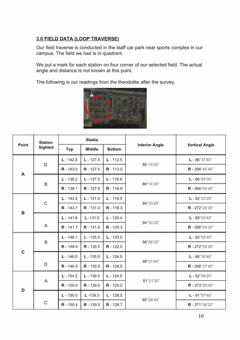
3.0 FIELD DATA (LOOP TRAVERSE)
Our field traverse is conducted in the staff car park near sports complex in our campus. The field we had is in quadrant. We put a mark for each station on four corner of our selected field. The actual angle and distance is not known at this point.
The following is our readings from the theodolite after the survey,
Point Station Sighted
Stadia Interior Angle Vertical Angle
Top Middle Bottom
A
D L 142.6 L 127.5 L 112.5
86°15’00” L 86°37’40”
R 143.0 R 127.5 R 113.0 R 266°45’40”
B L 138.2 L 127.5 L 116.8
86°14’20” L 86°04’00”
R 138.1 R 127.5 R 116.9 R 266°04’40”
B
C L 143.5 L 131.0 L 118.5
94°33’20” L 92°23’20”
R 143.7 R 131.0 R 118.3 R 272°24’00”
A
L 141.6 L 131.0 L 120.4 94°33’20”
L 86°03’40”
R 141.7 R 131.0 R 120.3 R 266°04’20”
C
B L 148.1 L 135.5 L 123.0
98°08’20” L 92°06’40”
R 148.0 R 135.5 R 122.5 R 272°05’20”
D
L 146.5 L 135.5 L 124.5 98°01’40”
L 86°35’40”
R 146.5 R 135.5 R 124.5 R 266°37’40”
D
A L 154.5 L 139.5 L 124.5
81°21’20” L 92°59’20”
R 155.0 R 139.5 R 125.0 R 273°00’00”
C
L 150.0 L 139.5 L 128.5 80°58’40”
L 91°57’40”
R 150.4 R 139.5 R 128.7 R 271°56’20”
10

Step 1: Mean the values of Stadia and Angles The value of difference in stadia, vertical angle and interior angle were averaged from the lefthand side readings and righthand side readings to get a closer accuracy. This table below shows the averaged value of our readings,
Point Station Sighted
Difference in Stadia, S (m) (Top Bottom) Interior Angle Vertical Angle, θ
A D 0.301
86°14’40” 3°18’20”
B 0.213 3°55’40”
B C 0.252
94°29’20” 2°23’40”
A 0.213 3°56’00”
C B 0.253
98°05’00” 2°06’00”
D 0.220 3°23’20”
D A 0.300
81°10’00” 2°59’40”
C 0.216 1°57’00”
Step 2: Calculate the vertical distance between the four points The vertical distance between each points is calculated with the formula.
, where, K S os²(θ) C cos(θ) D = × × c + × D = horizontal distance between survey point and instrument K = multiplying constant given by manufacturer of the theodolite, (normally = 100) S = difference between top stadia and bottom stadia = vertical angle of telescope from the horizontal line when capturing the θ
stadia readings C = additive factor given by manufacturer of the theodolite, (normally = 0)
11

Upon obtaining the horizontal distance, a simple layout diagram was drawn for the traverse site. The distance between the point was averaged to get their mean value. Working Draft, Distance from point A → D = + 000 0.301 cos ² (3°1820") 1 × × ′
= 30.000 m Distance from point A → B = + 000 0.213 cos ² (3°5540") 1 × × ′
= 21.200 m
Distance from point B → C = + 000 0.252 cos² (2°2340") 1 × × ′ = 25.156 m
Distance from point B → A = + 000 0.213 cos² (3°5600") 1 × × ′ = 21.200 m
Distance from point C → B = + 000 0.253 cos² (2°0600") 1 × × ′ = 25.266 m
Distance from point C → D = + 000 0.220 cos² (3°2320") 1 × × ′ = 21.923 m
Distance from point D → A = + 000 0.300 cos² (2°5940") 1 × × ′ = 29.918 m
Distance from point D → C = + 000 0.216 cos ² (1°5700") 1 × × ′ = 21.575 m
12

. Step 3: Field Angles Adjustment Compute the angular error and adjust the interior angles.
Station Field Angles
A 86°14’40”
B 94°29’20”
C 98°05’00”
D 81°10’00”
Sum of all angles, Σ 359°59’00”
The sum of the interior angles in this loop traverse must equal to,
= ( n 2 ) x 180° , where n = number of sides
= ( 4 – 2 ) x 180°
= 360°
13

The total angular error is
= 360° 359°59’00’’
= 1°00’00’’
Therefore, the error per angle is
= 1°00’00” 4÷
= 0°00’15’’ per angle
Errors Correction,
Station Field Angles Correction Adjusted Angles
A 86°14’40” + 0°0’15” 86°14’55”
B 94°29’20” + 0°0’15” 94°29’35”
C 98°05’00” + 0°0’15” 98°05’15”
D 81°10’00” + 0°0’15” 83°10’15”
Sum of all angles, Σ 359°59’00” 360°00’00”
Step 4: Compute Course Azimuths The azimuths is traveling in clockwise direction starting from point A and travel back to the same point A.
Course Azimuths
Assume the line A D is in a 180° straight line, A B,
180°00’00” 86°14’55”
93°45’05”
14

B C,
180°00’00” + 93°45’05” 94°29’35”
179°15’30”
C D,
179°15’30” + 180°00’00” 98°05’15”
261°10’15”
The azimuth cycle 360° from the south to point A. D A,
360°00’00”
Step 5: Latitude and Departure
Compute the course latitude and departure with, (a) LATITUDE = LENGTH x COS β (b) DEPARTURE = LENGTH x SIN β
15

Working Draft, Path from point A → B,
Latitude = 1.200 cos (93°45’05’’) 2 × = 1.3871
Departure = 1.200 sin (93°45’05’’) 2 ×
= 21.1546 Path from point B → C,
Latitude = 5.211 cos (179°15’30”) 2 × = 25.2089
Departure = 5.211 sin (179°15’30”) 2 ×
= 0.3263 Path from point C → D,
Latitude = 1.749 cos (261°10’15’’) 2 × = 3.3382
Departure = 1.749 sin (261°10’15’’) 2 ×
= 21.4913 Path from point D → A,
Latitude = 9.959 cos (360°00’00”) 2 × = 29.959
Departure = 9.959 sin (360°00’00”) 2 ×
= 0
16

The latitude and departure for each station is as followings,
Station Azimuth, β Length, L (m) Cosine β Sine β Latitude Departure A 93°45’05’’ 21.200 0.0654 0.9981 1.3871 21.1546 B
179°15’30” 25.211 0.9999 0.0129 25.2089 0.3263 C
261°10’15’’ 21.749 0.1535 0.9882 3.3382 21.4913
D
360°00’00” 29.959 1.000 0 29.959 0 A
Σ (Perimeter) 98.119
(∑Δy) 0.0248
(∑Δx) 0.0104
Step 5: Error of closure and accuracy Determine the error of closure and accuracy; = ∑Δy² ∑Δx² = √ (0.0248)² + (0.0104)² = 0.0269 Hence, the accuracy is
= 1: (P/ Ec)
= 1: (98.119/0.0269)
= 1: 3647.5465 [> 1: 3000]
∴ ERROR ACCEPTABLE, proceed to adjustment
17

Step 6: Adjust Course Latitudes and Departures The correction can be done with “The Compass Rule”:
= OR , where,ΣΔy] P L − [ ÷ × ΣΔx] P L − [ ÷ ×
and = the error in latitude or in departureΔy Σ Δx Σ = the total length or perimeter of traverseP = the length of particular courseL
Station Unadjusted Corrections Adjusted Latitude Departure Latitude Departure Latitude Departure A
1.3871 21.1546 0.0053 0.0022 1.3924 21.1568
B 25.2089 0.3263 0.0064 0.0027 25.2153 0.3290
C
3.3382 21.4913 0.0055 0.0023 3.3437 21.4890
D
29.959 0 0.0076 0.0032 29.9514 0.0032
A
(∑Δy) 0.0248
(∑Δx) 0.0104
Check 0.0248
0.0104
Check 0.0000
0.0000
Step 7: Station Coordinates Compute the station coordinates with,
N₂ = N₁ + Latitude₁₋₂
E₂ = E₁ + Departure₁₋₂, where, N₂ and E₂ = the Y and X coordinates of station 2
N₁ and E₁ = the Y and X coordinates of station 1
Latitude₁₋₂ = Latitude of course 12
Departure₁₋₂ = Departure of course 12
18

Assuming the point A is on (100,100) coordinates,
Course Adjusted Latitude Adjusted Departure Station N Coordinate
(Latitude y axis) E Coordinate
(Departure x axis)
A 100.0000 100.0000
A B 1.3924 21.1568
B 98.6076 121.1568
B C 25.2153 0.3290
C 73.3923 121.4858
C D 3.3437 21.4890
D 70.0486 99.9968
D A 29.9514 0.0032
A 100.0000 (checked)
100.0000 (checked)
A graph was plotted with the coordinates obtained for each station.
19

Step 8: Table and Graph of complete traverse (not to scale)
20

The complete graph of traversing
Traversing exact location on our field site
21

4.0 SUMMARY
Four points A, B, C and D are being laid on the site respectively by
marking with liquid paper on the floor. The theodolite is being placed at the
first point, A. Then from point A, we measure the reading to point B and D
(set at zero degree). The angles of the points are basically taken from
left to right. After that turn over to measure from right to left.
The survey was done proceed to the remaining point B, C, and D. This
form a complete quadrant for the site survey. All the measurement was
recorded in a table. To ensure a correct measurement is obtained and
reducing the error, we do twice on the survey on each points.
Since our area is a foursided polygon. Henceforth, we can deduce that
the total interior angle is 360° from the formula (n2) x 180°. However, we
only managed to get a total interior angle of 359°59’00’’ as errors has
occurred while taking the readings.
Therefore, we have to make the adjustments by using distributing the
angular errors. Later, we proceed by getting the latitude and departure of
each point. After we found out that our reading accuracy is acceptable by
using the formula, 1: (P/ Ec) , with a value of 1:3647, we continue to
22

closing up the point A and A’ by adjusting the latitude and departure of our
readings by using these two formulae, the compass rule:
[∑Δy]/ ∑ l Latitude l x Cumulative Length ( Latitude )
[∑Δx]/ ∑ l Departure l x Cumulative Length ( Departure )
After the adjustment, thus giving a complete quadrant on the site survey.
We are then continue to find the coordinates and plotting them on a graph,
this help us to get a better understanding on our site survey, with all the
detailed dimensions and measurements.
In conclusion, we have learnt how to use a theodolite in proper way and also
able to get a correct measurement. Our groupmates have also been very
helpful as this task cannot be carried out by one less person especially under
the scorching hot sun. Also special thanks to our Site Surveying lecturer, Mr.
Chai to be always there in the field to guide us and make sure that we carry
out the measurement correctly.
23