Site investigation SFR - Boremap mapping of core drilled ...
23
Svensk Kärnbränslehantering AB Swedish Nuclear Fuel and Waste Management Co Box 250, SE-101 24 Stockholm Phone +46 8 459 84 00 P-09-59 Site investigation SFR Boremap mapping of core drilled borehole KFR105 Sofia Winell, Geosigma AB November 2009
Transcript of Site investigation SFR - Boremap mapping of core drilled ...
Svensk Kärnbränslehantering ABSwedish Nuclear Fueland Waste Management Co
Box 250, SE-101 24 Stockholm Phone +46 8 459 84 00
P-09-59
Site investigation SFR
Boremap mapping of core drilled borehole KFR105
Sofia Winell, Geosigma AB
November 2009
CM
Gru
ppen
AB
, Bro
mm
a, 2
010
Tänd ett lager:
P, R eller TR.
Site investigation SFR
Boremap mapping of core drilled borehole KFR105
Sofia Winell, Geosigma AB
November 2009
ISSN 1651-4416
SKB P-09-59
Keywords: P-report SKBDoc id 1235988, Review statement SKBDoc id 1235980, Appendix SKBDoc id 1235981, Fractures, BIPS, Boremap, Core Drilling, Geophysical logs, SFR, AP SFR-09-012, KFR105, Project SFR extension.
This report concerns a study which was conducted for SKB. The conclusions and viewpoints presented in the report are those of the author. SKB may draw modified conclusions, based on additional literature sources and/or expert opinions.
Data in SKB’s database can be changed for different reasons. Minor changes in SKB’s database will not necessarily result in a revised report. Data revisions may also be presented as supplements, available at www.skb.se.
A pdf version of this document can be downloaded from www.skb.se.
P-09-59 3
Abstract
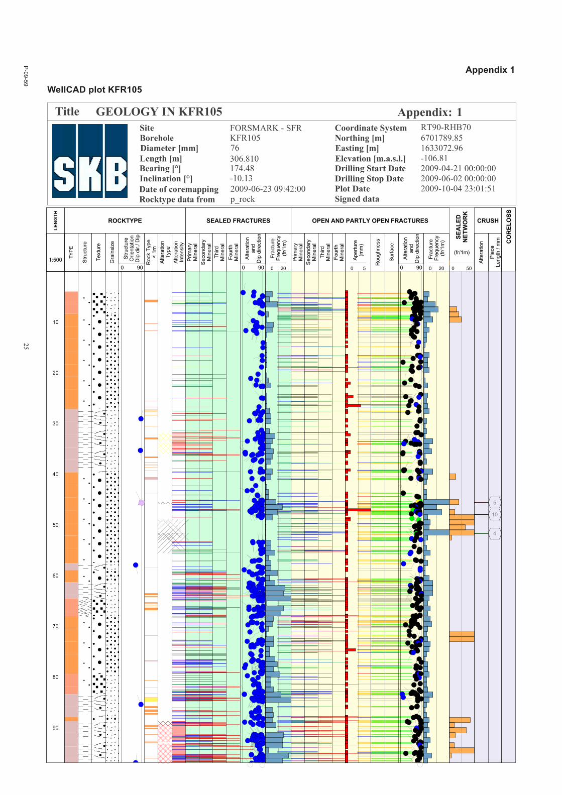
This report presents the result from the Boremap mapping of the core drilled borehole KFR105, which is drilled from the lower construction tunnel within SFR. The borehole has a length of 306.81 m, and a bearing and inclination of 174.5° and –10.1°, respectively.
The borehole KFR105 was drilled with the aim to characterize the bedrock at depths beneath the possible extension of the SFR, and to characterize interpreted low magnetic lineaments.
The geological mapping is based on simultaneous study of drill core and borehole image (BIPS). The upper- and lowermost few meters of the drill core were mapped in Boremap without access to complementary BIPS-image.
The dominating rock types in KFR105 are fine- to medium-grained metagranite-granodiorite (101057) and pegmatite to pegmatitic granite (101061), which occupies 44% and 41% of the mapped interval, respectively. Subordinate rock types are fine- to medium-grained granite (111058), felsic to inter-mediate metavolcanic rock (103076) and one short interval with amphibolite (102076).
About 8% of the rock in KFR105 has been affected by alterations, where oxidation is the most common. Other types of alterations are muscovitization, laumontization, chloritization and argillization.
A total number of 3,400 fractures are registered in KFR105. Of these are 1,101 open, 2,264 sealed and 35 partly open. This result in the following fracture frequencies: 7.4 sealed fractures/m, 3.6 open fractures/m and 0.1 partly open fractures/m. In addition there are 30 sealed networks in KFR105, with a total length of 32 m.
The most frequent fracture fillings in KFR105 are calcite, chlorite, laumontite, quartz and muscovite. Oxidized walls occur along 55% of the fractures.
There are two dominating sets of broken and unbroken fractures with the rough orientations 180°/55° and 170°/00°. Additionally, one subordinate set of unbroken fractures with the orientation 355°/50° is observed.
There are 9 crushed intervals (drill-induced excluded) in KFR105, with a total length of 0.56 m.
4 P-09-59
Sammanfattning
Denna rapport presenterar resultatet från Boremapkarteringen av kärnborrhålet KFR105, vilket är borrat från den nedre byggtunneln i SFR. Borrhålet har en längd på 306,81 m, med en bäring och inklination på 174,5° respektive –10,1°.
Borrhålet borrades med syftet att karaktärisera berget på djupet under en eventuell utbyggnad av SFR, samt att karaktärisera framtolkade lågmagnetiska lineament.
Den geologiska karteringen baseras på simultan undersökning av borrkärna och borrhålsbild (BIPS). Den första och sista metrarna av borrkärnan karterades utan tillgång till BIPS-bild.
De dominerande bergarterna i KFR105 är fin- till medelkornig metagranit-granodiorit (101057) och pegmatit till pegmatitisk granit (101061), vilka upptar respektive 44 % och 41 % av det karterade inter vallet. Underordnade bergarter är fin- till medelkornig granit (111058), felsisk till intermediär metavulkanit (103076) och ett kort intervall med amfibolit (102017).
Cirka 8 % av bergarterna i KFR105 är påverkade av omvandlingar, där oxidation är den vanligaste. Andra typer av omvandlingar är muskovitisering, laumontitisering, kloritisering och leromvandling.
Antalet registrerade sprickor i KFR105 är 3 400 stycken. Av dessa är 1 101 öppna, 2 264 läkta och 35 delvis öppna. Sprickfrekvensen är 7,9 läkta sprickor/m, 3,4 öppna sprickor/m och 0,1 delvis öppna sprickor/meter. Dessutom finns det 30 läkta spricknätverk i KFR105, med en total längd av 32 m.
De vanligaste sprickmineralen i KFR105 är kalcit, klorit, laumontit, kvarts och muskovit. Oxiderat sidoberg förekommer längs 55 % av alla sprickor.
Det finns två dominerande grupper av öppna och läkta sprickor med orienteringen 180°/55° och 170°/00°. Ytterligare en underordnad grupp av läkta sprickor med orienteringen 355°/50° finns.
Det finns 9 sektioner med kross i KFR105 (borrinducerade krossar exkluderade), med en total längd på 0,56 m.
P-09-59 5
Contents
1 Introduction 7
2 Objective and scope 9
3 Equipment 113.1 Description of equipment/interpretation tools 11
3.1.1 Used BIPS-files and image quality 11
4 Execution 134.1 General 134.2 Preparations 134.3 Execution of meaurements 14
4.3.1 Fracture definitions 144.3.2 Fracture alteration and joint alteration number 144.3.3 Mapping of fractures not visible in the BIPS-image 144.3.4 Mineral codes 144.3.5 Foliation and lineation 154.3.6 Alteration 15
4.4 Data handling/post processing 154.5 Nonconformities 15
4.5.1 Drill induced crushes 154.5.2 Underestimated fracture minerals 15
5 Result 175.1 Lithology 17
5.1.1 Alteration 185.1.2 Fractures 18
6 References 21
Appendix 1 WellCAD plot KFR105 23
Appendix 2 Generalized geophysical logs and plots of resampled and calibrated geophysical data from KFR105 31
Appendix 3 In data SICADA – Information about KFR105 33
P-09-59 7
1 Introduction
SKB intends to enlarge the existing repository for low- and intermediate-level radioactive waste in Forsmark (SFR), to be able to host the waste that will arise from demolishing of the nuclear power plants. The existing repository was completed and ready for operation in 1988, and was the first of its kind in the world. The extension is estimated to be ready in 2020.
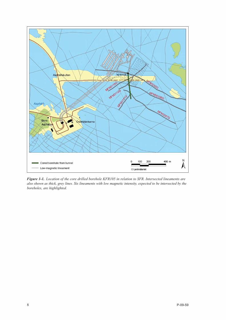
A lot of information about the bedrock and groundwater has already been gathered during the building of SFR, but some complementary studies have to be done. This document reports the data gained by the Boremap mapping of the core drilled borehole KFR105, which is one of the activities performed within the site investigation at SFR. The borehole KFR105 is drilled from the lower construction tunnel within SFR (Figure 1-1), and has a length of 306.81 m, a bearing of 174.5° and an inclination of –10.1° (Appendix 3).
The work was carried out in accordance with activity plan AP SFR-09-012, and controlling documents for this activity are listed in Table 1-1. Both activity plan and method descriptions are SKB’s internal controlling documents.
The core drilled borehole was drilled during the period April to June 2009 and was after completion, investigated with several logging methods, such as conventional geophysical logging and TV-logging. The latter method implies logging with a colour TV-camera to produce images of the borehole wall, so called BIPS-images (Borehole Image Processing System).
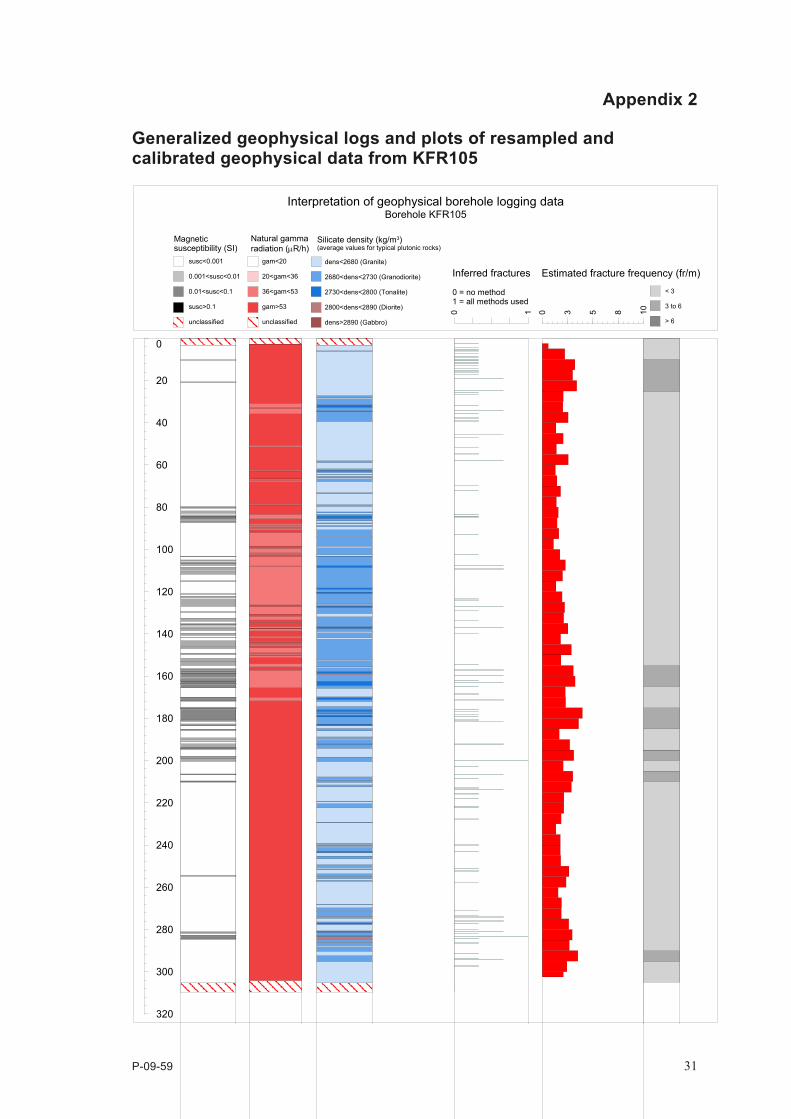
The borehole was mapped in the period June–August 2009. Mapping of cored borehole according to the Boremap method is based on simultaneous study of the drill core and the use of BIPS-images of the borehole wall. The mapping was also supported by generalized geophysical logs (Appendix 2, /10/).
The BIPS-image enables the study of fractures and their characteristics along the borehole. Strike and dip of planar structures such as fractures, foliations and rock contacts are calculated and documented with the Boremap method.
Original data from the reported activity are stored in the primary database Sicada, where they are traceable by the Activity Plan number (AP SFR-09-012). Only data in SKB’s databases are accepted for further interpretation and modelling.
Table 1‑1. Controlling documents for the performance of the activity.
Activity plan Number VersionBoremapkartering av kärnborrhål KFR105 AP SFR-09-012 1.0
Method descriptions Number VersionMetodbeskrivning för Boremapkartering SKB MD 143.006 2.0Metodbeskrivning för TV-loggning med BIPS SKB MD 222.006 2.0Mätsystembeskrivning för Boremap SKB MD 146.005 1.0Instruktion: Regler för bergarters benämningar vid platsundersökningen i Forsmark
SKB MD 132.005 1.0
8 P-09-59
Figure 1‑1. Location of the core drilled borehole KFR105 in relation to SFR. Intersected lineaments are also shown as thick, grey lines. Six lineaments with low magnetic intensity, expected to be intersected by the boreholes, are highlighted.
P-09-59 9
2 Objective and scope
The borehole KFR105 was drilled with the aim to characterize the bedrock at depths beneath the possible extension of SFR, and to characterize lineaments with low magnetic intensity. The location of the bore hole makes it also possible to gather valuable hydrological and hydrochemical information about the bedrock, and to verify the geohydrological model. Lithologies, alterations, ductile structures and the occurrence and character of fractures in the bedrock penetrated by KFR105 were documented. Other data, such as thickness of soil cover, soil stratigraphy, groundwater level and groundwater flow will not be treated in this report.
P-09-59 11
3 Equipment
3.1 Description of equipment/interpretation toolsMapping of the borehole based on BIPS-image was performed with the software Boremap v.3.9.6.4. Boremap software is loaded with the rock types and mineral standard used for surface mapping at the Forsmark site investigation, in order to enable correlation with the surface geology. Inclination, bearing and diameter of the borehole are used as in-data for the calculations. The BIPS-image length deviates from the true borehole length with increasing depth. Length adjustments are therefore made on the basis of reference marks cut into the borehole wall after drilling.
Schematic presentations of the boreholes are presented in WellCAD-diagrams (Appendix 1).
Equipment used to facilitate the core mapping are folding rule, 10% hydrochloric acid, rock hardness tool, hand lens, paint brush and tap water.
3.1.1 Used BIPS‑files and image qualityInformation about Used BIPS-files is listed in Table 3-1.
The following factors may disturb the mapping:
• Brownishcoatingsprobablyrelatedtothedrillingequipment.
• Verticalelongationofpixelsduetostick-slipmovementofthecameraprobe.
The BIPS-image quality of the borehole KFR105 is generally good. A more or less transparent and continuous vertical band with brownish coating is observed along the entire BIPS-image.
In the interval 228–242 m, vertical elongations of pixels displace features in the BIPS-image. The biggest difference between measured length in core and BIPS-image is 18 cm, measured for a fracture at 242.005 m adjusted length. The same problem occurs around 249 m. The measured difference between measured core length and BIPS-image is 12.5 cm for a fracture at 249.03 m, adjusted length.
The results from the BIPS-loggings are presented in /1/. The intervals 0.00–4.00 and 304.66–306.80 m of KFR105 were mapped without any complementary BIPS-image.
Table 3‑1. Used BIPS‑file.
Borehole BIPS‑file Logging date Logging time (start)
From recorded length (m)
To recorded length (m)
KFR105 KFR105_4-303m_20090616.BIP 2009-06-16 12:16 4 303.492
P-09-59 13
4 Execution
4.1 GeneralBoremap mapping of the core drilled borehole KFR105 was performed and documented according to activity plan AP SFR-09-012 (SKB, internal document). Geophysical logs of the borehole supported the mapping (Appendix 2, /10/). The mapping was performed in accordance with the current SKB method descriptions (Table 1-1) and /2/. Information from earlier performed investigations in the area were also helpful in the interpretations /3, 4, 5, 6, 7/.
4.2 PreparationsBackground data collected from Sicada (Appendix 3) prior to the Boremap mapping included:
• objectinformation,
• boreholedeviationdata,
• boreholediameter,
• referencemarksindrillhole.
These background data, except for borehole diameter, are imported from Sicada by semiautomatic routines.
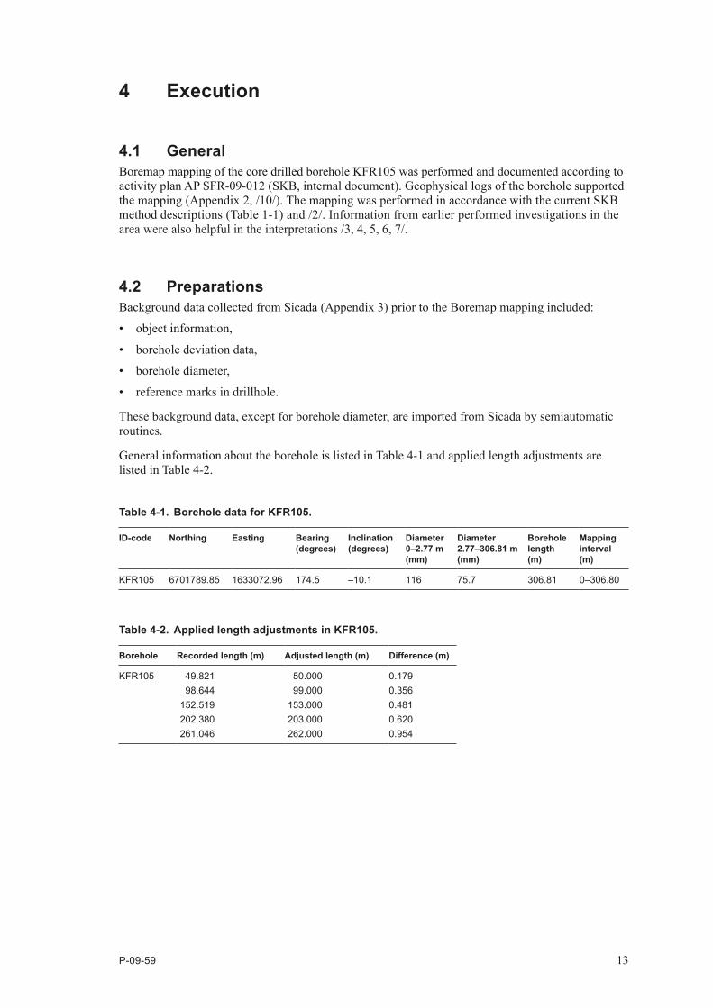
General information about the borehole is listed in Table 4-1 and applied length adjustments are listed in Table 4-2.
Table 4‑1. Borehole data for KFR105.
ID‑code Northing Easting Bearing (degrees)
Inclination (degrees)
Diameter 0–2.77 m (mm)
Diameter 2.77–306.81 m (mm)
Borehole length (m)
Mapping interval (m)
KFR105 6701789.85 1633072.96 174.5 –10.1 116 75.7 306.81 0–306.80
Table 4‑2. Applied length adjustments in KFR105.
Borehole Recorded length (m) Adjusted length (m) Difference (m)
KFR105 49.821 50.000 0.17998.644 99.000 0.356
152.519 153.000 0.481202.380 203.000 0.620261.046 262.000 0.954
14 P-09-59
4.3 Execution of meaurements4.3.1 Fracture definitionsDefinitions of different fracture types and apertures, crush zones and sealed fracture network are found in SKB MD 143.008 and “Kalibrering av Boremapkartering” (v.0.9) which is planned to be implemented in the next version of SKB MD 143.006.
Two types of fractures, broken and unbroken, are registered in Boremap depending on whether the core is split through the core axis or not. All fractures are described with their fracture minerals, width, aperture and roughness. To decide whether a fracture was open, partly open or sealed prior to drilling the aperture confidence is expressed as “certain”, “probable” or “possible”. The confidence level depends on weather-ing of fracture surfaces and fit of the core pieces.
All fractures with aperture > 0 mm are registered as open or partly open and all fractures with aperture = 0 mm are registered as sealed in the Sicada database. Normally, unbroken fractures have apertures = 0 and broken apertures > 0 mm. However, unbroken fractures with voids, for example, have aperture > 0. Broken fractures considered artificial have aperture = 0. The frequency of open and sealed fractures are calculated and shown in the WellCAD-diagram (Appendix 1).
4.3.2 Fracture alteration and joint alteration numberJoint alteration number is mainly related to the thickness and clay content of the mineral fillings /8/. Fractures that are more than 1 mm wide and rich in clay minerals are usually given joint alteration numbers between 2 and 4. The majority of the broken fractures are very thin to extremely thin and seldom contain clay minerals, or very small amounts of clay and chlorite. These fractures have joint alteration numbers between 1 and 2. Since most fractures are within this span, a subdivision with joint alteration number = 1.5 was performed to facilitate both the evaluation process for fracture alterations, and the possibility to compare the alterations between different fractures in the boreholes The use of joint alteration number 1.5 is a remnant from the Forsmark site investigation project.
4.3.3 Mapping of fractures not visible in the BIPS‑imageFractures not visible in the BIPS-image are oriented using the guideline method /9/. The orientation performed in this work is based on the following data:
• Amplitude(measuredalongthedrillcore),whichisthelengthbetweenfractureextremesalongthe drill core.
• Therelationbetweentherotationofthefracturetraceandawelldefinedstructurevisibleinbothdrill core and BIPS-image. This rotation is measured with measuring tape on the drill core.
• AbsoluteboreholelengthrelativetoawelldefinedstructurevisibleinbothdrillcoreandBIPS-image.
The fractures mapped with the guideline method are registered in Boremap as “non-visible in BIPS”.
4.3.4 Mineral codesIn cases where properties or minerals are not represented in the mineral list, the following mineral codes have been used in the mapping of KFR105:
• X1=Bleachedfracturewalls.
• X3=Thedrillcoreisbrokenatarightangle,andthebrokensurfaceshaveapolishedappearance.This is caused by rotation of two core pieces along an intermediate fracture wearing away possible mineral filling. It is impossible to decide whether this fracture was open or sealed in situ.
P-09-59 15
4.3.5 Foliation and lineationThe metagranite-granodiorite, which occupies most of the area in Forsmark are usually LS tectonites, where lineation dominates over foliation /4/. In the SFR-area, the foliation is usually dominating in the metagranite-granodiorite and therefore it is mostly foliation that is mapped. In the SFR area there are also signs of folding, resulting in varying intensity of the foliation and lineation. An estimated average intensity is mapped for rock types.
The higher strain in the SFR-area relative to the candidate area of the Forsmark site investigation, also appears in the somewhat finer grain-size of the metagranite-granodiorite, which is mapped as “fine- to medium-grained” in the SFR-area.
4.3.6 AlterationThe term “muscovitization” is not in the Boremap system and is mapped as sericitization with a comment “muscovite”.
4.4 Data handling/post processingThe Boremap mapping of KFR105 was performed on SKB’s network, while a backup was saved on a local computer before each break exceeding 15 minutes. When the mappings were finished and quality checked by the operator and by a routine in Boremap, the data was submitted to SKB for exportation to Sicada.
All data are stored in Sicada, and it is only these data that should be used for further interpretation.
The data presented in this report are regarded as copies of the original data. Data in the databases may be revised, if needed. Such revisions will not necessarily result in a revision of the P-report, although the normal procedure is that major revisions entail a revision of the P-report. Minor revisions are normally presented as supplements, available at www.skb.se.
4.5 Nonconformities4.5.1 Drill induced crushesThere are 16 drill induced crushes registered in KFR105, with at total length of 0.7 m.
4.5.2 Underestimated fracture mineralsDue to the reaction of calcite with hydrochloric acid, and the strong colouration of other minerals by hematite, these two minerals are detected even though they are macroscopically invisible. Minerals present in the same fracture as calcite and hematite run the risk of getting underestimated, as well as less conspicuous minerals in other fractures. To partly reduce this problem, hematite has only been mapped if a red streak is observed; otherwise it is considered to occur only as pigmentation.
P-09-59 17
5 Result
The data from Boremap mapping of KFR105 is stored in Sicada, and it is only these data that shall be used for further interpretation and modelling. The user of this data should be aware of the assumptions mentioned in Chapter 4. Graphical presentations of the data are given as WellCAD-diagrams in Appendix 1. A summary of rock types and fracture frequency in the borehole is presented in Table 5-1 and 5-2.
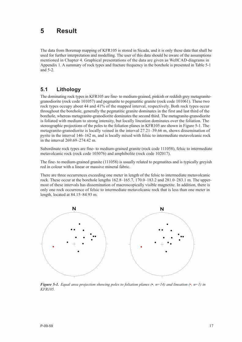
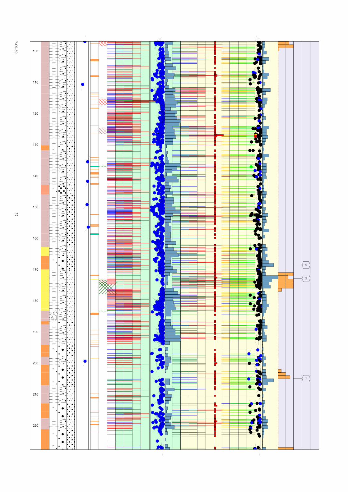
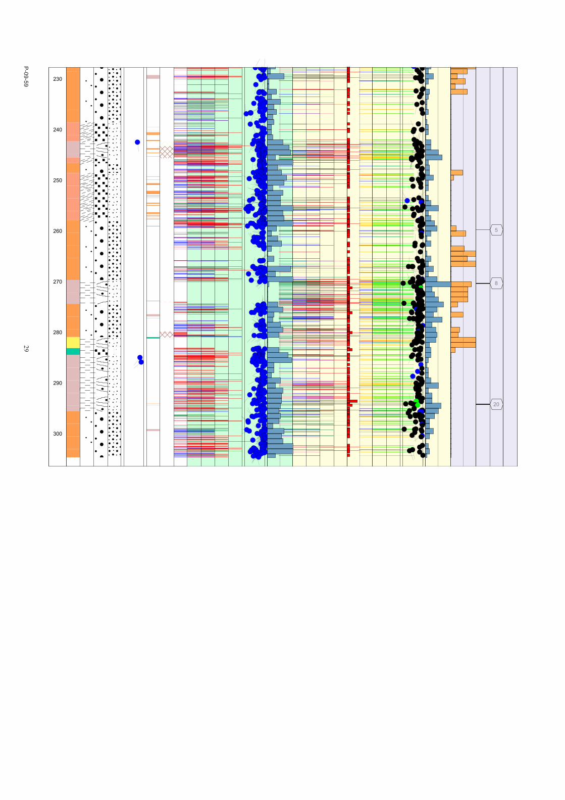
5.1 LithologyThe dominating rock types in KFR105 are fine- to medium-grained, pinkish or reddish grey metagranite-granodiorite (rock code 101057) and pegmatite to pegmatitic granite (rock code 101061). These two rock types occupy about 44 and 41% of the mapped interval, respectively. Both rock types occur through out the borehole, generally the pegmatitic granite dominates in the first and last third of the borehole, whereas metagranite-granodiorite dominates the second third. The metagranite-granodiorite is foliated with medium to strong intensity, but locally lineation dominates over the foliation. The stereographic projections of the poles to the foliation planes in KFR105 are shown in Figure 5-1. The metagranite-granodiorite is locally veined in the interval 27.21–39.66 m, shows dissemination of pyrite in the interval 146–162 m, and is locally mixed with felsic to intermediate metavolcanic rock in the interval 269.69–274.42 m.
Subordinate rock types are fine- to medium-grained granite (rock code 111058), felsic to intermediate metavolcanic rock (rock code 103076) and amphibolite (rock code 102017).
The fine- to medium-grained granite (111058) is usually related to pegmatites and is typically greyish red in colour with a linear or massive mineral fabric.
There are three occurrences exceeding one meter in length of the felsic to intermediate metavolcanic rock. These occur at the borehole lengths 162.8–165.7, 170.0–183.2 and 281.0–283.1 m. The upper-most of these intervals has dissemination of macroscopically visible magnetite. In addition, there is only one rock occurrence of felsic to intermediate metavolcanic rock that is less than one meter in length, located at 84.15–84.93 m.
Figure 5‑1. Equal area projection showing poles to foliation planes (•, n=14) and lineation (•, n=1) in KFR105.
18 P-09-59
The only occurrence of amphibolite exceeding one meter in length occurs at 283.14–284.50 m. In addition, there are five minor occurrences of amphibolite at 136.87–137.17, 158.46–158.94, 277.26–277.35, 280.78–280.82 and 280.96–281.25 m, of which the second one has disseminations of macroscopically visible magnetite and pyrite.
The rock type distribution in KFR105 is presented in Table 5-1.
Rock occurrences (rock types < 1 m in length) occupy about 9% of the logged drill core. Dykes, veins and unspecified occurrences of pegmatite and pegmatitic granite dominate, where the majority of them are less than 1 dm in width. Except for rock occurrences of the rock types in Table 5-1, quartz dominated veins (rock code 8021), undifferentiated granite (rock code 1058), breccia (rock code 6005) and one occurrence of cataclastic rock (8003) are registered.
Only two narrow deformation zones of ductile character are registered in KFR105. These are located at 293.571–293.584 and 158.681–158.699 m.
5.1.1 AlterationIn KFR105 about 8% of the borehole length has been registered as altered, and the most common altera-tion is oxidation. Four sections of oxidation exceeds one meter in length: 88.7–98.2 (not continuously), 115.3–117.2, 124.5–126.4 and 243.3–245.5 m. In addition 1,882 fractures are mapped with oxidized walls.
There are two intervals of muscovitization at 32.0–35.9 and 242.3–245.0 m. As muscovite alteration is not in the boremap system, it is registered as sericitization. The muscovite seems to replace biotite in the foliation planes and is most likely of metamorphic origin, and hence not related to any brittle structures.
Additional alterations are limited to less extensive intervals and include argillization, laumontization and chloritization. Argillization is mapped for three short sections within the interval 45–52 m, and laumontization in the sections 172.8–173.2 (not continuously), 274.0–274.1 and 279.8–280.45 m. Chloritization is localized to a rock occurrence of amphibolite at 136.9–137.2 m and to shorter sections in felsic to intermediate volcanic rock within the interval 173.3–174.9 m, and continuously for the interval at 183.2-183.4 m.
5.1.2 FracturesA total number of 3,400 fractures are registered in KFR105. Of these are 1,101 open (broken with aperture > 0), 2,264 sealed (broken and unbroken fractures with aperture = 0) and 35 are partly open (unbroken fractures with aperture > 0). This result in the following fracture frequencies: 7.4 sealed fractures/m (sealed fractures in sealed fracture networks are excluded), 3.6 open fractures/m (crushes excluded) and 0.1 partly open fractures/m (Table 5-2).
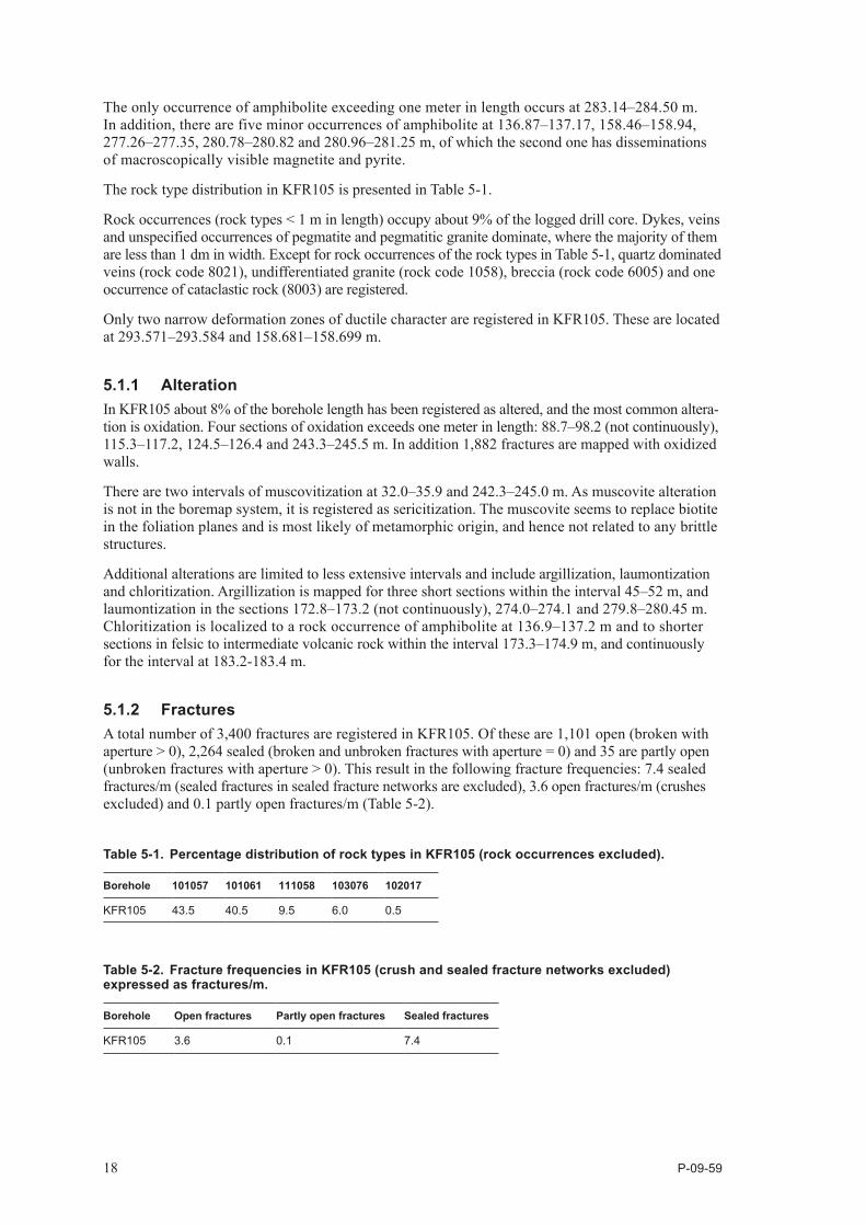
Table 5‑2. Fracture frequencies in KFR105 (crush and sealed fracture networks excluded) expressed as fractures/m.
Borehole Open fractures Partly open fractures Sealed fractures
KFR105 3.6 0.1 7.4
Table 5‑1. Percentage distribution of rock types in KFR105 (rock occurrences excluded).
Borehole 101057 101061 111058 103076 102017
KFR105 43.5 40.5 9.5 6.0 0.5
P-09-59 19
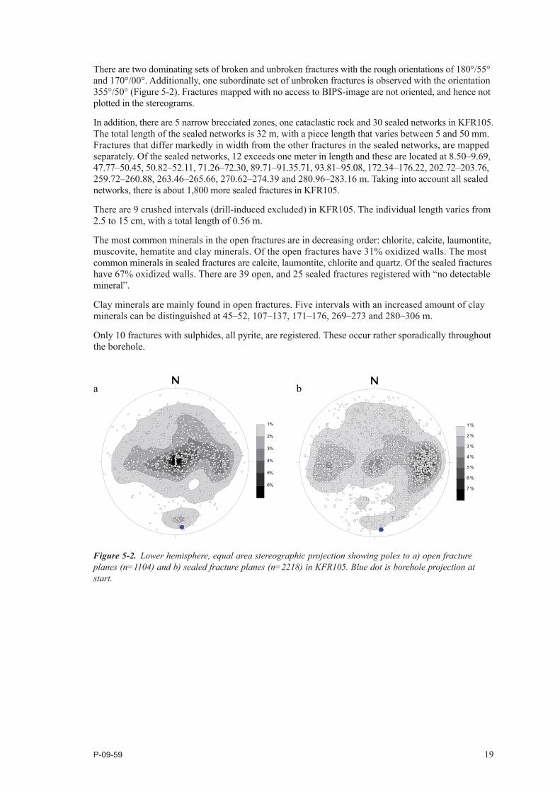
There are two dominating sets of broken and unbroken fractures with the rough orientations of 180°/55° and 170°/00°. Additionally, one subordinate set of unbroken fractures is observed with the orientation 355°/50° (Figure 5-2). Fractures mapped with no access to BIPS-image are not oriented, and hence not plotted in the stereograms.
In addition, there are 5 narrow brecciated zones, one cataclastic rock and 30 sealed networks in KFR105. The total length of the sealed networks is 32 m, with a piece length that varies between 5 and 50 mm. Fractures that differ markedly in width from the other fractures in the sealed networks, are mapped separately. Of the sealed networks, 12 exceeds one meter in length and these are located at 8.50–9.69, 47.77–50.45, 50.82–52.11, 71.26–72.30, 89.71–91.35.71, 93.81–95.08, 172.34–176.22, 202.72–203.76, 259.72–260.88, 263.46–265.66, 270.62–274.39 and 280.96–283.16 m. Taking into account all sealed networks, there is about 1,800 more sealed fractures in KFR105.
There are 9 crushed intervals (drill-induced excluded) in KFR105. The individual length varies from 2.5 to 15 cm, with a total length of 0.56 m.
The most common minerals in the open fractures are in decreasing order: chlorite, calcite, laumontite, muscovite, hematite and clay minerals. Of the open fractures have 31% oxidized walls. The most common minerals in sealed fractures are calcite, laumontite, chlorite and quartz. Of the sealed fractures have 67% oxidized walls. There are 39 open, and 25 sealed fractures registered with “no detectable mineral”.
Clay minerals are mainly found in open fractures. Five intervals with an increased amount of clay minerals can be distinguished at 45–52, 107–137, 171–176, 269–273 and 280–306 m.
Only 10 fractures with sulphides, all pyrite, are registered. These occur rather sporadically throughout the borehole.
Figure 5‑2. Lower hemisphere, equal area stereographic projection showing poles to a) open fracture planes (n=1104) and b) sealed fracture planes (n=2218) in KFR105. Blue dot is borehole projection at start.
a b
1 %
2 %
3 %
4 %
5 %
6 %
1 %
2 %
3 %
4 %
5 %
6 %
7 %
P-09-59 21
6 References
/1/ Gustafsson J, Gustafsson C, 2010. Site investigation SFR. Radar and BIPS loggings in KFR105, KFR106 and HFR106. SKB P-09-58, Svensk Kärnbränslehantering AB.
/2/ Stråhle A, 2001. Definition och beskrivning av parametrar för geologisk, geofysisk och berg-mekanisk kartering av berg. SKB R-01-19, Svensk Kärnbränslehantering AB.
/3/ Stephens M B, Lundqvist S, Bergman T, Andersson J, Ekström M, 2003. Forsmark site investigation. Bedrock mapping – Rock types, their petrographic and geochemical charac-teristics, and a structural analysis of the bedrock based on Stage 1 (2002) surface data. SKB P-03-75, Svensk Kärnbränslehantering AB.
/4/ Stephens M B, Fox A, La Pointe P, Simeonov A, Isaksson H, Hermansson J, Öhman J, 2007. Geology Forsmark. Site descriptive modelling Forsmark stage 2.2. SKB R-07-45, Svensk Kärnbränslehantering AB.
/5/ Döse C, Stråhle A, Mattsson K-J, Carlsten S, 2009. Site investigation SFR – Investigations. Boremap mapping of core drilled borehole KFR101. SKB P-09-36, Svensk Kärnbränsle hantering AB.
/6/ Döse C, Winell S, Stråhle A, Carlsten S, 2009. Site investigation SFR – Investigations. Bore map mapping of core drilled boreholes KFR102B and KFR103. SKB P-09-38, Svensk Kärnbränslehantering AB.
/7/ Winell S, Döse C, Stråhle A, Selnert E, Carlsten S, 2009. Site investigation SFR – Investigations. Boremap mapping of core drilled boreholes KFR104 and KFR27 (from 147.5 m). SKB P-09-39, Svensk Kärnbränslehantering AB.
/8/ Barton N, 2002. Some new Q-value correlations to assist in site characterization and tunnel design. International Journal of Rock Mechanics and Mining Sciences Vol 39 (2002), pp 185–216.
/9/ Ehrenborg J, Steiskal V, 2004. Oskarshamn Site Investigation. Boremap mapping of core drilled boreholes KSH01A and KSH01B. SKB P-04-01, Svensk Kärnbränslehantering AB.
/10/ Mattson H, Keisu M, 2009. Site investigation SFR – Investigations. Interpretation of geophysical borehole measurements from KFR105, KFR106 and HFR106. SKB P-09-57, Svensk Kärnbränsle-hantering AB. In prep.
P-09-59
23
Granite, fine- to medium-grained
Pegmatite, pegmatitic granite
Granitoid, metamorphic
Granite, granodiorite and tonalite, metamorphic, fine- to medium-grained
Granite, metamorphic, aplitic
Granite to granodiorite, metamorphic, medium-grained
Granodiorite, metamorphic
Tonalite to granodiorite, metamorphic
Diorite, quarts diorite and gabbro, metamorphic
Ultramafic rock, metamorphic
Amphibolite
Calc-silicate rock (skarn)
Magnetite mineralization associated with calc-silicate rock (skarn)
Sulphide mineralization
Felsic to intermediate volcanic rock, metamorphic
Mafic volcanic rock, metamorphic
Sedimentary rock, metamorphic
Cataclastic rock
Biotite
Hematite
Calcite
Chlorite
Quartz
Muscovite
Clay Minerals
Laumontite
No intensity
Faint
Weak
Medium
Strong
Cataclastic
Schistose
Gneissic
Mylonitic
Ductile Shear Zone
Brittle-Ductile Zone
Veined
Banded
Massive
Foliated
Brecciated
Lineated
Hornfelsed
Porphyritic
Ophitic
Equigranular
Augen-Bearing
Unequigranular
Metamorphic
Aphanitic
Fine-grained
Fine to medium grained
Medium to coarse grained
Coarse-grained
Medium-grained
Oxidized
Chloritisized
Epidotisized
Weathered
Tectonized
Sericitisized
Quartz dissolution
Silicification
Argillization
Albitization
Carbonatization
Saussuritization
Steatitization
Uralitization
Laumontitization
Fract zone alteration
Planar
Undulating
Stepped
Irregular
Rough
Smooth
Slickensided
Highly Altered
Completely Altered
Gouge
Fresh
Slightly Altered
Moderately Altered
Slightly Altered
Moderately Altered
Highly Altered
Completley Altered
Gouge
Fresh
STRUCTURE ORIENTATION
Cataclastic
Brecciated
Bedded
Schistose
Mylonitic
Foliated
Lineated
Veined
Ductile Shear Zone
Banded
Brittle-Ductile Shear Zone
Gneissic
STRUKTURE ORIENTATION
Signed data
GRAINSIZE
SURFACE
FRACTURE DIRECTION
ROCK ALTERATION INTENSITY
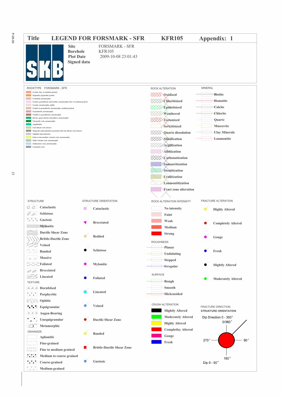
Title LEGEND FOR FORSMARK - SFR KFR105
CRUSH ALTERATION
Borehole KFR105 Site FORSMARK - SFR
ROUGHNESS
Appendix: 1
ROCKTYPE FORSMARK - SFR
FRACTURE ALTERATIONSTRUCTURE
Plot Date 2009-10-08 23:01:43
MINERALROCK ALTERATION
TEXTURE
Page 1
P-09-59
25
Appendix 1
WellCAD plot KFR105
Signed dataDate of coremapping 2009-06-23 09:42:00
Coordinate System RT90-RHB70
Length [m] 306.810
Title GEOLOGY IN KFR105
Diameter [mm] 76Elevation [m.a.s.l.] -106.81
Borehole KFR105
Inclination [°] -10.13
Site FORSMARK - SFR Northing [m] 6701789.85Easting [m] 1633072.96
Appendix: 1
Drilling Stop Date 2009-06-02 00:00:00Plot Date 2009-10-04 23:01:51
Bearing [°] 174.48
Rocktype data from p_rock
Drilling Start Date 2009-04-21 00:00:00
1:500
LEN
GTH
TYP
E
Stru
ctur
e
Text
ure
Gra
insi
ze
Stru
ctur
eO
rient
atio
nD
ip d
ir./ D
ip
0 90
Roc
k Ty
pe<
1mA
ltera
tion
Type
Alte
ratio
nIn
tens
ity
ROCKTYPE
Prim
ary
Min
eral
Sec
onda
ryM
iner
alTh
irdM
iner
alFo
urth
Min
eral
Alte
ratio
nan
dD
ip d
irect
ion
0 90Fr
actu
reFr
eque
ncy
(fr/1
m)
0 20
SEALED FRACTURES
Prim
ary
Min
eral
Sec
onda
ryM
iner
alTh
irdM
iner
alFo
urth
Min
eral
Rou
ghne
ss
Sur
face
Alte
ratio
nan
dD
ip d
irect
ion
0 90
Ape
rture
(mm
)
0 5
Frac
ture
Fr
eque
ncy
(fr/1
m)
0 20
OPEN AND PARTLY OPEN FRACTURES
Alte
ratio
n
Pie
ceLe
ngth
/ m
m
CRUSH
(fr/1m)
0 50
SEA
LED
NET
WO
RK
CO
REL
OSS
10
20
30
40
50
60
70
80
90
5
10
4
Page 1
P-09-59
27
100
110
120
130
140
150
160
170
180
190
200
210
220
5
3
7
Page 2
P-09-59
29
230
240
250
260
270
280
290
300
5
8
20
Page 3
P-09-59 31
Appendix 2
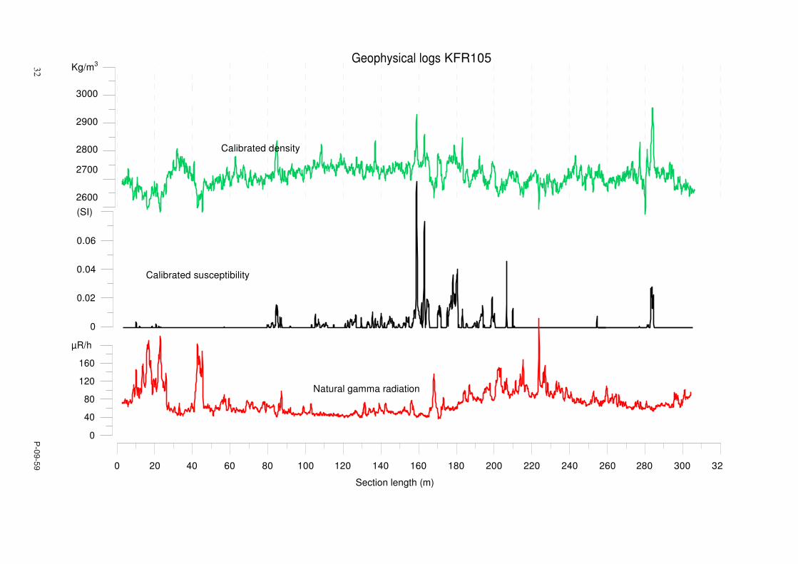
Generalized geophysical logs and plots of resampled and calibrated geophysical data from KFR105
320
300
280
260
240
220
200
180
160
140
120
100
80
60
40
20
0
Interpretation of geophysical borehole logging dataBorehole KFR105
108530
Estimated fracture frequency (fr/m)< 3
3 to 6
> 6
10
Inferred fractures
0 = no method1 = all methods used
Natural gammaradiation ( R/h)
gam<20
20<gam<36
36<gam<53
gam>53
unclassified
Magnetic susceptibility (SI)
susc<0.001
0.001<susc<0.01
0.01<susc<0.1
susc>0.1
unclassified
Silicate density (kg/m3)(average values for typical plutonic rocks)
dens<2680 (Granite)
2680<dens<2730 (Granodiorite)
2730<dens<2800 (Tonalite)
2800<dens<2890 (Diorite)
dens>2890 (Gabbro)
32 P
-09-59
Calibrated susceptibility
Kg/m3 Geophysical logs KFR105
3000
2900
2800 Calibrated density
2700
2600
(SI)
0.06
0.04
0.02
0
µR/h
160
120
80
40
0
Natural gamma radiation
0 20 40 60 80 100 120 140 160 180 200 220 240 260 280 300 32
Section length (m)
P-09-59 33
Appendix 3
In dataSICADA – Information about KFR105
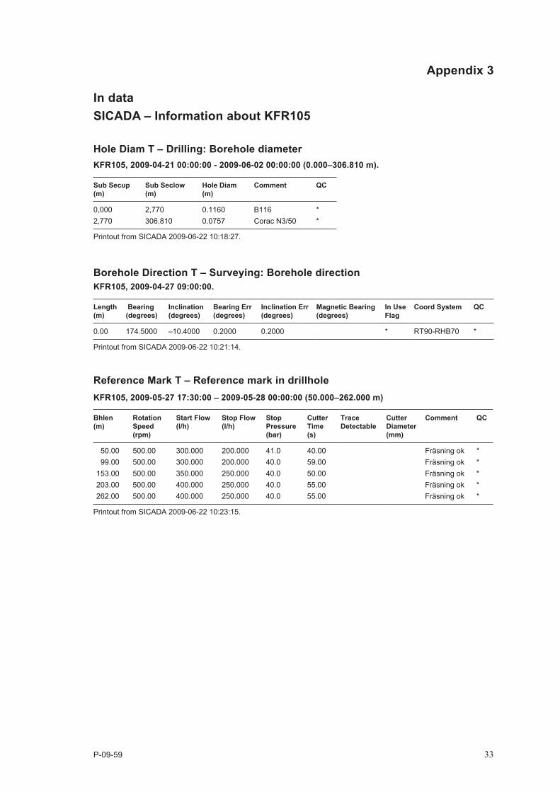
Hole Diam T – Drilling: Borehole diameterKFR105, 2009‑04‑21 00:00:00 ‑ 2009‑06‑02 00:00:00 (0.000–306.810 m).
Sub Secup (m)
Sub Seclow (m)
Hole Diam (m)
Comment QC
0,000 2,770 0.1160 B116 *2,770 306.810 0.0757 Corac N3/50 *
Printout from SICADA 2009-06-22 10:18:27.
Borehole Direction T – Surveying: Borehole directionKFR105, 2009‑04‑27 09:00:00.
Length (m)
Bearing (degrees)
Inclination (degrees)
Bearing Err (degrees)
Inclination Err (degrees)
Magnetic Bearing (degrees)
In Use Flag
Coord System QC
0.00 174.5000 –10.4000 0.2000 0.2000 * RT90-RHB70 *
Printout from SICADA 2009-06-22 10:21:14.
Reference Mark T – Reference mark in drillholeKFR105, 2009‑05‑27 17:30:00 – 2009‑05‑28 00:00:00 (50.000–262.000 m)
Bhlen (m)
Rotation Speed (rpm)
Start Flow (l/h)
Stop Flow (l/h)
Stop Pressure (bar)
Cutter Time (s)
Trace Detectable
Cutter Diameter (mm)
Comment QC
50.00 500.00 300.000 200.000 41.0 40.00 Fräsning ok *99.00 500.00 300.000 200.000 40.0 59.00 Fräsning ok *
153.00 500.00 350.000 250.000 40.0 50.00 Fräsning ok *203.00 500.00 400.000 250.000 40.0 55.00 Fräsning ok *262.00 500.00 400.000 250.000 40.0 55.00 Fräsning ok *
Printout from SICADA 2009-06-22 10:23:15.