SISTEM LIF M E K A N I K A L -...
116
KERAJAAN MALAYSIA JABATAN KERJA RAYA DOKUMEN PEROLEHAN PIAWAI SISTEM LIF M E K A N I K A L CAWANGAN KEJURUTERAAN MEKANIKAL, IBU PEJABAT JKR MALAYSIA, CENTREPOINT NORTH, MID VALLEY CITY, 59200 KUALA LUMPUR. 2011 JKR 20500-0011-10
Transcript of SISTEM LIF M E K A N I K A L -...

KERAJAAN MALAYSIA JABATAN KERJA RAYA
DOKUMEN PEROLEHAN PIAWAI
SISTEM LIF
M E K A N I K A L
CAWANGAN KEJURUTERAAN MEKANIKAL,
IBU PEJABAT JKR MALAYSIA,
CENTREPOINT NORTH,
MID VALLEY CITY,
59200 KUALA LUMPUR.
2011
JKR 20500-0011-10

TABLE OF CONTENTS
DESCRIPTIONS 1. SECTION 1 PREAMBLES
2. SECTION 2 GENERAL SPECIFICATION
3. SECTION 3 TECHNICAL SPECIFICATION
4. SECTION 4 SPECIFICATION FOR TESTING AND COMMISSIONING (T&C)
5. SECTION 5 SPECIFICATION FOR SERVICE AND MAINTENANCE
6. SECTION 6 SCHEDULE OF DESIGN REQUIREMENTS
7. SECTION 7 TECHNICAL DATA FOR EQUIPMENT OFFERED
8. SECTION 8 SCHEDULE OF PRICES
9. SECTION 9 SCHEDULE OF RATES
10. SECTION 10 OTHER REQUIREMENTS (N/A) 11. SECTION 11 LIST OF DRAWINGS

SECTION 1:
PREAMBLES

SECTION 2:
GENERAL SPECIFICATION

SECTION 2 - GENERAL SPECIFICATION
SPECIFICATION OF WORKMANSHIP AND MATERIALS REQUIRED FOR THE SUPPLY AND
INSTALLATION OF ELECTRICAL LIFT SYSTEM
TABLE OF CONTENTS
Page No.
2.1 EXTENT OF CONTRACT 1
2.2 CONDITIONS OF CONTRACT 1
2.3 TENDERS 1
2.4 INSTRUCTION TO TENDERERS 1
2.5 DRAWINGS 2
2.6 APPOINTMENT OF PROFESSIONAL ENGINEER 3
2.7 REGULATIONS 3
2.8 RESPONSIBILITIES OF THE CONTRACTOR AND SUB-CONTRACTOR 3
2.9 SCHEDULE OF WORK 4
2.10 WORKMANSHIP 5
2.11 OBVIOUS WORK 5
2.12 MATERIALS 5
2.13 SITE MEETINGS 5
2.14 ACCESS TO SITE 5
2.15 SUPERVISION 5
2.16 OPERATING INSTRUCTIONS AND TUITION 6
2.17 REPAIR MANUALS AND SPARE PARTS 6
2.18 TOOLS 6
2.19 TESTING AND COMMISSIONING 6
2.20 MAINTENANCE AND GUARANTEE 6
2.21 SERVICE CONTRACT 7
2.22 PROPRIETARY NAMES AND ALTERNATIVE OFFERS 7
2.23 SCHEDULE OF PRICES 7
2.24 SCHEDULE OF RATES 7


Cawangan Kejuruteraan Mekanikal – Edition 1
2. General Specification © Copyright CKM 2010 Page 1
SECTION 2 - GENERAL SPECIFICATION
SPECIFICATION OF WORKMANSHIP AND MATERIALS REQUIRED FOR
THE SUPPLY AND INSTALLATION OF ELECTRICAL LIFT SYSTEM
2.1 EXTENT OF CONTRACT
The work covered by this specification is for the supply of all materials, appliances, labour, and necessary incidentals for the complete installation, testing and commissioning of Lift System as described further in the Specification. This Lift System must be complete in all aspect when handed over to the Jabatan Kerja Raya, and must be in strict accordance to this specification.
2.2 CONDITIONS OF CONTRACT
Tenderers shall read in conjunction with the specification in the following Forms:- (a) Form PWD 203A - Rev. 10/83 (b) Form PWD 203N - Rev. 10/83
The conditions and terms stated in these Forms constitute part of this Specification. Copies of these Forms are available for inspection at the Ibu Pejabat JKR, Jalan Sultan Salahuddin, Kuala Lumpur during normal office hours. The successful tenderer will be required to enter into a sub-contract with the Contractor as nominated Sub-Contractor in accordance with the Conditions of Contract in Form PWD 203N Rev. 10/83 and tenderer is to allow for complying with all the terms and conditions stated in Form 203A - Rev. 10/83 and Form PWD 203N - Rev. 10/83.
2.3 TENDERS
Tenders for the above-mentioned shall be submitted on a lump sum basis for the supply, installation, testing and commissioning of the complete plant as described further in this Specification, and the tender price shall include all charges for transport, handling, Government Custom Duties, Sales Tax and any other taxes where applicable, and all charges for the servicing and maintenance of the complete plant during the warranty period.
It is to be clearly understood that the successful tenderer shall pay all Government Custom Duties and any other taxes which may be payable on all materials for use in work to be performed under this Specification, and no tax exemption certificates will be supplied by the Jabatan Kerja Raya.
2.4 INSTRUCTION TO TENDERERS
The work to be tendered under this Specification includes the supply, delivery of all materials, appliances, labour and necessary incidentals for the complete installation, testing, painting, commissioning, operation and maintenance of the mechanical systems specified.
The tenderer shall tender strictly on the basis of the conditions and terms as laid out in the Form PWD 203A - Rev. 10/83 and Form PWD 203N - Rev. 10/83. Jabatan Kerja Raya will not entertain any qualifications to the terms or any other conditions imposed by the tenderer.
Tenders must be made on the Form of Tender (JKR 203N 1/83), along with all relevant blanks in the Schedule of Technical Data for Equipment Offered, Schedule of Rates, Summary of Prices and all other Schedules annexed to this Specification duly filled up. Any tender which is incomplete or which does not include the whole of the works covered by this Specification will not be considered.
All drawings and Specifications must be returned together with the tender to the office of Jabatan Kerja Raya at the time of tendering. Failure to observe this condition may result in the

Cawangan Kejuruteraan Mekanikal – Edition 1
2. General Specification © Copyright CKM 2010 Page 2
disqualification of the tender and forfeiture of the tender deposit.
The tenderer must be specific when completing the Schedule of Technical Data for Equipment Offered and shall only mention one make/manufacturer for each item offered by him. Phrases like "AS SPECIFIED" and "OR APPROVED EQUIVALENT" shall be deemed void.
The tender price entered into the Form of Tender shall be on a lump sum basis and shall include all charges for transport, handling, government custom duties, sales tax and other taxes, where applicable and all charges for servicing and maintenance of the complete installation during the guarantee period. No tax exemption certificates will be supplied by the Jabatan Kerja Raya.
The Government shall not be bound to accept the lowest or any tender.
If the tenderer has any doubt as to the meaning of any portion of this Specification or Drawing(s), he shall, when submitting his tender, set out in a letter the interpretation on which he relies.
It shall be noted that where in this Specification, a manufacturer's name and material or equipment catalogue number is quoted followed by the phrase "or other approved equivalent" such reference is intended as a guide to the type of construction, performance, general appearance and quality standard of manufacture and shall in no way, exclude the offer of suitable alternative of similar standard and characteristics. The latter shall have to be approved by the Superintending Officer.
Should the tenderer consider there be any advantage to the Jabatan Kerja Raya by modification to the Specification, he may draw attention to such by an attached document stating the reduction of amount of his tender, if accepted by the Jabatan Kerja Raya. However, the total sum to be entered in the Form of Tender shall be such that it represents complete compliance with the Specification.
Tenderers shall furnish together with his tender, such details, technical literature, manuals, etc., as specifically requested or otherwise and all information which is necessary for the complete assessment of the tender.
Tenders which do not comply fully with the requirements of this clause will not be considered.
Tenderers shall state clearly in the tender, the section of the works they wish to sub-let. In each instance, the names of the proposed Sub-Contractors and details of their capacity and experience in carrying out such work must be provided.
The tenderer is to state in his tender the time required for delivery of the equipment to site and the time required for completion of the entire installation, both relative to the date of notification of the acceptance of tender.
2.5 DRAWINGS
J.K.R. Drawings: The drawings applicable to this installation are listed in the Schedule of Drawings and should be considered as diagrammatic and approximate only. The Specification and drawings are intended to be mutually explanatory and complete, but all work called for one, even if not by the other, shall be fully executed. Tenderer's Drawings: The tenderer shall submit together with his tender general dimensioned drawings showing all the major items of the equipment being offered so as to show the suitability of the equipment arrangement within the allocated space.

Cawangan Kejuruteraan Mekanikal – Edition 1
2. General Specification © Copyright CKM 2010 Page 3
Working Drawings: Before any work can be executed, dimensioned drawings of the plant, materials, service connections and other information required for work or services to be provided by others, shall be submitted in triplicate to the S.O. for approval. These drawings shall be submitted in ample time for resubmitted for approval. Approval of any drawings by the S.O. does not exonerate the Sub-Contractor from any responsibility under the contract terms and conditions. Record Drawings and Particulars: The Sub-Contractor shall maintain on site a complete set of the approved drawings which shall be updated progressively to show accurately the works as executed to-date. After completion of the installation work, and at least 3 weeks prior to the Schedule Date of Practical Completion, the as-installed drawings shall be brought to completion and two sets of prints provided to the S.O. for comment and approval. Within one week of receiving the S.O.'s comments and requirements, the Sub-Contractor shall make all necessary amendments and resubmit one set of prints to the S.O. for final approval. The Sub-Contractor shall furnish to the S.O. a complete set of reproducible transparent prints and three sets of bound ordinary prints of the installed Drawings.
2.6 APPOINTMENT OF PROFESSIONAL ENGINEER
The Sub-Contractor shall appoint registered professional mechanical engineer to provide detailed calculations and endorse drawings for submission to relevant authority.
2.7 REGULATIONS
All work to be performed under this Sub-Contract shall be in accordance with the best commercial practice, and shall comply with the regulations and by laws of the following authorities.
(a) Jabatan Kerja Raya (b) Jabatan Kesihatan dan Keselamatan Pekerjaan (c) Jabatan Bekalan Elektrik (d) Jabatan Perkhidmatan Bomba dan Penyelamat (e) All other authorities having jurisdiction over the whole or part of the mechanical installation
in the locality.
The Sub-Contractor shall obtain and fill in all notices when required by the above-mentioned authorities, and shall obtain all consents necessary for the various works to be executed by him and shall pay all fees in connection therewith. The Sub-Contractor shall draw to the attention of the Superintending Officer anything mentioned in this Specification which is inconsistent with the regulations of the above authorities and obtain further instructions from him before proceeding with any work
2.8 RESPONSIBILITIES OF THE CONTRACTOR AND SUB-CONTRACTOR
The Contractor shall be responsible for:-
(a) Ascertaining from the Sub-Contractor all particulars relating to his work in respect of sizes and positions in which chases, holes, mortices and similar items are required to be formed or left.
(b) Supplying all setting out information. (c) Giving all necessary dimensions and taking responsibility for their accuracy.

Cawangan Kejuruteraan Mekanikal – Edition 1
2. General Specification © Copyright CKM 2010 Page 4
(d) Providing all necessary watching and lighting and making available temporary water and
electrical power supplies for the Sub-Contractor's work including paying all fees and charges for water and electricity consumed.
(e) Permanent water and electrical power supply for the testing and commissioning of
mechanical installations will be made available by the Government. The Contractor shall however, pay all fees and charges for water and electrical power consumed up to and including the date of handing over.
(f) Affording free and full use of storage, sanitary and other welfare facilities and providing
SPACE ONLY for the Sub-Contractor's site office, temporary workshops and accommodation for his employees and workmen.
(g) Affording free and full use of standing scaffolding while it remains so erected upon the
site. (h) Covering and protecting and taking full responsibility for damage to or loss of the Sub-
Contractor's work including all the Sub-Contractor's materials, goods, plant and equipment properly delivered to the site for use or incorporation in the Sub-Contract works but excluding any plant, tools, equipment or other property belonging to or provided by the Sub-Contractor not for use or incorporation in the Sub-Contract works.
(i) Clearing away and removing all rubbish and debris.
The Sub-Contractor shall be responsible for:-
(a) Unloading, getting in, storing and all handling and hoisting of his materials, plant and tools
into required positions. (b) Connection to temporary water and power supplies, made available by the Contractor for
the execution of the work, supplying and running distribution pipes, hoses, cables, leads and electrical gear etc., required but excluding paying for water and electrical power consumed.
(c) The provision of all fuel, gas, steam and other services required but excluding water and
electrical power that may be required for the test running, testing and balancing and commissioning of installations.
(d) The provision, erection, maintenance and removal of all his temporary office, workshop
and workmen's accommodation including paying all assessment and other charges. (e) The provision of any special scaffolding, staging etc., required for the execution of the
Sub-Contract works. (f) Taking full responsibility for any loss or damage to his plant, tools, equipment and other
property not for use or incorporation in the Sub-Contract works. (g) The Sub-Contractor shall be responsible to provide all Industrialized Building System
(IBS) related installation, information and requirement such as space, opening, weight of equipment, anchorage, route, supports etc to the Contractor and carry out co-ordination work with relevant parties.
2.9 SCHEDULE OF WORK
The Sub-Contractor shall prepare in collaboration and to the approval of the Jabatan Kerja Raya a detailed Schedule of Work based on the time requirements of the Contract schedule. This schedule of work shall indicate clearly the sequence of operation required to complete the works of the Sub-

Cawangan Kejuruteraan Mekanikal – Edition 1
2. General Specification © Copyright CKM 2010 Page 5
Contract, and also the commencement and completion dates of each section of the work.
The Sub-Contractor shall see that his works progress according to this schedule of work, there shall be complete cooperation with all other trades in the matters of planning and execution of work.
Further variations of the schedule made with the agreement of the Contractor shall not relieve the Sub-Contractor of his liability to complete the contract and/or stages of work at the then agreed times.
2.10 WORKMANSHIP
The work described in this Specification shall be performed by workmen skilled in the installation, testing, commissioning and servicing of the aforesaid plant. All necessary work shall be executed in good workmanlike manner so as to present a neat and finished appearance.
The Jabatan Kerja Raya shall decide whether or not the finished piece of work is satisfactory, and if in its opinion any material or equipment has not been properly installed or finished, the successful tenderer, must replace the material or equipment wherever required, and must re-install the material or equipment in a manner entirely satisfactory and without additional cost to the Jabatan Kerja Raya.
2.11 OBVIOUS WORK
The Sub-Contractor shall provide all materials and necessary fittings and perform any work which is obviously necessary for the proper and efficient functioning of the complete installation even though such material or work may not be explicitly mentioned in the Specification.
2.12 MATERIALS
The Sub-Contractor shall supply and deliver to site all necessary fittings, equipment, materials, tools, plant and hoist to complete the installation apart from those specifically mentioned to be supplied by others.
All materials and equipment to be supplied under this Specification shall be new and unused and shall generally be of the best quality as regards design, manufacture and performance.
2.13 SITE MEETINGS
Site meeting will be held as arranged by the Superintending Officer or Contractor and the Sub-Contractor shall nominate a senior representative to attend these meetings to coordinate and check works in progress.
2.14 ACCESS TO SITE
The Sub-Contractor shall be allowed access to the building during normal working hours. At times other than these, he must make his own arrangements with the Contractor and he shall be held responsible for the building and its contents at all times when the Contractor is not in attendance.
2.15 SUPERVISION
The Sub-Contractor shall have in his direct employ at all time a skilled and efficient supervisor who is empowered to receive and carry out instructions. This supervisor must be thoroughly competent in supervising the works and shall be to the approval of the S.O.

Cawangan Kejuruteraan Mekanikal – Edition 1
2. General Specification © Copyright CKM 2010 Page 6
2.16 OPERATING INSTRUCTIONS AND TUITION
After completing the installation and before handing it over to the Jabatan Kerja Raya, the Sub-Contractor shall arrange to instruct, free of charge, one or more Jabatan Kerja Raya operators, in all aspects of correct operation and fault finding in case of breakdown during normal operation.
In conjunction with the above tuition, the Sub-Contractor shall supply in triplicate printed sets of operating instructions which shall clearly indicate the sequence of operation for starting and stopping the entire plant and shall include the precautions to be taken. The operating instructions shall be complete with an "As completed wiring diagram and a schematic layout of the operating instructions" shall be supplied permanently mounted in a glazed frame to be hung up on to the plant room wall adjacent to the electrical switchboard.
2.17 REPAIR MANUALS AND SPARE PARTS
The Sub-Contractor shall supply in triplicate complete sets of repair manuals and spare parts books for all the equipment comprising the complete installation installed by him.
In addition, the Sub-Contractor shall submit in triplicate, within one month of notification, a detailed and itemized list of equipment and spare parts which the manufacturer/s of the supplied equipment consider as essential to be kept in ready stock for the purpose of yearly service and maintenance. Each item shall be priced in the original contract submission.
2.18 TOOLS
The Sub-Contractor shall supply a complete set of tools and appliances contained in approved package. The set is to be adequate for the maintenance of the aforesaid plant.
2.19 TESTING AND COMMISSIONING
On completing the installation work for the complete mechanical system, the Sub-Contractor shall carry out tests on all individual sections of the system to prove that the individual performance specified for all equipment can be produced and maintained. He shall also carry out tests on the plant as a whole to prove that the equipment has been properly adjusted and calibrated to produce the required guaranteed performance as called for according to Specifications of this tender.
The Sub-Contractor shall notify the Jabatan Kerja Raya when these tests are to be conducted so that a Jabatan Kerja Raya representative may be present to see that the tests are carried out satisfactorily.
Further adjustments to the controls shall also be made whilst the building is occupied and the installation is in use during the defects liability period. No additional cost shall be charged in carrying out these adjustments.
2.20 MAINTENANCE AND GUARANTEE
The maintenance and guarantee period shall be twelve (12) months from the date of handing over the completed installation to the Jabatan Kerja Raya. This guarantee shall include those provided by the manufacturer of the equipment installed and all materials and workmanship supplied by the Contractor.
During this period, the Sub-Contractor shall at his own expense, remedy and supply/replace all defective parts or items, inclusive of all consumable items so that the complete mechanical system is maintained in a first class running order. This maintenance shall include regular and systematic checking, cleaning and necessary adjustments to the equipment.
The Contractor shall also provide adjustments to the service as required by the Jabatan Kerja Raya

Cawangan Kejuruteraan Mekanikal – Edition 1
2. General Specification © Copyright CKM 2010 Page 7
in the event of a breakdown of the plant.
Replacement made during the maintenance and guarantee period may, at the discretion of the Superintending Officer be subjected to a similar maintenance and guarantee period from the date of replacement.
2.21 SERVICE CONTRACT
An annual figure is to be quoted where indicated hereunder for the complete maintenance (inclusive of repairs, replacements and the supply and installation of all consumable items) and service of the installation. Such annual figure will be valid and not subject to variation for a period of three (3) years from the end of the guarantee period.
This sum is NOT to be included in the total lump sum tendered for the project but is to be a separate quotation open for acceptance by the Jabatan Kerja Raya if they so desire.
The tenderer should note that the total maintenance costs for three years calculated on the basis of the figure quoted hereunder will be taken into account when considering tenders.
2.22 PROPRIETARY NAMES AND ALTERNATIVE OFFERS
Whenever proprietary names are mentioned in this Specification or in the Drawings they are indicative of the type and quality only. Articles of alternative manufacture may be considered provided they are equal in all respects as regards design, quality, appearance and finish.
Any alternative offer which differs from that specified in this Specification must be clearly
stated and described by the tenderer in Section 7 in this Specification.
2.23 SCHEDULE OF PRICES
The tenderer shall complete the Schedule of Prices as set out in Section 8 attached. All prices quoted shall be inclusive of Government Custom Import Duty and Government Surtax at current rate.
2.24 SCHEDULE OF RATES
The tenderer shall complete the Schedule of Rates as set out in Section 9 attached. The price quoted shall include cost of materials, cutting, fixing in position, labour, supervision, profit and everything else necessary for the completion of the installations.
----------------------------------------------- END OF SECTION 2 ----------------------------------------------

SECTION 3:
TECHNICAL SPECIFICATION

SECTION 3 - TECHNICAL SPECIFICATIONS
ELECTRICAL LIFT SYSTEM TABLE OF CONTENTS Page No.
1 PARTICULARS OF LIFT SYSTEM 1 2 LIFT MACHINE 1 3 CONTROL SYSTEM 1 4 OPERATING SYSTEM 5 5 CAR CONSTRUCTION 9 6 NOISE AND VIBRATION 10 7 LANDING ENTRANCES AND LANDING DOORS 11 8 SAFETY GEARS AND GOVERNOR 11 9 TERMINAL STOPPING SWITCHES AND FINAL LIMIT SWITCHES 12 10 BUFFERS 12 11 SHARED LIFT PIT 12 12 COUNTERWEIGHTS 12 13 GUIDES AND FASTENINGS 13 14 SUSPENSION ROPES 13 15 COMPENSATION ROPES/CHAINS 13 16 LOAD WEIGHING DEVICE 13 17 BATTERY POWER SUPPLY 14 18 ELECTRICAL INSTALLATION WORK 14 19 PAINTING 32 20 NOTICES AND CHARTS 32 21 FIREMAN'S SERVICE 32 22 EMERGENCY POWER OPERATION SERVICE 32 23 AUTOMATIC RESCUE DEVICE 33 24 SHEAVE 33 25 CONTROL WIRES BY ELECTRICAL CONTRACTOR 33 26 CONTROL WIRES BY FIRE PROTECTION CONTRACTOR 33 27 LIFT INTERCOM SYSTEM 33 28 CONNECTION TO BUILDING PUBLIC ADDRESS SYSTEM (WHERE APPLICABLE) 34 29 CENTRAL SUPERVISORY PANEL 34 30 EXTRACT FANS IN MACHINE ROOM 34 31 AIR-COOLED SPLIT UNITS IN THE MACHINE ROOM 34 32 BUILDING SUPERVISORY SYSTEM (BSS) FOR LIFT (WHERE APPLICABLE) 35


Cawangan Kejuruteraan Mekanikal - Edition 1
Electrical Lift System Copyright © CKM 2010 Section 3 / Page 1
SECTION 3 - TECHNICAL SPECIFICATIONS
ELECTRICAL LIFT SYSTEM
1 PARTICULARS OF LIFT SYSTEM
All particulars of the Lift System as regards no. of lift, type, contract load, contract speed, travel of lift, number of floors and entrances served, lift car dimensions and area and position of Machine Rooms are as indicated in the Schedule of Equipment and/or tender drawing.
2 LIFT MACHINE
Where DC lift machine (geared or gearless type) is supplied, it shall comprise of a direct current motor, a traction sheave and a brake, all mounted as a unit assembly on a suitable bed plate. Where AC lift machine (geared or gearless type) is applied, it shall comprise of an AC motor, a traction sheave and a brake, all mounted as a unit assembly on a suitable bed plate. All lift motors shall be designed to have sufficient capacity to operate with the contract load and speed without over-heating. The motor efficiency shall comply with MS 1525:2007: Class definition for 2-pole and 4-pole motors. For high speed lift 2 m/s and above gearless system shall be used. The factor of safety used in the design of the lift machine shall be not less than 8 for wrought steel and not less than 10 for cast iron, cast steel, or other materials. No friction gearing or friction clutch mechanism shall be used for connecting the main driving gear of any lift machine to the sheaves or drum. The ratio of the diameter of the sheaves, drum or pulley to the diameter of the rope to be wound on it shall be not less than forty to one (40:1) for all car and counterweight suspension ropes. (N.B. the diameter of a sheaves, drum or pulley shall mean the center to center measurement of the rope wound on it). Bearings shall be of ball, roller sleeve or other replaceable type. Ball and roller bearings shall be arranged in dust proof housings and provision made for effective lubrication. Gear cases shall be provided with suitable journal and thrust bearings. Provision shall be made for raising or lowering the lift car during emergency by manual operation. The lift machine shall be provided with a brake that is mechanically applied and electrically held off. The brake shall be capable of bringing the lift car to rest under maximum conditions of load and speed and maintaining it stationary when fully loaded. No brake shall be released in normal operation unless power is applied to the lift motor. No earth fault, short circuit or residual magnetism shall prevent the brake from being applied when the power supply to the lift motor is interrupted. The brake system shall be of spring operated. The brake shoe shall be of double stroke type.
3 CONTROL SYSTEM
The Lift Control System shall be of the microprocessor type and perform all the functions of safe lift motion, lift door control, car operations and lift car supervision. All necessary hardware to connect, transfer and interrupt power and protect the motor against overloading shall be provided. The system shall be designed for minimum programming down time.

Cawangan Kejuruteraan Mekanikal - Edition 1
Electrical Lift System © Copyright CKM 2010 Section 3 / Page 2
The Lift System shall have the following control features and equipment that determine the performance characteristics of the lifts:
3.1 Speed Control
This can be categorised as follows depending on application:
i) AC Variable Voltage Variable Frequency (AC-VVVF) (Geared Lift For Speed Up to 2m/s)
The lift machine for each lift shall be of the worm geared traction type of approved design and shall include motor, traction driving sheave and electromechanical brake, all mounted on a cast iron or steel bedplate unless otherwise specified. The hoisting motor shall be of the AC Variable speed type with a Variable Voltage, Variable Frequency Controller (ACVVVF) with high starting torque and low starting current. No friction gearing shall be used for connecting the main driving gear to the sheave or drum. The control system shall incorporate solid-state equipment controlling thyristors to vary the supply voltage to the lift motor to achieve optimum performance with stepless acceleration/deceleration and good levelling accuracy. Final stopping at floor level is to be achieved dynamically after which the brake shall be supplied to hold the lift car stationary. The AC supply voltage to the high-speed windings shall be controlled using phase control by means of thyristors that are used as braking torque. During deceleration, the AC voltage shall be reduced and a variable DC voltage shall be applied to the low-speed winding to produce additional braking torque if required.
ii) AC Variable Voltage Variable Frequency (AC-VVVF) (Gearless Lift For Speed Above 2m/s)
The lift machine for each lift shall be of the gearless traction type of approved design and shall include motor, traction driving sheave and electromechanical brake, all mounted on a cast iron or steel bedplate unless otherwise specified. The hoisting motor shall be of the AC Variable speed type with a Variable Voltage, Variable Frequency Controller (ACVVVF) with high starting torque and low starting current. No friction gearing shall be used for connecting the main driving gear to the sheave or drum. The control system shall incorporate solid-state equipment controlling thyristors to vary the supply voltage to the lift motor to achieve optimum performance with stepless acceleration/deceleration and good levelling accuracy. Final stopping at floor level is to be achieved dynamically after which the brake shall be supplied to hold the lift car stationary. The AC supply voltage to the high-speed windings shall be controlled using phase control by means of thyristors that are used as braking torque. During deceleration, the AC voltage shall be reduced and a variable DC voltage shall be applied to the low-speed winding to produce additional braking torque if required.
3.2 Automatic Self Leveling Device
The lift car shall be provided with automatic self-leveling devices that will enable the lift car to come to a stop automatically, accurately, rapidly and smoothly at a floor landing with its car platform at the same level of the floor landing within the limits of accuracy ±5mm.
3.3 Door And Door Control
The door shall be fabricated from steel plate of not less than 1.2 mm thick, fire rated and SIRIM certified.
Cawangan Kejuruteraan Mekanikal - Edition 1
Electrical Lift System © Copyright CKM 2010 Section 3 / Page 3
The car door control shall provide for automatic opening and closing at landing under normal lift operation. However, the design of the door operators shall be such that the doors operate smoothly, silently and without jerks. Door operation motor shall be of ACVVVF with light detector sensor.
3.4 Car Operating Panel
Car operating panel shall be provided and so located flushed on the front panel of the car and the highest button shall be not more than 1.4 meter from the lift car floor. The button shall be clearly illuminated when pressed. The car operating panel shall have preferably two sections, one section shall contain the equipment used for passenger operation (item (i) to (v) below) and the other section in a locked cubicle the equipment for attendant and lift mechanic operation item (vi) to (xiii) below) if listed out in the schedule of technical requirements. i) A bank of floor call-buttons numbered to correspond with the various floor landings served. ii) An overload light and buzzer iii) An emergency alarm button
When the emergency alarm button is pressed, it should sound a battery operated alarm bell, located inside the hoistway. (An instruction plate in Bahasa Malaysia, indicating the emergency action to be taken shall be provided).
iv) An "OPEN DOOR" Button
When the "OPEN DOOR" button is momentarily depressed while the lift car is at rest and the car and landing doors are not fully closed, then the doors should reverse and re-open. Continuous pressure on the "OPEN DOOR" button should prevent the doors from closing until the button is released.
v) A "CLOSE DOOR" Button
When the "CLOSE DOOR" button is depressed the car and landing doors should close.
vi) Fan switch
vii) Light switch
viii) A lift start / stop switch to facilitate loading and unloading of goods.
ix) A two-position key-operated switch marked to indicate "With Attendant" and "Without
Attendant". x) A Buzzer
This buzzer is for notifying the attendant when a car journey should be made to answer a
landing call. xi) An "UP" direction button and a "DOWN" direction button.
These buttons are for closing the doors and setting the direction of travel of the lift car. xii) An "UP" direction light jewel, and "DOWN" direction light jewel.
These direction light jewels are for indicating the direction in which the lift car must be set to

Cawangan Kejuruteraan Mekanikal - Edition 1
Electrical Lift System © Copyright CKM 2010 Section 3 / Page 4
travel in response to landing calls. xiii) A "NON-STOP" button
This button is for enabling the lift-car to by-pass all landing calls and respond only to registered
car calls, when pressed continuously. xiv) Anti – Vandalism features
The car call button and the hall button shall be covered with Perspex material as specified in
the Schedule of Design Requirement.
3.5 Car Position Indicator
The lift car shall be provided with a car position indicator located inside the car and shall have numerals corresponding to the various floor landings served. Car directional arrows shall also be provided to indicate the direction of travel of the lift car.
3.6 Hall Position Indicator
The number of hall position indicator required and their location are as indicated in the Schedule of Design Requirement and/or tender drawing. The position indicator shall have numerals corresponding to the various floor landings served and also directional arrows. As the lift car travels through the hoistway the numerals and directional arrows should light up to indicate the position and direction of travel of the lift car.
3.7 Landing Operating Panel
The numbers of risers of landing call panels are indicated in Schedule of Technical Requirement and/or tender drawing. At intermediate landings, each landing operating panel shall be fitted with the following:
An "UP" call button and a "DOWN" call button.
At the ground floor terminal landings, each landing call panel shall be fitted with the following: An "UP" call button only.
At the highest floor terminal landings, each landing call panel shall be fitted with the following: A "DOWN" call button only.
Each call button shall be provided with a corresponding arrow light. When a landing call button is momentarily depressed the corresponding arrow, lights up, to indicate that the call has been registered in the control system. The landing call signal should remain illuminated until a lift car arrives and cancels the call.
The landing operating panels shall be flush-mounted adjacent to the entrances, and at normal operating heights.
Where the Schedule of Equipment calls for a down collective control system, an "UP" call button is provided at the lowest terminal floor and "DOWN" button at all other floors with registration lights.
3.8 Hall Lanterns
A hall lantern shall be provided at every lift entrance. The hall lantern indicates the direction of travel of the car which is stopping at the landing.

Cawangan Kejuruteraan Mekanikal - Edition 1
Electrical Lift System © Copyright CKM 2010 Section 3 / Page 5
The halls lanterns with directional indicators shall be equipped with single stroke gong/chime which sound when the lanterns are illuminated hence clearly announce the impending arrival of the lift car. This shall eliminate passenger confusion and enables passengers’ traffic flow to proceed more smoothly. When an "UP" car is arriving the "UP" directional arrow shall be illuminated. When a "DOWN" car is arriving, the "DOWN" directional indicator shall be illuminated.
3.9 Finishes
The finishes of the car operating panel, car position indicator, hall position indicator, landing operating panel and hall lantern panels shall be as indicated in the Schedule of Finishes.
3.10 Maintenance Panel
A panel to include an emergency stop switch, a door controller switches and a maintenance fully automatic/service speed selection switch shall be provided on the top of every car. The emergency stop switch shall prevent the car from being operated while the switch is open. The door controller switch shall prevent the door from being operated during testing and adjustment. The fully automatic/service speed selection switch shall ensure that while the servicemen are standing on top of the lift car servicing or adjusting the equipment, the lift cannot be switched to full speed operation accidentally by someone in the lift car, thus endangering the servicemen on the car top.
3.11 Features For The Disabled
The minimum features that shall be available to the disabled users are speech announcement system or ‘voice synthesizer’ that give announcements corresponding to various floor landings served. The language shall be in Bahasa Malaysia. Braille features on corresponding floor call buttons, car operating panel and hand-railing for people on wheelchairs shall be provided. The hand-railing shall be 600mm length and 1000mm height from finished floor level. (refer to MS 1184:1991 and MS 1331:1993).
4 OPERATING SYSTEM
4.1 Down Collective Operation
The operation system of the lift shall be Down Collective type.
One landing station containing a call button shall be provided at each floor served.
The registration of a call is to be indicated by the illumination of the call button or a separate registration light which is to remain illuminated until the call is cancelled by the arrival of the car at that floor.
One call button with registration light shall be provided for each floor served in the car operating panel. Momentary pressure on a call button will register a car call and cause a call button or a separate registration light to be illuminated until the car stops at the floor for which the call was registered. Momentary pressure on a car or landing button shall register a call, any number of which can be registered in the system at any one time.
The car shall stop at any floor for which a call has been registered. When travelling in the `Up' direction the car shall continue until all car calls have been answered. The car shall pass all landing calls when travelling in the ̀ Up' direction, except that if no further car calls are registered the car will travel direct to the highest landing call where it shall reverse to travel in the `Down' direction.
When travelling in the `Down' direction the car shall stop to answer all landing and car calls that have been registered for floors below.

Cawangan Kejuruteraan Mekanikal - Edition 1
Electrical Lift System © Copyright CKM 2010 Section 3 / Page 6
On stopping in response to a call the doors shall open automatically. The doors shall automatically re-close after a time interval to permit the car to re-start for other calls.
In the case of 2 or 3-car group operation, the above description shall apply except that where more than one car is travelling in the same direction; the calls which are registered for floors behind the advanced car shall be answered by the car behind.
4.2 Selective Collective Operation
The operation system of the lift shall be Fully Automatic Selective Collective type.
One landing station shall be provided at each floor served. At intermediate floors these shall contain an `UP' and `DOWN' call button to enable passengers to register the landing call in the direction in which they wish to travel by momentary pressure on the appropriate button.
At terminal floors a single call button is to be provided.
The registration of a call is to be indicated by the illumination of the call button or a separate registration light which is to remain illuminated until the call is cancelled by the arrival of the car at that floor.
One call button with registration light for each floor served shall be provided in the car operating panel. Momentary pressure on a call button shall register a car call and cause a call button or a separate registration light to be illuminated until the car stops at the floor for which the call was registered.
Momentary pressure on a car or landing button shall register a call any number of which can be registered in the system and shall be answered in sequence regardless of the order in which they are registered. When a car is in motion in a given direction it shall travel to the furthermost call stopping at any intermediate floor where a car call or landing call corresponding to the direction of travel has been registered. Landing calls registered for the direction opposite to that in which the car is travelling shall only be answered when the car reverses its direction of travel. When a car stops at a floor in answer to a call the doors shall open automatically. The doors shall automatically re- close after a time interval to permit the car to re-start for other calls. In the case of 2 or 3-car group operation, the above description shall apply except that where more than one car is travelling in the same direction; the calls which are registered for floors behind the advanced car shall be answered by the car behind.
4.3 Group Supervisory Operation
i) Group control will be performed by microcomputers developed for lift service exclusively.
ii) Landing information, such as registration of landing calls, waiting time of hall calls and car information such as car location, operation direction, number of passengers will always be fed to the microcomputer. When a landing call is registered, an optimum car will be assigned to answer the landing call by calculating the waiting times, probability of bypassing by full loaded cars, and probability of reversal in response to the car based on the above information.
iii) Cars will be assigned respectively to each landing call and one car will be able to be assigned
to multiple number of landing calls at the same time.
iv) The cars will be assigned so that the service for each floor will be optimum. The assignment

Cawangan Kejuruteraan Mekanikal - Edition 1
Electrical Lift System © Copyright CKM 2010 Section 3 / Page 7
will always be reappraised and changed to get optimum values in accordance with variations in traffic or operation.
v) A car finished its response to all car calls and assigned landing calls, will park with doors closed
at the last call or any other suitable floor until next call is assigned.
vi) The car will be controlled such that it will start as soon as a car call is registered to minimize waiting time.
vii) Where the predetermined time interval to keep doors open for boarding or alighting has not
expired, the door can be closed immediately by pressing the door-close button.
viii) If there is no call after the predetermined time, the car light and fan will be switched off automatically.
ix) When the car begins to decelerate responding its car call or landing call, the hall lantern will
light up and arrival chime/gong will sound.
4.4 Automatic Operation With Attendant
The attendant operation shall be basically the same as the fully automatic operation except that the dispatching of the lift and starting of the car from any floor as well as the closing of the doors shall be affected by and under the complete control of the attendant.
When the key-switch is in the position marked "With Attendant" then the direction light jewels and buzzer shall become operative and the "UP" direction button and "DOWN" direction button in the main car operating panel shall become effective for operation by an attendant.
When on attendant operation, the car and landing doors shall open automatically at each stop, but the closing of the doors shall be subject to the "UP" and "DOWN" direction buttons. The buzzer shall sound to notify the attendant when a car trip should be made to answer a landing call. As a visual signal to the attendant, the "UP" and "DOWN" direction jewel shall illuminate upon registration of either car or landing calls to indicate the direction in which the car must be set to travel to respond to landing calls. Normally, the attendant shall operate the lift car in the direction indicated by the direction light jewel but, if desired, shall be able to effect opposite direction travel of the lift car by pressing a car push button for a landing in that direction and also pressing the direction button in the car operating panel for that direction
Pressure on a direction button shall cause the car and landing doors to close and start the lift car in the direction desired. If pressure on the direction button is released before the car starts, the car and landing doors shall reopen. After the lift car has started the direction button may be release, and the car shall answer registered car and landing calls.
If desired, a lift car may be caused to by-pass all landing calls and respond only to registered car calls by continuous pressure on the "NON-STOP" button.
4.5 Standby Mode
Under normal operating status, at least one lift car of a lift bank shall operate under a standby mode during off-peak period when the traffic demand on the vertical transportation system is low. Under a standby mode of operation, a lift car does not respond to passenger calls until it returns to the normal operation mode. For each lift car within a lift bank, when it has been idling for two (2) minutes with the lift doors closed, the lift car’s light and ventilation shall be shut off automatically until the lift car is activated
Cawangan Kejuruteraan Mekanikal - Edition 1
Electrical Lift System © Copyright CKM 2010 Section 3 / Page 8
again by passenger call.
4.6 VIP Lift (Where Applicable)
A separate set of landing call switches or card key are provided on the floor for this service. On arrival the hall lanterns will not illuminate and the lift will stand for 30 seconds with door open at the floor level. If the car is not used it will be automatically revert back to normal group control service. If it is used, the car will travel non-stop to the required floor by passing any other landing calls in the system. When priority call is registered, the designated VIP lift car will disconnect from the group, the lift will not serve any other landing call and will not accept any new car call but will serve all existing car call before travelling non-stop directly to the floor where the priority call has been registered. During priority drive, the car will accept and respond to more than one car call for the same direction of travel before returning to normal.
4.7 Call And Send Operation (Dumbwaiter) (Where Applicable)
The operation system of the dumbwaiter shall be Call and Send Type. One landing station containing a bank of floor buttons, “IN USE” signal and buzzer shall be provided at each floor served. The acceptance of a call is to be indicated by the illumination of the relevant floor button which will remain illuminated until the call is cancelled by the arrival of the car at that floor. The “IN USE” signal shall illuminate as soon as the landing call is accepted by the control system to indicate that the dumbwaiter is already in use. If the dumbwaiter is at a particular landing and there is at another landing, the signal buzzer shall sound at the landing where the dumbwaiter is situated. The dumbwaiter can then be despatched by closing the landing door manually and the dumbwaiter shall automatically start and travel to the appropriate floor. On pressing a floor of a particular landing the dumbwaiter shall be despatched automatically to that if all the landing doors are properly closed.
4.8 Single Button Automatic Operation (Goods Lift) (Where Applicable) The operation system of the goods lift shall be Single Button Automatic type. One landing station containing a call button and an ‘IN USE’ signal shall be provided at each floor served. The acceptance of a landing call is to be indicated by the illumination of the call button which will remain illuminated until the call is cancelled by the arrival of the car at that floor. The ‘IN USE’ signal shall illuminate as soon as a landing call is accepted by the control system to indicate that the lift is already in use. One call button for each service floor shall be provided in the car operating panel. Momentary pressure on a call button will register a car call. Operation of a call or door close button shall automatically close the car and landing doors. When the doors are fully closed the car shall automatically start and travel to the appropriate floor. On arrival at the required floor the doors will open automatically. The door shall automatically re-close after a time interval to permit the car to re-start for other landing calls, this time interval shall be curtailed by the operation of a call/door close button in the car causing the doors to close and the car to start immediately. The operation of a landing call button shall cause the doors to open

Cawangan Kejuruteraan Mekanikal - Edition 1
Electrical Lift System © Copyright CKM 2010 Section 3 / Page 9
immediately if the car is already at that landing.
5 CAR CONSTRUCTION
Each car frame shall consist of suitable structural steel sections properly braced and securely fastened together. The car frame shall be sufficiently rigid to withstand the operation of the safety gear without permanent deformation. The deflection of the cross-head members and the members carrying the car platform shall not exceed 1/1000 of their span under static conditions with the contract load distributed evenly over the car platform. At least four renewable linings or sets of roller guides shall be provided, two at the top and two at the bottom of each car frame. The car enclosure of shall be of steel and be fixed securely to the car frame. It shall withstand a thrust of 34 kg. Applied normally at any part without permanent deformation, and it shall be as secured to the car floor and car frame that it cannot work loose or become displaced in ordinary service. The car platform of each passenger lift shall consist of a structural steel frame fitted with sufficient layers of hardwood flooring. The car platform shall be mounted on thick rubber pads supported by an auxiliary steel frame fastened to the car frame and the lift cab shall be bolted to the car platform without direct connection to the car frame. The car platform shall be equipped with a metal threshold plate, and the underside of the car platform shall be fireproofed with a steel sheet covering. The roof of the lift car shall be of steel construction of sufficient strength to support a load of 90 kg. There shall be ceiling made up of painted steel sheet. The lift car shall incorporate a kick-plate at least 100mm high at the bottom edges of the car floor. The lift car shall be provided with a substantial apron of sufficient depth to prevent an object from being trapped between the car platform and lift landing while the car is within a landing zone. A concealed powered ventilation system be incorporated in the lift car to provide for adequate ventilation to the lift car under all conditions of operation. If fan is exposed, a decorative diffuser shall be provided. Suitable lighting shall be incorporated in the ceiling panel of each lift car to provide for adequate illumination of the lift car. The dimensions, no. and type of car door are as indicated in the Schedule of Equipment and/or tender drawing. The car door shall be provided with an electro-mechanical interlock which will prevent the lift car from being started or set in motion away from a floor landing unless all car and landing doors are locked in the fully closed position. In case of power interruption or failure of the operator, it shall be possible to open the doors manually from within the car. A mechanical door safety edge of anodized aluminium extending the full height of the entrance shall be provided for each car door to protect passengers entering or leaving the car. Should the door be closing while passengers are still entering or leaving the car, the safety edge on the car door, on touching the passenger, shall cause the door to reopen immediately to prevent crushing the passenger. The door shall re-close immediately thereafter. Overload-Protection Device which shall operate such that when the car becomes overload, the lift car shall not start and an alarm both audio and visual on the car panel shall be activated. An emergency exit of a simple nature is to be provided within the enclosure of the lift car, and this emergency exit should be located preferably in the ceiling of the car. 3-pin socket outlet for a hand-lamp shall be fitted on top of the lift car.

Cawangan Kejuruteraan Mekanikal - Edition 1
Electrical Lift System © Copyright CKM 2010 Section 3 / Page 10
Handrail shall be fitted on top of the lift car. A load plate showing the contract load of the car shall be fitted in the lift car in a conspicuous position. The contract load shall be shown in lbs., kg and number of persons in case of passenger lifts. The finishes of the car enclosure, front return panel, entrances column, floor covering, kick-plate, car door and any other car decor are as indicated in the Schedule of Finish. All finishes of the lift must be approved by the S.O. before ordering is proceeded with. Actual samples of the material to be used are to be submitted to the S.O. for approval. The colour of all finishes shall be to the approval of the S.O.
6 NOISE AND VIBRATION
6.1 Noise
The noise level shall not exceed 58dBA with a guaranteed maximum of 60 dBA upon completion; final measurement shall be made and recorded. Measurement shall be made inside the lift car under all condition including door operating and with the lift car ventilation exhaust blower on its highest speed. The machine room noise level shall not exceed 75 dBA when the lifts are running. In occupied areas such as lift lobbies and inside lobbies and inside lift cars, measurements shall be made at positions where people would normally be located, approximately 1.0 to 1.1 meters from any wall or flat surface. Required Noise Pressure Level The following table describes some noise pressure level and the maximum allowable sound level at varies locations within the building under different conditions, subject to a tolerance of 2dB(A):
6.2 Vibration
Horizontal acceleration within the car during all riding and door operating condition shall not exceed 12 milli (g) on in the 1-10 Hz range. Measurement shall be by an accelerometer using ISO 8041 filters.
The accelerometer shall be calibrated and authorized. Acceleration and deceleration shall be constant and not exceed 1.2 m/s² with an initial ramp between 0 to 3.0 seconds.
Application Lp dB(A) Inside lift car measured at least 1 meter away from any flat surface with ventilation switched on while the ambient noise level in lift lobby is at least 1dB(A) below the event limit.
• Lift leveling into floor with doors opening and with door closing
<58 for passenger lift 60-65 for service and car
park lift • Lift accelerating and decelerating 58 • Lift running at contract speed 58
Inside lift foyer, lift passing floor while the ambient noise level in lift lobby is at least 1dB(A) below the event limit
58
Inside machinery space with machine running while lift performs journey of at least one floor run
75
Inside lift well while lift performs journey in each direction between bottom and top terminal floors
70

Cawangan Kejuruteraan Mekanikal - Edition 1
Electrical Lift System © Copyright CKM 2010 Section 3 / Page 11
Sustained jerk shall not exceed 1.4 m/s³. Vibration emanating from equipment shall not be apparent in occupied areas of the building other than plants rooms.
7 LANDING ENTRANCES AND LANDING DOORS
Landing entrance shall be provided as indicated in the Schedule of Equipment and/or tender drawings. Architraves shall be furnished and installed of the wide band type covering the whole depth of the entrance wall opening for all landing entrances. Unless otherwise specified the architraves shall be constructed from 16 gauge steel sheet with spray painted finish to a colour to be selected by the Superintending Officer, with sections as shown in the tender drawing. Aluminium sills with grooves shall be furnished. The architraves and sills shall be secured to the building structure by suitable anchorages. The dimension and type of landing door shall be as indicated in the Schedule of Equipment and/or tender drawing. The landing door finish shall be as indicated in the Schedule of Finishes. It shall contain suitable fire-resistant filling to give fire rating as specified in the Schedule of Technical requirements. Unless otherwise specified the architraves and landing door shall be spray finished as directed by the S.O. Every landing door shall be fitted with an effective locking device which shall comply with the following requirements:
i) It shall not normally be possible to open the landing door from the landing side unless the
lift car is in that particular landing zone.
i) It shall not be possible, under normal conditions, to start the lift car, or keep it in motion, unless all landing doors are in the closed position and locked.
ii) The electrical and mechanical parts of all landing doors locking devices shall be of good
mechanical construction and of adequate strength.
Both car and landing doors shall be electrically open and shall be arranged to open simultaneously and close simultaneously whenever a lift car is in a landing zone and either a car, or landing, call-button is activated. Substantial steel facial plates shall be provided between floors in accordance with the Factories and Machinery (Electric Lift) Regulations.
8 SAFETY GEARS AND GOVERNORS
Safety gears shall be mounted on the bottom members of each car frame to form and integral part of the car frame. The safety gear shall be actuated by a centrifugal speed governor and shall be connected by a continuous steel rope. The safety gear shall be arranged to stop the lift car gradually whenever excessive descending speed of the lift car is encountered, and means shall be provided to cut off power from the traction motor and apply the hoist brake prior to the application of the safety gear.
The safety gear shall be adequately designed to stop and sustain the lift car with full contract load in the event of failure of all suspension ropes or their attachments, or in the event of the lift car exceeding a predetermined speed in the downward direction.
For contract speed not exceeding 0.8 meter per second, instantaneous cam type safety gears shall be fitted. The cam safety gears shall make use of two cams on each side of the car. For contract

Cawangan Kejuruteraan Mekanikal - Edition 1
Electrical Lift System © Copyright CKM 2010 Section 3 / Page 12
speed in excess of 0.8 mps gradual wedge-clamp safety gears shall be employed. The car overspeed governor shall trip the safety gear at a speed of not less than 115% of the rated speed and not greater than 1.25 m/s. The tripping speed of a counterweight overspeed governor shall be at least 10% higher than that of the car safety gear and not greater than 1.40 m/s. The minimum tensile force produced in the overspeed governor ropes by the governor, when tripped, shall be the greater than 200 N or twice of the force required to engage the safety gear. The overspeed governor shall be driven by a flexible wire rope. The breaking load of the rope shall be related by a safety factor at least 8 to the tensile force produced in the rope of the overspeed governor when tripped. The nominal rope diameter shall be not less than 3 mm. The ratio between the pitch diameter of the overspeed governor pulley and the nominal rope diameter shall be at least 30. The response time of the overspeed related by a safety factor of at least eight to the tensile force produced in the rope of the overspeed governor when moment of safety gear operation. The overspeed governor shall be completely accessible in all circumstances. During checks or tests it shall be possible to operate the safety gear at a lower speed by tripping the overspeed governor. The means of adjusting the overspeed governor shall be sealed after setting the tripping speed.
9 TERMINAL STOPPING SWITCHES AND FINAL LIMIT SWITCHES
The lift shall be provided with terminal stopping switches which shall be arranged to slow down and stop the lift car automatically at the terminal landings, irrespective of any load up to and including contract load in the lift car. The terminal stopping switches shall function independently of the normal car operating devices, the floor stopping switches, the final limit switches and the buffers. The lift shall also be provided with final limit switches which shall be arranged to cut off power from the lift traction motor and to apply the hoist brake, should the lift car travel beyond the terminal landings. The final limit switches shall function independently of the normal car operating devices, the floor stopping switches and the terminal stopping switches, and shall be arranged to stop the lift car within the top clearance and the bottom over-travel provided for the lift. The final limit switches shall be arranged to operate with the lift car as close to the terminal floors as practicable without interfering with the normal operation of the lift. The opening of the final limit switch shall prevent further movement under power of the lift or in both directions of travel.
10 BUFFERS
For contract speeds below and including 1 m/sec, spring buffers may be used. For speeds above 1 m/sec, oil type buffer shall be used. Buffers shall be installed under the car and counterweight, and shall be located symmetrically with reference to the vertical centre line of the car frame or counterweight frame within a tolerance of 50mm, and be so arranged that the car or counterweight in normal operation does not engage them.
For oil type buffer the viscosity of the oil must follow the manufacturer’s recommendation.
11 SHARED LIFT PIT
Partition shall be provided for shared lift pit. The partition shall extend from the lift pit floor level to at least 2.5 m. above the bottom most floor landing level. The partition shall be of rigid steel mesh construction and securely fixed.
. 12 COUNTERWEIGHTS
The lifts shall be provided with a counterweight to balance the whole weight of the lift car and part of the weight of its load so as to promote smooth and economical operation of the lift.
All counterweights for the lifts shall be of cast steel and lead free metal, and shall travel between

Cawangan Kejuruteraan Mekanikal - Edition 1
Electrical Lift System © Copyright CKM 2010 Section 3 / Page 13
rigid steel guides. All counterweights shall be capable of withstanding the effect of heavy buffer impacts. All counterweight shall be clamp by tie rod with lock nuts secured by cotter pins at both ends. Guides shoes, capable of being easily renewed or having renewable linings, shall be provided at top and bottom of each counterweight.
13 GUIDES AND FASTENINGS
Solid steel guide rails of "T" section with machined working surfaces shall be provided and installed for guiding all lift cars and their counterweights throughout their travel. The guides shall be of sufficient length to prevent any of the car or counterweight shoes from running off the guides. The guides shall be so jointed and fixed to their brackets that the guides shall not deflect by more than 12.5mm under normal operation. The guides of "T" section shall be jointed with tongued and grooved matching joints together with strong backing plates.
The guides shall be held by clips of suitable design to their fastenings by through bolts or by clips of such design that any rotary movement of the clip will not release the guide. Guide brackets shall be bolted to the building or structure steelwork. Wood or fibre blocks or plugs shall not be used for securing guide brackets. Any shims shall be galvanized coated steel plate. Spacing of guide bracket shall be within 2-2.4 m. Suitable designed guide bracket may be grouted into the wall. Guides and their fixings shall be sufficiently robust to withstand the application of the safety gear when stopping a fully-loaded car or its counterweight.
The solid guide rails shall be erected plumb. Guides rails sizes shall not be less than 8 kg/m for car and counterweights. The minimum distance between the fishplate and the next guide rail bracket above and below is minimum 200mm.
14 SUSPENSION ROPES
Suspension ropes of traction steel of suitable size and construction shall be provided for all the lifts. The suspension ropes shall be in accordance with B.S. 329: "Round strand steel wire suspension rope for lifts and hoists". The factor of safety of the suspension ropes shall be in accordance with the recommendations given in Factories and Machinery Regulation 1970. The diameter of all suspension ropes shall be not less than 10mm. Not less than three (3) ropes independent of one another shall be used for the suspension of each lift car. All imported wire ropes shall have relevant authority approval.
15 COMPENSATION ROPES/CHAINS
Compensating ropes/chains, attached to the bottom of the car and to the bottom of the counterweight, may be required (depending on the lift travel) to compensate for the weight of the hoist rope moving from the car to the counterweight side of the machine as the car travels up and down. For tall buildings, guides shall be provided at the pit for guiding compensating ropes. The chain used shall be a type interwoven with sash cord so as to overcome the normal rattling sound a moving chain makes.
16 LOAD WEIGHING DEVICE
Each car shall be provided with an approved automatic load weighing device arranged to:
i) Prevent overloaded car from starting and energise `overload light' and buzzer to indicate overloading.

Cawangan Kejuruteraan Mekanikal - Edition 1
Electrical Lift System © Copyright CKM 2010 Section 3 / Page 14
ii) Automatically by-pass landing calls when the car is filled full load, until the load in the car is reduced sufficiently to take in more passengers.
An ‘OVERLOAD’ light and buzzer shall be installed in each lift car located above the operating panel.
17 BATTERY POWER SUPPLY
Heavy duty rechargeable Nickle-Cadmium / Sealed batteries of sufficient capacity with trickle charger unit shall be provided to operate the alarm bell, lift intercom system, at least one of the lighting and ventilation fan, via a change-over contact upon failure of normal electrical power supply. The batteries can operate that system at least three (3) hours.
18 ELECTRICAL INSTALLATION WORK
The tenderer shall be responsible for the supply and installation of cubical type switchboard in the Lift Machine Room inclusive of the isolator to receive the incoming cables and all necessary fuse switches, switch fuses, distribution fuseboards and instrument panel incorporating ammeters, voltmeters and indicator lights. Lift Contractor shall also be responsible for termination of incoming cables inclusive of supply of all necessary accessories.
All electrical installation work shall be carried out in accordance with the relevant parts of: i) The Electricity (Board Supplies) Rules 1949 - Revised 1969 ii) Akta Bekalan Elektrik 1990 iii) Peraturan-Peraturan Elektrik 1994 iv) Institution of Electrical Engineers - Regulations for the v) Electrical Equipment of Buildings 17th Edition vi) JKR Electrical Standard
All necessary wiring and connection for the operation of the lift shall be included, including wiring to the car lights and fan.
18.1 System of Wiring
The system of wiring shall be either surface wiring, concealed wiring, surface conduit wiring or concealed conduit wiring as indicated in the Drawings and/or Bill of Quantities. The wiring systems shall comply with MS IEC 60364-5-52. All wiring shall be run neatly and in an orderly manner. They shall be routed parallel to building wall and column lines in a coordinated manner with other services. The wiring throughout shall be on the ‘looping-in system’ and no ‘tee’ or other types of joints are allowed. No reductions of the strands forming the conductors are allowed at all terminals. All strands shall be effectively secured by approved means. Wiring which are not embedded in concrete or concealed behind plaster shall be run in an accessible manner on the beams, underside of slabs or below pipes, ducts, and down drops shall be run on the surface of columns or walls. Concealed wiring shall be installed in such a way that plaster can be applied over their thickness without being subjected to spalling or cracking. Cables serving different operating voltages and functions shall be segregated. All cables shall be legibly marked on the external surface with at least the following elements; Manufacturer’s identification, Voltage designation, Nominal area of conductor and Standard Numbers. Standard colour coded cable shall be used for three phase circuit to identify the phase conductors, neutral conductor and protective conductor respectively. Opening on floor, wall or partition through which cable, trunking, conduit or other wiring passes through shall be sealed according to the appropriate degree of fire resistance after the installation.

Cawangan Kejuruteraan Mekanikal - Edition 1
Electrical Lift System © Copyright CKM 2010 Section 3 / Page 15
Chipping and cutting of concrete are not allowed unless otherwise approved by the S.O.’s Representative. The Electrical Contractor is required to work in conjunction with the building contractor for the provision of openings, trenches, core-holes, chases etc. as the building concreting work progresses. In steel frame structures, the wiring system shall be rigidly and securely supported and fastened in place onto the structural steel beams, purlins and columns by fasteners such as clamps, clips, anchors, straps, hangers, supports or similar fittings. The fasteners shall be designed and installed as not to damage either to steel structures or wiring system. The fasteners shall be installed at intervals not exceeding 1000 mm, and within 300 mm of every outlet box, junction box, device box, cabinet or fitting. Fasteners shall be of spring steel and/or galvanised steel, and where wires, rods or threaded rods are used with fasteners, they shall be of rolled carbon steel. The fasteners shall be finished with zinc coatings to resist rusting. Samples for the fasteners used shall be submitted to S.O.’s Representative for approval before they are used. Unless otherwise approved by S.O.’s Representative, no welding on and/or drilling holes into any members or components of the steel frame structures for the installation of fasteners are allowed.
18.2 Types of Cables 18.2.1 PVC Insulated PVC Sheathed Cable
PVC insulated PVC sheathed cables of300/500 V grade to MS 136 and 600/1000 V grade to MS 274. The conductors shall be of stranded plain annealed copper to MS 69 and MS 280.The insulation shall be suitable for continuous operation at a maximum cable temperature of 70oC and comply with MS 138.
18.2.2 PVC Insulated Cable
PVC insulated cable of 450/750 V grade to MS 136 and 600/1000 V grade to MS 274. The conductors shall be of stranded plain annealed copper to MS 69 and MS 280. The insulation shall be suitable for continuous operation at a maximum cable temperature of 70oC and comply with MS 138.
18.2.3 XLPE/PVC Cable Cable shall be manufactured and tested in accordance to BS 5467 or IEC 60502 and shall have high conductivity plain copper stranded conductors, insulated with cross-linked polyethylene (XLPE), suitable for a voltage of 600/1000V laid together and bedded with extruded PVC and sheathed with PVC. 18.2.4 Armoured Cable PVC/SWA/PVC Cable – Cable shall be manufactured and tested in accordance with MS 274 or BS 6346 and shall have high conductivity plain copper stranded conductors insulated with PVC suitable for a voltage of 600/1000V laid together and bedded with PVC, armoured with galvanized steel wires and sheathed with PVC. XLPE/SWA/PVC Cable – Cable shall be manufactured and tested in accordance to BS 5467 or IEC 60502 and shall have high conductivity plain copper stranded conductors, insulated with cross- linked polyethylene (XLPE), suitable for a voltage of 600/1000V laid together and bedded with extruded PVC, armoured with galvanized steel wires and sheathed with PVC. XLPE/AWA/PVC Cable – Cable shall be manufactured and tested in accordance to BS 5467 or IEC 60502 and shall have high conductivity plain copper stranded conductors, insulated with cross-linked polyethylene (XLPE), suitable for a voltage of 600/1000V laid together and bedded with extruded PVC, armoured with aluminium wires and sheathed with PVC.
Cawangan Kejuruteraan Mekanikal - Edition 1
Electrical Lift System © Copyright CKM 2010 Section 3 / Page 16
18.2.5 Mineral-Insulated Cables
Mineral-insulated cables shall be manufactured complying with IEC 60702, IEC 60331 and BS 6387 Category C, W and Z for electrical circuit integrity in case of fire. The cables shall have been tested to comply with IEC 60332-1 and 60332-3 for flame retardance, and IEC 61034 for smoke obscuration. The cables shall be halogen free with low organic content and do not release any corrosive emission when subject to fire conforming to IEC 60754-2. The cables shall be able to withstand a short circuit temperature of 280 0C for 5 seconds. For general lighting and power points final circuits, unless otherwise specified, cables of 600V insulation grade may be used. For main circuits and major power points, the cables used shall be of 1000 volt insulation grade. They shall be installed strictly in accordance with the manufacturer's recommendation and instruction. The mineral-insulated cables shall be as specified:
i. Mineral-insulated copper sheathed copper conductor (MICC) cables comprise of pressure packed magnesium oxide insulation contained within a solid drawn ductile seamless copper sheath with solid high conductivity copper conductors; or
ii. Mineral-insulated mineral sheathed copper conductor (MIMS) cables comprise of multi
stranded high conductivity copper conductors wrapped with layers of glass mica composite tape flame barrier and be insulated with a non-melt cross linked mineral insulation and mineral sheathed.
Cables installed on walls shall be fixed by means of copper clips or copper saddles at appropriate spacing. The clips or saddles shall be secured by means of brass screws. Where cables are installed on cable trays, they shall be clipped at appropriate spacing by means of copper saddles. The saddles shall be secured by means of brass bolts and nuts. Where single core cables are used on multi-phase distribution work, the cables shall be laid on their phase groups whether flat or trefoil. Where single core cables pass through ferrous or other magnetic materials, the area surrounding the cables shall be replaced with non ferrous plate of appropriate dimensions. Adequate bonding shall be provided where cables break formation to enter terminating positions. Minimum bending radius shall be not less than six times the cable diameter and saddle spacing not more than 60 times the cable diameter or 500 mm whichever is less. Connection to motors, generators, transformers and other similar equipment shall be by one of the two methods listed below: -
(a) The cable shall be clipped at the appropriate spacing up to a point adjacent to the equipment and an unsupported anti-vibration loop shall be left in the cable.
(b) The cable shall be glanded into a suitable terminal box adjacent to the equipment and connection to the equipment being effected by means of mechanically protected flexible cable of adequate cross sectional area. For mineral-insulated copper sheathed copper conductor (MICC) cables, termination shall be of cold seal type. Silicon rubber sleeve insulation shall be used to replace copper sheath stripped off near the termination for temperature not exceeding 150oC. For temperature exceeding 150oC, varnished glass sleeve insulation shall be used. Insulation and continuity tests shall be carried out before and after the cable is terminated. The insulation test reading shall be`infinity'. A blow lamp may be used for drying out cable ends. If it is impracticable to cut to waste, in which event the cable should be brought to cherry red heat at about 600 mm from the end and moisture driven carefully towards the cut end. It is absolutely essential that great care shall be taken to maintain earth continuity when terminating the cables. Dirt and metallic particles in the compound and any loose traces of dielectric left at face of the sheath after stripping shall be removed prior to sealing. Cold sealing compound shall be forced down one
Cawangan Kejuruteraan Mekanikal - Edition 1
Electrical Lift System © Copyright CKM 2010 Section 3 / Page 17
side of the pot only until slightly overfilling in order to avoid trapping of air at the base of the pot and to ensure that when the sealing disc is entered before crimping a completely solid insulation barrier is affected. All other necessary accessories such as tap-off units, joint boxes, brass compress ring glands, screw-on brass pots, earth tail seals, coloured sleeving for phase identification, cone shape beads, fibre disc, brass locknuts etc. required for the proper installation work, unless otherwise approved by the S.O.'s Representative, shall be of the type manufactured by the cable manufacturer. For mineral-insulated mineral sheathed copper conductor (MIMS) cables, termination shall be metal gland or close fitting metal bush of crimping type. All other necessary accessories such as tap-off units, joint boxes including termination kits etc. required for the proper installation work, unless otherwise approved by the S.O.'s Representative, shall be of the type manufactured by the cable manufacturer.
18.3 Wiring in Conduit/Trunking (Surface or Concealed) The cables used in conduit wiring, unless otherwise specified shall be similar to that described above. Unless otherwise specified in the Drawings and/or Bill of Quantities, the conduits shall be of galvanized steel and conduit fittings shall be of galvanized steel or alloy materials. Cables above false ceiling shall be run in conduit or trunking. The conduit shall generally be run on the underside of the floor slabs by mild steel brackets or suspenders. The trunking shall be suspended from the floor slabs or mounted against the wall by mild steel brackets. The mild steel brackets shall be anti-rust treated, painted with a primer and finished in an orange enamel. The suspension structure shall be robust in constructions and adequately installed such that the conduit/trunking will not sag. Conduit for lighting point shall be terminated in a junction box complete with diecast cone-shaped metal cover so that downdrop to luminaire shall be carried out through flexible steel conduit up to luminaire. Ceiling fan points shall be run in the similar way. Flexible conduit shall be used for termination to equipment, which are subjected to movement or vibration. However, the length of this flexible conduit shall not exceed 400mm unless approved by the S.O.’s representative. For concealed conduit wiring, a spare conduit shall be provided from the distribution board to the ceiling space for future extension. The spare conduit shall be plugged at the ceiling end with removable plug. The number of cables drawn into the conduit or laid in trunking shall be such that the ratio of the sum of the overall cross-sectional areas of the cables (including insulation and any sheath) to the internal cross-sectional area of the conduit or trunking in which they are installed shall not exceed 40% for conduit and 45% for trunking. 18.4 Metallic and Non-Metallic Conduits
Steel conduits shall be of galvanised, heavy gauge, screwed type complying with MS 275-1, MS 1534:PT.1, MS 1534:PT.2:Sec1, IEC 60423, IEC 61386-1 and IEC 61386-21. All steel conduit fittings shall comply with MS 275-2, MS 1534:PT.1, MS 1534:PT.2:Sec1, IEC 61035-1, IEC61035-2-1, IEC 61386-1 and IEC 61386-21. The steel conduits shall be fitted with brass bushes at the free ends and expansion devices at appropriate intervals. The ends of each length of steel conduit shall be properly reamed. The termination to the distribution boards, consumer units, switchgears and outlet boxes shall be effected by brass type smooth-bore bushes. All steel conduits shall be effectively earthed. For laying underground steel conduit shall be used and buried at a minimum depth of 450 mm below ground level or 100 mm below floor slab or hardstanding. Junction boxes, outlet boxes etc. shall be of galvanised sheet steel or alloy material or mallaible cast iron. The covers shall be galvanised sheet steel or alloy material with thickness not less than 1.2 mm. Accessories such as junction boxes downdropping to luminaires shall have diecast cone-shaped metal cover. For non-metallic conduits and fittings, they shall be of rigid high impact PVC grade Heavy Duty Code

Cawangan Kejuruteraan Mekanikal - Edition 1
Electrical Lift System © Copyright CKM 2010 Section 3 / Page 18
No. 4421 and shall be under Product Certification Scheme. The colour of the conduit for concealed wiring shall be of orange. Unless otherwise for purposes of identification or distinguishing from another services, white coloured conduit shall be used for surface wiring. Rigid high impact PVC conduits shall comply with MS 1534:PT.1, MS 1534:PT2:Sec1, IEC 60614-1, IEC 60614-2-2, IEC 60423, BS EN 50086-1 and fittings shall comply with MS 1534:PT.1, MS 1534:PT2:Sec1, IEC 61035-1 and IEC61035-2-2.
18.5 Cable Trunkings
Cable trunkings shall comply with IEC 61084. They shall be fabricated from galvanised sheet steel and finished with two coats of standard orange enamel.They shall be equipped with removable covers at suitable intervals. They shallbe supplied in lengths to suit the installation and shall have the followingminimum wall thickness: -
NOMINAL SIZE (mm x mm)
MINIMUM WALL THICKNESS (mm)
50 x 50 and below 1.0 75 x 50 to 100 x 100 1.2 150 x 50 to 300 x 150 1.6
Above 300 x 150 2.0 All trunking elbows, offset and combination elbows, adaptors and tees shall beof same thickness as the straight trunking and shall be the type manufacturedand supplied by the same trunking manufacturer. The trunking shall be supported by fixing brackets so that the trunking will notbe in contact with the walls or floor slabs. The brackets shall be installed atintervals not greater than 1500 mm for vertical runs and not greater than 1000mm for horizontal runs. The brackets shall be derusted, finished in a primerand coated with standard orange enamel. Wherever the trunking passes through a floor or a fire resistant wall, fire-resisting barrier shall be provided. At these positions the cables shall be sealed with non-hygroscopic fire resisting material of minimum 2-hour fire rating. In addition, the floor openings and wall openings shall be sealed with similar type of compound. Cables running in the trunking shall carry conductor identification colours and shall be supported by split hard wood racks securely fixed at the base of the trunking and spaced not more than 600 mm apart. Cables for each final circuit shall be properly bunched together and labelled. Where conduit is tapped off from the trunking, suitable brass type smoothbore bushes shall be fitted at all conduit termination. Unless otherwise specified, all trunkings shall have either tinned copper tape of dimension not less than 25 mm x 3 mm as circuit protective conductor or earth cable of appropriate size. In the latter case, all trunking joints shall be bridged by means of tinned copper tape of dimension not less than 25 mm x 3 mm.
18.6 Cable Trays
Cable trays system shall comply with MS IEC 61537 and shall be fabricated from perforated galvanised sheet steel complete with all necessary bends, tee pieces, adaptors and other accessories. The minimum thickness of the sheet steel shall be 1.5 mm for cable trays with widths up to and including 300 mm and 2.0 mm for cable trays with width exceeding 300 mm. However minimum thickness for the sheet steel of the perforated hot dipped galvanised cable trays shall be 2.0 mm. Cable trays may either be suspended from floor slabs by hangers or mounted on walls or vertical structure by brackets at 600 mm intervals. However where the above methods of installation are not feasible or practical, suitable floor mounted mild steel structures shall be provided. All supports, hangers and structures shall be robust

Cawangan Kejuruteraan Mekanikal - Edition 1
Electrical Lift System © Copyright CKM 2010 Section 3 / Page 19
in construction and adequately installed to cater for the weights of the cables and trays supported on them so that cable trays and cables will not sag. All supports, hangers, bracket and structures shall be antirusted, finished in primer and coated with standard orange enamel. All supports, hangers, bracket and structure for the perforated hot dipped galvanised cable trays shall also be of hot dipped galvanised type. Fixing clips and cleats for cables on trays shall be installed by means of bolts, washers and nuts. All tees, intersection units, adaptor units etc. shall be the type manufactured by the cable tray manufacturer unless otherwise approved by the S.O.'s Representative. Wherever cable tray pass through a floor or a fire resistant wall, fire-resisting barrier as mentioned above shall be provided.
18.7 Cable Ladder Cable ladder system shall comply with MS IEC 61537 and fabricated from mild steel and finished in hot-dipped galvanised or epoxy powder coat complete with all necessary horizontal elbow, horizontal tee, horizontal cross, reducer straight, outside riser, inside riser, reducer left, reducer right, cable clamp, cantilever arm, hold down clip/clamp, hanger bar, vertical splice plate and horizontal splice plate for welded type and screwed type. The minimum thickness of the sheet steel shall be 2.0 mm. Cable ladder may either be suspended from floor slabs by hangers or mounted on walls or vertical structure by cantilever arm. Cable ladder shall be supported rigidly and adequately by external spring hangers mounted on channel base. The cable ladder shall be supported at maximum intervals of 3000mm for in contact with the wall or floor slab surfaces. The spring hangers shall be supplied by the cable ladder manufacturer. All supports, hangers, and structures shall be robust in construction and adequately installed to cater for the weights of the cables and ladder supported on them so that cable ladder and cables will not sag. Rungs shall be spaced at 300mm nominal centres, welded to the rail sections by approved welding procedures. All rungs shall be perforated in accordance to the manufacturer’s design. The cable ladders shall be supplied fully assembled with preparations for connections to straight sections or accessories using splice plates mechanically bolted together. Allowance shall be provided for longitutional adjustments and expansion. The cable ladders when completed shall be smooth, free from all sharp edges and shall be capable of discharging any water that may be retained due to normal weathering. All accessories shah be the type manufactured by the cable ladder manufacturer unless otherwise approved by the S.O.’s representative. Wherever cable ladder pass through a floor or a fire resistant wall, fire-resisting barrier as mentioned above shall be provided.
18.8 Identification of Pipelines and Services Unless otherwise specified elsewhere, basic colours for the identification of electrical conduits and trunkings and their coverings from other pipelines or services shall be orange for electrical services in compliance with BS 1710. For extra low voltage electrical services, colour code indication band shall be provided. The basic identification colour shall be applied by painting over the whole length of the conduits and trunkings and their coverings.
However, if decorative colour white or other decorative colour is used for exposed electrical conduits and trunkings and their coverings as specified and/or as directed by S.O.’s Representative, then orange colour identification band shall be provided. In addition, for all extra low voltage electrical services and Information Communication Technology (ICT) works, colour code indication bands shall be provided as in the Table below.
Conduit / Trunking Basic Identification Colour Code Indication

Cawangan Kejuruteraan Mekanikal - Edition 1
Electrical Lift System © Copyright CKM 2010 Section 3 / Page 20
Contents Colour Band (Approx. 150 mm) Band (Approx. 100 mm) Public Address / Sound Reinforced System Orange Crimson
Intercom System Orange Emerald Green Nurse Call / Digital Call System Orange Salmon Pink
MATV / CCTV System Orange Yellow
Building Automation / Security System Orange Blue
Audio Video / Data / Multimedia Link System
Orange
White/Emerald Green /White
Information Communication Technology (ICT) White White
TABLE 2: Colour Code Indications for Extra Low Voltage Electrical Services
Colour identification bands shall be provided on the conduits and trunkings and their coverings as a band over a length of approximately 150 mm. Three colour bands shall be used to identify various extra low voltage electrical services. The outside colour bands shall be the basic identification colour and the centre band shall be the colour code indication band. The centre band maybe of one colour or a combination of colours within the width of approximately 100 mm. The colour identification bands and colour code indication bands shall be applied by painting or adhesive colour bands at intervals not more than 1000 mm along the conduits and trunkings and their coverings. They shall be provided at junctions, both sides of service appliance, wall/floor penetration and any other place where identification is required and necessary. The colour reference to BS 4800 shall be as in Table below.
Colour Colour Reference (BS 4800) orange 06 E 51 white 00 E 55
crimson 04 D 45 emerald green 14 E 53 salmon pink 04 C 33
yellow 10 E 53 blue 18 E 51
TABLE: Colour Reference
18.9 Mounting Heights
Mounting heights listed below shall be measured from the underside of the fitting to the finished floor level. Unless otherwise specified or directed on site by the S.O.’s Representative, heights of fixing shall be as follows: -
Type of Fitting Mounting Height (mm) (a) Suspended ceiling luminaries and ceiling fans 2400 (b) Wall mounted luminaries and wall bracket fans 2050 (c) Switches, and fan and regulators 1450 (d) Socket outlets (for surface wiring), and those in the
kitchen and washing areas (for concealed wiring) 1450
(e) Socket outlets (for concealed wiring) 300

Cawangan Kejuruteraan Mekanikal - Edition 1
Electrical Lift System © Copyright CKM 2010 Section 3 / Page 21
(f) Isolator points 1450 (g)Window unit air conditioner switches and starters 1450 (h) Cooker points 1450 (i) Water heater outlet points. 1450 (j) Distribution boards (in service duct) 1450 (k)Distribution boards(other than in service duct) 2050
18.10 Luminaires The luminaries together with lamp, lamp holders, control gear and other associated accessories shall, as a minimum requirement, conform to the relevant parts and/or sections of MS IEC 60598. All luminaries shall be fully assembled, completed with lamp, control gear, internal wiring etc.. Internal wires shall be terminated in terminal blocks in an approved manner. Wiring shall be of heat resistant insulated coloured cables. The terminal blocks shall be suitably rated and clearly labelled for connection to external wiring. All metal parts of the luminaries shall be effectively earthed and supplied with an approved earth terminal. All components of the luminaries shall be able to withstand a voltage range of +5% to -10% of the rated voltage. All discharge type luminaries shall be power factor corrected to at least 0.9 lagging using dry type capacitor. 18.11 Fluorescent Luminaires
18.11.1 Tubular Type Fluorescent Luminaires
Fluorescent luminaires shall be of the type approved by Suruhanjaya Tenaga and JKR.
Fluorescent luminaires shall comply with MS IEC 60598-1 and MS IEC 60598-2-1 or MS IEC 60598-2-2. Fluorescent luminaires shall have housing made from good quality mild steel sheet of minimum thickness 0.50 mm and shall be of sound and rigid construction suitable for suspended and surface mounted installation. The metalwork shall be rust inhibited to prevent corrosion and, unless otherwise approved by the S.O.'s Representative, shall be sprayed with an undercoat of zinc chromate primer and finished with two coatings of super white baked enamel. The fluorescent luminaires shall be power factor corrected to at least 0.9 lagging. The ballast shall comply with MS IEC 61347-1, MS IEC 61347-2-8:2003 and MS 141:PT.2. The ballast shall be of the type approved by Suruhanjaya Tenaga and JKR. Unless otherwise specified, they shall be polyester resin impregnated, silent operation type fitted with terminal block for easy wiring. For 18 watts and 36 watts fluorescent tubes, the watt loss of the ballast shall be not more than 6 watts. The mounting of the ballast shall be in such a way that easy dismantling and replacement can be effected within the casing. In the case where high frequency electronics ballast is specified, the ballast shall be tested compliance with MS IEC 60928 and MS IEC 60929 or MS IEC61347-1, MS IEC 61347-2-3 and MS IEC 60929, BS EN 55015 for radio frequency interference suppression and MS IEC 61000-3-2 for harmonics distortion. They shall be of instant starting, non-dimming, low in-rush starting current and low leakage current type. Rated maximum operating temperature of a ballast case shall not exceed 70oC. Power loss through the ballast shall not be more than 3 watt.

Cawangan Kejuruteraan Mekanikal - Edition 1
Electrical Lift System © Copyright CKM 2010 Section 3 / Page 22
Harmonics distortion shall be within the limits in accordance with MS IEC 61000-3-2. However, total harmonics distortion shall be less than 25 % where third harmonics component shall not be more than 15 %. The ballast shall operate and maintain consistent light output over voltage variation from -10 % to +5 % of the rated voltage and power factor of not less than 0.95. Overvoltage protection at 350 volts and automatic shutdown in the event of lamp failure shall also be incorporated. For single ballast controlling two fluorescent lamps in one luminaire, if one fluorescent lamp is burnt out, the other fluorescent lamp shall continue to operate without the burnt lamp being replaced. The electronic ballast shall have five year warranty from the manufacturer. The capacitor shall comply with MS IEC 61048 and MS IEC 61049 and shall be of dry, self-healing, metalised polypropylene type. Proper tool clip shall be provided to hold the capacitor in position. The starters shall comply with MS IEC 60155 and the starter holders comply with MS IEC 60400. For the single channel luminaries the starter shall be fitted at the side of the casing. In cases where starters are to be fitted from the outside of the luminaire casing, the starter holders shall be installed in such a way that the starters shall not protrude out of the casing by more than 10 mm.
The lampholders shall comply with IEC 60400 of robust and well designed construction suitable for bi-pin fluorescent tubes. The lampholders shall be made of polycarbonate material. All fluorescent tube shall be provided with its own ballast (escept for electronic ballast).
Wiring within the luminaire shall be carried out with heat resistant cable marked with the word 'HR 105oC'. It shall be done in a neat way with holder to hold the cable in position and also to avoid contact with heat producing components. Cables shall be terminated in a termination block marked ‘L’ and ‘N’ for connection to the incoming wires. A brass direct pressure type earth terminal shall be provided in the casing near the termination block for earth connection. This earth terminal shall be clearly marked with the standard earth terminal symbol. Louvres and reflectors for the luminaires shall be made of high purity anodised aluminium with at least 99.85% pure aluminium with low iridescent mirror finished. The prismatic and opal diffuser shall be made of Ultra Violet (UV) stabilised Flame Retardant Polystyrene Terephtalate Glycol (PETG) or minimum UV-stabilised flame retardant material. Louvres, reflectors and diffusers shall give good even light distribution with minimal glare in both the axial and transverse planes. Photometric data for the luminaires shall be made available and submitted to S.O.’s Representatives when required. All components in the luminaire shall be guaranteed for a minimum of 2000 hour life. All components in the fluorescent luminaires shall be manufactured by manufacturer or being supplied by others. The components shall be marked with “made for” if supplied by other manufacturer except high frequency electronics ballast if specified, fluorescent tube, starter, cable and holders for fluorescent tube and starter. The components shall be of the type approved by Suruhanjaya Tenaga and JKR.
18.11.2 Downlight Type Fluorescent Luminaires The luminaires shall be of type approved by JKR. The luminaires shall comply with MS IEC 60598 and relevant part of IEC 60598 or equivalent. The luminaires shall have two separate components comprising of an electrical control gear and optical systems. Electrical control gear system comprises of ballast, capacitor etc. The optical system shall i ncorporate a one piece full bowl reflector, lamp holder (s) etc. Luminaires shall have either horizontal or vertical pin type lamp connection. The housing of the control gear system shall be made from extruded aluminium or good quality

Cawangan Kejuruteraan Mekanikal - Edition 1
Electrical Lift System © Copyright CKM 2010 Section 3 / Page 23
mild steel sheet of thickness not less that 0.8mm and shall be of sound and rigid construction suitable for suspended installation. The metalwork shall be rust inhibited to prevent corrosion. The housing of the control gear system shall be coated by electrostatic powder. The housing shall be provided with a mean to dissipate heat. Rubber grommets shall be provided at cable entry. Wiring within the control gear system shall be carried out with heat resistant cable marked with the word 'HR 105oC'. It shall be done in a neat way with holder to avoid contact with heat-producing components. Cables shall be terminated in a termination block marked ‘L’ and ‘N’ for connection to the incoming wires. A brass direct pressure type earth terminal shall be provided in the control gear near the termination block for earth connection. This earth terminal shall be clearly marked with the standard earth terminal symbol. The HR 105oC cable shall be used to connect the optical system and the control gear system. It shall not be more than 300mm long. The cables shall be enclosed in a cable sleeve HR 105oC.
(a) Electrical connection and disconnection of the control gear system from the incoming supply cables and optical system shall be through a plug & socket. It shall be made from non-flammable material. The plug & socket shall be rated at 10A. A means of clamping the electrical cables shall be provided. The cable clamp arrangement shall not damage the insulation of the cables.
(b) The manufacturer shall provide installation instruction for each model of the luminaries.
The reflector shall be made of high purity anodized aluminium with at least 99.85% pure aluminium with low iridescent mirror finish. The thickness of the reflector shall be minimum 1.0mm. the support shall be made from mild steel with minimum thickness of 1.5mm. The ring shall be made from die-cast aluminium with minimum thickness of 1.5mm. The support and ring shall be coated by electrostatic powder. The clip shall be made from stainless steel.
(a) Photometric data for the luminaires shall be made available and submitted to S.O’s Representatives when required. The required photometric data for the luminaires shall be Polar Curve, Utilization Factors, luminance Distribution table, downward light Output Ratio, Upward Light Output Ratio, Light Output Ratio, Spacing to Mounting Height Ratio and Threshold increment.
(b) Light Output Ratio for the luminaires shall be minimum 70%.
The lamp holder shall be G24 for the 10W/13W/18W/26W compact fluorescent lamp (CFL) without integral control gear. The lamp holder shall comply with MS IEC 60400, made to fit individual lamp wattage and not interchangeable. The lamp holder shall be made of non-metallic, heat resistant material and be rigidly fixed onto the optical compartment. The lamp holder shall be incorporated with a housing made from extruded aluminium or good quality mild steel sheet or aluminium die cast with mechanism to dissipate heat.
The ballast shall comply with MS IEC 61347-1, MS IEC 61347-2-8 and MS 141:PT.2 and shall be of the type approved Suruhanjaya Tenaga and JKR. The ballast shall be polyester resin impregnated, silent operation type fitted with terminal block for easy wiring. The watt loss for the ballast shall be 6W. For electronic ballast refer to statement (The fluorescent luminaires shall be power factor corrected at least 0.9 lagging.)
The capacitor shall comply with MS IEC 61048 and MS IEC 61049 and type approved Suruhanjaya Tenaga and JKR. The capacitor shall be cylinder shape type. The capacitor shall be dry, self healing, metalised polypropylene type with terminal block for easy wiring. The casing shall be made from aluminium or flame retardant plastic. The capacitor shall be mounted with nut and lock washer.

Cawangan Kejuruteraan Mekanikal - Edition 1
Electrical Lift System © Copyright CKM 2010 Section 3 / Page 24
All components in fluorescent luminaries shall be manufactured by the manufacturer or being
supplied by others. The components shall be marked with “made for” if supplied by other manufacturer except high frequency electronics ballast if specified, compact fluorescent lamp, cable and holders for compact fluorescent lamp. The components shall be of the type approved Suruhanjaya Tenaga and JKR.
18.12 Self Contained Emergency Luminaires
Self-contained emergency luminaires shall comply with MS 619 and IEC 60598-2- 22 and approved by Jabatan Bomba Dan Penyelamat Malaysia and JKR.
The body shall be made from good quality mild steel sheet, aluminium extrusions or injection moulded flame retardant material. For mild steel sheet, shall be rust inhibited to prevent corrosion. The body shall be sprayed with an undercoat of zinc chromate primer and finished with two coatings of super white baked enamel. The diffuser shall be of flame retardant type. The material for the diffuser shall be of either polycarbonate or prismatic Polyethylene Terephthalate Glycol (PTEG) or equivalent. The luminaires shall be equipped with maintenance-free high temperature rated sealed nickel cadmium battery, solid state automatic charger, changeover device, fluorescent lamp, indicator lamp, test switch and interior disconnecting device i.e. fuse, relay or other protective device. Other types of battery shall be allowed provided they conform to their relevant safety and performance standard and the relevant requirement of MS 619 and IEC 60598-2-22.
The battery shall be fully rechargeable to its operational capacity in not more than 24 hours after discharge. Low volt cut-off safety feature shall be incorporated to prevent over discharge of battery. The response time for non-maintained emergency luminaires shall be less than 2 second upon failure of the normal lighting. Unless otherwise specified, the fluorescent tube shall be 8 watt with minimum output of 330 lumens. The duration for emergency operation shall not be less than 3 hours. The initial lumen output of the self-contained emergency luminaires shall be not less than 25% of the lumen output of the fluorescent tube. The lumen output at the end of the rated duration shall be minimum 10% of the nominal lumen output of the fluorescent tube. The self contained emergency luminaires with “KELUAR” signage pictogram shall be of the maintained 3 hours rating type as specified above, complying with relevant part of MS 983, MS 619 and IEC 60598-2-22 and approved by Jabatan Bomba Dan Penyelamat Malaysia and JKR. The lamp shall be of 2 fluorescent tube type or minimum 10 units of super bright white LEDs. The diffuser shall be of flame retardant type. The material for the diffuser shall be of either polycarbonate or prismatic PETG or equivalent. The lettering and directional arrow shall be white on green background.
The LED shall face downward to provide uniform light distribution via the transparent acrylic on “KELUAR” signage pictogram and to provide courtesy light source at the floor level for increase safety. The LED shall comply to the following characteristics:
Module Type Characteristics Dot Matrix
Operating Voltage 230V (+10%, -6%), 50Hz +1% Power factor >0.90 Total Harmonic Distortion <20% Power 8W – 10 W (Typical : 10W) Intensity 200cd – 800cd LED type 5mm (AllnGap, InGaN) LED Mounting Technology Through holes

Cawangan Kejuruteraan Mekanikal - Edition 1
Electrical Lift System © Copyright CKM 2010 Section 3 / Page 25
Chromaticity Coordinates (x, y) as on CIE chart
White Green 0.361 , 0.385 0.264 , 0.267 0.280 , 0.250 0.356 , 0.350
0.009 , 0.720 0.284 , 0.520 0.209 , 0.400 0.028 , 0.400
Electrical Characteristics of LED signal module
18.13 Installation of Luminaires
For luminaires with pendant lampshade, the wiring shall terminate in ceiling rose. Connection from ceiling rose to lamp holder in the luminaire shall be by 3 core flexible cord of not less than 0.75 sq. mm. The flexible cord may be used for suspending the luminaires if the total mass of the luminaire does not exceed 2 kg. If the mass of the luminaires exceeds 2 kg, a hook shall be installed and the luminaire shall be suspended from the hook by means of decorative chain approved by the S.O.'s Representative. For ceiling mounted and wall mounted luminaires, the wiring shall terminate directly into terminal block in the luminaires or into a batten lampholder as the case may be. For luminaires to be recessed into suspended false ceiling, wiring shall run through junction box and flexible steel conduit right up to the luminaires as described in (Wiring and Conduit Trunking). The l uminaires shall not sit on the ceiling structure but shall be securely suspended from the floor slabs or beams of roof trusses by means of suspension rods, brass chains or galvanised steel wires of minimum size 1,6mm diameter or as specified or as directed by the S.O.'s Representative. Downlight type fluorescent luminaires shall be suspended from the floor slabs. Where optical and control gear system are not integrated, both the optical and control gear system shall be provided with hooks, galvanised steel wires of minimum size 1.6mm diameter and necessary accessories or as specified or as directed by the S.O’s representative. The luminaires shall not sit on the ceiling structure but shall be securely suspended from the floor slabs or beams of roof trusses. Openings required for recessing the luminaire above shall be done by the Main Contractor. However the Electrical Contractor shall provide all details to the Main Contractor. Where fluorescent luminaires are to be surface mounted on the underside of soft board or other type of ceilings which is combustible, suitable spacers shall be inserted between the base of the luminaires and the ceiling such that a minimum clearance of 10 mm exists between the luminaires and the ceiling. Where fluorescent luminaires are to be suspended from ceiling of floor slab, suitable suspension rods shall be provided. The wiring shall be terminated into a terminal block in the suspension channel. Connection from the terminal block to the luminaires shall be by 3 core flexible cord as mentioned above. The flexible cord shall be concealed inside the suspension assembly.
All power, control and other fixed wiring shall be PVC insulated of suitable size enclosed in clause 'B' screwed galvanised conduit. Alternatively, wiring in the Machine Room only may be enclosed in approved metal ducts with removable covers. Wiring shall terminate in approved lugs or terminal clips and all conductors and cables shall carry their respective current without excessive voltage drop. Conduits and wiring ducts shall be neatly run and securely fixed and particular care shall be taken to ensure that they do not interfere with free access to the equipment in the Machine Room. No wiring shall be run on the Machine Room floor or in other positions where it constitutes an obstruction. All conduits shall be fixed into position before the cables are drawn into them. Saddles and screws shall be used to fix all conduits. No conduits shall be less than 16mm external diameter.

Cawangan Kejuruteraan Mekanikal - Edition 1
Electrical Lift System © Copyright CKM 2010 Section 3 / Page 26
All conduits shall be entered into and securely attached to the metal cases of all switchboards, control gear, button and indicator boxes, interlocks, etc., exposed conductors not being permitted except behind the control panels where they shall be neatly bound together at intervals and properly supported and fixed.
The lift switchboard shall be of the self-contained cubicle type, metal clad, flush fronted suitable for front and rear access housing fuse switches, switch fuses, contactors, busbars, current transformers, ammeters, voltmeters, indicating lights, anti condensation cubicle heaters and all other necessary items whether specified or not. The switchboard shall be fabricated from pressed steel sheets of not less than 14 BSW gauge in thickness and shall be of rigid, structural construction with all joints neatly welded and finished flush and all bare edges turned over or lipped. The doors of the switchboard fitted with key-lock shall be fabricated from pressed steel sheets of not less than 14 BSW gauge in thickness and shall be rigidly reinforced in the inside with all edges finished round. The door shall be fitted with chromium plated locking handles of such construction that the door cannot be opened unless the isolator switch(es) or handle(s) is/are first turned to the OFF position, thereby cutting off the electricity supply to the electrical mechanisms inside the switchboard. Felt or rubber insert gaskets shall be incorporated in the frame of the switchboard to ensure dust proof locking arrangements. The door of the switchboard shall be fitted on the side with shelves for storing spare cartridge fuses, contacts and electric circuit diagrams.
The switchboard shall be fitted with heating device suitable for operation on 230V AC single phase of sufficient capacity to raise the internal ambient temperature by 35°C.
The switchfuses fuse switches, instrument indicating lights, etc., shall be clearly labelled.
The busbars shall be of hard drawn high conductivity copper rigidly supported on non-hygroscopic insulators to resist any mechanical force to which they may be subjected under the maximum fault condition. The maximum current density of the busbar shall not be more than 1.5 Amp. per sq. mm.
Busbars shall be painted with colours red, yellow, blue and black at appropriate points to distinguish the phases and neutral. The main busbars shall be arranged in a horizontal plane and in the order red, yellow, blue and neutral from back to front. On each panel, connections shall be red, yellow, blue and neutral from left to right viewed front of the panel. The neutral busbar shall be of the same size as that of the phases. Connections from the busbars to the switchfuses and fuse switches shall be effected by means of copper bars or rods securely clamped to the bars and identified by means of coloured plastic sleeving to indicate the phase colours.
Power factor correction capacitors shall be provided as required to correct the power factor of system to not less than 0.85 lagging.
18.14 Earthing
All system earthing and equipment earthing shall comply with Electricity Regulations 1994 and relevant parts of MS IEC 60364. The protective conductors, copper tapes and earth electrode shall comply with BS EN 13601. All protective conductors shall be of high conductivity copper conductor either stranded or solid, continuous throughout the whole lengths and without joints. In the instance where joints cannot be avoided, then the joints shall be of exothermic welding type. Mechanical clamps may only be used upon approval of the S.O. The joint shall be robust design and protected from mechanical damage

Cawangan Kejuruteraan Mekanikal - Edition 1
Electrical Lift System © Copyright CKM 2010 Section 3 / Page 27
and corrosion. Before connecting the protective conductor, the metal works, the conductors and the metal work at the point of contact, including the clamps, shall be thoroughly cleaned of surface corrosion or paint and tinned to ensure that good electrical contact is made. Every circuit of a switchboard, distribution board, control board and tap-off units, all lighting points, lighting switches, fan points, fan switches, three pin switched or unswitched socket-outlets, power point etc. shall be provided with circuit protective conductors. All exposed conductive parts and extraneous conductive parts shall be effectively bonded to earth. Unless otherwise specified the minimum cross sectional area of the protective conductors shall be in accordance with the following Tables/Clause in the MSIEC 60364-5-54: -
(a) Earthing conductors - Table 54.3 (where buried in the soil, a cross-sectional areas shall be in accordance with Table 54.2 or BS 7671 Table 54A)
(b) Circuit protective conductors – Table 54.3 (or BS 7671 Table 54G)
(c) Bonding conductors – Clause 544 (or BS 7671 Clause 547) Where connections are made at switchgear and such items of electrical equipment the protective conductors shall terminate in a cable socket or other approved means. In the case of MICC cables, the copper outer sheath may be utilised as earth protective conductor provided that at the termination of each cable run the copper sheath is effectively bonded to earth. Cable glands shall be installed for termination of armoured cables. It shall be mechanical type complying with BS EN 50262. Each cable gland shall be installed with back nuts (lock nuts) for plain hole fixing. Cable gland shall be installed for termination of stell armoured multicore cables and shall comply with BS EN 50262. The cross sectional of the protective conductor connecting a gland earth tag washer to the earth terminal of an enclose shall be selected in accordance with table 54.3 of MS IEC 60364-5-54.
Cross-sectional area of line conductor S
(mm²)
Minimum cross-sectional area of the corresponding protective conductor
(mm²) If the protective conductor is the same material as the line
conductor
If the protective conductor is not the same as the line
conductor
S ≤ 16 S K1x S K2
16 ˂S ≤ 35 16 K1x 16 K2
S˃ 35 S/2 K1x S K2 2
Table MS IEC 60364-5-54 – Minimum cross-sectional area of protective conductors

Cawangan Kejuruteraan Mekanikal - Edition 1
Electrical Lift System © Copyright CKM 2010 Section 3 / Page 28
Mechanically protected Mechanically unprotected Protected against corrosion 2.5 mm² Cu
10 mm² Fe 16 mm² Cu 16 mm² Fe
Not protected against corrosion
25 mm² Cu 50 mm² Fe
Table 54.2 of MS IEC 60364-5-54 (BS 7671 Table 54A) – Minimum cross-sectional
areas of earthing conductors buried in the soil The cable gland for aluminium armoured single-core cables shall be made of non-ferrous material. In the case of solid earthing, main earthing terminals or bars mounted on porcelain insulators shall be provided at a position near to the switchboard as indicated in the Drawings. Unless otherwise specified, main earthing bar shall be of tinned copper bar of dimension as in Table 14Awith respect to the prospective earth fault current. Main earthing bar shall be of sufficient length to accommodate termination for all protective conductors, earthing conductors and main equipotential bonding conductors of electrical installation, lightning protection system bonding conductors of electrical installation and generator installation bonding conductor. Means shall be provided for disconnecting the earth conductors to permit measurement of the resistance of the earthing arrangements. The joints shall be disconnectable only by means of a tool, and shall be mechanically strong to ensure electrical continuity. A permanent label marked with words ‘Main Earthing Bar - Safety Electrical Connections - Do Not Remove’ shall be installed near to the main earthing bar. All connections to the main earthing bars shall be soundly made and electrically satisfactory by means of bolts and nuts with spring washers and jam nuts.
Two sets of earthing conductors of copper tape of dimension as in Table14A shall be provided to connect the main earthing bar to two different earth electrodes. The earthing conductors shall be buried in the ground at a depth of not less than 600 mm below finished ground level. Protective conductors between main switchboard and main earthing bar shall be linked by copper tape of same cross sectional area as the main earthing bar.
Prospective Earth fault currents (I) for 1 s duration
Main Earthing Bars (Width x Thickness)
Earthing Conductors (No. x Copper tape size)
I ≤ 10 kA 25 mm x 3 mm 2 sets of 1 x 25 mm x 3 mm 10 kA < I ≤ 25 kA 25 mm x 6 mm 2 sets of 1 x 25 mm x 3 mm 25 kA < I ≤ 30 kA 30 mm x 6 mm 2 sets of 2 x 25 mm x 3 mm 30 kA < I ≤ 40 kA 40 mm x 6 mm 2 sets of 2 x 25 mm x 3 mm 40 kA < I ≤ 50 kA 50 mm x 6 mm 2 sets of 2 x 25 mm x 3 mm
TABLE 14 A: Dimensions of Main Earthing Bars and Earthing
Conductors Earth electrodes shall be of copper-jacketed steel core rods with 16 mm nominal diameter and supplied in 1500 mm length and shall have provision for screw coupling with another standard length. The copper jacket of 99.9 % pure electrolytic copper shall be of minimum radial thickness 0.25 mm and shall be molecularly bonded to the steel core to ensure that the copper jacket and steel core are non-separable. Each earth electrode shall be driven 3000 mm in depth. Where the desired earth resistance value cannot be achieved after the first earth electrode have been driven, sufficient number of earth electrodes in parallel shall be installed outside the resistance area until required value is reached. Mutual separation between two earth electrodes shall be more than, but less than twice, the driven depth of the earth electrode. Earth electrodes shall not be installed close to a metallic fence. Unless the metallic fence is separately earthed, the fence shall be separated from the electrical earthing system by at least 2000 mm. Interconnection between different earth electrodes shall be by means of 25 mm x 3 mm annealed copper tape. In cases where there is insufficient land area, an alternative earthing system shall be proposed for

Cawangan Kejuruteraan Mekanikal - Edition 1
Electrical Lift System © Copyright CKM 2010 Section 3 / Page 29
the S.O approval. Where the location of the installation is such that it is not possible in practice to provide the two auxiliary earth electrodes for the test, two test earth electrodes namely potential test probe and current test probe shall be installed. The test earth electrodes shall be one length of 1500 mm in depth. The current test probe shall be placed 30 m from the first earth electrodes with potential test probe midway between. Test leads of 2.5 sq.mm PVC insulated cable connecting test earth electrodes shall be terminated independently on the porcelain insulators next to the main earthing terminals or bars. The test leads shall be protected by means of non-metallic conduit and buried in the ground at a depth of not less than 450600 mm below finished ground level. Termination shall be identified with permanent labels durably and legibly marked with words ‘Potential Earth Test Probe - Do Not Remove’ and ‘Current Earth Test Probe - Do Not Remove’. Similar labels of not less than4.75 mm high shall be permanently fixed in a visible position at earth electrodes.
The connection of the earthing conductor and/or the earth electrode to the earth electrode shall be soundly made by the use of plumbed joints, either by brazing using zinc-free material with a melting point of at least 600 ⁰C or by exothermic welding. Each earth electrodes shall be provided with heavy duty type inspection chamber with removable cover. The inspection chamber shall be of square or round type and tested in accordance with MS 26: Part 2. The minimum size of square type inspection chamber shall be 300 mm (width) x 300 mm (length) x 180 mm (height) and for round type inspection chamber, the minimum size shall be 300 mm (diameter) x 180 mm (height). The working load of the inspection chamber shall be minimum 4500 kg. Lifting hook shall be provided in the cover. The brand name shall be durably marked on the removable cover. Residual current operated circuit breakers (RCCB) shall be provided with minimum cross-sectional area 16 mm² green PVC insulated copper conductor cable as earthing conductors, one set of two (2) length of 1500mm earth electrodes, inspection chambers and removable covers. However, if they are connected to a main earthing system, separate earth electrode need not be provided.
A permanent label durably marked with words ‘Safety Electrical Connection - Do Not Remove’, in legible type not less than 4.75 mm high, shall be permanently fixed in a visible position at or near: -
(a) The point of connection of every earthing conductor to an earth electrode, and
(b) The point of connection of every bonding conductor to extraneous conductive parts.
In addition each earthing point shall be identified by permanent label legibly marked with the words `MSB Earth', 'SSB Earth', 'RCCB Earth' or any other appropriate words permanently fixed to the point of connection of every earthing conductor and earth electrode.
All major components such as lift controller, traction machine, governor, landing door frames, all electrical elements in and on car, etc. shall be correctly earthed. All earthing shall be carried out in approved manner, strictly in accordance with the requirements of the most recent rules of the Electrical Supply Authority and in accordance with IEE Regulation. However, suitable earthing points in the lift motor room shall be made available by others.
18.15 Lightning And Surge Protector
Lift Contractor shall provide lightning and surge protector for all AC power input and signal lines for electrical switchboard, lift controller, lift intercom system, lift supervisory panel, etc. The surge protection system must comply to relevant standards as follow: ANSI/IEEE C62. 41 Category A and B, ANSI/IEEE C62. 45 Life cycling test,

Cawangan Kejuruteraan Mekanikal - Edition 1
Electrical Lift System © Copyright CKM 2010 Section 3 / Page 30
AS/NZ 1768 Category A and B, BS EN 62305: Part 4 - Electrical and Electronic System Within Structures
Samples and detail wiring diagram indicating surge protector installation shall be provided to S.O for clarification and approval before installation carried out at site.
18.16 Labelling
Labels shall be fitted on the outside of all switchgears, fusegears, distribution boards, sub switchboards and main switchboards by means of non-corrodable screws or rivet or any other method approved by the S.O.'s Representative. The labels shall be of laminated plastic with engraved lettering with details such as type of equipment, rating, setting, to/from where it is connected etc.
The exact wording of the labels shall be agreed with the S.O.'s Representative. Single linemimic schematic circuit diagram shall be provided at the facial of theswitchboards showing the connection of all switchgears with respect tobusbars indicating the incoming and outgoing feeders. The diagram shall be single line of width 520 mm with yellow perspex strip rivetted on the outside front cover of the switchboard with arrow head indicating the direction of supply incoming to or outgoing from the switchgears.
18.17 Requirement for Anti Corrosive Type Installation 18.17.1 General
Installation at coastal areas (defined as within 3 km from the coast) and other areas deemed necessary, material used shall be of rust proof type and/or anti-corrosive type or shall be specially treated. The cost of the material used and treatment applied is deemed to be included in the prices quoted.
Areas within 3 km to 5 km from the coast, special treatment for salt spray environment is applicable for external installation only.
18.17.2 Wiring Conduit shall preferably be buried in the wall or buried in the concrete ceiling/soffit of slab. In the false ceiling, conduit used shall be of rigid high impact PVC type grade heavy duty. Surface wiring if any, must be with the approval of S.O. Steel conduits shall not be used. It shall be as follows:
(a) In rigid high impact PVC conduit with its associated system accessories
(b) PVC/PVC wiring in rigid high impact PVC casing Cable trunking and cable tray system shall be of hot dipped galvanized. All trunking elbows, offset and combination elbows, adaptors and tees shall be of same thickness as the the straight trunking and shall be the type manufactured and supplied by the same trunking manufacturer. Any cut edges shall be painted with galvanized paint. All screws and nuts used shall be made from brass/stainless steel. All support accessories such as angle iron, brackets, etc. must be of hot dipped galvanized.
18.17.3 Switch Boards (Distribution Board, Sub-Switch Board and Main Switch Board)

Cawangan Kejuruteraan Mekanikal - Edition 1
Electrical Lift System © Copyright CKM 2010 Section 3 / Page 31
All switch boards shall be installed within enclosed electrical service rooms. All switch boards shall be of stainless steel material (grade SS 316). All screws and nuts used shall be made from brass/stainless steel. Special Treatment for Housing of Electrical Items Used In Salt-Sprayed Environment as per 18.17.6 shall be applied.
18.17.4 Switches and Socket Outlets For concealed installation, metal back boxes shall be of galvanised sheet steel or non-ferrous type e.g anodized aluminium. For surface and outdoor installation, switches and socket outlets shall be of sealed or anti corrosive type.
18.17.5 Luminaires Fluorescent luminaires installed at external areas (e.g. covered walkways, corridors) and non air- conditioned rooms, shall be of anti corrosive type with a minimum Ingress Protection of IP65. Other than rust proof luminaires, all other luminaires (whether recessed or surfaced mounting, together with all its related installation accessories i.e. steel wires, suspension rods) shall undergo anti corrosive treatment process as per 18.17.6. All necessary screws and nuts shall be made of brass/stainless steel. Special treatment for housing of electrical items used in salt-sprayed environment shall be applied.
18.17.6 Special Treatment for Housing of Electrical items Used In Salt-Sprayed Environment The treatment shall produce a housing of high resistance to corrosion with a durable finish with smooth reflective white paint. Both the inside and outside of the metal housing shall be finished with double powder coatings of hybrid epoxy polyester compounds. All these housings shall undergo surface preparation and surface pre-treatment before application of first powder coating.
The surface preparation shall consist of firstly chemical cleaning to effectively remove mill scale, rust, contaminants and corrosive compounds; followed by solvent cleaning and degreasing to remove oil or grease. After rinsing, the cleaned surface shall immediately undergo zinc phosphate surface pre-treatment. However, prior to zinc phosphate surface pre-treatment, the surface shall be conditioned with recommended conditioner. The pre-treated surface shall then be rinsed and dried in the oven before undergoing first powder coating application. The pre-treated surface shall undergo application of first powder coating and baked in oven. The curing time and temperature shall be as recommended by the powder coating system manufacturer, otherwise at the temperature 204⁰C for 10 minutes. The film thickness of the first powder coating shall be within 50 to 80 microns. Next, the part shall be inspected for any defect before applying second powder coating. The second powder coat shall be applied and then the part shall be baked in the oven for the recommended time and temperature. The film thickness of the second powder coating shall be within 50 to 80 microns. The finished part shall be inspected for any defects. The finished colour shall be white. Each fan blade and housing, luminaires housing and switchboard housing shall be labeled “Double Hybrid Epoxy Polyester Powder Coating”. For identification purposes they shall also carry a model/serial number, brand name and date of manufacture.

Cawangan Kejuruteraan Mekanikal - Edition 1
Electrical Lift System © Copyright CKM 2010 Section 3 / Page 32
The manufacturer shall give warranty/guarantee for the special treatment to the metal parts against corrosion for at least twelve (12) month from the date of installation at the site. This warranty/guarantee shall cover full replacement of all defective parts including installation at site at the manufacturer’s expenses. The manufacturer shall replace and install the defective parts within one week after joint inspection at site.
19 PAINTING
Unless otherwise specified, all exposed metal work furnished under these Specifications shall be properly cleaned and given a chemical rust-proof treatment prior to painting in the factory. Ferrous metal surface showing signs of rusting shall be wire brushed and sanded down to bright steel, cleaned and immediately given a coat of rust inhibitive primer and then paint it again. Lift motor room floor shall be of non-slip epoxy paint.
20 NOTICES AND CHARTS
The following notices in metallic paint shall be provided "BAHAYA, BILIK JENTERA, DILARANG MASUK DENGAN TIADA KEBENARAN", secured on the external side of the Lift Machine Room door: "JANGAN GUNAKAN LIF SEMASA KECEMASAN, GUNAKAN TANGGA" at every landing; "DILARANG MEROKOK" at every lift car and "LIF BOMBA" at every fireman's lift at ground floor. An electric shock first aid chart shall also be located in the Lift Machine Room.
21 FIREMAN'S SERVICE
Where fireman's service is provided, the number of fireman's lift and their location are as indicated in the Schedule of Equipment and/or tender drawing. For each fireman's lift, a fire control switch shall be provided inside a break glass fronted box clearly marked "FIREMAN" and sited adjacent to the fireman's lift opening at the ground floor level so that the fireman can obtain immediate control of the fireman's lift without interference from ordinary call points. The fire control switch shall be of a type which does not require a key for operation, e.g. a switch with two press buttons or a tumbler switch marked, "FIREMAN", "ON" and "OFF". Where a two-button switch is used the operated button shall remain depressed to indicate which button is in operation.
The operation of the fireman switch shall be such that all safety devices remain operative, including maintenance switches. A service switch shall not over ride the fireman's switch.
Operating the fireman's switch shall give the fireman's lift the following services:-
If the lift is travelling in the upward direction, it will stop and return to the designated floor, or if it is moving in the down direction, it shall continue its movement and stop at the designated floor. Should the lift be stationed or parked at any of the upper floor, it should return to the designated floor. Under any one of these conditions, that car shall not stop for car or hall calls in its return trip to the designated floor.
When the car arrives at the designated floor, the car and landing doors shall open. A car button for desired floor may be operated and the car shall start to travel to that floor by operating the "DOOR CLOSE" button. The lift shall not stop for hall calls.
When the fireman's switch at the designated floor is turned to "OFF" position, the lift shall resume its normal operation.
If the lift is on "With Attendant" operation, it shall be automatically switched to automatic operation, and operated as described above.
22 EMERGENCY POWER OPERATION SERVICE

Cawangan Kejuruteraan Mekanikal - Edition 1
Electrical Lift System © Copyright CKM 2010 Section 3 / Page 33
Where emergency power is available, the number of lifts that can be run simultaneously on emergency power is as indicated in the Schedule of Equipment and/or tender drawing. The emergency power operation shall automatically move cars which have stopped between floors due to a failure of the regular power supply. The emergency power operation shall be designed to get passengers out of the lift safely and to return a designated number of cars to normal operation in the shortest possible time. These cars should include the fireman's lift.
An automatic starting emergency power generator shall be provided by others. The tenderer should provide a visual indication in the lift motor room whether the lifts are being supplied with power from the regular mains or from the emergency power generator.
In case of power failure, the lift cars shall automatically be "Checked" in a predetermined sequence for their operational status and location and appropriate action taking place as follows:
(a) Cars in regular service and stopped at the ground floor shall open their doors and remain at the
designated floor. (b) Cars in regular service and stopped between floors, or stopped at floors other than the
designated floor shall start and travel at normal speed to the ground floor. Upon arrival, door shall open and the car shall remain at the designated floor.
(c) When operations (a) or/and (b) are completed, then a designated number of cars shall be
returned to normal service. 23 AUTOMATIC RESCUE DEVICE
The Lifts shall be provided with electronically controlled automatic rescue device. The device shall operate automatically to take the lift car to the nearest floor and open the door in case of power failure. The unit shall be wired and assembled in an independent box and shall be supplied complete with battery charger.
24 SHEAVE
All sheaves or drum shall be of steel or cast iron, and shall have machined rope grooves and shall be provided with suitable flanges.
All sheave shall be fully and securely covered with removable rigid steel mesh guard.
25 CONTROL WIRES BY ELECTRICAL CONTRACTOR A pair of no-volt Emergency Power Sensing Cable shall be connected from the generator set change-over contactors and terminated in the Lift Motor Room control panel, and a normally closed contact from auxiliary change-over contactor shall be provided by the Electrical Contractor. (For lift operation on Normal Power Failure).
26 CONTROL WIRES BY FIRE PROTECTION CONTRACTOR
A pair of no-volt Central Fire Alarm Sensing Cable shall be connected from the Central Fire Alarm Panel and terminated in the Lift Motor Room Control Panel, and a normally closed/open contact shall be provided by the Fire Protection Contractor (For Lift Operation on Fire Emergency Mode).
27 LIFT INTERCOM SYSTEM
Lift Contractor shall supply and install a complete Intercom System to enable communication between the master unit in the building (whereby the location is indicated in the tender drawing) and each lift car and the machine rooms.
The master unit shall include a microphone/speaker with amplifier, buzzer, selector switches and

Cawangan Kejuruteraan Mekanikal - Edition 1
Electrical Lift System © Copyright CKM 2010 Section 3 / Page 34
indicating lights.
Each lift car and machine room shall have a slave unit with its own speaker/microphone together with an amplifier. The pressing of a button marked Press to Speak at each speaker/microphone unit shall enable conversation, without operation of the alarm between any car and the machine room/Control Room. The intercom system shall operate by means of a battery and trickle charger located in the lift machine room. All necessary wiring, switches and accessories for the complete system from the master to the slave units shall be installed by Lift Contractor.
28 CONNECTION TO BUILDING PUBLIC ADDRESS SYSTEM (WHERE APPLICABLE) Lift Contractor shall provide and install all necessary devices and connections from the building public address system in the control room to all lift cars.
29 CENTRAL SUPERVISORY PANEL
Lift Contractor shall supply and install one Central Supervisory Panel in the building (whereby the location is indicated in the tender drawing). The Supervisory Panel shall be made by the Lift Manufacturer, and shall include the Intercom Master Unit, as describe in clause 28, Emergency Alarm Buzzer, Parking Switch, and the following indication for all the lifts: i) Car Position ii) Up/Down Direction of Travel iii) Normal/Attendant Operation iv) Maintenance Mode v) Normal/Emergency Power or Trip vi) Fire Mode
All wiring and relays from the lift control panels in the lift motor rooms to the Central Supervisory Panel shall be included in this tender.
30 EXTRACT FANS IN MACHINE ROOM
Where mechanical ventilation is required in the Machine Room, the Schedule of Equipment will indicate the no. of extract fans, type, electrical characteristics and cfm of free air flow. The extract fans shall be inclusive of starters, switch fuses, thermostats and wiring from the lift switchboard to the fans.
The Machine Room should be adequately protected from infiltration of rain through the extract fans by the provision of suitable aluminium hoods to be approved by the Superintending Officer.
The position of the extract fans shall be determined at the site by the Superintending Officer in consultation with Lift Contractor.
31 AIR-COOLED SPLIT UNITS IN THE MACHINE ROOM Each air-cooled split unit shall consist of an air–cooled condensing unit and fan coil unit.
The split units shall be supplied c/w auto changeover to run alternately for 12 hours of the air-conditioning system.
All inside and outside surface of the split unit cabinet shall be wear-resistant baked-on enamel, attractively finished.

Cawangan Kejuruteraan Mekanikal - Edition 1
Electrical Lift System © Copyright CKM 2010 Section 3 / Page 35
All refrigerant piping for the air-conditioning system shall be constructed from hard drawn seamless copper refrigerant pipes with copper fittings and silver soldered joints.
The sizes of refrigerant piping shall conform to the requirements of system capacity specified. Lift Contractor shall be entirely responsible for the correct refrigerant piping design and proper interconnections of the complete refrigerant circuit.
The suction line pipe size, the hot gas line pipe size and the liquid line pipe size shall not be less than the manufacturer’s specified outside diameter. All refrigerant pipes shall be properly supported and anchored to the building structure using steel hangers, brackets and supports which shall be fixed to the building structure by means of inserts and expansion shield of adequate size and number to support the loads imposed thereon.
Complete charge of refrigerant and approved refrigerant oil for the normal operation of the air-conditioning system shall be furnished and installed by Lift Contractor. The whole of the liquid and suction refrigerant lines including all fittings, valves and strainer bodies, flanges etc, shall be insulated with 50mm thick closed cell insulation.
Drain pipes carrying condensate water shall be insulated with 25mm thick closed cell insulation. Air conditioning unit shall interlock with extract fan by using temperature sensor.
32 BUILDING SUPERVISORY SYSTEM (BSS) FOR LIFT (WHERE APPLICABLE)
The following provisions are to be provided by Lift Contractor:
(a) Provision of switchboards housing all power and control equipment for the service. (b) Provision of 24 VAC relay within the control panel for Start/Stop of the service. (c) Provision of wiring and/or end devices as indicated in the points schedules of Building
Supervisory System. (d) To provide auxillary contact for motor trip. (e) To provide auxillary contact for motor room temperature.
(f) To provide auxillary contact for floor indication.
(g) To provide auxillary contact for power on/off.
(h) Liason with BSS contractor and attendance on commissioning and testing of Building
Supervisory System controlling and/or monitoring their respective service’s equipment. 33 ENERGY EFFICIENCY FEATURES
The following energy efficiency features shall be provided:
(a) All motor used for lift drive shall be of high efficiency motor complied with MS 1525.
(b) Regenerative drives which are systems that can convert or store braking energy from a moving lift car.
(c) Switch off car lighting and ventilation fan when idling more than 2 minutes. (d) Energy efficient lighting such as LED lighting, compact fluorescent, etc.

Cawangan Kejuruteraan Mekanikal - Edition 1
Electrical Lift System © Copyright CKM 2010 Section 3 / Page 36
----------------------------------------------- END OF SECTION 3 ----------------------------------------------

SECTION 4:
SPECIFICATION FOR TESTING
AND COMMISSIONING (T&C)

SECTION 4 - SPECIFICATION FOR TESTING AND COMMISSIONING (T&C)
TABLE OF CONTENTS
Page No.
4.1 SCHEDULE FOR TESTING AND COMMISSIONING 1
4.1.1 Drop Test 1
4.1.2 Overspeed Test 1
4.1.3 Balance Test 1
4.1.4 Load Test 1
4.1.5 Safety Operation Tests 1
4.1.6 Temperature Rise 1
4.1.7 Insulation Tests 2
4.1.8 Performance Test 2


Cawangan Kejuruteraan Mekanikal - Edition 1
4. Specification for Testing and Commissioning (T&C) Copyright © CKM 2010 Page 1
SECTION 4 - SPECIFICATION FOR TESTING AND COMMISSIONING (T&C)
4.1 SCHEDULE FOR TESTING AND COMMISSIONING
Upon completion of the installation work, Lift Contractor shall have checked and adjusted all parts of the installation to ensure that each and every section of the work is in proper working order.
When he is satisfied that everything is in operating order, he shall arrange with the S.O. and the Inspector of Machinery for carrying out commissioning of the installations. He shall also carry out all the acceptance tests as stipulated hereunder and any other tests as may be deemed necessary by the Inspector of Machinery.
4.1.1 Drop Test
If required, a drop test shall be applied to the fully loaded car, in order to test the efficiency to the safety gear as specified.
4.1.2 Over speed Test
An over speed test shall be carried out in order to determine the efficiency of the safety gear as specified.
4.1.3 Balance Test
Each lift shall be run in both direction under balanced load conditions and readings shall be taken by suitable instruments in order to determine whether the balance is as specified.
4.1.4 Load Test
Each lift shall be run in both directions under various load conditions from no load to 10% overload and instrument readings taken to determine the relations between loads, current and speed.
Each lift shall be subjected to a two (2) hour test with the Lift carefully loaded, stopping at each floor on the up and down trips, during which the doors shall be fully opened and closed. Stops at the lower terminal landing shall be of one (1) minute duration and the other floors only of sufficient duration to permit the opening and closing of the doors.
4.1.5 Safety Operation Tests
All safety circuits, governor trip devices, door contacts, limit switches and other safety devices shall be simulated to show satisfactory safe operation of the lift installations. Lift Contractor must submit a full report of the safety operation tests as specified in the lift code or other further conditions as may be deem necessary by the S.O. or Inspector of Machinery. All safety circuits, governor trip devices, door contacts, limit switches and other safety devices shall be simulated to show satisfactory safe operation of the lift installations. Lift Contractor must submit a full report of the safety operation tests as specified in the lift code or other further conditions as may be deem necessary by the S.O. or Inspector of Machinery.
4.1.6 Temperature Rise Tests shall be made to ensure that the temperature rises of motors magnet operating coils and bar resistances, conform to those submitted by the Tenderer in the Schedule of Technical Data of Equipment Offered.

Cawangan Kejuruteraan Mekanikal - Edition 1
4. Specification for Testing and Commissioning (T&C) Copyright © CKM 2010 Page 2
4.1.7 Insulation Tests
The insulation test of the whole the installation shall not be less than 1 Mega Ohm between any phase conductors and earth when measured with 1,000 Volt Megger.
4.1.8 Performance Test
The time taken for the car to travel from stop and deceleration to creep speed, levelling and closing and opening the car and enclosure doors shall complied with JKKP requirement.
Timing on these sequences of operations will be taken with various car loadings, up to full load and in both directions of travel.
A check on car speeds in both directions of travel with varying loads up to full load will also made.
Lift Contractor shall provide, at his own expense, all labour, weights, apparatus and instruments properly calibrated, required for carrying out all the tests.
----------------------------------------------- END OF SECTION 4 ----------------------------------------------

SECTION 5:
SPECIFICATION FOR SERVICE
AND MAINTENANCE

SECTION 5 - SPECIFICATION FOR SERVICE AND MAINTENANCE
TABLE OF CONTENTS
Page No.
5.1 GENERAL 1
5.2 WORKMANSHIP AND MATERIALS 1
5.3 SUPERVISION 1
5.4 SCOPE OF WORK 1
5.5 SERVICING AND MAINTENANCE SCHEDULE 1
5.6 SERVICE AND MAINTENANCE RECORDS 2
5.7 RATES FOR SERVICE AND MAINTENANCE 3
5.8 LIFT INSPECTION REPORT 3
5.9 PERIODIC SERVICE SCHEDULE 4
5.9.1 Service to be Performed Every Month 4
5.9.2 Service to be Performed Every Two Months 4
5.9.3 Service to be Performed Every Three Months 5
5.9.4 Services to be Performed Every Six Months 5
5.9.5 Services to be Performed Every Year 5
5.10 SCHEDULE OF RATES FOR COMPREHENSIVE SERVICE AND MAINTENANCE OF LIFT SYSTEM 6


Cawangan Kejuruteraan Mekanikal – Edition 1
5. Specification for Service and Maintenance Copyright © CKM 2010 Page 1
SECTION 5 - SPECIFICATION FOR SERVICE AND MAINTENANCE
5.1 GENERAL
The work covered by this Specification is for the supply of all materials, labour and necessary incidentals for the comprehensive service and maintenance of the complete Lift System.
All work to be performed under this Specification shall be in accordance with the best commercial practice and must be in strict accordance with this specification.
5.2 WORKMANSHIP AND MATERIALS
The work described in this Specification shall be performed by workmen skilled in the service, maintenance and repair of the Lift System and shall be executed in accordance with the best commercial practice.
All materials to be supplied in connection with work under this Specification shall be new and unused, and shall generally be of the best quality as regards manufacture and performance.
5.3 SUPERVISION
Lift Contractor shall have a Technician in charge of the service, maintenance and repair work to be carried out under this Specification. This Technician must be thoroughly competent in supervising the service, maintenance and repair of Lifts of all types and shall be in the employment of Lift Contractor, and acceptable to the Superintending Officer.
Lift Contractor shall have in his direct capacity employ workmen who are especially skilled in the service, maintenance and repair of Lifts of all types.
5.4 SCOPE OF WORK
The work covered under this Specification is to service and maintain all machinery and equipment comprising the complete Lift System. The service and maintenance of the complete Lift System shall be in strict accordance to the servicing and maintenance schedule as set out in Clause 5.5 below.
Lift Contractor shall immediately repair any defect in any part or parts of the machinery or equipment of the complete Lift System observed during routine inspection and service.
Lift Contractor shall also provide emergency service for a period of 24hrs if required to do so by the Superintending Officer or Client Department.
5.5 SERVICING AND MAINTENANCE SCHEDULE
The Lift Contractor shall inspect and service all machinery and equipment comprising the complete Lift System in accordance with the periodic service schedule attached herewith and at the time of such inspections shall perform when necessary the normal services listed below:-
Execute the following:
i) Regularly and systematically examine, adjust, lubricate as required, and if conditions
warrant, repair or replace with genuine parts only:
Machine, motor and controller parts including worms gears (for Geared Machine), thrust bearings, brake magnet coils or brake motors, brake shoes, windings, commutators, rotating elements, contacts, coils, resistance for operating and motor circuits, magnets frame and other mechanical parts.
ii) Clean and adjust as necessary all machines, ropes, sheaves, fixing, controllers, gates,

Cawangan Kejuruteraan Mekanikal – Edition 1
5. Specification for Service and Maintenance Copyright © CKM 2010 Page 2
doors, locks, wiring, motors and safety appliances.
iii) Provide necessary materials and renew or replenish as required grease, oil and waste, driving motors and inverters, lamps for signals, indicators and lighting, fuse elements for control signals and transformers.
iv) To renew guide shoe gibs or guide rollers when necessary to ensure smooth and quiet
operation and, except where roller guides are used to keep the guide rails properly lubricated.
v) To renew all wire ropes as often as is necessary to maintain an adequate factor of safety to
equalize tension on all hoisting ropes, and repair or replace travelling cables.
vi) To examine, lubricate, adjust and if conditions warrant, repair or replace all accessory equipment furnished and installed by Lift Contractor with exceptions as stated hereinafter.
vii) To examine periodically all safety devices and governors and customary annual safety
tests.
viii) To attend all Jabatan Keselamatan Dan Kesihatan Pekerjaan (JKKP) inspection. Inspect and submit a written report to the Superintending Officer of the periodic service schedule which covers the following:-
i) Condition of the car structure fixings, guides and counter weights ii) Condition of ropes, leading sheaves and fixings iii) Condition of safety gear iv) Condition of governor v) Condition of landing door or gate locking devices vi) Condition of controller vii) Condition of brake viii) Condition of reduction gear (for Geared Machine ONLY);
- thrust bearings - main bearings - worm gear - spur wheel
ix) Condition of gear oil (for Geared Machine ONLY) x) Condition of terminal limit switches xi) Condition of final limit switches xii) Condition of wiring xiii) Condition of motors xiv) Date ropes last renewed xv) Date brake linings last renewed xvi) Date gear oil last renewed xvii) Date safety gear last tested xviii) Details of any repairs required
5.6 SERVICE AND MAINTENANCE RECORDS
Lift Contractor shall provide a service and maintenance record book for the complete Lift System. This record book shall be kept in the Machine Room/owner of the Lift System and brief details of all service, maintenance and repairs carried out on the complete Lift System shall be entered by Lift Contractor into this book for checking purposes. The address and telephone number of Lift Contractor's service station shall also be entered into this record book to facilitate emergency service calls. Lift Contractor shall also keep an accurate detailed record in duplicate of all service, maintenance and repair work carried out. This record shall be in the form of a Maintenance/Repair Sheet, and shall be countersigned by the Superintending Officer each time the Lift System is attended to by Lift

Cawangan Kejuruteraan Mekanikal – Edition 1
5. Specification for Service and Maintenance Copyright © CKM 2010 Page 3
Contractor.
5.7 RATES FOR SERVICE AND MAINTENANCE
The rates for the service and maintenance of the complete Lift System shall be as shown in the Schedule of Price for this contract.
These rates shall be quoted for by Lift Contractor at the time he submits his tender, and shall hold good for the period of TWO (2) years commencing from the end of the Defects and Liability period. Lift Contractor may be required to enter into a contract for service and maintenance of Lift System (a copy of this Standard Form may be inspected at the office of the Pengarah Cawangan Kejuruteraan Mekanikal, Ibu Pejabat J.K.R., Kuala Lumpur).
5.8 LIFT INSPECTION REPORT
Make of Lift: ___________ Location: ______________ Lift No: ____________ Certificate of Fitness No: ______________ Date of Inspection: _________ Date of Issue: ________________
ITEM EQUIPMENT CONDITION 1. Car structure, fixing, guides & counter weights 2. Ropes, Leading Sheaves and Fixings 3. Safety Gear 4. Governor 5. Landing Door and Gate Locking Devices 6. Controller 7. Brake 8. Reduction Gear (for geared machine only):
Thrust Bearings Main Bearings Worm Gear Spur Wheel
9. Gear Oil (for geared machine only) 10. Terminal Limit Switches 11. Final Limit Switches 12. Wiring 13. Motors 14. Ropes last renewed date: 15. Brake Linings renewed date: 16. Gear Oil, last renewed date: 17. Safety Gear last tested dated; 18. Details of repairs required: 19. Other Remarks:
Signature of Lift Competent Person: ___________________________________ Name of Lift Competent Person: ______________________________________ Company Stamp: ________________________ Date: _____________________ Signature of Superintending Officer/Owner Representative: _________________ Name: ___________________________________________________________ Stamp: ______________________________ Date: _______________________

Cawangan Kejuruteraan Mekanikal – Edition 1
5. Specification for Service and Maintenance Copyright © CKM 2010 Page 4
5.9 PERIODIC SERVICE SCHEDULE
5.9.1 Service to be Performed Every Month
1. Check all bearing oils, oil rings, oil chains etc. all machines should be carefully checked for abnormal temperature rise.
2. Check all load wires of relays and contacts, check their movement. 3. Clean traction machine, controller, governor, car top, car door, sill and pit. 4. Check, clean and adjust brake system. 5. Check movement of door switches and emergency stop switch. 6. Check indicator lamps and indicators. 7. Check annunciator lights, buzzers and car lights. 8. Check levelling difference, brake slippage, acceleration, deceleration and riding comfort. 9. Check movement of car control buttons, switches, etc. 10. Check operation of weighing devices. 11. Check and adjust speed governor and compensating pulley. 12. Top up rail lubricators. 13. Clean ropes. Oil if necessary. 14. Clean controller and its component. 15. Check and adjust door operators, door openings mechanisms and door levers. 16. Clean hoist ways, beams, slow-down cams, outside cages, rails and counterweight rails.
17. Clean, oil and adjust door closures and levers. 18. Clean main sheaves, secondary sheaves and rope sheaves on car tops and counterweight
tops. 19. Clean brake wheels. 20. Oil compensating rope tensioning pulleys, if necessary.
5.9.2 Service to be Performed Every Two Months
1. Clean and adjust door hangers, door rails, interior of hanger case. If necessary, adjust the rollers, car door hangers, door connecting ropes and chains.
2. Check door shoes. 3. Clean and adjust safety gears. 4. Clean and adjust car and counterweight guide shoes. Adjust if necessary.
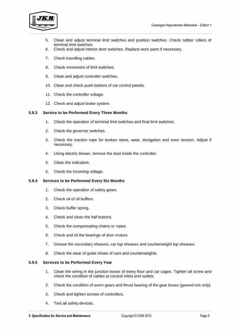
Cawangan Kejuruteraan Mekanikal – Edition 1
5. Specification for Service and Maintenance Copyright © CKM 2010 Page 5
5. Clean and adjust terminal limit switches and position switches. Check rubber rollers of terminal limit switches.
6. Check and adjust interior door switches. Replace worn parts if necessary. 7. Check travelling cables. 8. Check movement of limit switches. 9. Clean and adjust controller switches. 10. Clean and check push buttons of car control panels. 11. Check the controller voltage. 12. Check and adjust brake system.
5.9.3 Service to be Performed Every Three Months
1. Check the operation of terminal limit switches and final limit switches. 2. Check the governor switches. 3. Check the traction rope for broken wires, wear, elongation and even tension. Adjust if
necessary. 4. Using electric blower, remove the dust inside the controller. 5. Clean the indicators. 6. Check the incoming voltage.
5.9.4 Services to be Performed Every Six Months
1. Check the operation of safety gears. 2. Check oil of oil buffers. 3. Check buffer spring. 4. Check and clean the hall buttons. 5. Check the compensating chains or ropes. 6. Check and oil the bearings of door motors. 7. Grease the secondary sheaves, car top sheaves and counterweight top sheaves. 8. Check the wear of guide shoes of cars and counterweights.
5.9.5 Services to be Performed Every Year
1. Clean the wiring in the junction boxes of every floor and car cages. Tighten all screw and check the condition of cables at conduit inlets and outlets.
2. Check the condition of worm gears and thrust bearing of the gear boxes (geared m/c only). 3. Check and tighten screws of controllers. 4. Test all safety devices.

Cawangan Kejuruteraan Mekanikal – Edition 1
5. Specification for Service and Maintenance Copyright © CKM 2010 Page 6
5. Dismantle, clean and adjust the electro-magnetic brakes of gearless machines.
5.10 SCHEDULE OF RATES FOR COMPREHENSIVE SERVICE AND MAINTENANCE OF LIFT
SYSTEM
The tenderer is to note that the prices quoted for this shall not be included in the tender price and it will be binding in the event the government decides to accept it immediately after the warranty period. These prices should not be subjected to variation for the period of two (2) years after warranty period.
RATES BASED ON CONTRACT PERIOD OF TWO(2) YEARS ONLY
For the comprehensive service and maintenance
of the complete lift system and ancillary
equipment at the above premises in accordance
with the specified maintenance specifications
Charges per year
(RM)
-------------------------
Tandatangan pentender: ____________________________________
Nama dan alamat: ____________________________________ (dengan cop)
____________________________________
____________________________________
____________________________________
Tarikh: ____________________________________
Tandatangan saksi: ____________________________________
Nama dan alamat: ____________________________________
____________________________________
____________________________________
Tarikh: ____________________________________
----------------------------------------------- END OF SECTION 5 ----------------------------------------------

SECTION 6:
SCHEDULE OF DESIGN
REQUIREMENTS

SECTION 6 - SCHEDULE OF DESIGN REQUIREMENTS
TABLE OF CONTENTS
Page No.
6.1 SCOPE OF WORK 1
6.2 INSTRUCTION TO TENDERER 1
6.3 STANDARDS, RULES AND REGULATIONS 1
6.4 PROVISION FOR CONNECTION TO BUILDING SUPERVISORY SYSTEM (BSS) (WHERE APPLICABLE). 2
6.5 PERFORMANCE WITNESS TESTING 2
6.6 PRACTICAL TRAINING (WHERE APPLICABLE) 3
6.7 EQUIPMENTS FOR THE SUPERINTENDING OFFICER (S.O) 3
6.8 SUBMISSION 3
6.9 SCHEDULE OF LIFT EQUIPMENT 5
6.10 SCHEDULE OF FEATURES OF LIFTS 7
6.11 SCHEDULE OF FINISHES FOR LIFTS 9
6.12 EQUIPMENTS FOR THE S.O. 10

Cawangan Kejuruteraan Mekanikal – Edition 1
6. Schedule of Design requirements Copyright © CKM 2010 Page 1
SECTION 6 - SCHEDULE OF DESIGN REQUIREMENTS
6.1 SCOPE OF WORK
The works covered under this specification are as listed hereunder:-
i) Supplying, installing, testing and commissioning the Lift System, as specified further in this Specification, and in accordance with the details shown in the tender drawings attached to this Specifications.
ii) Supply, install, testing and commissioning split air conditioning units as specified.
iii) Guarantee, service and maintain the above mentioned system and equipment monthly for a
period of twelve (12) months from the date of handing over to JKR in good operating condition.
6.2 INSTRUCTION TO TENDERER
i) The tender shall comply with all the requirements as listed in the schedule of Design Requirements and finishes and such compliance shall not limit or restrict the offers of better equipment or finishing materials.
ii) The lifts offered shall be of the latest model available with updated microcomputer based
control systems. The lift system shall be suitable for operation within normal machine room ambient condition and shall incorporate full protection against electrical noise/interference.
Full machine calculation to justify the lift capacity, speed, travel height and rope
safety factor shall be submitted by the tenderer. Failure to do so may result in the
tender to be disqualified.
iii) Full technical literature, catalogues shall be submitted to enable a complete assessment of
the tenderer. Failure to do so shall result in the tender to be disqualified.
iv) The tenderer shall submit name and copy of certificate of the Lift Competent Person
to JKR when participating the above tender as per FACTORIES AND MACHINERY
ACT 1967 (ACT 139) & REGULATIONS AND RULES (Part III Clause 31 Page 102)
requirement.
v) The tenderer also shall submit name and copy of certificate of the Safety and Health
Officer to JKR when participating the direct contract tender.
vi) The expiry date of those certificate shall not be less than three months from the
closing date of the tender. Failure to do so may result in the tender to be
disqualified.
6.3 STANDARDS, RULES AND REGULATIONS
The above mentioned Lift system shall be constructed and installed strictly in accordance with the requirements stated in the following publications:-
(a) The most recent edition of the Factories and Machinery (Electric Passenger and Goods Lifts) Regulations, 1970, as published in the Factories and Machinery Act, 1967.
(b) The current edition of the British Standard Specifications, or the American National
Standard Specifications for Electric Lifts - BS. 5655 Pt. 1 to 10 or ANSI/ASME A 17.1 – 1981, or EN 81.
Where the requirements stated further in this Specification or in B.S. B.S. 5655 or in ANSI/ASME A 17.1 - 1981 are inconsistent, or in conflict, with the requirements stated in

Cawangan Kejuruteraan Mekanikal – Edition 1
6. Schedule of Design requirements Copyright © CKM 2010 Page 2
the Factories and Machinery (Electric Passenger and Goods Lifts) Regulations, then the Requirements stated in the Factories and Machinery (Electric Passenger and goods Lifts) Regulations shall prevail.
6.4 PROVISION FOR CONNECTION TO BUILDING SUPERVISORY SYSTEM (BSS) (WHERE
APPLICABLE).
Lift Contractor shall provide interfacing requirements, inclusive of supply and installation of Building Supervisory System (BSS) sensors, transformers and other auxiliary contacts, power contactors, BSS/manual-selector switches, as specified under Section 2 Part 29, for the proper implementation of the BSS.
6.5 PERFORMANCE WITNESS TESTING
Lift equipment shall be witness tested at the manufacturer's premises by two (2) Government
representatives to be nominated by the Pengarah Kanan Cawangan Kejuruteraan Mekanikal, Ibu
Pejabat JKR, Kuala Lumpur, before being delivered to site.
Performance rating tests shall be carried out and check against specifications and shall comply with
the approved standards.
6.5.1 Performance Witness Test on Major Equipment
Lift Contractor shall arrange with the manufacturer to inspect all major equipment and materials of high
value such as Traction machine, controller and lift car at source prior to delivery. The objective of such
inspections is to check compliance to quality standards and performance standards as stipulated in the
Contract. Performance tests witnessing shall be included in the inspection programme for approval.
Performance Witness Testing is required to ascertain that the lift component can perform its intended
design capacity and safety related function when operating under the most demanding set of limiting
conditions defined within the tender specification. The proposed testing guideline shall contain the
information which an engineer needs to establish a testing method, perform the test and evaluate the
test result. A fully comprehensive Performance Witness Test must be carried out to establish the
design compliance.
The components of testing to be carried out are:-
i) Functional test on major components
ii) Landing door locking devices
iii) Braking system
iv) Measurement of speed and current
v) Overspeed governor
vi) Alarm devices
vii) Traction and balance test
viii) Ascending car overspeed protection device.
ix) The controller Simulation test
x) Overload control
xi) Witness Test in the Testing Tower
Performance Witness Test certificates and records for tests done in the manufacturer’s factory for any
major equipment and materials shall be certified by manufacturer and witnessed by Government’s
representatives.
Lift Contractor shall include in the tender all costs that will be incurred for the Performance witness test,
including food, travelling (airfares, inland transport, airport taxes, etc.) and hotel accommodation not
lower than the current Malaysian Government rates for a period of seven (7) days for two (2) persons.

Cawangan Kejuruteraan Mekanikal – Edition 1
6. Schedule of Design requirements Copyright © CKM 2010 Page 3
6.6 PRACTICAL TRAINING (WHERE APPLICABLE)
The practical training shall be conducted for ten (10) JKR representatives to be nominated by the Pengarah Kanan Cawangan Kejuruteraan Mekanikal, Ibu Pejabat JKR.
The purpose of the training is to provide the followings:
i) Basics of traffic analysis/planning and selection of lift equipment and performance including
review of traffic design, passenger design, lift system performance, calculation of the round trip time, assumption made in derivation of the round trip time equation, other factor to be considered in the evaluation of the round trip time equation, matching passenger demand to handling capacity during up-peak traffic and passenger waiting, transit and journey times and time to destination during up-peak traffic demand.
ii) Advanced planning techniques and computer programs consist of up-peak calculation using
computer software, basic of manual calculation, flight time calculation, average distance between stops, express zones, car loading, a computer based up-peak calculation, beyond the up-peak calculation, general analysis, simulation of lift system, comparing round trip calculation and simulation, running multiple simulations, templates, comparing simulation with round trip time calculation evaluating proprietary analysis software, comparing result between different simulation programs, and much more.
A hands-on session comprising of the above topic shall be provided by Lift Contractor. Lift Contractor shall include in the tender all cost incurred for the training locally including food, travelling and hotel accommodation not inferior to the current Government practice for a period of three (3) working days, excluding travelling.
6.7 EQUIPMENTS FOR THE SUPERINTENDING OFFICER (S.O)
Lift Contractor shall supply, deliver, testing and commissioning within 14 days from the date of signing of the L.A. to Pejabat Pengarah Kanan, Cawangan Kejuruteraan Mekanikal, Ibu Pejabat JKR Malaysia, Kuala Lumpur the following equipments:
i) ii) iii) iv)
All consumables parts and items for the duration of the contract shall be provided by the Lift Contractor. Lift Contractor shall also provide maintenance or replacement of the above equipment, at all times for the duration of the contract. On settlement of the final account and defect liability of the contract, the above item shall be property of the Contractor.
6.8 SUBMISSION
6.8.1 Working Drawings
The successful tenderer shall, within thirty (30) days from the date of acceptance of tender, prepare and submit working drawings to the S.O for approval. In preparing these working drawings, the tenderer shall acquaint himself fully with the building layout and constructional details by personal examination of the architectural, structural and electrical drawings (which are available for inspections at the SO’s office) and the completed work on site so as to understand fully the requirements as regards the work to be erected and installed by him.

Cawangan Kejuruteraan Mekanikal – Edition 1
6. Schedule of Design requirements Copyright © CKM 2010 Page 4
The working drawings shall show but not limited to the following:-
i) Machine room equipment layout, ii) Machine room plan showing cut-out in slab, iii) Typical shaft plan, iv) Front elevation showing cut-outs in lift well, and v) Section through pit, shaft and machine room.
The drawing shall be fully dimensioned and show all the precise locations, arrangement and loading of the equipment. They shall also indicate location and details of all foundation, supports, chases, coreholes, opening in partitions wall, floors and roof and any other information required for works or services to be provided by others. Fully detailed and dimensioned shop drawings of lift switchboard to be supplied in this tender must also be furnished for the approval of the S.O. The drawings submitted shall be modified as necessary and, if requested by S.O., re-submitted for final approval. Six (6) sets of drawings shall than be submitted for distribution to all parties concerned.

6.9 SCHEDULE OF OF LIFT EQUIPMENT
Item Description Fireman’s Lift Other Lift
1 Location of Lift
2 Type of Lift
3 Contract Load (kg)
4 Contract Load (person)
5 Contract Speed (mps)
6 Control System
7 Operating System
8 Lift Travel Distance
9 Machine room position
10 No. of Floors Served per lift
11 No. of Entrances Served per Lift
12Clear Dimensions of Car Platform -
(W)mm x (D)mm x (H)mm
13Clear Area of Car Platform -
(W)mm x (H)mm
14 No. of Landing Doors per Lift
15 No. of Car Doors Per lift
16Car Door Type (Centre opening / Side
opening)
17Car Door Dimension -
(W)mm x (H)mm
18 No. of car operating panels per lift
19 Landing Door Type
20Landing Door Dimension -
(W)mm x (H)mm
21 Door open and close time (sec.)
Cawangan Kejuruteraan Mekanikal - Edition 1
6. Schedule of Design Requirements
________________________________________________________________________________________________________________
Copyright © CKM 2010 Page 5

Cawangan Kejuruteraan Mekanikal - Edition 1
22 No. of Hall Position Indicator and Location
23 No. of Risers of Hall Call Button
24 No. of Hall Lantern
25No and type of extractor fans in Machine
Room
26 Electrical Characteristic of Extractor Fan
27No. of Air-Conditioning Unit (In Machine
Room)
28 Capacity of Each Air-Conditioning Unit (Btu/hr)
29Central Supervisory Panel (computerised/non
computerised)
30Building Public Address system connection
and accessories in the lift car
31Message Display inside lift car (Link to PC at
the control room)
32 Door operation motor
33 CCTV requirement
● All dimensions and load shall conform to the current Factories and Machinery (Electric
Lift) Regulation.
6. Schedule of Design Requirements
________________________________________________________________________________________________________________
Copyright © CKM 2010 Page 6

Cawangan Kejuruteraan Mekanikal - Edition 1
6.10 SCHEDULE OF FEATURES OF LIFTS
No.The following shall be required and installed
as indicated:JKR REQUIREMENT
TENDERER’S
OFFER
1 Load weighing device / Load By-Pass Specified by Designer
2 Limited door reversal Control Specified by Designer
3 Door knudging control Specified by Designer
4Advance Door Opening (For High Speed Lift
Only - 2.5 m/sec and above)Required
5Automatic fan and light switch-off when idling
more than two (2) minutes.Required
6 Dual Tacho Feedback Required
7 Independent Service Specified by Designer
8 Attendant Service Control Required
9 Fire Alarm Operation Mode Required
10Emergency power operational mode with
Generator Set Power SupplySpecified by Designer
11
Light curtain device in lift car doors. A curtain
ray shall project across the car entrance and
shall operate such that the doors will return to
the open position when the ray is cut off by an
obstruction.
Required
12
Overload-Protection Device which shall
operate such that when the car becomes
overloaded the lift car shall not start and an
alarm both audio and visual on the car panel
shall be activated.
Required
13
Emergency Car Light which shall cut in and
illuminate the car during a power failure.
The emergency car light shall be powered
by a Ni-Cd battery which shall be able to
provide illumination for not less than 3 hours.
Required
14
Lift Intercom System Communication
between the master unit on ground
Floor/Control Room, each lift car and the
machine room.
Required
15 Lift supervisory board Specified by Designer
The general technical requirements and features of the lift shall also be in accordance with those
specified in this section. The tenderer shall indicate in the appropriate columns whether the lift equipment
and other equipment offered are in accordance with these requirements.
6. Schedule of Design Requirements
________________________________________________________________________________________________________________
Copyright © CKM 2010 Page 7

Cawangan Kejuruteraan Mekanikal - Edition 1
16
Battery Power Supply : A heavy duty 12V,
rechargeable Nickel-Cadium battery with
trickle charger unit shall be provided for
each lift to serve the alarm bell, lift intercom
system, emergency lighting and ventilation
fan, via a changeover contact upon failure of
normal electrical power supply.
Required
17 Fan Switch Required
18 Light Switch Required
19
A lift Attendant switch on the car operating
panel to facilitate loading and unloading of
goods.
Required
20
Attendant Operation. A two-position switch
marked to indicate "With Attendant" and
"Without Attendant". An "UP" direction button
and a "DOWN" direction button of closing the
doors and setting the direction of travel of the
lift car. A Non-Stop/Bypass switch to enable
the lift car to bypass all landing calls and
respond only to registered car calls, when
pressed continuously. A buzzer for notifying
the attendant when a car journey should be
made, to answer a landing call.
Specified By Designer
21 Leveling accuracy to be within +/- 5 mm Required
22 Fire Rating for Landing Door
i) Protected Lobbies 1 hr
ii) Unprotected Lobbies 2 hrs
23 Automatic Rescue Device/ARD.
The Lifts shall be provided with electronically
controlled automatic rescue device. The
device shall operate automatically to take the
lift car to the nearest floor and open the door
in case of power failure. The unit shall be
wired and assembled in an independent box
and shall be supplied complete with battery
charger.
Required
24
150mm wide stainless steel c/w rubber crash /
bumper rails shall be provided at suitable
heights all round the lift car. – Only for goods
lift
Specified by Designer
25Lighting, 15 Amp socket outlet and cat ladder
inside lift pitRequired
26 Energy Efficiency Features
i) High efficiency motor (MS 1525) Eff 1 / Eff 2
ii) Regenerative drive Required
ii) Energy efficient lightingLED / Compact
flourescent
6. Schedule of Design Requirements
________________________________________________________________________________________________________________
Copyright © CKM 2010 Page 8

Cawangan Kejuruteraan Mekanikal - Edition 1
6.11 SCHEDULE OF FINISHES FOR LIFTS
6.11.1 Passenger Lift
No. Descriptions For Finishes JKR REQUIREMENT TENDERER’S
OFFER
1 Operating Panels
Car operating panels Specified by Designer
Car position indicator Specified by Designer
Hall position indicator Specified by Designer
Landing operation panel Specified by Designer
2 Car And Car Door
Side enclosure Specified by Designer
Back enclosure Specified by Designer
Departmental/Client’s Logo Specified by Designer
Entrance column Specified by Designer
Front return panel Specified by Designer
Kickplate Specified by Designer
Flooring Specified by Designer
Car door Specified by Designer
Voice Synthesizer Specified by Designer
Handrail Specified by Designer
Connection to building PA System Specified by Designer
3 Hall/Landing Entrances
Landing Door Specified by Designer
Architraves (min. 300 mm width) (only at Main
Lobby)Specified by Designer
Transom Panel (if required) Specified by Designer
4 Other Features (To Specify)
Car ceiling Specified by Designer
Car push button type Specified by Designer
The general finishes for the lift shall also be in accordance with those specified in this section. The
tenderer shall indicate in the appropriate columns his offer.
The general finishes for the lift shall also be in accordance with those specified in this section. The
tenderer shall indicate in the appropriate columns his offer.
6. Schedule of Design Requirements
________________________________________________________________________________________________________________
Copyright © CKM 2010 Page 9

Cawangan Kejuruteraan Mekanikal - Edition 1
6.12 EQUIPMENTS FOR THE S.O
No. Descriptions TENDERER’S OFFER PRICE (RM)
1
2
3
4
Tandatangan pentender:
Nama dan alamat:
(dengan cop)
Tarikh:
----------------------------------------------- END OF SECTION 6 ----------------------------------------------
TOTAL PRICE (TO BE CARRIED TO SEC 8.2)
6. Schedule of Design Requirements
________________________________________________________________________________________________________________
Copyright © CKM 2010 Page 10

SECTION 7:
TECHNICAL DATA FOR
EQUIPMENT OFFERED

SECTION 7 - TECHNICAL DATA FOR EQUIPMENT OFFERED
TABLE OF CONTENTS
Page No.
7.1 SCHEDULE OF TECHNICAL DATA 1
7.2 LIST OF CATALOGUES SUPPLIED 22

SECTION 7 - TECHNICAL DATA FOR EQUIPMENT OFFERED
7.1 SCHEDULE OF TECHNICAL DATA
ITEM DESCRIPTION JKR REQUIREMENT TENDERER’S OFFER
7.1.1
(a) Name of Manufacturer: To state by Tenderer
(b) Country of Origin To state by Tenderer
(c) Type of Lift Specified by designer
(d) Model Number of Lift To state by Tenderer
(e) Number of Lifts Specified by designer
7.1.2
(a) Load Capacity (kg) Specified by designer
(b) Load Capacity (person) Specified by designer
7.1.3
(a) Contract Speed (mps) Specified by designer
(b) Total Travel of each Lift (m) Specified by designer
7.1.4
(a) Minimum headroom (O/H Travel)(m) Specified by designer
(b) Pit depth (m) Specified by designer
(c)Clear internal size of lift well required
(W)mm x (D)mmSpecified by designer
(d) Number of floors served per lift Specified by designer
Lift Performance
Lift Well, Entrances, Pit & Machine Room
The tenderer must complete this section as set out below. All information asked for must be given correctly
and supported by copies of manufacturer's published technical data for the equipment being offered.
All major components of the lift system i.e the Lift Controller, Traction Machine, Car and Safety
Devices offered shall be made by the same Original Equipment Manufacturer (OEM).
General
Lift Capacity
Cawangan Kejuruteraan Mekanikal - Edition 1
7. Technical Data of Equipment Offered
___________________________________________________________________________________________________________________
Copyright © CKM 2010 Page 1

Cawangan Kejuruteraan Mekanikal - Edition 1
(e) Number of entrances served per lift Specified by designer
(f) Position of machine room Specified by designer
7.1.5
(a) Model To state by Tenderer
(b) Name of Manufacturer To state by Tenderer
(c) Country of Origin To state by Tenderer
(d) Grouping System Specified by designer
(e) Catalogue included? Yes
7.1.6
(a) Type of Leveling Device To state by Tenderer
(b) Leveling Accuracy (mm) To state by Tenderer
7.1.7
(a) Model To state by Tenderer
(b) Name of Manufacturer To state by Tenderer
(c) Country of Origin To state by Tenderer
(d) Type of Drive System ACVVVF
(e) Premature Opening Specified by designer
(f) Technical Literature Provided Yes
7.1.8
(a) Model To state by Tenderer
(b) Name of Manufacturer To state by Tenderer
(c) Country of Origin To state by Tenderer
(d) Catalogue provided? Yes
Operation & Control System
Automatic Levelling Device
Door Operating System Control
Lift Car
7. Technical Data of Equipment Offered
___________________________________________________________________________________________________________________
Copyright © CKM 2010 Page 2

Cawangan Kejuruteraan Mekanikal - Edition 1
(e) Description of Material To state by Tenderer
(i) Roof To state by Tenderer
(ii) Ceiling To state by Tenderer
(iii) Lighting
Make To state by Tenderer
Model Number To state by Tenderer
Intensity > 50 lux
TypeLED / Compact
flourescent
(iv) Fan
Make To state by Tenderer
Model Number To state by Tenderer
Diameter To state by Tenderer
Speed To state by Tenderer
Air delivery at free air delivery of each fan
(cfm)To state by Tenderer
Power rating To state by Tenderer
Electric characteristics (volt/frequency/phase) To state by Tenderer
(v) Car front return panel Specified by designer
(vi) Car side and back enclosure covering Specified by designer
(vii) Sill To state by Tenderer
(viii) Kickplate Specified by designer
(ix) Car Platform/Flooring Specified by designer
(x) Clear internal size of car platform Specified by designer
(xi) Clear internal area of car platform Specified by designer
7. Technical Data of Equipment Offered
___________________________________________________________________________________________________________________
Copyright © CKM 2010 Page 3

Cawangan Kejuruteraan Mekanikal - Edition 1
(xii) Clear internal height Specified by designer
7.1.9
(a) Testing Method To state by Tenderer
(b) Testing equipment To state by Tenderer
(c) Inside the lift car [dB(A)] < 58 2
(d) Lift lobby [dB(A)] < 58 ± 2
(e) Inside the lift motor room [dB(A)] < 75 ± 2
(f) Inside lift shaft [dB(A)] < 70 ± 2
7.1.10
(a) Testing Method To state by Tenderer
(b) Testing equipment To state by Tenderer
(c) Acceleration rate (m/s²) < 1.2
(d) Deceleration rate (m/s²) < 1.2
(e) Sustained Jerk rate (m/s3) < 1.4
(f) Vibration [milli(g)) on average] < 12
7.1.11
(a) Model To state by Tenderer
(b) Name of Manufacturer To state by Tenderer
(c) Country of Origin To state by Tenderer
(d) Catalogue or type no To state by Tenderer
(e) Material of panel Specified by designer
(f) Type of Indication To state by Tenderer
Sound Level
Vibration
Car Position Indicator
7. Technical Data of Equipment Offered
___________________________________________________________________________________________________________________
Copyright © CKM 2010 Page 4

Cawangan Kejuruteraan Mekanikal - Edition 1
7.1.12
(a) Type no (based on catalogue) To state by Tenderer
(b) Material of panel Specified by designer
(c) No. of operating panels per car Specified by designer
(d) Highest button of COP from car floor (mm) Specified by designer
7.1.13
(a) Brand To state by Tenderer
(b) Name of Manufacturer To state by Tenderer
(c) Country of Origin To state by Tenderer
(d) Type no (based on catalogue) To state by Tenderer
(e) Material of panel Specified by designer
(f) Type of Button Specified by designer
7.1.14
(a) Type no (based on catalogue) To state by Tenderer
(b) Material of panel To state by Tenderer
(c) Type of Indication Specified by designer
7.1.15
(a) Model To state by Tenderer
(b) Name of Manufacturer To state by Tenderer
(c) Country of Origin To state by Tenderer
(d) Type no (based on catalogue) To state by Tenderer
(e) Material of panel To state by Tenderer
(f) Type of Indication Specified by designer
Hall Position Indicator
Car Operating Panel
Hall Call Button
Hall Lantern
7. Technical Data of Equipment Offered
___________________________________________________________________________________________________________________
Copyright © CKM 2010 Page 5

Cawangan Kejuruteraan Mekanikal - Edition 1
7.1.16
(a) Material and construction of car door Specified by designer
(b) Type of door Specified by designer
(c) Clear door opening width and height Specified by designer
(d) Type of car door motor ACVVVF
(e) Country of manufacture To state by Tenderer
(f) Door steel plate thickness Minimum 1.2 mm
(g) Type of door sensorPhotocell and safety
edge
7.1.17
(a) Material and construction of landing door Specified by designer
(b) Type of door Specified by designer
(c) Clear door opening width and height (mm) Specified by designer
(d) Country of manufacture To state by Tenderer
(e)
- Protected lobby 1 hour
- Unprotected lobby 1 hour
7.1.18
(a) Model No. To state by Tenderer
(b) Name of Manufacturer To state by Tenderer
(c) Country of Origin To state by Tenderer
(d) Type of motor AC / DC
(e) Type of traction Specified by designer
(f)Type of mounting of machine and type of
vibration damperTo state by Tenderer
Car Door
Landing Doors
Traction Motor
Landing door fire rating (SIRIM or equivalent certificate to be enclosed)
7. Technical Data of Equipment Offered
___________________________________________________________________________________________________________________
Copyright © CKM 2010 Page 6

Cawangan Kejuruteraan Mekanikal - Edition 1
(g) R.P.M. (For Geared Machine Only) To state by Tenderer
(h) Diameter of sheave To state by Tenderer
(i) Material of sheave To state by Tenderer
(j) Type of brakeSpring operated,
double stroke type
(k) Material of brake To state by Tenderer
(l) Electric characteristics (volt/frequency/phase) Specified by designer
(m) Motor Power (kW) To state by Tenderer
(n) Power Factor To state by Tenderer
(o) Machine calculation To be enclosed
(p) Certificate Yes
(q) Catalogue included Yes
(r) Type of cooling Specified by designer
(s)
- Name of Manufacturer To state by Tenderer
- Model No. To state by Tenderer
- Flow (CFM) To state by Tenderer
- Motor Insulation Class To state by Tenderer
(t) Motor Efficiency (complied to MS1525) Eff 1 / Eff 2
7.1.19
(a) Number of ropes per car > 3 nos each car
(b) Diameter of ropes > 10mm
(c) Construction and material To state by Tenderer
Traction Rope
Machine calculations shall be submitted with this tender document. All of the above calculations shall be
endorsed by Lift Competent Person. Failure to do so may result in the tender to be disqualified.
If motor is fan cooled, please specified fan data as below
7. Technical Data of Equipment Offered
___________________________________________________________________________________________________________________
Copyright © CKM 2010 Page 7

Cawangan Kejuruteraan Mekanikal - Edition 1
(d) Method of terminatingBulldog grip / Swaged
/ Socket end
(e) Name of Manufacturer To state by Tenderer
(f) Certificate Of Approval (relevant authority) Yes
7.1.20
(a) Model To state by Tenderer
(b) Name of Manufacturer To state by Tenderer
(c) Country of Origin To state by Tenderer
(d) Type Specified by designer
(e) Means of actuating safety gear Specified by designer
(f) Certificate Yes
(g) Catalogue included Yes
7.1.21
(a) Model To state by Tenderer
(b) Name of Manufacturer To state by Tenderer
(c) Country of Origin To state by Tenderer
(d) Type To state by Tenderer
(e) Tripping speed To state by Tenderer
(f) Diameter of governor rope > 3mm
(g) Certificate Yes
(h) Catalogue included Yes
7.1.22
(a) Provided Yes
Speed Governor
Compensation
Safety Gear
COA shall be submitted with this tender document. Failure to do so may result in the tender to be
disqualified.
7. Technical Data of Equipment Offered
___________________________________________________________________________________________________________________
Copyright © CKM 2010 Page 8

Cawangan Kejuruteraan Mekanikal - Edition 1
(b) Type chain/ropeInterwoven with sash
cord
7.1.23
(a) Manufacturer To state by Tenderer
(b) Material Solid steel
(c) Type Solid ‘T’ section
(d) Section dimension of car guide (mm) To state by Tenderer
(e) Type of joint Tongue & groove
(f) Type of fastening Bolt & nut
(g) Guide rail size (kg/m) > 8
(h) Spacing of bracket (mm) To state by Tenderer
(i) Certificate Yes
7.1.24
(a) Material To state by Tenderer
(b) Type Specified by designer
(c) Make To state by Tenderer
7.1.25
(a) Model To state by Tenderer
(b) Name of Manufacturer To state by Tenderer
(c) Country of Origin To state by Tenderer
(d) Type Specified by designer
(e) Stroke (mm) To state by Tenderer
(f) Max. retardation rate (m/s²) To state by Tenderer
(g) No. of car buffer per lift Specified by designer
Car Lift’s Guide Rails
Car’s Guide Shoe
Car Buffers
7. Technical Data of Equipment Offered
___________________________________________________________________________________________________________________
Copyright © CKM 2010 Page 9

Cawangan Kejuruteraan Mekanikal - Edition 1
7.1.26
(a) Material Cast iron
(b) Make To state by Tenderer
(c) Weight per piece (kg) To state by Tenderer
(d) Certificate Yes
7.1.27
(a) Manufacturer To state by Tenderer
(b) Material Solid steel
(c) Type Solid ‘T’ section
(d)Section dimension of counter weight guide
(mm)To state by Tenderer
(e) Type of joint Tongue & groove
(f) Type of fastening Bolt & nut
(g) Guide rail size (kg/m) > 8
(h) Spacing of bracket (mm) To state by Tenderer
(i) Certificate Yes
7.1.28
(a) Material To state by Tenderer
(b) Type Specified by designer
(c) Make To state by Tenderer
7.1.29
(a) Model To state by Tenderer
(b) Name of Manufacturer To state by Tenderer
(c) Country of Origin To state by Tenderer
Counterweight Buffers
Counterweight’s Guide Rails
Counterweight Guide Shoe
Counterweight
7. Technical Data of Equipment Offered
___________________________________________________________________________________________________________________
Copyright © CKM 2010 Page 10

Cawangan Kejuruteraan Mekanikal - Edition 1
(d) Type Specified by designer
(e) Max. retardation rate (m/s²) To state by Tenderer
(f) No. of counter weight buffer per lift Specified by designer
7.1.30
(a) Section dim. of door frame (mm) To state by Tenderer
(b) BSW gauge of door frame To state by Tenderer
7.1.31
(a) Number of lifts with fireman's service Specified by designer
7.1.32
(a) Lift starting current full load up To state by Tenderer
(b) Incoming power rating required To state by Tenderer
(c) Lift power rating required To state by Tenderer
(d) Lift Switchboard
Manufacturer To state by Tenderer
Fuse switch (for motor) – 3phase To state by Tenderer
Switch Fuse (for car lighting, fan – 3 phase) To state by Tenderer
Voltmeter To state by Tenderer
Ammeter To state by Tenderer
Indicating Light To state by Tenderer
HRC fuses To state by Tenderer
Cables PVC (non armoured) To state by Tenderer
7.1.33
(a) Manufacturer To state by Tenderer
Architraves [Refer to Tender Drawing & Section 6.10 (Schedule of Finishes)]
Fireman's Service
Electrical Installation Work
Battery For Emergency Lighting And Fan
7. Technical Data of Equipment Offered
___________________________________________________________________________________________________________________
Copyright © CKM 2010 Page 11

Cawangan Kejuruteraan Mekanikal - Edition 1
(b) Model To state by Tenderer
(c) Battery type Nickel Cadmium
(d) Voltage and no. of plates To state by Tenderer
(e) Battery Rating To state by Tenderer
Battery Charger
(a) Manufacturer To state by Tenderer
(b) Model name and type To state by Tenderer
(c) Certificate Yes
7.1.34
(a) Is emergency power operation as specified? To state by Tenderer
(b) Give details To state by Tenderer
7.1.35
(a) Give details To state by Tenderer
Emergency Power Operation
Load Weighing Device
7. Technical Data of Equipment Offered
___________________________________________________________________________________________________________________
Copyright © CKM 2010 Page 12

Cawangan Kejuruteraan Mekanikal - Edition 1
7.1.36
(a) Give details To state by Tenderer
7.1.37
(a) Give details To state by Tenderer
7.1.38 Advance Door Opening (For High Speed Lift Only)
(a) Give details To state by Tenderer
7.1.39 Nuisance Car Call Protection
(a) Give details To state by Tenderer
Limited Door Reversible
Load By-Pass
7. Technical Data of Equipment Offered
___________________________________________________________________________________________________________________
Copyright © CKM 2010 Page 13

Cawangan Kejuruteraan Mekanikal - Edition 1
7.1.40 Automatic Light And Fan Cut-Off
(a) Give details To state by Tenderer
7.1.41 Independent Service
(a) Give details To state by Tenderer
7.1.42 Fire Alarm Operational Mode
(a) Give details To state by Tenderer
7.1.43 Lift Intercom System
(a) Give details To state by Tenderer
7. Technical Data of Equipment Offered
___________________________________________________________________________________________________________________
Copyright © CKM 2010 Page 14

Cawangan Kejuruteraan Mekanikal - Edition 1
7.1.44 Priority Call At All Landing With Access Card For VIP Lift (Where applicable)
(a) Give details To state by Tenderer
7.1.45 Automatic Rescue Device
(a) Model To state by Tenderer
(b) Name of Manufacturer To state by Tenderer
(c) Country of Origin To state by Tenderer
(d) Operation details To state by Tenderer
(e) Certificate Yes
Battery
(a) Manufacturer To state by Tenderer
(b) Model name To state by Tenderer
(c) Type Nickel cadmium
(d) Voltage and no. of plates To state by Tenderer
(e) Battery Rating To state by Tenderer
(f) Certificate Yes
Battery Charger
(a) Manufacturer To state by Tenderer
(b) Model name and type To state by Tenderer
(c) Certificate Yes
7. Technical Data of Equipment Offered
___________________________________________________________________________________________________________________
Copyright © CKM 2010 Page 15

Cawangan Kejuruteraan Mekanikal - Edition 1
7.1.46 Extract Fans For Lift Machine Rooms
(a) Total No. of Extract fans Specified by designer
(b) Make and Model Number To state by Tenderer
(c) Dimension To state by Tenderer
(d) Speed To state by Tenderer
(e)Air delivery at free air delivery of each fan
(cfm)Specified by designer
(f) Power rating To state by Tenderer
(g) Electric characteristics (volt/frequency/phase) Specified by designer
(h)All fans (new & existing) with heavy duty
thermostat controlYes
(i) Duct (material and gauge) To state by Tenderer
Exhaust Air Grille
(a) Make To state by Tenderer
(b) Material To state by Tenderer
(c) Thickness To state by Tenderer
7.1.47 Air-Conditioning Unit
Indoor Units
(a) Type Specified by designer
(b) Make To state by Tenderer
(c) Model To state by Tenderer
(d) Type of refrigerant used To state by Tenderer
(e)Total cooling capacity rating, kW @ 50°C CT
with designed entering air conditionsSpecified by designer
(f) Air Flow Rate (cfm) To state by Tenderer
(g) Evaporator fan motor kW To state by Tenderer
7. Technical Data of Equipment Offered
___________________________________________________________________________________________________________________
Copyright © CKM 2010 Page 16

Cawangan Kejuruteraan Mekanikal - Edition 1
(h) Dimension (WxHxD) To state by Tenderer
(i) Weight (kg) To state by Tenderer
Outdoor Units
(a) Make & Model of compressors To state by Tenderer
(b) Compressor rpm To state by Tenderer
(c) No. of compressors/kW To state by Tenderer
(d) Power Supply (volt/frequency/phase) Specified by designer
(e) Material of condenser fin To state by Tenderer
(f) Material of bolts & nuts To state by Tenderer
(g) Max. Starting Current (Amps.) To state by Tenderer
(h) Running Current (Amps.) To state by Tenderer
(i) Total Power Consumption (kW) To state by Tenderer
(j) Condenser Air Quantity (cfm) To state by Tenderer
(k) Dimension (WxHxD) To state by Tenderer
(l) Weight (kg) To state by Tenderer
(m) Temperature Control To state by Tenderer
(n) Safety Devices (Overload/etc.) To state by Tenderer
(o)Is condenser unit able to withstand marine
environment? Specified by designer
(p) Automatic changeover 12 hours Specified by designer
7.1.48 Voice Synthesizer
(a) Brand To state by Tenderer
(b) Make To state by Tenderer
(c) Model To state by Tenderer
(d) Voice storage & Processing To state by Tenderer
7. Technical Data of Equipment Offered
___________________________________________________________________________________________________________________
Copyright © CKM 2010 Page 17

Cawangan Kejuruteraan Mekanikal - Edition 1
(e) In-Car Speaker To state by Tenderer
(f) Operation details To state by Tenderer
(g) Language Specified by designer
7.1.49 Anti-Vandalism Features For Buttons
(a) Type Specified by designer
(b) Material Specified by designer
(c) Location Specified by designer
7.1.50 Connection To Building Public Address System
(a) Brand To state by Tenderer
(b) Diameter of Speaker To state by Tenderer
(c) Resistance of Speaker To state by Tenderer
(d) Speaker Power (Watt) To state by Tenderer
(e) Type of Cable Specified by designer
7.1.51 Lift Competent Person
(a) Name of Person To state by Tenderer
(b) JKKP Registration No. To state by Tenderer
(c) Certificate Validity To state by Tenderer
7.1.52 Safety Officer
(a) Name of Person To state by Tenderer
(b) DOSH/NIOSH Certificate No. To state by Tenderer
(c) Certificate Validity To state by Tenderer
7. Technical Data of Equipment Offered
___________________________________________________________________________________________________________________
Copyright © CKM 2010 Page 18

Cawangan Kejuruteraan Mekanikal - Edition 1
7.1.53 Central Supervisory Panel
(a) Brand and Model To state by Tenderer
(b) Type To state by Tenderer
(c) Location Specified by designer
(d) Type and brand of monitor To state by Tenderer
(e) Type and brand of CPU To state by Tenderer
(f) Type and brand of printer To state by Tenderer
7.1.54 Lightning and Surge Protector (Three Phase Power Line)
(a) Make To state by Tenderer
(b) Brand and Model No. To state by Tenderer
(c) Nominal Voltage 415V
(d) Working Voltage To state by Tenderer
(e) Maximum Surge Current To state by Tenderer
(f) Current Rating To state by Tenderer
(g) Leakage Current To state by Tenderer
(h) Temperature Range To state by Tenderer
(i) Enclosure Material To state by Tenderer
(j) Dimension To state by Tenderer
(k) Catalogue included Yes
7. Technical Data of Equipment Offered
___________________________________________________________________________________________________________________
Copyright © CKM 2010 Page 19

Cawangan Kejuruteraan Mekanikal - Edition 1
7.1.55 Lightning and Surge Protector (Single Phase Power Line)
(a) Make To state by Tenderer
(b) Brand and Model No. To state by Tenderer
(c) Nominal Voltage 240V
(d) Working Voltage To state by Tenderer
(e) Maximum Surge Current To state by Tenderer
(f) Current Rating To state by Tenderer
(g) Leakage Current To state by Tenderer
(h) Temperature Range To state by Tenderer
(i) Enclosure Material To state by Tenderer
(j) Dimension To state by Tenderer
(k) Catalogue included Yes
7.1.56 Lightning and Surge Protector (Signal Line)
(a) Make To state by Tenderer
(b) Brand and Model No. To state by Tenderer
(c) Nominal Voltage To state by Tenderer
(d) Working Voltage To state by Tenderer
(e) Maximum Surge Current To state by Tenderer
(f) In-line Resistance To state by Tenderer
(g) Temperature Range To state by Tenderer
(h) Enclosure Material To state by Tenderer
(i) Dimension To state by Tenderer
(j) Catalogue included To state by Tenderer
7. Technical Data of Equipment Offered
___________________________________________________________________________________________________________________
Copyright © CKM 2010 Page 20

Cawangan Kejuruteraan Mekanikal - Edition 1
7.1.57 Regenerative Drives
(a) Give details To state by Tenderer
Tandatangan pentender:
Nama dan alamat:
(dengan cop)
Tarikh:
Tandatangan saksi::
Nama dan alamat:
(dengan cop)
Tarikh:
7. Technical Data of Equipment Offered
___________________________________________________________________________________________________________________
Copyright © CKM 2010 Page 21
Cawangan Kejuruteraan Mekanikal - Edition 1
7.2 LIST OF CATALOGUES SUPPLIED
No.
(a)
(b)
(c)
(d)
(e)
(f)
(g)
(h)
(i)
(j)
(k)
Tandatangan pentender:
Nama dan alamat:
(dengan cop)
Tarikh:
Tandatangan saksi::
Nama dan alamat:
(dengan cop)
Tarikh:
Description
----------------------------------------------- END OF SECTION 7 ----------------------------------------------
7. Technical Data of Equipment Offered
___________________________________________________________________________________________________________________
Copyright © CKM 2010 Page 22

SECTION 8:
SCHEDULE OF PRICES

SECTION 8 - SCHEDULE OF PRICES
TABLE OF CONTENTS
Page No.
8.1 LIFT 1
8.2 PRELIMINARIES 2
8.3 SUMMARY OF PRICE 3
8.4 SCHEDULE OF DELIVERY, INSTALLATION AND COMMISSIONING 4

SECTION 8 - SCHEDULE OF PRICES
8.1
NO DESCRIPTION OF WORK PRICE (RM)
1 Lift Car(s) inclusive of all Panels and Attachments
2 Landing Doors including Frames, Sills
3 Hall Lantern(s), Position Indicators, Call Buttons
4 Traction Machine(s) c/w Sheaves, Regenerative Drives
5 Governors and Ropes
6 Controllers and shaft information
7 Traveling cables and its accessories
8 Electrical Switchboards
9 Cables and Wiring
10 Intercom System
11 Central Supervisory Panel
12 Batteries with Trickle Chargers
13 Car Buffers
14 Counterweight Buffers
15 Counterweights
16 Guide rails and attachments
17 Traction Ropes
18 Automatic Rescue Device
19 Public Address (PA) System
20 Lightning and Surge Protectors
21 Cat Ladder Inside Lift Pit
22 Installation (According to the Installation Schedule)
23Dismantling, removing and carting away of old equipment and ancillaries
from site. (for replacement work)**
24 Air-Conditioning Systems
25 Exhaust Fans c/w accessories
26 Testing and commissioning including vibration test and noise test
27Comprehensive service and maintenance of lifts for 12 months after
handing over.
The prices entered in this schedule shall be for the supply, installation, testing and commissioning, inclusive
of all costs, labour charges, installation costs, overheads etc. of the complete lift system and all ancillary
equipment in accordance with the requirements of the specifications and the tender drawings.
(Contractor shall fill in the items below individually and not as inclusive)
SUB-TOTAL TO CARRIED BE TO SUMMARY OF PRICES
LIFT
Cawangan Kejuruteraan Mekanikal - Edition 1
8. Schedule of Prices
___________________________________________________________________________________________________________________
Copyright © CKM 2010 Page 1

Cawangan Kejuruteraan Mekanikal - Edition 1
8.2
NO DESCRIPTION OF WORK PRICE (RM)
1 Performance Bond ( Bon Perlaksanaan)
2 Insurances
3 Preparation of 12 copies of Contract Documents.
4 (Hardcover Binding)
5
CIDB levy (this shall include payment for levy to the Lembaga
Pembangunan Industri Pembinaan Malaysia under part VIII of the LPIP
Act 1994 and the Construction Industry (Levy Collection Regulation
1996))
6 Supply equipment for the S.O as specified in section 6.7
7Shop Drawings, As built Drawing, Maintenance and Operations Manuals
and other manuals necessary for the installation.
8 Testing Fees by respective authority inclusive of submission fees.
9 One year maintenance (12 months) during warranty period.
10 Signage and notices
11 Operating Instruction And Repair Manual
12 Performance Witness Testing (as per section 6.5)
13 Practical Training (as per section 6.6)
14 Safety and Health Officer (for direct contract only)
15 Management Cost (Inclusive of attending site and technical meeting)
a) Accommodation
b) Transportation
c) Miscellaneous
16Other necessary work not included above but necessary to complete the
installation of the system. (Please Specify):-
a)
b)
c)
PRELIMINARIES
SUB-TOTAL TO CARRIED BE TO SUMMARY OF PRICES
8. Schedule of Prices
___________________________________________________________________________________________________________________
Copyright © CKM 2010 Page 2

Cawangan Kejuruteraan Mekanikal - Edition 1
8.3
NO DESCRIPTION OF WORK PRICE (RM)
8.1 LIFT
8.2 PRELIMINARIES
Tandatangan pentender:
Nama dan alamat:
(dengan cop)
Tarikh:
Tandatangan saksi::
Nama dan alamat:
(dengan cop)
Tarikh:
TOTAL PRICE TO BE CARRIED FORWARD TO FORM OF TENDER
SUMMARY OF PRICE
8. Schedule of Prices
___________________________________________________________________________________________________________________
Copyright © CKM 2010 Page 3

Cawangan Kejuruteraan Mekanikal - Edition 1
8.4
No. Description Duration (weeks)
a) Ordering, fabrication and shipping of equipment: (from award of tender)
b) Dismantling of existing equipment: (Only for replacement work)
c) Installation of new equipment c/w all wiring works:
d) Cladding and finishes works:
e) Testing and commissioning:
f) JKKP Inspection:
Tandatangan pentender:
Nama dan alamat:
(dengan cop)
Tarikh:
Tandatangan saksi::
Nama dan alamat:
(dengan cop)
Tarikh:
SCHEDULE OF DELIVERY, INSTALLATION AND COMMISSIONING
The tenderer must submit the following information, ascertaining his capability to complete the works by the
stipulated date.
TOTAL
----------------------------------------------- END OF SECTION 8 ----------------------------------------------
8. Schedule of Prices
___________________________________________________________________________________________________________________
Copyright © CKM 2010 Page 4

SECTION 9:
SCHEDULE OF RATES
SECTION 9 - SCHEDULE OF RATES
TABLE OF CONTENTS
Page No.
9.1 MACHINE ROOM 1
9.2 HOISTWAY 1
9.3 CAR CAGE 2
9.4 ENTRANCE 3

SECTION 9 - SCHEDULE OF RATES
ITEM DESCRIPTIONSIZE
(Specified by designer)
9.1
(a) Traction machine __________ kw per pcs
(b) Machine base - per pcs
(c) Machine beam
i) I-Beam - per m
(d) Sheave guard - per pcs
(e) Controller __________ m/s per pcs
(f) Inverter / drive unit __________ kw per pcs
(g) Governor __________ m/s per pcs
9.2
(a) Guide rail & bracket __________ Kg/m per m
(b) Hoist rope
i) 10mm per m
ii) 12mm per m
iii) 13mm per m
iv) 14mm per m
v) 16mm per m
The following rates for the various items of the work shall be used in the event of any variation, addition or
deduction in the quantities installed.
The rates shall include costs of supply, installation, incidentals, accessories, overheads and profit. Such
rates are subjected to the agreement of the Pengarah Kanan Cawangan Kejuruteraan Mekanikal as to their
reasonableness.
General description of work and materials shall be as stated in the appropriate section of the Conditions of
Contract and the Specification.
All major components of the lift system i.e the Lift Controller, Traction Machine, Car and Safety
Devices offered shall be made by the same Original Equipment Manufacturer (OEM).
Machine Room
Hoistway
RATE (RM)
Diameter
Cawangan Kejuruteraan Mekanikal - Edition 1
9. Schedule Of Rates
___________________________________________________________________________________________________________________
Copyright © CKM 2010 Page 1

Cawangan Kejuruteraan Mekanikal - Edition 1
(c) Governor rope
i) 6 mm per m
ii) 8 mm per m
(d) Hoistway wiring - per m
(e) Travelling cable - per m
(f) Limit switch & bracket - per pcs
(g) Levelling vane & bracket - per pcs
(h) Counterweight - per kg
(i)Counterweight guide shoe
(base on lift speed)__________ m/s per pcs
(j) Counterweight guard m per m
(k) Filler weight Kg per pcs
(l) Buffer
i) Spring BufferStroke = _______ m
Speed = ______ m/sper pcs
ii) Oil BufferStroke = _______ m
Speed = ______ m/sper pcs
(m) Tailweight - per pcs
(n) Pit stop switch One lift each per pcs
(o) Compensation chain kg/m per m
(p) Facial plate - per m2
9.3
(a) Cabin Depth X Width per m2
(b)Car guide shoe (base on lift
speed)per pcs
(c) Door operator __________ kw per pcs
(d) Car doors
i) Side opening
Car cage
Diameter
9. Schedule Of Rates
___________________________________________________________________________________________________________________
Copyright © CKM 2010 Page 2

Cawangan Kejuruteraan Mekanikal - Edition 1
- Etched stainless steel - per m2
- Hairline stainless steel - per m2
ii) Centre opening
- Etched stainless steel - per m2
- Hairline stainless steel - per m2
(e) Suspended ceiling m per m
(f) Lighting
i) Fluorescent __________ kw per pcs
ii) Down light __________ kw per pcs
ii) LED light __________ kw per pcs
(g) Cross flow fan __________ cfm per unit
(h) COP with buttons - per set
(i) Call buttons - per pcs
(j) Car buttons - per pcs
(k) Position indicator - per pcs
(l) Safety edge / photo curtain - per pcs
(m) Car sill - per pcs
(n) Safety gear - per pcs
9.4
(a) Landing door - per m2
(b) Door jamb
i) wide
- Etched stainless steel - per m2
- Hairline stainless steel - per m2
ii) narrow
- Etched stainless steel - per m2
Entrance
9. Schedule Of Rates
___________________________________________________________________________________________________________________
Copyright © CKM 2010 Page 3

Cawangan Kejuruteraan Mekanikal - Edition 1
- Hairline stainless steel - per m2
(c) Hall station with buttons - per set
(d) Firemen’s switch - per set
(e) Firemen’s switch glass - per pcs
(f) Position indicator - per set
(g) Lantern - per set
(h) Landing sill - per pcs
Tandatangan pentender:
Nama dan alamat:
(dengan cop)
Tarikh:
Tandatangan saksi::
Nama dan alamat:
(dengan cop)
Tarikh:
----------------------------------------------- END OF SECTION 9 ----------------------------------------------
9. Schedule Of Rates
___________________________________________________________________________________________________________________
Copyright © CKM 2010 Page 4

SECTION 10:
OTHER REQUIREMENTS (N/A)

SECTION 11:
LIST OF DRAWINGS