SINUMERIK & SINAMICS Equipment for Machine...
372
SINUMERIK & SINAMICS Equipment for Machine Tools Catalog News NC 61 N • August 2012 Motion Control Answers for industry. © Siemens AG 2012
Transcript of SINUMERIK & SINAMICS Equipment for Machine...

SINUMERIK & SINAMICS Equipment for Machine ToolsCatalog News NC 61 N • August 2012
Motion Control
Answers for industry.
© Siemens AG 2012

SINUMERIK & SINAMICS NC 61Equipment for Machine Tools
E86060-K4461-A101-A3-7600
SINUMERIK 840D sl Type 1B NC 62Equipment for Machine Tools
E86060-K4462-A101-A1-7600
SIMATIC ST 70Products forTotally Integrated Automation and Micro Automation
E86060-K4670-A101-B3-7600
SIMATIC HMI / ST 80/ST PCPC-based AutomationHuman Machine Interface SystemsPC-based Automation
E86060-K4680-A101-B8-7600
Industrial Communication IK PISIMATIC NET
E86060-K6710-A101-B7-7600
SITOP KT 10.1Power supplySITOP
E86060-K2410-A111-A8-7600
SITRAIN ITCTraining for Automation and Industrial Solutions
Only available in GermanE86060-K6850-A101-C3
Products for Automation CA 01and DrivesInteractive Catalog
DVD: E86060-D4001-A510-D2-7600
Industry MallInformation and Ordering Platformin the Internet:
www.siemens.com/industrymall
Hardware and software requirements:• Intel Pentium 1 GHz or higher• Minimum 512 MB of RAM• Screen resolution 1024 x 768 pixels• CD-ROM drive, at least 16x • Windows XP/Vista• Acrobat Reader 7.0 or higher• MS Internet Explorer V6.0 (SP2) or higherStartInsert the CD-ROM into the CD-ROM drive. The program starts automatically. If the AutoRun function is not activated in your system, start filestart.hta from the CD-ROM using the Windows Explorer.
NoteInstallation is not necessary to view the information on this CD-ROM. This does not apply, however, when using dimensional drawings in DXF format.
HotlinePlease send any questions or suggestions to: [email protected]
In the CD-ROM that accompanies Catalog News NC 61 N · August 2012, you will find:• Information about planning/configuring based on
the technical documentation; additional technical documentation can be found at:www.siemens.com/automation/doconweb
• Dimensional drawings of our motors in PDF/DXF format or via CAD CREATORwww.siemens.com/cadcreator
• Glossary for the explanation of terms and functions
• Catalog NC 61 · 2010 in electronic form (PDF format)
• Catalog News NC 61 N · August 2012 in electronic form (PDF format)
Motion Control
SINUMERIK & SINAMICS
Ausrüstungen für Werkzeugmaschinen
Katalog News NC 61 N · August 2012
© S
iem
ens
AG 2
012
| Än
deru
nge
n v
orb
ehal
ten
| P
rin
ted
in G
erm
any
08/2
012
Related catalogs CD-ROM for Catalog News NC 61 N · August 2012
© Siemens AG 2012

Motion ControlSINUMERIK & SINAMICSEquipment for Machine Tools
Catalog News NC 61 N · August 2012
Supersedes:Catalog NC 61 · 2010 chapters 2 and 10
Refer to the Industry Mall for current updates of this catalog: www.siemens.com/industrymall
The products contained in this catalog can also be found in the electronic catalog CA 01.Order No.:E86060-D4001-A510-D2-7600
Please contact your local Siemens branch
© Siemens AG 2012
The products and sys-tems described in this catalog are distributed under application of a certified quality and environmental manage-ment system in accor-dance with DIN EN ISO 9001 (Certified Registra-tion No. 001258 QM08) and DIN EN ISO 14001 (Certified Registration No. 001258 UM). The certificates are recog-nized by all IQNet countries.
Introduction 1
Overview of functionsExport information · CNC controls 2
Operator components for CNC controlsOperator panels 3
HMI software for CNC controlsTools 4
Basic components 5
SINAMICS S120 drive system 6
Synchronous motorsSIMOTICS M-1PH8/S-1FT7/S-1FK7 motorsSIMOTICS T-1FW6 motorsGearboxes
7
Asynchronous motorsSIMOTICS M-1PH8 motors 8
Measuring systems Absolute encoders 9
Connection system MOTION-CONNECTPower cables · Signal cablesDRIVE-CLiQ cables · Length code
10
Services and supplementary productsManufacturing ExcellenceSINUMERIK Solution PartnersTraining
11
AppendixIndexes Conditions of sale and deliveryExport regulations
12
Printed on paper from sustainably managed forests and controlled sources.
www.pefc.org
© Siemens AG 2012

2 Siemens NC 61 N · August 2012
© Siemens AG 2012

3Siemens NC 61 N · August 2012
Answers for industry.
Siemens Industry answers the challenges in the
manufacturing and the process industry as well as in
the building automation business. Our drive and automation
solutions based on Totally Integrated Automation (TIA) and
Totally Integrated Power (TIP) are employed in all kinds
of industry. In the manufacturing and the process industry.
In industrial as well as in functional buildings.
Siemens offers automation, drive, and low-voltage switching technology as well as industrial software from stan-dard products up to entire industry solu-tions. The industry software enables our industry customers to optimize the en-tire value chain – from product design and development through manufacture and sales up to after-sales service. Our electrical and mechanical components offer integrated technologies for the en-tire drive train – from couplings to gear units, from motors to control and drive solutions for all engineering industries. Our technology platform TIP offers robust solutions for power distribution.
The high quality of our products sets industry-wide benchmarks. High environmental aims are part of our eco-management, and we imple-ment these aims consistently. Right from product design, possible effects on the environment are examined. Hence many of our products and systems are RoHS compliant (Restriction of Hazard-ous Substances). As a matter of course, our production sites are certified ac-cording to DIN EN ISO 14001, but to us, environmental protection also means most efficient utilization of valuable resources. The best example are our energy-efficient drives with energy savings up to 60 %.
Check out the opportunities our automation and drive solutions provide. And discover how you can sustainably enhance your competitive edge with us.
© Siemens AG 2012

4 Siemens NC 61 N · August 2012
Setting standards in productivity and competitiveness.Totally Integrated Automation.
© Siemens AG 2012

5Siemens NC 61 N · August 2012
Thanks to Totally Integrated Automation, Siemens provides
an integrated basis for the implementation of customized
automation solutions – in all industries from inbound to
outbound.
TIA is characterized by its unique continuity.
It provides maximum transparency at all levels with reduced interfacing requirements – covering the field level, production control level, up to the corporate management level. With TIA you also profit throughout the complete life cycle of your plant – starting with the initial planning steps through operation up to modernization, where we offer a high measure of investment security re-sulting from continuity in the further development of our products and from reducing the number of interfaces to a minimum.
The unique continuity is already a defined characteristic at the development stage of our products and systems.
The result: maximum interoperability – covering the controller, HMI, drives, up to the process control system. This reduces the complexity of the automation solution in your plant. You will experience this, for example, in the engineering phase of the automation solution in the form of reduced time requirements and cost, or during operation using the continuous diagnostics facili-ties of Totally Integrated Automation for increasing the availability of your plant.
© Siemens AG 2012

6 Siemens NC 61 N · August 2012
© Siemens AG 2012

Siemens NC 61 N · August 2012
22/2 SINUMERIK CNCs2/2 Export control information
Standard/export versions
2/4 Control structure and configuration2/14 Drives2/24 Drive functions2/28 Axis functions2/28 Spindle functions2/30 Interpolations2/32 Couplings2/34 Transformations2/34 Measuring functions/measuring cycles2/36 Technologies2/38 Motion-synchronized actions2/40 Open Architecture2/40 CNC programming language2/46 Programming support2/48 Simulation2/50 Operating modes2/52 Tools2/58 Communication/data management2/60 Production data evaluation2/62 Operation2/74 Monitoring functions2/74 Compensations2/76 PLC2/80 Safety functions2/82 Commissioning2/84 Diagnostic functions2/86 Service and maintenance
2/88 Overview of options for SINUMERIK 840D sl
The most important functions of the SINUMERIK 802D sl, SINUMERIK 840Di sl and SINUMERIK 840D sl are listed in the Overview of functions. Permits quick and selective access to individual functions.The designation E in the name of the control indicates that it is the export version, i.e. the control can be exported with the functions specified in the table.
The information in the overview of functions of SINUMERIK controls is based on the following software versions:
Control Softwareversion
SINUMERIK 802D sl 1.4 SP7
SINUMERIK 840Di sl 1.5 SP4
SINUMERIK 840D sl 2.7 SP1
Overview of functions
© Siemens AG 2012

Overview of functionsSINUMERIK CNCsExport control informationStandard/export versions
2/2 Siemens NC 61 N · August 2012
2
■ Overview
As a consequence of the prevailing export restrictions appli-cable to the CNC software of numerical controls in relation to particular control functions in accordance with the European/German Export List (export list item 2D002), SINUMERIK 840Di sl and SINUMERIK 840D sl are available in two versions.
This applies to the CNC system software for SINUMERIK 840Di sl and SINUMERIK 840D sl.
The standard versions of SINUMERIK 840Di sl and SINUMERIK 840D sl offer the full scope of control functions, but require official approval in accordance with the export list item 2D002 when exported to countries outside the EU.
The export versions SINUMERIK 802D sl, SINUMERIK 840DiE sl and SINUMERIK 840DE sl are limited in their function-ality in accordance with the export list restrictions and therefore do not require official approval as a result of their Type in accordance with EU or German law.
The approval status for the complete CNC system is corre-spondingly dependent on the hardware or software version used.
General note:
If any particular components require official re-export approval according to US law, this must be duly filed for. Information about official approval requirements for supplied components is given in the delivery documentation: Goods labeled here with "AL not equal to N" are subject to European or German export authoriza-tion when being exported out of the EU. Goods labeled with "ECCN not equal to N" are subject to US re-export authorization. Even if goods are not labeled or labeled with "AL:N" or "ECCN:N", they may still be subject to export authorization depending on the final destination and end use of the goods.
If a purchase contract is concluded, fulfillment of this contract by Siemens shall be subject to the proviso that there are no imped-iments arising from any national or international legislation on foreign trade and that there are no embargos and/or other sanc-tions.
Important export information
Export of standard versions of components or systems can be subjected to a time-consuming official authorization process, so it is recommended that the export version is used where appli-cable.
"Information on List of Items (Auskunft zur Güterliste (AZG))" pertaining to the official export authorization process is available for each export version (e.g. Federal Office of Economics and Export Control (BAFA), Customs). You can obtain a copy of this list from your local Siemens sales office.
When the standard variant is used, it is important to note that official authorization is also required for the export of compo-nents subject to export approval within the framework of service provision, the supply of spare parts and for delivery of software updates and upgrades. This also applies in particular in cases where the control is exported after the machine manufacturer installed it in a machine tool. The lengthy official approval proce-dure can severely restrict after-sales service.
When an application for an export permit for a system is made, we therefore recommend that spare parts supplies for any com-ponents requiring approval are included in the application as a matter of course to avoid future delays.
If the control system is to be exported as an installed component in a machine tool, we recommend that machine manufacturers include any components requiring approval in the export permit application for the machine. If the machine itself does not require official export approval, but contains components which do, we recommend that an export permit for the replacement supply of such components is applied for in advance.
Spare parts supplies requiring official approval can then be ex-ported quickly and easily by the machine manufacturer himself, or by Siemens if the manufacturer can make the original export permit available to Siemens.
Functional restrictions for export versions
The designation E in the name of the control indicates that it is the export version, i.e. the relevant control software is classified as not requiring official approval (AL=N) with the functional restrictions specified in the table according to AL item 2D002.
For further details on restricted functionality for the export versions, see the Glossary on the CD-ROM for Catalog NC 61 or go to:www.siemens.com/industrymall
© Siemens AG 2012

Overview of functionsSINUMERIK CNCs
Export control informationStandard/export versions
2/3Siemens NC 61 N · August 2012
2
■ Overview (continued)
Functional restrictions for export versions (continued)
n Basic versionFunctional restrictions for export versions
– Not possible
1) The number of simultaneously interpolating axes is restricted to four.2) The number of simultaneously traversing axes is restricted to four.3) The number of simultaneously traversing axes is limited to four
(path and positioning axes).
4) 1D clearance control only in the position control cycle, and the number of simultaneously interpolating axes is restricted to four.
5) The correctable tolerance band is restricted to 1 mm (0.04 in)
Function Order No. SINUMERIK 840DiE sl SINUMERIK 840DE sl
3-axis transformation PACO for parallel kinematics (1st channel) 6FC5800-0AM44-0YB0 – –
Axial coupling in the machine coordinate system MCSC 6FC5800-0AM23-0YB0 – –
Axis collision protection PROT 6FC5800-0AN06-0YB0 – –
Clearance control CLC, 1D/3D in position control cycle 6FC5800-0AM40-0YB0 4) 4)
Compensation of a forced mechanical coupling AXCO 6FC5800-0AM81-0YB0 – –
Crank interpolation CRIP 6FC5800-0AN04-0YB0 – –
Double generic transformation DGEN 6FC5800-0AN34-0YB0 – –
Electronic gear EG 6FC5800-0AM22-0YB0 2) 2)
Electronic transfer 6FC5800-0AM35-0YB0 2) 2)
Electronic transfer CP 6FC5800-0AM76-0YB0 2) 2)
Extrapolated switching signals XOUT 6FC5800-0AN51-0YB0 – –
Generic coupling CP Basic 6FC5800-0AM72-0YB0 2) 2)
Generic coupling CP Comfort 6FC5800-0AM73-0YB0 2) 2)
Generic coupling CP Expert 6FC5800-0AM74-0YB0 2) 2)
Generic transformation n – –
Handling package 6FC5800-0AS31-0YB0 – –
Helical interpolation 2D+6 n – –
Linear interpolating axes n 1) 1)
Machining package 5 axes 6FC5800-0AM30-0YB0 – –
Machining package 5 axes, additional function 7th axis 6FC5800-0AS01-0YB0 – –
Machining package milling 6FC5800-0AM26-0YB0 – –
Master value coupling and curve table interpolation (LEAD) 6FC5800-0AM20-0YB0 2) 2)
Multi-axis interpolation (> 4 interpolating axes) 6FC5800-0AM15-0YB0 – –
Sag compensation, multi-dimensional 6FC5800-0AM55-0YB0 5) 5)
SINUMERIK Integrate Run MyCC (SINUMERIK NCK runtime OA) 6FC5800-0AM04-0YB0 – –
Space error compensation for kinematic transformations SEC 6FC5800-0AM57-0YB0 – –
Spatial compensation VCS Rotary 6FC5800-0AN31-0YB0 – –
Spatial compensation VCS A3 6FC5800-0AN15-0YB0 – –
Spatial compensation VCS A5 6FC5800-0AN16-0YB0 – –
Spatial compensation VCS A5 plus 6FC5800-0AN17-0YB0 – –
Synchronized actions stage 2 6FC5800-0AM36-0YB0 3) 3)
Technology package milling SINUMERIK MDynamics 5 axes 6FC5800-0AS33-0YB0 – –
Tool orientation interpolation n – –
Transformation DOUBLETRANSMIT 2TRA 6FC5800-0AM25-0YB0 – –
Transformation for pantograph kinematics 2 axes SCIS 6FC5800-0AM51-0YB0 – –
Transformation handling RCTRA 6FC5800-0AM31-0YB0 – –
Transformation robotics extended ROBX 6FC5800-0AN54-0YB0 – –
Transformation TRIPOD HYBRID basis, 5 axes, THYK 6FC5800-0AN36-0YB0 – –
Vibration extinction VIBX 6FC5800-0AN11-0YB0 – –
© Siemens AG 2012

Overview of functionsSINUMERIK CNCs
Control structure and configuration
2/4 Siemens NC 61 N · August 2012
2
n
n
n
n
n
n
n
vxX–
Basic versionOptionFunction is dependent on operating softwarePrecondition: HMI-Advanced operating softwareNot possible
Notes(footnotes are applicable line by line)
Order No. Ordercode
Type(for complete Order No., see notes)
Control structure and configuration n
SINUMERIK 840D sl: n
•NCU 710.2 with PLC 317-2DP 6FC5371-0AA10-0AA1 n
•NCU 720.2 with PLC 317-2DP 6FC5372-0AA00-0AA2 n
•NCU 730.2 with PLC 317-2DP 6FC5373-0AA00-0AA2 n
•NCU 730.2 PN with PLC 319-3PN/DP 6FC5373-0AA01-0AA2 n
•Seal for external cooling of NCUs 6FC5348-0AA07-0AA0 n
•Numeric Control Extension NX10 6SL3040-0NC00-0AA0 n
•Numeric Control Extension NX15 6SL3040-0NB00-0AA0 n
•Maximum configuration NX10/NX15 n
NCU 710.2 n
NCU 720.2/NCU 730.2/NCU 730.2 PN n
•Maximum configuration NCU + NX10/NX15 + CU3xx n
NCU 710.2 n
NCU 720.2 n
NCU 730.2/NCU 730.2 PN n
•Maximum configuration CU3xx n
NCU 710.2 x = no. of NX +1 n
NCU 720.2 x = no. of NX +1 n
NCU 730.2/NCU 730.2 PN x = no. of NX +1 n
COM01.2 R232C (V.24) module For NCU 710.2/NCU 720.2/NCU 730.2 6FC5312-0FA01-0AA0 n
Software for SINUMERIK NCU 710.2/NCU 720.2/NCU 730.2: n
•CNC software 6-3 with HMI-Embedded, export version, on CF card, with license
See Basic components. 6FC5840-1YG..-.YA0 n
n
•CNC software 6-3 with HMI-Embedded, on CF card, with license
See Basic components. 6FC5840-1XG..-.YA0 n
n
•CNC software 31-5 with HMI-Embedded, export version, on CF card, with license
See Basic components. 6FC5840-3YG..-.YA0 n
n
•CNC software 31-5 with HMI-Embedded, on CF card, with license
See Basic components. 6FC5840-3XG..-.YA0 n
n
•CNC software 6-3/31-5 with HMI-Embedded, export version, on DVD-ROM, without license
See Basic components. 6FC5840-3YC..-.YA8 n
n
•CNC software 6-3 with HMI-Embedded, export version, license
6FC5840-1YF00-0YB0 n
n
•CNC software 31-5 with HMI-Embedded, export version, license
6FC5840-3YF00-0YB0 n
n
•CNC software 6-3/31-5 with HMI-Embedded, on DVD-ROM, without license
See Basic components. 6FC5840-3XC..-.YA8 n
n
•CNC software 6-3 with HMI-Embedded, license 6FC5840-1XF00-0YB0 n
•CNC software 31-5 with HMI-Embedded, license 6FC5840-3XF00-0YB0 n
•CNC software 6-3/31-5 with HMI-Embedded, export version, software update service, without license
6FC5840-3YP00-0YL8 n
n
•CNC software 6-3/31-5 with HMI-Embedded, software update service, without license
6FC5840-3XP00-0YL8 n
n
n
© Siemens AG 2012

Overview of functionsSINUMERIK CNCs
Control structure and configuration
2/5Siemens NC 61 N · August 2012
2
n
n
n
n
n
n
SINUMERIK 802D sl SINUMERIK 840Di sl/840D sl
Blank field:Function is not dependent on operating software
802D slT/M
802D slG/N
840DiE sl 840Di sl 840DE sl 840D sl SINUMERIKOperate
HMI-Advanced
HMI-Embedded
ShopMillHMI
ShopTurnHMI
n Control structure and configuration
n
n – – – – v v v v v v
n – – – – v v v v v v
n – – – – v v v v v v
n – – – – v v v – – –
n – – – – v v
n – – – – v v
n – – – – v v
n
n – – – – 3 3
n – – – – 5 5
n – – – –
n – – – – 9 9
n – – – – 13 13
n – – – – 15 15
n – – – –
n – – – – 9 - x 9 - x
n – – – – 13 - x 13 - x
n – – – – 15 - x 15 - x
n – – – – v v n – – – –
n
n
n
– – – – v – – n
n
n
– – – – – v – n
n
n
– – – – v – – n
n
n
– – – – – v – n
n
n
– – – – v – – n
n
n
– – – – v – – n
n
n
– – – – v – – n
n
n
– – – – – v – n
n – – – – – v – n
n – – – – – v – n
n
n
– – – – v – – n
n
n
– – – – – v – n
n
© Siemens AG 2012

Overview of functionsSINUMERIK CNCs
Control structure and configuration
2/6 Siemens NC 61 N · August 2012
2
n
n
n
n
n
n
n
vxX–
Basic versionOptionFunction is dependent on operating softwarePrecondition: HMI-Advanced operating softwareNot possible
Notes(footnotes are applicable line by line)
Order No. Ordercode
Type(for complete Order No., see notes)
Control structure and configuration (continued) n
Software for SINUMERIK NCU 710.2/NCU 720.2/NCU 730.2 (continued):
n
n
•CNC software 6-3 and ShopMill HMI, export version, on CF card, with license
See Basic components. 6FC5841-1YG..-.YA0 n
n
•CNC software 6-3 and ShopMill HMI, on CF card, with license
See Basic components. 6FC5841-1XG..-.YA0 n
n
•CNC software 31-5 and ShopMill HMI, export version, on CF card, with license
See Basic components. 6FC5841-3YG..-.YA0 n
n
•CNC software 31-5 and ShopMill HMI, on CF card, with license
See Basic components. 6FC5841-3XG..-.YA0 n
n
•CNC software 6-3/31-5 and ShopMill HMI, export version, on DVD-ROM, without license
See Basic components. 6FC5841-3YC..-.YA8 n
n
•CNC software 6-3 and ShopMill HMI, export version, license
6FC5841-1YF00-0YB0 n
n
•CNC software 31-5 and ShopMill HMI, export version, license
6FC5841-3YF00-0YB0 n
n
•CNC software 6-3/31-5 and ShopMill HMI, on DVD-ROM, without license
See Basic components. 6FC5841-3XC..-.YA8 n
n
•CNC software 6-3 and ShopMill HMI, license 6FC5841-1XF00-0YB0 n
•CNC software 31-5 and ShopMill HMI, license 6FC5841-3XF00-0YB0 n
•CNC software 6-3/31-5 and ShopMill HMI, export version, software update service, without license
6FC5841-3YP00-0YL8 n
n
•CNC software 6-3/31-5 and ShopMill HMI, software update service, without license
6FC5841-3XP00-0YL8 n
n
•CNC software 6-3 and ShopTurn HMI, export version, on CF card, with license
See Basic components. 6FC5842-1YG..-.YA0 n
n
•CNC software 6-3 and ShopTurn HMI, on CF card, with license
See Basic components. 6FC5842-1XG..-.YA0 n
n
•CNC software 31-5 and ShopTurn HMI, export version, on CF card, with license
See Basic components. 6FC5842-3YG..-.YA0 n
n
•CNC software 31-5 and ShopTurn HMI, on CF card, with license
See Basic components. 6FC5842-3XG..-.YA0 n
n
•CNC software 6-3/31-5 and ShopTurn HMI, export version, on DVD-ROM, without license
See Basic components. 6FC5842-3YC..-.YA8 n
n
•CNC software 6-3 and ShopTurn HMI, export version, license
6FC5842-1YF00-0YB0 n
n
•CNC software 31-5 and ShopTurn HMI, export version, license
6FC5842-3YF00-0YB0 n
n
•CNC software 6-3/31-5 and ShopTurn HMI, on DVD-ROM, without license
See Basic components. 6FC5842-3XC..-.YA8 n
n
•CNC software 6-3 and ShopTurn HMI, license 6FC5842-1XF00-0YB0 n
•CNC software 31-5 and ShopTurn HMI, license 6FC5842-3XF00-0YB0 n
•CNC software 6-3/31-5 and ShopTurn HMI, export version, software update service, without license
6FC5842-3YP00-0YL8 n
n
•CNC software 6-3/31-5 and ShopTurn HMI, software update service, without license
6FC5842-3XP00-0YL8 n
n
n
© Siemens AG 2012

Overview of functionsSINUMERIK CNCs
Control structure and configuration
2/7Siemens NC 61 N · August 2012
2
n
n
n
n
n
n
SINUMERIK 802D sl SINUMERIK 840Di sl/840D sl
Blank field:Function is not dependent on operating software
802D slT/M
802D slG/N
840DiE sl 840Di sl 840DE sl 840D sl SINUMERIKOperate
HMI-Advanced
HMI-Embedded
ShopMillHMI
ShopTurnHMI
n Control structure and configuration (continued)
n
n
n
n
– – – – v – – n n
n
n
– – – – – v – n n
n
n
– – – – v – – n n
n
n
– – – – – v – n n
n
n
– – – – v – – n n
n
n
– – – – v – – n n
n
n
– – – – v – – n n
n
n
– – – – – v – n n
n – – – – – v – n n
n – – – – – v – n n
n
n
– – – – v – – n n
n
n
– – – – – v – n n
n
n
– – – – v – – n n
n
n
– – – – – v – n n
n
n
– – – – v – – n n
n
n
– – – – – v – n n
n
n
– – – – v – – n n
n
n
– – – – v – – n n
n
n
– – – – v – – n n
n
n
– – – – – v – n n
n – – – – – v – n n
n – – – – – v – n n
n
n
– – – – v – – n n
n
n
– – – – – v – n n
n
© Siemens AG 2012

Overview of functionsSINUMERIK CNCs
Control structure and configuration
2/8 Siemens NC 61 N · August 2012
2
n
n
n
n
n
n
n
vxX–
Basic versionOptionFunction is dependent on operating softwarePrecondition: HMI-Advanced operating softwareNot possible
Notes(footnotes are applicable line by line)
Order No. Ordercode
Type(for complete Order No., see notes)
Control structure and configuration (continued) n
Software for SINUMERIK NCU 710.2/NCU 720.2/NCU 730.2/NCU 730.2 PN:
n
n
•CNC software 6-3 with SINUMERIK Operate, export version, on CF card, with license
See Basic components. 6FC5850-1YG..-.YA0 n
n
•CNC software 31-5 with SINUMERIK Operate, export version, on CF card, with license
See Basic components. 6FC5850-3YG..-.YA0 n
n
•CNC software 6-3 with SINUMERIK Operate, on CF card, with license
See Basic components. 6FC5850-1XG..-.YA0 n
n
•CNC software 31-5 with SINUMERIK Operate, on CF card, with license
See Basic components. 6FC5850-3XG..-.YA0 n
n
•CNC software 6-3/31-5 with SINUMERIK Operate, export version, on DVD-ROM, without license
See Basic components. 6FC5850-3YC..-.YA8 n
n
•CNC software 6-3 with SINUMERIK Operate, export version, license
6FC5850-1YF00-0YB0 n
n
•CNC software 31-5 with SINUMERIK Operate, export version, license
6FC5850-3YF00-0YB0 n
n
•CNC software 6-3/31-5 with SINUMERIK Operate, on DVD-ROM, without license
See Basic components. 6FC5850-3XC..-.YA8 n
n
•CNC software 6-3 with SINUMERIK Operate, license 6FC5850-1XF00-0YB0 n
•CNC software 31-5 with SINUMERIK Operate, license 6FC5850-3XF00-0YB0 n
•CNC software 6-3/31-5 with SINUMERIK Operate, export version, software update service, without license
6FC5850-3YP00-0YL8 n
n
•CNC software 6-3/31-5 with SINUMERIK Operate, software update service, without license
6FC5850-3XP00-0YL8 n
n
Data carrier for CNC software: n
•CompactFlash card 1 GB 6FC5313-5AG00-0AA1 n
•CompactFlash card 8 GB 6FC5313-6AG00-0AA0 n
SINUMERIK 840Di sl/840DiE sl hardware with CNC software and licenses installed:
n
n
•Current CNC software, export version, on hard disk of the SINUMERIK 840DiE sl (PCU 50.3B-C 1.5 GHz/512 MB + MCI2 board, Windows XP ProEmbSys)
6 axes: L1120 axes: L12
6FC5220-0YA31-2AB0-ZL17 + Q00 + R00
n
n
n
•Current CNC software on hard disk of the SINUMERIK 840Di sl (PCU 50.3B-C 1.5 GHz/512 MB + MCI2 board, Windows XP ProEmbSys)
6 axes: L1120 axes: L12
6FC5220-0XA31-2AB0-ZL17 + Q00 + R00
n
n
n
•Current CNC software, export version, on hard disk of the SINUMERIK 840DiE sl (PCU 50.3B-P 2.0 GHz/1 GB + MCI2 board, Windows XP ProEmbSys)
6 axes: L1120 axes: L12
6FC5220-0YA33-2AB0-ZL17 + Q00 + R00
n
n
n
•Current CNC software on hard disk of the SINUMERIK 840Di sl (PCU 50.3B-P 2.0 GHz/1 GB + MCI2 board, Windows XP ProEmbSys)
6 axes: L1120 axes: L12
6FC5220-0XA33-2AB0-ZL17 + Q00 + R00
n
n
n
•CNC software 6-3/20-5, export version, software update service, without license
6FC5820-3YP00-0YL8 n
n
•CNC software 6-3/20-5, software update service, without license
6FC5820-3XP00-0YL8 n
n
© Siemens AG 2012

Overview of functionsSINUMERIK CNCs
Control structure and configuration
2/9Siemens NC 61 N · August 2012
2
n
n
n
n
n
n
SINUMERIK 802D sl SINUMERIK 840Di sl/840D sl
Blank field:Function is not dependent on operating software
802D slT/M
802D slG/N
840DiE sl 840Di sl 840DE sl 840D sl SINUMERIKOperate
HMI-Advanced
HMI-Embedded
ShopMillHMI
ShopTurnHMI
n Control structure and configuration (continued)
n
n
n
n
– – – – v – n – – –
n
n
– – – – v – n – – –
n
n
– – – – – v n – – –
n
n
– – – – – v n – – –
n
n
– – – – v – n – – –
n
n
– – – – v – n – – –
n
n
– – – – v – n – – –
n
n
– – – – – v n – – –
n – – – – – v n – – –
n – – – – – v n – – –
n
n
– – – – v – n – – –
n
n
– – – – – v n – – –
n
n v v – – v v
n – – – – v v
n
n
n
n
n
– – v – – – – n n n
n
n
n
– – – v – – – n n n
n
n
n
– – v – – – – n n n
n
n
n
– – – v – – – n n n
n
n
– – v – – – – v
n – – – v – – – v
n
© Siemens AG 2012

Overview of functionsSINUMERIK CNCs
Control structure and configuration
2/10 Siemens NC 61 N · August 2012
2
n
n
n
n
n
n
n
vxX–
Basic versionOptionFunction is dependent on operating softwarePrecondition: HMI-Advanced operating softwareNot possible
Notes(footnotes are applicable line by line)
Order No. Ordercode
Type(for complete Order No., see notes)
Control structure and configuration (continued) n
SINUMERIK 840Di sl hardware with Windows operating system: n
•840Di sl (PCU 50.3B-C 1.5 GHz/512 MB + MCI2 board, Windows XP ProEmbSys)
6FC5220-0AA31-2AB0 n
n
•840Di sl (PCU 50.3B-P 2.0 GHz/1 GB + MCI2 board, Windows XP ProEmbSys)
6FC5220-0AA33-2AB0 n
n
MCI board extension slot version with cable distributor
6FC5222-0AA00-0AA16FX2006-1BA02
n
n
Software for SINUMERIK 840Di sl: n
•CNC software 6-3/20-5 and ShopMill HMI, ShopTurn HMI and HMI-Advanced, export version, on DVD-ROM, without license
See Basic components. 6FC5820-3YC..-.YA8 n
n
n
•CNC software 6-3, export version, license 6FC5820-1YP00-0YB0 n
•CNC software 20-5, export version, license 6FC5820-3YP00-0YB0 n
•CNC software 6-3/20-5 and ShopMill HMI, ShopTurn HMI and HMI-Advanced, on DVD-ROM, without license
See Basic components. 6FC5820-3XC..-.YA8 n
n
n
•CNC software 6-3, license 6FC5820-1XP00-0YB0 n
•CNC software 20-5, license 6FC5820-3XP00-0YB0 n
SINUMERIK 802D sl: n
•Version T/M value,export version
6FC5370-0AA00-1AA1 n
n
•Version T/M plus, export version
6FC5370-0AA00-2AA1 n
n
•Version T/M pro, export version
6FC5370-0AA00-3AA1 n
n
•Version G/N plus, export version
6FC5370-0AA00-2BA1 n
n
•Version G/N pro, export version
6FC5370-0AA00-3BA1 n
n
Channels/mode groups (MG): n
n
•Maximum configuration n
CNC software 6-3 n
CNC software 20-5/31-5 n
NCU 710.2 n
NCU 720.2/NCU 730.2/NCU 730.2 PN n
•Mode group (MG), each additional 6FC5800-0AC00-0YB0 C01 ... C09 n
•Machining channel, each additional Example:4 additional machining channels: 6FC5800-0AC10-0YB0-ZC14
6FC5800-0AC10-0YB0 C11 ... C19 n
n
n
n
CNC user memory (buffered) for programs and OEM cycles in MB
1) With value version: 512 KBWith plus version: 1 MB
n
n
CNC user memory for programs, OEM cycles and data, expansionby 2 MB in each case
Example: Expansion by 6 MB: D03
6FC5800-0AD00-0YB0 D01 ... D06 n
n
n
CNC user memory, maximum configuration 1) With value version: 512 KBWith plus version: 1 MB
2) For NCU 710.2 max. 9 MB.
n
n
n
n
© Siemens AG 2012

Overview of functionsSINUMERIK CNCs
Control structure and configuration
2/11Siemens NC 61 N · August 2012
2
n
n
n
n
n
n
SINUMERIK 802D sl SINUMERIK 840Di sl/840D sl
Blank field:Function is not dependent on operating software
802D slT/M
802D slG/N
840DiE sl 840Di sl 840DE sl 840D sl SINUMERIKOperate
HMI-Advanced
HMI-Embedded
ShopMillHMI
ShopTurnHMI
n Control structure and configuration (continued)
n
n
n
– – v v – – –
n
n
– – v v – – – v – X X
n
n
– – v v – –
n
n
n
n
– – v – – – – n n n
n – – v – – – –
n – – v – – – –
n
n
n
– – – v – – – n n n
n – – – v – – –
n – – – v – – –
n
n
n
n – – – – –
n
n
n – – – – –
n
n
n – – – – –
n
n
– n – – – –
n
n
– n – – – –
n
n
n
1n
1n
1n
1n
1n
1
n 1 1 10 10 10 1 1
n – – 2 2 2 2
n – – 10 10 10 10
n – – – – 4 4
n – – – – 10 10
n – – v v v v v v v – –
n
n
n
n
– – v v v v v v v – –
n
n
n
31)n
31)n
5n
5n
3n
3
n
n
n
– – – – v v
n
n
n
31) 31) 5 5 152) 152)
n
© Siemens AG 2012

Overview of functionsSINUMERIK CNCs
Control structure and configuration
2/12 Siemens NC 61 N · August 2012
2
n
n
n
n
n
n
n
vxX–
Basic versionOptionFunction is dependent on operating softwarePrecondition: HMI-Advanced operating softwareNot possible
Notes(footnotes are applicable line by line)
Order No. Ordercode
Type(for complete Order No., see notes)
Control structure and configuration (continued) n
HMI user memory, additional on CF card of NCU
1) On external CF card on front panel.2) On CF card of NCU, not with HMI on
PCU 50.3.
6FC5800-0AP12-0YB0 P12 n
n
n
Axes/spindles or positioning axes/auxiliary spindle: 1) With value version: 3/1. n
n
CNC software 6-3 n
n
CNC software 20-5/31-5 n
n
•Maximum configuration of axes 1) With value version: 3/1.2) Display: 3 geometry axes +
2 additional axes + 1 spindle.3) Display: 3 geometry axes +
2 additional axes + 3 spindles.
n
n
n
n
n
NCU 710.2 n
NCU 720.2/NCU 730.2/NCU 730.2 PN n
•Maximum configuration of spindles 1) With value version: 1. n
NCU 710.2 n
NCU 720.2/NCU 730.2/NCU 730.2 PN n
•Maximum configuration axes/spindles, numerically controlled 1) With value version: 3/1. n
n
NCU 710.2 n
NCU 720.2/NCU 730.2/NCU 730.2 PN n
•Configuration per channel axes incl. spindles
1) With value version: 3/1. n
n
NCU 710.2 n
NCU 720.2/NCU 730.2/NCU 730.2 PN n
Axis/spindle, each additional Example: 12 additional axes/spindles: A12
6FC5800-0AA00-0YB0 A01 ... A26 n
n
Positioning axis/auxiliary spindle, each additional 6FC5800-0AB00-0YB0 B01 ... B26 n
Multi-axis package (expansion to 31 axes/spindles and 10 channels)
SW 2.7 and higher. 6FC5800-0AM10-0YB0 M10 n
n
PLC-controlled axis 1) With plus and pro versions. n
PLC positioning axis via PROFIBUS DP n
•Maximum configuration axes/spindles, numerically and PLC-controlled
n
NCU 710.2 n
NCU 720.2 n
NCU 730.2/NCU 730.2 PN n
•Maximum configuration axes/spindles, PLC-controlled 1) No CNC options required. n
NCU 710.2 1) Max.15 minus numerically controlled axes/spindles.
n
n
NCU 720.2 1) Max. 40 minus numerically controlled axes/spindles.
n
NCU 730.2/NCU 730.2 PN 1) Max. 50 minus numerically controlled axes/spindles.
n
n
© Siemens AG 2012

Overview of functionsSINUMERIK CNCs
Control structure and configuration
2/13Siemens NC 61 N · August 2012
2
n
n
n
n
n
n
SINUMERIK 802D sl SINUMERIK 840Di sl/840D sl
Blank field:Function is not dependent on operating software
802D slT/M
802D slG/N
840DiE sl 840Di sl 840DE sl 840D sl SINUMERIKOperate
HMI-Advanced
HMI-Embedded
ShopMillHMI
ShopTurnHMI
n Control structure and configuration (continued)
n
n
n
n1)
n1)
– – x2)
x2)
v2)
– v v2)
v2)
n
n
4/13/21)
4/13/2
n
n
– – n
3n
3n
3n
3
n
n
– – n
5n
5n
5n
5
n
n
n
n
n
4/13/21)
4/13/2
20 20 31 31 31 122) 123)
n – – – – 6 6
n – – – – 31 31
n 21) 2 20 20 31 31 31 1 3+2C
n – – – – 6 6
n – – – – 31 31
n
n
4/13/21)
4/13/2
20 20 31 31 31 12 12
n – – – – 6 6
n – – – – 31 31
n
n
4/13/21)
4/13/2
12 12 2020
2020
1212
121
123
n – – – – 6 6
n – – – – 20 20
n
n
– – v v v v
n – – v v v v
n
n
– – – – v v
n 11) 11) n n n n
n – – n n n n
n 50 50 – – –
n – – – – 15 15
nNCU – – – – 40 40
n – – – – 50 50
n 50 50 – – –
n
n
– – – – 9 ... 15 9 ... 15
n
n
– – – – 9 ... 40 9 ... 40
n
n
– – – – 19 ... 50 19 ... 50
© Siemens AG 2012

Overview of functionsSINUMERIK CNCs
Drives
2/14 Siemens NC 61 N · August 2012
2
n
n
n
n
n
n
n
vxX–
Basic versionOptionFunction is dependent on operating softwarePrecondition: HMI-Advanced operating softwareNot possible
Notes(footnotes are applicable line by line)
Order No. Ordercode
Type(for complete Order No., see notes)
Drives n
SINAMICS S120 booksize compact format n
SINAMICS S120 booksize format, Motor Modules via DRIVE-CLiQ
See SINAMICS S120 drive system. n
n
SINAMICS S120 CU320 Control Unit via PROFIBUS DP(without CompactFlash card)
See SINAMICS S120 drive system. 6SL3040-0MA00-0A.. n
n
SINAMICS S120 CU320 Control Unit with CBE20 via PROFINET (without CompactFlash card)
See SINAMICS S120 drive system.For positioning tasks via PLC.
6SL3040-0MA00-0A.. n
n
n
CompactFlash card with current SINAMICS FW version n
•License for basic performance 6SL3054-0AA00-1AA0 n
•License with Performance extension firmware option 6SL3054-0AA01-1AA0 n
SINAMICS S120 CU310 DP closed-loop control See SINAMICS S120 drive system.1) For positioning tasks via PLC with
blocksize Power Module.
6SL3040-0LA00-0AA. n
n
n
n
SINAMICS S120 CU310 PN closed-loop control See SINAMICS S120 drive system.1) For positioning tasks via PLC with
blocksize Power Module.
6SL3040-0LA01-0AA. n
n
n
n
SINAMICS S120 CUA31 Control Unit Adapter See SINAMICS S120 drive system. 6SL3040-0PA00-0A.. n
n
SINAMICS S120 Sensor Modules Cabinet-Mounted n
•SINAMICS S120 SMC10 See SINAMICS S120 drive system.1) No SINUMERIK Safety Integrated.
6SL3055-0AA00-5AA. n
n
n
•SINAMICS S120 SMC20 See SINAMICS S120 drive system. 6SL3055-0AA00-5BA. n
n
•SINAMICS S120 SMC30 See SINAMICS S120 drive system.1) No SINUMERIK Safety Integrated.
6SL3055-0AA00-5CA. n
n
n
SINAMICS S120 Sensor Modules External n
•SINAMICS S120 SME20 See SINAMICS S120 drive system. 6SL3055-0AA00-5EA. n
n
•SINAMICS S120 SME25 See SINAMICS S120 drive system. 6SL3055-0AA00-5HA. n
n
•SINAMICS S120 SME120 See SINAMICS S120 drive system. 6SL3055-0AA00-5JA. n
n
•SINAMICS S120 SME125 See SINAMICS S120 drive system. 6SL3055-0AA00-5KA. n
n
SINAMICS S120 TB/TM Terminal Module n
•SINAMICS S120 TB30 6SL3055-0AA00-2T.. n
•SINAMICS S120 TM31 See SINAMICS S120 drive system. 6SL3055-0AA00-3A.. n
n
•SINAMICS S120 TM41 See SINAMICS S120 drive system.1) SW version 1.5 HF5,
SW version 2.5 HF2 and higher.
6SL3055-0AA00-3P.. n
n
n
n
•SINAMICS S120 TM15 See SINAMICS S120 drive system. 6SL3055-0AA00-3FA. n
n
•SINAMICS S120 TM17 1) SW version 2.6 SP1 HF2 and higher plus option N51.
6SL3055-0AA00-3HA. n
n
n
© Siemens AG 2012

Overview of functionsSINUMERIK CNCs
Drives
2/15Siemens NC 61 N · August 2012
2
n
n
n
n
n
n
SINUMERIK 802D sl SINUMERIK 840Di sl/840D sl
Blank field:Function is not dependent on operating software
802D slT/M
802D slG/N
840DiE sl 840Di sl 840DE sl 840D sl SINUMERIKOperate
HMI-Advanced
HMI-Embedded
ShopMillHMI
ShopTurnHMI
n Drives
n – – – – – –
n
n
n n – – n n
n
n
– – n n v v
n
n
n
– – – – v v
n
n
n
n
n
n
n
– – v1)
v1)
v v
n
n
n
n
– – – – v1)
v1)
n
n
v v – – v v
n v v v v v v
n
n
n
1) 1)
n
n
n
n
n
1) 1)
n – – v v v v
n
n
n
n
n
n
n
n
n
n – – – – – –
n
n
– – – – – –
n
n
n
n
– – – – v1)
v1)
n
n
– – v v v v
n
n
– – – – – v1)
n
© Siemens AG 2012

Overview of functionsSINUMERIK CNCs
Drives
2/16 Siemens NC 61 N · August 2012
2
n
n
n
n
n
n
n
vxX–
Basic versionOptionFunction is dependent on operating softwarePrecondition: HMI-Advanced operating softwareNot possible
Notes(footnotes are applicable line by line)
Order No. Ordercode
Type(for complete Order No., see notes)
Drives (continued) n
SINAMICS S120 expansion modules n
•SINAMICS S120 VSM10 See SINAMICS S120 drive system. 6SL3053-0AA00-3A.. n
n
•SINAMICS S120 DMC20 See SINAMICS S120 drive system. 6SL3055-0AA00-6AA. n
n
•SINAMICS S120 DME20 See SINAMICS S120 drive system. 6SL3055-0AA00-6AB. n
n
SINAMICS S120 booksize format Motor Modules,internal air cooling
See SINAMICS S120 drive system. 6SL3120-1TE13-0A..6SL3120-1TE15-0A..6SL3120-1TE21-0A..6SL3120-1TE21-8A..6SL3120-1TE23-0A..6SL3120-1TE24-5A..6SL3120-1TE26-0A..6SL3120-1TE28-5A..6SL3120-1TE31-3A..6SL3120-1TE32-0A..6SL3120-2TE13-0A..6SL3120-2TE15-0A..6SL3120-2TE21-0A..6SL3120-2TE21-8A..
n
n
n
n
n
n
n
n
n
n
n
n
n
n
SINAMICS S120 booksize format Motor Modules,external air cooling
See SINAMICS S120 drive system. 6SL3121-1TE13-0A..6SL3121-1TE15-0A..6SL3121-1TE21-0A..6SL3121-1TE21-8A..6SL3121-1TE23-0A..6SL3121-1TE24-5A..6SL3121-1TE26-0A..6SL3121-1TE28-5A..6SL3121-1TE31-3A..6SL3121-1TE32-0A..6SL3121-2TE13-0A..6SL3121-2TE15-0A..6SL3121-2TE21-0A..6SL3121-2TE21-8A..
n
n
n
n
n
n
n
n
n
n
n
n
n
n
SINAMICS S120 booksize format Motor Modules,cold plate cooling
See SINAMICS S120 drive system. 6SL3126-1TE13-0A..6SL3126-1TE15-0A..6SL3126-1TE21-0A..6SL3126-1TE21-8A..6SL3126-1TE23-0A..6SL3126-1TE24-5A..6SL3126-1TE26-0A..6SL3126-1TE28-5A..6SL3126-1TE31-3A..6SL3126-1TE32-0A..6SL3126-2TE13-0A..6SL3126-2TE15-0A..6SL3126-2TE21-0A..6SL3126-2TE21-8A..
n
n
n
n
n
n
n
n
n
n
n
n
n
n
n
© Siemens AG 2012

Overview of functionsSINUMERIK CNCs
Drives
2/17Siemens NC 61 N · August 2012
2
n
n
n
n
n
n
SINUMERIK 802D sl SINUMERIK 840Di sl/840D sl
Blank field:Function is not dependent on operating software
802D slT/M
802D slG/N
840DiE sl 840Di sl 840DE sl 840D sl SINUMERIKOperate
HMI-Advanced
HMI-Embedded
ShopMillHMI
ShopTurnHMI
n Drives (continued)
n
n
n
– – – – – –
n
n
v v v v v v
n
n
v v v v v v
n
n
n
n
n
n
n
n
n
n
n
n
n
n
v v v v v v
n
n
n
n
n
n
n
n
n
n
n
n
n
n
v v v v v v
n
n
n
n
n
n
n
n
n
n
n
n
n
n
– – v v v v
n
© Siemens AG 2012

Overview of functionsSINUMERIK CNCs
Drives
2/18 Siemens NC 61 N · August 2012
2
n
n
n
n
n
n
n
vxX–
Basic versionOptionFunction is dependent on operating softwarePrecondition: HMI-Advanced operating softwareNot possible
Notes(footnotes are applicable line by line)
Order No. Ordercode
Type(for complete Order No., see notes)
Drives (continued) n
SINAMICS S120 booksize format Active Line Modules,internal air cooling
See SINAMICS S120 drive system. 6SL3130-7TE21-6A..6SL3130-7TE23-6A..6SL3130-7TE25-5A..6SL3130-7TE28-0A..6SL3130-7TE31-2A..
n
n
n
n
n
SINAMICS S120 booksize format Active Line Modules,external air cooling
See SINAMICS S120 drive system. 6SL3131-7TE21-6A..6SL3131-7TE23-6A..6SL3131-7TE25-5A..6SL3131-7TE28-0A..6SL3131-7TE31-2A..
n
n
n
n
n
SINAMICS S120 booksize format Active Line Modules,cold plate cooling
See SINAMICS S120 drive system. 6SL3136-7TE21-6A..6SL3136-7TE23-6A..6SL3136-7TE25-5A..6SL3136-7TE28-0A..6SL3136-7TE31-2A..
n
n
n
n
n
SINAMICS S120 booksize format Active Interface Modules See SINAMICS S120 drive system. 6SL3100-0BE21-6A..6SL3100-0BE23-6A..6SL3100-0BE25-5A..6SL3100-0BE28-0A..6SL3100-0BE31-2A..
n
n
n
n
n
SINAMICS S120 booksize format Smart Line Modules,internal air cooling
See SINAMICS S120 drive system. 6SL3130-6AE15-0A..6SL3130-6AE21-0A..6SL3130-6TE21-6A..6SL3130-6TE23-6A..
n
n
n
n
SINAMICS S120 booksize format Smart Line Modules,external air cooling
See SINAMICS S120 drive system. 6SL3131-6AE15-0A..6SL3131-6AE21-0A..
n
n
n
SINAMICS S120 booksize format Smart Line Modules,cold plate cooling
See SINAMICS S120 drive system. 6SL3136-6AE15-0A..6SL3136-6AE21-0A..
n
n
n
SINAMICS S120 chassis format Motor Modules,internal air cooling (rated pulse frequency 2 kHz)
See SINAMICS S120 drive system. 6SL3320-1TE32-1AA.6SL3320-1TE32-6AA.6SL3320-1TE33-1AA.6SL3320-1TE33-8AA.6SL3320-1TE35-0AA.
n
n
n
n
n
SINAMICS S120 chassis format Motor Modules,internal air cooling (rated pulse frequency 1.25 kHz)
6SL3320-1TE36-1AA.6SL3320-1TE37-5AA.6SL3320-1TE38-4AA.6SL3320-1TE41-0AA.6SL3320-1TE41-2AA.6SL3320-1TE41-4AA.
n
n
n
n
n
n
SINAMICS S120 chassis format Active Line Modules,internal air cooling (up to 300 kW)
See SINAMICS S120 drive system.1) SW version 2.6 and higher,
max. 2 ALM
6SL3330-7TE32-1AA.6SL3330-7TE32-6AA.6SL3330-7TE33-8AA.6SL3330-7TE35-0AA.
n
n
n
n
SINAMICS S120 chassis format Active Line Modules,internal air cooling (up to 900 kW)
6SL3330-7TE36-1AA.6SL3330-7TE38-4AA.6SL3330-7TE41-0AA.6SL3330-7TE41-4AA.
n
n
n
n
SINAMICS S120 chassis format Active Interface Modules See SINAMICS S120 drive system. 6SL3300-7TE32-6AA.6SL3300-7TE33-8AA.6SL3300-7TE35-0AA.
n
n
n
n
© Siemens AG 2012

Overview of functionsSINUMERIK CNCs
Drives
2/19Siemens NC 61 N · August 2012
2
n
n
n
n
n
n
SINUMERIK 802D sl SINUMERIK 840Di sl/840D sl
Blank field:Function is not dependent on operating software
802D slT/M
802D slG/N
840DiE sl 840Di sl 840DE sl 840D sl SINUMERIKOperate
HMI-Advanced
HMI-Embedded
ShopMillHMI
ShopTurnHMI
n Drives (continued)
n
n
n
n
n
v v v v v v
n
n
n
n
n
v v v v v v
n
n
n
n
n
– – v v v v
n
n
n
n
n
– – v v v v
n
n
n
n
v v v v v v
n
n
n
v v v v v v
n
n
n
– – v v v v
n
n
n
n
n
– – v v v v
n
n
n
n
n
n
– – – – – –
n
n
n
n
– – v v v1)
v1)
n
n
n
n
– – – – – –
n
n
n
– – v v v v
n
© Siemens AG 2012

Overview of functionsSINUMERIK CNCs
Drives
2/20 Siemens NC 61 N · August 2012
2
n
n
n
n
n
n
n
vxX–
Basic versionOptionFunction is dependent on operating softwarePrecondition: HMI-Advanced operating softwareNot possible
Notes(footnotes are applicable line by line)
Order No. Ordercode
Type(for complete Order No., see notes)
Drives (continued) n
SINAMICS S120 blocksize format Power Modules 230 V 1 AC, internal air cooling
No SINUMERIK Safety Integrated. 6SL3210-1SB10-9UA06SL3210-1SB12-3UA06SL3210-1SB13-9UA06SL3210-1SB10-9AA06SL3210-1SB12-3AA06SL3210-1SB13-9AA0
n
n
n
n
n
n
SINAMICS S120 blocksize format Power Modules 400 V 3 AC, internal air cooling
No SINUMERIK Safety Integrated. 6SL3210-1SE11-3UA06SL3210-1SE11-7UA06SL3210-1SE12-2UA06SL3210-1SE13-1UA06SL3210-1SE14-1UA06SL3210-1SE16-0UA06SL3210-1SE17-7UA06SL3210-1SE21-0UA06SL3210-1SE21-8UA06SL3210-1SE22-5UA06SL3210-1SE23-2UA06SL3210-1SE23-8UA06SL3210-1SE24-5UA06SL3210-1SE26-0UA06SL3210-1SE27-5UA06SL3210-1SE31-0UA06SL3210-1SE31-1UA06SL3210-1SE31-5UA06SL3210-1SE31-8UA06SL3210-1SE11-3AA06SL3210-1SE11-7AA06SL3210-1SE12-2AA06SL3210-1SE13-1AA06SL3210-1SE14-1AA06SL3210-1SE15-9AA06SL3210-1SE17-7AA06SL3210-1SE21-0AA06SL3210-1SE21-8AA06SL3210-1SE22-5AA06SL3210-1SE23-2AA06SL3210-1SE23-8AA06SL3210-1SE24-5AA06SL3210-1SE26-0AA06SL3210-1SE27-5AA06SL3210-1SE29-0AA06SL3210-1SE29-0UA06SL3210-1SE31-1AA06SL3210-1SE31-1UA06SL3210-1SE31-5AA06SL3210-1SE31-5UA06SL3210-1SE31-8AA06SL3210-1SE31-8UA0
n
n
n
n
n
n
n
n
n
n
n
n
n
n
n
n
n
n
n
n
n
n
n
n
n
n
n
n
n
n
n
n
n
n
n
n
n
n
n
n
SINAMICS S120 chassis format Power Modules, 400 V 3 AC, internal air cooling
6SL3310-1TE32-1AA36SL3310-1TE32-6AA36SL3310-1TE33-1AA36SL3310-1TE33-8AA36SL3310-1TE35-0AA3
n
n
n
n
n
Hydraulic axis (distributed) for connection as interpolating CNC axis
Coupled via PROFIBUS DP V2 with PROFIdrive V4.1, isochronous for electrical drives, e.g. IAC-R.No SINUMERIK Safety Integrated.
External drive n
n
n
n
n
n
© Siemens AG 2012

Overview of functionsSINUMERIK CNCs
Drives
2/21Siemens NC 61 N · August 2012
2
n
n
n
n
n
n
SINUMERIK 802D sl SINUMERIK 840Di sl/840D sl
Blank field:Function is not dependent on operating software
802D slT/M
802D slG/N
840DiE sl 840Di sl 840DE sl 840D sl SINUMERIKOperate
HMI-Advanced
HMI-Embedded
ShopMillHMI
ShopTurnHMI
n Drives (continued)
n
n
n
n
n
n
v v v v v v
n
n
n
n
n
n
n
n
n
n
n
n
n
n
n
n
n
n
n
n
n
n
n
n
n
n
n
n
n
n
n
n
n
n
n
n
n
n
n
n
v v v v v v
n
n
n
n
n
– – – – – –
n
n
n
n
n
– – v v v v
n
© Siemens AG 2012

Overview of functionsSINUMERIK CNCs
Drives
2/22 Siemens NC 61 N · August 2012
2
n
n
n
n
n
n
n
vxX–
Basic versionOptionFunction is dependent on operating softwarePrecondition: HMI-Advanced operating softwareNot possible
Notes(footnotes are applicable line by line)
Order No. Ordercode
Type(for complete Order No., see notes)
Drives (continued) n
Synchronous motors n
•SIMOTICS M-1PH8 n
•SIMOTICS S-1FT6 1) Not for new applications. n
n
•SIMOTICS S-1FT7 n
•SIMOTICS S-1FK7 n
•SIMOTICS L-1FN3 n
•SIMOTICS L-1FN6 n
•SIMOTICS T-1FW6 n
•SIMOTICS M-1FE1 n
•2SP1 motor spindles n
Asynchronous motors (induction motors) n
•SIMOTICS M-1PH8 1) On request. n
•SIMOTICS M-1PH7 n
•SIMOTICS M-1PH2 n
SINAMICS S120 DRIVE-CLiQ on motor n
•Resolver n
•sin/cos 1 Vpp and EnDat n
Connectable measuring systems•Two measuring systems per axis
n
n
•Absolute/incremental encoder installed in SIMOTICS S-1FT6/-1FT7/-1FK7/SIMOTICS M-1PH7/-1PH8
Integrated in motor via SINAMICS S120 Sensor Modules.
n
n
n
•Resolver installed in SIMOTICS S-1FT6/-1FK7/SIMOTICS M-1PH7
Integrated in motor via SINAMICS S120 Sensor Modules.
n
n
n
• Incremental rotary measuring systems with RS422 (TTL) Via SINAMICS S120 SMC30 Sensor Modules.1) For analog spindle,
setpoint via MCPA.2) For analog axes via ADI 4.
n
n
n
n
n
•Linear scale LMS with sin/cos 1 Vpp Via SINAMICS S120 SMC20/SME20 Sensor Modules.
n
n
•Rotary measuring systems with sin/cos 1 Vpp Via SINAMICS S120 SMC20/SME20 Sensor Modules.
n
n
•Linear scale LMS with distance-coded reference marks with sin/cos 1 Vpp
Via SINAMICS S120 SMC20/SME20 Sensor Modules.
n
n
•Rotary measuring systems with distance-coded reference marks
Via SINAMICS S120 SMC20/SME20 Sensor Modules.
n
n
•Linear scale LMS with EnDat 2.1 Via SINAMICS S120 SMC20/SME25 Sensor Modules.
n
n
•Rotary measuring systems with EnDat 2.1 Via SINAMICS S120 SMC20/SME25 Sensor Modules.
n
n
•Absolute encoder with SSI interface For analog axes via ADI 4. n
n
•Resolver as external machine encoder Via SINAMICS S120SMC10 Sensor Modules.
n
n
© Siemens AG 2012

Overview of functionsSINUMERIK CNCs
Drives
2/23Siemens NC 61 N · August 2012
2
n
n
n
n
n
n
SINUMERIK 802D sl SINUMERIK 840Di sl/840D sl
Blank field:Function is not dependent on operating software
802D slT/M
802D slG/N
840DiE sl 840Di sl 840DE sl 840D sl SINUMERIKOperate
HMI-Advanced
HMI-Embedded
ShopMillHMI
ShopTurnHMI
n Drives (continued)
n
n – – v v v v
n
n
v v v1)
v1)
v1)
v1)
n – – v v v v
n v v v v v v
n – – v v v v
n – – v v v v
n – – v v v v
n – – v v v v
n – – v v v v
n
n 1) 1) v v v v
n v v v v v v
n v v v v v v
n
n v v v v v v
n v v v v v v
n
n
n n n n n n
n
n
n
n n n n n n
n
n
n
n n n n n n
n
n
n
n
n
n1)2)
n1)2)
n2)
n2)
n n
n
n
n n n n n n
n
n
n n n n n n
n
n
n n n n n n
n
n
n n n n n n
n
n
n n n n n n
n
n
n n n n n n
n
n
– – n n n n
n
n
– – n n n n
© Siemens AG 2012

Overview of functionsSINUMERIK CNCs
Drive functions
2/24 Siemens NC 61 N · August 2012
2
n
n
n
n
n
n
n
vxX–
Basic versionOptionFunction is dependent on operating softwarePrecondition: HMI-Advanced operating softwareNot possible
Notes(footnotes are applicable line by line)
Order No. Ordercode
Type(for complete Order No., see notes)
Drive functions n
Closed-loop control n
•Servo control n
•Vector control n
•Vector V/f control n
•Combination of servo/vector V/f on a Control Unit n
•Setting the pulse frequency grid in fine steps n
•Sine-wave filter n
•Units changeover US/SI n
•Direction reversal without changing the setpoint n
•Technology controller n
•kT estimator n
•kT (iq) characteristic n
•Rotor/pole position identificationsaturation-based/motion-based
n
n
•Edge modulation n
•Motor data identification stationary/rotating n
•Flux reduction for asynchronous motors (induction motors) n
Modular machine concept (sub-topologies) n
•Parking axis/encoder n
Brakes n
•Braking signal, basic/extended n
•Armature short-circuit brake, internal/external n
•DC brake n
Voltage protection for SIMOTICS M-1FE1 motors/2SP1 motor spindles
n
•Externally via VPM module See Synchronous motors. n
© Siemens AG 2012

Overview of functionsSINUMERIK CNCs
Drive functions
2/25Siemens NC 61 N · August 2012
2
n
n
n
n
n
n
SINUMERIK 802D sl SINUMERIK 840Di sl/840D sl
Blank field:Function is not dependent on operating software
802D slT/M
802D slG/N
840DiE sl 840Di sl 840DE sl 840D sl SINUMERIKOperate
HMI-Advanced
HMI-Embedded
ShopMillHMI
ShopTurnHMI
n Drive functions
n
n n n n n n n
n – – – – – –
n – – – – – –
n – – – – – –
n – – – – – –
n – – – – – –
n – – – – – –
n – – – – – –
n – – – – – –
n – – – – – –
n – – n n n n
n
n
– – n n n n
n – – – – – –
n – – n n n n
n – – – – n n
n
n – – n n n n
n
n n n n n n n
n – – – – – –
n – – – – – –
n
n
n – – v v v v
© Siemens AG 2012

Overview of functionsSINUMERIK CNCs
Drive functions
2/26 Siemens NC 61 N · August 2012
2
n
n
n
n
n
n
n
vxX–
Basic versionOptionFunction is dependent on operating softwarePrecondition: HMI-Advanced operating softwareNot possible
Notes(footnotes are applicable line by line)
Order No. Ordercode
Type(for complete Order No., see notes)
Drive functions (continued) n
Full hub functionality DMC20 – Sensor Module Integrated with automatic commissioning behind hub module
n
n
Motor/winding switchover Not for Sensor Module Integrated. n
Suspended axis/electronic counterweight n
Dynamic energy management(DC link voltage management)
n
n
Runtime meter n
I2t monitoring for motors n
Changing reference parameters/scaling n
Automatic restart mechanism (servo/infeed) n
Technology function: friction characteristic curve n
Position tracking n
Drive Control Chart DCC n
Drive Based Open Architecture n
Basic positioner n
2 command data sets n
Parallel connection of Motor Modules n
200 V 3 AC possible for booksize/blocksize modules n
Maximum configuration n
•Axes/spindles for current/speed controller cycle of 125 s n
•Axis/spindles for current/speed controller cycle of 62.5 s n
•Axes/spindles per NCU/NX for current/speed controller cycle of 125 s
n
n
•Axes/spindles per NCU/NX for current/speed controller cycle of 62.5 s
n
n
•Direct measuring systems per NCU/NX n
•SINAMICS S120 Motor Modules in chassis format n
Current/speed controller cycle n
•Minimum n
•Maximum n
PROFIBUS DP cycle (corresponds to FIPO cycle) n
•Minimum n
Maximum number n
•Measuring points per NCU/NX n
•Drive data sets n
•Motor data sets n
•Encoder data sets n
n
© Siemens AG 2012

Overview of functionsSINUMERIK CNCs
Drive functions
2/27Siemens NC 61 N · August 2012
2
n
n
n
n
n
n
SINUMERIK 802D sl SINUMERIK 840Di sl/840D sl
Blank field:Function is not dependent on operating software
802D slT/M
802D slG/N
840DiE sl 840Di sl 840DE sl 840D sl SINUMERIKOperate
HMI-Advanced
HMI-Embedded
ShopMillHMI
ShopTurnHMI
n Drive functions (continued)
n
n
– – n n n n
n – – n n n n
n n n n n n n
n
n
n n n n n n
n – – n n n n
n – – – – n n
n n n n n n n
n – – – – – –
n – – – – – –
n – – – – n n
n – – – – – –
n – – – – – –
n – – – – – –
n – – – – – –
n – – – – – –
n – – – – n n
n
n 4 4 31 31
n – – 11 11
n
n
– – 6 6
n
n
– – 2 2
n – – 3 3 3 3
n 2 2
n
n – – 62.5 s 62.5 s
n – – 250 s 250 s
n
n 1.5 ms 1.5 ms 0.5 ms 0.5 ms
n
n 3 3
n 32 32
n 8 8
n 8 8
n
© Siemens AG 2012

Overview of functionsSINUMERIK CNCsAxis functionsSpindle functions
2/28 Siemens NC 61 N · August 2012
2
n
n
n
n
n
n
n
vxX–
Basic versionOptionFunction is dependent on operating softwarePrecondition: HMI-Advanced operating softwareNot possible
Notes(footnotes are applicable line by line)
Order No. Ordercode
Type(for complete Order No., see notes)
Axis functions n
Traversing range ± 9 decades n
Rotary axis, continuously turning 1) With plus and pro versions. n
n
Velocity, max. 300 m/s (984 ft/s) n
Acceleration with jerk limitation n
Programmable acceleration n
Follow-up mode n
Measuring system 1 and 2, selectable n
Feedrate interpolation n
Separate path feed for corners and chamfers n
Travel to fixed stop 1) With plus and pro versions. n
n
Travel to fixed stop with Force Control 6FC5800-0AM01-0YB0 M01 n
Analog axis With ADI 4. n
Setpoint exchange 6FC5800-0AM05-0YB0 M05 n
Tangential control 6FC5800-0AM06-0YB0 M06 n
Position switching signals/cam controller: 1) Position switching signals only. 6FC5800-0AM07-0YB0 M07 n
n
•Max. number of pairs n
Axis container SW version 2.6 and higherwithin 31 axes.
n
n
Advanced Position Control APC 6FC5800-0AM13-0YB0 M13 n
Spindle functions n
Analog spindle speed 1) With MCPA.2) With ADI 4.
n
n
Digital spindle speed n
n
Spindle speed, max. programmable value range: 106 ... 0.0001 (display: ±999999999.9999)
n
n
5 gear stages n
n
Automatic gear stage selection n
n
Oriented spindle stop n
n
Spindle speed limitation (min./max.) n
n
Constant cutting rate n
n
Spindle control via PLC (positioning, oscillation) 1) With plus and pro versions. n
n
Changeover to axis mode 1) With plus and pro versions. n
n
n
© Siemens AG 2012

Overview of functionsSINUMERIK CNCs
Axis functionsSpindle functions
2/29Siemens NC 61 N · August 2012
2
n
n
n
n
n
n
SINUMERIK 802D sl SINUMERIK 840Di sl/840D sl
Blank field:Function is not dependent on operating software
802D slT/M
802D slG/N
840DiE sl 840Di sl 840DE sl 840D sl SINUMERIKOperate
HMI-Advanced
HMI-Embedded
ShopMillHMI
ShopTurnHMI
n Axis functions
n n n n n n n
n
n
n1)
n n n n n
n n n n n n n
n n n n n n n
n n n n n n n
n n n n n n n
n – – n n n n
n – – n n n n
n n n n n n n
n
n
n1)
n n n n n
n – – v v v v
n – – n n n n
n – – – – v v
n – – v v v v
n
n
– n1)
v v v v
n 8 16 16 16 16
n
n
– – – – n n
n – – – – v v
n Spindle functions
n
n
n1)
n1)
n2)
n2)
– –
n
n
n n n n n n
n
n
n n n n n n
n
n
n n n n n n
n
n
n n n n n n
n
n
n n n n n n
n
n
n n n n n n
n
n
n n n n n n
n
n
n
1)n n n n n
n
n
n
1)n n n n n
n
© Siemens AG 2012

Overview of functionsSINUMERIK CNCsSpindle functionsInterpolations
2/30 Siemens NC 61 N · August 2012
2
n
n
n
n
n
n
n
vxX–
Basic versionOptionFunction is dependent on operating softwarePrecondition: HMI-Advanced operating softwareNot possible
Notes(footnotes are applicable line by line)
Order No. Ordercode
Type(for complete Order No., see notes)
Spindle functions (continued) n
Axis synchronization on-the-fly n
Thread run-in and run-out programmable n
n
Thread cutting with constant or variable pitch n
n
Tapping with compensating chuck/rigid tapping n
Interpolations n
Floating point accuracy (80 bit floating point accuracy)
n
n
Linear interpolating axes 1) With value version: 3. n
n
•Maximum 1) With value version: 3. n
Circle via center point and end point n
Circle via interpolation point n
Helical interpolation 1) With value version: 2D+1. n
Universal interpolator NURBS (non-uniform rational B-splines)
n
n
Continuous-path mode with programmable rounding clearance
n
n
Multi-axis interpolation (> 4 interpolating axes)
6FC5800-0AM15-0YB0 M15 n
n
Motion control: Advanced Surface 6FC5800-0AS07-0YB0 S07 n
3-axis compressor SW version 2.6 and higher in basic version.
n
5-axis compressor SW version 2.6 and higher in basic version.
n
Spline interpolation (A, B and C splines) SW version 2.6 and higher. 6FC5800-0AS16-0YB0 S16 n
Spline interpolation (A, B and C splines/compressor) for 3-axis machining
Up to SW version 2.5. 6FC5800-0AM16-0YB0 M16 n
n
Spline interpolation (A, B and C splines/compressor) for 5-axis machining
Up to SW version 2.5. 6FC5800-0AM17-0YB0 M17 n
n
Polynomial interpolation 6FC5800-0AM18-0YB0 M18 n
Involute interpolation 6FC5800-0AM21-0YB0 M21 n
Continue machining at the contour (retrace support)
Precondition: Loadable compile cycle and cross-mode actions M43.
6FC5800-0AM24-0YB0 M24 n
n
n
n
Crank interpolation CRIP Precondition: Loadable compile cycle.
6FC5800-0AN04-0YB0 N04 n
n
n
© Siemens AG 2012

Overview of functionsSINUMERIK CNCs
Spindle functionsInterpolations
2/31Siemens NC 61 N · August 2012
2
n
n
n
n
n
n
SINUMERIK 802D sl SINUMERIK 840Di sl/840D sl
Blank field:Function is not dependent on operating software
802D slT/M
802D slG/N
840DiE sl 840Di sl 840DE sl 840D sl SINUMERIKOperate
HMI-Advanced
HMI-Embedded
ShopMillHMI
ShopTurnHMI
n Spindle functions (continued)
n – – n n n n
n
n
n n n n n n
n
n
n n n n n n
n n n n n n n
n Interpolations
n
n
n n n n n n
n
n
n
41)n
4n
4n
4n
4n
4
n 41) 4 4 12 4 12
n n n n n n n
n n n n n n n
n 2D+21) 2D+2 2D+2 2D+6 2D+2 2D+6
n
n
– – n n n n
n
n
– – n n n n
n
n
– – – v – v
n – – – – v v v v – – –
n – – – n n
– – – – n n
n n – – – v v
n
n
n – v v v v
n
n
– – v v v v
n – – v v v v
n – – v v v v
n
n
n
n
– – v v v v
n
n
– – – v – v v v v – –
n
© Siemens AG 2012

Overview of functionsSINUMERIK CNCs
Couplings
2/32 Siemens NC 61 N · August 2012
2
n
n
n
n
n
n
n
vxX–
Basic versionOptionFunction is dependent on operating softwarePrecondition: HMI-Advanced operating softwareNot possible
Notes(footnotes are applicable line by line)
Order No. Ordercode
Type(for complete Order No., see notes)
Couplings n
TRAIL coupled-motion axes n
Synchronous spindle/multi-edge turning COUP 6FC5800-0AM14-0YB0 M14 n
Axial coupling in the machine coordinate systemMCSC
Precondition: Loadable compile cycle.
6FC5800-0AM23-0YB0 M23 n
n
Master value coupling and curve table interpolation(LEAD)
1) With restricted functionality, see export versions.
6FC5800-0AM20-0YB0 M20 n
n
Electronic gear EG 1) With restricted functionality, see export versions.
6FC5800-0AM22-0YB0 M22 n
n
Pair of synchronized axes (gantry axes)Max. number
6FC5800-0AM02-0YB0 M02 n
n
Master/slave for drives 6FC5800-0AM03-0YB0 M03 n
Generic couplings CP n
Generic coupling Standard, CP Standard n
•4 axis pairs in simultaneous coupled motion n
Generic coupling Static, CP Static 6FC5800-0AM75-0YB0 M75 n
•1 simple synchronous spindlecoupling ratio 1:1
n
n
Generic coupling Basic, CP Basic 6FC5800-0AM72-0YB0 M72 n
•4 axis pairs in simultaneous coupled motion and•1 synchronous spindle/multi-edge turning or
master value coupling/curve table interpolation oraxial coupling in the machine coordinate system
1) With restricted functionality, see export versions.
n
n
n
n
Generic coupling Comfort, CP Comfort 6FC5800-0AM73-0YB0 M73 n
•4 axis pairs in simultaneous coupled motion and•4 synchronous spindle/multi-edge turning and/or
master value coupling/curve table interpolation and/or axial coupling in the machine coordinate system and
•1 electronic gear for 3 leading axes (without curve table, without cascading)
1) With restricted functionality, see export versions.
n
n
n
n
n
n
Generic coupling Expert, CP Expert 6FC5800-0AM74-0YB0 M74 n
•8 axis pairs in simultaneous coupled motion and•8 synchronous spindle/multi-edge turning and/or
master value coupling/curve table interpolation and/or axial coupling in the machine coordinate system and
•8 electronic gear for 3 leading axes (with curve tables, with cascading)
•5 electronic gear for 5 leading axes (with curve tables, with cascading)
1) With restricted functionality, see export versions.
2) Precondition: NCU 720.2/NCU 730.2/NCU 730.2 PN.
n
n
n
n
n
n
n
n
Compensation of a forced mechanical coupling AXCO Precondition:Loadable compile cycle
6FC5800-0AM81-0YB0 M81 n
n
n
© Siemens AG 2012

Overview of functionsSINUMERIK CNCs
Couplings
2/33Siemens NC 61 N · August 2012
2
n
n
n
n
n
n
SINUMERIK 802D sl SINUMERIK 840Di sl/840D sl
Blank field:Function is not dependent on operating software
802D slT/M
802D slG/N
840DiE sl 840Di sl 840DE sl 840D sl SINUMERIKOperate
HMI-Advanced
HMI-Embedded
ShopMillHMI
ShopTurnHMI
n Couplings
n – – n n n n
n – – v v v v
n
n
– – – v – v
n
n
– – v1)
v v1)
v
n
n
– – v1)
v v1)
v
n
n
v1
v1
v8
v8
v8
v8
n v v v v v v
n
n
n – – n n n n n n n – –
n
n
n
– – – – v v v v v – –
n
n
n
n
n
– – v1)
v v1)
v v v v – –
n
n
n
n
n
n
n
– – v1)
v v1)
v v v v – –
n
n
n
n
n
n
n
n
n
– – v1)
v v1)2)
v2)
v v v – –
n
n
– – – v – v v – – –
n
© Siemens AG 2012

Overview of functionsSINUMERIK CNCsTransformationsMeasuring functions/measuring cycles
2/34 Siemens NC 61 N · August 2012
2
n
n
n
n
n
n
n
vxX–
Basic versionOptionFunction is dependent on operating softwarePrecondition: HMI-Advanced operating softwareNot possible
Notes(footnotes are applicable line by line)
Order No. Ordercode
Type(for complete Order No., see notes)
Transformations n
Cartesian point-to-point (PTP) travel n
TRANSMIT and cylinder surface transformation 1) With plus and pro versions. 6FC5800-0AM27-0YB0 M27 n
n
Inclined axis 6FC5800-0AM28-0YB0 M28 n
Concatenated transformations(inclined axis TRAANG after TRAORI/cardan millhead/TRANSMIT/TRACYL)
n
n
n
Transformation handling RCTRA Precondition:Loadable compile cycle.
6FC5800-0AM31-0YB0 M31 n
n
Transformation robotics extended ROBX Precondition:Loadable compile cycle
6FC5800-0AN54-0YB0 N54 n
Generic transformation Precondition:Machining package 5 axes or machining package milling.
n
n
n
Transformation DOUBLETRANSMIT 2TRA Precondition:Loadable compile cycle.
6FC5800-0AM25-0YB0 M25 n
n
Transformation for pantograph kinematics 2 axes SCIS Precondition:Loadable compile cycle.
6FC5800-0AM51-0YB0 M51 n
n
3-axis transformation PACO for parallel kinematics (1st channel)
Precondition:Loadable compile cycle.
6FC5800-0AM44-0YB0 – n
n
Transformation TRIPOD HYBRID basis, 5 axes, THYK Precondition:Loadable compile cycle.
6FC5800-0AN36-0YB0 N36 n
n
Double generic transformation DGEN Precondition:Loadable compile cycle.
6FC5800-0AN34-0YB0 N34 n
n
Measuring functions/measuring cycles n
Measuring stage 1 2 probes (switching) with/without deletion of distance-to-go
See HMI software.1) 1 probe.2) With plus and pro versions only.3) Precondition:
MCI board extension.
n
n
n
n
n
Measuring stage 2 Axial measuring, measuring from synchronized actions, cyclic measuring
1) Precondition: MCI board extension.
6FC5800-0AM32-0YB0 M32 n
n
n
Measuring cycles for drilling/milling and turning Calibrate workpiece probe, workpiece measurement, tool measurement
1) SW version 2.6 and higher. 6FC5800-0AP28-0YB0 P28 n
n
n
Measure kinematics (determine transformation data of rotary axis)
6FC5800-0AP18-0YB0 P18 n
n
n
© Siemens AG 2012

Overview of functionsSINUMERIK CNCs
TransformationsMeasuring functions/measuring cycles
2/35Siemens NC 61 N · August 2012
2
n
n
n
n
n
n
SINUMERIK 802D sl SINUMERIK 840Di sl/840D sl
Blank field:Function is not dependent on operating software
802D slT/M
802D slG/N
840DiE sl 840Di sl 840DE sl 840D sl SINUMERIKOperate
HMI-Advanced
HMI-Embedded
ShopMillHMI
ShopTurnHMI
n Transformations
n – n n n n n
n
n
n
1)– v v v v
n – n v v v v
n
n
n
– – n n n n
n
n
– – – v – v
n – – – v – v
n
n
n
– – – n – n
n
n
– – – – – v
n
n
– – – – – v
n
n
– – – – – v
n
n
– – – v – v
n
n
– – – v – v
n Measuring functions/measuring cycles
n
n
n
n
n
n1)2)
n1)
n3)
n3)
n n
n
n
n
– – v1) v1) v v
n
n
n
– – – – v v v1) v v v v
n
n
– – – – v v v v v v v
n
© Siemens AG 2012

Overview of functionsSINUMERIK CNCs
Technologies
2/36 Siemens NC 61 N · August 2012
2
n
n
n
n
n
n
n
vxX–
Basic versionOptionFunction is dependent on operating softwarePrecondition: HMI-Advanced operating softwareNot possible
Notes(footnotes are applicable line by line)
Order No. Ordercode
Type(for complete Order No., see notes)
Technologies n
Punching/nibbling 6FC5800-0AM33-0YB0 M33 n
Oscillation functions block-related, modal and asynchronous
6FC5800-0AM34-0YB0 M34 n
n
More than one feed in block, e.g. for calipers n
Handwheel override n
Contour handwheel 6FC5800-0AM08-0YB0 M08 n
Electronic transfer Contains the option: Master value coupling LEAD
1) With restricted functionality, see export versions.
6FC5800-0AM35-0YB0 M35 n
n
Electronic transfer CPContains the option: CP Comfort
1) With restricted functionality, see export versions.
6FC5800-0AM76-0YB0 M76 n
n
Machining package 5 axes Contains the option: Multi-axis interpolation (> 4 interpolating axes)5-axis functionality (TRAORI, RTCP)
6FC5800-0AM30-0YB0 M30 n
n
n
Machining package milling Contains the options: Machining package 5 axes incl.multi-axis interpolation, spline interpolation (A, B and C splines/compressor for 5-axis machining and 3D tool radius compensation).
6FC5800-0AM26-0YB0 M26 n
n
n
n
n
Machining package 5 axesAdditional function 7th axis
6FC5800-0AS01-0YB0 S01 n
n
Technology package milling SINUMERIK MDynamics 3 axesContains the options: ShopTurn/ShopMill, residual material detection and machining for contour pockets and cutting, 3D simulation 1 (finished part), simultaneous recording,advanced surface, spline interpolation, Transmit and cylinder surface transformation, measuring cycles, additional HMI memory on CF card
1) SW version 2.6 and higher. 6FC5800-0AS32-0YB0 S32 n
n
n
n
n
n
n
Technology package milling SINUMERIK MDynamics 5 axesContains the options: ShopTurn/ShopMill, residual material detection and machining for contour pockets and cutting, 3D simulation 1 (finished part), simultaneous recording,advanced surface, spline interpolation, Transmit and cylinder surface transformation, measuring cycles, additional HMI user memory on CF card,machining package 5 axes, 3D tool radius compensation, measure kinematics
1) SW version 2.6 and higher. 6FC5800-0AS33-0YB0 S33 n
n
n
n
n
n
n
n
n
Handling package1)
Contains the options: 3 additional axes,3 additional channels, transformation handling2),synchronized actions level 2
1) SW version 2.6 and higher. Tool offsets and spindles are not possible.
2) Precondition: Loadable compile cycle.
6FC5800-0AS31-0YB0 S31 n
n
n
n
n
Extrapolated switching signals XOUT Precondition: Loadable compile cycle
6FC5800-0AN51-0YB0 N51 n
n
Plastics package IME SINUMERIK injection molding (fully electric)Contains the options: 3 additional axes, travel to fixed stop, pair of synchronous axes (gantry), master/slave for drives, position switching signals/cam controller, polynomial interpolation, transformation package Handling, synchronized actions level 2
SW version 2.7 and higher.Tool offsets and spindles are not possible.
6FC5800-0AS40-0YB0 S40 n
n
n
n
n
n
Velocity adaptation VADA Precondition: Loadable compile cycle.
6FC5800-0AN05-0YB0 – n
n
Path-related pulse output PRIG Precondition: Loadable compile cycle
6FC5800-0AN76-0YB0 N76 n
n
Cam Contour Grinding CCG – compiler as DLL for PCU 50.3/PCU 50.5
6FC5800-0AP10-0YB0 P10 n
© Siemens AG 2012

Overview of functionsSINUMERIK CNCs
Technologies
2/37Siemens NC 61 N · August 2012
2
n
n
n
n
n
n
SINUMERIK 802D sl SINUMERIK 840Di sl/840D sl
Blank field:Function is not dependent on operating software
802D slT/M
802D slG/N
840DiE sl 840Di sl 840DE sl 840D sl SINUMERIKOperate
HMI-Advanced
HMI-Embedded
ShopMillHMI
ShopTurnHMI
n Technologies
n – n v v v v
n
n
– n v v v v
n – n n n n n
n – n n n n n
n – – v v v v
n
n
– – v1)
v v1)
v
n
n
– – v1)
v v1)
v
– – – v – v
n
n
n
n
n
– – – v – v
n
n
– – – – – v
n
n
n
n
n
n
n
– – – – v v v – – – –
n
n
n
n
n
n
n
n
n
– – – – – v1)
v – – – –
n
n
n
n
n
– – – – – v – – –
n
n
– – – – – v
– – – – – v – – –
n
n
– – – v – v
n
n
– – – – – v
n – – – – v v
© Siemens AG 2012

Overview of functionsSINUMERIK CNCs
Motion-synchronized actions
2/38 Siemens NC 61 N · August 2012
2
n
n
n
n
n
n
n
vxX–
Basic versionOptionFunction is dependent on operating softwarePrecondition: HMI-Advanced operating softwareNot possible
Notes(footnotes are applicable line by line)
Order No. Ordercode
Type(for complete Order No., see notes)
Motion-synchronized actions n
High-speed CNC inputs/outputs n
•Digital inputs on-board 1) Precondition: MCPA.
2) Precondition: MCI board extension.
n
n
n
n
•Digital inputs or outputs on-board 1) Precondition: MCPA.
2) Precondition: MCI board extension.
n
n
n
n
•Expansion via SIMATIC S7 I/O 32 digital inputs/32 digital outputs4 analog inputs/4 analog outputs
n
n
n
Synchronized actions (max. 24) and high-speed auxiliary function output incl. 3 synchronized functions
Max. 159 elements for synchronized actions.1) With restricted functionality,
see export versions.
n
n
n
n
Synchronized actions stage 2 1) With restricted functionality, see export versions.
6FC5800-0AM36-0YB0 M36 n
n
Positioning axes and spindles via synchronized actions (command axes)
n
n
Analog value control in interpolation cycle (IPO cycle) (Precondition: analog output)
1) Precondition: SIMATIC DP ET 200 analog module.
n
n
Analog output, path-velocity-dependent Laser power control
1) Precondition: SIMATIC DP ET 200 analog module.
6FC5800-0AM37-0YB0 M37 n
n
Laser switching signal, high-speed HSLC Precondition:Loadable compile cycle.
6FC5800-0AM38-0YB0 M38 n
n
Clearance control: n
•1D in interpolation cycle via synchronized actions n
•Clearance control CLC 1D/3D in position control cycleincluding in the interpolation cycle
Precondition: Loadable compile cycle1) With restricted functionality,
see export versions.
6FC5800-0AM40-0YB0 M40 n
n
n
n
•Clearance control 1D/3D in position control cycle, free direction
Precondition: Loadable compile cycle and M40.
6FC5800-0AM65-0YB0 M65 n
n
Evaluation of internal drive variables(precondition for Adaptive Control)
6FC5800-0AM41-0YB0 M41 n
n
Continuous dressing (parallel dressing, online modification of the tool offset)
n
n
Asynchronous subroutines ASUB: High-speed CNC inputs/outputs required.
n
n
• Interrupt routines with fast retraction from the contour 6FC5800-0AM42-0YB0 M42 n
Cross-mode actions (ASUBs and synchronized actions in all operating modes)
6FC5800-0AM43-0YB0 M43 n
n
n
© Siemens AG 2012

Overview of functionsSINUMERIK CNCs
Motion-synchronized actions
2/39Siemens NC 61 N · August 2012
2
n
n
n
n
n
n
SINUMERIK 802D sl SINUMERIK 840Di sl/840D sl
Blank field:Function is not dependent on operating software
802D slT/M
802D slG/N
840DiE sl 840Di sl 840DE sl 840D sl SINUMERIKOperate
HMI-Advanced
HMI-Embedded
ShopMillHMI
ShopTurnHMI
n Motion-synchronized actions
n
n
n
n
n
81)
81)
42)
42)
4 4
n
n
n
n
81)
81)
42)
42)
4 4
n
n
n
– – v v v v
n
n
n
n
– – n1)
n n1)
n
n
n
– – v1)
v v1)
v
n
n
– – n n n n
n
n
– – n
1)n
1)n n
n
n
– – v1)
v1)
v v
n
n
– – v v v v
n
n – – n n n n
n
n
n
n
– – v1)
v v1)
v
n
n
– – v v v v
n
n
– – – – v v
n
n
– n n n n n
n
n
– – n n n n
n – – v v v v
n
n
– – v v v v
n
© Siemens AG 2012

Overview of functionsSINUMERIK CNCsOpen ArchitectureCNC programming language
2/40 Siemens NC 61 N · August 2012
2
n
n
n
n
n
n
n
vxX–
Basic versionOptionFunction is dependent on operating softwarePrecondition: HMI-Advanced operating softwareNot possible
Notes(footnotes are applicable line by line)
Order No. Ordercode
Type(for complete Order No., see notes)
Open Architecture n
SINUMERIK OperateProgram screens, operatingareas and user interfaces
n
n
n
SINUMERIK Operate programming package (Create MyHMI/3GL)(OEM contract required)
See HMI software for CNC controls. 6FC5861-1YC00-0YA0 n
6FC5861-1YC..-.YA0 n
6FC5861-1YP00-0YB0 n
6FC5861-1YP00-0YL8 n
6FC5861-1YC..-.YA8 n
SINUMERIK Operate runtime license OAProgramming (Run MyHMI/3GL)
6FC5800-0AP60-0YB0 P60 n
n
SINUMERIK HMI copy license CE (Run MyHMI/SIMATIC OP) For SIMATIC Basic/Comfort Panels 6FC5800-0AP03-0YB0 P03 n
SINUMERIK Operate runtime license OA .net 6FC5800-0AP66-0YB0 P66 n
SINUMERIK Operate runtime license OAEasy Screen (SINUMERIK Integrate Run MyScreens)
1) Free screens: 5 6FC5800-0AP64-0YB0 P64 n
n
HMI-Advanced n
User interface expansion•Free screens
n
n
SINUMERIK HMI programming package (OEM contract required)
See HMI software for CNC controls.1) Precondition:
PCU 50.3.
6FC5253-0BX20-0AG0 n
6FC5253-. BX20-. AG0 n
6FC5253-0BX20-0AG1 n
6FC5253-0BX20-0AG2 n
6FC5253-. BX20-. AG3 n
SINUMERIK HMI configuring package WinCC flexible 2008(OEM contract required)
See HMI software for CNC controls.1) Precondition:
PCU 50.3.
6FC5253-0CX25-0AG0 n
6FC5253-. CX25-. AG0 n
6FC5253-0CX25-0AG1 n
6FC5253-0CX25-0AG2 n
6FC5253-. CX25-. AG3 n
SINUMERIK HMI copy license OAand Expand User Interface from the 21st screen
6FC5800-0AP02-0YB0 P02 n
n
NCK Open Architecture (SINUMERIK Integrate Create MyCC) n
OA package NCK (Create MyCC) OEM contract required. 1) On request.
n
n
COA package NCK (Create MyCCI)•Based on Customized Interface
COA contract required. 6FC5863-1YP00-0YB8 n
COA package NCK Light (Create MyCCI/Interpreter)•Based on Interpreter Interface
COA contract required. 6FC5863-0YP00-0YB8 n
n
SINUMERIK NCK runtime OA (Run MyCC) Precondition: Create MyCC1) On request.
6FC5800-0AM04-0YB0 M04 n
n
CNC programming language n
Programming language (DIN 66025 and high-level language expansion)
n
n
Main program call from main program and subroutine n
Subroutine levels/interrupt routines, max.
1) SW version 1.5/2.5 and higher. n
n
Number of subroutine passes 9999 n
Number of levels for skip blocks (/0 to /...) n
© Siemens AG 2012

Overview of functionsSINUMERIK CNCs
Open ArchitectureCNC programming language
2/41Siemens NC 61 N · August 2012
2
n
n
n
n
n
n
SINUMERIK 802D sl SINUMERIK 840Di sl/840D sl
Blank field:Function is not dependent on operating software
802D slT/M
802D slG/N
840DiE sl 840Di sl 840DE sl 840D sl SINUMERIKOperate
HMI-Advanced
HMI-Embedded
ShopMillHMI
ShopTurnHMI
n Open Architecture
n
n
n
n – – – – v v v – – – –
n
n
n
n
n
n
– – – – v v v – – – –
n – – v v v v
n – – – – v v v – – – –
n
n
– – v v v1)
v1)
v1)
– – – –
n
n
n
– – x x x x – n
20n
20n
20n
20
n – – v v v1)
v1)
– v – – –
n
n
n
n
n – – v v v1)
v1)
– v – – –
n
n
n
n
n
n
– – v v v v – v v v v
n
n
– – – – – v1)
n
n
– – – – – v
n
n
– – – – – v
n
n
– – – v1)
– v
n CNC programming language
n
n
n n n n n n
n n n n n n n
n
n
8/0 8/0 11/4 11/4 16/21)
16/21)
n n n n n n n
n 1 1 8 8 8 8
© Siemens AG 2012

Overview of functionsSINUMERIK CNCs
CNC programming language
2/42 Siemens NC 61 N · August 2012
2
n
n
n
n
n
n
n
vxX–
Basic versionOptionFunction is dependent on operating softwarePrecondition: HMI-Advanced operating softwareNot possible
Notes(footnotes are applicable line by line)
Order No. Ordercode
Type(for complete Order No., see notes)
CNC programming language (continued) n
Polar coordinates n
1/2/3-point contours 1) With value version. n
n
Dimensions metric/inch, changeover manually or via program
n
n
Inverse time feedrate n
Auxiliary function output: n
•Via M word, max. programmable value range: INT 231 -1
n
n
•Via H word, max. programmable value range: REAL ± 3.4028 ex 38 (display: ± 999999999.9999) INT -231... 231 -1
1) With plus and pro versions. n
n
n
High-level CNC language with: n
•User variables, configurable n
•Predefined user variables (arithmetic parameters)
n
n
•Predefined user variables (arithmetic parameters), configurable
n
n
•Read/write system variables 1) Restricted scope. n
n
• Indirect programming n
•Program jumps and branches n
•Program coordination with WAIT, START, INIT n
•Arithmetic and trigonometric functions n
•Compare operations and logic operations n
•Macro technique n
•Control structures IF-ELSE-ENDIF n
•Control structures WHILE, FOR, REPEAT, LOOP n
•Commands to HMI n
•STRING functions n
Program functions: n
•Dynamic preprocessing memory (FIFO) n
•Look ahead n
•Frame concept n
• Inclined-surface machining with frames n
•Axis/spindle replacement n
•Geometry axes, switchable online in the CNC program
n
n
•Program preprocessing 1) SW version 1.5/2.5 and higher in basic version.
6FC5800-0AM00-0YB0 M00 n
n
Online ISO dialect interpreter n
n
© Siemens AG 2012

Overview of functionsSINUMERIK CNCs
CNC programming language
2/43Siemens NC 61 N · August 2012
2
n
n
n
n
n
n
SINUMERIK 802D sl SINUMERIK 840Di sl/840D sl
Blank field:Function is not dependent on operating software
802D slT/M
802D slG/N
840DiE sl 840Di sl 840DE sl 840D sl SINUMERIKOperate
HMI-Advanced
HMI-Embedded
ShopMillHMI
ShopTurnHMI
n CNC programming language (continued)
n n n n n n n
n
n
n1)
– n n n n
n
n
n n n n n n
n n n n n n n
n
n
n
n n n n n n
n
n
n
n
1)n n n n n
n
n – – n n n n
n
n
n n n n n n
n
n
– – n n n n
n
n
n1)
n1)
n n n n
n n n n n n n
n n n n n n n
n – – n n n n
n n n n n n n
n n n n n n n
n – – n n n n
n n n n n n n
n – – n n n n
n – – n n n n – n n n n
n – – n n n n
n
n n n n n n n
n n n n n n n
n n n n n n n
n – – n n n n
n – – n n n n
n
n
– – n n n n
n
n
– – v v v1)
v1)
n n – n n n n
n
© Siemens AG 2012

Overview of functionsSINUMERIK CNCs
CNC programming language
2/44 Siemens NC 61 N · August 2012
2
n
n
n
n
n
n
n
vxX–
Basic versionOptionFunction is dependent on operating softwarePrecondition: HMI-Advanced operating softwareNot possible
Notes(footnotes are applicable line by line)
Order No. Ordercode
Type(for complete Order No., see notes)
CNC programming language (continued) n
Program/workpiece management: n
•Part programs on NCU, max. number In total max. 512 files per directory.
n
n
•Workpieces on NCU, max. number In total max. 256 directories.
n
n
•Workpieces on hard disk, max. number In total max. 100000 user files.
n
n
• In additional HMI user memory on CF card of the NCU
In total max. 100000 user files and directories.
n
n
n
•On additional plug-in CF card 1) On the front.2) With PCU 50.3.
n
n
•On integral hard disk of PCU 50.3 n
•On USB storage medium, e.g. floppy disk drive, memory stick
n
n
•On network drive 1) With pro version.2) Precondition:
Managing of network drives.3) SW version 2.6 and higher in basic
version.
n
n
n
n
n
•Templates for workpieces, programs and INI files
n
n
•Job lists n
Number of basic frames, max. n
Number of settable offsets, max. n
Work offsets, programmable (frames) n
Scratching, determining work offset n
Work offsets, external (PLC) n
Global and local user data n
Global program user data n
Display system variables (also via online configurable display) and log them
1) With PCU 50.3. n
n
n
© Siemens AG 2012

Overview of functionsSINUMERIK CNCs
CNC programming language
2/45Siemens NC 61 N · August 2012
2
n
n
n
n
n
n
SINUMERIK 802D sl SINUMERIK 840Di sl/840D sl
Blank field:Function is not dependent on operating software
802D slT/M
802D slG/N
840DiE sl 840Di sl 840DE sl 840D sl SINUMERIKOperate
HMI-Advanced
HMI-Embedded
ShopMillHMI
ShopTurnHMI
n CNC programming language (continued)
n
n
n
99 99 500 500 1000 1000
n
n
– – 250 250 250 250 250 250 250 250 250
n
n
– – 1000 1000 v v 100000 1000 1000 1000
n
n
n
– – – – v v
n
n
n1)
n1)
X2)
X2)
X2)
X2)
n – – n n x x – n – n n
n
n
– – v v v v n n n n n
n
n
n
n
n
n1)
n
1)x x n
3)n3)
v2)
v2)
v2)
v2)
v2)
n
n
– – X X x x – n – – –
n – – X X x x – n – – –
n 1 1 X X 16 16 16 16 16 1 1
n 6 6 X X 100 100 100 100 100 100 100
n – – n n n n
n n n X X x x – n n n n
n – – n n n n n n n n n
n – – X X n n n n n n n
n – – X X n n n n n n n
n
n
– – X X x x n n – n1)
n1)
n
© Siemens AG 2012

Overview of functionsSINUMERIK CNCs
Programming support
2/46 Siemens NC 61 N · August 2012
2
n
n
n
n
n
n
n
vxX–
Basic versionOptionFunction is dependent on operating softwarePrecondition: HMI-Advanced operating softwareNot possible
Notes(footnotes are applicable line by line)
Order No. Ordercode
Type(for complete Order No., see notes)
Programming support n
Program editor: n
•Text editor with editing functions: Selecting, copying, deleting n
•Dual editor n
•Multi-editor, max. 4 Precondition: OP 019 n
•Write protection for lines n
•Suppression of lines in the display n
•Machining step programming 6FC5800-0AP04-0YB0 P04 n
Multiple clamping of various workpieces
1) Precondition: P042) Precondition: P17
6FC5800-0AP14-0YB0 P14 n
ShopMill/ShopTurn n
•Machining step programming 6FC5800-0AP17-0YB0 P17 n
programSYNC n
•Machining step programming 6FC5800-0AP05-0YB0 P05 n
Programming support for geometry entries: n
n
•ProgramGUIDE (programming support for cycles, 1dynamic programming graphics, animated elements)
1) SW version 2.5 and higher. n
n
n
Geometry processor with programming graphics/ Free contour input (contour calculator)
1) With plus and pro versions. n
•Screens for 1/2/3-point contours (contour definition programming)
n
n
Programming support for cycles: n
•Screens and stationary auxiliary displays n
•Dynamic programming graphics during programming
n
n
•Programming support can be extended, e.g. customer cycles
1) On request.2) With Expand User Interface, see
HMI/MMC Commissioning Manual.3) With SINUMERIK Operate
runtime license OA Easy Screen.
n
n
n
n
n
n
Technology cycles for drilling/milling and turning
1) SW version 2.5 and higher. n
n
Pocket milling with free contour definition and islands n
Residual material detection and machining for contour pockets and cutting
1) Precondition: Machining step programming.
2) SW version 2.6 and higher.
6FC5800-0AP13-0YB0 P13 n
n
n
Access protection for cycles n
Cycle protection (OEM) 1) SW version 2.6 and higher. 6FC5800-0AP54-0YB0 P54 n
n
Programming and operator support for machines: n
•ShopTurn HMI n
•Manual machine (ShopTurn manual) 6FC5800-0AP11-0YB0 P11 n
•ShopMill HMI n
•ShopTurn HMI/ShopMill HMI for SINUMERIK 840Di slincl. HMI-Advanced
1) Up to SW version 1.4. 6FC5800-0AP15-0YB0 – n
© Siemens AG 2012

Overview of functionsSINUMERIK CNCs
Programming support
2/47Siemens NC 61 N · August 2012
2
n
n
n
n
n
n
SINUMERIK 802D sl SINUMERIK 840Di sl/840D sl
Blank field:Function is not dependent on operating software
802D slT/M
802D slG/N
840DiE sl 840Di sl 840DE sl 840D sl SINUMERIKOperate
HMI-Advanced
HMI-Embedded
ShopMillHMI
ShopTurnHMI
n Programming support
n
n n n n n x x n n n n n
– – X X x x n n n – –
n – – – – v v n – – – –
n – – X X x x n n n n n
n – – X X x x n n n n n
n – – x x x x – – – v v
n
n
– – x x x x v2)
– – v1)
–
n
n – – x x x x v – – – –
n
n – – – – x x v – – – –
n
n
n
n
n
– – X X x x n
1)– – – –
n n
1)n X X x x – n n n n
n
n
n n X X x x – n n n n
n
n – – X X x x – n n n n
n
n
– – x x x x n – – n n
n
n
n
n
n
n
1) 1) X X x x n3)
n2)
n2)
n2)
n2)
n n – X X x x n
1)n n n n
n – – X X x x – – – n n
n
n
n
– – x x x x v2)
– – v1)
v1)
n n n n n n n n n n n n
n
n
– – – – v1)
v1)
v v – – –
n
n – – x x x x – – – – n
n – – x x x x – – – – v
n – – x x x x – – – n –
n – – v1)
v1)
– –
© Siemens AG 2012

Overview of functionsSINUMERIK CNCsProgramming supportSimulation
2/48 Siemens NC 61 N · August 2012
2
n
n
n
n
n
n
n
vxX–
Basic versionOptionFunction is dependent on operating softwarePrecondition: HMI-Advanced operating softwareNot possible
Notes(footnotes are applicable line by line)
Order No. Ordercode
Type(for complete Order No., see notes)
Programming support (continued) n
CAD Reader for PC See HMI software for CNC controls. 6FC5260-0AY00-0AG1 n
6FC5260-0AY00-0AG0 n
6FC5260- .AY00- .AG0 n
6FC5260-0AY00-0AG2 n
6FC5260- .AY00- .AG8 n
Simulation n
Up to n channels can be simulated 1) Precondition: programSync option.
n
n
Up to n channels can be simulated sequentially n
Several channels and programs can machine the same blank part in succession
n
n
Simulation of program X, while program Y is being executed
1) With NCU 720/NCU 730. n
Quick view for mold-making programs 1) With PCU 50.3.2) SW version 2.7 and higher.
n
Drilling/milling (tool carrier vertical to the workpiece):
n
n
•Single-sided 2D view, dynamic n
•Simulation of milling multiple sides 2D dynamic, 3D static
6FC5800-0AP21-0YB0 P21 n
n
•ShopMill simultaneous recording Real-time simulation of current machining operation
6FC5800-0AP23-0YB0 P23 n
n
Turning (tool carrier vertical to the workpiece): n
•Traverse path simulation without model, broken-line graphics n
•Contour of blank part can be specified n
•Simulation in working plane G18 n
•Simulation in working planes G17/G19 n
•Full cut/partial cut with circumferential edges, face and cylinder surface, milling and drilling machining operations
n
n
•Counterspindle n
•3D simulation of the finished part 6FC5800-0AP20-0YB0 P20 n
n
•ShopTurn simultaneous recording Real-time simulation of current machining operation
6FC5800-0AP24-0YB0 P24 n
n
Drilling/milling/turning(tool carrier vertical to the workpiece):
n
n
•Turning n
•Turn-milling n
•Mill-turning with supported kinematics 1) Application-specific by the machine manufacturer.
n
n
•Milling up to 5-axis machining with TRAORI n
•Simultaneous recording (real-time simulation of current machining)
6FC5800-0AP22-0YB0 P22 n
n
•2D simulation (finished part) n
n
•3D simulation 1 (finished part) 6FC5800-0AP25-0YB0 P25 n
n
Grinding and nibbling:•Traverse path simulation without model (broken-line graphics)
n
n
© Siemens AG 2012

Overview of functionsSINUMERIK CNCs
Programming supportSimulation
2/49Siemens NC 61 N · August 2012
2
n
n
n
n
n
n
SINUMERIK 802D sl SINUMERIK 840Di sl/840D sl
Blank field:Function is not dependent on operating software
802D slT/M
802D slG/N
840DiE sl 840Di sl 840DE sl 840D sl SINUMERIKOperate
HMI-Advanced
HMI-Embedded
ShopMillHMI
ShopTurnHMI
n Programming support (continued)
n – – v v v v
n
n
n
n
n Simulation
n
n
– – 2 2 10 10 4 1)
– – – –
n – – 2 2 10 10 1 10 1 1 1
n
n
– – X X x x – n – – –
n – – X X x x n1)
n – – –
n – – x x x x n2)
n – n1)
–
n
n
n n – – – – – – – – – –
n
n
– – X X x x – n v n –
n
n
– – x x x x – – – v –
n
n n – X X x x – n n – –
n – – X X x x – n – – n
n – – X X x x – n n – n
n – – X X x x – n – – n
n
n
– – X X x x – n – – n
n – – X X x x – n – – n
n
n
– – x x x x – – – – v
n
n
– – x x x x – – – – v
n
n
n – – X X x x n – – – –
n – – X X x x n – – – –
n
n
– – X X x x n1)
– – – –
n – – X X x x n – – – –
n
n
– – X X x x v – – – –
n
n
– – X X x x n – – – –
n
n
– – X X x x v – – – –
n
n
– n – – – –
© Siemens AG 2012

Overview of functionsSINUMERIK CNCs
Operating modes
2/50 Siemens NC 61 N · August 2012
2
n
n
n
n
n
n
n
vxX–
Basic versionOptionFunction is dependent on operating softwarePrecondition: HMI-Advanced operating softwareNot possible
Notes(footnotes are applicable line by line)
Order No. Ordercode
Type(for complete Order No., see notes)
Operating modes n
JOG: n
•Handwheel selection n
•Switchover: inch/metric n
•Manual measurement of work offset n
•Manual measurement of tool offset n
•Automatic tool/workpiece measurement 1) Tool measuring only. n
n
•Dressing grinding wheels n
•Reference point approach automatic/via CNC program
n
n
MDI: n
• Input in text editor n
•Save MDI program n
• Input screen forms for technology and positioning, cycle support
n
n
Teach-in: n
•Teach positions in MDI buffer n
•Teach-in function handling n
Automatic: n
•Execution from storage medium on rear USB interface of TCU/PCU, e.g. card reader, memory stick
n
n
n
•Execution of HMI memory on NCU's CF card
1) External CF card on front panel.2) On external CF card in PCU 50.3.3) On CF card of NCU, not with HMI
on PCU 50.3.
6FC5800-0AP12-0YB0 P12 n
n
n
n
n
•Execution from network drive 1) With pro version.2) Precondition:
Managing of network drives.3) SW version 2.6 and higher.
6FC5800-0AP01-0YB0 P01 n
n
n
n
•Execution from hard disk 1) On PCU 50.3. n
n
•Program control n
•Program editing n
•Overstoring n
•DRF offset n
•Block search with/without calculation n
Repos (repositioning on the contour) n
•With operator command/semi-automatically n
•Program-controlled n
Preset n
Set actual value n
n
© Siemens AG 2012

Overview of functionsSINUMERIK CNCs
Operating modes
2/51Siemens NC 61 N · August 2012
2
n
n
n
n
n
n
SINUMERIK 802D sl SINUMERIK 840Di sl/840D sl
Blank field:Function is not dependent on operating software
802D slT/M
802D slG/N
840DiE sl 840Di sl 840DE sl 840D sl SINUMERIKOperate
HMI-Advanced
HMI-Embedded
ShopMillHMI
ShopTurnHMI
n Operating modes
n n n n n n n n n n
n n n X X n n n n n – –
n n n X X n n n n n n n
n n – X X x x n n n n n
n n – x x x x n – – n n
n
n
n1)
– X X X X n n – n n1)
n – n – – – – – – – – –
n
n
n n n n n n n n n n n
n n n X X n n n n n
n n n X X n n n n n n n
n n n X X n n n n n – –
n
n
– – X X n n – – – n n
n n – X X n n n n n – –
n n – X X n n n n n – –
n – – – – n n n n n – –
n n n n n n n n n n n n
n
n
n
– – X X n n n n n n n
n
n
n
n
n
n1)
n1)
n2)
n2)
v3)
v3)
v3)
– v v3)
v3)
n
n
n
n
n1)2)
n1)2)
X X n2)3)
n2)3)
n3)
v2)
v2)
v v
n
n
– – X X x x n1)
n – n1)
n1)
n n n X X n n n n n n n
n n n X X n n n n n n n
n – – X X n n – n n n n
n – – X X n n n n n n n
n n n X X n n n n n n n
n n n n n n n n n n n n
n – – n n n n n n n n n
n n n n n n n n n n n n
n n n X X n n – n n n n
n – – X X n n – n n n n
n
© Siemens AG 2012

Overview of functionsSINUMERIK CNCs
Tools
2/52 Siemens NC 61 N · August 2012
2
n
n
n
n
n
n
n
vxX–
Basic versionOptionFunction is dependent on operating softwarePrecondition: HMI-Advanced operating softwareNot possible
Notes(footnotes are applicable line by line)
Order No. Ordercode
Type(for complete Order No., see notes)
Tools n
Tool types: n
•Turning n
•Drilling/milling n
•Grinding n
•Nibbling n
•Groove sawing n
Tool radius compensations in plane: n
•With approach and retract strategies n
•With transition circle/ellipse on outer edges n
Configurable intermediate blocks with tool radius compensation active
n
n
3D tool radius compensation 6FC5800-0AM48-0YB0 M48 n
Tool change via T number n
Tool carrier with orientation capability n
Look-ahead detection of contour violations n
Grinding-specific tool offset with grinding wheel surface speed
n
n
Tool orientation interpolation Precondition: Machining package 5 axes.
n
n
Online tool length compensation n
Operation without tool management: n
•Tool offset selection via D number without T assignment (flat D number)
n
n
•Editing of tool data n
•Tool offset selection via T and D numbers
n
n
•Number of tools/cutting edges in tool list
1) With value version: 32.With plus version: 64.
n
n
n
Operation with tool management, up to 3 tool magazines (corresponding to one real magazine)
1) SW version 1.5/2.5 and higher. n
n
Operation with tool management with more than 3 magazines 1) SW version 1.5/2.5 and higher. 6FC5800-0AM88-0YB0 M88 n
n
•System displays in standard software n
n
•User-friendly commissioning via system displays 1) Precondition: PCU 50.3. n
n
•Tool list n
•Configurable tool lists 1) One configured list is possible. n
n
•Number of tools/cutting edges in tool list
n
n
n
n
© Siemens AG 2012

Overview of functionsSINUMERIK CNCs
Tools
2/53Siemens NC 61 N · August 2012
2
n
n
n
n
n
n
SINUMERIK 802D sl SINUMERIK 840Di sl/840D sl
Blank field:Function is not dependent on operating software
802D slT/M
802D slG/N
840DiE sl 840Di sl 840DE sl 840D sl SINUMERIKOperate
HMI-Advanced
HMI-Embedded
ShopMillHMI
ShopTurnHMI
n Tools
n
n n – X X n n n n n – n
n n – X X n n n n n n n
n – n X X n n – n n – –
n – n X X n n – n n – –
n – – X X n n – n n – –
n
n – – n n n n
n n n n n n n
n
n
– – n n n n
n – – v v v v v v v v –
n n n n n n n n n n n n
n – – n n n n n n n n –
n n n n n n n
n
n
– n n n n n n n n – –
n
n
– – – n – n
n – – – – n n
n n n X X n n n n n – –
n
n
– – X X n n – n n – –
n n n X X n n n n n – –
n
n
n n n n n n n n n – –
n
n
n
1281)
1281)
X600/1500
X600/1500
600/1500
600/1500
– –
n
n
– – – – n
1)n
1)
n
n
– – – – v1)
v1)
n
n
– – – – n n n n n n n
n
n
– – – – X X n n – n
1)n
1)
n – – – – n n n n n n n
n
n
– – – – n n n
1)n – n
1)n
1)
n
n
n
– – X600/1500
X600/1500
600/1500
600/1500
n
© Siemens AG 2012

Overview of functionsSINUMERIK CNCs
Tools
2/54 Siemens NC 61 N · August 2012
2
n
n
n
n
n
n
n
vxX–
Basic versionOptionFunction is dependent on operating softwarePrecondition: HMI-Advanced operating softwareNot possible
Notes(footnotes are applicable line by line)
Order No. Ordercode
Type(for complete Order No., see notes)
Tools (continued) n
Operation with tool management with more than 3 magazines(continued)
n
n
•Unambiguous D number structure n
•Tool offset selection via T and D numbers n
•Editing of tool data n
•Editing of OA data 1) In configured list. n
n
•Magazine list n
•Configurable magazine list n
•Max. number of magazines n
•Magazine data n
•Vacant position search and positioning n
•Easy vacant position search using softkeys n
•Loading and unloading of tools n
•More than one loading and unloading point per magazine n
•Tool cabinet and tool catalog n
•Loading and unloading via code carrier system n
•Adapter data n
•Local compensations n
•Monitoring of tool life and workpiece count n
•Monitoring for max. tool speed/acceleration
1) SW version 2.6 SP1 and higher. 6FC5800-0AS08-0YB0 S08 n
Operation with tool management: 1) Up to SW version 1.4.2) Up to SW version 1.4./2.4
6FC5800-0AM50-0YB0 M50 n
n
•System displays in standard software n
•Comfortable commissioning via system displays
1) Precondition: PCU 50.3. n
n
•Tool list n
•Configurable tool lists 1) One configured list is possible. n
n
•Number of tools/cutting edges in tool list
n
n
n
•Unambiguous D number structure n
•Tool offset selection via T and D numbers n
n
•Editing of tool data n
•Editing of OA data 1) In configured list. n
n
n
n
© Siemens AG 2012

Overview of functionsSINUMERIK CNCs
Tools
2/55Siemens NC 61 N · August 2012
2
n
n
n
n
n
n
SINUMERIK 802D sl SINUMERIK 840Di sl/840D sl
Blank field:Function is not dependent on operating software
802D slT/M
802D slG/N
840DiE sl 840Di sl 840DE sl 840D sl SINUMERIKOperate
HMI-Advanced
HMI-Embedded
ShopMillHMI
ShopTurnHMI
n Tools (continued)
n
n
n – – X X X X n n – – –
n – – n n n n
n – – X X n n
n
n
– – X X n n n n n n
1)n
1)
n – – X X n n n n n n n
n – – X X n n n n – – –
n – – 32 32 32 32
n – – X X n n n n v n n
n – – X X n n n n v n n
n – – X X n n n n – – –
n – – X X n n n n v n n
n – – X X n n n n – – –
n – – X X n n – n – – –
n – – X X n n – n – – –
n – – X X n n – n – – –
n – – X X n n – n – – –
n n n X X n n n n n n n
n – – – – v1) v1) v – – – –
n
n
– – X1)
X1)
v2)
v2)
v v v n n
n – – X X v v v v v n n
n
n
– – X X v v – v – n1)
n1)
n – – v v v v v v v n n
n
n
– – v v v v v1)
v – n1)
n1)
n
n
n
– – X600/1500
X600/1500
600/1500
600/1500
n – – X X v v – v – – –
n
n
– – n n n n v v v n n
n – – X X v v v v v n n
n
n
– – X X v v v v v n1)
n1)
n
© Siemens AG 2012

Overview of functionsSINUMERIK CNCs
Tools
2/56 Siemens NC 61 N · August 2012
2
n
n
n
n
n
n
n
vxX–
Basic versionOptionFunction is dependent on operating softwarePrecondition: HMI-Advanced operating softwareNot possible
Notes(footnotes are applicable line by line)
Order No. Ordercode
Type(for complete Order No., see notes)
Tools (continued) n
Operation with tool management (continued): n
•Magazine list n
•Configurable magazine list n
•More than one magazine is possible n
•Magazine data n
•Vacant position search and positioning n
•Easy vacant position search using softkeys n
•Loading and unloading of tools n
•More than one loading and unloading point per magazine n
•Tool cabinet and tool catalog n
•Loading and unloading via code carrier system n
•Adapter data n
•Local compensations n
•Monitoring of tool life and workpiece count n
TDI – Tool management functions for individual machines and networked machines:
See HMI software for CNC controls – MCIS software.1) On PCU 50.3.
6FC5800-0AP33-0YB0 P33 n
n
n
•TDI IFC Tool management, version with network capability
On request.1) On PCU 50.3.
n
n
•TDI Overview Overview of actual tool data, local version
1) On PCU 50.3. 6FC5800-0AP34-0YB0 P34 n
6FC6000-2EC00-0AA8 n
6FC6000-2EC0. - . AA8 n
•TDI Toolhandling Tool handling, local version
1) On PCU 50.3. 6FC5800-0AP35-0YB0 P35 n
6FC6000-2FC00-0AA8 n
6FC6000-2FC0. - . AA8 n
•TDI Planning Tool planning, local version
1) On PCU 50.3. 6FC5800-0AP36-0YB0 P36 n
6FC6000-2GC00-0AA8 n
6FC6000-2GC0. - . AA8 n
•TDI StatisticTool statistics, local version
1) On PCU 50.3. 6FC5800-0AP51-0YB0 P51 n
6FC6000-2KC00-0AA8 n
6FC6000-2KC0. - . AA8 n
•TDI Cell 6FC6000-2BF00-0AB0 n
6FC6000-2BC00-0AA0 n
6FC6000-2BC0. - . AA0 n
•TDI Machine Tool management, local version
1) On PCU 50.3. 6FC5800-0AP37-0YB0 P37 n
6FC6000-2AC00-0AA8 n
6FC6000-2AC0. - . AA8 n
•TDI Toolplan Generation Tool plan generation, local version
1) On PCU 50.3. 6FC5800-0AP38-0YB0 P38 n
6FC6000-2JC00-0AA8 n
6FC6000-2JC0. - . AA8 n
•TDI Ident Connection Interfacing of tool identification systems
1) On PCU 50.3. 6FC6000-2HF00-0AB0 n
n
6FC6000-2HC00-0AA0 n
6FC6000-2HC0. - . AA0 n
© Siemens AG 2012

Overview of functionsSINUMERIK CNCs
Tools
2/57Siemens NC 61 N · August 2012
2
n
n
n
n
n
n
SINUMERIK 802D sl SINUMERIK 840Di sl/840D sl
Blank field:Function is not dependent on operating software
802D slT/M
802D slG/N
840DiE sl 840Di sl 840DE sl 840D sl SINUMERIKOperate
HMI-Advanced
HMI-Embedded
ShopMillHMI
ShopTurnHMI
n Tools (continued)
n
n – – X X v v v v v n n
n – – X X v v v v – – –
n – – 32 32 32 32 32 32 32 32 32
n – – X X v v v v v n n
n – – X X v v v v v n n
n – – X X v v – v – – –
n – – X X v v v v v n n
n – – X X v v v v – – –
n – – X X v v – v – – –
n – – X X v v – v – – –
n – – X X v v – v – – –
n – – X X v v – v – – –
n n n X X v v v v v n n
n
n
n
– – X X x x – v – v1)
v1)
n
n
– – X X x x – v – v1)
v1)
n – – X X x x – v – v1)
v1)
n
n
n – – X X x x – v – v1)
v1)
n
n
n – – X X x x – v – v1)
v1)
n
n
n – – X X x x – v – v1)
v1)
n
n
n – – X X x x –
n
n
n – – X X x x – v – v1)
v1)
n
n
n – – X X x x – v – v1)
v1)
n
n
n
n
– – X X x x – v – v1)
v1)
n
n
© Siemens AG 2012

Overview of functionsSINUMERIK CNCs
Communication/data management
2/58 Siemens NC 61 N · August 2012
2
n
n
n
n
n
n
n
vxX–
Basic versionOptionFunction is dependent on operating softwarePrecondition: HMI-Advanced operating softwareNot possible
Notes(footnotes are applicable line by line)
Order No. Ordercode
Type(for complete Order No., see notes)
Communication/data management n
HMI user memory, additional on CF card of NCU
See Basic components.1) On external CF card on front panel.2) On external CF card in PCU 50.3.3) On CF card of NCU, not with HMI on
PCU 50.3.4) Not in combination with
PCU 50.3/PCU 50.5.
6FC5800-0AP12-0YB0 P12 n
Data on storage medium on rear USB interface of TCU/PCU, e.g. card reader, memory stick
1) Two plant HMIs can be accessed per plant network.
n
n
n
Data on storage medium on front USB interface of operator panel,e.g. memory stick
1) One is possible per operator panel. n
n
n
Additional network drive management: n
•Via Ethernet, max. 4 1) With pro version.2) SW version 2.6 and higher.
6FC5800-0AP01-0YB0 P01 n
n
•Via USB n
•Via CF card of the PCU n
RS232C serial interface 1) On PCU 50.3.2) On PCU 50.3/NCU with SW version
2.6 SP1 and higher3) Precondition: COM01 module
n
n
n
n
I/O interfacing via PROFIBUS DP n
Axis data output via PROFIBUS ADAS Precondition:Loadable compile cycle.
6FC5800-0AN07-0YB0 N07 n
n
Reading of actual positions correlated with output signal COPA
Precondition:Loadable compile cycle.
6FC5800-0AN61-0YB0 N61 n
n
Data backup on hard disk 1) On PCU 50.3. n
n
Data backup with Ghost (Backup/Restore) on hard disk/network
1) On PCU 50.3. n
n
Data backup for NCU CF card (Backup/Restore) on memory stick or via network
1) With pro version. n
n
DNC – Direct Numeric Control: See HMI software for CNC controls – MCIS software.
n
n
•DNC Machine CNC program transfer
1) On PCU 50.3. 6FC5800-0AP40-0YB0 P40 n
6FC6000-0AC00-0AA8 n
6FC6000-0AC0. - . AA8 n
6FC6000-0AC0. - . AE0 n
6FC6000-0AC00-0AT7 n
6FC6000-0AC0. - . AT7 n
•DNC CellCNC program management
6FC6000-0BF00-0AB0 n
6FC6000-0BC00-0AA0 n
6FC6000-0BC0. - . AA0 n
6FC6000-0BC0. - . AE0 n
•DNC PlantCNC program management
6FC6000-0CF00-0AB0 n
6FC6000-0CC00-0AA0 n
6FC6000-0CC0. - . AA0 n
© Siemens AG 2012

Overview of functionsSINUMERIK CNCs
Communication/data management
2/59Siemens NC 61 N · August 2012
2
n
n
n
n
n
n
SINUMERIK 802D sl SINUMERIK 840Di sl/840D sl
Blank field:Function is not dependent on operating software
802D slT/M
802D slG/N
840DiE sl 840Di sl 840DE sl 840D sl SINUMERIKOperate
HMI-Advanced
HMI-Embedded
ShopMillHMI
ShopTurnHMI
n Communication/data management
n
n
n1)
n1)
n2)
n2)
v3)
v3)
v3)4)
– v v3)
v3)
n
n
n
– – X X n n n1)
n1)
n1)
n1)
n1)
n
n
n
– – X X n n n1)
n1)
n1)
n1)
n1)
n
n
n
n1)
n1)
X X x x v2)
v2)
v v v
n – – X X x x n n n n n
n – – X X x x n n n n n
n
n
n
n
n n n n v3)
v3)
n2)
n1)
– n
1)n
1)
n n n n n n n
n
n
– – – – v v
n
n
– – – – v v
n
n
– – X X x x n1)
n – n1)
n1)
n
n
– – n n x x n1)
n – n1)
n1)
n
n
n1)
n1)
– – n n
n
n
n – – X X x x – v – v1)
v1)
n
n
n
n
n
n – – v v v v –
n
n
n
n – – v v v v –
n
n
© Siemens AG 2012

Overview of functionsSINUMERIK CNCsCommunication/data managementProduction data evaluation
2/60 Siemens NC 61 N · August 2012
2
n
n
n
n
n
n
n
vxX–
Basic versionOptionFunction is dependent on operating softwarePrecondition: HMI-Advanced operating softwareNot possible
Notes(footnotes are applicable line by line)
Order No. Ordercode
Type(for complete Order No., see notes)
Communication/data management (continued) n
DNC – Direct Numeric Control (continued): See HMI software for CNC controls – MCIS software.
n
n
•DNC HMIAdditional PC user interface
6FC6000-0DF00-0AB0 n
n
•DNC IFC SINUMERIKCNC program transfer via network on the control
1) On PCU 50.3. 6FC5800-0AP41-0YB0 P41 n
n
n
•DNC IFC SerialConnection for serial CNC
1) On PCU 50.3. 6FC6000-0FF00-0AB0 n
n
•DNC IFC DialogOption for serial CNC
1) On PCU 50.3. 6FC6000-0GF00-0AB0 n
n
•DNC IFC FilesystemConnection for network-capable CNC machines
1) On PCU 50.3. 6FC6000-0KF00-0AB0 n
n
•DNC Compare CNC program comparison
1) On PCU 50.3. 6FC6000-0HF00-0AB0 n
n
RPC SINUMERIK: See HMI software for CNC controls – MCIS software.
n
n
•RPC SINUMERIKData exchange between CNC and host computer (computer link)
1) On PCU 50.3. 6FC5800-0AP50-0YB0 P50 n
6FC6000-7AC00-0AA8 n
6FC6000-7AC0. - . AA8 n
6FC6000-7AC0. - . AE0 n
ADDM – Automation Data Management: See HMI software for CNC controls – MCIS software.
n
n
•ADDM – Data ManagementData management system
Precondition: SIMATIC STEP 7
6BQ3030-1AA00-3AD06BQ3030-1AA10-0AD06BQ3030-1AA20-1AC06BQ3030-1AA30-3AD06BQ3030-1AA70-3AD0
n
n
n
n
n
•ADDM AgentClient for data backup
1) On PCU 50.3. 6FC5800-0AP48-0YB0 P48 n
n
Production data evaluation n
MDA – Machine Data Acquisition (machine and production data acquisition):
See HMI software for CNC controls – MCIS software.
n
n
•MDA Cell Machine and production data management
6FC6000-3BF00-0AB0 n
6FC6000-3BC00-0AA0 n
6FC6000-3BC0. - . AA0 n
6FC6000-3BC0. - . AE0 n
•MDA IFC (interface client) Production data acquisition for network-capable controls
1) On PCU 50.3. 6FC5800-0AP43-0YB0 P43 n
n
•MDA Machine Production data acquisition, local version
1) On PCU 50.3. 6FC5800-0AP42-0YB0 P42 n
6FC6000-3AC00-0AA8 n
6FC6000-3AC0. - . AA8 n
6FC6000-3AC0. - . AE0 n
6FC6000-3AC00-0AT7 n
6FC6000-3AC0. - . AT7 n
n
© Siemens AG 2012

Overview of functionsSINUMERIK CNCs
Communication/data managementProduction data evaluation
2/61Siemens NC 61 N · August 2012
2
n
n
n
n
n
n
SINUMERIK 802D sl SINUMERIK 840Di sl/840D sl
Blank field:Function is not dependent on operating software
802D slT/M
802D slG/N
840DiE sl 840Di sl 840DE sl 840D sl SINUMERIKOperate
HMI-Advanced
HMI-Embedded
ShopMillHMI
ShopTurnHMI
n Communication/data management (continued)
n
n
n
n
– – v v v v
n
n
n
– – X X x x – v – v1)
v1)
n
n
– – X X x x – v – v1)
v1)
n
n
– – X X x x – v – v1)
v1)
n
n
– – X X x x – v – v1)
v1)
n
n
– – X X x x – v – v1)
v1)
n
n
n – – X X x x – v – v1)
v1)
n
n
n
n
n
n
n
n
n
n
– – v v v v
n
n
– – X X x x – v – v1)
v1)
n Production data evaluation
n
n
n – – v v v v –
n
n
n
n
n
– – X X x x – v – v1)
v1)
n – – X X x x – v – v1)
v1)
n
n
n
n
n
n
© Siemens AG 2012

Overview of functionsSINUMERIK CNCs
Operation
2/62 Siemens NC 61 N · August 2012
2
n
n
n
n
n
n
n
vxX–
Basic versionOptionFunction is dependent on operating softwarePrecondition: HMI-Advanced operating softwareNot possible
Notes(footnotes are applicable line by line)
Order No. Ordercode
Type(for complete Order No., see notes)
Operation n
Operator panels: n
•SINUMERIK 802D sl, 10.4" color n
Operator panel fronts: n
•OP 019, 19" color Precondition: PCU 50.5 with SINUMERIK Operate with SW version 2.7 and higher.
6FC5303-0AF13-0AA0 n
n
•OP 015, 15" color 6FC5203-0AF03-0AA0 n
•OP 015A, 15" color 6FC5203-0AF05-0AB0 n
•TP 015A, 15" color, touch 6FC5203-0AF08-0AB2 n
•OP 012, 12.1" color 6FC5203-0AF02-0AA1 n
•OP 010, 10.4" color 6FC5203-0AF00-0AA1 n
•OP 010C, 10.4" color 6FC5203-0AF01-0AA0 n
•OP 010S, 10.4" color 6FC5203-0AF04-0AA0 n
Thin Client Unit for operator panel fronts: n
•TCU 6FC5312-0DA00-0AA1 n
Operator panel fronts with integrated TCU: n
•OP 08T, 8" color 6FC5203-0AF04-1BA0 n
•OP 015AT, 15" color 6FC5203-0AF05-1AB0 n
•TP 015AT, 15" color, touch 6FC5203-0AF08-1AB2 n
Additional components for Thin Client: n
•Switch SCALANCE XB005 unmanaged 6GK5005-0BA00-1AB2 n
•Switch SCALANCE X005 unmanaged 6GK5005-0BA00-1AA3 n
•Switch SCALANCE X108 unmanaged 6GK5108-0BA00-2AA3 n
•Switch SCALANCE X208 managed 6GK5208-0BA10-2AA3 n
•Switch SCALANCE X208 PRO managed 6GK5208-0HA00-2AA6 n
Industrial PC for operator panel fronts: n
•PCU 50.5-C 1.86 GHz/1 GB, Windows XP ProEmbSys
6FC5210-0DF52-2AA0 n
n
•PCU 50.5-P2.4 GHz/2 GB, Windows XP ProEmbSys
6FC5210-0DF53-2AA0 n
n
•PCU 50.3-C 1.5 GHz/512 MB, Windows XP ProEmbSys
6FC5210-0DF31-2AB0 n
n
•PCU 50.3-P 2.0 GHz/1 GB, Windows XP ProEmbSys
6FC5210-0DF33-2AB0 n
n
•Memory expansion 512 MB for PCU 50.3 6ES7648-2AG30-0GA0 n
•Memory expansion 1 GB for PCU 50.3 6ES7648-2AG40-0GA0 n
•Memory expansion 1 GB for PCU 50.5 6ES7648-2AJ40-1KA0 n
•Memory expansion 2 GB for PCU 50.5 6ES7648-2AJ50-1KA0 n
Mounting hardware for PCU/TCU: n
•Mounting bracket for PCU/TCU behind operator panel front
6FC5248-0AF20-2AA0 n
n
•Upright mounting bracket for PCU in control cabinet
6FC5248-0AF20-1AA0 n
n
•Upright mounting bracket for PCUin control cabinet with/without video link
6FC5248-0AF20-1AA1 n
n
•Flat mounting bracket for PCU in control cabinet
6FC5248-0AF20-0AA0 n
n
© Siemens AG 2012

Overview of functionsSINUMERIK CNCs
Operation
2/63Siemens NC 61 N · August 2012
2
n
n
n
n
n
n
SINUMERIK 802D sl SINUMERIK 840Di sl/840D sl
Blank field:Function is not dependent on operating software
802D slT/M
802D slG/N
840DiE sl 840Di sl 840DE sl 840D sl SINUMERIKOperate
HMI-Advanced
HMI-Embedded
ShopMillHMI
ShopTurnHMI
n Operation
n
n n n – – – – – – – – –
n
n
n
– – – – v v v – – – –
n – – v v v v
n – – v v v v
n – – v v v v
n – – v v v v
n – – v v v v
n – – v v v v
n – – v v v v
n
n – – v v v v
n
n – – v v v v
n – – v v v v
n – – v v v v
n
n – – v v v v
n – – v v v v
n – – v v v v
n – – v v v v
n – – v v v v
n
n
n
– – – – v v v – – – –
n
n
– – – – v v v – – – –
n
n
– – n n v v
n
n
– – n n v v
n – – v v v v
n – – v v v v
n – – – – v v
n – – – – v v
n
n
n
– – v v v v
n
n
– – v v v v
n
n
– – v v v v
n
n
– – v v v v
© Siemens AG 2012

Overview of functionsSINUMERIK CNCs
Operation
2/64 Siemens NC 61 N · August 2012
2
n
n
n
n
n
n
n
vxX–
Basic versionOptionFunction is dependent on operating softwarePrecondition: HMI-Advanced operating softwareNot possible
Notes(footnotes are applicable line by line)
Order No. Ordercode
Type(for complete Order No., see notes)
Operation (continued) n
Software for: See HMI software for CNC controls. n
n
•SINUMERIK PCU 50.3 for machine operation with SINUMERIK Operate
6FC5860-1YF00-0YA0 n
6FC5860-1YF2.-.YA0 n
6FC5860-1YC00-0YA0 n
6FC5860-1YC2.-.YA0 n
6FC5860-1YC2.-.YA8 n
6FC5860-1YF00-0YB0 n
6FC5860-1YP00-0YL8 n
•PC for machine operation with SINUMERIK Operate 6FC5860-2YC00-0YA0 n
6FC5860-2YC2.-.YA0 n
6FC5860-2YC2.-.YA8 n
6FC5860-2YF00-0YB0 n
6FC5860-2YP00-0YL8 n
•SINUMERIK PCU 50.3 for machine operation with HMI Startup
n
n
•SINUMERIK PCU 50.3 for machine operation with HMI-Advanced
1) SW version 1.4 SP1 and higherincl. ShopMill HMI/ShopTurn HMI.
6FC5253-7BX10-. AF0 n
6FC5253-0BX10-0AF0 n
6FC5253-7BX10-. AG0 n
6FC5253-0BX10-0AG1 n
6FC5253-0BX10-0AG2 n
6FC5253-7BX10-. AG3 n
•PC for machine operation with HMI-Advanced
See HMI software for CNC controls. 6FC5253-7BX40-. AG0 n
6FC5253-0BX40-0AG1 n
6FC5253-0BX40-0AG2 n
6FC5253-7BX40-. AG3 n
•SINUMERIK PCU 50.3 for machine operation with ShopMill HMI
Only data carrier without license required.Precondition: CNC software with ShopMill HMI.See Basic components.
6FC5841-3YC .. - . YA8 n
6FC5841-3XC .. - . YA8 n
n
•SINUMERIK PCU 50.3 for machine operation with ShopTurn HMI
Only data carrier without license required.Precondition: CNC software with ShopTurn HMI.See Basic components.
6FC5842-3YC .. - . YA8 n
6FC5842-3XC .. - . YA8 n
n
•SINUMERIK 840Di sl for machine operation with ShopMill HMI or ShopTurn HMI
Only data carrier without license required.See Basic components.
6FC5820-3YC .. - . YA8 n
6FC5820-3XC .. - . YA8 n
Connection for: n
•SIMATIC Thin Client Touch 10" and 15" units viaIndustrial Ethernet
SW version 2.6 SP1 and SIMATICversion 1.4 and higher.
n
•Standard monitor (DVI), VGA via ext. adapter for PCU 50.3 n
n
•SIMATIC OP 177B/TP 177B, OP 277/TP 277 andMP 277/MP 377
WinCC flexible is required for OA applications.
n
n
n
•SIMATIC OP 170B/TP 170B and OP 270/TP 270 with 6"/10" display and MP 170/MP 270B/MP 370 with keys/touch
WinCC flexible is required for OA applications.
n
n
n
© Siemens AG 2012

Overview of functionsSINUMERIK CNCs
Operation
2/65Siemens NC 61 N · August 2012
2
n
n
n
n
n
n
SINUMERIK 802D sl SINUMERIK 840Di sl/840D sl
Blank field:Function is not dependent on operating software
802D slT/M
802D slG/N
840DiE sl 840Di sl 840DE sl 840D sl SINUMERIKOperate
HMI-Advanced
HMI-Embedded
ShopMillHMI
ShopTurnHMI
n Operation (continued)
n
n
n – – – – v v v
n
n
n
n
n
n
n – – – – v v v
n
n
n
n
n
n
– – n n – –
n – – n1)
n1)
v v v
n
n
n
n
n
n – – v v v v v
n
n
n
n – – – – X X
n
n
n – – – – X X
n
n
n – – X X – –
n
n
n
n
– – – – n n
n
n
– – n n n n
n
n
n
– – n n n n
n
n
n
– – n n n n
© Siemens AG 2012

Overview of functionsSINUMERIK CNCs
Operation
2/66 Siemens NC 61 N · August 2012
2
n
n
n
n
n
n
n
vxX–
Basic versionOptionFunction is dependent on operating softwarePrecondition: HMI-Advanced operating softwareNot possible
Notes(footnotes are applicable line by line)
Order No. Ordercode
Type(for complete Order No., see notes)
Operation (continued) n
Software for: n
•SINUMERIK NCU 710.2/720.2/720.2 PN/730.2/730.2 PNfor machine operation with HMI PRO sl RT
See HMI software for CNC controls.1) P47 on request
6FC5800-0AP47-0YB0 P47 n
n
6FC5867-3YC00-0YA8 n
6FC5867-3YC2. - . YA8 n
•SIMATIC OP 177B/TP 177B/MP 277 operator panelfor machine operation with HMI Lite CE
See HMI software for CNC controls. 6FC5263-0PY11-0AG0 n
6FC5263-. PY11-. AG0 n
6FC5263-0PY11-0AG1 n
Control unit management: n
• Identical display on all OPs with TCU n
- Simultaneous operation interlock n
- Activate/deactivate MCP/MPP n
- Different resolutions, e.g. OP 010/OP 012 n
- Up to 2 operator panel fronts, each with one TCU on an NCU 710.2
n
n
- Up to 4 operator panel fronts, each with one TCU on an NCU 720.2/NCU720.2 PN/NCU 730.2/NCU 730.2 PN
n
n
- Up to 4 operator panel fronts with one TCU each on a PCU 50.3 plus 1 additional operator panel front directly on the PCU 50.3
1) A number of proven configurations (see documentation for SINUMERIK 840Di sl).
n
n
n
n
- From 2/4 operator panel fronts, as many operator panel fronts as required due to intelligent suppression
1) SW version 2.x and higher. n
n
•One or several TCUs which can be switched over via several NCUs and PCUs
n
n
•One HMI-Advanced switchable via several NCUs
n
n
•One integrated HMI and one external HMI-Advanced simultaneously on one NCU
n
n
•Operator control without SINUMERIK operator panel 6FC5800-0AP00-0YB0 P00 n
•Operation via a VNC viewer n
Handheld units: n
•SINUMERIK HT 8 handheld terminal 6FC5403-0AA20-0AA0 n
•SINUMERIK HT 8 handheld terminal (with handwheel) 6FC5403-0AA20-1AA0 n
- Touch pen with holding loop 6FC5348-0AA08-4AA0 n
- Wall holder for SINUMERIK HT 8 handheld terminal 6AV6574-1AF04-4AA0 n
•SINUMERIK HT 2 handheld terminal 6FC5303-0AA00-2AA0 n
- Magnetic clamp for SINUMERIK HT 2 6FC5348-0AA08-0AA0 n
- Holder for SINUMERIK HT 2 6FC5348-0AA08-1AA0 n
- Slide-in labels for inscribing (3 A4 sheets) for SINUMERIK HT 2
6FC5348-0AA08-2AA0 n
n
•PN Basic connection module without emergency stop override, with switch, control cabinet mounting for SINUMERIK HT 8/HT 2
6FC5303-0AA01-1AA0 n
n
•PN Basic connection box without emergency stop override, for SINUMERIK HT 8/HT 2
6AV6671-5AE01-0AX0 n
n
•PN Plus connection box with emergency stop override, for SINUMERIK HT 8/HT 2
6AV6671-5AE11-0AX0 n
n
© Siemens AG 2012

Overview of functionsSINUMERIK CNCs
Operation
2/67Siemens NC 61 N · August 2012
2
n
n
n
n
n
n
SINUMERIK 802D sl SINUMERIK 840Di sl/840D sl
Blank field:Function is not dependent on operating software
802D slT/M
802D slG/N
840DiE sl 840Di sl 840DE sl 840D sl SINUMERIKOperate
HMI-Advanced
HMI-Embedded
ShopMillHMI
ShopTurnHMI
n Operation (continued)
n
n
n
– – – – v v v v1)
– v –
n
n
n – – – – v v
n
n
n
n
n – – n n n n
n – – n n n n
n – – n n n n
n
n
– – – – n n
n
n
– – – – n n
n
n
n
n
– – n1)
n1)
n n
n
n
– – – – n1)
n1)
n n n – –
n
n
– – n n n n
n
n
– – – – n n
n
n
– – – – n n
n – – – – v v v – – –
n – – n n n n
n
n – – v v v v v v – – –
n – – v v v v v v – – –
n – – v v v v
n – – v v v v
n – – v v v v
n – – v v v v
n – – v v v v
n
n
– – v v v v
n
– – v v v v
n
n
– – v v v v
n
n
– – v v v v
© Siemens AG 2012

Overview of functionsSINUMERIK CNCs
Operation
2/68 Siemens NC 61 N · August 2012
2
n
n
n
n
n
n
n
vxX–
Basic versionOptionFunction is dependent on operating softwarePrecondition: HMI-Advanced operating softwareNot possible
Notes(footnotes are applicable line by line)
Order No. Ordercode
Type(for complete Order No., see notes)
Operation (continued) n
Handheld units (continued): n
•Handheld unit type B-MPI with coiled connecting cable 6FX2007-1AE04 n
•Handheld unit type B-MPI with straight connecting cable 6FX2007-1AE14 n
n
- Distributor 6FX2006-1BH01 n
- Handwheel connection module for PROFIBUS Not required for handwheel connection via machine control panel.
6FC5303-0AA02-0AA0 n
n
n
•Mini handheld unit with coiled connecting cable 6FX2007-1AD03 n
n
•Mini handheld unit with straight connecting cable 6FX2007-1AD13 n
n
- Connection kit for mini handheld unit 6FX2006-1BG03 n
- Handwheel connection module for PROFIBUS Not required for handwheel connection via machine control panel.
6FC5303-0AA02-0AA0 n
n
n
Machine control panels: n
•MCP 6FC5603-0AD00-0AA2 n
•MCP 802D sl 6FC5303-0AF30-1AA0 n
- MCPA modulefor MCP 802D sl connection and with ± 10 V interface
6FC5312-0DA01-0AA0 n
n
•MCP 310 C PN 6FC5303-0AF23-0AA1 n
•MCP 310 PN 6FC5303-0AF23-1AA1 n
- Actuating element, 22 mm, latching mushroom pushbutton, red
3SB3000-1HA20 n
- Contact block 3SB3400-0A n
- Cable set for additional control devices 6FC5247-0AA35-0AA0 n
- Spindle/rapid traverse override rotary switch1 16G, T = 24, cap, button, pointer, rapid traverse and spindle dials
6FC5247-0AF12-1AA0 n
n
n
•MCP 483C PN- Cable set for additional control devices
6FC5303-0AF22-0AA16FC5247-0AA35-0AA0
n
n
•MCP 483 PN 6FC5303-0AF22-1AA1 n
Push Button Panel with machine control panel functions:
n
n
•MPP 310 IEH with connection for SINUMERIK HT 8 6FC5303-1AF20-8AA1 n
•MPP 483 6FC5303-1AF00-0AA1 n
•MPP 483 H for handheld unit 6FC5303-1AF00-1AA1 n
•MPP 483 A without override 6FC5303-1AF01-0AA1 n
•MPP 483 HTC with connection for SINUMERIK HT 8 6FC5303-1AF00-8AA1 n
•MPP 483 IE 6FC5303-1AF10-0AA0 n
•MPP 483 IEH with connection for SINUMERIK HT 8 6FC5303-1AF10-8AA0 n
Electronic Key System EKS•Software option, delivery of a license
6FC5800-0AP53-0YB0 P53 n
n
Direct key module•Direct key module mounting kit
6FC5247-0AF11-0AA06FC5247-0AF30-0AA0
n
n
n
© Siemens AG 2012

Overview of functionsSINUMERIK CNCs
Operation
2/69Siemens NC 61 N · August 2012
2
n
n
n
n
n
n
SINUMERIK 802D sl SINUMERIK 840Di sl/840D sl
Blank field:Function is not dependent on operating software
802D slT/M
802D slG/N
840DiE sl 840Di sl 840DE sl 840D sl SINUMERIKOperate
HMI-Advanced
HMI-Embedded
ShopMillHMI
ShopTurnHMI
n Operation (continued)
n
n – – v v v v
n
n
– – v v v v
n – – v v v v
n
n
n
– – v v v v
n
n
– – v v v v
n
n
– – v v v v
n – – v v v v
n
n
n
– – v v v v
n
n v v – – – –
n v v – – – –
n
n
v v – – – –
n – – v v v v
n – – v v v v
- – – v v v v
n – – v v v v
n – – v v v v
n
n
n
– – v v v v
n
n
– – v v v v
n – – v v v v
n
n
n – – v v v v
n – – v v v v
n – – v v v v
n – – v v v v
n – – v v v v
n – – v v v v
n – – v v v v
n
n
– – v v v v v v – – –
n
n
– – v v v v
n
© Siemens AG 2012

Overview of functionsSINUMERIK CNCs
Operation
2/70 Siemens NC 61 N · August 2012
2
n
n
n
n
n
n
n
vxX–
Basic versionOptionFunction is dependent on operating softwarePrecondition: HMI-Advanced operating softwareNot possible
Notes(footnotes are applicable line by line)
Order No. Ordercode
Type(for complete Order No., see notes)
Operation (continued) n
Connection for electronic handwheels: 1) Precondition:MCI board extension.
2) Third handwheel can be operated as a contour handwheel.
n
n
n
n
•With 120 mm 120 mm (4.72 in × 4.72 in) front panel, 5 V DC 6FC9320-5DB01 n
•With 76.2 mm 76.2 mm (3 in × 3 in) front panel, 5 V DC 6FC9320-5DC01 n
•With 76.2 mm 76.2 mm (3 in × 3 in) front panel, 24 V DC, HTL 6FC9320-5DH01 n
•Without front panel, without setting wheel, 5 V DC 6FC9320-5DF01 n
•Without front panel, with setting wheel, 5 V DC 6FC9320-5DM00 n
•Portable in housing, 2.5 m (8.2 ft) coiled cable, 5 V DC 6FC9320-5DE02 n
Flange socket for portable handwheel 6FC9341-1AQ n
Handwheel connection module for PROFIBUS Not required for handwheel connection via machine control panel.
6FC5303-0AA02-0AA0 n
n
n
Cable distributor Not required for handwheel connection via machine control panel.
6FX2006-1BA02 n
n
n
Connection for keyboards: n
•Full CNC keyboard, vertical format 6FC5303-0DT12-1AA0 n
n
•Full CNC keyboard, horizontal format 6FC5303-0DM13-1AA0 n
n
•KB 483C 6FC5203-0AF20-0AA1 n
•KB 310C 6FC5203-0AF21-0AA1 n
•KBPC CG US standard PC keyboard 6FC5203-0AC01-3AA0 n
- Keyboard tray for standard PC keyboard 6FC5247-0AA40-0AA0 n
Connection for memory/storage devices: n
•Floppy disk drive 3.5"/1.44 MBwith USB connection
6FC5235-0AA05-1AA2 n
n
•Card reader for CF/SD memory media,with USB connection
6FC5335-0AA00-0AA0 n
n
• Industrial USB Hub 4 With PCU 50.3. 6AV6671-3AH00-0AX0 n
n
•CompactFlash card 1 GB 1) Precondition: Card reader.
6FC5313-5AG00-0AA1 n
n
•CompactFlash card 8 GB 1) Precondition: Card reader.
6FC5313-6AG00-0AA0 n
•SIMATIC USB FlashDrive 2 GB 1) With pro version. 6ES7648-0DC40-0AA0 n
n
•SIMATIC USB FlashDrive 8 GB 6ES7648-0DC50-0AA0 n
n
© Siemens AG 2012

Overview of functionsSINUMERIK CNCs
Operation
2/71Siemens NC 61 N · August 2012
2
n
n
n
n
n
n
SINUMERIK 802D sl SINUMERIK 840Di sl/840D sl
Blank field:Function is not dependent on operating software
802D slT/M
802D slG/N
840DiE sl 840Di sl 840DE sl 840D sl SINUMERIKOperate
HMI-Advanced
HMI-Embedded
ShopMillHMI
ShopTurnHMI
n Operation (continued)
n
n
n
n
2 2 21)
21)
2/32)
2/32)
n v v v v v v
n v v v v v v
n v v v v v v
n v v v v v v
n v v v v v v
n v v v v v v
n v v v v v v
n
n
n
– – v v v v
n
n
n
– – v v – –
n
n
n
v v – – – –
n
n
v v – – – –
n – – v v v v
n – – v v v v
n – – v v v v
n – – v v v v
n
n
n
– – v v v v v v v v v
n
n
– – v v v v v v v v v
n
n
– – v v v v
n
n
v v v v n n v1)
v v1)
v1)
v1)
n – – v v n n v1)
v v1)
v1)
v1)
n
n
v1)
v1)
v v v v v v v v v
n – – v v v v v v v v v
n
© Siemens AG 2012

Overview of functionsSINUMERIK CNCs
Operation
2/72 Siemens NC 61 N · August 2012
2
n
n
n
n
n
n
n
vxX–
Basic versionOptionFunction is dependent on operating softwarePrecondition: HMI-Advanced operating softwareNot possible
Notes(footnotes are applicable line by line)
Order No. Ordercode
Type(for complete Order No., see notes)
Operation (continued) n
Plain text display of user variables n
Multi-channel display 1) With OP 019 up to 4 channels. n
n
n
2D representation of 3D protection areas/working areas
n
n
Actual-value system for workpiece n
Menu selection via the PLC Not for two simultaneously active HMIs.
n
n
CNC program messages n
Online help for programming, alarms and machine data (expandable)
1) With PCU 50.3. n
n
Screen blanking n
Access protection, 8 levels n
Operating software languages: n
•Chinese Simplified, English, French, German,Italian, Spanish
1) Other languages on request. n
n
•Language switchover online n
•Maximum configuration for installed languages 1) All available languages are supplied on-board.
2) Unrestricted with PCU 50.3.
n
n
n
802D sl operating software languagesChinese Traditional, Czech, Dutch, Finnish, Hungarian, Korean, Polish, Portuguese/Brazilian, Romanian, Russian, Swedish, Turkish
Component of SINUMERIK 802D sl Toolbox.
n
n
n
n
Additional languages for operating software HMI-Advanced, HMI-Embedded, ShopMill HMI,ShopTurn HMI on DVD-ROM, without licenseChinese Traditional, Czech, Danish, Dutch, Finnish, Hungarian, Japanese, Korean, Polish, Portuguese/Brazilian, Romanian1), Russian, Slovak1), Swedish, Turkish
See Basic components.1) For HMI-Advanced only.
6FC5253-7BX10-. XG8 n
n
n
n
n
n
n
n
Additional languages for operating softwareSINUMERIK Operate on DVD-ROM, without license Chinese Traditional, Czech, Danish, Dutch, Finnish, Hungarian, Japanese, Korean, Polish, Portuguese/Brazilian, Russian, Slovak, Slovene, Swedish, Turkish
See Basic components. 6FC5860-0YC..-.YA8 n
n
n
n
n
n
Additional languagesSoftware option for use of additional languages
1) Included on the DVD-ROM with additional languages for HMI; please enquire about available SW versions.
6FC5800-0AN00-0YB0 N00 n
n
n
n
Other languages 1) On request. n
n
© Siemens AG 2012

Overview of functionsSINUMERIK CNCs
Operation
2/73Siemens NC 61 N · August 2012
2
n
n
n
n
n
n
SINUMERIK 802D sl SINUMERIK 840Di sl/840D sl
Blank field:Function is not dependent on operating software
802D slT/M
802D slG/N
840DiE sl 840Di sl 840DE sl 840D sl SINUMERIKOperate
HMI-Advanced
HMI-Embedded
ShopMillHMI
ShopTurnHMI
n Operation (continued)
n – – X X n n n n n n n
n
n
n
– – X X X X n1)
n – – –
n
n
– – X X n n – n n – –
n – – n n n n n n n – –
n
n
– – X X x x – n n n n
n n n X X n n n n n n n
n
n
n n X X x x – n – n1)
n1)
n – – n n n n – n n n n
n n n n n n n n n n n n
n
n
n
n1)
n1)
X X x x n n n n n
n 18 18 2 2 2 2 2 2 2 2 2
n
n
n
1) 1) X X x x 82)
2) 8 8 8
n
n
n
n
n n – – – –
n – – v v v v – v v v v
n
n
n
n
n
n
n
n – – v v v v v – – – –
n
n
n
n
n
n
n
n
n
– – X X x x v1)
v1)
v1)
v1)
v1)
n 1) 1) X X x x 1) 1) 1) 1) 1)
n
© Siemens AG 2012

Overview of functionsSINUMERIK CNCsMonitoring functionsCompensations
2/74 Siemens NC 61 N · August 2012
2
n
n
n
n
n
n
n
vxX–
Basic versionOptionFunction is dependent on operating softwarePrecondition: HMI-Advanced operating softwareNot possible
Notes(footnotes are applicable line by line)
Order No. Ordercode
Type(for complete Order No., see notes)
Monitoring functions n
Working area limitation n
Clamp protection for nibbling n
Limit switch monitoringSoftware and hardware limit switches
n
n
Position monitoring n
Standstill (zero-speed) monitoring n
Clamping monitoring n
2D/3D protection areas n
Contour monitoring n
Contour monitoring using tunnel function 6FC5800-0AM52-0YB0 M52 n
Path length evaluation 6FC5800-0AM53-0YB0 M53 n
Axis limitation from the PLC n
Spindle speed limitation n
Axis collision protection PROT Precondition:Loadable compile cycle.
6FC5800-0AN06-0YB0 N06 n
n
Extended stop and retract ES, numerically controlled 6FC5800-0AM61-0YB0 M61 n
PROFIBUS tool and process monitoring Precondition:Loadable compile cycle.
6FC5800-0AM62-0YB0 M62 n
n
Integrated tool monitoring and diagnostics n
• IMD light Precondition:Loadable compile cycle.
6FC5800-0AN12-0YB0 N12 n
n
• IMD base Precondition:Loadable compile cycle.
6FC5800-0AN13-0YB0 N13 n
n
•Monitoring for maximum tool speed/acceleration
6FC5800-0AS08-0YB0 S08 n
n
Compensations n
Backlash compensation n
Lead screw error compensation n
Measuring system error compensation n
Feedforward control, velocity-dependent n
Feedforward control, acceleration-dependent 1) From SW 2.6 SP1 and higher. n
n
Electronic weight counterbalance Function of SINAMICS S120. n
Temperature compensation n
Quadrant error compensation n
Circularity test 1) Precondition: HMI-Advanced on PCU 50.3.
n
n
Bidirectional leadscrew error compensation 1) With restricted functionality, see export versions
6FC5800-0AM54-0YB0 M54 n
Sag compensation, multi-dimensional
1) With restricted functionality, see export versions.
6FC5800-0AM55-0YB0 M55 n
Space error compensation (SEC) for kinematic transformations
Precondition:Loadable compile cycle.
6FC5800-0AM57-0YB0 M57 n
Spatial compensation VCS A3 Precondition:Loadable compile cycle.
6FC5800-0AN15-0YB0 N15 n
© Siemens AG 2012

Overview of functionsSINUMERIK CNCs
Monitoring functionsCompensations
2/75Siemens NC 61 N · August 2012
2
n
n
n
n
n
n
SINUMERIK 802D sl SINUMERIK 840Di sl/840D sl
Blank field:Function is not dependent on operating software
802D slT/M
802D slG/N
840DiE sl 840Di sl 840DE sl 840D sl SINUMERIKOperate
HMI-Advanced
HMI-Embedded
ShopMillHMI
ShopTurnHMI
n Monitoring functions
n n n n n n n
n – n – – – –
n
n
n n n n n n
n n n n n n n
n n n n n n n
n n n n n n n
n – – n n n n
n n n n n n n
n – – v v v v
n – – v v v v
n – – n n n n
n n n n n n n
n
n
– – – v – v
n – – – – v v
n
n
– – – – v v
n
n
n
– – – – v v
n
n
– – – – v v
n
n
– – – – v v
n Compensations
n n n n n n n
n n n n n n n
n n n n n n n
n n n n n n n
n
n
– – – – n1)
n1)
n – – n n n n
n – – n n n n
n – – X X n n n n
n – – x x x x n n v1)
v1)
v1)
n – – – – v1)
v
n v1)
v1)
v1)
v v1)
v
n – – – – – v
n – – – – – v
© Siemens AG 2012

Overview of functionsSINUMERIK CNCsCompensationsPLC
2/76 Siemens NC 61 N · August 2012
2
n
n
n
n
n
n
n
vxX–
Basic versionOptionFunction is dependent on operating softwarePrecondition: HMI-Advanced operating softwareNot possible
Notes(footnotes are applicable line by line)
Order No. Ordercode
Type(for complete Order No., see notes)
Compensations (continued) n
Spatial compensation VCS A5 Precondition:Loadable compile cycle.
6FC5800-0AN16-0YB0 N16 n
Spatial compensation VCS A5 plus Precondition:Loadable compile cycle.
6FC5800-0AN17-0YB0 N17 n
Spatial compensation VCS Rotary Precondition:Loadable compile cycle.
6FC5800-0AN31-0YB0 N31 n
Vibration extinctionVIBX
Precondition:Loadable compile cycle.
6FC5800-0AN11-0YB0 N11 n
Magnetic cogging torque compensation COCO Precondition:Loadable compile cycle.
6FC5800-0AN46-0YB0 – n
PLC n
SIMATIC S7-200 (integrated) n
SIMATIC S7-300 CPU 317-2 DP (integrated) n
•NCU 710.2/NCU 720.2/NCU 730.2 n
SIMATIC S7-300 PLC 319-3PN/DP (integrated) n
•NCU 730.2 PN n
Machining time, typically in ms/KI for bit operations 1 KI = 1024 instructions, corresponds to approx. 3 KB.
n
n
•NCU 710.2/NCU 720.2/NCU 730.2 n
•NCU 730.2 PN n
Machining time, typically in ms/KI for word operations 1 KI = 1024 instructions, corresponds to approx. 3 KB.
n
n
•NCU 710.2/NCU 720.2/NCU 730.2 n
•NCU 730.2 PN n
Ladder steps memory configuration 1) With value version: 4000. n
n
PLC user memory in KB, incl. basic PLC program
1) SW version 1.4 and higher. n
n
PLC user memory, maximum configuration in KB
n
n
•NCU 710.2/NCU 720.2/NCU 730.2 n
•NCU 730.2 PN n
Expansion of the PLC user memory by 128 KB in each case
D11 to D12 only with SW version 1.4 and higher.
6FC5800-0AD10-0YB0 D11 ... D12 n
n
•NCU 710.2/NCU 720.2/NCU 730.2 D11 to D12 only with SW version 1.4 and higher.
D11 ... D12 n
•NCU 730.2 PN D11 ... D18 n
SIMATIC STEP 7 programming language: n
•LAD ladder diagram n
•FBD function block diagram n
•STL statement list n
PLC programming with HiGraph (add-on package for STEP 7)
n
n
PLC programming tool, PLC program examples,standard machine data and alarm text editor on Toolbox
n
PP 72/48 I/O module 1) No PROFIBUS certification. 6FC5611-0CA01-0AA1 n
n
•PP 72/48 I/O module, max. number n
•PP 72/48 PN I/O module 1) Quantity limited by I/Os.Quantity structure of PLC.
6FC5311-0AA00-0AA0 n
n
© Siemens AG 2012

Overview of functionsSINUMERIK CNCs
CompensationsPLC
2/77Siemens NC 61 N · August 2012
2
n
n
n
n
n
n
SINUMERIK 802D sl SINUMERIK 840Di sl/840D sl
Blank field:Function is not dependent on operating software
802D slT/M
802D slG/N
840DiE sl 840Di sl 840DE sl 840D sl SINUMERIKOperate
HMI-Advanced
HMI-Embedded
ShopMillHMI
ShopTurnHMI
n Compensations (continued)
n – – – – – v
n – – – – – v
n – – – – – v
n – – – – – v
n – – – – – v
n PLC
n n n – – – –
n – – n n
n n n
n – – – –
n n n
n
n
0.1 0.1 0.03 0.03
n 0.03 0.03
n 0.01 0.01
n
n
0.2 0.2 0.1 0.1
n 0.1 0.1
n 0.03 0.03
n
n
60001)
6000 – – – –
n
n
– – n
128n
128n
5121)n
5121)
n
n
– – 768 768
n 768 768
n 1536 1536
n
n
– – v v
v v
n v v
n
n n n v v v v
n – – v v v v
n – – v v v v
n
n
– – v v v v
n
n
n n – – – –
n
n
v v v1)
v1)
v1)
v1)
n 3 3 125 125 125 125
n v v – – v1)
v1)
© Siemens AG 2012

Overview of functionsSINUMERIK CNCs
PLC
2/78 Siemens NC 61 N · August 2012
2
n
n
n
n
n
n
n
vxX–
Basic versionOptionFunction is dependent on operating softwarePrecondition: HMI-Advanced operating softwareNot possible
Notes(footnotes are applicable line by line)
Order No. Ordercode
Type(for complete Order No., see notes)
PLC (continued) n
Analog Drive Interface for 4 axes ADI 4 No PROFIBUS certification.1) Not possible with NCU 730.2 PN.
6FC5211-0BA01-0AA4 n
n
n
MCI board extension slot version with cable distributor
6FC5222-0AA00-0AA16FX2006-1BA02
n
n
Distributed I/O via PROFIBUS DP See Catalog ST 70 or Siemens Industry Mall for further information.
n
n
•Via integrated interface, data transfer rates up to 12 Mbit/s
n
n
•Distributed DP slaves, max. number n
Distributed I/O via PROFINET See Catalog ST 70 or Siemens Industry Mall for further information.
n
n
•Component-based Automation n
- NCU 710.2/NCU 720.2/NCU 730.2 n
- NCU 730.2 PN n
•Distributed PN slaves, max. number n
- NCU 730.2 PN n
Digital inputs, number in bytes 1) No. = Process image inputs. n
n
Digital outputs, number in bytes 1) No. = Process image outputs. n
n
I/O inputs, number in bytes 1) Logical address range inputs. n
n
I/O outputs, number in bytes 1) Logical address range outputs. n
n
Bit memories, number in bytes 1) With value version: 128. n
- NCU 710.2/NCU 720.2/NCU 730.2 n
- NCU 730.2 PN n
Timers, number 1) With value and plus versions: 40. n
- NCU 710.2/NCU 720.2/NCU 730.2 n
- NCU 730.2 PN n
Counters, number 1) With value and plus versions: 32. n
- NCU 710.2/NCU 720.2/NCU 730.2 n
- NCU 730.2 PN n
Subroutines n
FB, FC (largest number per type) n
DB, largest number n
- NCU 710.2/NCU 720.2/NCU 730.2 n
- NCU 730.2 PN n
Cyclic function block n
Time-controlled function blocks n
Equipment for PLC programming and program test with PG/PC
n
n
User machine data for configuring the PLC user program
n
n
n
© Siemens AG 2012

Overview of functionsSINUMERIK CNCs
PLC
2/79Siemens NC 61 N · August 2012
2
n
n
n
n
n
n
SINUMERIK 802D sl SINUMERIK 840Di sl/840D sl
Blank field:Function is not dependent on operating software
802D slT/M
802D slG/N
840DiE sl 840Di sl 840DE sl 840D sl SINUMERIKOperate
HMI-Advanced
HMI-Embedded
ShopMillHMI
ShopTurnHMI
n PLC (continued)
n
n
n
v v v v v1)
v1)
n
n
– – v v – –
n
n
n
n
n n n n n n
n – – 125 125 125 125
n
n
n – – v v
n – –
n n n
n – – – –
n 256 256
n
n
27 27 2561)
2561)
2561)
2561)
n
n
18 18 2561)
2561)
2561)
2561)
n
n
– – 81921)
81921)
40961)
40961)
n
n
– – 81921)
81921)
40961)
40961)
n 3841) 384 4096 4096
n 4096 4096
n 8192 8192
n 641) 641) 512 512
n 512 512
n 2048 2048
n 641) 641) 512 512
n 512 512
n 2048 2048
n 64 64 – – – –
n – – 2048 2048 2048 2048
n – – 2047 2047
n 2047 2047
n 4095 4095
n n n n n n n
n – – n n n n
n
n
v v v v v v
n
n
n n – – – –
n
© Siemens AG 2012

Overview of functionsSINUMERIK CNCs
Safety functions
2/80 Siemens NC 61 N · August 2012
2
n
n
n
n
n
n
n
vxX–
Basic versionOptionFunction is dependent on operating softwarePrecondition: HMI-Advanced operating softwareNot possible
Notes(footnotes are applicable line by line)
Order No. Ordercode
Type(for complete Order No., see notes)
Safety functions n
SINUMERIK Safety Integrated Safety functions for personnel and machine protection
Preconditions: See Basic components.
n
n
n
•Safe shutdown n
•SBR (safe braking ramp) n
•SH (safe standstill) n
•SBH (safe operation stop) n
•SG (safely reduced speed) n
•SE (safe software limit switch) n
•SN (safe software cams) n
•SGE/SGA (safety-related input/output signals)
n
•SPL (safe programmable logic) n
•SBM (safe brake management) n
•Safety-related output n < nx n
•Safety-oriented communication via standard bus (PROFIsafe with ET 200S, ET 200pro, ET 200eco)
See Catalog ST 70 or Siemens Industry Mall for further information.
n
n
•Safe integration of sensors via DP ASi F-Link See Catalog IK PI or Siemens IndustryMall for further information.
n
n
Safety Integrated SI-Basic incl. 1 axis/spindle; up to 4 inputs and up to 4 outputs for safe programmable logic
6FC5800-0AM63-0YB0 M63 n
n
n
Safety Integrated SI-Comfort incl. 1 axis/spindle; up to 64 inputs and up to 64 outputs for safe programmable logic
6FC5800-0AM64-0YB0 M64 n
n
n
Safety Integrated SI axis/spindle extra for each additional axis/spindle
Example:4 additional axes/spindles: C74
6FC5800-0AC70-0YB0 C71 ... C78 n
n
n
Safety Integrated SI axis/spindle packageadditional 15 axes/spindles
6FC5800-0AC60-0YB0 C61, C62 n
n
n
Safety Integrated automated acceptance test with SinuCom NC SI
See HMI software for CNC controls – SinuCom.
n
n
SINAMICS S120 Safety Integrated,drive-independent safety functions
n
n
•SBC (Safe Brake Control) n
•STO (Safe Torque Off) n
•SS1 (Safe Stop 1) n
n
© Siemens AG 2012

Overview of functionsSINUMERIK CNCs
Safety functions
2/81Siemens NC 61 N · August 2012
2
n
n
n
n
n
n
SINUMERIK 802D sl SINUMERIK 840Di sl/840D sl
Blank field:Function is not dependent on operating software
802D slT/M
802D slG/N
840DiE sl 840Di sl 840DE sl 840D sl SINUMERIKOperate
HMI-Advanced
HMI-Embedded
ShopMillHMI
ShopTurnHMI
n Safety functions
n
n
n
n – – – – v v
n – – – – v v
n – – – – v v
n – – – – v v
n – – – – v v
n – – – – v v
n – – – – v v
n – – – – v v
n – – – – v v
n – – – – v v
n – – – – v v
n
n
– – – – v v
n
n
– – – – v v
n
n
n
– – – – v v
n
n
n
– – – – v v
n
n
n
– – – – v v
n
n
n
– – – – v v
n
n
– – – – v v
n
n
n – – – – n n
n – – – – n n
n – – – – n n
n
© Siemens AG 2012

Overview of functionsSINUMERIK CNCs
Commissioning
2/82 Siemens NC 61 N · August 2012
2
n
n
n
n
n
n
n
vxX–
Basic versionOptionFunction is dependent on operating softwarePrecondition: HMI-Advanced operating softwareNot possible
Notes(footnotes are applicable line by line)
Order No. Ordercode
Type(for complete Order No., see notes)
Commissioning n
Commissioning software for drive system is integrated:
n
n
•SINAMICS S120 n
n
•SINAMICS S120 with CU320 With STARTER commissioning tool(included in scope of supply).
n
n
n
Trace 1) SW version 2.7 and higher. n
n
Circularity test 1) SW version 2.7 and higher. n
n
Auto Servo Tuning ASTFully automatic speed and position controller optimization
1) SW version 2.6 and higher. n
n
n
Commissioning trace (drive optimization without an additional oscilloscope)
1) With PCU 50.3. n
n
n
Series start-up via serial interface
n
n
Series start-up via USB interface with storage medium,e.g. memory stick
n
n
n
Series start-up of network drive
1) Precondition:Management of network drives.
n
n
Series start-up via programming of CF card offline or online
1) Precondition:Additional HMI user memory on CF card of the NCU.
n
n
n
n
STARTER commissioning tool on PC/PGfor SINAMICS S120
On Toolbox. n
n
Commissioning software on PC/PG for SINAMICS S120 (and SIMODRIVE 611 digital)
See HMI software for CNC controls – SinuCom.
n
n
n
SINUMERIK 840Di sl Startup (SinuCom)
n
n
SINUMERIK 840Di sl Toolbox on hard disk of the PCU
n
n
SINUMERIK 840Di sl/840D sl Toolbox on CNC system software DVD-ROM
n
n
PLC example library (PLC templates) n
n
© Siemens AG 2012

Overview of functionsSINUMERIK CNCs
Commissioning
2/83Siemens NC 61 N · August 2012
2
n
n
n
n
n
n
SINUMERIK 802D sl SINUMERIK 840Di sl/840D sl
Blank field:Function is not dependent on operating software
802D slT/M
802D slG/N
840DiE sl 840Di sl 840DE sl 840D sl SINUMERIKOperate
HMI-Advanced
HMI-Embedded
ShopMillHMI
ShopTurnHMI
n Commissioning
n
n
n
n
n n – – x x – n – – –
n
n
n
– – n n – – – – – – –
n
n
– – X X n1)
n1)
n – – – –
n
n
– – X X n1)
n1)
n – – – –
n
n
n
– – X X n1)
n1)
n – – – –
n
n
n
– – X X x x – n – n1)
n1)
n
n
n n – – – –
n
n
n
– – X X n n n n n n n
n
n
n n X X n1)
n1)
n1)
n1)
n1)
n1)
n1)
n
n
n
n
n n – – n1)
n1)
n
n
n n – – – –
n
n
n
– – v v v v
n
n
– – n n – –
n
n
– – n n – –
n
n
– – v v v v
n n n – – – –
n
© Siemens AG 2012

Overview of functionsSINUMERIK CNCsCommissioningDiagnostic functions
2/84 Siemens NC 61 N · August 2012
2
n
n
n
n
n
n
n
vxX–
Basic versionOptionFunction is dependent on operating softwarePrecondition: HMI-Advanced operating softwareNot possible
Notes(footnotes are applicable line by line)
Order No. Ordercode
Type(for complete Order No., see notes)
Commissioning (continued) n
SinuComCommissioning/service tools for SINUMERIK 840Di sl/840D sl
See HMI software for CNC controls – SinuCom.
6FC5250-0AY00-0AG1 n
6FC5250-0AY00-0AG0 n
6FC5250-7AY00-. AG0 n
6FC5250-0AY00-0AG2 n
6FC5250-7AY00-. AG3 n
•SinuCom NCDialog-based parameterization of machine data,management of series start-up files,integrated online help for functions,machine data and alarms
n
n
n
n
n
•SinuCom NC Trace Dynamic recording of variables and signals – optimization without additional oscilloscope
n
n
n
n
•SinuCom CFSCreation of an image for the CF card in Ext3 format
n
n
n
•SinuCom ARCReading, deleting, inserting and changing series start-up files
n
n
n
SinuCom Update Agentfor series production and software upgrades
See HMI software for CNC controls – SinuCom Update Agent.
6FC5862-2YC00-0YA0 n
6FC5862-2YC..-.YA0 n
SinuCom UPExpert n
SinuCom UPShield n
SinuCom UPDiff n
SinuCom UPTopo n
SinuCom Protector n
STARTER commissioning tool for SINAMICS and MICROMASTER
1) On Toolbox.2) For topology and diagnostics.
6SL3072-0AA00-0AG0 n
n
Diagnostic functions n
Alarms and messages n
Action log for diagnostic purposes, can be activated
1) Logbook for alarms/keys. n
n
PLC status 1) Generally possible via STEP 7 on PG/PC.
n
n
LAD display 1) Generally possible via STEP 7 on PG/PC.
n
n
SIMATIC STEP 7 for SINUMERIK hardware for service functions
See HMI software for CNC controls – Tools.1) With PCU 50.3.
6FC5252-0AY00-0AG0 n
6FC5252-0AY00-0AG1 n
6FC5252- .AY01- .AG0 n
RCS 802 (Remote Control System) remote diagnostics,snap shot, license for PC
With pro version. 6FC6000-6DA51-0AA0 n
n
•PLC remote diagnostics via modem Programming tool and modem required.1) With pro and plus versions.
n
n
n
•Remote diagnostics via Ethernet on the control RCS 802 and modem required.For pro version.
n
n
n
© Siemens AG 2012

Overview of functionsSINUMERIK CNCs
CommissioningDiagnostic functions
2/85Siemens NC 61 N · August 2012
2
n
n
n
n
n
n
SINUMERIK 802D sl SINUMERIK 840Di sl/840D sl
Blank field:Function is not dependent on operating software
802D slT/M
802D slG/N
840DiE sl 840Di sl 840DE sl 840D sl SINUMERIKOperate
HMI-Advanced
HMI-Embedded
ShopMillHMI
ShopTurnHMI
n Commissioning (continued)
n – – n n v v
n
n
n
n
n
n
n
n
n
– – n n v v
n
n
n
n
– – n n v v
n
n
n
– – – – v v
n
n
n
– – – – v v
n – – – – v v
n
n – – – – v v
n – – – – v v
n – – – – v v
n – – – – v v
n – – – – v v
n
n
n1)
n1)
v2)
v2)
– –
n Diagnostic functions
n n n n n n n
n
n
n1)
n1)
X X n n n n n n n
n
n
n n X1)
X1)
n1)
n1)
n n n n n
n
n
n n –1)
–1)
–1)
–1)
– – – – –
n – – v v v1)
v1)
n
n
n
n
v v – – – – – – – – –
n
n
n
n1)
n – – – –
n
n
n n – – – –
n
© Siemens AG 2012

Overview of functionsSINUMERIK CNCsDiagnostic functionsService and maintenance
2/86 Siemens NC 61 N · August 2012
2
n
n
n
n
n
n
n
vxX–
Basic versionOptionFunction is dependent on operating softwarePrecondition: HMI-Advanced operating softwareNot possible
Notes(footnotes are applicable line by line)
Order No. Ordercode
Type(for complete Order No., see notes)
Diagnostic functions (continued) n
RCS (Remote Control System) remote diagnostics: See HMI software for CNC controls – MCIS software.
n
n
•RCS Host Remote diagnostics software
1) With PCU 50.3. 6FC5800-0AP30-0YB0 P30 n
n
n
•RCS Viewer for PC/PG 6FC6000-6DF00-0BB0 n
6FC6000-6DC00-0BA0 n
6FC6000-6DC0 . - . BA0 n
•RCS Viewer Embedded for PC/PG 6FC6000-6DF88-8BB0 n
6FC6000-6DC80-0BA0 n
6FC6000-6DC8 . - . BA0 n
•RCS Commander for PC/PGSupports basic file transfer between PC/PG and CNC controls
Precondition for modem:RCS host for image transfer1) SW version 2.6 and higher for NCU
or SINUMERIK Operate for PCU.
6FC5860-7YC00-0YA0 n
6FC5860-7YC..-.YA0 n
n
Service and maintenance n
ePS Network Services:- Company Account and - Value Account
are required for using the services
1) With PCU 50.3.6FC6001-0EE00-0CA16FC6001-0EE00-0AF8
n
n
n
n
•ePS Diagnostic Services for diagnostic functions with machine faults and Workflow Services,remote operation and remote monitoring of machine controls
1) With PCU 50.3.2) HMI-Advanced is also required
for remote access functionality.
6FC6001-0EE00-0DS0 n
n
n
n
•ePS Condition Monitoring Basic forcondition-oriented maintenance
1) With PCU 50.3. 6FC6001-0EE00-0MB0 n
n
•ePS Combi PackageDiagnostic Services and Condition Monitoring Basic
1) With PCU 50.3.2) HMI-Advanced is also required for
remote access functionality.
6FC6001-0EE00-0KP0 n
n
n
n
TPM – Total Productive Maintenance Servicing and maintenance support:
See HMI software for CNC controls – MCIS software.
n
n
•TPM Machine for SINUMERIKMaintenance management
1) With PCU 50.3. 6FC5800-0AP32-0YB0 P32 n
6FC6000-1AC00-0AA8 n
6FC6000-1AC0. - . AA8 n
6FC6000-1AC0. - . AF0 n
•TPM Cell Maintenance management on PC
6FC6000-1BF00-0AB0 n
6FC6000-1BC00-0AA0 n
6FC6000-1BC0. - . AA0 n
•TPM IFC for SINUMERIKPreventive maintenance for network-capable controls
1) With PCU 50.3. 6FC5800-0AP46-0YB0 P46 n
n
n
•TPM HMI Additional user interface for Windows-based PC
6FC6000-1DF00-0AB0 n
n
•TPM demo version 6FC6000-1AC00-0AT7 n
n
© Siemens AG 2012

Overview of functionsSINUMERIK CNCs
Diagnostic functionsService and maintenance
2/87Siemens NC 61 N · August 2012
2
n
n
n
n
n
n
SINUMERIK 802D sl SINUMERIK 840Di sl/840D sl
Blank field:Function is not dependent on operating software
802D slT/M
802D slG/N
840DiE sl 840Di sl 840DE sl 840D sl SINUMERIKOperate
HMI-Advanced
HMI-Embedded
ShopMillHMI
ShopTurnHMI
n Diagnostic functions (continued)
n
n
n
n
n
– – x x x x v v v v1)
v1)
n – – – – x x
n
n
n – – – – x x
n
n
n – – – – x1)
x1)
n
n
n Service and maintenance
n
n
n
n
– – X X x x – v – v1)
v1)
n
n
n
n
– – X X x x v2)
v v2)
v1)
v1)
n
n
– – X X x x v v v v1)
v1)
n
n
n
n
– – X X x x v2)
v v2)
v1)
v1)
n
n
n – – x x x x – v – v1)
v1)
n
n
n
n – – x x x x – v – – –
n
n
n
n
n
– – x x x x – v – v1)
v1)
n
n
– – x x x x – v – – –
n – – x x x x – v – – –
n
© Siemens AG 2012

Overview of functionsSINUMERIK CNCs
Overview of options for SINUMERIK 840D sl
2/88 Siemens NC 61 N · August 2012
2
■ Overview
Option Page Order No.
3-axis transformation PACO for parallel kinematics
2/34 6FC5800-0AM44-0YB0
3D tool radius compensation 2/52 6FC5800-0AM48-0YB0
Advanced Position Control APC 2/28 6FC5800-0AM13-0YB0
Analog output 2/38 6FC5800-0AM37-0YB0
Axial coupling in the machine coordinate system MCSC
2/32 6FC5800-0AM23-0YB0
Axis/spindle, each additional 2/12 6FC5800-0AA00-0YB0
Clearance control CLC 1D/3D in position control cycle including in the interpolation cycle
2/38 6FC5800-0AM40-0YB0
Clearance control 1D/3D in position control cycle, free direction
2/38 6FC5800-0AM65-0YB0
CNC user memory for programs, OEM cyles and data, expansion by 2 MB in each case
2/10 6FC5800-0AD00-0YB0
Compensation of a forced mechanical coupling AXCO
2/32 6FC5800-0AM81-0YB0
Continue machining at the contour (retrace support)
2/30 6FC5800-0AM24-0YB0
Contour handwheel 2/36 6FC5800-0AM08-0YB0
Crank interpolation CRIP 2/30 6FC5800-0AN04-0YB0
Cross-mode actions 2/38 6FC5800-0AM43-0YB0
Electronic gear EG 2/32 6FC5800-0AM22-0YB0
Electronic transfer 2/36 6FC5800-0AM35-0YB0
Electronic transfer CP 2/36 6FC5800-0AM76-0YB0
Evaluation of internal drive variables
2/38 6FC5800-0AM41-0YB0
Generic couplings 2/32
• CP Basic 6FC5800-0AM72-0YB0
• CP Comfort 6FC5800-0AM73-0YB0
• CP Expert 6FC5800-0AM74-0YB0
• CP Static 6FC5800-0AM75-0YB0
Handling package 2/36 6FC5800-0AS31-0YB0
HMI user memory, additional on CF card of NCU
2/12,2/50, 2/58
6FC5800-0AP12-0YB0
Inclined axis 2/34 6FC5800-0AM28-0YB0
Interrupt routines with fast retraction from the contour
2/38 6FC5800-0AM42-0YB0
Involute interpolation 2/30 6FC5800-0AM21-0YB0
Laser switching signal 2/38 6FC5800-0AM38-0YB0
Machining channel, each additional
2/10 6FC5800-0AC10-0YB0
Machining package 5 axes 2/36 6FC5800-0AM30-0YB0
Machining package 5 axes Additional function 7th axis
2/36 6FC5800-0AS01-0YB0
Machining package milling 2/36 6FC5800-0AM26-0YB0
Master value coupling and curve table interpolation (LEAD)
2/32 6FC5800-0AM20-0YB0
Master/slave for drives 2/32 6FC5800-0AM03-0YB0
Measure kinematics 2/34 6FC5800-0AP18-0YB0
Measuring cycles for drilling/milling and turning
2/34 6FC5800-0AP28-0YB0
Measuring stage 2 2/34 6FC5800-0AM32-0YB0
Mode group (MG), each additional
2/10 6FC5800-0AC00-0YB0
Monitoring for max. tool speed/acceleration
2/54, 2/74
6FC5800-0AS08-0YB0
Motion control: Advanced Surface
2/30 6FC5800-0AS07-0YB0
Multi-axis interpolation 2/30 6FC5800-0AM15-0YB0
Operation with tool management 2/54 6FC5800-0AM50-0YB0
Operation with tool management with more than 3 magazines
2/52 6FC5800-0AM88-0YB0
Oscillation functions 2/36 6FC5800-0AM34-0YB0
Pair of synchronized axes(gantry axes)
2/32 6FC5800-0AM02-0YB0
Polynomial interpolation 2/30 6FC5800-0AM18-0YB0
Positioning axis/auxiliary spindle, each additional
2/12 6FC5800-0AB00-0YB0
Position switching signals/cam controller
2/28 6FC5800-0AM07-0YB0
Program preprocessing 2/42 6FC5800-0AM00-0YB0
Punching/nibbling 2/36 6FC5800-0AM33-0YB0
Safety Integrated 2/80
• SI axis/spindle 6FC5800-0AC70-0YB0
• SI axis/spindle package 6FC5800-0AC60-0YB0
• SI-Basic 6FC5800-0AM63-0YB0
• SI-Comfort 6FC5800-0AM64-0YB0
Setpoint exchange 2/28 6FC5800-0AM05-0YB0
Spline interpolation 2/30 6FC5800-0AS16-0YB0
Spline interpolation for 3-axis machining
2/30 6FC5800-0AM16-0YB0
Spline interpolation for 5-axis machining
2/30 6FC5800-0AM17-0YB0
Synchronized actions stage 2 2/38 6FC5800-0AM36-0YB0
Synchronous spindle/multi-edge turning COUP
2/32 6FC5800-0AM14-0YB0
Tangential control 2/28 6FC5800-0AM06-0YB0
Technology package milling SINUMERIK MDynamics 3 axes
2/36 6FC5800-0AS32-0YB0
Technology package milling SINUMERIK MDynamics 5 axes
2/36 6FC5800-0AS33-0YB0
Transformation DOUBLETRANSMIT 2TRA
2/34 6FC5800-0AM25-0YB0
Transformation for pantograph kinematics 2 axes SCIS
2/34 6FC5800-0AM51-0YB0
Transformation handling RCTRA 2/34 6FC5800-0AM31-0YB0
Transformation robotics extended ROBX
2/34 6FC5800-0AN54-0YB0
Transformation TRIPOD HYBRID basis, 5 axes, THYK
2/34 6FC5800-0AN36-0YB0
TRANSMIT and cylinder surface transformation
2/34 6FC5800-0AM27-0YB0
Travel to fixed stop with Force Control
2/28 6FC5800-0AM01-0YB0
Velocity adaptation VADA 2/36 6FC5800-0AN05-0YB0
Option Page Order No.
© Siemens AG 2012

Siemens NC 61 N · August 2012
33/2 Operator panels3/2 SINUMERIK OP 0193/3 SINUMERIK PCU 50.5
CAD CREATORDimension drawing and 2D/3D CAD generatorwww.siemens.com/cadcreator
Operator components for CNC controls
© Siemens AG 2012

Operator components for CNC controlsOperator panels
SINUMERIK OP 019
3/2 Siemens NC 61 N · August 2012
3
■ Overview
The SINUMERIK operator panel front OP 019 with 19" TFT color display, 1280 × 1024 pixels, has a continuous glass front and capacitive keys with 2 × (8 + 2) horizontal and 2 × 8 vertical softkeys. The 2 × 8 vertical softkeys can be used as direct keys in the PLC.
The operator panel front is mounted from the rear using special clamping elements included in the scope of supply.
■ Benefits
7 Clear operator control and monitoring thanks to the 19" display7 High-quality design and high degree of ruggedness7 Innovative capacitive sensor technology for user-friendly
operation
■ Integration
The SINUMERIK operator panel front OP 019 can be used for:• SINUMERIK 840D sl with PCU 50.5
For the USB 2.0 port at the front, there is a USB extension avail-able for installation in control desks.
The optional SINUMERIK direct key module provides an addi-tional connection of the 2 × 8 vertical softkeys as direct keys to the PROFIBUS DP if no SINUMERIK machine pushbutton panel or machine control panel with connection of the direct keys is available or if the direct key commands cannot be transferred over the Thin Client.
■ Technical specifications
■ Selection and ordering data
6FC5303-0AF13-0AA0
Product name SINUMERIK operator panel frontOP 019
Input voltage 5 V DC over PCU
Power consumption, max. 24 W
Degree of protection acc. to EN 60529 (IEC 60529)
• Front IP65/IP66
• Rear IP20
Humidity rating based on EN 60721-3-3
Class 3K5 condensation and icing excluded. Low air temperature 0 °C (32 °F).
Relative humidity
• Storage 5 ... 95 % at 25 °C (77 °F)
• Transport 5 ... 95 % at 25 °C (77 °F)
• Operation 5 ... 80 % at 25 °C (77 °F)
Ambient temperature
• Storage -20 ... +60 °C (-4 ... +140 °F)
• Transport -20 ... +60 °C (-4 ... +140 °F)
• Operation - Front 0 ... 45 °C (32 ... 113 °F)- Rear 0 ... 55 °C (32 ... 131 °F)
Dimensions
• Width 483 mm (19.02 in)
• Height 399 mm (15.71 in)
• Depth 58.5 mm (2.30 in)
Depth
• Without PCU 47.5 mm (1.87 in)
• With PCU 50.5 131.5 mm (5.18 in)- Clearance 10 mm (0.39 in)
Weight, approx. 11.5 kg (25.36 lb)
Approvals, according to CE, UL
Description Order No.
SINUMERIK operator panel front OP 01948 cm/19" TFT (1280 × 1024) with capacitive keys
6FC5303-0AF13-0AA0
SINUMERIK direct key module PROFIBUS DP With mounting kit for SINUMERIK OP 012
6FC5247-0AF11-0AA0
Direct key module mounting kit For SINUMERIK OP 015A/OP 019/TP 015A
6FC5247-0AF30-0AA0
Accessories
USB 1.1/2.0 extension, type AFor desk mountingdegree of protection IP66, D = 22 mm (0.87 in)length 1 m (39.37 in)
6FC5347-0AF01-1AA0
Set of clamps (9 units) For operator components with 2.5 mm (0.10 in) profile, length 20 mm (0.79 in)
6FC5248-0AF14-0AA0
© Siemens AG 2012

Operator components for CNC controlsOperator panels
SINUMERIK PCU 50.5
3/3Siemens NC 61 N · August 2012
3
■ Overview
The powerful SINUMERIK PCU 50.5 offers maximum HMI per-formance and openness. It has all interfaces for communication over Ethernet and PROFIBUS (device-dependent) already onboard – leaving the integrated slots free for other tasks.
The SINUMERIK PCU 50.5 is equipped with the operating sys-tem Windows XP ProEmbSys and, for backing up and restoring data, with the Ghost data backup software.
The operating software can be ordered additionally.
The SINUMERIK Service Pack Recovery Media WIN XP ProEmbSys is available for the PCU with Windows XP ProEmbSys for reinstalling Windows software components and for restoring the delivery status.
■ Benefits
7 Powerful and energy-efficient thanks to Intel Dual Core processor technology
7 Reliable in operation through the use of error correction code RAM and solid-state drive as mass storage, as well as moni-toring of temperature, SSD and fan
7 Maximum processor performance up to 55 °C (131 °F) ambient temperature
7 High shock and vibration resistance in all mounting positions 7 Highly compact design for space-saving installation thanks to
compact housing design (6 liter (1.58 gal.) volume) 7 Service-friendly thanks to the support of a USB boot device,
for example, for booting USB flash drives, USB floppy or USB hard disks
■ Design
• Intel Dual Core processor technology - SINUMERIK PCU 50.5-P:
Intel Core i5-520E Dual Core/2.4 GHz/2 GB ECC RAM/3 MB Smart Cache
- SINUMERIK PCU 50.5-C: Intel Celeron P4505 Dual Core/1.86 GHz/1 GB ECC RAM/2 MB Smart Cache
• Replaceable 40 GB solid-state drive• 12 GB for applications
(SINUMERIK Operate, HMI-Advanced, MCIS software) and data (part programs, documentation, miscellaneous data)
• 15 GB for local backups and software to be installed• Max. memory configuration 8 GB incl. graphics memory on
2 memory module slots (with Windows XP, a maximum of up to 4 GB is usable.)
• Integral 2D/3D graphics; dynamic graphics memory (up to 256 MB); the graphics memory is taken from the main memory
• Windows XP ProEmbSys operating system • Data backup/restore using the Ghost data backup software
Ports:• 2 × Ethernet 10/100/1000 Mbit/s (RJ45)• 4 × USB 2.0• 1 × COM1 (RS232C)• 1 × PROFIBUS/MPI interface (only PCU 50.5-C)
Expansion slots:• PCU 50.5-P
- 1 × PCI-Express ×16 (1 × 185 mm (7.28 in))- 1 × PCI (1 × 185 mm (7.28 in))
• PCU 50.5-C- 2 × PCI (1 × 185 mm (7.28 in))
© Siemens AG 2012

Operator components for CNC controlsOperator panels
SINUMERIK PCU 50.5
3/4 Siemens NC 61 N · August 2012
3
■ Technical specifications
6FC5210-0DF53-2AA0 6FC5210-0DF52-2AA0
Product name SINUMERIK PCU 50.5-P SINUMERIK PCU 50.5-C
Processor Intel Core i5-520E Dual Core/2.4 GHz Intel Celeron P4505 Dual Core/1.86 GHz
RAM 2 GB ECC RAM 1 GB ECC RAM
Input voltage 24 V DC
Power consumption, max.
• Maximum 190 W
• Typical 48 W
Power loss ride-through time 20 ms
Degree of protection acc. to EN 60529 (IEC 60529) IP20
Humidity rating based on EN 60721-3-3 Class 3K5 condensation and icing excluded. Low air temperature 0 °C.
Relative humidity
• Storage/transport 5 ... 95 % at 25 °C (77 °F)
• Operation 5 ... 80 % at 25 °C (77 °F)
Ambient temperature
• Storage/transport -20 ... +60 °C (-4 ... +140 °F)
• Operation
- Max. 15 W for expansions 5 ... 55 °C (41 ... 131 °F)
- Max. 20 W for expansions 5 ... 50 °C (41 ... 122 °F)
- Max. 30 W for expansions 5 ... 45 °C (41 ... 113 °F)
Dimensions
• Width 297 mm (11.69 in)
• Height 267 mm (10.51 in)
• Depth 82 mm (3.23 in)
Weight, approx. 4.5 kg (9.92 lb)
Approvals, according to CE, UL
© Siemens AG 2012

Operator components for CNC controlsOperator panels
SINUMERIK PCU 50.5
3/5Siemens NC 61 N · August 2012
3
■ Integration
SINUMERIK PCU 50.5 can be used for:• SINUMERIK 840D sl
(operating software HMI-Advanced version 7.6 or higher and SINUMERIK Operate version 2.6 SP1 or higher)
Connection overview of SINUMERIK PCU 50.5-C/PCU 50.5-P
For information about application, configuration and cable extensions see Connection system MOTION-CONNECT.
SINUMERIK 840D sl
SINUMERIKMCP 310C PN/MCP 310 PN/MCP 483C PN/MCP 483 PN/MPP 483 IE
SINUMERIK HT 2/HT 8
Emergency stop/enabling circuitConnection box/
Connection module PN
Order No.Pre-assembled cable
Monitor (VGA over adapter)
Full CNC keyboard, standard PC keyboard/mouse/floppy disk drive/USB FlashDrive
Programming device PG
SINUMERIKoperator panel front
Electronichandwheel
G_N
C01
_EN
_004
44a
Ethernet cable
SINUMERIKoperator panel front
Included inpackage
Ethernet cable
Included inpackage
Included inpackage
SINUMERIKoperator panel front with integral TCU
(82 ft)
Factory net
Serial InterfaceRS232C for PC/PG
CF-Card
1 x PCI Express x161)
1 x PCI1)
2 x PCI2)
1) Only with SINUMERIK PCU 50.5-P.2) Only with SINUMERIK PCU 50.5-C.
≤ 25 m
SINUMERIK PCU 50.5-C/PCU 50.5-P
ETHERNET
LVDS/IO
X1
X2ETHERNET
PROFIBUS/MPI1)
4 x USB
DVI
COM1
6FX8002-2CP00-....
6XV1440-4B...6FC5348-0AA08-3AA0
SINUMERIK TCU
© Siemens AG 2012

Operator components for CNC controlsOperator panels
SINUMERIK PCU 50.5
3/6 Siemens NC 61 N · August 2012
3
■ Selection and ordering data1) 2)
1) Please ensure that the order number for the software to be delivered on the hard disk directly follows the order number for the SINUMERIK PCU on the order form.
2) Order number for software version 2.7 SP1 for operating software SINUMERIK Operate: 6FC5860-1YF23-0YA0
Description Order No.
SINUMERIK PCU 50.5-C 1.86 GHz/1 × 1 GB, Windows XP ProEmbSys
6FC5210-0DF52-2AA0
SINUMERIK PCU 50.5-P 2.4 GHz/1 × 2 GB, Windows XP ProEmbSys
6FC5210-0DF53-2AA0
Operating software SINUMERIK OperateOn hard disk of theSINUMERIK PCU1)
Languages: Chinese Simplified, English, French, German, Italian, Spanish
• Single license for current software version
6FC5860-1YF00-0YA0
• Single license for specific software version2)
6FC5860-1YF■■-■YA0
HMI-Advanced operating softwareOn hard disk of theSINUMERIK PCU1)
Languages:Chinese Simplified, English, French, German, Italian, Spanish
• Single license for current software version
6FC5253-0BX10-0AF0
• Single license for specific software version
6FC5253-■BX10-■AF0
Description Order No.
Accessories
Memory expansion For SINUMERIK PCU 50.5
• 1 GB• 2 GB
6ES7648-2AJ40-1KA06ES7648-2AJ50-1KA0
Mounting bracketFor SINUMERIK PCU, video link receiver or TCU behind operator panel front
6FC5248-0AF20-2AA0
Upright mounting bracketFor SINUMERIK PCU 50.5without video link transmitter.
6FC5248-0AF20-1AA1
CompactFlash card 8 GBEmpty
6FC5313-6AG00-0AA0
SIMATIC IPC USB flash drive8 GB, USB 2.0, metal enclosure, boot capability, incl. SIMATIC IPC BIOS Manager
6ES7648-0DC50-0AA0
SIMUMERIK hard disk40 GB SSD (solid-state-drive) on mounting plate, with shock absorber and connection cables
6FC5247-0AF08-2AA0
SINUMERIK Service Pack Recovery Media Windows XP ProEmbSysFor SINUMERIK PCU 50.5 with Windows XP ProEmbSys on DVD-ROMContents:• Windows XP ProEmbSys
including SP3 • Ghost image of basic software;
emergency boot • Multilingual User Interface Pack
Chinese Simplified, Chinese Traditional, Czech, Danish, Dutch, Finnish, French, German, Hungarian, Italian, Japanese, Korean, Polish, Portuguese/Brazilian, Rumanian, Russian, Slovak, Spanish, Swedish, Turkish.
• Documentation (English/German)
6FC5253-1CX10-1XU8
© Siemens AG 2012

Siemens NC 61 N · August 2012
44/2 Tools4/2 Create MyConfig
Security noteIn the case of software for remote maintenance or connection to higher-level networks, suitable protection measures (including IT security, e.g. network segmentation) must be taken to guarantee safe operation of the sys-tem. You can find more information on Industrial Security on the Internet at www.siemens.com/industrialsecurity
HMI software for CNC controls
© Siemens AG 2012

HMI software for CNC controlsTools
Create MyConfig
4/2 Siemens NC 61 N · August 2012
4
■ Overview
Create MyConfig is used by the machine manufacturer to create and run a project for automated commissioning/production of machines with SINUMERIK 840D sl control systems. Even up-grades of those CNC systems at the end customer can be con-figured and executed automatically.
Thanks to its modular concept, Create MyConfig allows different machines of a series to be commissioned and upgraded with one Installer package.
The individual operations on the machine can be performed faster and with greater ease and reliability.
■ Benefits
7 Significant reduction of the required commissioning or upgrade time
7 Avoidance of errors during commissioning or upgrade processes through structured preparation and automation of process steps
7 Reproducibility of the automatic commissioning or upgrade process
7 Simplification of the commissioning or upgrade process at the system
7 Detailed knowledge of the control system is essential only to configure the InstallerUpdate package, but not to perform commissioning or upgrades at the machine
■ Design
Create MyConfig comprises the following components:• Expert
Configuring an Installer package, which contains a configurable sequence of production or upgrade steps and the associated data
• Diff Data comparison between folders, SINUMERIK archives, files and CNC data
• Topo Creating an image of the SINAMICS topology and a library of SINAMICS components
■ Function
Create MyConfig offers support for the installation and the upgrade and retrofit of, for example:• HMI installations• OEM applications• NCK area (CNC software, archives)• ShopMill/ShopTurn applications• Standard cycles• Measuring cycles• Languages• PLC (for CNC software, function blocks)• OEM screen forms• Machine data manipulations• Drives
- Manipulation of SINAMICS data in drive archives- Creation of a SINAMICS archive with predetermined
topology - Assignment of drive data in different SINAMICS topologies
■ Integration
Preconditions:• SINUMERIK 840D sl with SINUMERIK Operate
Preconditions for PC/PG:• Windows XP/Windows 7 operating system • Drive with 100 MB of free memory space • Network/Ethernet connection
The following must also be installed on the PC/PG:• Microsoft .NET Framework • Microsoft Internet Explorer, version 6 or later • Acrobat Reader, version 4 or later
■ Selection and ordering data
Description Order No.
SINUMERIK Integrate Create MyConfigFor series start-up and software upgrades
• Single license on CD-ROM Software version 4.5
6FC5862-2YC41-0YA0
© Siemens AG 2012

Siemens NC 61 N · August 2012
77/2 Introduction7/2 Type overview and rated data7/6 Technical definitions for AC motors
7/12 Feed motors for SINAMICS S1207/12 SIMOTICS M-1PH8 motors7/14 Forced ventilation7/14 Water cooling7/26 SIMOTICS S-1FT7 motors7/28 Compact core type – Natural cooling7/30 Compact – Natural cooling7/34 Compact – Forced ventilation7/36 Compact – Water cooling7/40 High Dynamic – Forced ventilation/
Water cooling7/42 SIMOTICS S-1FK7 motors7/46 Compact – Natural cooling7/50 Compact – Natural cooling –
1FK701/1FK7027/52 High Dynamic – Natural cooling7/54 High Inertia – Natural cooling7/56 Compact for Power Modules
230 V 1 AC7/60 High Dynamic for Power Modules
230 V 1 AC7/62 Built-in holding brakes
for SIMOTICS S-1FT7/1FK7 motors
7/63 Gearboxes7/63 Planetary gearboxes series SP+
for SIMOTICS S-1FT7 motors7/68 Planetary gearboxes series SP+
for SIMOTICS S-1FK7 motors7/74 Planetary gearboxes series LP+
for SIMOTICS S-1FK7 motors
7/76 Direct drives for SINAMICS S1207/76 SIMOTICS T-1FW6
built-in torque motors7/78 Water cooling
7/90 Dimensional drawings for SIMOTICS M-1PH8 motors
7/90 Forced ventilation7/105 Water cooling
7/114 Dimensional drawings forSIMOTICS S-1FT7 motors
7/114 Without/with DRIVE-CLiQNatural cooling
7/116 Without/with DRIVE-CLiQ Water cooling
7/118 Without/with DRIVE-CLiQ Forced ventilation
7/119 Dimensional drawings forSIMOTICS S-1FK7 motors
7/119 Without DRIVE-CLiQ – 1FK701/1FK702 Natural cooling
7/120 Without/with DRIVE-CLiQ Natural cooling
7/124 Dimensional drawings forgearboxes for SIMOTICS S-1FT7/1FK7 motors
7/124 SIMOTICS S-1FT7/1FK7 with SP+ series planetary gearbox
7/126 SIMOTICS S-1FK7 with LP+ series planetary gearbox
7/127 Dimensional drawings forSIMOTICS T-1FW6 built-in torque motors Water cooling
CAD CREATORDimension drawing and 2D/3D CAD generatorwww.siemens.com/cadcreator
Synchronous motors
© Siemens AG 2012

Synchronous motorsIntroduction
Type overview and rated data
7/2 Siemens NC 61 N · August 2012
7
The selection and ordering data for the SINAMICS S120 Motor Modules are based on the booksize format by way of example. Other formats are also possible. The SIZER configuration tool is available for detailed configuration.
Motor type Designation Degree of protection
Cooling method
SIMOTICS M-1PH8 Synchronous motor,permanent-magnet Feed motor
IP551) Forced ventilation
IP55/IP652) Water cooling
SIMOTICS S-1FT7Compact
Synchronous motor,permanent-magnetFeed motor – Compact Low torque-ripple and very high power density
IP643)
(optionalIP65, IP67)
Natural cooling
Forced ventilation
Water cooling
SIMOTICS S-1FT7High Dynamic
Synchronous motor,permanent-magnetFeed motor – High Dynamic Very low rotor moment of inertia
IP64 (optional IP65, IP67)
Forced ventilation
Water cooling
SIMOTICS S-1FK7Compact
Synchronous motor,permanent-magnetFeed motor – Compact High power density
IP64
(optional IP65)
Natural cooling
SIMOTICS S-1FK7High Dynamic
Compact/High Dynamicfor Power Modules 230 V 1 AC
Synchronous motor,permanent-magnetFeed motor – High Dynamic Very low rotor moment of inertia
IP64
(optional IP65)
Natural cooling
SIMOTICS S-1FK7High Inertia
Synchronous motor,permanent-magnetFeed motor – High Inertia High or variable load moment of inertia
IP64
(optional IP65)
Natural cooling
Gearboxes Page
Planetary gearboxes SP+ for SIMOTICS S-1FT7 motorsPlanetary gearboxes SP+ for SIMOTICS S-1FK7 motorsPlanetary gearboxes LP+ for SIMOTICS S-1FK7 motors
7/637/687/74
1) Fans: IP55, option: IP65.2) From SH 180: IP55.3) Core type: IP65.
© Siemens AG 2012

Synchronous motorsIntroduction
Type overview and rated data
7/3Siemens NC 61 N · August 2012
7
Shaft height Rated power Prated for S1 dutykW (HP)
Rated torque Mrated
Selection and order-ing data
0.01 0.1 1 10 100 1000 Page
SH 132/SH 160/SH 180/SH 225
96 ... 1091 Nm (70.8 ... 805 lbf-ft)
7/14 ... 7/19
SH 132/SH 160/SH 180/SH 225
109 ... 1651 Nm (80.4 ... 1218 lbf-ft)
7/14 ... 7/21
SH 36/SH 48/SH 63/SH 80/SH 100
1.4 ... 61 Nm (12.4 ... 540 lbf-in)
7/28 ... 7/33
SH 80/SH 100 21 ... 73 Nm (186 ... 646 lbf-in)
7/34 ... 7/35
SH 63/SH 80/SH 100 9.2 ... 125 Nm (81.4 ... 1106 lbf-in)
7/36 ... 7/39
SH 63/SH 80 11 ... 33 Nm (97.4 ... 292 lbf-in)
7/40 ... 7/41
SH 63/SH 80 16.5 ... 51 Nm (146 ... 451 lbf-in)
7/40 ... 7/41
SH 20/SH 28/SH 36/SH 48SH 63/SH 80/SH 100
0.08 ... 37 Nm (0.7 ... 327 lbf-in)
7/46 ... 7/51
SH 36/SH 48/SH 63/SH 80
0.6 ... 18 Nm (5.3 ... 159 lbf-in)
7/52 ... 7/53
SH 20/SH 28/SH 36/SH 48
0.08 ... 3 Nm 0.7 ... 27 lbf-in)
7/56 ... 7/61
SH 48/SH 63/SH 80 1.5 ... 15 Nm (13.3 ... 133 lbf-in)
7/54 ... 7/55
15.7 (21.1) 168 (225)
17.6 (23.6) 228 (306)
0.85 (1.14) 10.5 (14.1)
5 (6.71) 18.8 (25.2)
3.1 (4.16) 34.2 (45.9)
3.8 (5.10) 10.8 (14.5)
5.7 (7.64) 21.7 (29.1)
0.05 (0.07) 8.2 (11)
0.6 (0.8) 3.8 (5.1)
0.05 (0.07) 0.9 (1.21)
0.9 (1.21) 3.1 (4.16)
© Siemens AG 2012

Synchronous motorsIntroduction
Type overview and rated data
7/4 Siemens NC 61 N · August 2012
7
■ Application
The applications for the SIMOTICS M-1PH8/S-1FT7/S-1FK7/L-1FN3/L-1FN6/T-1FW6 motors are extremely diverse.
On machine tools, they are designated and used as feed motors.
On production machines e.g. printing, packaging and textile machines, they are designated as synchronous servomotors.
The motors are referred to generally in this documentation as synchronous motors, due to their principle of operation.
The SIMOTICS M-1FE1 built-in motors are used as motor spin-dles in machine tools for turning, milling, or grinding. The 2SP1 motor spindles are a motorized spindle series used in machine tools for milling.
Motor type Designation Degree of protection
Cooling method
SIMOTICS L-1FN3 Synchronous linear motor,permanent-magnetDirect drive
IP65 Water cooling
SIMOTICS L-1FN6 Synchronous linear motor,permanent-magnetDirect drive
Primary section:IP651)
Natural cooling
Water cooling
Motor type Designation Degree of protection
Cooling method
SIMOTICS T-1FW6 Synchronous motor withpermanent magnet rotor, multi-poleBuilt-in torque motor fordirect drive
IP232) Water cooling
Motor type Designation Degree of protection
Cooling method
SIMOTICS M-1FE1 Synchronous spindle with permanent-magnet-excited rotorBuilt-in motorMain spindle motor
IP00 Water cooling
2SP1 Motor spindle,synchronous and asynchronous versionsMain spindle motor
Working area: IP64Behind the spindle flange:IP53
Water cooling
1) Degree of protection of the motor is determined by the design of the motor's installation in the machine. Minimum requirement: IP23.2) The final degree of protection (minimum degree of protection is IP54) for the installed motor is determined by the machine manufacturer.
© Siemens AG 2012

Synchronous motorsIntroduction
Type overview and rated data
7/5Siemens NC 61 N · August 2012
7
■ Application (continued)
Core types can be supplied for certain motor types. These core types can be express delivered as replacement motors in the event of plant outages and offer the advantage of a quicker spare parts supply. For this reason, core types should be used for configuration wherever possible.
The selection and ordering data for the SINAMICS S120 Motor Modules are based on the booksize format by way of example. Other formats are also possible. The SIZER configuration tool is available for detailed configuration.
Primary section widthmm
Feedrate force FratedN (lbf)
Velocity vmax at Frated
Selection and ordering data
0.1 1 10 100 1000 10000 Page
Precision cooling system without/with67/96/76/105/126/141/135/150/188/248/197/257/342/351
105 ... 836 m/min (345 ... 2743 ft/min)
Catalog NC 61 · 2010 7/92 ... 7/95
129 ... 435 m/min (423 ... 1427 ft/min)
Catalog NC 61 · 2010 7/96 ... 7/97
80/115/130/209/289
93.9 ... 1280 m/min (308 ... 4200 ft/min)
Catalog NC 61 · 2010 7/104 ... 7/107
80/115 57.5 ... 852 m/min (189 ... 2795 ft/min)
Catalog NC 61 · 2010 7/108 ... 7/109
Diametermm
Rated torque Mrated Nm (lbf-in)
Max. speed nmax at Mrated
Selection and ordering data
0.1 1 10 100 1000 10000 Page
External diameter159/184/230/310/385/440/502/576/730
38 ... 940 rpm 7/78 ... 7/89
Diametermm
Rated power Prated for S1 dutykW (HP)
Rated torque Mrated
Selection and ordering data
0.01 0.1 1 10 100 1000 Page
Outer diameter (cooling jacket) High-Torque series 95/115/130/190/205/250/310High-Speed series120/155/180/205/230/270
4.5 ... 820 Nm (39.8 ... 7258 lbf-in)
5 ... 300 Nm (44.3 ... 2655 lbf-in)
Catalog NC 61 · 20107/124 ... 7/127
Catalog NC 61 · 20107/128 ... 7/131
Spindlediameter200/250
42 ... 170 Nm (372 ... 1505 lbf-in)
Catalog NC 61 · 20107/136 ... 7/137
Peak load
200 (45) 8100 (1821)
Continuous load
150 (33.7) 10375 (2332)
66.3 (14.9) 3000 (674)
119 (26.8) 1430 (321)
22 (195) 5760 (50982)
4 (5.36) 104 (139)
6.5 (8.72) 94 (126)
12 (16.1) 53.4 (71.6)
© Siemens AG 2012

Synchronous motorsIntroduction
Technical definitions for AC motors
7/6 Siemens NC 61 N · August 2012
7
■ Overview
Duty types S1 and S6 in accordance with EN 60034-1
Rated torque
The torque supplied on the shaft is indicated in Nm (lbf-ft) in the selection and ordering data.
Prated Rated power in kWnrated Rated speed in rpmMrated Rated torque in Nm
Prated Rated power in HPnrated Rated speed in rpmMrated Rated torque in lbf-ft
DURIGNIT IR 2000 insulation system
The DURIGNIT IR 2000 insulation system consists of high-quality enamel wires and insulating sheeting in conjunction with solvent-free resin impregnation.
The insulating material system ensures that these motors will have a high mechanical and electrical stability, high service value and a long service life.
The insulation system protects the winding to a large degree against aggressive gases, vapors, dust, oil and increased air humidity. It can withstand the usual vibration stressing.
Characteristic curves
Torque characteristic of a synchronous motor operating on a converter with field weakening (example)
P
t P
t
t
max
v
T
T
Duty cycle under constantload condition of sufficientduration to establish thermalequilibrium.
Designation: S1Output specification(torque).
G_DA65_EN_00067
S1: Continuous duty
P
t
P
t
t
t
v
B
t
L
t
S
max. T
T
Duty cycle comprising a sequence of identical dutycycles, each of which consistsof a period of constant loadfollowed by an interval at noload. There are no de-energized intervals.
Designation:e.g.: S6 - 40 %, 85 kW.(114 HP).
G_DA65_EN_00068
S6: Continuous duty with intermittent loading
t r =tB
tB + tL
ts = 10 min
M P nrated ratedrated
= × ×9551000
.
M P nrated ratedrated
= × 5250
Explanations
nrated Rated speed
nmax Inv Maximum permissible electric limit speed
nmax mech Maximum permissible mechanical limit speed
M0 Static torque
Mrated Rated torque at rated speed
Mmax Inv Achievable maximum torque with recommended motor module
Mmax Maximum permissible torque
M
maxM
(100K)M0
0
G_D
211_
EN
_001
72
nrated
Voltage limiting characteristic depending on the winding designand converter output voltage
Without field weakening
(60K)M0
max InvM
max Invn max mechn
Mn(100K)
S1(100K)S1(60K)
S3-60 %S3-40 %S3-25 %
Field weakening range
rpm
Nm
© Siemens AG 2012

Synchronous motorsIntroduction
Technical definitions for AC motors
7/7Siemens NC 61 N · August 2012
7
■ Overview (continued)
Motor protection
The KTY84-130 temperature sensor is used to measure the motor temperature for converter-fed motor operation.
This sensor is a semi-conductor that changes its resistance depending on temperature in accordance with a defined curve.
Siemens converters determine the motor temperature using the resistance of the temperature sensor.
Their parameters can be set for specific alarm and shutdown temperatures.
The KTY84-130 temperature sensor is embedded in the winding overhang of the motor like a PTC thermistor.
The sensor is evaluated in the SINAMICS S120 drive system as a standard function.
If the motors are operated on converters that do not feature a KTY84 evaluation circuit, the temperature can be measured with the external 3RS1040 temperature monitoring relay. For a de-tailed description, please see Catalog IC 10 or Siemens Industry Mall:www.siemens.com/industrymall
Paint finish
Motors without a paint finish have an impregnated resin coating. Motors with primer have corrosion protection.
All motors can be painted over with commercially available paints. Up to 2 additional paint coats are permissible. R
3
2,5
2
1,5
1
0,5
050 100 150 200 250 300°C0
G_D211_XX_00171
kΩ
Tu
ID= 2 mA
Version Suitability of paint finish for climate group in accordance with IEC 60721, Part 2 – 1
Paint finish Moderate (expanded) for indoor and outdoor installation with roof protectionBriefly Continuously
Up to 150 °C (302 °F)Up to 120 °C (248 °F)
Special paint finish
Worldwide (expanded) for outdoor installationBriefly Continuously Also
Up to 150 °C (302 °F)Up to 120 °C (248 °F)for aggressive atmospheres up to 1 % acid and alkali concentration or permanent dampness in sheltered rooms
© Siemens AG 2012

Synchronous motorsIntroduction
Technical definitions for AC motors
7/8 Siemens NC 61 N · August 2012
7
■ Overview (continued)
Built-in encoder systems without DRIVE-CLiQ interface
For motors without an integrated DRIVE-CLiQ interface, the analog encoder signal in the drive system is converted to a digital signal. For these motors as well as external encoders, the encoder signals must be connected to SINAMICS S120 via Sensor Modules.
Built-in encoder systems with DRIVE-CLiQ interface
For motors with an integrated DRIVE-CLiQ interface, the analog encoder signal is internally converted to a digital signal. There is no further conversion of the encoder signal in the drive system. The motor-internal encoders are the same encoders that are used for motors without a DRIVE-CLiQ interface. Motors with a DRIVE-CLiQ interface simplify the commissioning and diagnos-tics, for example, due to automatic identification of the encoder system.
The different encoder types, incremental, absolute or resolver, are uniformly connected with one type of MOTION-CONNECT DRIVE-CLiQ cable.
Short designations for the encoder systems
The first letters of the short designation define the encoder type. This is followed by the resolution in signals per revolution if S/R is specified (for encoders without DRIVE-CLiQ interface) or in bits if DQ is specified (for encoders with DRIVE-CLiQ interface).
Overview of motor encoder systems
Not every encoder is available for every motor frame size.
– Not possible
Type Resolution/interface
AM AS IC IN HTL
xxxxSR Encoder without DRIVE-CLiQ interface Resolution = xxxx signals per revolution
AM AS IC IN R
xxDQ or xxDQI
Encoder with DRIVE-CLiQ interface Resolution = xx bits (2xx)
AM Absolute encoder, multi-turn
AS Absolute encoder, single-turn
IC Incremental encoder sin/cos with commutation position C and D tracks
IN Incremental encoder sin/cos without commutation position
HTL Incremental encoder with HTL signal
R Resolver
Encoder without DRIVE-CLiQ interface
Encoder with DRIVE-CLiQ interface
Absolute position within one revolution (single-turn)
Absolute position over 4096 revolutions (multi-turn)
For use in Safety applications
Identification letter in the motor order number (without DRIVE-CLiQinterface)
Identification letter in the motor order number (with DRIVE-CLiQinterface)
1FT7 1FK7 1PH8 1FT7 1FK7 1PH8
AM2048S/R AM24DQI Yes Yes Yes C C
AM20DQI Yes Yes Yes R
AS24DQI Yes No Yes B B
AS20DQI Yes No Yes Q
AM22DQ Yes Yes Yes M E E F F F
AM512S/R AM20DQ Yes Yes Yes – H – – L –
AM32S/R AM16DQ Yes Yes No – G – – K –
AM16S/R AM15DQ Yes Yes No – J – – V –
AS2048S/R AS22DQ Yes No No – – – – – –
IC2048S/R IC22DQ No No Yes N A M D D D
IN2048S/R IN22DQ No No Yes – – – – – –
HTL1024S/R – No No No – – H – – –
HTL2048S/R – No No No – – J – – –
Resolver p=1
R14DQ Yes No No – T – – P –
Resolver p=3
R15DQ No No No – S – – U –
Resolver p=4
R15DQ No No No – S – – U Q
© Siemens AG 2012

Synchronous motorsIntroduction
Technical definitions for AC motors
7/9Siemens NC 61 N · August 2012
7
■ Overview (continued)
Absolute encoder, multi-turn
This encoder outputs an absolute angular position between 0° and 360° in the specified resolution. An internal measuring gearbox enables it to differentiate 4096 revolutions.
So with a ball screw, for example, the absolute position of the slide can be determined over a long distance.
Absolute encoder, multi-turn
Absolute encoder, single-turn
This encoder outputs an absolute angular position between 0° and 360° in the specified resolution. In contrast to the multi-turn absolute encoder, it has no measuring gearbox and can there-fore only supply the position value within one revolution. It does not have a traversing range.
t1 3
n t.t t
n n-1 n-2 2 1
2msb lsb
t
Data
Clock
Code signals
G_P
M21
_EN
_001
04
Incremental signals
A
B
Absolute encoders without DRIVE-CLiQ interface
AM2048S/R Absolute encoder 2048 S/R, 4096 revolutions, multi-turn, with EnDat interface
AM512S/R Absolute encoder 512 S/R, 4096 revolutions, multi-turn, with EnDat interface
AM32S/R Absolute encoder 32 S/R, 4096 revolutions, multi-turn, with EnDat interface
AM16S/R Absolute encoder 16 S/R, 4096 revolutions, multi-turn, with EnDat interface
AS2048S/R Absolute encoder single-turn 2048 S/R
Absolute encoders with DRIVE-CLiQ interface
AM24DQI Absolute encoder, 24 bit + 12 bit multi-turn
AM20DQI Absolute encoder, 20 bit + 12 bit multi-turn
AM22DQ Absolute encoder, 22 bit + 12 bit multi-turn
AM20DQ Absolute encoder, 20 bit + 12 bit multi-turn
AM16DQ Absolute encoder, 16 bit + 12 bit multi-turn
AM15DQ Absolute encoder, 15 bit + 12 bit multi-turn
AS24DQI2) Absolute encoder, 24 bit + 12 bit multi-turn
AS20DQI2) Absolute encoder, 20 bit + 12 bit multi-turn
AS22DQ Absolute encoder, single-turn, 22 bit
Technical specifications
Angular error
• AM2048S/R and AM22DQ ± 40"
• AM512S/R and AM20DQ ± 120"
• AM32S/R and AM16DQ ± 280"
• AM16S/R and AM15DQ ± 480"
• AS2048S/R and AS22DQ ± 40"
Absolute encoders without DRIVE-CLiQ interface
Supply voltage 5 V
Absolute position interface via EnDat 2.1• Traversing range (multi-turn)1) 4096 revolutions
Incremental signals (sinusoidal, 1 Vpp)• Signals per revolution 2048/512/32/16
Absolute encoders with DRIVE-CLiQ interface
Supply voltage 24 V
Absolute position via DRIVE-CLiQ• Resolution within one revolution 222/220/216/215 bit• Traversing range (multi-turn)1) 4096 revolutions
1) Not for absolute encoder, single-turn AS2) The single-turn absolute encoder is used for the previous incremental
encoders.
© Siemens AG 2012

Synchronous motorsIntroduction
Technical definitions for AC motors
7/10 Siemens NC 61 N · August 2012
7
■ Overview (continued)
Incremental encoder
This encoder senses relative movements and does not supply absolute position information. In combination with evaluation logic, a zero point can be determined using the integrated reference mark, which can be used to calculate the absolute position.
Incremental encoder IC/IN (sin/cos)
The encoder outputs sine and cosine signals. These can be interpolated using evaluation logic (usually 2048 points) and the direction of rotation can be determined.
In the version with DRIVE-CLiQ interface, this evaluation logic is already integrated in the encoder.
Commutation position
The position of the rotor is required for commutation of a syn-chronous motor. Encoders with commutation position (also termed C and D tracks) detect the angular position of the rotor.
Incremental encoder IC/IN (sin/cos), commutation position only for IC
HTL incremental encoder
The encoder outputs square wave signals. The direction of rotation can be evaluated by means of edge evaluation.
The resolution is four times the number of encoder pulses. This encoder type is preferred for long signal cables.
HTL incremental encoder
Zero pulse
G_P
M21
_EN
_001
03
Commutation position
Incremental signals
C
D
A
B
Signal period
Reference pulse
G_P
M21
_EN
_001
02
0
0
0
U
U
U
A
B
0
Incremental encoder without DRIVE-CLiQ interface
IC2048S/R Incremental encoder sin/cos 1 Vpp 2048 S/R with C and D tracks
IN2048S/R Incremental encoder sin/cos 1 Vpp, 2048 S/R without C or D tracks
HTL2048S/R Incremental encoder HTL 2048 S/R
HTL1024S/R Incremental encoder HTL 1024 S/R
Incremental encoder with DRIVE-CLiQ interface1)
IC22DQ Incremental encoder 22 bit (resolution 4194304, internal 2048 S/R) + commutation position 11 bit
IN22DQ Incremental encoder 22 bit (resolution 4194304, internal 2048 S/R) without commutation position
Technical specifications
Angular error
• IC2048S/R and IC22DQ ± 40"
• IN2048S/R and IN22DQ ± 120"
• HTL2048S/R ± 60"
• HTL1024S/R ± 60"
Incremental encoder IC/IN (sin/cos) without DRIVE-CLiQ interface
Supply voltage 5 V
Incremental signals per revolution• Resolution (sin/cos) 2048• Commutation position
(for IC only)1 sin/cos
• Reference signal 1
Incremental encoder IC/IN (sin/cos) with DRIVE-CLiQ interface
Supply voltage 24 V
Incremental signals per revolution• Resolution 222 bit• Commutation position in bit
(for IC only)11
• Reference signal 1
Incremental encoder HTL… without DRIVE-CLiQ interface
Supply voltage 10 ... 30 V
Incremental signals per revolution• Resolution (HTL) 2048/1024• Reference signal 1
1) Instead of the incremental encoder IC22DQ, the single-turn absolute encoder AS24DQI is used for SIMOTICS S-1FK7/1FT7.
© Siemens AG 2012

Synchronous motorsIntroduction
Technical definitions for AC motors
7/11Siemens NC 61 N · August 2012
7
■ Overview (continued)
Resolver
The number of sine and cosine periods per revolution corre-sponds to the number of pole pairs of the resolver. In the case of a 2-pole resolver, the evaluation electronics may output an addi-tional zero pulse per encoder revolution. This zero pulse ensures a unique assignment of the position information in relation to an encoder revolution. A 2-pole resolver can therefore be used as a single-turn encoder.
2-pole resolvers can be used for motors with any number of pairs of poles. For multi-pole resolvers, the motor and resolver must always have the same numbers of pole pairs. The resolution is correspondingly higher than with 2-pole resolvers.
Usin
Ucos
G_P
M21
_EN
_001
01
t
t
Resolvers without DRIVE-CLiQ interface1)
Resolver p = 1 2-pole resolver
Resolver p = 3 6-pole resolver
Resolver p = 4 8-pole resolver
Resolvers with DRIVE-CLiQ interface
R15DQ Resolver 15 bit (resolution 32768, internal, multi-pole)
R14DQ Resolver 14 bit (resolution 16384, internal, 2-pole)
Technical specifications
Angular error
• Resolver p = 1 and R14DQ ± 840"2)
• Resolver p = 3 and R15DQ ± 420"
• Resolver p = 4 and R15DQ ± 240"
Resolvers without DRIVE-CLiQ interface
Excitation voltage, rms 2 ... 8 V
Excitation frequency 5 ... 10 kHz
Output signals Usine track = r × Uexcitation × sin α Ucosine track = r × Uexcitation × cos α α = arctan (Usine track/Ucosine track)
Transmission ratio r = 0.5 ± 5 %
Resolvers with DRIVE-CLiQ interface
Supply voltage 24 V
• Resolution 215/214 bit
1) Output signals: 2-pole resolver: 1 sin/cos signal per revolution 6-pole resolver: 3 sin/cos signals per revolution 8-pole resolver: 4 sin/cos signals per revolution
2) For the 1FK701/1FK702 motors: 1200"
© Siemens AG 2012

Synchronous motorsFeed motors for SINAMICS S120
SIMOTICS M-1PH8 motors
7/12 Siemens NC 61 N · August 2012
7
■ Overview
SIMOTICS M-1PH8 motors are compact permanent-magnet synchronous motors with IP55/IP65 degree of protection and they extend/replace the current range of the well-proven 1FT series. The motors are available in different cooling types:• Forced ventilation for SH 132 to SH 225• Water cooling for SH 132 to SH 225
They have been designed specifically for use in conjunction with the SINAMICS S120 drive system. Depending on the control requirements, appropriate encoder systems are available for the motors for sensing the motor speed and indirect position.
■ Benefits
7 Wide range of power ratings7 Different bearing designs7 Different encoder types for speed control and high-precision
positioning7 Excellent performance features
• Excellent rotational accuracy• Excellent vibration magnitudes• High dynamic response (short acceleration times)
7 Low noise emissions7 Simple, flexible connection system7 Commissioning with electronic rating plate and
DRIVE-CLiQ interface
■ Application
• As feed motors in machine tools• Machines with high requirements in terms of dynamic
performance and precision, e.g.:- Packaging machines- Servo presses- Printing machines- Cross cutters
■ Characteristic curves
Typical speed/power graph for synchronous motors SIMOTICS M-1PH81)
The graph shows the typical relationship between motor speed and drive power for SIMOTICS M-1PH8 motors for duty type S1 (continuous duty) in accordance with IEC 60034-1.
Data for short-time duty S2 and continuous duty S6 is listed in the 1PH8 Motors Configuration Manual.
1) For further configuration information, see the 1PH8 Motors Configuration Manual.
Motor power
Speed
nrated nmax,Inv
Pmax
P
Prated
S1
nmax n0
0
G_N
C01
_EN
_004
06
© Siemens AG 2012

Synchronous motorsFeed motors for SINAMICS S120
SIMOTICS M-1PH8 motors
7/13Siemens NC 61 N · August 2012
7
■ Technical specifications
Product name SIMOTICS M-1PH8 motor
Cooling Forced ventilation Water cooling• Cooling water pressure at inlet,
max.– 6 bar
• Cooling water flow volume
- 1PH813 – 12 l/min (3.17 US gallons/min)
- 1PH816 – 15 l/min (3.96 US gallons/min)- 1PH818 – 15 l/min (3.96 US gallons/min
- 1PH822 – 25 l/min (6.61 US gallons/min)
• Connecting thread at NDE1)
- 1PH813 – G 3/8"- 1PH816 – G 1/2"
- 1PH818/1PH822 – G 3/8"
Ambient temperature, permissible -15 ... +40 °C (5 ... 104 °F)2)
Coolant inlet temperature – < 30 °C (86 °F)
Temperature monitoring KTY 84 temperature sensor in stator winding
• 1PH818/1PH822 – Additional KTY 84 as reserveInsulation of the stator winding in accordance with EN 60034-1 (IEC 60034-1)
For an ambient temperature of up to 40 °C (104 °F)
Temperature class 180 (H)3)
Motor fan ratings
• 1PH813/1PH816 400 V 3 AC ± 10 %, 50/60 Hz 480 V 3 AC ± 10 %, 60 Hz
• 1PH818/1PH822 EC fan: 200 ... 277 V 1 AC ± 10 %, 50/60 Hz
Encoder system, built-in Without DRIVE-CLiQ interface or with DRIVE-CLiQ interface
Sound pressure level LpA (1 m) in accordance with DIN EN ISO 1680 Tolerance + 3 dB
• 1PH813 70 dB4) 68 dB4)
• 1PH816 73 dB4) 69 dB4)
• 1PH818/1PH822 73 dB5) 70 dB6)
Connection
• 1PH813 Power connector or terminal box
• 1PH816 to 1PH822 Terminal box Terminal box
• Fan for 1PH813 Power connector or terminal box –• Fan for 1PH816 to 1PH822 Terminal box –
• Encoder system Connector for signals (without mating connector) or DRIVE-CLiQ
Vibration severity In accordance with Siemens/EN 60034-14 (IEC 60034-14)Shaft and flange accuracy in accordance with DIN 42955 (IEC 60072-1)7)
Tolerance R
Degree of protection in accordance withEN 60034-5 (IEC 60034-5)
• 1PH813/1PH816 IP55 IP65
• 1PH818/1PH822 IP55 IP55Rating plate 1 unit attached to motor
1 unit supplied loose in terminal boxPaint finish Anthracite RAL 7016
Approvals, according to cURus
1) DE is the drive end with shaft. NDE is the non-drive end.2) With water cooling – due to the formation of condensation – the ambient temperature should be a maximum of 5 K above that of the coolant inlet temperature. 3) The following motors are designed to conform to temperature class 155 (F):
1PH8138-2.F2/1PH8138-2.G2 1PH8164/1PH8166/1PH8168
4) For rated pulse frequency of 4 kHz and speed range up to 5000 rpm.5) For rated pulse frequency of 4 kHz or 2 kHz and speed range up to 5000 rpm (1PH818) or 3500 rpm (1PH822). 6) For rated pulse frequency of 4 kHz or 2 kHz and speed range up to 5000 rpm (1PH818) or 4500 rpm (1PH822).7) Shaft extension run-out, concentricity of centering ring and shaft, and perpendicularity of flange to shaft.
© Siemens AG 2012
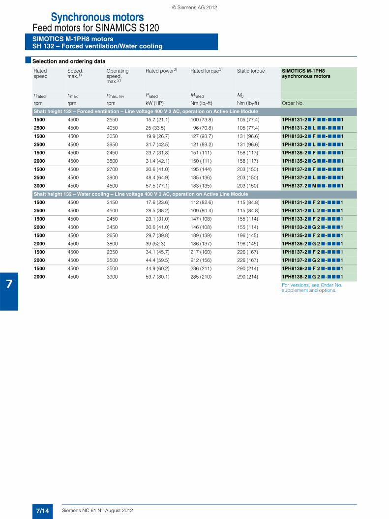
Synchronous motorsFeed motors for SINAMICS S120SIMOTICS M-1PH8 motorsSH 132 – Forced ventilation/Water cooling
7/14 Siemens NC 61 N · August 2012
7
■ Selection and ordering data
Ratedspeed
Speed, max.1)
Operating speed, max.2)
Rated power3) Rated torque3) Static torque SIMOTICS M-1PH8 synchronous motors
nrated nmax nmax, Inv Prated Mrated M0
rpm rpm rpm kW (HP) Nm (lbf-ft) Nm (lbf-ft) Order No.
Shaft height 132 – Forced ventilation – Line voltage 400 V 3 AC, operation on Active Line Module
1500 4500 2550 15.7 (21.1) 100 (73.8) 105 (77.4) 1PH8131-2■ F ■ ■-■ ■ ■1
2500 4500 4050 25 (33.5) 96 (70.8) 105 (77.4) 1PH8131-2■ L ■ ■-■ ■ ■1
1500 4500 3050 19.9 (26.7) 127 (93.7) 131 (96.6) 1PH8133-2■ F ■ ■-■ ■ ■1
2500 4500 3950 31.7 (42.5) 121 (89.2) 131 (96.6) 1PH8133-2■ L ■ ■-■ ■ ■1
1500 4500 2450 23.7 (31.8) 151 (111) 158 (117) 1PH8135-2■ F ■ ■-■ ■ ■1
2000 4500 3500 31.4 (42.1) 150 (111) 158 (117) 1PH8135-2■ G ■ ■-■ ■ ■1
1500 4500 2700 30.6 (41.0) 195 (144) 203 (150) 1PH8137-2■ F ■ ■-■ ■ ■1
2500 4500 3900 48.4 (64.9) 185 (136) 203 (150) 1PH8137-2■ L ■ ■-■ ■ ■1
3000 4500 4500 57.5 (77.1) 183 (135) 203 (150) 1PH8137-2■ M ■ ■-■ ■ ■1
Shaft height 132 – Water cooling – Line voltage 400 V 3 AC, operation on Active Line Module
1500 4500 3150 17.6 (23.6) 112 (82.6) 115 (84.8) 1PH8131-2■ F 2 ■-■ ■ ■1
2500 4500 4500 28.5 (38.2) 109 (80.4) 115 (84.8) 1PH8131-2■ L 2 ■-■ ■ ■1
1500 4500 2450 23.1 (31.0) 147 (108) 155 (114) 1PH8133-2■ F 2 ■-■ ■ ■1
2000 4500 3450 30.6 (41.0) 146 (108) 155 (114) 1PH8133-2■ G 2 ■-■ ■ ■1
1500 4500 2650 29.7 (39.8) 189 (139) 196 (145) 1PH8135-2■ F 2 ■-■ ■ ■1
2000 4500 3800 39 (52.3) 186 (137) 196 (145) 1PH8135-2■ G 2 ■-■ ■ ■1
1500 4500 2350 34.1 (45.7) 217 (160) 226 (167) 1PH8137-2■ F 2 ■-■ ■ ■1
2000 4500 3500 44.4 (59.5) 212 (156) 226 (167) 1PH8137-2■ G 2 ■-■ ■ ■1
1500 4500 3500 44.9 (60.2) 286 (211) 290 (214) 1PH8138-2■ F 2 ■-■ ■ ■1
2000 4500 3900 59.7 (80.1) 285 (210) 290 (214) 1PH8138-2■ G 2 ■-■ ■ ■1
For versions, see Order No. supplement and options.
© Siemens AG 2012

Synchronous motorsFeed motors for SINAMICS S120
SIMOTICS M-1PH8 motorsSH 132 – Forced ventilation/Water cooling
7/15Siemens NC 61 N · August 2012
7
Motor type(repeated)
Effi-ciency
Moment of inertia
Weight, approx.
Ratedcurrent3)
Stallcurrent
Terminal box
SINAMICS S120 Motor Module
Rated output current3)4)
For additional versions and components, see section SINAMICS S120 drive systemη J m Irated I0 Irated
% kgm2 (lbf-in-s2) kg (lb) A A Type A Order No.
1PH8131-2.F... 94.4 0.0446 (0.39) 85 (187) 29 30 gk833 30 6SL312■-1TE23-0AA3
1PH8131-2.L... 94.8 0.0446 (0.39) 85 (187) 44 48 gk833 45 6SL312■-1TE24-5AA3
1PH8133-2.F... 94.8 0.0600 (0.53) 103 (227) 44 45 gk833 45 6SL312■-1TE24-5AA3
1PH8133-2.L... 95.1 0.0600 (0.53) 103 (227) 55 59 gk833 60 6SL312■-1TE26-0AA3
1PH8135-2.F... 95.2 0.0750 (0.66) 120 (265) 43 44 gk833 45 6SL312■-1TE24-5AA3
1PH8135-2.G... 95.3 0.0750 (0.66) 120 (265) 59 63 gk833 60 6SL312■-1TE26-0AA3
1PH8137-2.F... 95.2 0.0885 (0.78) 136 (300) 60 62 gk833 60 6SL312■-1TE26-0AA3
1PH8137-2.L... 95.4 0.0885 (0.78) 136 (300) 83 895) gk833 85 6SL312■-1TE28-5AA3
1PH8137-2.M... 95.3 0.0885 (0.78) 136 (300) 104 1155) gk833 132 6SL312■-1TE31-3AA3
1PH8131-2.F2... 94.6 0.0446 (0.39) 102 (225) 40 41 gk843 45 6SL312■-1TE24-5AA3
1PH8131-2.L2... 94.8 0.0446 (0.39) 102 (225) 57 60 gk843 60 6SL312■-1TE26-0AA3
1PH8133-2.F2... 94.7 0.0600 (0.53) 120 (265) 42 43 gk843 45 6SL312■-1TE24-5AA3
1PH8133-2.G2... 95.0 0.0600 (0.53) 120 (265) 57 61 gk843 60 6SL312■-1TE26-0AA3
1PH8135-2.F2... 95.0 0.0750 (0.66) 138 (304) 57 59 gk843 60 6SL312■-1TE26-0AA3
1PH8135-2.G2... 95.2 0.0750 (0.66) 138 (304) 81 855) gk843 85 6SL312■-1TE28-5AA3
1PH8137-2.F2... 95.1 0.0885 (0.78) 153 (337) 58 60 gk843 60 6SL312■-1TE26-0AA3
1PH8137-2.G2... 95.4 0.0885 (0.78) 153 (337) 85 905) gk843 85 6SL312■-1TE28-5AA3
1PH8138-2.F2... 95.8 0.0885 (0.78) 156 (344) 118 1205) gk843 132 6SL312■-1TE31-3AA3
1PH8138-2.G2... 96.0 0.0885 (0.78) 156 (344) 131 1335) gk843 132 6SL312■-1TE31-3AA3
Format:Booksize 1
Cooling:Internal air cooling External air cooling
01
Motor Module:Single Motor Module 1
1) Maximum speed that must not be exceeded.2) Maximum permissible operating speed based on the induced voltage in the motor and the voltage stability of the Motor Module
(without protective circuit).3) For duty type S1.4) The rated pulse frequencies must be taken into account. The rated motor data is valid for 4 kHz.5) From approximately 85 A, the top power connector connection type is not possible (15th data position E to H).
© Siemens AG 2012

Synchronous motorsFeed motors for SINAMICS S120SIMOTICS M-1PH8 motorsSH 160 – Forced ventilation/Water cooling
7/16 Siemens NC 61 N · August 2012
7
■ Selection and ordering data
Ratedspeed
Speed, max.1)
Operating speed, max.2)
Rated power3) Rated torque3) Static torque SIMOTICS M-1PH8 synchronous motors
nrated nmax nmax, Inv Prated Mrated M0
rpm rpm rpm kW (HP) Nm (lbf-ft) Nm (lbf-ft) Order No.
Shaft height 160 – Forced ventilation – Line voltage 400 V 3 AC, operation on Active Line Module
1500 4000 2600 61 (81.1) 390 (288) 440 1PH8165-2■F■■-■■■1
2500 4000 3900 84 (113) 320 (236) 440 1PH8165-2■L■■-■■■1
1500 4000 2600 69 (92.5) 435 (321) 500 1PH8167-2■F■■-■■■1
2500 4000 4000 95 (127) 360 (266) 500 1PH8167-2■L■■-■■■1
Shaft height 160 – Water cooling – Line voltage 400 V 3 AC, operation on Active Line Module
1500 4000 2400 59 (79.1) 375 (277) 440 1PH8164-2■F 2 ■-■■■1
2500 4000 4000 88 (118) 335 (247) 440 1PH8164-2■L 2 ■-■■■1
1500 4000 2600 74 (99.2) 475 (350) 550 1PH8166-2■F 2 ■-■■■1
2500 4000 3900 102 (137) 390 (288) 550 1PH8166-2■L 2 ■-■■■1
1500 4000 2600 84 (113) 530 (391) 620 1PH8168-2■F 2 ■-■■■1
2500 4000 4000 119 (160) 455 (336) 520 1PH8168-2■L 2 ■-■■■1
For versions, see Order No. supplement and options.
© Siemens AG 2012

Synchronous motorsFeed motors for SINAMICS S120
SIMOTICS M-1PH8 motorsSH 160 – Forced ventilation/Water cooling
7/17Siemens NC 61 N · August 2012
7
Motor type(repeated)
Effi-ciency
Moment of inertia
Weight, approx.
Rated current
Stallcurrent3)
Terminal box
SINAMICS S120 Motor Module
Rated output current3)4)
For additional versions and components, see section SINAMICS S120 drive systemη J m Irated I0 Irated
% kgm2 (lbf-in-s2) kg (lb) A A Type A Order No.
1PH8165-2.F... 94 0.216 (1.912) 218 (481) 119 126 gk874 132 6SL312 ■-1TE31-3AA3
1PH8165-2.L... 95.5 0.216 (1.912) 218 (481) 148 188 gk874 200 6SL312 ■-1TE32-0AA4
1PH8167-2.F... 94 0.244 (2.160) 240 (529) 133 143 gk874 1325) 6SL312 ■-1TE31-3AA3
1PH8167-2.L... 95.5 0.244 (2.160) 240 (529) 177 230 gk874 2005) 6SL312 ■-1TE32-0AA4
1PH8164-2.F2... 94 0.175 (1.549) 224 (494) 111 118 gk874 132 6SL312 ■-1TE31-3AA3
1PH8164-2.L2... 95.5 0.175 (1.549) 224 (494) 165 205 gk874 2005) 6SL312 ■-1TE32-0AA4
1PH8166-2.F2... 94 0.216 (1.912) 257 (567) 148 159 gk874 200 6SL312 ■-1TE32-0AA4
1PH8166-2.L2... 95.5 0.216 (1.912) 257 (567) 188 240 gk874 2005) 6SL312 ■-1TE32-0AA4
1PH8168-2.F2... 94 0.244 (2.160) 279 (615) 169 179 gk874 200 6SL312 ■-1TE32-0AA4
1PH8168-2.L2... 95.5 0.244 (2.160) 279 (615) 225 240 gk874 2605) 6SL332 0 -1TE32-6AA3
Format:Booksize Chassis
13
Cooling:Internal air cooling External air cooling
01
Motor Module:Single Motor Module 1
1) Maximum speed that must not be exceeded.2) Maximum permissible operating speed based on the induced voltage in the motor and the voltage stability of the Motor Module
(without protective circuit).3) For duty type S1.4) The rated pulse frequencies must be taken into account. The rated motor data is valid for 4 kHz.5) At 4 kHz, the rated output current of the Motor Module is lower than the rated motor current or the motor stall current.
© Siemens AG 2012

Synchronous motorsFeed motors for SINAMICS S120SIMOTICS M-1PH8 motorsSH 180/SH 225 – Forced ventilation
7/18 Siemens NC 61 N · August 2012
7
■ Selection and ordering data
Ratedspeed
Speed, max.1)
Operating speed, max.2)
Rated power3) Rated torque3) Static torque SIMOTICS M-1PH8 synchronous motors
nrated nmax nmax, Inv Prated Mrated M0
rpm rpm rpm kW (HP) Nm (lbf-ft) Nm (lbf-ft) Order No.
Shaft height 180 – Forced ventilation – Line voltage 400 V 3 AC, operation on Active Line Module
700 3800 1450 33 (44.3) 450 (332) 480 (354) 1PH8184-2■C■■-■■■1
1000 3800 1950 46 (61.7) 439 (324) 480 (354) 1PH8184-2■D■■-■■■1
1500 3800 2700 70 (93.9) 446 (329) 480 (354) 1PH8184-2■F■■-■■■1
700 3800 1450 44 (59.0) 600 (443) 640 (472) 1PH8186-2■C■■-■■■1
1000 3800 2050 62 (83.1) 592 (437) 640 (472) 1PH8186-2■D■■-■■■1
1500 3800 2950 93 (125) 592 (437) 640 (472) 1PH8186-2■F■■-■■■1
Shaft height 225 – Forced ventilation – Line voltage 400 V 3 AC, operation on Active Line Module
700 3500 1450 48 (64.4) 655 (483) 708 (522) 1PH8224-2■C■■-■■■1
1000 3500 2050 68 (91.2) 649 (479) 708 (522) 1PH8224-2■D■■-■■■1
1500 3500 2900 101 (135) 643 (474) 708 (522) 1PH8224-2■F■■-■■■1
700 3500 1550 64 (85.8) 873 (644) 944 (696) 1PH8226-2■C■■-■■■1
1000 3500 1950 91 (122) 869 (641) 944 (696) 1PH8226-2■D■■-■■■1
1500 3500 2700 134 (180) 853 (629) 944 (696) 1PH8226-2■F■■-■■■1
700 3500 1450 80 (107) 1091 (805) 1180 (870) 1PH8228-2■C■■-■■■1
1000 3500 1950 113 (151) 1079 (796) 1180 (870) 1PH8228-2■D■■-■■■1
1500 3500 2900 168 (225) 1070 (789) 1180 (870) 1PH8228-2■F■■-■■■1
For versions, see Order No. supplement and options.
© Siemens AG 2012

Synchronous motorsFeed motors for SINAMICS S120
SIMOTICS M-1PH8 motorsSH 180/SH 225 – Forced ventilation
7/19Siemens NC 61 N · August 2012
7
Motor type(repeated)
Effi-ciency
Moment of inertia
Weight, approx.
Ratedcurrent
Stallcurrent3)
Terminal box SINAMICS S120 Motor Module
Rated output current3)4)
For additional versions and components, see section SINAMICS S120 drive systemη J m Irated I0 Irated
% kgm2 (lbf-in-s2) kg (lb) A A Type A Order No.
1PH8184-2.C... 93.2 0.46 (4.07) 330 (728) 80 84 1XB7322-P05 85 6SL312■-1TE28-5AA3
1PH8184-2.D... 93.7 0.46 (4.07) 330 (728) 106 115 1XB7322-P05 132 6SL312■-1TE31-3AA3
1PH8184-2.F... 95.1 0.46 (4.07) 330 (728) 148 157 1XB7322-P05 200 6SL312■-1TE32-0AA4
1PH8186-2.C... 92.4 0.60 (5.31) 400 (882) 108 115 1XB7322-P05 132 6SL312■-1TE31-3AA3
1PH8186-2.D... 94.3 0.60 (5.31) 400 (882) 148 157 1XB7322-P05 200 6SL312■-1TE32-0AA4
1PH8186-2.F... 95.2 0.60 (5.31) 405 (893) 215 229 1XB7422-P06 260 6SL3320 -1TE32-6AA3
1PH8224-2.C... 96.1 1.28 (11.33) 580 (1279) 120 128 1XB7322-P05 132 6SL312■-1TE31-3AA3
1PH8224-2.D... 96.4 1.28 (11.33) 580 (1279) 170 183 1XB7322-P05 200 6SL312■-1TE32-0AA4
1PH8224-2.F... 96.5 1.28 (11.33) 580 (1279) 235 256 1XB7422-P06 260 6SL3320 -1TE32-6AA3
1PH8226-2.C... 96.3 1.66 (14.69) 700 (1544) 170 183 1XB7322-P05 200 6SL312■-1TE32-0AA4
1PH8226-2.D... 96.7 1.66 (14.69) 700 (1544) 215 233 1XB7422-P06 260 6SL3320 -1TE32-6AA3
1PH8226-2.F... 96.7 1.66 (14.69) 700 (1544) 295 320 1XB7700-P02 3105) 6SL3320 -1TE33-1AA3
1PH8228-2.C... 96.5 2.02 (17.88) 810 (1786) 200 213 1XB7322-P05 2005) 6SL312■-1TE32-0AA4
1PH8228-2.D... 96.8 2.02 (17.88) 810 (1786) 265 284 1XB7422-P06 310 6SL3320 -1TE33-1AA3
1PH8228-2.F... 96.7 2.02 (17.88) 810 (1786) 395 427 1XB7700-P02 490 6SL3320 -1TE35-0AA3
Format:Booksize Chassis
13
Cooling:Internal air cooling External air cooling
01
Motor Module:Single Motor Module 1
1) Maximum speed that must not be exceeded.2) Maximum permissible operating speed based on the induced voltage in the motor and the voltage stability of the Motor Module
(without protective circuit).3) For duty type S1.4) The rated pulse frequencies must be taken into account. The rated motor data is valid for 4 kHz (booksize format) or 2 kHz (chassis format).5) At 2 kHz, the rated output current of the Motor Module is lower than the rated motor current or the motor stall current.
© Siemens AG 2012

Synchronous motorsFeed motors for SINAMICS S120SIMOTICS M-1PH8 motorsSH 180/SH 225 – Water cooling
7/20 Siemens NC 61 N · August 2012
7
■ Selection and ordering data
Ratedspeed
Speed, max.1)
Operating speed, max.2)
Rated power3) Rated torque3) Static torque SIMOTICS M-1PH8 synchronous motors
nrated nmax nmax, Inv Prated Mrated M0
rpm rpm rpm kW (HP) Nm (lbf-ft) Nm (lbf-ft) Order No.
Shaft height 180 – Water cooling – Line voltage 400 V 3 AC, operation on Active Line Module
700 3800 1450 42 (56.3) 573 (423) 590 (435) 1PH8184-2■ C2 ■-■ ■ ■1
1000 3800 1950 61 (81.8) 583 (430) 600 (443) 1PH8184-2■ D2 ■-■ ■ ■1
1500 3800 2700 90 (121) 573 (423) 600 (443) 1PH8184-2■ F2 ■-■ ■ ■1
2500 3800 3800 127 (170) 485 (358) 530 (391) 1PH8184-2■ L2 ■-■ ■ ■1
700 3800 1450 58 (77.8) 791 (583) 800 (590) 1PH8186-2■ C2 ■-■ ■ ■1
1000 3800 2050 80 (107) 764 (564) 800 (590) 1PH8186-2■ D2 ■-■ ■ ■1
1500 3800 2950 119 (160) 758 (559) 800 (590) 1PH8186-2■ F2 ■-■ ■ ■1
2500 3800 3800 168 (225) 642 (474) 720 (531) 1PH8186-2■ L2 ■-■ ■ ■1
Shaft height 225 – Water cooling – Line voltage 400 V 3 AC, operation on Active Line Module
700 3500 1450 72 (96.6) 982 (724) 1007 (743) 1PH8224-2■ C2 ■-■ ■ ■1
1000 3500 2050 101 (135) 964 (711) 1007 (743) 1PH8224-2■ D2 ■-■ ■ ■1
1500 3500 2900 151 (203) 961 (709) 1007 (743) 1PH8224-2■ F2 ■-■ ■ ■1
2500 3500 3500 182 (244) 695 (513) 855 (631) 1PH8224-2■ L2 ■-■ ■ ■1
700 3500 1550 95 (127) 1296 (956) 1330 (981) 1PH8226-2■ C2 ■-■ ■ ■1
1000 3500 1950 135 (181) 1289 (951) 1330 (981) 1PH8226-2■ D2 ■-■ ■ ■1
1500 3500 2700 201 (270) 1280 (944) 1330 (981) 1PH8226-2■ F2 ■-■ ■ ■1
2500 3500 3500 228 (306) 871 (642) 1170 (863) 1PH8226-2■ L2 ■-■ ■ ■1
700 3500 1450 121 (162) 1651 (1218) 1680 (1239) 1PH8228-2■ C2 ■-■ ■ ■1
1000 3500 1950 169 (227) 1614 (1190) 1680 (1239) 1PH8228-2■ D2 ■-■ ■ ■1
For versions, see Order No. supplement and options.
© Siemens AG 2012

Synchronous motorsFeed motors for SINAMICS S120
SIMOTICS M-1PH8 motorsSH 180/SH 225 – Water cooling
7/21Siemens NC 61 N · August 2012
7
Motor type(repeated)
Effi-ciency
Moment of inertia
Weight, approx.
Ratedcurrent3)
Stallcurrent3)
Terminal box SINAMICS S120 Motor Module
Rated output current3)4)
For additional versions and components, see section SINAMICS S120 drive systemη J m Irated I0 Irated
% kgm2 (lbf-in-s2) kg (lb) A A Type A Order No.
1PH8184-2.C2... 91.9 0.457 (4.04) 330 (728) 100 103 1XB7322-P05 132 6SL312■- 1TE31-3AA3
1PH8184-2.D2... 93.7 0.457 (4.04) 330 (728) 140 143 1XB7322-P05 200 6SL312■- 1TE32-0AA4
1PH8184-2.F2... 95.1 0.457 (4.04) 330 (728) 190 196 1XB7322-P05 200 6SL312■- 1TE32-0AA4
1PH8184-2.L2... 95.7 0.457 (4.04) 330 (728) 260 278 1XB7700-P02 2605) 6SL332 0 - 1TE32-6AA0
1PH8186-2.C2... 92.4 0.599 (5.30) 400 (882) 142 143 1XB7322-P05 200 6SL312■- 1TE32-0AA4
1PH8186-2.D2... 94.3 0.599 (5.30) 400 (882) 190 196 1XB7322-P05 200 6SL312■- 1TE32-0AA4
1PH8186-2.F2... 95.2 0.599 (5.30) 400 (882) 275 285 1XB7700-P02 310 6SL332 0 - 1TE33-1AA0
1PH8186-2.L2... 95.7 0.599 (5.30) 400 (882) 370 405 1XB7700-P02 3805) 6SL332 0 - 1TE33-8AA0
1PH8224-2.C2... 94.7 1.28 (11.3) 580 (1279) 180 183 1XB7322-P05 200 6SL312■- 1TE32-0AA4
1PH8224-2.D2... 95.6 1.28 (11.3) 580 (1279) 255 262 1XB7700-P02 2605) 6SL332 0 - 1TE32-6AA0
1PH8224-2.F2... 96.2 1.28 (11.3) 580 (1279) 355 367 1XB7700-P02 380 6SL332 0 - 1TE33-8AA0
1PH8224-2.L2... 96.1 1.28 (11.3) 580 (1279) 365 460 1XB7700-P02 3805) 6SL332 0 - 1TE33-8AA0
1PH8226-2.C2... 95.2 1.66 (14.7) 700 (1544) 255 260 1XB7700-P02 260 6SL332 0 - 1TE32-6AA0
1PH8226-2.D2... 96.0 1.66 (14.7) 700 (1544) 325 330 1XB7700-P02 380 6SL332 0 - 1TE33-8AA0
1PH8226-2.F2... 96.5 1.66 (14.7) 700 (1544) 445 454 1XB7700-P02 490 6SL332 0 - 1TE35-0AA0
1PH8226-2.L2... 96.2 1.66 (14.7) 700 (1544) 400 532 1XB7700-P02 490 6SL332 0 - 1TE35-0AA0
1PH8228-2.C2... 95.5 2.02 (17.9) 810 (1786) 305 306 1XB7700-P02 310 6SL332 0 - 1TE33-1AA0
1PH8228-2.D2... 96.2 2.02 (17.9) 810 (1786) 395 408 1XB7700-P02 490 6SL332 0 - 1TE35-0AA0
Format:Booksize Chassis
13
Cooling:Internal air cooling External air cooling
01
Motor Module:Single Motor Module 1
1) Maximum speed that must not be exceeded.2) Maximum permissible operating speed based on the induced voltage in the motor and the voltage stability of the Motor Module
(without protective circuit).3) For duty type S1.4) The rated pulse frequencies must be taken into account. The rated motor data is valid for 4 kHz (booksize format) or 2 kHz (chassis format).5) At 2 kHz, the rated output current of the Motor Module is lower than the rated motor current or the motor stall current.
© Siemens AG 2012

Synchronous motorsFeed motors for SINAMICS S120SIMOTICS M-1PH8 motorsSH 132/SH 160 – Forced ventilation/Water cooling
7/22 Siemens NC 61 N · August 2012
7
■ Order No. supplement for shaft heights 132 and 160
1) For definition of the vibration severity according to Siemens, see the 1PH8 Motors Configuration Manual.2) For 1PH813 limited to nmax = 4500 rpm.
For 1PH816 limited to nmax = 4000 rpm.3) For the 1PH813, power connector only possible up to a maximum stall current of I0 = 85 A.
Power connector not possible for 1PH816.
Data position of the Order No. 1 2 3 4 5 6 7 8 9 10 11 12 13 14 15 16
Shaft height 132 1 P H 8 1 3 . – 2 ■ . ■ ■ – ■ ■ ■ 1 – ZShaft height 160 1 P H 8 1 6 . – 2 ■ . ■ ■ – ■ ■ ■ 1 – Z
Overall length
Synchronous version without brake 2
Encoder systems for motors without DRIVE-CLiQ interface
Incremental encoder sin/cos 1 Vpp 2048 S/R with C and D tracks (encoder IC2048S/R) MAbsolute encoder 2048 S/R, 4096 revolutions multi-turn, with EnDat interface (encoder AM2048S/R)
E
Encoder systems for motors with DRIVE-CLiQ interface
Incremental encoder 22 bit (resolution 4194304, internal 2048 S/R) + commutation position 11 bit (encoder IC22DQ)
D
Absolute encoder 22 bit + 12 bit multi-turn (encoder AM22DQ) F
Rated speed (winding version)
Cooling Degree of protection
Forced ventilation DE NDE IP55 0Forced ventilation NDE DE IP55 1Water cooling IP65 2
Type of construction
IM B3 (IM V5, IM V6) 0IM B5 (IM V1, IM V3) 2IM B35 (IM V15, IM V35) 3
Shaft extension DE Balancing
Plain shaft – 0Fitted key Full-key 1Fitted key Half-key 2
Bearing version Vibration severity acc. toSiemens1)/EN 60034-14
Shaft and flange accuracy
Standard R/A R BStandard S/A R CAdvanced lifetime2) S/A R Q
Power connection (view of DE) Cable entry Signal connection
Terminal box top Right DE ATerminal box top Left DE BTerminal box top NDE Left CPower connector top3) Right DE EPower connector top3) Left DE FPower connector top3) NDE Left GPower connector top3) DE Left H
Version status 1
Special version (order codes are required for options) Z
© Siemens AG 2012

Synchronous motorsFeed motors for SINAMICS S120
SIMOTICS M-1PH8 motorsSH 180/SH 225 – Forced ventilation/Water cooling
7/23Siemens NC 61 N · August 2012
7
■ Order No. supplement for shaft heights 180 and 225
1) For 1PH818 continuous speed nmax = 3000 rpm. For 1PH822 continuous speed nmax = 2500 rpm.
2) For 1PH818 with flange A450.For 1PH822 with flange A550.
3) For definition of the vibration severity according to Siemens, see the 1PH8 Motors Configuration Manual.
Data position of the Order No. 1 2 3 4 5 6 7 8 9 10 11 12 13 14 15 16
Shaft height 180 1 P H 8 1 8 . – 2 ■ . ■ ■ – ■ ■ ■ 1 – ZShaft height 225 1 P H 8 2 2 . – 2 ■ . ■ ■ – ■ ■ ■ 1 – Z
Overall length
Synchronous version without brake 2
Encoder systems for motors without DRIVE-CLiQ interface
Incremental encoder sin/cos 1 Vpp 2048 S/R with C and D tracks (encoder IC2048S/R) MAbsolute encoder 2048 S/R, 4096 revolutions multi-turn, with EnDat interface (encoder AM2048S/R)
E
Encoder systems for motors with DRIVE-CLiQ interface
Incremental encoder 22 bit (resolution 4194304, internal 2048 S/R) + commutation position 11 bit (encoder IC22DQ)
D
Absolute encoder 22 bit + 12 bit multi-turn (encoder AM22DQ) F
Rated speed (winding version)
Cooling Degree of protection
Forced ventilation DE NDE IP55 0Forced ventilation NDE DE IP55 1Water cooling IP55 2
Type of construction
IM B3 (IM B6, IM B7, IM B8, IM V6) 0IM V5 1IM B5 (IM V3)1)2) 2IM B35 (IM V35)2) 3IM V15 (not possible for belt coupling)2) 5
Shaft extension DE Balancing
Plain shaft – 0Fitted key Full-key 1Fitted key Half-key 2
Bearing version Vibration severity acc. toSiemens3)/EN 60034-14
Shaft and flange accuracy
Standard R/A R BStandard S/A R CIncreased radial forces R/A R F
Power connection (view of DE) Cable entry Signal connection
Terminal box top Right DE ATerminal box top Left DE BTerminal box top NDE Right CTerminal box top DE Right D
Version status 1
Special version (order codes are required for options) Z
© Siemens AG 2012

Synchronous motorsFeed motors for SINAMICS S120SIMOTICS M-1PH8 motorsForced ventilation/Water cooling
7/24 Siemens NC 61 N · August 2012
7
■ Options
1) With options K09 or K10, another terminal box type is used for side mounting. gk843 is used instead of gk833.Only possible for IM B3 or IM B35 types of construction.
2) Only appropriate if oil spray or oil vapor is occasionally deposited on the sealing ring. 3) Regardless of the degree of protection, at high levels of atmospheric pollution, the fan must be cleaned.
Order code
Description of optionWhen ordering a motor with options, -Z should be added to the order number. The order code should also be specified for each additional required option.Order codes must not be repeated in plain text in the order.
For use with SIMOTICS Mmotors
1PH8131PH816
1PH8181PH822
A12 Additional PTC thermistor chain for alarm and tripping(Only possible for versions with terminal box.)
✔ ✔
A25 Additional KTY84 temperature sensor as reserve connected to signal terminal strip(Only possible for versions with terminal box.)
✔ Standard
G14 Fan unit with air filter (Only possible if 10th data position is 1.) ✔ ✔
K08 Encoder connector mounted opposite – ✔
K09 Terminal box or power connector NDE right ✔ –(For terminal box type, see selection guides or CAD CREATOR.) 1)
Terminal box NDE right, cable entry DE/signal connection top(Only possible if 15th data position is A.)
– ✔
K10 Terminal box or power connector NDE left ✔ –(For terminal box type, see selection guides or CAD CREATOR.) 1)
Terminal box NDE left, cable entry DE/signal connection top(Only possible if 15th data position is A.)
– ✔
K18 Radial shaft sealing ring DE2)
(Not possible if 14th data position is F.)✔ ✔
K40 Regreasing system, DE and NDE – ✔
K83 Rotation of the terminal box by + 90°(Only possible in combination with options K09 or K10.)
– ✔
K84 Rotation of the terminal box by – 90°(Only possible in combination with options K09 or K10.)
– ✔
K85 Rotation of the terminal box by + 180°(Only possible in combination with options K09 or K10.)
– ✔
K90 Version with flange size A400 – ✔
(Only possible if 12th data position is 2, 3 or 5.) With 1PH818 only
L00 Replace terminal box (standard) with the next largest terminal box(Note dimension implications, see CAD CREATOR.)
– ✔
P00 Undrilled cable entry plate – ✔
P01 Cable entry plate 3 × M63 × 1.5 (Only with terminal box type 1XB7700-P02)
– ✔
L27 NDE bearing in insulated version – ✔With 1PH818 only
Standard for 1PH822
L74 Fan in IP65 degree of protection3) ✔ –
V91 1FT6-compatible shaft extension (d × l: 48 mm × 82 mm) (1.89 in × 3.23 in)(Only possible for 1PH813.)
✔ –
Y64 Hollow shaft prepared for bearingless rotary unions with flange diameter 114 H6 ✔ –
Y84 Customer specifications on rating plate (max. 30 characters) ✔ ✔
– Paint finish (anthracite RAL 7016) Standard Standard
X01 Normal paint finish: jet black RAL 9005 ✔ ✔
X02 Normal paint finish: cream white RAL 9001 ✔ ✔
X03 Normal paint finish: reseda green RAL 6011 ✔ ✔
X04 Normal paint finish: pebble gray RAL 7032 ✔ ✔
X05 Normal paint finish: sky blue RAL 5015 ✔ ✔
X06 Normal paint finish: light ivory RAL 1015 ✔ ✔
X08 Normal paint finish: white aluminum RAL 9006 ✔ ✔
K24 Primer ✔ ✔
Pale green Red brown
K23 Special paint finish worldwidePrimer and paint finish in anthracite RAL 7016
✔ ✔
K23+X.. Special paint finish worldwidePrimer and paint finish can be selected from X01 to X08
✔ ✔
© Siemens AG 2012

Synchronous motorsFeed motors for SINAMICS S120
SIMOTICS M-1PH8 motorsForced ventilation/Water cooling
7/25Siemens NC 61 N · August 2012
7
■ Terminal box assignment, max. connectable conductor cross-sections
Terminal box type(see selection and ordering data for assignment)
Cable entry Max. outer cable diameter3)
Number of main terminals Max. cross-sectionper terminal
Max. rated current4)Power External
signals
mm (in) mm² A
gk833 1 × M40 × 1.5 1 × M16 × 1.51) 32 (1.26) Phases: 3 × M6 1 × 35 110Grounding: 2 × M6
gk843 1 × M50 × 1.5 1 × M16 × 1.51) 38 (1.50) Phases: 3 × M6 1 × 50 133Grounding: 2 × M6
gk874 1 × M63 × 1.5 1 × M16 × 1.51) 42.6 (1.68) Phases: 3 × M10 2 × 70 240Grounding: 2 × M6
1XB7322-P05 2 × M50 × 1.5 1 × M16 × 1.52) 38 (1.50) Phases: 3 × M12 2 × 50 210Grounding: 2 × Fixing eyelet
1XB7422-P06 2 × M63 × 1.5 1 × M16 × 1.52) 53 (2.09) Phases: 3 × M12 2 × 70 270Grounding: 2 × Fixing eyelet
1XB7700-P02 3 × M75 × 1.5 1 × M16 × 1.52) 68 (2.68) Phases: 3 × 2 × M12 3 × 150 700Grounding: 2 × Fixing eyelet
For terminal box type 1XB7700-P02 other cable entries (power) can be ordered via P options depending on the standard:
P00P01
Undrilled cable entry plateCable entry plate 3 × M63 × 1.5
For terminal box types 1XB7322-P05 and 1XB7422-P06, another cable entry (power) can be ordered via the P option, depending on the standard:
P00 Undrilled cable entry plate
For options K09 or K10, instead of terminal box gk833, terminal box gk843 is used mounted on the side.
1) Thread M16 × 1.5 arranged with 90° to signal connection. Thread only for option A12, A25 and 9th data position A (without encoder).2) Thread M16 × 1.5 arranged opposite to signal connection (at the side of the cable entry plate); thread only for option A12 and 9th data position A
(without encoder).3) Dependent on the design of the metric cable gland.4) Current-carrying capacity based on EN 60204-1/IEC 60364-5-52 with installation type E.
© Siemens AG 2012

Synchronous motorsFeed motors for SINAMICS S120
SIMOTICS S-1FT7 motors
7/26 Siemens NC 61 N · August 2012
7
■ Overview
SIMOTICS S-1FT7 motors forced ventilation, water cooling and natural cooling
The SIMOTICS S-1FT7 servomotors are permanent-magnet synchronous motors with very compact dimensions and an optically attractive design.
The 1FT7 motors fulfill the highest demands on dynamic perfor-mance, speed setting range, shaft and flange accuracy. They are equipped with state-of-the-art encoder technology and opti-mized for operation on our fully digital drive and control systems.
Natural cooling, forced ventilation or water cooling are available as cooling types. With the natural cooling method, heat is dissi-pated through the surface of the motor, whereas with the forced ventilation method, heat is forced out by means of built-on fans. Maximum cooling, and thus maximum power ratings can be achieved using water cooling.
■ Benefits
7 Excellent dynamic performance in a wide speed range thanks to high overload capability ≥ 4 × M0 with natural cooling
7 Wide speed setting range7 High robustness against vibratory and shock loads thanks to
vibration-isolated encoder mounting 7 High degree of protection – allows operation even with de-
manding ambient conditions7 Quick and easy mounting due to cross-profile and rotatable
connectors with quick-release locks7 Zero-backlash holding brake7 Extremely high efficiency7 Due to their low torque ripple, 1FT7 Compact motors are es-
pecially suited for use in machine tools that require maximum surface quality and optimum machining quality. Their compact dimensions permit mounting in confined spaces
7 1FT7 High Dynamic motors have very low rotor moments of inertia to achieve extremely good dynamic performance and very short cycle times. The1FT7 High Dynamic motors are available with forced ventilation and with water cooling, they possess high continuous performance capabilities.
■ Application
• High-performance machine tools• Machines with stringent requirements in terms of dynamic
performance and precision, e.g.: - Packaging machines- Foil extractor machines- Printing machines- Handling equipment
© Siemens AG 2012

Synchronous motorsFeed motors for SINAMICS S120
SIMOTICS S-1FT7 motors
7/27Siemens NC 61 N · August 2012
7
■ Technical specifications
Built-in encoder systems without DRIVE-CLiQ interface
Built-in encoder systems with DRIVE-CLiQ interface
S/R = signals/revolution
■ Options
When ordering a motor with options, -Z should be added to the order number.
N05 Non-standard shaft extension (dimensions as for 1FT5 motors)
For the following order numbers, naturally cooled 1FT7 servomotors (Compact) can be delivered with the shaft dimensions compatible with 1FT5 motors: • 1FT7034-5A.71-.... 1FT7042-5A.71-.... • 1FT7062-5A.71-.... 1FT7064-5A.71-.... • 1FT7082-5A.71-.... 1FT7084-5A.71-.... • 1FT7086-5A.71-.... 1FT7102-5A.71-.... • 1FT7105-5A.71-.... 1FT7108-5A.71-....
Shaft dimensions (diameter x length) according to shaft height (SH) with Option N05: • SH 36: 11 × 23 mm (0.43 × 0.91 in)• SH 48: 14 × 30 mm (0.55 × 1.18 in)• SH 63: 19 × 40 mm (0.75 × 1.57 in)
(not compatible with flange)• SH 80: 24 × 50 mm (0.94 × 1.97 in)• SH 100: 32 × 58 mm (1.26 × 2.28 in)
SIMOTICS S-1FT7 Compact/High Dynamic motor
Type of motor Permanent-magnet synchronous motor
Magnet material Rare-earth magnet materialCooling Natural cooling, forced
ventilation, water coolingTemperature monitoring KTY84 temperature sensor in the
stator windingInsulation of the stator winding
in accordance with EN 60034-1(IEC 60034-1)
Temperature class 155 (F) for a winding temperature rise of ΔT = 100 K at an ambient temperature of 40 °C (104 °F).For water cooling, max. inlet temperature 30 °C (86 °F). Avoid condensation.
Type of constructionin accordance with EN 60034-7 (IEC 60034-7)
IM B5 (IM V1, IM V3)with flange 0/flange 1 (compatible with 1FT6)
Degree of protection in accordance with EN 60034-5 (IEC 60034-5)
IP64/IP65/IP67
Shaft extension on the drive end in accordance with DIN 748-3 (IEC 60072-1)
Plain shaft/fitted key and keyway (half-key balancing)
Shaft and flange accuracy in accordance with DIN 42955 (IEC 60072-1)1)
Tolerance N/Tolerance R
Vibration severity in accordance with EN 60034-14 (IEC 60034-14)
Grade A is maintained up to rated speed/Grade R
Sound pressure level LpA (1 m) in accordance with DIN EN ISO 1680, max.Tolerance + 3 dB• 1FT703• 1FT704 ... 1FT706• 1FT708 ... 1FT710
60 dB65 dB70 dB
Connection Connectors for signals and power rotatable
Paint finish Pearl dark gray RAL 90232nd rating plate Enclosed separately Holding brake Without/withApprovals, according to cURus
Incremental encoders
IC2048S/R encoder
Incremental encoder sin/cos 1 Vpp 2048 S/R with C and D tracks
Absolute encoders
AM2048S/R encoder
Absolute encoder 2048 S/R, 4096 revolutions, multi-turn
Absolute encoders, single-turn2)
AS24DQI encoder
Absolute encoder, single-turn, 24 bit (resolution 16777216, internal 2048 S/R)
Absolute encoders, multi-turn
AM24DQI encoder
Absolute encoder 24 bit (resolution 16777216, internal 2048 S/R) + 12 bit multi-turn (traversing range 4096 revolutions)
1) Shaft extension run-out, concentricity of centering ring and shaft, and perpendicularity of flange to shaft.
2) The single-turn absolute encoder is applied for the previously used incremental encoders.
Order code
Description
N05 Non-standard shaft extension (dimensions as for 1FT5 motors)
X01 Paint finish: jet black, matt RAL 9005
X02 Paint finish: cream white RAL 9001
X03 Paint finish: reseda green RAL 6011
X04 Paint finish: pebble gray RAL 7032
X05 Paint finish: sky blue RAL 5015
X06 Paint finish: light ivory RAL 1015
X08 Paint finish: white aluminum
X09 Paint finish: anthracite RAL 7016
K23 Special paint finish for worldwide climate group: Primer and paint finish in anthracite RAL 7016
K23+X.. Special paint finish for worldwide climate group: Primer and paint finish selectable from X01 to X09
K24 Primed (unpainted)
Q12 Sealing air connection(Only in conjunction with IP67 degree of protection. Not in combination with terminal box.)
J.. Mounting of SP+ planetary gearbox (see Gearboxes)
Y84 Customer specifications on the rating plate
© Siemens AG 2012

Synchronous motorsFeed motors for SINAMICS S120SIMOTICS S-1FT7 motorsCompact core type – Natural cooling
7/28 Siemens NC 61 N · August 2012
7
■ Selection and ordering data
To select the type of construction and degree of protection, see Technical definitions.
Some 1FT7 Compact motors are available as core types. These core types can be express-delivered as replacement motors in the event of plant outages and offer the advantage of a quicker spare parts supply. For this reason, core types should be used for configuration wherever possible.
Ratedspeed
Shaftheight
Rated power Static torque Rated torque Rated current SIMOTICS S-1FT7 Compact synchronous motorsCore type
Num-ber ofpole pairs
Moment of inertiaof rotor(without brake)
Weight (without brake)
nrated SH Prated at ΔT=100 K
M0 at ΔT=100 K
Mrated at ΔT=100 K
Irated at ΔT=100 K
p J m
rpm kW(HP)
Nm (lbf-ft)
Nm (lbf-ft)
A Order No. 10-4 kgm2
(10-3 lbf-in-s2)kg (lb)
1FT7 Compact for DC link voltage 510 ... 720 V DC
2000 100 5.03 (6.75)7.96 (10.7)
30 (22.1)50 (36.9)
24 (17.7)38 (28)
1015
1FT7102-1AC77-1 7 7 11FT7105-1AC77-1 7 7 1
55
91.4 (80.9)178 (157)
26.1 (57.5)44.2 (97.5)
3000 48 1.35 (1.81) 5 (3.7) 4.3 (3.2) 2.6 1FT7044-1AF77-1 7 7 1 3 5.43 (4.81) 7.2 (15.9)
63 1.7 (2.28)2.39 (3.20)
6 (4.4)9 (6.6)
5.4 (4.0)7.6 (5.6)
3.95.2
1FT7062-1AF77-1 7 7 11FT7064-1AF77-1 7 7 1
55
7.36 (6.51)11.9 (10.5)
7.1 (15.7)9.7 (21.4)
80 3.24 (4.34)4.56 (6.11)5.65 (7.58)
13 (9.6)20 (14.8)28 (20.7)
10.3 (7.60)14.5 (10.7)18 (13.3)
6.68.5
11
1FT7082-1AF77-1 7 7 11FT7084-1AF77-1 7 7 11FT7086-1AF77-1 7 7 1
555
26.5 (23.4)45.1 (39.9)63.6 (56.2)
14 (30.9)20.8 (45.9)27.5 (60.6)
4500 80 4.82 (6.46)1)
4.71 (6.32)20 (14.8)28 (20.7)
11.5 (8.48)1)
10 (7.4)10.11)
101FT7084-1AH77-1 7 7 11FT7086-1AH77-1 7 7 1
55
45.1 (39.9)63.6 (56.2)
20.8 (45.9)27.5 (60.6)
6000 36 0.88 (1.18) 2 (1.5) 1.4 (1.0) 2.1 1FT7034-1AK77-1 7 7 1 3 0.85 (0.75) 3.8 (8.38)
63 2.13 (2.86)2)
2.59 (3.47)3)6 (4.4)9 (6.6)
3.7 (2.73)2)
5.5 (4.06)3)5.92)
6.13)1FT7062-1AK77-1 7 7 11FT7064-1AK77-1 7 7 1
55
7.36 (6.51)11.9 (10.5)
7.1 (15.7)9.7 (21.4)
Type of construction: IM B5 Flange 0Flange 1 (compatible with 1FT6)
01
Encoder systems for motors without DRIVE-CLiQ interface:
IC2048S/R encoderAM2048S/R encoder
NM
Encoder systems for motors with DRIVE-CLiQ interface:
AS24DQI encoderAM24DQI encoder
BC
Shaft extension:Plain shaftPlain shaft
Shaft and flange accuracy:Tolerance NTolerance N
Holding brake:WithoutWith
GH
Vibration severity:Grade A
Degree of protection:IP65 1
© Siemens AG 2012

Synchronous motorsFeed motors for SINAMICS S120
SIMOTICS S-1FT7 motorsCompact core type – Natural cooling
7/29Siemens NC 61 N · August 2012
7
Motor type(repeated)
Effi-ciency4)
Stall current
Calculated powerPcalc7)
SINAMICS S120 Motor Module Power cable with complete shieldMotor connection (and brake connection) via power connectorRated output
current5)Booksize formatFor additional versions and components, see section SINAMICS S120 drive system
η I0 at M0 ΔT=100 K
Pcalcat M0 ΔT=100 K
Irated Power connector
Cable cross-section6)
Pre-assembledcable
% A kW (HP)
A Order No. Size mm2 Order No.
1FT7102-1AC7...1FT7105-1AC7...
9393
12.518
6.28 (8.42)10.47 (14.0)
1818
6SL3127-7TE21-8AA36SL3127-7TE21-8AA3
1.51.5
4 × 1.54 × 2.5
6FX7002-57N21-....6FX7002-57N31-....
1FT7044-1AF7... 92 2.8 1.57 (2.11) 3 6SL3127-7TE13-0AA3 1 4 × 1.5 6FX7002-57N01-....
1FT7062-1AF7...1FT7064-1AF7...
9193
3.95.7
1.88 (2.52)2.83 (3.80)
59
6SL3127-7TE15-0AA36SL3127-7TE21-0AA3
11
4 × 1.54 × 1.5
6FX7002-57N01-....6FX7002-57N01-....
1FT7082-1AF7...1FT7084-1AF7...1FT7086-1AF7...
939393
7.61115.5
4.08 (5.47)6.28 (8.42)8.8 (11.8)
91818
6SL3127-7TE21-0AA36SL3127-7TE21-8AA36SL3127-7TE21-8AA3
111.5
4 × 1.54 × 1.54 × 2.5
6FX7002-57N01-....6FX7002-57N01-....6FX7002-57N31-....
1FT7084-1AH7...1FT7086-1AH7...
9391
15.622.4
9.42 (12.6)13.19 (17.7)
1830
6SL3127-7TE21-8AA36SL3127-1 TE23-0AA3
1.51.5
4 × 2.54 × 4
6FX7002-57N31-....6FX7002-57N41-....
1FT7034-1AK7... 90 2.7 1.26 (1.69) 3 6SL3127-7TE13-0AA3 1 4 × 1.5 6FX7002-57N01-....
1FT7062-1AK7...1FT7064-1AK7...
9091
8.49
3.77 (5.06)5.65 (7.58)
99
6SL3127-7TE21-0AA36SL3127-7TE21-0AA3
11
4 × 1.54 × 1.5
6FX7002-57N01-....6FX7002-57N01-....
Cooling:Internal air cooling External air cooling
01
Power cable:MOTION-CONNECT 800MOTION-CONNECT 500
85
Motor Module:Single Motor Module Double Motor Module
12
Without brake coresWith brake cores
CD
Length code ....
For information on the cables refer to section Connection system MOTION-CONNECT.
1) These values refer to n = 4000 rpm.2) These values refer to n = 5500 rpm.3) These values refer to n = 4500 rpm.4) Optimum efficiency in continuous duty.5) With default setting of the pulse frequency.6) The current carrying capacity of the power cables complies with EN 60204-1 for installation type C, for continuous duty at an ambient air temperature of
40 °C (104 °F).
7)P [kW] =
9550calcM [Nm] × n rated0
5250calcM [lbf-ft] × n0 ratedP [hp] =
© Siemens AG 2012

Synchronous motorsFeed motors for SINAMICS S120SIMOTICS S-1FT7 motorsCompact – Natural cooling
7/30 Siemens NC 61 N · August 2012
7
■ Selection and ordering data
To select the type of construction and degree of protection, see Technical definitions.
Ratedspeed
Shaftheight
Rated power Static torque Rated torque Rated current SIMOTICS S-1FT7 Compact synchronous motors
Num-ber ofpole pairs
Moment of inertiaof rotor(without brake)
Weight (without brake)
nrated SH Prated atΔT=100 K
M0 at ΔT=100 K
Mratedat ΔT=100 K
Iratedat ΔT=100 K
p J m
rpm kW(HP)
Nm (lbf-ft)
Nm (lbf-ft)
A Order No. 10-4 kgm2
(10-3 lbf-in-s2)kg (lb)
1FT7 Compact for DC link voltage 510 ... 720 V DC
1500 100 4.08 (5.47)6.6 (8.85)9.58 (12.8)
30 (22.1)50 (36.9)70 (51.6)
26 (19.2)42 (31.0)61 (45.0)
81316
1FT7102-5AB77-17 7 71FT7105-5AB77-17 7 71FT7108-5AB77-17 7 7
555
91.4 (80.9)178 (157)248 (219)
26.1 (57.5)44.2 (97.5)59 (130)
2000 80 2.39 (3.20)3.54 (4.75)4.71 (6.32)
13 (9.6)20 (14.8)28 (20.7)
11.4 (8.4)16.9 (12.5)22.5 (16.6)
4.98.49.2
1FT7082-5AC77-17 7 71FT7084-5AC77-17 7 71FT7086-5AC77-17 7 7
555
26.5 (23.5)45.1 (39.9)63.6 (56.3)
14 (30.9)20.8 (45.9)27.5 (60.6)
100 5.03 (6.75)7.96 (10.7)
10.5 (14.1)
30 (22.1)50 (36.9)70 (51.6)
24 (17.7)38 (28.0)50 (36.9)
101518
1FT7102-5AC77-17 7 71FT7105-5AC77-17 7 71FT7108-5AC77-17 7 7
555
91.4 (80.9)178 (157)248 (219)
26.1 (57.5)44.2 (97.5)59 (130)
3000 48 0.85 (1.14)1.35 (1.81)1.76 (2.36)
3 (2.2)5 (3.7)7 (5.2)
2.7 (2.0)4.3 (3.2)5.6 (4.1)
2.12.63.5
1FT7042-5AF77-17 7 71FT7044-5AF77-17 7 71FT7046-5AF77-17 7 7
333
2.81 (2.49)5.43 (4.81)7.52 (6.66)
4.6 (10.1)7.2 (15.9)9.3 (20.5)
63 1.7 (2.28)2.39 (3.20)2.92 (3.92)3.42 (4.59)
6 (4.4)9 (6.6)
12 (8.9)15 (11.1)
5.4 (4.0)7.6 (5.6)9.3 (6.9)
10.9 (8.0)
3.95.27.26.7
1FT7062-5AF77-17 7 71FT7064-5AF77-17 7 71FT7066-5AF77-17 7 71FT7068-5AF77-17 7 7
5555
7.36 (6.51)11.9 (10.5)16.4 (14.5)23.2 (20.5)
7.1 (15.7)9.7 (21.4)
12.3 (27.1)16.3 (35.9)
80 3.24 (4.34)4.55 (6.10)5.65 (7.58)
13 (9.6)20 (14.8)28 (20.7)
10.3 (7.6)14.5 (10.7)18 (13.3)
6.68.5
11
1FT7082-5AF77-17 7 71FT7084-5AF77-17 7 71FT7086-5AF77-17 7 7
555
26.5 (23.5)45.1 (39.9)63.6 (56.3)
14 (30.9)20.8 (45.9)27.5 (60.6)
100 6.28 (8.42)8.8 (11.8)6.28 (8.42)
30 (22.1)50 (36.9)70 (51.6)
20 (14.8)28 (20.7)20 (14.8)
121512
1FT7102-5AF77-17 7 71FT7105-5AF77-17 7 71FT7108-5AF77-17 7 7
555
91.4 (80.9)178 (157)248 (220)
26.1 (57.5)44.2 (97.5)59 (130)
Type of construction: IM B5 Flange 0Flange 1 (compatible with 1FT6)
01
Encoder systems for motors without DRIVE-CLiQ interface:
IC2048S/R encoderAM2048S/R encoder
NM
Encoder systems for motors with DRIVE-CLiQ interface:
AS24DQI encoderAM24DQI encoder
BC
Shaft extension:Fitted key and keywayFitted key and keywayFitted key and keywayFitted key and keywayPlain shaftPlain shaftPlain shaftPlain shaft
Shaft and flange accuracy:Tolerance NTolerance NTolerance RTolerance RTolerance NTolerance NTolerance RTolerance R
Holding brake:WithoutWithWithoutWithWithoutWithWithoutWith
ABDEGHKL
Vibration severity:Grade AGrade AGrade AGrade RGrade RGrade R
Degree of protection:IP64IP65IP67IP64IP65IP67
012345
© Siemens AG 2012

Synchronous motorsFeed motors for SINAMICS S120
SIMOTICS S-1FT7 motorsCompact – Natural cooling
7/31Siemens NC 61 N · August 2012
7
Motor type(repeated)
Effi-ciency1)
Stall current
Calculated powerPcalc4)
SINAMICS S120 Motor Module Power cable with complete shieldMotor connection (and brake connection) via power connectorRated output
current2)Booksize formatFor additional versions and components, see section SINAMICS S120 drive system
η I0 at M0 ΔT=100 K
Pcalcat M0 ΔT=100 K
Irated Power connector
Cable cross-section3)
Pre-assembledcable
% A kW(HP)
A Order No. Size mm2 Order No.
1FT7102-5AB7...1FT7105-5AB7...1FT7108-5AB7...
939393
91518
4.71 (6.32)7.85 (10.5)
10.99 (14.7)
91818
6SL3127-7TE21-0AA36SL3127-7TE21-8AA36SL3127-7TE21-8AA3
1.51.51.5
4 × 1.54 × 1.54 × 2.5
6FX7002-57N21-....6FX7002-57N21-....6FX7002-57N31-....
1FT7082-5AC7...1FT7084-5AC7...1FT7086-5AC7...
939393
59
10.6
2.72 (3.65)4.19 (5.62)5.86 (7.86)
59
18
6SL3127-7TE15-0AA36SL3127-7TE21-0AA36SL3127-7TE21-8AA3
111
4 × 1.54 × 1.54 × 1.5
6FX7002-57N01-....6FX7002-57N01-....6FX7002-57N01-....
1FT7102-5AC7...1FT7105-5AC7...1FT7108-5AC7...
939393
12.51825
6.28 (8.42)10.47 (14.0)14.66 (19.7)
181830
6SL3127-7TE21-8AA36SL3127-7TE21-8AA36SL3127-1 TE23-0AA3
1.51.51.5
4 × 1.54 × 2.54 × 4
6FX7002-57N21-....6FX7002-57N31-....6FX7002-57N41-....
1FT7042-5AF7...1FT7044-5AF7...1FT7046-5AF7...
929292
2.12.84
0.94 (1.26)1.57 (2.11)2.2 (2.95)
335
6SL3127-7TE13-0AA36SL3127-7TE13-0AA36SL3127-7TE15-0AA3
111
4 × 1.54 × 1.54 × 1.5
6FX7002-57N01-....6FX7002-57N01-....6FX7002-57N01-....
1FT7062-5AF7...1FT7064-5AF7...1FT7066-5AF7...1FT7068-5AF7...
91939292
3.95.78.48.3
1.88 (2.52)2.83 (3.80)3.77 (5.06)4.71 (6.32)
5999
6SL3127-7TE15-0AA36SL3127-7TE21-0AA36SL3127-7TE21-0AA36SL3127-7TE21-0AA3
1111
4 × 1.54 × 1.54 × 1.54 × 1.5
6FX7002-57N01-....6FX7002-57N01-....6FX7002-57N01-....6FX7002-57N01-....
1FT7082-5AF7...1FT7084-5AF7...1FT7086-5AF7...
939393
7.61115.5
4.08 (5.47)6.28 (8.42)8.8 (11.8)
91818
6SL3127-7TE21-0AA36SL3127-7TE21-8AA36SL3127-7TE21-8AA3
111.5
4 × 1.54 × 1.54 × 2.5
6FX7002-57N01-....6FX7002-57N01-....6FX7002-57N31-....
1FT7102-5AF7...1FT7105-5AF7...1FT7108-5AF7...
939493
182636
9.42 (12.6)15.71 (21.0)21.99 (29.5)
183045
6SL3127-7TE21-8AA36SL3127-1 TE23-0AA36SL3127-1 TE24-5AA3
1.51.51.5
4 × 2.54 × 44 × 6
6FX7002-57N31-....6FX7002-57N41-....6FX7002-57N54-....
Cooling:Internal air cooling External air cooling
01
Power cable:MOTION-CONNECT 800MOTION-CONNECT 500
85
Motor Module:Single Motor Module Double Motor Module
12
Without brake coresWith brake cores
CD
Length code ....
For information on the cables refer to section Connection system MOTION-CONNECT.
1) Optimum efficiency in continuous duty.2) With default setting of the pulse frequency.3) The current carrying capacity of the power cables complies with EN 60204-1 for installation type C, for continuous duty at an ambient air temperature of
40 °C (104 °F).
4)P [kW] =
9550calcM [Nm] × n rated0
5250calcM [lbf-ft] × n0 ratedP [hp] =
© Siemens AG 2012

Synchronous motorsFeed motors for SINAMICS S120SIMOTICS S-1FT7 motorsCompact – Natural cooling
7/32 Siemens NC 61 N · August 2012
7
■ Selection and ordering data
To select the type of construction and degree of protection, see Technical definitions.
Ratedspeed
Shaftheight
Rated power Static torque Rated torque Rated current SIMOTICS S-1FT7 Compact synchronous motors
Num-ber ofpole pairs
Moment of inertiaof rotor(without brake)
Weight (without brake)
nrated SH Prated atΔT=100 K
M0 at ΔT=100 K
Mratedat ΔT=100 K
Iratedat ΔT=100 K
p J m
rpm kW(HP)
Nm (lbf-ft)
Nm (lbf-ft)
A Order No. 10-4 kgm2
(10-3 lbf-in-s2)kg (lb)
1FT7 Compact for DC link voltage 510 ... 720 V DC
4500 48 1.32 (1.77)1) 7 (5.2) 3.6 (2.66)1) 4.71) 1FT7046-5AH77-17 7 7 3 7.52 (6.66) 9.3 (20.5)
63 2.55 (3.42)2) 12 (8.9) 6.1 (4.50)2) 7.52) 1FT7066-5AH77-17 7 7 5 16.4 (14.5) 12.3 (27.1)
80 3.77 (5.06)4.82 (6.46)2)
4.71 (6.32)
13 (9.6)20 (14.8)28 (20.7)
8 (5.9)11.5 (8.48)2)
10 (7.4)
7.810.12)
10
1FT7082-5AH77-17 7 71FT7084-5AH77-17 7 71FT7086-5AH77-17 7 7
555
26.5 (23.5)45.1 (39.9)63.6 (56.3)
14 (30.9)20.8 (45.9)27.5 (60.6)
6000 36 0.88 (1.18)1.07 (1.43)
2 (1.5)3 (2.2)
1.4 (1.0)1.7 (1.3)
2.12.4
1FT7034-5AK77-17 7 71FT7036-5AK77-17 7 7
33
0.85 (0.75)1.33 (1.18)
3.8 (8.38)5.0 (11.0)
48 1.26 (1.69)1.41 (1.89)3)
3 (2.2)5 (3.7)
2 (1.5)3 (2.21)3)
33.63)
1FT7042-5AK77-17 7 71FT7044-5AK77-17 7 7
33
2.81 (2.49)5.43 (4.81)
4.6 (10.1)7.2 (15.9)
63 2.13 (2.86)4)
2.59 (3.47)3)6 (4.4)9 (6.6)
3.7 (2.73)4)
5.5 (4.06)3)5.94)
6.13)1FT7062-5AK77-17 7 71FT7064-5AK77-17 7 7
55
7.36 (6.51)11.9 (10.5)
7.1 (15.7)9.7 (21.4)
Type of construction: IM B5 Flange 0Flange 1 (compatible with 1FT6)
01
Encoder systems for motors without DRIVE-CLiQ interface:
IC2048S/R encoderAM2048S/R encoder
NM
Encoder systems for motors with DRIVE-CLiQ interface:
AS24DQI encoderAM24DQI encoder
BC
Shaft extension:Fitted key and keywayFitted key and keywayFitted key and keywayFitted key and keywayPlain shaftPlain shaftPlain shaftPlain shaft
Shaft and flange accuracy:Tolerance NTolerance NTolerance RTolerance RTolerance NTolerance NTolerance RTolerance R
Holding brake:WithoutWithWithoutWithWithoutWithWithoutWith
ABDEGHKL
Vibration severity:Grade AGrade AGrade AGrade RGrade RGrade R
Degree of protection:IP64IP65IP67IP64IP65IP67
012345
© Siemens AG 2012

Synchronous motorsFeed motors for SINAMICS S120
SIMOTICS S-1FT7 motorsCompact – Natural cooling
7/33Siemens NC 61 N · August 2012
7.
Motor type(repeated)
Effi-ciency5)
Stall current
Calculated powerPcalc8)
SINAMICS S120 Motor Module Power cable with complete shieldMotor connection (and brake connection) via power connectorRated output
current6)Booksize formatFor additional versions and components, see section SINAMICS S120 drive system
η I0 at M0 ΔT=100 K
Pcalcat M0 ΔT=100 K
Irated Power connector
Cable cross-section7)
Pre-assembledcable
% A kW(HP)
A Order No. Size mm2 Order No.
1FT7046-5AH7... 90 8.1 3.3 (4.43) 9 6SL3127-7TE21-0AA3 1 4 × 1.5 6FX7002-57N01-....
1FT7066-5AH7... 90 13.6 5.65 (7.58) 18 6SL3127-7TE21-8AA3 1 4 × 1.5 6FX7002-57N01-....
1FT7082-5AH7...1FT7084-5AH7...1FT7086-5AH7...
939391
12.315.622.4
6.13 (8.22)9.42 (12.6)
13.19 (17.7)
181830
6SL3127-7TE21-8AA36SL3127-7TE21-8AA36SL3127- 1 TE23-0AA3
11.51.5
4 × 1.54 × 2.54 × 4
6FX7002-57N01-....6FX7002-57N31-....6FX7002-57N41-....
1FT7034-5AK7...1FT7036-5AK7...
9090
2.74.0
1.26 (1.69)1.88 (2.52)
35
6SL3127-7TE13-0AA36SL3127-7TE15-0AA3
11
4 × 1.54 × 1.5
6FX7002-57N01-....6FX7002-57N01-....
1FT7042-5AK7...1FT7044-5AK7...
9191
3.95.7
1.88 (2.52)3.14 (4.21)
59
6SL3127-7TE15-0AA36SL3127-7TE21-0AA3
11
4 × 1.54 × 1.5
6FX7002-57N01-....6FX7002-57N01-....
1FT7062-5AK7...1FT7064-5AK7...
9091
8.49
3.77 (5.06)5.65 (7.59)
99
6SL3127-7TE21-0AA36SL3127-7TE21-0AA3
11
4 × 1.54 × 1.5
6FX7002-57N01-....6FX7002-57N01-....
Cooling:Internal air cooling External air cooling
01
Power cable:MOTION-CONNECT 800MOTION-CONNECT 500
85
Motor Module:Single Motor Module Double Motor Module
12
Without brake coresWith brake cores
CD
Length code ....
For information on the cables refer to section Connection system MOTION-CONNECT.
1) These values refer to n = 3500 rpm.2) These values refer to n = 4000 rpm.3) These values refer to n = 4500 rpm.4) These values refer to n = 5500 rpm.5) Optimum efficiency in continuous duty.6) With default setting of the pulse frequency.7) The current carrying capacity of the power cables complies with EN 60204-1 for installation type C, for continuous duty at an ambient air temperature of
40 °C (104 °F).
8)P [kW] =
9550calcM [Nm] × n rated0
5250calcM [lbf-ft] × n0 ratedP [hp] =
© Siemens AG 2012

Synchronous motorsFeed motors for SINAMICS S120SIMOTICS S-1FT7 motorsCompact – Forced ventilation
7/34 Siemens NC 61 N · August 2012
7
■ Selection and ordering data
To select the type of construction and degree of protection, see Technical definitions.
Ratedspeed
Shaftheight
Rated power Static torque Rated torque Rated current SIMOTICS S-1FT7 Compact synchronous motors
Num-ber ofpole pairs
Moment of inertiaof rotor(without brake)
Weight (without brake)
nrated SH Prated at ΔT=100 K
M0 at ΔT=100 K
Mrated at ΔT=100 K
Irated at ΔT=100 K
p J m
rpm kW(HP)
Nm (lbf-ft)
Nm (lbf-ft)
A Order No. 10-4 kgm2
(10-3 lbf-in-s2)kg (lb)
1FT7 Compact for DC link voltage 510 ... 720 V DC
2000 80 5.0 (6.71)6.7 (8.98)
27 (19.9)36 (26.6)
24 (17.7)32 (23.6)
13.517
1FT7084-5SC77- 1 7 7 7
1FT7086-5SC77- 1 7 7 7
55
45 (39.8)64 (56.6)
25 (55.1)36 (79.4)
100 11.7 (15.7)15.3 (20.5)
65 (47.9)91 (67.1)
56 (41.3)73 (53.8)
2933
1FT7105-5SC77- 1 7 7 7
1FT7108-5SC77- 1 7 7 7
55
178 (158)248 (219)
50 (110)64 (141)
3000 80 7.2 (9.66)9.1 (12.2)
27 (19.9)36 (26.6)
23 (17.0)29 (21.4)
18.524
1FT7084-5SF77- 1 7 7 7
1FT7086-5SF77- 1 7 7 7
55
45 (39.8)64 (56.6)
25 (55.1)36 (79.4)
100 15.1 (20.2)18.8 (25.2)
65 (47.9)91 (67.1)
48 (35.4)60 (44.3)
3538
1FT7105-5SF77-7 7 7 7
1FT7108-5SF77-7 7 7 7
55
178 (158)248 (219)
50 (110)64 (141)
4500 80 9.9 (13.3)11.8 (15.8)
27 (19.9)36 (26.6)
21 (15.5)25 (18.4)
24.525
1FT7084-5SH77- 1 7 7 7
1FT7086-5SH77- 1 7 7 7
55
45 (39.8)64 (56.6)
25 (55.1)36 (79.4)
Type of construction: IM B5 Flange 0Flange 1 (compatible with 1FT6)
01
Connector outlet direction: Connector sizes 1 and 1.5 Rotatable connector 1
Connector size 31) Transverse rightTransverse leftAxial NDEAxial DE
1234
Terminal box/cable entry:1) Top/transverse from rightTop/transverse from leftTop/axial from NDETop/axial from DE
5678
Encoder systems for motors without DRIVE-CLiQ interface:
IC2048S/R encoderAM2048S/R encoder
NM
Encoder systems for motors with DRIVE-CLiQ interface:
AS24DQI encoderAM24DQI encoder
BC
Shaft extension:Fitted key Fitted keyFitted key Fitted keyPlain shaftPlain shaftPlain shaftPlain shaft
Shaft and flange accuracy:Tolerance NTolerance NTolerance RTolerance RTolerance NTolerance NTolerance RTolerance R
Holding brake:WithoutWithWithoutWithWithoutWithWithoutWith
ABDEGHKL
Vibration severity:Grade AGrade AGrade RGrade R
Degree of protection:2)
IP64IP65IP64IP65
0134
© Siemens AG 2012

Synchronous motorsFeed motors for SINAMICS S120
SIMOTICS S-1FT7 motorsCompact – Forced ventilation
7/35Siemens NC 61 N · August 2012
7
Motor type(repeated)
Effi-ciency3)
Stall current
Calculated powerPcalc6)
SINAMICS S120 Motor Module Power cable with complete shieldMotor connection (and brake connection) via power connectorRated output
current4)Booksize formatFor additional versions and components, see section SINAMICS S120 drive system
η I0 at M0 ΔT=100 K
Pcalcat M0 ΔT=100 K
Irated Power connector
Cable cross-section5)
Pre-assembled cable
% A kW(HP)
A Order No. Size mm2 Order No.
1FT7084-5SC7...1FT7086-5SC7...
9393
1519.5
5.7 (7.64)7.5 (10.1)
1830
6SL3127-7TE21-8AA36SL3127- 1TE23-0AA3
1.51.5
4 × 1.54 × 2.5
6FX7002-57N21-....6FX7002-57N31-....
1FT7105-5SC7...1FT7108-5SC7...
9393
3139
13.6 (18.2)19.1 (42.2)
4545
6SL3127- 1TE24-5AA36SL3127- 1TE24-5AA3
1.51.5
4 × 64 × 10
6FX7002-57N54-....6FX7002-57N64-....
1FT7084-5SF7...1FT7086-5SF7...
9493
2129
8.5 (11.4)11.3 (15.2)
3030
6SL3127- 1TE23-0AA36SL3127- 1TE23-0AA3
1.51.5
4 × 2.54 × 6
6FX7002-57N31-....6FX7002-57N51-....
1FT7105-5SF7...1FT7108-5SF7...
9494
4557
20.4 (27.4)28.6 (63.1)
4560
6SL3127- 1TE24-5AA36SL3127- 1TE26-0AA3
33
4 × 104 × 16
6FX7002-57S14-....6FX7002-57S23-....
1FT7084-5SH7...1FT7086-5SH7...
9493
30.534
12.7 (17.0)17.0 (22.8)
3045
6SL3127- 1TE23-0AA36SL3127- 1TE24-5AA3
1.51.5
4 × 64 × 6
6FX7002-57N51-....6FX7002-57N54-....
Cooling:Internal air cooling External air cooling
01
Power cable:MOTION-CONNECT 800MOTION-CONNECT 500
85
Motor Module:Single Motor Module Double Motor Module
12
Without brake coresWith brake cores
CD
Length code ....
For information on the cables refer to section Connection system MOTION-CONNECT.
1) Connector size 3 not rotatable. An alternative terminal box can be selected with connector size 3 only.2) The degree of protection refers to the motor. The built-in fan meets the requirements of degree of protection IP54.3) Optimum efficiency in continuous duty.4) With default setting of the pulse frequency.5) The current carrying capacity of the power cable complies with EN 60204-1 for installation type C, for continuous duty at an ambient air temperature of
40 °C (104 °F).
6)P [kW] =
9550calcM [Nm] × n rated0
5250calcM [lbf-ft] × n0 ratedP [hp] =
© Siemens AG 2012

Synchronous motorsFeed motors for SINAMICS S120SIMOTICS S-1FT7 motors Compact – Water cooling
7/36 Siemens NC 61 N · August 2012
7
■ Selection and ordering data
To select the type of construction and degree of protection, see Technical definitions.
Ratedspeed
Shaftheight
Rated power Static torque Rated torque Rated current SIMOTICS S-1FT7 Compact synchronous motors
Num-ber ofpole pairs
Moment of inertiaof rotor(without brake)
Weight (without brake)
nrated SH Prated atΔT=100 K
M0 at ΔT=100 K
Mratedat ΔT=100 K
Iratedat ΔT=100 K
p J m
rpm kW(HP)
Nm (lbf-ft)
Nm (lbf-ft)
A Order No. 10-4 kgm2
(10-3 lbf-in-s2)kg (lb)
1FT7 Compact for DC link voltage 510 ... 720 V DC
1500 100 7.9 (10.6)14.1 (18.9)19.6 (26.3)
50 (36.9)90 (66.4
125 (92.2)
50 (36.9)90 (66.4)
125 (92.2)
20.329.540.3
1FT7102-5WB77- 1 7 7 7
1FT7105-5WB77- 1 7 7 7
1FT7108-5WB77- 1 7 7 7
555
98.9 (87.5)191 (169)265 (235)
36.6 (80.7)54.8 (121)68.6 (151)
2000 80 4.4 (5.90)7.33 (9.83)
10.5 (14.1)
21 (15.5)35 (25.8)50 (36.9)
21 (15.5)35 (25.8)50 (36.9)
111724
1FT7082-5WC77- 1 7 7 7
1FT7084-5WC77- 1 7 7 7
1FT7086-5WC77- 1 7 7 7
555
28.9 (25.6)48.3 (42.8)67.8 (60.0)
20.7 (45.6)27.5 (60.6)34.1 (75.2)
100 10.4 (13.9)18.8 (25.2)26.2 (35.1)
50 (36.9)90 (66.4)
125 (92.2)
49.5 (36.5)90 (66.4)
125 (92.2)
29.340.847.5
1FT7102-5WC77- 1 7 7 7
1FT7105-5WC77- 1 7 7 7
1FT7108-5WC77-7 7 7 7
555
98.9 (87.5)191 (169)265 (235)
36.6 (80.7)54.8 (121)69.6 (154)
Type of construction: IM B5 Flange 0Flange 1 (compatible with 1FT6)
01
Connector outlet direction: Connector sizes 1 and 1.5 Rotatable connector 1
Connector size 31) Transverse rightTransverse leftAxial NDEAxial DE
1234
Terminal box/cable entry:1) Top/transverse from rightTop/transverse from leftTop/axial from NDETop/axial from DE
5678
Encoder systems for motors without DRIVE-CLiQ interface:
IC2048S/R encoderAM2048S/R encoder
NM
Encoder systems for motors with DRIVE-CLiQ interface:
AS24DQI encoderAM24DQI encoder
BC
Shaft extension:Fitted key and keywayFitted key and keywayFitted key and keywayFitted key and keywayPlain shaftPlain shaftPlain shaftPlain shaft
Shaft and flange accuracy:Tolerance NTolerance NTolerance RTolerance RTolerance NTolerance NTolerance RTolerance R
Holding brake:WithoutWithWithoutWithWithoutWithWithoutWith
ABDEGHKL
Vibration severity:Grade AGrade AGrade AGrade RGrade RGrade R
Degree of protection:IP64IP65IP67IP64IP65IP67
012345
© Siemens AG 2012

Synchronous motorsFeed motors for SINAMICS S120
SIMOTICS S-1FT7 motorsCompact – Water cooling
7/37Siemens NC 61 N · August 2012
7
Motor type(repeated)
Effi-ciency2)
Stall current
Calculated powerPcalc5)
SINAMICS S120 Motor Module Power cable with complete shieldMotor connection (and brake connection) via power connectorRated output
current3)Booksize formatFor additional versions and components, see section SINAMICS S120 drive system
η I0 at M0 ΔT=100 K
Pcalcat M0 ΔT=100 K
Irated Power connector
Cable cross-section4)
Pre-assembledcable
% A kW(HP)
A Order No. Size mm2 Order No.
1FT7102-5WB7...1FT7105-5WB7...1FT7108-5WB7...
939494
17.82839
7.9 (10.6)14.1 (18.9)19.6 (26.3)
183045
6SL3127-7TE21-8AA36SL3127- 1TE23-0AA36SL3127- 1TE24-5AA3
1.51.51.5
4 × 2.54 × 44 × 10
6FX7002-57N31-....6FX7002-57N41-....6FX7002-57N64-....
1FT7082-5WC7...1FT7084-5WC7...1FT7086-5WC7...
939494
10.716.523
4.4 (5.90)7.3 (9.79)
10.5 (14.1)
181830
6SL3127-7TE21-8AA36SL3127-7TE21-8AA36SL3127- 1TE23-0AA3
1.51.51.5
4 × 1.54 × 2.54 × 4
6FX7002-57N21-....6FX7002-57N31-....6FX7002-57N41-....
1FT7102-5WC7...1FT7105-5WC7...1FT7108-5WC7...
949495
25.53945.3
10.5 (14.1)18.8 (25.2)26.2 (35.1)
304545
6SL3127- 1TE23-0AA36SL3127- 1TE24-5AA36SL3127- 1TE24-5AA3
1.51.53
4 × 44 × 104 × 10
6FX7002-57N41-....6FX7002-57N64-....6FX7002-57S14-....
Cooling:Internal air cooling External air cooling
01
Power cable:MOTION-CONNECT 800MOTION-CONNECT 500
85
Motor Module:Single Motor Module Double Motor Module
12
Without brake coresWith brake cores
CD
Length code ....
For information on the cables refer to section Connection system MOTION-CONNECT.
1) Connector size 3 not rotatable. An alternative terminal box can be selected with connector size 3 only.2) Optimum efficiency in continuous duty.3) With default setting of the pulse frequency.4) The current carrying capacity of the power cables complies with EN 60204-1 for installation type C, for continuous duty at an ambient air temperature of
40 °C (104 °F).
5)P [kW] =
9550calcM [Nm] × n rated0
5250calcM [lbf-ft] × n0 ratedP [hp] =
© Siemens AG 2012

Synchronous motorsFeed motors for SINAMICS S120SIMOTICS S-1FT7 motors Compact – Water cooling
7/38 Siemens NC 61 N · August 2012
7
■ Selection and ordering data
To select the type of construction and degree of protection, see Technical definitions.
Ratedspeed
Shaftheight
Rated power Static torque Rated torque Rated current SIMOTICS S-1FT7 Compact synchronous motors
Num-ber ofpole pairs
Moment of inertiaof rotor(without brake)
Weight (without brake)
nrated SH Prated atΔT=100 K
M0 at ΔT=100 K
Mratedat ΔT=100 K
Iratedat ΔT=100 K
p J m
rpm kW(HP)
Nm (lbf-ft)
Nm (lbf-ft)
A Order No. 10-4 kgm2
(10-3 lbf-in-s2)kg (lb)
1FT7 Compact for DC link voltage 510 ... 720 V DC
3000 63 3.1 (4.16)5 (6.71)6.2 (8.31)9.3 (12.5)
10 (7.38)16 (11.8)20 (14.8)30 (22.1)
10 (7.38)16 (11.8)19.6 (14.5)29.5 (21.8)
7.812.514.419.6
1FT7062-5WF77- 1 7 7 7
1FT7064-5WF77- 1 7 7 7
1FT7066-5WF77- 1 7 7 7
1FT7068-5WF77- 1 7 7 7
5555
8.1 (7.17)12.9 (11.4)17.7 (15.7)24.8 (22.0)
11 (24.3)13.7 (30.2)16.3 (35.9)20.1 (44.3)
80 6.28 (8.42)11 (14.8)15.4 (20.7)
21 (15.5)35 (25.8)50 (36.9)
20.5 (15.1)35 (25.8)49 (36.1)
1624.236
1FT7082-5WF77- 1 7 7 7
1FT7084-5WF77- 1 7 7 7
1FT7086-5WF77- 1 7 7 7
555
28.9 (25.6)48.3 (42.8)67.8 (60.0)
20.7 (45.6)27.5 (60.6)34.1 (75.2)
100 14.3 (19.2)24.8 (33.3)34.2 (45.9)
50 (36.9)90 (66.4)
125 (92.2)
45.5 (33.6)79 (58.3)
109 (80.4)
38.849.560
1FT7102-5WF77- 1 7 7 7
1FT7105-5WF77-7 7 7 7
1FT7108-5WF77-7 7 7 7
555
98.9 (87.5)164 (145)265 (235)
36.6 (80.7)55.9 (123)69.6 (153)
4500 63 9.1 (12.2) 20 (14.8) 19.4 (14.0) 20.8 1FT7066-5WH77- 1 7 7 7 5 17.7 (15.7) 16.3 (35.9)
80 8.95 (12.0)14.6 (19.6)20.3 (27.2)
21 (15.5)35 (25.8)50 (36.9)
19 (14.0)32 (23.6)43 (31.7)
23.934.538
1FT7082-5WH77- 1 7 7 7
1FT7084-5WH77- 1 7 7 7
1FT7086-5WH77- 1 7 7 7
555
28.9 (25.6)48.3 (42.8)67.8 (60.0)
20.7 (45.6)27. 5 (60.6)34.1 (75.2)
6000 63 5.8 (7.78)8.9 (11.9)
10 (7.38)16 (11.8)
9.2 (6.79)14.2 (10.5)
12.720
1FT7062-5WK77- 1 7 7 7
1FT7064-5WK77- 1 7 7 7
55
8.1 (7.17)12.9 (11.4)
11 (24.3)13.7 (30.2)
Type of construction: IM B5 Flange 0Flange 1 (compatible with 1FT6)
01
Connector outlet direction: Connector sizes 1 and 1.5 Rotatable connector 1
Connector size 31) Transverse rightTransverse leftAxial NDEAxial DE
1234
Terminal box/cable entry:1) Top/transverse from right Top/transverse from left Top/axial from NDETop/axial from DE
5678
Encoder systems for motors without DRIVE-CLiQ interface:
IC2048S/R encoderAM2048S/R encoder
NM
Encoder systems for motors with DRIVE-CLiQ interface:
AS24DQI encoderAM24DQI encoder
BC
Shaft extension:Fitted key and keywayFitted key and keywayFitted key and keywayFitted key and keywayPlain shaftPlain shaftPlain shaftPlain shaft
Shaft and flange accuracy:Tolerance NTolerance NTolerance RTolerance RTolerance NTolerance NTolerance RTolerance R
Holding brake:WithoutWithWithoutWithWithoutWithWithoutWith
ABDEGHKL
Vibration severity:Grade AGrade AGrade AGrade RGrade RGrade R
Degree of protection:IP64IP65IP67IP64IP65IP67
012345
© Siemens AG 2012

Synchronous motorsFeed motors for SINAMICS S120
SIMOTICS S-1FT7 motorsCompact – Water cooling
7/39Siemens NC 61 N · August 2012
7
Motor type(repeated)
Effi-ciency2)
Stall current
Calculated powerPcalc6)
SINAMICS S120 Motor Module Power cable with complete shieldMotor connection (and brake connection) via power connectorRated output
current3)Booksize formatFor additional versions and components, see section SINAMICS S120 drive system
η I0 at M0 ΔT=100 K
Pcalcat M0 ΔT=100 K
Irated Power connector
Cable cross-section4)
Pre-assembledcable
% A kW(HP)
A Order No. Size mm2 Order No.
1FT7062-5WF7...1FT7064-5WF7...1FT7066-5WF7...1FT7068-5WF7...
91919193
7.411.91419
3.1 (4.16)5.0 (6.71)6.3 (8.45)9.4 (12.6)
91818185)
6SL3127-7TE21-0AA36SL3127-7TE21-8AA36SL3127-7TE21-8AA36SL3127-7TE21-8AA3
1111
4 × 1.54 × 1.54 × 1.54 × 2.5
6FX7002-57N01-....6FX7002-57N01-....6FX7002-57N01-....6FX7002-57N11-....
1FT7082-5WF7...1FT7084-5WF7...1FT7086-5WF7...
949494
162334
6.6 (8.85)11.0 (14.8)15.7 (21.1)
183045
6SL3127-7TE21-8AA36SL3127- 1TE23-0AA36SL3127- 1TE24-5AA3
1.51.51.5
4 × 2.54 × 44 × 6
6FX7002-57N31-....6FX7002-57N41-....6FX7002-57N54-....
1FT7102-5WF7...1FT7105-5WF7...1FT7108-5WF7...
959495
4053.265
15.7 (21.1)28.3 (38.0)39.3 (52.7)
456085
6SL3127- 1TE24-5AA36SL3127- 1TE26-0AA36SL3127- 1TE28-5AA3
1.533
4 × 104 × 164 × 16
6FX7002-57N64-....6FX7002-57S23-....6FX7002-57G23-....
1FT7066-5WH7... 91 19.7 9.4 (12.6) 30 6SL3127- 1TE23-0AA3 1 4 × 2.5 6FX7002-57N11-....
1FT7082-5WH7...1FT7084-5WH7...1FT7086-5WH7...
949494
2434.340.5
9.9 (13.3)16.5 (22.1)23.6 (31.6)
304545
6SL3127- 1TE23-0AA36SL3127- 1TE24-5AA36SL3127- 1TE24-5AA3
1.51.51.5
4 × 44 × 64 × 10
6FX7002-57N41-....6FX7002-57N54-....6FX7002-57N64-....
1FT7062-5WK7...1FT7064-5WK7...
9292
12.520.2
6.3 (8.5)10.1 (13.5)
1830
6SL3127-7TE21-8AA36SL3127- 1TE23-0AA3
11
4 × 1.54 × 2.5
6FX7002-57N01-....6FX7002-57N11-....
Cooling:Internal air cooling External air cooling
01
Power cable:MOTION-CONNECT 800MOTION-CONNECT 500
85
Motor Module:Single Motor Module Double Motor Module
12
Without brake coresWith brake cores
CD
Length code ....
For information on the cables refer to section Connection system MOTION-CONNECT.
1) Connector size 3 is not rotatable. An alternative terminal box can be selected with connector size 3 only.2) Optimum efficiency in continuous duty.3) With default setting of the pulse frequency.4) The current carrying capacity of the power cables complies with EN 60204-1 for installation type C, for continuous duty at an ambient air temperature of
40 °C (104 °F).5) With the specified Motor Module, at ΔT = 100 K winding temperature rise, the motor cannot be fully utilized with M0.
If a Motor Module with a higher rating is used, you must check whether the specified power cable can be connected to it.
6)P [kW] =
9550calcM [Nm] × n rated0
5250calcM [lbf-ft] × n0 ratedP [hp] =
© Siemens AG 2012

Synchronous motorsFeed motors for SINAMICS S120SIMOTICS S-1FT7 motors High Dynamic – Forced ventilation/Water cooling
7/40 Siemens NC 61 N · August 2012
7
■ Selection and ordering data
To select the type of construction and degree of protection, see Technical definitions.
Ratedspeed
Shaftheight
Rated power Static torque Rated torque Rated current SIMOTICS S-1FT7 High Dynamic synchronous motors
Num-ber ofpole pairs
Moment of inertiaof rotor(without brake)
Weight (without brake)
nrated SH Prated at ΔT=100 K
M0 at ΔT=100 K
Mrated at ΔT=100 K
Irated at ΔT=100 K
p J m
rpm kW(HP)
Nm (lbf-ft)
Nm (lbf-ft)
A Order No. 10-4 kgm2
(10-3 lbf-in-s2)kg (lb)
1FT7 High Dynamic for DC link voltage 510 ... 720 V DC – Forced ventilation
3000 63 3.8 (5.10)4.4 (5.90)
14 (10.3)17 (12.5)
12 (8.85)14 (10.3)
10.513
1FT7065-7S F 77- 1 7 7 7
1FT7067-7S F 77- 1 7 7 7
55
6.4 (5.66)8.3 (7.35)
19 (41.9)23 (50.7)
80 7.2 (9.66)10.4 (13.9)
34 (25.1)48 (35.4)
23 (17.0)33 (24.3)
2029
1FT7085-7S F 77- 1 7 7 7
1FT7087-7S F 77- 1 7 7 7
55
20.7 (18.3)27.4 (24.3)
34 (75.0)42 (92.6)
4500 63 5.2 (6.97)6.1 (8.18)
14 (10.3)17 (12.5)
11 (8.11)13 (9.59)
13.515
1FT7065-7SH77- 1 7 7 7
1FT7067-7SH77- 1 7 7 7
55
6.4 (5.66)8.3 (7.35)
19 (41.9)23 (50.7)
80 8.2 (11.0)10.8 (14.5)
34 (25.1)48 (35.4)
17.5 (12.9)23 (17.0)
22.524
1FT7085-7SH77- 1 7 7 7
1FT7087-7SH77-7 7 7 7
55
20.7 (18.3)27.4 (24.3)
34 (75.0)43 (94.8)
1FT7 High Dynamic for DC link voltage 510 ... 720 V DC – Water cooling
3000 63 5.7 (7.64)7.4 (9.92)
19 (14.0)25 (18.4)
18 (13.3)23.5 (17.3)
1521
1FT7065-7WF77- 1 7 7 7
1FT7067-7WF77- 1 7 7 7
55
6.4 (5.66)8.3 (7.35)
16 (35.3)22 (48.5)
80 11.9 (16.0)16.0 (21.5)
43 (31.7)61 (45.0)
38 (28.0)51 (37.6)
3243
1FT7085-7WF77- 1 7 7 7
1FT7087-7WF77-7 7 7 7
55
20.7 (18.3)27.4 (24.3)
32 (70.6)41 (90.4)
4500 63 7.8 (10.5)10.4 (13.9)
19 (14.0)25 (18.4)
16.5 (12.2)22 (16.2)
2025
1FT7065-7WH77- 1 7 7 7
1FT7067-7WH77- 1 7 7 7
55
6.4 (5.66)8.3 (7.35)
16 (35.3)22 (48.5)
80 15.6 (20.9)21.7 (29.1)
43 (31.7)61 (45.0)
33 (24.3)46 (33.9)
4853
1FT7085-7WH77-7 7 7 7
1FT7087-7WH77-7 7 7 7
55
20.7 (18.3)27.4 (24.3)
32 (70.6)41 (90.4)
Type of construction: IM B5 Flange 0Flange 1 (compatible with 1FT6)
01
Connector outlet direction: Connector sizes 1 and 1.5 Rotatable connector 1
Connector size 31) Transverse rightTransverse leftAxial NDEAxial DE
1234
Terminal box/cable entry:1) Top/transverse from rightTop/transverse from leftTop/axial from NDETop/axial from DE
5678
Encoder systems for motors without DRIVE-CLiQ interface:
IC2048S/R encoderAM2048S/R encoder
NM
Encoder systems for motors with DRIVE-CLiQ interface:
AS24DQI encoderAM24DQI encoder
BC
Shaft extension:Fitted key and keywayFitted key and keywayFitted key and keywayFitted key and keywayPlain shaftPlain shaftPlain shaftPlain shaft
Shaft and flange accuracy:Tolerance NTolerance NTolerance RTolerance RTolerance NTolerance NTolerance RTolerance R
Holding brake:WithoutWithWithoutWithWithoutWithWithoutWith
ABDEGHKL
Vibration severity:Grade AGrade AGrade AGrade RGrade RGrade R
Degree of protection:IP64IP65IP67 (only for water cooling)IP64IP65IP67 (only for water cooling)
012345
© Siemens AG 2012

Synchronous motorsFeed motors for SINAMICS S120
SIMOTICS S-1FT7 motorsHigh Dynamic – Forced ventilation/Water cooling
7/41Siemens NC 61 N · August 2012
7
Motor type(repeated)
Effi-ciency2)
Stall current
Calculated powerPcalc5)
SINAMICS S120 Motor Module Power cable with complete shieldMotor connection (and brake connection) via power connectorRated output
current3)Booksize formatFor additional versions and components, see section SINAMICS S120 drive system
η I0 at M0 ΔT=100 K
Pcalcat M0 ΔT=100 K
Irated Power connector
Conductorcross-section4)
Pre-assembled cable
% A kW(HP)
A Order No. Size mm2 Order No.
1FT7065-7SF7...1FT7067-7SF7...
9294
1215
4.4 (5.90)5.3 (7.11)
1818
6SL3127-7TE21-8AA36SL3127-7TE21-8AA3
1.51.5
4 × 1.54 × 1.5
6FX7002-57 N21-....6FX7002-57 N21-....
1FT7085-7SF7...1FT7087-7SF7...
9293
2840
10.7 (14.3)15.1 (20.2)
3045
6SL3127-1 TE23-0AA36SL3127-1 TE24-5AA3
1.51.5
4 × 44 × 10
6FX7002-57 N41-....6FX7002-57 N64-....
1FT7065-7SH7...1FT7067-7SH7...
9294
1619
6.6 (8.85)8.0 (10.7)
1830
6SL3127-7TE21-8AA36SL3127-1 TE23-0AA3
1.51.5
4 × 2.54 × 2.5
6FX7002-57 N31-....6FX7002-57 N31-....
1FT7085-7SH7...1FT7087-7SH7...
9293
4045
16.0 (21.5)22.6 (30.3)
4545
6SL3127-1 TE24-5AA36SL3127-1 TE24-5AA3
1.53
4 × 104 × 10
6FX7002-57 N64-....6FX7002-57 S14-....
1FT7065-7WF7...1FT7067-7WF7...
9294
1622
6.0 (8.05)7.9 (10.6)
1830
6SL3127-7TE21-8AA36SL3127-1 TE23-0AA3
1.51.5
4 × 2.54 × 4
6FX7002-57 N31-....6FX7002-57 N41-....
1FT7085-7WF7...1FT7087-7WF7...
9394
3651
13.5 (18.1)19.2 (25.7)
4560
6SL3127-1 TE24-5AA36SL3127-1 TE26-0AA3
1.53
4 × 64 × 16
6FX7002-57 N54-....6FX7002-57 S23-....
1FT7065-7WH7...1FT7067-7WH7...
9294
2228
9.0 (12.1)11.8 (15.8)
3030
6SL3127-1 TE23-0AA36SL3127-1 TE23-0AA3
1.51.5
4 × 44 × 4
6FX7002-57 N41-....6FX7002-57 N41-....
1FT7085-7WH7...1FT7087-7WH7...
9494
5867
20.3 (27.2)28.7 (38.5)
6085
6SL3127-1 TE26-0AA36SL3127-1 TE28-5AA3
33
4 × 164 × 25
6FX7002-57 S23-....6FX7002-5DG33-....
Cooling:Internal air cooling External air cooling
01
Power cable:MOTION-CONNECT 800MOTION-CONNECT 500
85
Motor Module:Single Motor Module Double Motor Module
12
Without brake coresWith brake cores
CD
Length code ....
For information on the cables refer to section Connection system MOTION-CONNECT.
1) Connector size 3 is not rotatable. An alternative terminal box can be selected with connector size 3 only.2) Optimum efficiency in continuous duty.3) With default setting of the pulse frequency.4) The current carrying capacity of the power cable complies with EN 60204-1 for installation type C, for continuous duty at an
ambient air temperature of 40 °C (104 °F).
5)P [kW] =
9550calcM [Nm] × n rated0
5250calcM [lbf-ft] × n0 ratedP [hp] =
© Siemens AG 2012

Synchronous motorsFeed motors for SINAMICS S120
SIMOTICS S-1FK7 motors
7/42 Siemens NC 61 N · August 2012
7
■ Overview
SIMOTICS S-1FK7 motors
SIMOTICS S-1FK7 motors are compact permanent-magnet synchronous motors. The available options, gearboxes and en-coders, together with the expanded product range, mean that the SIMOTICS S-1FK7 motors can be optimally adapted to any application. They therefore also satisfy the permanently increas-ing demands of state-of-the-art machine generations.
1FK7 motors can be combined with the SINAMICS S120 drive system to create a powerful system with high functionality. The integrated encoder systems for speed and position control can be selected depending on the application.
The motors are designed for operation without external ventila-tion as the heat is dissipated through the motor surface. 1FK7 motors have a high overload capability.
■ Benefits
1FK7 Compact motors offer:7 Space-saving installation due to extremely high power density 7 For universal applications7 Wide range of motors
1FK7 High Dynamic motors offer:7 Extremely high dynamic response thanks to the very low rotor
moment of inertia
1FK7 High Inertia motors offer:7 Robust closed-loop control properties for high or variable load
moment of inertia7 Minimal optimization and commissioning overhead for the
compensation of disturbances
■ Application
• Machine tools• Robots and handling systems• Wood, glass, ceramics and stone working• Packaging, plastics and textile machines• Printing machines• Auxiliary axes
© Siemens AG 2012

Synchronous motorsFeed motors for SINAMICS S120
SIMOTICS S-1FK7 motors
7/43Siemens NC 61 N · August 2012
7
■ Technical specificationsBuilt-in encoder systems without DRIVE-CLiQ interface
Built-in encoder systems with DRIVE-CLiQ interface
S/R = signals/revolution
SIMOTICS S-1FK7 Compact/High Dynamic/High Inertia motor
Type of motor Permanent-magnet synchronous motor
Magnet material Rare-earth magnet material
Cooling Natural cooling
Temperature monitoring KTY84 temperature sensor in the stator winding
Insulation of the stator winding
in accordance with EN 60034-1 (IEC 60034-1)
Temperature class 155 (F) for a winding temperature rise of ΔT = 100 K at an ambient temperature of 40 °C (104 °F)
Type of construction in accordance with EN 60034-7 (IEC 60034-7)
IM B5 (IM V1, IM V3)
Degree of protection in accordance with EN 60034-5 (IEC 60034-5)1)
IP64 (optional IP65)
Shaft extension on the drive end in accordance with DIN 748-3 (IEC 60072-1)
Plain shaft, optional shaft with fitted key (half-key balancing)
Shaft and flange accuracy in accordance with DIN 42955 (IEC 60072-1)2)
Tolerance N
Vibration severity in accordance with EN 60034-14 (IEC 60034-14)
Grade A is maintained up to rated speed
Sound pressure level LpA (1 m) in accordance with DIN EN ISO 1680, max.Tolerance + 3 dB
• 1FK701 ... 1FK704• 1FK706• 1FK708/1FK710
55 dB65 dB70 dB
Connection Connectors for signals and power
Paint finish3) Anthracite (RAL 7016)
2nd rating plate Enclosed separately
Holding brake Optional integrated holding brake (free of backlash, 24 V DC)
Approvals, according to cURus
Incremental encoders
IC2048S/R encoder
Incremental encoder sin/cos 1 Vpp 2048 S/R with C and D tracks
Absolute encoders
AM2048S/R encoder
Absolute encoder 2048 S/R, 4096 revolutions, multi-turn
AM512S/R encoder
Absolute encoder 512 S/R, 4096 revolutions, multi-turn
AM16S/R encoder
Absolute encoder 16 S/R, 4096 revolutions, multi-turn
Resolvers
Multi-pole resolver
Multi-pole resolver(number of pole pairs corresponds to number of pole pairs of the motor)
2-pole resolver
2-pole resolver
Incremental encoders/absolute encoders, single-turn4)
IC22DQ encoder
Incremental encoder 22 bit (resolution 4194304, internal 2048 S/R) + commutation position 11 bit
AS24DQI encoder
Absolute encoder, single-turn, 24 bit (resolution 16777216, internal 2048 S/R)
AS20DQI encoder
Absolute encoder, single-turn, 20 bit (resolution 1048576, internal 512 S/R)
Absolute encoders, multi-turn
AM24DQI encoder
Absolute encoder 24 bit (resolution 16777216, internal 2048 S/R) + 12 bit multi-turn (traversing range 4096 revolutions)
AM22DQ encoder
Absolute encoder 22 bit (resolution 4194304, internal 2048 S/R) + 12 bit multi-turn (traversing range 4096 revolutions)
AM20DQI/AM20DQ encoder
Absolute encoder 20 bit (resolution 1048576, internal 512 S/R) + 12 bit multi-turn (traversing range 4096 revolutions)
AM15DQ encoder
Absolute 15 bit (resolution 32768, internal 16 S/R) + 12 bit multi-turn (traversing range 4096 revolutions)
Resolvers
R15DQ resolver
Resolver 15 bit(resolution 32768, internal, multi-pole)
R14DQ resolver
Resolver 14 bit(resolution 16384, internal, 2-pole)
1) 1FK701 can be supplied only with IP54 degree of protection.2) Shaft extension run-out, concentricity of centering ring and shaft, and
perpendicularity of flange to shaft.3) 1FK702 without a paint finish as standard.4) The single-turn absolute encoder is applied for the previously used
incremental encoders.
© Siemens AG 2012

Synchronous motorsFeed motors for SINAMICS S120
SIMOTICS S-1FK7 motors
7/44 Siemens NC 61 N · August 2012
7
■ Options
When ordering a motor with options, -Z should be added to the order number.
Order code
Description
N05 Non-standard shaft extension (dimensions as for 1FT5 motors)
N16 Nickel-plated connectors and special paint application (PS Premium) for increased chemical resistance, e.g. in the food industry. (Only for 1FK7 Compact/1FK7 High Dynamic without DRIVE-CLiQ interface).
Q31 Metal rating plate instead of adhesive label
X01 Paint finish: jet black, matt RAL 90051)
X02 Paint finish: cream white RAL 90011)
X03 Paint finish: reseda green RAL 60111)
X04 Paint finish: pebble gray RAL 70321)
X05 Paint finish: sky blue RAL 50151)
X06 Paint finish: pale ivory RAL 10151)
X08 Paint finish: suitable for food grade applications White aluminum RAL 90061)
X27 Paint finish: dark pearl gray RAL 90231)
K23 Special paint finish for worldwide climate group: Primer and paint finish in anthracite RAL 70161)
K23+X.. Special paint finish for worldwide climate group: Primer and paint finish selectable from X01 to X272)
K24 Primed (unpainted)
J.. Mounting of SP+ planetary gearbox (see Gearboxes)
V.. Mounting of LP+ planetary gearbox (see Gearboxes)
1) For the paint finish, the 1FK702 motors must be ordered with 3 or 5 on the 16th data position.
2) For the primer, the 1FK702 motors must be ordered with 0 or 2 on the 16th data position.
© Siemens AG 2012

Synchronous motorsFeed motors for SINAMICS S120
SIMOTICS S-1FK7 motors
7/45Siemens NC 61 N · August 2012
7
■ Options (continued)
N05 Non-standard shaft extension (dimensions as for 1FT5 motors)
1FK7 motors are shipped with the following shaft dimensions that are compatible with 1FT5 motors:• SH 36: 11 × 23 mm (0.43 × 0.91 in)• SH 48: 14 × 30 mm (0.55 × 1.18 in)• SH 63: 19 × 40 mm (0.75 × 1.57 in) • SH 80: 24 × 50 mm (0.94 × 1.97 in)• SH 100: 32 × 58 mm (1.26 × 2.28 in)
Note: 1FK706 motors with Option N05 do not have a compatible flange with 1FT506 motors.
N16 Version for increased chemical resistance with protective properties checked according to DIN EN ISO 4628-1
Suitable for all areas with increased demands on the protective properties of the paint system. These requirements may include applications with acids (e.g. phosphoric acid), alkalis (e.g. active chlorine), disinfectants (e.g. hydrogen peroxide and per-acetic acid), saltwater and more.
Note:The paint application PS Premium has been tested with a broad spectrum of industrial cleaning products with pH values ranging from 1.5 – 13. Resistance against the acidic and alkali cleaning products used, as well as disinfectants, was proved by a mate-rial resistance test performed by ECOLAB Deutschland GmbH.
© Siemens AG 2012

Synchronous motorsFeed motors for SINAMICS S120SIMOTICS S-1FK7 motorsCompact – Natural cooling
7/46 Siemens NC 61 N · August 2012
7
■ Selection and ordering data
Ratedspeed
Shaftheight
Rated power Static torque Rated torque Rated current SIMOTICS S-1FK7 Compact synchronous motors Natural cooling
Num-ber ofpole pairs
Moment of inertia of rotor(without brake)
Weight(without brake)
nrated SH Prated at ΔT=100 K
M0 at ΔT=100 K
Mrated at ΔT=100 K
Irated at ΔT=100 K
p J m
rpm kW(HP)
Nm(lbf-in)
Nm(lbf-in)
A Order No.Standard type
10-4 kgm2
(10-3 lbf-in-s2)kg(lb)
1FK7 Compact for DC link voltage 510 ... 720 V DC
2000 48 0.6 (0.80) 3.0 (26.6) 2.8 ((24.8) 1.55 1FK7042-2AC71-17 7 7 4 2.9 (2.57) 4.6 (10.1)
63 1.1 (1.48) 6.0 (53.1) 5.3 (46.9) 2.95 1FK7060-2AC71-17 7 7 4 7.7 (6.82) 7.1 (15.7)1.5 (2.01) 8.5 (75.2) 7.0 (62.0) 2.65 1FK7062-2AC71-17 7 7 4 11.2 (9.91) 9.1 (20.1)1.9 (2.55) 11.0 (97.4) 8.9 (78.8) 4.4 1FK7063-2AC71-17 7 7 4 14.7 (13.0) 11.1 (24.5)
80 2.1 (2.82) 12.0 (106) 10.0 (88.5) 4.4 1FK7081-2AC71-17 7 7 4 20 (17.7) 12.9 (28.4)2.6 (3.49) 16.0 (142) 12.5 (111) 6.3 1FK7083-2AC71-17 7 7 4 26 (23.0) 15.6 (34.4)3.1 (4.16) 20.0 (177) 15.0 (133) 6.7 1FK7084-2AC71-17 7 7 4 32.5 (28.8) 18.3 (40.4)
100 3 (4.02) 18.0 (159) 14.5 (128) 7.1 1FK7100-2AC71-17 7 7 4 54 (47.8) 17.6 (38.8)4.3 (5.77) 27.0 (239) 20.5 (181) 9.7 1FK7101-2AC71-17 7 7 4 79 (69.9) 23.0 (50.7)5.2 (6.97) 36.0 (319) 25.0 (221) 11.0 1FK7103-2AC71-17 7 7 4 104 (92.1) 28.5 (62.8)7.7 (10.3) 48.0 (425) 37.0 (327) 16.0 1FK7105-2AC71-17 7 7 4 154 (136) 39.0 (86.0)
3000 48 0.8 (1.07) 3.0 (26.6) 2.6 (23.0) 2.0 1FK7042-2AF71-17 7 7 4 2.9 (2.57) 4.6 (10.1)
63 1.5 (2.01) 6.0 (53.1) 4.7 (41.6) 3.7 1FK7060-2AF71-17 7 7 4 7.7 (6.82) 7.1 (15.7)1.9 (2.55) 8.5 (75.2) 6.0 (53.1) 4.0 1FK7062-2AF71-17 7 7 4 11.2 (9.91) 9.1 (20.1)2.3 (3.08) 11.0 (97.4) 7.3 (64.6) 5.6 1FK7063-2AF71-17 7 7 4 14.7 (13.0) 11.1 (24.5)
80 2.1 (2.82) 8.0 (70.8) 6.8 (60.2) 4.4 1FK7080-2AF71-17 7 7 4 14.2 (12.6) 10.3 (22.7)2.7(3.62) 12.0 (106) 8.7 (77.0) 6.8 1FK7081-2AF71-17 7 7 4 20 (17.7) 12.9 (28.4)3.3 (4.43) 16.0 (142) 10.5 (92.9) 7.2 1FK7083-2AF71-17 7 7 4 26 (23.0) 15.6 (34.4)3.1 (4.16) 20.0 (177) 10.0 (88.5) 6.5 1FK7084-2AF71-17 7 7 4 32.5 (28.8) 18.3 (40.4)
100 3.8 (5.10) 18.0 (159) 12.0 (106) 8.0 1FK7100-2AF71-17 7 7 4 54 (47.8) 17.6 (38.8)4.9 (6.57) 27.0 (239) 15.5 (137) 11.6 1FK7101-2AF71-17 7 7 4 79 (69.9) 23.0 (50.7)4.4 (5.90) 36.0 (319) 14.0 (124) 11.5 1FK7103-2AF71-17 7 7 4 104 (92.1) 28.5 (62.8)8.2 (11.0) 48.0 (425) 26.0 (230) 18.0 1FK7105-2AF71-17 7 7 4 154 (136) 39.0 (86.0)
Encoder systems for motors without DRIVE-CLiQ interface:
IC2048S/R encoderAM2048S/R encoderMulti-pole resolver2-pole resolver
AEST
Encoder systems for motors with DRIVE-CLiQ interface:
AS24DQI encoderAM24DQI encoderAS20DQI encoderAM20DQI encoderR15DQ resolverR14DQ resolver
BCQRUP
Shaft extension:Fitted key Fitted keyPlain shaft Plain shaft
Shaft and flange accuracy:Tolerance N Tolerance NTolerance N Tolerance N
Holding brake:Without WithWithout With
ABGH
Degree of protection: IP64 IP65 IP65 and DE flange IP67
012
© Siemens AG 2012

Synchronous motorsFeed motors for SINAMICS S120
SIMOTICS S-1FK7 motorsCompact – Natural cooling
7/47Siemens NC 61 N · August 2012
7
Motor type(repeated)
Effi-ciency1)
Stall current
Calculated powerPcalc5)
SINAMICS S120 Motor Module Power cable with complete shieldMotor connection (and brake connection) via power connectorRated
output current2)
Booksize formatFor additional versions and components see SINAMICS S120 drive systemη I0
at M0 ΔT=100 K
Pcalcat M0 ΔT=100 K
Irated Power connector
Cable cross-section3)
Pre-assembledcable
% A kW(HP)
A Order No. Size mm2 Order No.
Line voltage 380 ... 480 V 3 AC
1FK7042-2AC71-... 88 1.6 0.6 (0.80) 3 6SL3127-7TE13-0AA3 1 4 × 1.5 6FX7002-57N01-....
1FK7060-2AC71-... 90 3.15 1.3 (1.74) 34) 6SL3127-7TE15-0AA3 1 4 × 1.5 6FX7002-57N01-....1FK7062-2AC71-... 91 3.0 1.8 (2.41) 3 6SL3127-7TE13-0AA3 1 4 × 1.5 6FX7002-57N01-....1FK7063-2AC71-... 91 5.3 2.3 (3.08) 54) 6SL3127-7TE21-0AA3 1 4 × 1.5 6FX7002-57N01-....
1FK7081-2AC71-... 93 5.0 2.5 (3.35) 5 6SL3127-7TE15-0AA3 1 4 × 1.5 6FX7002-57N01-....1FK7083-2AC71-... 93 7.5 3.4 (4.56) 9 6SL3127-7TE21-0AA3 1 4 × 1.5 6FX7002-57N01-....1FK7084-2AC71-... 93 8.5 4.2 (5.63) 9 6SL3127-7TE21-0AA3 1 4 × 1.5 6FX7002-57N01-....
1FK7100-2AC71-... 92 8.4 3.8 (5.10) 9 6SL3127-7TE21-0AA3 1 4 × 1.5 6FX7002-57N01-....1FK7101-2AC71-... 93 12.3 5.7 (7.64) 18 6SL3127-7TE21-8AA3 1.5 4 × 1.5 6FX7002-57N21-....1FK7103-2AC71-... 93 14.4 7.5 (10.1) 18 6SL3127-7TE21-8AA3 1.5 4 × 1.5 6FX7002-57N21-....1FK7105-2AC71-... 93 20.0 10.1 (13.5) 30 6SL3127-7TE23-0AA3 1.5 4 × 2.5 6FX7002-57N31-....
1FK7042-2AF71-... 89 2.2 0.9 (1.21) 3 6SL3127-7TE13-0AA3 1 4 × 1.5 6FX7002-57N01-....
1FK7060-2AF71-... 90 4.45 1.9 (2.55) 5 6SL3127-7TE15-0AA3 1 4 × 1.5 6FX7002-57N01-....1FK7062-2AF71-... 91 5.3 2.7 (3.62) 94) 6SL3127-7TE21-0AA3 1 4 × 1.5 6FX7002-57N01-....1FK7063-2AF71-... 91 8.0 3.5 (4.69) 9 6SL3127-7TE21-0AA3 1 4 × 1.5 6FX7002-57N01-....
1FK7080-2AF71-... 92 4.9 2.5 (3.35) 5 6SL3127-7TE15-0AA3 1 4 × 1.5 6FX7002-57N01-....1FK7081-2AF71-... 93 8.7 3.8 (5.10) 9 6SL3127-7TE21-0AA3 1 4 × 1.5 6FX7002-57N01-....1FK7083-2AF71-... 93 10.1 5 (6.71) 18 6SL3127-7TE21-8AA3 1 4 × 1.5 6FX7002-57N01-....1FK7084-2AF71-... 93 12.1 6.3 (8.45) 18 6SL3127-7TE21-8AA3 1 4 × 1.5 6FX7002-57N01-....
1FK7100-2AF71-... 92 11.1 5.7 (7.64) 18 6SL3127-7TE21-8AA3 1 4 × 1.5 6FX7002-57N01-....1FK7101-2AF71-... 93 18.8 8.5 (11.4) 184) 6SL3127-7TE23-8AA3 1.5 4 × 2.5 6FX7002-57N31-....1FK7103-2AF71-... 93 26.0 11.3 (15.1) 30 6SL3127-7TE23-0AA3 1.5 4 × 4 6FX7002-57N41-....1FK7105-2AF71-... 94 31.0 15.1 (20.2) 304) 6SL3127-7TE24-0AA3 1.5 4 × 6 6FX7002-57N51-....
Power cable:MOTION-CONNECT 800 PLUSMOTION-CONNECT 500
85
Without brake coresWith brake cores
CD
Length code ....
For information on the cables refer to section Connection system MOTION-CONNECT.
Cooling:Internal air cooling External air cooling
01
Motor Module:Single Motor Module Double Motor Module
12
1) Optimum efficiency in continuous duty.2) With default setting of the pulse frequency.3) The current carrying capacity of the power cables complies with EN 60204-1 for installation type C, for continuous duty at an ambient air temperature of
40 °C (104 °F). Cable cross-section for brake connection 2 x 1.5 mm2.4) With the specified Motor Module, the motor cannot be fully utilized with M0 at ΔT = 100 K winding temperature rise. If a Motor Module with a higher rating is
used, you must check whether the specified power cable can be connected to it.
5)P [kW] =
9550calcM [Nm] × n rated0
5250calcM [lbf-ft] × n0 ratedP [hp] =
© Siemens AG 2012

Synchronous motorsFeed motors for SINAMICS S120SIMOTICS S-1FK7 motorsCompact – Natural cooling
7/48 Siemens NC 61 N · August 2012
7
■ Selection and ordering data
Ratedspeed
Shaftheight
Rated power Static torque Rated torque Rated current SIMOTICS S-1FK7 Compact synchronous motors Natural cooling
Num-ber ofpole pairs
Moment of inertia of rotor(without brake)
Weight(without brake)
nrated SH Prated at ΔT=100 K
M0 at ΔT=100 K
Mrated at ΔT=100 K
Irated at ΔT=100 K
p J m
rpm kW(HP)
Nm(lbf-in)
Nm(lbf-in)
A Order No.Standard type
10-4 kgm2
(10-3 lbf-in-s2)kg(lb)
1FK7 Compact for DC link voltage 510 ... 720 V DC
4500 63 1.7 (2.28) 6.0 (53.1) 3.7 (32.7) 4.3 1FK7060-2AH71-17 7 7 4 7.7 (6.82) 7.1 (15.7)1.4 (1.88) 8.5 (75.2) 3.0 (26.6) 3.3 1FK7062-2AH71-17 7 7 4 11.2 (9.91) 9.1 (20.1)1.4 (1.88) 11.0 (97.4) 3.0 (26.6) 3.8 1FK7063-2AH71-17 7 7 4 14.7 (13.0) 11.1 (24.5)
80 2.1 (2.82) 8.0 (70.8) 4.5 (39.8) 4.8 1FK7080-2AH71-17 7 7 4 14.2 (12.6) 10.3 (22.7)1.8 (2.41) 12.0 (106) 3.8 (33.6) 4.9 1FK7081-2AH71-17 7 7 4 20 (17.7) 12.9 (28.4)1.4 (1.88) 16.0 (142) 3.0 (26.6) 3.6 1FK7083-2AH71-17 7 7 4 26 (23.0) 15.6 (34.4)
6000 36 0.5 (0.67) 1.15 (10.2) 0.8 (7.08) 1.3 1FK7032-2AK71-17 7 7 3 0.65 (0.58) 2.7 (5.95)0.6 (0.80) 1.6 (14.2) 1.0 (8.85) 1.3 1FK7034-2AK71-17 7 7 3 0.9 (0.80) 3.5 (7.72)
48 0.7 (0.94) 1.6 (14.2) 1.1 (9.74) 1.85 1FK7040-2AK71-17 7 7 4 1.6 (1.42) 3.2 (7.06)0.9 (1.21) 3.0 (26.6) 1.5 (13.3) 2.5 1FK7042-2AK71-17 7 7 4 2.9 (2.57) 4.6 (10.1)
Encoder systems for motors without DRIVE-CLiQ interface:
IC2048S/R encoderAM2048S/R encoderMulti-pole resolver2-pole resolver
AEST
Encoder systems for motors with DRIVE-CLiQ interface:
AS24DQI encoderAM24DQI encoderAS20DQI encoderAM20DQI encoderR15DQ resolverR14DQ resolver
BCQRUP
Shaft extension:Fitted key Fitted keyPlain shaft Plain shaft
Shaft and flange accuracy:Tolerance N Tolerance NTolerance N Tolerance N
Holding brake:Without WithWithout With
ABGH
Degree of protection: IP64 IP65 IP65 and DE flange IP67
012
© Siemens AG 2012

Synchronous motorsFeed motors for SINAMICS S120
SIMOTICS S-1FK7 motorsCompact – Natural cooling
7/49Siemens NC 61 N · August 2012
7
Motor type(repeated)
Effi-ciency1)
Stall current
Calculated powerPcalc4)
SINAMICS S120 Motor Module Power cable with complete shieldMotor connection (and brake connection) via power connectorRated
output current2)
Booksize formatFor additional versions and components see SINAMICS S120 drive systemη I0
at M0 ΔT=100 K
Pcalcat M0 ΔT=100 K
Irated Power connector
Cable cross-section3)
Pre-assembledcable
% A kW(HP)
A Order No. Size mm2 Order No.
Line voltage 380 ... 480 V 3 AC
1FK7060-2AH71-... 90 6.3 2.8 (3.75) 9 6SL3127-7TE21-0AA3 1 4 × 1.5 6FX7002-57N01-....1FK7062-2AH71-... 91 8.0 4 (5.36) 9 6SL3127-7TE21-0AA3 1 4 × 1.5 6FX7002-57N01-....1FK7063-2AH71-... 90 12.0 5.2 (6.97) 18 6SL3127-7TE21-8AA3 1 4 × 1.5 6FX7002-57N01-....
1FK7080-2AH71-... 92 7.4 3.8 (5.10) 9 6SL3127-7TE21-0AA3 1 4 × 1.5 6FX7002-57N01-....1FK7081-2AH71-... 93 13.1 5.7 (7.64) 18 6SL3127-7TE21-8AA3 1 4 × 1.5 6FX7002-57N01-....1FK7083-2AH71-... 93 15.0 7.5 (10.1) 18 6SL3127-7TE21-8AA3 1 4 × 1.5 6FX7002-57N01-....
1FK7032-2AK71-... 88 1.7 0.7 (0.94) 3 6SL3127-7TE13-0AA3 1 4 × 1.5 6FX7002-57N01-....1FK7034-2AK71-... 88 1.9 1 (1.34) 3 6SL3127-7TE13-0AA3 1 4 × 1.5 6FX7002-57N01-....
1FK7040-2AK71-... 88 2.35 1 (1.34) 3 6SL3127-7TE13-0AA3 1 4 × 1.5 6FX7002-57N01-....1FK7042-2AK71-... 89 4.4 1.9 (2.55) 5 6SL3127-7TE15-0AA3 1 4 × 1.5 6FX7002-57N01-....
Power cable:MOTION-CONNECT 800 PLUSMOTION-CONNECT 500
85
Without brake coresWith brake cores
CD
Length code ....
For information on the cables refer to section Connection system MOTION-CONNECT.
Cooling:Internal air cooling External air cooling
01
Motor Module:Single Motor Module Double Motor Module
12
1) Optimum efficiency in continuous duty.2) With default setting of the pulse frequency.3) The current carrying capacity of the power cables complies with EN 60204-1 for installation type C, for continuous duty at an ambient air temperature of
40 °C (104 °F). Cable cross-section for brake connection 2 x 1.5 mm2.
4)P [kW] =
9550calcM [Nm] × n rated0
5250calcM [lbf-ft] × n0 ratedP [hp] =
© Siemens AG 2012

Synchronous motorsFeed motors for SINAMICS S120SIMOTICS S-1FK7 motorsCompact – Natural cooling – 1FK701/1FK702
7/50 Siemens NC 61 N · August 2012
7
■ Selection and ordering data
Ratedspeed
Shaftheight
Rated power Static torque Rated torque Rated current SIMOTICS S-1FK7 Compact synchronous motors Natural cooling
Num-ber ofpole pairs
Moment of inertia of rotor(without brake)
Weight(without brake)
nrated SH Prated at ΔT=100 K
M0 at ΔT=100 K
Mrated at ΔT=100 K
Irated at ΔT=100 K
p J m
rpm kW(HP)
Nm(lbf-in)
Nm(lbf-in)
A Order No. 10-4 kgm2
(10-3 lbf-in-s2)kg(lb)
1FK7 Compact for DC link voltage 510 ... 720 V DC
6000 20 0.05 (0.07) 0.18 (1.59) 0.08 (0.71) 0.85 1FK7011-5AK71-17 7 7 4 0.064 (0.06) 0.9 (1.98)0.1 (0.13) 0.35 (3.10) 0.16 (1.42) 0.85 1FK7015-5AK71-17 7 7 4 0.083 (0.07) 1.1 (2.43)
28 0.38 (0.51) 0.85 (7.52) 0.6 (5.31) 1.4 1FK7022-5AK71-17 7 7 3 0.28 (0.25) 1.8 (3.97)
Encoder systems for motors without DRIVE-CLiQ interface:
IC2048S/R encoderAM512S/R encoder (only for 1FK702)AM16S/R encodermulti-pole resolver2-pole resolver
AHJST
Encoder systems for motors with DRIVE-CLiQ interface: (Only for 1FK702)1)
IC22DQ encoderAM20DQ encoderAM15DQ encoderR15DQ resolverR14DQ resolver
DLVUP
Shaft extension:Fitted key Fitted keyPlain shaft Plain shaft
Shaft and flange accuracy:Tolerance N Tolerance NTolerance N Tolerance N
Holding brake:Without WithWithout With
ABGH
Degree of protection: IP64 (only for 1FK702)IP65 and DE flange IP67 (only for 1FK702)IP54 (only for 1FK701), IP64 (only for 1FK702)IP65 and DE flange IP67 (only for 1FK702)
Paint finish:Without Without With With
0235
1) 1FK701 motors are not available with a DRIVE-CLiQ interface. The encoder systems are connected via the SMC (Sensor Module Cabinet-Mounted).
© Siemens AG 2012

Synchronous motorsFeed motors for SINAMICS S120
SIMOTICS S-1FK7 motorsCompact – Natural cooling – 1FK701/1FK702
7/51Siemens NC 61 N · August 2012
7
Motor type(repeated)
Effi-ciency1)
Stall current
Calculated powerPcalc4)
SINAMICS S120 Motor Module Power cable with complete shieldMotor connection (and brake connection) via power connectorRated
output current2)
Booksize formatFor additional versions and components see SINAMICS S120 drive systemη I0
at M0 ΔT=100 K
Pcalcat M0 ΔT=100 K
Irated Power connector
Cable cross-section3)
Pre-assembledcable
% A kW(HP)
A Order No. Size mm2 Order No.
Line voltage 380 ... 480 V 3 AC
1FK7011-5AK71-... 62 1.5 0.1 (0.13) 3 6SL3127-7TE13-0AA3 0.5 4 × 1.5 6FX5002-5DN20-....1FK7015-5AK71-... 68 1.5 0.2 (0.27) 3 6SL3127-7TE13-0AA3 0.5 4 × 1.5 6FX5002-5DN20-....
1FK7022-5AK71-... 86 1.8 0.5 (0.67) 3 6SL3127-7TE13-0AA3 1 4 × 1.5 6FX7002-57N01-....
Power cable:MOTION-CONNECT 800 PLUSMOTION-CONNECT 500
85
Without brake coresWith brake cores
CD
Length code ....
For information on the cables refer to section Connection system MOTION-CONNECT.
Cooling:Internal air cooling External air cooling
01
Motor Module:Single Motor Module Double Motor Module
12
1) Optimum efficiency in continuous duty.2) With default setting of the pulse frequency.3) The current carrying capacity of the power cables complies with EN 60204-1 for installation type C, for continuous duty at an ambient air temperature of
40 °C (104 °F). Cable cross-section for brake connection 2 x 1.5 mm2.
4)P [kW] =
9550calcM [Nm] × n rated0
5250calcM [lbf-ft] × n0 ratedP [hp] =
© Siemens AG 2012

Synchronous motorsFeed motors for SINAMICS S120SIMOTICS S-1FK7 motorsHigh Dynamic – Natural cooling
7/52 Siemens NC 61 N · August 2012
7
■ Selection and ordering data
Ratedspeed
Shaftheight
Rated power Static torque Rated torque Rated current SIMOTICS S-1FK7 High Dynamic synchronous motors Natural cooling
Num-ber ofpole pairs
Moment of inertia of rotor(without brake)
Weight(without brake)
nrated SH Prated at ΔT=100 K
M0 at ΔT=100 K
Mrated at ΔT=100 K
Irated at ΔT=100 K
p J m
rpm kW(HP)
Nm(lbf-in)
Nm(lbf-in)
A Order No. 10-4 kgm2
(10-3 lbf-in-s2)kg(lb)
1FK7 High Dynamic for DC link voltage 510 ... 720 V DC
2000 63 2.1 (2.82) 12.0 (106) 10.0 (88.5) 7.1 1FK7064-4CC71-17 7 7 3 7.5 (6.64) 15.4 (34.0)
80 3.1 (4.16) 22.0 (195) 15.0 (133) 10.0 1FK7085-4CC71-17 7 7 4 22 (19.5) 23.0 (50.7)3.8 (5.10) 28.0 (248) 18.0 (159) 9.0 1FK7086-4CC71-17 7 7 4 22 (19.5) 23.0 (50.7)
3000 48 1.2 (1.61) 4.5 (39.8) 3.7 (32.7) 3.45 1FK7044-4CF71-17 7 7 3 1.26 (1.12) 7.4 (16.3)
63 1.7 (2.28) 6.4 (56.6) 5.4 (47.8) 5.3 1FK7061-4CF71-17 7 7 3 4.1 (3.63) 9.5 (20.9)2.5 (3.35) 12.0 (106) 8.0 (70.8) 7.6 1FK7064-4CF71-17 7 7 3 7.5 (6.64) 15.4 (34.0)
80 2 (2.68) 22.0 (195) 6.5 (57.5) 7.0 1FK7085-4CF71-17 7 7 4 22 (19.5) 23.0 (50.7)2 (2.68) 28.0 (248) 6.5 (57.5) 5.7 1FK7086-4CF71-17 7 7 4 22 (19.5) 23.0 (50.7)
4500 48 1.2 (1.61) 3.5 (31.0) 2.6 (23.0) 3.3 1FK7043-4CH71-17 7 7 3 1 (0.89) 6.0 (13.2)1.4 (1.88) 4.5 (39.8) 3.0 (26.6) 3.9 1FK7044-4CH71-17 7 7 3 1.26 (1.12) 7.4 (16.3)
63 2 (2.68) 6.4 (56.6) 4.3 (38.1) 6.2 1FK7061-4CH71-17 7 7 3 4.1 (3.63) 9.5 (20.9)2.4 (3.22) 12.0 (106) 5.0 (44.3) 7.0 1FK7064-4CH71-17 7 7 3 7.5 (6.64) 15.4 (34.0)
6000 36 0.6 (0.80) 1.3 (11.5) 0.9 (7.97) 1.6 1FK7033-4CK71-17 7 7 3 0.25 (0.22) 3.0 (6.62)
48 1.3 (1.74) 3.5 (31.0) 2.0 (17.7) 3.5 1FK7043-4CK71-17 7 7 3 1 (0.89) 6.0 (13.2)
Encoder systems for motors without DRIVE-CLiQ interface:
IC2048S/R encoderAM2048S/R encoderMulti-pole resolver2-pole resolver
AEST
Encoder systems for motors with DRIVE-CLiQ interface:
AS24DQI encoderAM24DQI encoderAS20DQI encoderAM20DQI encoderR15DQ resolverR14DQ resolver
BCQRUP
Shaft extension:Fitted key Fitted keyPlain shaft Plain shaft
Shaft and flange accuracy:Tolerance N Tolerance NTolerance N Tolerance N
Holding brake:Without WithWithout With
ABGH
Degree of protection: IP64 IP65 IP65 and DE flange IP67
012
© Siemens AG 2012

Synchronous motorsFeed motors for SINAMICS S120
SIMOTICS S-1FK7 motorsHigh Dynamic – Natural cooling
7/53Siemens NC 61 N · August 2012
7
Motor type(repeated)
Effi-ciency1)
Stall current
Calculated powerPcalc4)
SINAMICS S120 Motor Module Power cable with complete shieldMotor connection (and brake connection) via power connectorRated
output current2)
Booksize formatFor additional versions and components see SINAMICS S120 drive systemη I0
at M0 ΔT=100 K
Pcalcat M0 ΔT=100 K
Irated Power connector
Cable cross-section3)
Pre-assembledcable
% A kW(HP)
A Order No. Size mm2 Order No.
Line voltage 380 ... 480 V 3 AC
1FK7064-4CC71-... 93 8.1 2.5 (3.35) 9 6SL3127-7TE21-0AA3 1 4 × 1.5 6FX7002-57N01-....
1FK7085-4CC71-... 92 13.5 4.6 (6.17) 18 6SL3127-7TE21-8AA3 1 4 × 1.5 6FX7002-57N01-....1FK7086-4CC71-... 93 13.2 5.9 (7.91) 18 6SL3127-7TE21-8AA3 1 4 × 1.5 6FX7002-57N01-....
1FK7044-4CF71-... 91 4.0 1.4 (1.88) 5 6SL3127-7TE15-0AA3 1 4 × 1.5 6FX7002-57N01-....
1FK7061-4CF71-... 93 6.1 2 (2.68) 9 6SL3127-7TE21-0AA3 1 4 × 1.5 6FX7002-57N01-....1FK7064-4CF71-... 93 10.8 3.8 (5.10) 18 6SL3127-7TE21-8AA3 1 4 × 1.5 6FX7002-57N01-....
1FK7085-4CF71-... 92 22.0 6.9 (9.25) 30 6SL3127-7TE23-0AA3 1.5 4 × 4 6FX7002-57N41-....1FK7086-4CF71-... 93 21.5 8.8 (11.8) 30 6SL3127-7TE23-0AA3 1.5 4 × 4 6FX7002-57N41-....
1FK7043-4CH71-... 90 4.1 1.6 (2.15) 5 6SL3127-7TE15-0AA3 1 4 × 1.5 6FX7002-57N01-....1FK7044-4CH71-... 91 5.4 2.1 (2.82) 9 6SL3127-7TE21-0AA3 1 4 × 1.5 6FX7002-57N01-....
1FK7061-4CH71-... 93 8.7 3 (4.02) 9 6SL3127-7TE21-0AA3 1 4 × 1.5 6FX7002-57N01-....1FK7064-4CH71-... 93 15.0 5.7 (7.64) 18 6SL3127-7TE21-8AA3 1 4 × 1.5 6FX7002-57N01-....
1FK7033-4CK71-... 88 2.1 0.8 (1.07) 3 6SL3127-7TE13-0AA3 1 4 × 1.5 6FX7002-57N01-....
1FK7043-4CK71-... 90 5.6 2.2 (2.95) 9 6SL3127-7TE21-0AA3 1 4 × 1.5 6FX7002-57N01-....
Power cable:MOTION-CONNECT 800 PLUSMOTION-CONNECT 500
85
Without brake coresWith brake cores
CD
Length code ....
For information on the cables refer to section Connection system MOTION-CONNECT.
Cooling:Internal air cooling External air cooling
01
Motor Module:Single Motor Module Double Motor Module
12
1) Optimum efficiency in continuous duty.2) With default setting of the pulse frequency.3) The current carrying capacity of the power cables complies with EN 60204-1 for installation type C, for continuous duty at an ambient air temperature of
40 °C (104 °F). Cable cross-section for brake connection 2 x 1.5 mm2.
4)P [kW] =
9550calcM [Nm] × n rated0
5250calcM [lbf-ft] × n0 ratedP [hp] =
© Siemens AG 2012

Synchronous motorsFeed motors for SINAMICS S120SIMOTICS S-1FK7 motorsHigh Inertia – Natural cooling
7/54 Siemens NC 61 N · August 2012
7
■ Selection and ordering data
Ratedspeed
Shaftheight
Rated power Static torque Rated torque Rated current SIMOTICS S-1FK7 High Inertia synchronous motors Natural cooling
Num-ber ofpole pairs
Moment of inertia of rotor(without brake)
Weight(without brake)
nrated SH Prated at ΔT=100 K
M0 at ΔT=100 K
Mrated at ΔT=100 K
Irated at ΔT=100 K
p J m
rpm kW(HP)
Nm(lbf-in)
Nm(lbf-in)
A Order No.Standard type
10-4 kgm2
(10-3 lbf-in-s2)kg(lb)
1FK7 High Inertia for DC link voltage 510 ... 720 V DC
2000 80 3.1 (4.16) 20 (14.8) 15 (11.1) 6.7 1FK7084-3BC71-17 7 7 4 99 (33.8) 23.0 (50.7)
3000 63 1.5 (2.01) 6.0 (4.43) 4.7 (3.47) 3.7 1FK7060-3BF71-17 7 7 4 12.5 (4.27) 7.9 (17.4)
1.9 (2.55) 8.5 (75.2) 6.0 (53.1) 4.0 1FK7062-3BF71-17 7 7 4 23.5 (8.06) 10.7 (23.6)
80 2.7 (3.62) 12.0 (8.85) 8.7 (6.42) 6.8 1FK7081-3BF71-17 7 7 4 49 (16.7) 15.2 (33.5)
3.1 (4.16) 20.0 (14.8) 10.0 (7.38) 6.5 1FK7084-3BF71-17 7 7 4 99 (33.8) 23.0 (50.7)
6000 48 0.9 (1.21) 3.0 (2.21) 1.5 (1.11) 2.5 1FK7042-3BK71-17 7 7 4 5.1 (4.51) 5.1 (11.2)
Encoder systems for motors without DRIVE-CLiQ interface:
IC2048S/R encoderAM2048S/R encoder
AE
Encoder systems for motors with DRIVE-CLiQ interface:
AS24DQI encoderAM24DQI encoderAS20DQI encoderAM20DQI encoder
BCQR
Shaft extension:Fitted key Fitted keyPlain shaft Plain shaft
Shaft and flange accuracy:Tolerance N Tolerance NTolerance N Tolerance N
Holding brake:Without WithWithout With
ABGH
Degree of protection: IP64 IP65 IP65 and DE flange IP67
012
© Siemens AG 2012

Synchronous motorsFeed motors for SINAMICS S120
SIMOTICS S-1FK7 motorsHigh Inertia – Natural cooling
7/55Siemens NC 61 N · August 2012
7
Motor type(repeated)
Effi-ciency1)
Stall current
Calculated powerPcalc5)
SINAMICS S120 Motor Module Power cable with complete shieldMotor connection (and brake connection) via power connectorRated
output current2)
Booksize formatFor additional versions and components see SINAMICS S120 drive systemη I0
at M0 ΔT=100 K
Pcalcat M0 ΔT=100 K
Irated Power connector
Cable cross-section3)
Pre-assembledcable
% A kW(HP)
A Order No. Size mm2 Order No.
Line voltage 380 ... 480 V 3 AC
1FK7084-3BC71-... 93 8.5 4.2 (5.63) 9 6SL3127-7TE21-0AA3 1 4 × 1.5 6FX7002-57N01-....
1FK7060-3BF71-... 90 4.45 1.9 (2.55) 5 6SL3127-7TE15-0AA3 1 4 × 1.5 6FX7002-57N01-....
1FK7062-3BF71-... 91 5.3 2.7 (3.62) 54) 6SL3127-7TE21-0AA3 1 4 × 1.5 6FX7002-57N01-....
1FK7081-3BF71-... 93 8.7 3.8 (5.10) 9 6SL3127-7TE21-0AA3 1 4 × 1.5 6FX7002-57N01-....
1FK7084-3BF71-... 93 12.1 6.3 (8.45) 18 6SL3127-7TE21-8AA3 1 4 × 1.5 6FX7002-57N01-....
1FK7042-3BK71-... 89 4.4 1.9 (2.55) 5 6SL3127-7TE15-0AA3 1 4 × 1.5 6FX7002-57N01-....
Power cable:MOTION-CONNECT 800MOTION-CONNECT 500
85
Without brake coresWith brake cores
CD
Length code ....
For information on the cables refer to section Connection system MOTION-CONNECT.
Cooling:Internal air cooling External air cooling
01
Motor Module:Single Motor Module Double Motor Module
12
1) Optimum efficiency in continuous duty.2) With default setting of the pulse frequency.3) The current carrying capacity of the power cables complies with EN 60204-1 for installation type C, for continuous duty at an ambient air temperature of
40 °C (104 °F). Cable cross-section for brake connection 2 x 1.5 mm2.4) With the specified Motor Module, the motor cannot be fully utilized with M0 at ΔT = 100 K winding temperature rise. If a Motor Module with a higher rating is
used, you must check whether the specified power cable can be connected to it.
5)P [kW] =
9550calcM [Nm] × n rated0
5250calcM [lbf-ft] × n0 ratedP [hp] =
© Siemens AG 2012

Synchronous motorsFeed motors for SINAMICS S120SIMOTICS S-1FK7 motors Compact for Power Modules 230 V 1 AC
7/56 Siemens NC 61 N · August 2012
7
■ Selection and ordering data
Ratedspeed
Shaftheight
Rated power Static torque Rated torque Rated current SIMOTICS S-1FK7 Compact synchronous motors Natural cooling
Num-ber ofpole pairs
Moment of inertia of rotor(without brake)
Weight(without brake)
nrated SH Prated at ΔT=100 K
M0 at ΔT=100 K
Mrated at ΔT=100 K
Irated at ΔT=100 K
p J m
rpm kW(HP)
Nm(lbf-in)
Nm(lbf-in)
A Order No. 10-4 kgm2
(10-3 lbf-in-s2)kg(lb)
1FK7 Compact for DC link voltage 270 V ... 330 V DC
3000 36 0.3 (0.40) 1.15 (10.2) 1.0 (8.85) 1.6 1FK7032-2AF21-17 7 7 3 0.65 (0.53) 2.7 (5.95)0.5 (0.67) 1.6 (14.2) 1.45 (12.8) 1.8 1FK7034-2AF21-17 7 7 3 0.9 (0.80) 3.5 (7.72)
48 0.8 (1.07) 3.0 (26.6) 2.6 (23.0) 3.5 1FK7042-2AF21-17 7 7 4 2.9 (2.57) 4.6 (10.1)
Encoder systems for motors without DRIVE-CLiQ interface:
IC2048S/R encoderAM2048S/R encoderMulti-pole resolver2-pole resolver
AEST
Encoder systems for motors with DRIVE-CLiQ interface:
AS24DQI encoderAM24DQI encoderAS20DQI encoderAM20DQI encoderR15DQ resolverR14DQ resolver
BCQRUP
Shaft extension:Fitted key Fitted keyPlain shaft Plain shaft
Shaft and flange accuracy:Tolerance N Tolerance NTolerance N Tolerance N
Holding brake:Without WithWithout With
ABGH
Degree of protection: IP64 IP65 IP65 and DE flange IP67
012
© Siemens AG 2012

Synchronous motorsFeed motors for SINAMICS S120
SIMOTICS S-1FK7 motorsCompact for Power Modules 230 V 1 AC
7/57Siemens NC 61 N · August 2012
7
Motor type(repeated)
Effi-ciency1)
Stall current
Calculated powerPcalc5)
SINAMICS S110/S120 blocksize format
Power cable with complete shieldMotor connection (and brake connection) via power connector
Rated output current2)
PM340 Power Module Air cooling
η I0 at M0 ΔT=100 K
Pcalcat M0 ΔT=100 K
Irated Power connector
Cable cross-section3)
Pre-assembledcable
% A kW(HP)
A Order No. Size mm2 Order No.
Line voltage 200 ... 240 V 1 AC
1FK7032-2AF21-... 85 1.7 0.4 (0.54) 2.3 6SL3210-1SB12-37A0 1 4 × 1.5 6FX7002-57G10-....1FK7034-2AF21-... 85 1.9 0.5 (0.67) 2.3 6SL3210-1SB12-37A0 1 4 × 1.5 6FX7002-57G10-....
1FK7042-2AF21-... 88 3.95 0.9 (1.21) 3.94) 6SL3210-1SB14-07A0 1 4 × 1.5 6FX7002-57G10-....
Line filter:WithoutIntegrated
UA
Power cable:MOTION-CONNECT 800 PLUSMOTION-CONNECT 500
85
Without brake coresWith brake cores
CD
Length code ....
For information on the cables refer to section Connection system MOTION-CONNECT.
1) Optimum efficiency in continuous duty.2) With default setting of the pulse frequency.3) The current carrying capacity of the power cables complies with EN 60204-1 for installation type C, for continuous duty at an ambient air temperature of
40 °C (104 °F). Cable cross-section for brake connection 2 x 1.5 mm2.4) With the specified Motor Module, the motor cannot be fully utilized with M0 at ΔT = 100 K winding temperature rise. If a Motor Module with a higher rating is
used, you must check whether the specified power cable can be connected to it.
5)P [kW] =
9550calcM [Nm] × n rated0
5250calcM [lbf-ft] × n0 ratedP [hp] =
© Siemens AG 2012

Synchronous motorsFeed motors for SINAMICS S120SIMOTICS S-1FK7 motors Compact for Power Modules 230 V 1 AC
7/58 Siemens NC 61 N · August 2012
7
■ Selection and ordering data
Ratedspeed
Shaftheight
Rated power Static torque Rated torque Rated current SIMOTICS S-1FK7 Compact synchronous motors Natural cooling
Num-ber ofpole pairs
Moment of inertia of rotor(without brake)
Weight(without brake)
nrated SH Prated at ΔT=100 K
M0 at ΔT=100 K
Mrated at ΔT=100 K
Irated at ΔT=100 K
p J m
rpm kW(HP)
Nm(lbf-in)
Nm(lbf-in)
A Order No. 10-4 kgm2
(10-3 lbf-in-s2)kg(lb)
1FK7 Compact for DC link voltage 270 ... 330 V DC
6000 20 0.05 (0.07) 0.18 (1.59) 0.08 (0.71) 0.5 1FK7011-5AK21-17 7 7 4 0.064 (0.057) 0.9 (1.98)0.1 (0.13) 0.35 (3.10) 0.16 (1.42) 0.5 1FK7015-5AK21-17 7 7 4 0.083 (0.073) 1.1 (2.43)
28 0.38 (0.51) 0.85 (7.52) 0.6 (5.31) 1.4 1FK7022-5AK21-17 7 7 3 0.28 (0.248) 1.8 (3.97)
Encoder systems for motors without DRIVE-CLiQ interface:
IC2048S/R encoderAM512S/R encoderAM16S/R encoder (only for 1FK702)Multi-pole resolver2-pole resolver
AHJST
Encoder systems for motors with DRIVE-CLiQ interface: (Only for 1FK702)
IC22DQ encoderAM20DQ encoderAM15DQ encoderR15DQ resolverR14DQ resolver
DLVUP
Shaft extension:Fitted key Fitted keyPlain shaft Plain shaft
Shaft and flange accuracy:Tolerance N Tolerance NTolerance N Tolerance N
Holding brake:Without WithWithout With
ABGH
Degree of protection: IP64 (only for 1FK702)IP65 and DE flange IP67 (only for 1FK702)IP54 (only for 1FK701), IP64 (only for 1FK702)IP65 and DE flange IP67 (only for 1FK702)
Paint finish:Without Without With With
0235
© Siemens AG 2012

Synchronous motorsFeed motors for SINAMICS S120
SIMOTICS S-1FK7 motorsCompact for Power Modules 230 V 1 AC
7/59Siemens NC 61 N · August 2012
7
Motor type(repeated)
Effi-ciency1)
Stall current
Calculated powerPcalc4)
SINAMICS S110/S120 blocksize format
Power cable with complete shieldMotor connection (and brake connection) via power connector
Rated output current2)
PM340 Power Module Air cooling
η I0 at M0 ΔT=100 K
Pcalcat M0 ΔT=100 K
Irated Power connector
Cable cross-section3)
Pre-assembledcable
% A kW(HP)
A Order No. Size mm2 Order No.
Line voltage 200 ... 240 V 1 AC
1FK7011-5AK21-... 62 0.85 0.1 (0.13) 0.9 6SL3210-1SB11-07A0 0.5 4 × 1.5 6FX5002-5DN30-....1FK7015-5AK21-... 68 0.85 0.2 (0.27) 0.9 6SL3210-1SB11-07A0 0.5 4 × 1.5 6FX5002-5DN30-....
1FK7022-5AK21-... 86 1.8 0.5 (0.67) 2.3 6SL3210-1SB12-37A0 1 4 × 1.5 6FX7002-57G10-....
Line filter:WithoutIntegrated
UA
Power cable:MOTION-CONNECT 800 PLUSMOTION-CONNECT 500
85
Without brake coresWith brake cores
CD
Length code ....
For information on the cables refer to section Connection system MOTION-CONNECT.
1) Optimum efficiency in continuous duty.2) With default setting of the pulse frequency.3) The current carrying capacity of the power cables complies with EN 60204-1 for installation type C, for continuous duty at an ambient air temperature of
40 °C (104 °F). Cable cross-section for brake connection 2 x 1.5 mm2.
4)P [kW] =
9550calcM [Nm] × n rated0
5250calcM [lbf-ft] × n0 ratedP [hp] =
© Siemens AG 2012

Synchronous motorsFeed motors for SINAMICS S120SIMOTICS S-1FK7 motors High Dynamic for Power Modules 230 V 1 AC
7/60 Siemens NC 61 N · August 2012
7
■ Selection and ordering data
Ratedspeed
Shaftheight
Rated power Static torque Rated torque Rated current SIMOTICS S-1FK7 High Dynamic synchronous motors Natural cooling
Num-ber ofpole pairs
Moment of inertia of rotor(without brake)
Weight(without brake)
nrated SH Prated at ΔT=100 K
M0 at ΔT=100 K
Mrated at ΔT=100 K
Irated at ΔT=100 K
p J m
rpm kW(HP)
Nm(lbf-in)
Nm(lbf-in)
A Order No. 10-4 kgm2
(10-3 lbf-in-s2)kg(lb)
1FK7 High Dynamic for DC link voltage 270 V ... 330 V DC
3000 36 0.4 (0.54) 1.3 (11.5) 1.2 (10.6) 2.05 1FK7033-4CF21-17 7 7 3 0.25 (0.22) 3.0 (6.62)
48 0.9 (1.21) 3.3 (29.2) 3.0 (26.6) 3.7 1FK7043-4CF21-17 7 7 3 1 (0.89) 6.0 (13.2)
Encoder systems for motors without DRIVE-CLiQ interface:
IC2048S/R encoderAM2048S/R encoderMulti-pole resolver2-pole resolver
AEST
Encoder systems for motors with DRIVE-CLiQ interface:
AS24DQI encoderAM24DQI encoderAS20DQI encoderAM20DQI encoderR15DQ resolverR14DQ resolver
BCQRUP
Shaft extension:Fitted key Fitted keyPlain shaft Plain shaft
Shaft and flange accuracy:Tolerance N Tolerance NTolerance N Tolerance N
Holding brake:Without WithWithout With
ABGH
Degree of protection: IP64 IP65 IP65 and DE flange IP67
012
© Siemens AG 2012

Synchronous motorsFeed motors for SINAMICS S120
SIMOTICS S-1FK7 motorsHigh Dynamic for Power Modules 230 V 1 AC
7/61Siemens NC 61 N · August 2012
7
Motor type(repeated)
Effi-ciency1)
Stall current
Calculated powerPcalc4)
SINAMICS S120 blocksize format
Power cable with complete shieldMotor connection (and brake connection) via power connector
Rated output current2)
PM340 Power Module Air cooling
η I0 at M0 ΔT=100 K
Pcalcat M0 ΔT=100 K
Irated Power connector
Cable cross-section3)
Pre-assembledcable
% A kW(HP)
A Order No. Size mm2 Order No.
Line voltage 200 ... 240 V 1 AC
1FK7033-4CF21-... 86 2.1 0.4 (0.54) 2.3 6SL3210-1SB12-37A0 1 4 × 1.5 6FX7002-57G10-....
1FK7043-4CF21-... 88 3.9 1 (1.34) 3.9 6SL3210-1SB14-07A0 1 4 × 1.5 6FX7002-57G10-....
Line filter:WithoutIntegrated
UA
Power cable:MOTION-CONNECT 800 PLUSMOTION-CONNECT 500
85
Without brake coresWith brake cores
CD
Length code ....
For information on the cables refer to section Connection system MOTION-CONNECT.
1) Optimum efficiency in continuous duty.2) With default setting of the pulse frequency.3) The current carrying capacity of the power cables complies with EN 60204-1 for installation type C, for continuous duty at an ambient air temperature of
40 °C (104 °F). Cable cross-section for brake connection 2 x 1.5 mm2.
4)P [kW] =
9550calcM [Nm] × n rated0
5250calcM [lbf-ft] × n0 ratedP [hp] =
© Siemens AG 2012

Synchronous motorsFeed motors for SINAMICS S120Built-in holding brakes for SIMOTICS S-1FT7/1FK7 motors
7/62 Siemens NC 61 N · August 2012
7
■ Overview
Many drives need a holding brake with an emergency stop function for safety reasons or to meet process requirements.
The permanent magnet single-surface brakes used on the SIMOTICS S-1FT7/1FK7 motors function according to the closed circuit principle. The magnetic field of the permanent magnet exerts a tension on the brake anchor plate, i.e. in a condition of zero current, the brake is closed and the motor shaft thereby stopped. When the rated voltage of 24 V DC ± 10 % is applied to the brake, current flows through the coil and produces a coun-ter-field that cancels the pull of the permanent magnet, causing the brake to release.
In the event of an emergency stop or power outage, approxi-mately 2000 braking operations can be performed with the max-imum switched energy without causing excessive wear on the holding brake. Condition: maximum external moment of inertia = moment of inertia of motor and nmax type-specific).
The holding brake is not an operational brake.
In order to avoid switching overvoltages and any related effects on the plant environment, the brake cables must be connected externally with a varistor. The connection is made via the power connector or the terminal box.
When connected to the SINAMICS S120 drive system, this over-voltage protection is already included.
■ Technical specifications
Motor Built-in holding brake
ShaftheightSH
Type Holdingtorque1)
Direct current Opening time with varistor
Closing time with varistor
Moment of inertia
Maximum switched energy per brake operationfrom n = 3000 rpm
Nm A J
ms ms 10-4 kgm2
(10-3 lbf-in-s2)
1FT7 with permanent-magnet brake, free from backlash36 1FT703 3 0.3 60 25 0.12 (0.11) 30
48 1FT704 8 0.6 90 30 0.87 (0.77) 270
63 1FT706 18 0.8 150 50 2.84 (2.51) 880
80 1FT708 48 1.0 220 65 15.4 (13.6) 1900
100 1FT710 85 1.6 250 70 27.6 (24.4) 5300
1FK7 Compact with permanent-magnet brake, free from backlash20 1FK701 0.4 0.3 30 20 0.019 (0.02) 2
28 1FK7022 1.0 0.3 30 20 0.07 (0.06) 8
36 1FK7032 1.9 0.3 50 30 0.08 (0.07) 40
48 1FK704 4.0 0.5 70 30 0.72 (0.64) 150
63 1FK706 13 0.8 100 50 2.25 (1.99) 380
80 1FK708 22 0.9 200 60 8.6 (7.61) 1400
100 1FK7100 23 1.0 300 70 8.6 (7.61) 3380
100 1FK7101 1FK7103 1FK7105
43 1.0 300 70 13.5 (11.9) 3380
1) The holding torque is the highest permissible torque with which the closed brake can be loaded in steady-state operation without slip (holding function when motor is stationary).
© Siemens AG 2012

Synchronous motorsGearboxes
Planetary gearboxes series SP+for SIMOTICS S-1FT7 motors
7/63Siemens NC 61 N · August 2012
7
■ Overview
SIMOTICS S-1FT7 motor with mounted SP+ series planetary gearbox
SIMOTICS S-1FT7 motors can be combined with planetary gear-boxes to form compact coaxial drive units. The gearboxes are flanged directly to the drive end of the motors.
When selecting the gearbox, ensure that its maximum permissi-ble input speed is not exceeded by the maximum speed of the motor. In the case of high operating frequencies, allowance must be made for the factor f2 (see Configuration Manual, SIMOTICS S-1FT7 synchronous motors). The frictional losses of the gear-box must always be taken into account.
The gearboxes are only available in non-balanced design.
■ Benefits
7 High efficiency Single-stage: > 97 % Two-stage: > 94 %
7 Minimum torsional backlash Single-stage: ≤ 4 arcmin Two-stage: ≤ 6 arcmin
7 Power transmission from the central sun wheel via planet wheels
7 No shaft deflections in the planet wheel set due to symmetrical force distribution
7 Very low moment of inertia and thus short acceleration times of the motors
7 Output shaft bearings dimensioned for high cantilever and axial loads with preloaded tapered-roller bearings
7 The gearboxes are connected to the motor shaft via an inte-grated clamping hub. A plain motor shaft extension is neces-sary for this purpose. Shaft and flange accuracy tolerance N in accordance with DIN 42955 and vibration severity grade A in accordance with EN 60034-14 are sufficient. The motor flange is adapted by means of adapter plates.
7 Output shaft of gearbox exactly coaxial with the motor7 The gearboxes are enclosed (seal between gearbox and
motor) and filled with oil at the factory. They are lubricated and sealed for their service life. The gearboxes are suitable for all mounting positions.
7 Degree of protection of gearbox: IP65 7 Small dimensions7 Low weight
■ Integration
SIMOTICS S-1FT703 to 1FT710 motors can be supplied ex factory (Siemens AG) complete with flange-mounted planetary gearbox.
The gearboxes assigned to the individual motors and gear ratios i available for these motor/gearbox combinations are listed in the subsequent selection table. When making a selection, account must be taken of the maximum permissible input speed of the gearbox (this is the same as the maximum motor speed).
The motor/gearbox combinations listed in the selection tables are mainly intended for cycle operation S3-60% (ON time ≤ 60% and ≤ 20 min). Reduced maximum motor speeds and output torques apply for use in S1 continuous duty (ON time > 60 % or > 20 min). The gearbox temperature may not exceed 90 °C (194 °F).
Follow the instructions contained in the Configuration Manual for SIMOTICS S-1FT7 synchronous motors when assigning gear-boxes to the motor.
© Siemens AG 2012

Synchronous motorsGearboxesPlanetary gearboxes series SP+for SIMOTICS S-1FT7 motors
7/64 Siemens NC 61 N · August 2012
7
■ Selection and ordering data
Preconditions:
SP+ planetary gearboxes can be mounted with the following motor versions:• Flange 1• Plain motor shaft extension,
shaft and flange accuracy tolerance N, without/with holding brake
• Vibration level A/IP65 degree of protection
SP+ planetary gearboxes can therefore only be ordered with these 1FT7 motors: 1FT7...-5..71-..G1 1FT7...-5..71-..H1 1FT7...-7..71-..G1 1FT7...-7..71-..H1
When ordering a motor with gearbox, -Z should be added to the order number.
Example:
1FT7042 motor without holding brake with single-stage SP+ planetary gearbox with i = 5 and gear shaft without fitted key. 1FT7042-5AF71-1NG1-Z J23
Motor Planetary gearbox Single-stage
Available gear ratio i = Motor speed,max.S3-60 %
Output torque,max.S3-60 %
Radial output shaft loading,max.1)
Axial output shaftloading,max.1)
Type Type Torsional backlash
Gearbox weight, approx.
4 5 7 10 nG1
(n1)
MG2
(T2B)
Fr
(F2Rmax)
Fa
(F2Amax)
arcmin kg (lb) rpm Nm (lbf-ft) N (lbf) N (lbf)
1FT7034 SP 060S-MF1 ≤ 4 1.9 (4.2) ✔ ✔ ✔ – 6000 40 (295) 2700 (607) 2400 (540)
1FT70341FT7036
SP 075S-MF1 ≤ 4 3.9 (8.6) –✔
–✔
–✔
✔
✔
6000 110 (81.1)(90 for i = 10)
4000 (899) 3350 (753)
1FT70421FT70441FT7046
✔
✔
✔
✔
✔
✔
✔
✔
✔
✔
✔
–
1FT7046 SP 100S-MF1 ≤ 3 7.7 (17.0) – – – ✔ 4500 300 (221)(225 for i = 10)
6300 (1416) 5650 (1270)
1FT70621FT70641FT70651FT70661FT70671FT7068
✔
✔
✔
✔
✔
✔
✔
✔
✔
✔
✔
✔
✔
✔
✔
✔
✔
✔
✔
✔
–✔
––
1FT70651FT70671FT7068
SP 140S-MF1 ≤ 3 17.2 (37.9) –––
–––
–––
✔
✔
✔
4000 600 (442)(480 for i = 10)
9450 (2124) 9870 (2219)
1FT70821FT70841FT70851FT70861FT7087
✔
✔
✔
✔
✔
✔
✔
✔
✔
✔
✔
✔
✔
✔
–
✔
✔
–––
1FT70851FT70861FT7087
SP 180S-MF1 ≤ 3 34 (75.0) –––
–––
––✔
✔
✔
✔
3500 1100 (810)(880 for i = 10)
14700 (3305) 14150 (3181)
1FT71021FT71051FT7108
✔
✔
✔
✔
✔
✔
✔
✔
✔
✔
––
1FT71051FT7108
SP 210S-MF1 ≤ 3 56 (123) ––
––
––
✔
✔
2500 2500 (1844)(2400 for i = 71900 for i = 10)
21000 (4721) 30000 (6744)
Gear shaft Order codeWith fitted key J02 J03 J05 J09
Without fitted key J22 J23 J25 J29
✔ Possible
– Not possible1) In reference to the output shaft center.
© Siemens AG 2012

Synchronous motorsGearboxes
Planetary gearboxes series SP+for SIMOTICS S-1FT7 motors
7/65Siemens NC 61 N · August 2012
7
■ Technical specifications
SIMOTICS S-1FT7 motor with SP+ planetary gearbox
Single-stage Gear ratio Motor speed
Output torque
Moments of inertia of gearbox (referred to the drive)
Type Continuous duty S11) 1FT703. 1FT704. 1FT706. 1FT708. 1FT710.
i nN1 MN2 (T2N) J1 J1 J1 J1 J1
rpm Nm (lbf-ft) kgcm2 (lbf-in2) kgcm2 (lbf-in
2) kgcm2 (lbf-in2) kgcm2 (lbf-in
2) kgcm2 (lbf-in2)
SP 060S-MF1 4 3300 26 (19.2) 0.22 (0.08) – – – –
5 3300 26 (19.2) 0.20 (0.07) – – – –
7 4000 26 (19.2) 0.18 (0.06) – – – –
SP 075S-MF1 4 2900 75 (55.3) 0.61 (0.21) 0.78 (0.27) – – –
5 2900 75 (55.3) 0.51 (0.17) 0.68 (0.23) – – –
7 3100 75 (55.3) 0.42 (0.14) 0.59 (0.20) – – –
10 3100 52 (38.4) 0.38 (0.13) 0.54 (0.19) – – –
SP 100S-MF1 4 2500 180 (133) – – 3.04 (1.04) – –
5 2500 175 (129) – – 2.61 (0.89) – –
7 2800 170 (125) – – 2.29 (0.78) – –
10 2800 120 (88.5) – 1.38 (0.47) 2.07 (0.71) – –
SP 140S-MF1 4 2100 360 (266) – – – 11.0 (3.76) –
5 2100 360 (266) – – – 9.95 (3.40) –
7 2600 360 (266) – – – 9.01 (3.08) –
10 2600 220 (162) – – 5.28 (1.80) 8.44 (2.88) –
SP 180S-MF1 4 1500 750 (553) – – – – 33.9 (11.6)
5 1500 750 (553) – – – – 27.9 (9.53)
7 2300 750 (553) – – – – 22.2 (7.59)
10 2300 750 (553) – – – 19.2 (6.56) 19.2 (6.56)
SP 210S-MF1 10 2000 1000 (738) – – – – 53.1 (18.1)
1) The limit values in the table apply for S1 continuous duty (ON time > 60 % or > 20 min) for a maximum gearbox temperature of 90 °C (194 °F).
© Siemens AG 2012

Synchronous motorsGearboxesPlanetary gearboxes series SP+for SIMOTICS S-1FT7 motors
7/66 Siemens NC 61 N · August 2012
7
■ Selection and ordering data
For preconditions see page 7/64.
Motor Planetary gearbox Two-stage
Available gear ratio i = Motor speed,max.S3-60 %
Output torque,max.S3-60 %
Radial output shaft loading,max.1)
Axial output shaft loading,max.1)
Type Type Torsional backlash
Gearbox weight, approx.
16 20 28 40 50 nG1
(n1)
MG2
(T2B)
Fr
(F2Rmax)
Fa
(F2Amax)arcmin kg rpm Nm (lbf-ft) N (lbf) N (lbf)
1FT7034 1FT7036
SP 075S-MF2 ≤ 6 3.6 (7.9) ✔
✔
✔
–✔
–––
––
6000 110 (81.1) 4000 (899) 3350 (753)
1FT7042 ✔ – – – –1FT70341FT7036
SP 100S-MF2 ≤ 5 7.9 (17.4) ––
–✔
–✔
✔
✔
✔
✔
4500 300 (221) 6300 (1416) 5650 (1270)
1FT70421FT70441FT7046
–✔
✔
✔
✔
✔
✔
✔
–
✔
––
✔
––
1FT70621FT7064
✔
✔
✔
–––
––
––
1FT70441FT7046
SP 140S-MF2 ≤ 5 17 (37.5) ––
––
–✔
✔
✔
✔
✔
4000 600 (442) 9450 (2124) 9870 (2219)
1FT70621FT70641FT70651FT70661FT70671FT7068
––✔
✔
✔
✔
–✔
✔
✔
–✔
✔
✔
––––
✔
–––––
✔
–––––
1FT70821FT7084
✔
✔
✔
–––
––
––
1FT70641FT70651FT70661FT70671FT7068
SP 180S-MF2 ≤ 5 36.4 (80.3) –––––
–––✔
–
–✔
✔
✔
✔
✔
✔
✔
–✔
✔
–✔
–✔
4000 1100 (811) 14700 (3305) 14150 (3181)
1FT70821FT70841FT70851FT7086
––✔
✔
–✔
–✔
✔
✔
––
✔
–––
✔
–––
1FT7102 ✔ ✔ – – –1FT70841FT70851FT70861FT7087
SP 210S-MF2 ≤ 5 55 (121) –––✔
–✔
–✔
–✔
✔
✔
✔
–✔
–
✔
–––
3500 2400 (1770)(2500 for i = 20)
21000 (4721) 30000 (6744)
1FT71021FT71051FT7108
–✔
✔
–✔
–
✔
––
–––
–––
1FT70851FT7086
SP 240S-MF2 ≤ 5 80.6 (178) ––
––
––
✔
–✔
✔
3500 4500 (3319)(4000 for i = 404300 for i = 50)
30000 (6744) 33000 (7419)
1FT71021FT71051FT7108
–––
––✔
–✔
✔
✔
✔
–
✔
––
Gear shaft Order codeWith fitted key J12 J13 J15 J16 J17
Without fitted key J32 J33 J35 J36 J37
✔ Possible
– Not possible1) In reference to the output shaft center.
© Siemens AG 2012

Synchronous motorsGearboxes
Planetary gearboxes series SP+for SIMOTICS S-1FT7 motors
7/67Siemens NC 61 N · August 2012
7
■ Technical specifications
SIMOTICS S-1FT7 motor with SP+ planetary gearbox
Two-stage Gear ratio Motor speed
Output torque
Moments of inertia of gearbox (referred to the drive)
Type Continuous duty S11) 1FT703. 1FT704. 1FT706. 1FT708. 1FT710.
i nN1 MN2 (T2N) J1 J1 J1 J1 J1
rpm Nm (lbf-ft) kgcm2 (lbf-in2) kgcm2 (lbf-in
2) kgcm2 (lbf-in2) kgcm2 (lbf-in
2) kgcm2 (lbf-in2)
SP 075S-MF2 16 3500 75 (55.3) 0.23 (0.08) 0.55 (0.19) – – –
20 3500 75 (55.3) 0.20 (0.07) – – – –
28 3500 75 (55.3) 0.18 (0.06) – – – –
SP 100S-MF2 16 3100 180 (133) – 0.81 (0.28) 2.18 (0.75) – –
20 3100 180 (133) 0.54 (0.19) 0.70 (0.24) 2.07 (0.71) – –
28 3100 180 (133) 0.43 (0.15) 0.60 (0.21) – – –
40 3100 180 (133) 0.38 (0.13) 0.55 (0.19) – – –
50 3500 175 (129) 0.38 (0.13) 0.54 (0.19) – – –
SP 140S-MF2 16 2900 360 (265) – – 3.19 (1.09) 10.3 (3.52) –
20 2900 360 (265) – – 2.71 (0.93) 9.77 (3.34) –
28 2900 360 (265) – 1.65 (0.56) 2.34 (0.80) – –
40 2900 360 (265) – 1.40 (0.48) 2.10 (0.72) – –
50 3200 360 (265) – 1.39 (0.48) 2.08 (0.71) – –
SP 180S-MF2 16 2700 750 (553) – – – 12.4 (4.24) 13.5 (4.61)
20 2700 750 (553) – – – 10.9 (3.73) 12.0 (4.10)
28 2700 750 (553) – – 6.32 (2.16) 9.48 (3.24) –
40 2700 750 (553) – – 5.51 (1.88) 8.67 (2.96) –
50 2900 750 (553) – – 5.45 (1.86) 8.61 (2.94) –
SP 210S-MF2 16 2500 1500 (1106) – – – – 34.5 (11.8)
20 2500 1500 (1106) – – – – 31.5 (10.8)
28 2500 1500 (1106) – – – 30.0 (10.3) 30.0 (10.3)
40 2500 1500 (1106) – – – 28.5 (9.74) –
50 2500 1500 (1106) – – – 28.3 (9.67) –
SP 240S-MF2 20 2500 2500 (1844) – – – – 34.6 (11.8)
28 2500 2500 (1844) – – – – 30.5 (10.4)
40 2500 2500 (1844) – – – – 28.2 (9.64)
50 2500 2500 (1844) – – – 27.9 (9.53) 27.9 (9.53)
1) The limit values in the table apply for S1 continuous duty (ON time > 60 % or > 20 min) for a maximum gearbox temperature of 90 °C (194 °F).
© Siemens AG 2012

Synchronous motorsGearboxesPlanetary gearboxes series SP+ for SIMOTICS S-1FK7 motors
7/68 Siemens NC 61 N · August 2012
7
■ Overview
SIMOTICS S-1FK7 motor with mounted series SP+ planetary gearbox
SIMOTICS S-1FK7 motors can easily be combined with plane-tary gearboxes to form compact coaxial drive units. The gear-boxes are flanged directly to the drive end of the motors.
When selecting the gearbox, ensure that its maximum permissi-ble input speed is not exceeded by the maximum speed of the motor. In the case of high operating frequencies, allowance must be made for the factor f2 (see Configuration Manual, SIMOTICS S-1FK7 synchronous motors). The frictional losses of the gear-box must always be taken into account.
The gearboxes are only available in non-balanced design.
■ Benefits
7 High efficiency Single-stage: > 97 %Two-stage: > 94 %
7 Minimum torsional backlashSingle-stage: ≤ 4 arcminTwo-stage: ≤ 6 arcmin
7 Power transmission from the central sun wheel via planet wheels
7 No shaft deflections in the planet wheel set due to symmetrical force distribution
7 Very low moment of inertia and thus short acceleration times of the motors
7 Output shaft bearings dimensioned for high cantilever and axial loads with preloaded tapered-roller bearings
7 The gearboxes are connected to the motor shaft via an inte-grated clamping hub. A plain motor shaft extension is neces-sary for this purpose. Shaft and flange accuracy tolerance N in accordance with DIN 42955 and vibration severity grade A in accordance with EN 60034-14 are sufficient. The motor flange is adapted by means of adapter plates.
7 Output shaft of gearbox exactly coaxial with the motor7 The gearboxes are enclosed (seal between gearbox and
motor) and filled with oil at the factory. They are lubricated and sealed for their service life. The gearboxes are suitable for all mounting positions.
7 Degree of protection of gearbox: IP65 7 Small dimensions7 Low weight
■ Integration
SIMOTICS S-1FK702 to 1FK710 motors can be supplied ex factory (Siemens AG) complete with flange-mounted planetary gearbox.
The gearboxes assigned to the individual motors and gear ratios i available for these motor/gearbox combinations are listed in the subsequent selection table. When making a selection, account must be taken of the maximum permissible input speed of the gearbox (this is the same as the maximum motor speed).
The motor/gearbox combinations listed in the selection table are mainly intended for cycle operation S3-60% (ON time ≤ 60 % and ≤ 20 min). Reduced maximum motor speeds and output torques apply for use in S1 continuous duty (ON time > 60 % or > 20 min). The gearbox temperature may not exceed 90 °C (194 °F).
Follow the instructions contained in the Configuration Manual for SIMOTICS S-1FK7 synchronous motors when assigning gear-boxes to the motor.
© Siemens AG 2012

Synchronous motorsGearboxes
Planetary gearboxes series SP+for SIMOTICS S-1FK7 motors
7/69Siemens NC 61 N · August 2012
7
■ Selection and ordering data
Preconditions:
SP+ planetary gearboxes can be mounted with the following motor versions:• Plain motor shaft extension,
shaft and flange accuracy tolerance N, without/with holding brake
• IP65 degree of protection and anthracite paint finish
SP+ planetary gearboxes can therefore only be ordered with these 1FK7 motors:
When ordering a motor with gearbox, -Z should be added to the order number.
Example:
1FK7042 motor without holding brake with single-stage SP+ planetary gearbox with i = 7 and gear shaft without fitted key. 1FK7042-2AF71-1AG1-Z J25
Motor Planetary gearbox Single-stage
Available gear ratio i = Motor speed,max.S3-60 %
Output torque,max.S3-60 %
Radial output shaft loading,max.1)
Axial output shaftloading,max.1)
Type Type Torsional backlash
Gearbox weight, approx.
4 5 7 10 nG1
(n1)
MG2
(T2B)
Fr
(F2Rmax)
Fa
(F2Amax)
arcmin kg (lb) rpm Nm (lbf-ft) N (lbf) N (lbf)
1FK7022 SP 060S-MF1 ≤ 4 1.9 (4.2) ✔ ✔ ✔ ✔ 6000 40 (29.5) 2700 (607) 2400 (540)
1FK70321FK70331FK7034
✔
✔
✔
✔
✔
✔
✔
✔
✔
✔
✔
✔
(32 for i = 10)
1FK70401FK70421FK70431FK7044
SP 075S-MF1 ≤ 4 3.9 (7.9) ✔
✔
✔
✔
✔
✔
✔
✔
✔
✔
✔
✔
✔
✔
✔
✔
6000 110 (81.1)(90 for i = 10)
4000 (899) 3350 (753)
1FK70601FK70611FK70621FK70631FK7064
SP 100S-MF1 ≤ 3 7.7 (17.0) ✔
✔
✔
✔
✔
✔
✔
✔
✔
✔
✔
✔
✔
✔
✔
✔
✔
✔
✔
✔
4500 300 (221)(225 for i = 10)
6300 (1416) 5650 (1270)
1FK70801FK70811FK70831FK70841FK70851FK7086
SP 140S-MF1 ≤ 3 17.2 (37.9) ✔
✔
✔
✔
✔
✔
✔
✔
✔
✔
✔
✔
✔
✔
✔
✔
✔
✔
✔
✔
✔
✔
✔
✔
4000 600 (442)(480 for i = 10)
9450 (2124) 9870 (2219)
1FK71001FK71011FK71031FK7105
SP 180S-MF1 ≤ 3 34 (75.0) ✔
✔
✔
✔
✔
✔
✔
✔
✔
✔
✔
✔
✔
✔
✔
–
3500 1100 (811)(880 for i = 10)
14700 (3305) 14150 (3181)
1FK7105 SP 210S-MF1 ≤ 3 56 (123) – – – ✔ 2500 2500 (1844)(2400 for i = 71900 for i = 10)
21000 (4721) 30000 (6744)
Gear shaft Order codeWith fitted key J02 J03 J05 J09
Without fitted key J22 J23 J25 J29
1FK7 ■■■-■■■■■-■■■ 12 A Compact G without brake3 B High
InertiaH with brake
4 C High Dynamic
or1FK7 0 2 ■- 5 A■■■-■■■ 5
G without brakeH with brake
✔ Possible
– Not possible1) In reference to the output shaft center.
© Siemens AG 2012

Synchronous motorsGearboxesPlanetary gearboxes series SP+ for SIMOTICS S-1FK7 motors
7/70 Siemens NC 61 N · August 2012
7
■ Technical specifications
SIMOTICS S-1FK7 motor with SP+ planetary gearbox
Single-stageType
Gear ratio Motor speed
Output torque
Moments of inertia of gearbox (referred to the drive)
Continuous duty S11) 1FK702. 1FK703. 1FK704. 1FK706. 1FK708. 1FK710.
i nN1 MN2 (T2N) J1 J1 J1 J1 J1 J1
rpm Nm (lbf-ft) kgcm2 (lbf-in2) kgcm2 (lbf-in
2) kgcm2 (lbf-in2) kgcm2 (lbf-in
2) kgcm2 (lbf-in2) kgcm2 (lbf-in
2)
SP 060S-MF1 4 3300 26 (19.2) 0.15 (0.05) 0.22 (0.08) – – – –
5 3300 26 (19.2) 0.12 (0.04) 0.20 (0.07) – – – –
7 4000 26 (19.2) 0.10 (0.03) 0.18 (0.06) – – – –
10 4000 17 (12.5) 0.09 (0.03) 0.17 (0.06) – – – –
SP 075S-MF1 4 2900 75 (55.3) – – 0.78 (0.27) – – –
5 2900 75 (55.3) – – 0.68 (0.23) – – –
7 3100 75 (55.3) – – 0.59 (0.20) – – –
10 3100 52 (38.4) – – 0.54 (0.19) – – –
SP 100S-MF1 4 2500 180 (133) – – – 3.04 (1.04) – –
5 2500 175 (129) – – – 2.61 (0.89) – –
7 2800 170 (125) – – – 2.29 (0.78) – –
10 2800 120 (88.5) – – – 2.07 (0.71) – –
SP 140S-MF1 4 2100 360 (265) – – – – 11.0 (3.76) –
5 2100 360 (265) – – – – 9.95 (3.40) –
7 2600 360 (265) – – – – 9.01 (3.08) –
10 2600 220 (162) – – – – 8.44 (2.88) –
SP 180S-MF1 4 1500 750 (553) – – – – – 33.9 (11.6)
5 1500 750 (553) – – – – – 27.9 (9.53)
7 2300 750 (553) – – – – – 22.2 (7.59)
10 2300 750 (553) – – – – – 19.2 (6.56)
SP 210S-MF1 10 2000 1000 (738) – – – – – 53.1 (18.1)
1) The limit values in the table apply for S1 continuous duty (ON time > 60 % or > 20 min) for a maximum gearbox temperature of 90 °C (194 °F).
© Siemens AG 2012

Synchronous motorsGearboxes
Planetary gearboxes series SP+for SIMOTICS S-1FK7 motors
7/71Siemens NC 61 N · August 2012
7
■ Selection and ordering data
Preconditions:
SP+ planetary gearboxes can be mounted with the following motor versions:• Plain motor shaft extension,
shaft and flange accuracy tolerance N, without/with holding brake
• IP65 degree of protection and anthracite paint finish
SP+ planetary gearboxes can therefore only be ordered with these 1FK7 motors:
When ordering a motor with gearbox, -Z should be added to the order number.
Example:
1FK7042 motor without holding brake with two-stage SP+ plan-etary gearbox with i = 28 and gear shaft without fitted key. 1FK7042-2AF71-1AG1-Z J35
Motor Planetary gearbox Two-stage
Available gear ratio i = Motor speed,max.S3-60 %
Output torque,max.S3-60 %
Radial output shaft loading,max.1)
Axial output shaft loading,max.1)
Type Type Torsional backlash
Gearbox weight, approx.
16 20 28 40 50 nG1
(n1)
MG2
(T2B)
Fr
(F2Rmax)
Fa
(F2Amax)arcmin kg (lb) rpm Nm (lbf-ft) N (lbf) N (lbf)
1FK7022 SP 060S-MF2 ≤ 6 2 (4.4) ✔ ✔ ✔ – – 6000 40 (295) 2700 (607) 2400 (540)1FK70321FK7033
✔
✔
✔
✔
––
––
––
1FK7022 SP 075S-MF2 ≤ 6 3.6 (7.9) – – – ✔ ✔ 6000 110 (81.1) 4000 (899) 3350 (753)1FK70321FK70331FK7034
––✔
––✔
✔
✔
✔
✔
✔
–
✔
✔
–1FK70401FK70421FK7043
✔
✔
✔
✔
✔
–
✔
––
–––
–––
1FK7034 SP 100S-MF2 ≤ 5 7.9 (17.4) – – – ✔ ✔ 4500 300 (221) 6300 (1416) 2400 (1270)1FK70401FK70421FK70431FK7044
–––✔
––✔
✔
–✔
✔
✔
✔
✔
✔
✔
✔
✔
✔
–1FK70601FK70611FK7062
✔
✔
✔
✔
✔
✔
✔
––
–––
–––
1FK7044 SP 140S-MF2 ≤ 5 17 (37.5) – – – – ✔ 4000 600 (442) 9450 (2124) 9870 (2219)1FK70601FK70611FK70621FK70631FK7064
–––✔
✔
–––✔
✔
–✔
✔
✔
✔
✔
✔
✔
––
✔
✔
–––
1FK70801FK70811FK70831FK7084
✔
✔
✔
✔
✔
✔
✔
–
✔
✔
––
✔
–––
––––
Gear shaft Order codeWith fitted key J12 J13 J15 J16 J17
Without fitted key J32 J33 J35 J36 J37
1FK7 ■■■-■■■■■-■■■ 12 A Compact G without brake3 B High
InertiaH with brake
4 C High Dynamic
or1FK7 0 2 ■- 5 A■■■-■■■ 5
G without brakeH with brake
✔ Possible
– Not possible1) Referred to the center of the output shaft at 100 rpm.
© Siemens AG 2012

Synchronous motorsGearboxesPlanetary gearboxes series SP+ for SIMOTICS S-1FK7 motors
7/72 Siemens NC 61 N · August 2012
7
■ Selection and ordering data
Preconditions:
SP+ planetary gearboxes can be mounted with the following motor versions:• Plain motor shaft extension,
shaft and flange accuracy tolerance N, without/with holding brake
• IP65 degree of protection and anthracite paint finish
SP+ planetary gearboxes can therefore only be ordered with these 1FK7 motors:
When ordering a motor with gearbox, -Z should be added to the order number.
Example:
1FK7042 motor without holding brake with two-stage SP+ planetary gearbox with i = 16 and gear shaft without fitted key. 1FK7103-2AC71-1AG1-Z J32
Motor Planetary gearbox Two-stage
Available gear ratio i = Motor speed,max.S3-60 %
Output torque,max.S3-60 %
Radial output shaft loading,max.1)
Axial output shaft loading,max.1)
Type Type Torsional backlash
Gearbox weight, approx.
16 20 28 40 50 nG1
(n1)
MG2
(T2B)
Fr
(F2Rmax)
Fa
(F2Amax)arcmin kg (lb) rpm Nm (lbf-ft) N (lbf) N (lbf)
1FK70621FK70631FK7064
SP 180S-MF2 ≤ 5 36.4 (80.3) –––
–––
–––
–✔
✔
✔
✔
✔
4000 1100 (811) 14700 (3305) 14150 (3181)
1FK70801FK70811FK70831FK70841FK70851FK7086
––––✔
✔
–––✔
✔
✔
––✔
✔
––
–✔
––––
✔
✔
––––
1FK71001FK71011FK7103
✔
✔
✔
✔
✔
–
✔
––
–––
–––
1FK70831FK70841FK70851FK7086
SP 210S-MF2 ≤ 6 55 (121) ––––
––––
––✔
✔
✔
✔
✔
–
✔
✔
––
3500 2400 (1770)(2500 for i = 20)
21000 (4721) 30000 (6744)
1FK71001FK71011FK71031FK7105
–––✔
––✔
✔
–✔
––
✔
–––
✔
–––
1FK71011FK71031FK7105
SP 240S-MF2 ≤ 6 80.6 (178) –––
–––
–✔
✔
✔
✔
–
✔
––
3500 4500 (3319)(4000 for i = 404300 for i = 50)
30000 (6744) 33000 (7419)
Gear shaft Order codeWith fitted key J12 J13 J15 J16 J17
Without fitted key J32 J33 J35 J36 J37
1FK7 ■■■-■■■■■-■■■ 12 A Compact G without brake3 B High
InertiaH with brake
4 C High Dynamic
or1FK7 0 2 ■- 5 A■■■-■■■ 5
G without brakeH with brake
✔ Possible
– Not possible1) In reference to the output shaft center.
© Siemens AG 2012

Synchronous motorsGearboxes
Planetary gearboxes series SP+for SIMOTICS S-1FK7 motors
7/73Siemens NC 61 N · August 2012
7
■ Technical specifications
SIMOTICS S-1FK7 motor with SP+ planetary gearbox
Two-stageType
Gear ratio Motor speed
Output torque
Moments of inertia of gearbox (referred to the drive)
Continuous duty S11) 1FK702. 1FK703. 1FK704. 1FK706. 1FK708. 1FK710.
i nN1 MN2 (T2N) J1 J1 J1 J1 J1 J1
rpm Nm (lbf-ft) kgcm2 (lbf-in2) kgcm2 (lbf-in
2) kgcm2 (lbf-in2) kgcm2 (lbf-in
2) kgcm2 (lbf-in2) kgcm2 (lbf-in
2)
SP 060S-MF2 16 4400 26 (19.2) 0.08 (0.03) 0.17 (0.06) – – – –
20 4400 26 (19.2) 0.07 (0.02) 0.16 (0.06) – – – –
28 4400 26 (19.2) 0.06 (0.02) – – – – –
SP 075S-MF2 16 3500 75 (55.3) – 0.23 (0.08) 0.55 (0.19) – – –
20 3500 75 (55.3) – 0.20 (0.07) 0.53 (0.19) – – –
28 3500 75 (55.3) – 0.18 (0.06) 0.50 (0.17) – – –
40 3500 75 (55.3) 0.10 (0.03) 0.17 (0.06) – – – –
50 3800 75 (55.3) 0.10 (0.03) 0.16 (0.06) – – – –
SP 100S-MF2 16 3100 180 (132) – – 0.81 (0.28) 2.18 (0.75) – –
20 3100 180 (132) – – 0.70 (0.24) 2.07 (0.71) – –
28 3100 180 (132) – – 0.60 (0.20) 1.97 (0.67) – –
40 3100 180 (132) – 0.38 (0.13) 0.55 (0.19) – – –
50 3500 175 (129) – 0.38 (0.13) 0.54 (0.19) – – –
SP 140S-MF2 16 2900 360 (266) – – – 3.19 (1.09) 10.3 (3.52) –
20 2900 360 (266) – – – 2.71 (0.93) 9.77 (3.34) –
28 2900 360 (266) – – – 2.34 (0.80) 9.41 (3.22) –
40 2900 360 (266) – – – 2.10 (0.72) 9.16 (3.13) –
50 3200 360 (266) – – 1.39 (0.48) 2.08 (0.71) – –
SP 180S-MF2 16 2700 750 (553) – – – – 12.4 (4.24) 13.5 (4.61)
20 2700 750 (553) – – – – 10.9 (3.73) 12.0 (4.10)
28 2700 750 (553) – – – – 9.48 (3.24) 10.6 (3.62)
40 2700 750 (553) – – – 5.51 (1.88) 8.67 (2.96) –
50 2900 750 (553) – – – 5.45 (1.86) 8.61 (2.94) –
SP 210S-MF2 16 2500 1500 (1106) – – – – – 34.5 (11.8)
20 2500 1500 (1106) – – – – – 31.5 (10.8)
28 2500 1500 (1106) – – – – 30.0 (10.3) 30.0 (10.3)
40 2500 1500 (1106) – – – – 28.5 (9.74) 28.5 (9.74)
50 2500 1500 (1106) – – – – 28.3 (9.67) 28.3 (9.67)
SP 240S-MF2 28 2500 2500 (1844) – – – – – 30.5 (10.4)
40 2500 2500 (1844) – – – – – 28.2 (9.64)
50 2500 2500 (1844) – – – – – 27.9 (9.53)
1) The limit values in the table apply for S1 continuous duty (ON time > 60 % or > 20 min) for a maximum gearbox temperature of 90 °C (194 °F).
© Siemens AG 2012

Synchronous motorsGearboxesPlanetary gearboxes series LP+ for SIMOTICS S-1FK7 motors
7/74 Siemens NC 61 N · August 2012
7
■ Overview
SIMOTICS S-1FK7 motor with mounted series LP+ planetary gearbox
SIMOTICS S-1FK7 motors can easily be combined with plane-tary gearboxes to form compact coaxial drive units. The gear-boxes are flanged directly to the drive end of the motors.
When selecting the gearbox, ensure that its maximum permissi-ble input speed is not exceeded by the maximum speed of the motor. In the case of high operating frequencies, allowance must be made for the factor f2 (see Configuration Manual, SIMOTICS S-1FK7 synchronous motors). The frictional losses of the gearbox must always be taken into account.
The gearboxes are only available in a non-balanced design and with fitted key.
■ Benefits
7 High efficiency Single-stage: > 97 %
7 Minimum torsional backlash Single-stage: ≤ 12 arcmin
7 Power transmission from the central sun wheel via planet wheels
7 No shaft deflections in the planet wheel set due to symmetrical force distribution
7 The gearboxes are connected to the motor shaft via an inte-grated clamping hub. A plain motor shaft extension is neces-sary for this purpose. Shaft and flange accuracy tolerance N in accordance with DIN 42955 and vibration severity grade A in accordance with EN 60034-14 are sufficient. The motor flange is adapted by means of adapter plates.
7 Output shaft of gearbox exactly coaxial with the motor7 The gearboxes are suitable for all mounted systems.7 The gearboxes are enclosed (seal between gearbox and
motor) and filled with grease in the factory. They are lubricated and sealed for their service life.
7 Degree of protection of gearbox: IP647 Small dimensions7 Low weight
■ Integration
SIMOTICS S-1FK702 to 1FK710 motors can be supplied ex factory (Siemens AG) complete with flange-mounted planetary gearbox.
The gearboxes assigned to the individual motors and gear ratios i available for these motor/gearbox combinations are listed in the subsequent selection table. When making a selection, account must be taken of the maximum permissible input speed of the gearbox (this is the same as the maximum motor speed).
The motor/gearbox combinations listed in the selection table are mainly intended for cycle operation S3-60% (ON time ≤ 60 % and ≤ 20 min). Reduced maximum motor speeds and output torques apply for use in S1 continuous duty (ON time > 60 % or > 20 min). The gearbox temperature may not exceed 90 °C (194 °F).
Follow the instructions contained in the Configuration Manual for SIMOTICS S-1FK7 synchronous motors when assigning gear-boxes to the motor.
© Siemens AG 2012

Synchronous motorsGearboxes
Planetary gearboxes series LP+for SIMOTICS S-1FK7 motors
7/75Siemens NC 61 N · August 2012
7
■ Selection and ordering data
Preconditions:
LP+ planetary gearboxes can be mounted with the following motor versions: • Plain motor shaft extension,
shaft and flange accuracy tolerance N, without/with holding brake
• IP64 degree of protection and anthracite paint finish
LP+ planetary gearboxes can therefore only be ordered with these 1FK7 motors:
When ordering a motor with gearbox, -Z should be added to the order number.
Example:
1FK7042 motor with holding brake with single-stage LP+ planetary gearbox with i = 5 and gear shaft with fitted key. 1FK7042-3BK71-1AH0-Z V40
Continuous duty
Continuous duty is permissible at the rated speed and rated torque. The gearbox temperature may not exceed 90 °C (194 °F).
Motor Planetary gearbox LP+Single-stageTorsional backlash ≤ 12 arcmin
Available gear ratio i =
Input speed,max.
S3-60 %
Output torque,max. S3-60 %
Output shaft radial force,max.1)
Gearbox moment of inertia
Type Type Gearbox weight, approx.
5 10 nG1 MG2
at i = 5MG2
at i = 10Fr JG
at i = 5/10
kg (lb) rpm Nm (lbf-ft) Nm (lbf-ft) N (lbf) 10-4 kgm2 (10-3 lbf-in-s2)
1FK7022 LP 050-MO1 0.75 (1.65) ✔ – 8000 12 (8.9) 11 (8.1) 650 (146) 0.055 (0.05)
1FK70221FK70321FK70331FK7034
LP 070-MO1 2 (4.41) –✔
✔
✔
✔
✔
✔
✔
6000 35 (25.8) 32 (23.6) 1450 (326) 0.28 (0.25)
1FK70401FK70421FK70431FK7044
LP 090-MO1 4 (8.82) 6000 90 (66.4) 80 (59.0) 1900 (427) 1.77 (1.57)✔
✔
✔
✔
✔
✔
✔
✔
1FK70601FK70611FK70621FK70631FK7064
LP 120-MO1 8.6 (19.0) ✔
✔
✔
✔
✔
✔
✔
✔
✔
–
4800 220 (162) 200 (148) 4000 (899) 5.42 (4.80)
1FK70801FK70811FK70831FK70841FK70851FK7086
LP 155-MO1 17 (37.5) ✔
✔
✔
✔
✔
✔
✔
✔
✔
✔
✔
✔
3600 450 (332) 350 (258) 6000 (1349) 25.7 (22.8)
1FK71001FK71011FK71031FK7105
✔
✔
✔
✔
✔
–––
Gear shaftWith fitted key
Order codeV40 V42
1FK7 ■■■-■■ . 7 1 1 - . ■ 02 A Compact G without brake3 B High
InertiaH with brake
4 C High Dynamic
or1FK7 0 2 ■- 5 A . 7 1 1 - . ■ 3
G without brakeH with brake
Planetary gearbox LP+ Single-stageTorsional backlash ≤ 12 arcmin
Rated inputspeed
Ratedoutputtorque
Type nG1
rpm
MG2
at i = 5
Nm (lbf-ft)
MG2
at i = 10
Nm (lbf-ft)
LP 050-MO1 4000 5.7 (4.2) –
LP 070-MO1 3700 18 (13.3) 16.5 (12.2)
LP 090-MO1 3400 45 (33.2) 40 (29.5)
LP 120-MO1 2600 110 (81.1) 100 (73.8)
LP 155-MO1 2000 320 (236) 190 (140)
✔ Possible
– Not possible1) Referred to the center of the output shaft at 100 rpm.
© Siemens AG 2012

Synchronous motorsDirect drives for SINAMICS S120
SIMOTICS T-1FW6 built-in torque motors
7/76 Siemens NC 61 N · August 2012
7
■ Overview
Built-in torque motors SIMOTICS T-1FW6 are liquid-cooled, multi-pole permanent-magnet AC synchronous motors with hol-low-shaft rotor. The SIMOTICS T-1FW6 motors are supplied as built-in components that are held together in the delivered state by transport locks. For a complete drive unit, an additional bear-ing and shaft encoder are required.
Each frame size is available in different axis lengths. Most stators and rotors are equipped with flanges at each end with centering surfaces and threaded holes for installation in the machine.
Please note that when SIMOTICS T-1FW6 direct motors (torque motors) are used in fork heads for machine tools or robots, a license for US patent US5584621 and the associ-ated international patent protection may be required. Please observe the national and international licensing conditions when using direct motors so that no infringements of indus-trial property rights occur.
■ Application
In conjunction with the SINAMICS S120 drive system, the built-in torque motors can be used as direct drive for the following machine applications: • Rotary indexing machines, rotary tables, swivel axes • Rotary axes (A, B, C axis in 5-axis machine tools) • Turret indexing and cylinder indexing for single-spindle and
multi-spindle machines • Dynamic tool magazines • Rotating spindles in milling machines • Roller and cylinder drives• Infeed and handling axes
■ Benefits
7 No elasticity in the drive train 7 High availability, since there are no gear components subject
to wear in the drive train7 High torque, compact design and low construction volume 7 Low moment of inertia 7 Direct coupling to the machine using flanges
■ Design
The SIMOTICS T-1FW6 built-in torque motor comprises the following components:
Stator
Iron core with a 3-phase AC winding. To improve dissipation of the heat loss, the motor can be force-cooled by means of a liquid cooler (main cooler).
Rotor
Cylindrical hollow shaft made of steel with permanent magnets fixed to the circumference.
If the main cooler and precision cooler are used together in a heat exchanger, a cooling connection adapter (accessory) can be ordered separately for simpler connection.
Cooler types
The design of the cooling system is dependent on the size (external diameter) of the motor.
Motors with jacket cooling
The coolant inlet/return flow circuit must be provided by the machine manufacturer in the surrounding construction.
Motor components of sizes 1FW6090 to 1FW6150 with jacket cooling (rotor, stator)
SIMOTICS T-1FW6 motorType
Cooling method
1FW6050 and 1FW6060 Integrated cooling (1 cooling circuit)
1FW6090 to 1FW6150 Jacket cooling
1FW6160 to 1FW6290 Integrated cooling (2 cooling circuits)
© Siemens AG 2012

Synchronous motorsDirect drives for SINAMICS S120
SIMOTICS T-1FW6 built-in torque motors
7/77Siemens NC 61 N · August 2012
7
■ Design (continued)
Motors with integrated single-circuit cooling
These motors have a ready-to-connect, integrated single-circuit cooling system; they are compact and therefore suitable for easy integration in a machine.
Motor components of sizes 1FW6050 and 1FW6060 with integrated single-circuit cooling (rotor, stator)
Motors with integrated dual-circuit cooling
These motors feature a ready-to-connect, integrated dual-circuit cooling system and are therefore thermally insulated against the mechanical axis construction to a considerable extent.
Motor components of sizes 1FW6160 to 1FW6290 with integrated dual-circuit cooling (rotor, stator)
■ Integration
The 1FW6 motors which must be fed from the SINAMICS S120 drive system are designed for operation on a 600 V DC link voltage level and require a sinusoidal current.
The cable connection is brought out of the front face of the stator and the free cable end must be connected to a terminal box provided by the machine manufacturer. The length of the power and signal cables from the motor to the drive system must not exceed 50 m (164 ft).
■ Technical specifications
Product name SIMOTICS T-1FW6 built-in torque motors
Type of motor Synchronous motor with permanent magnet rotor multi-pole (number of rotor poles 22 ... 98)
Torque ripple ≤ 1.5 % M0
Coolant inlet temperature, max.
35 °C (95 °F)
Pressure in cooling circuit, max. 10 bar (static)
Temperature monitoring 1FW6050 and 1FW6060: 1 × PTC thermistor triplet with response threshold +130 °C (266 °F) (according to DIN 44081/44082)1FW6090 to 1FW629: 2 × PTC thermistor triplet with response threshold +130/150 °C (266/302 °F) (according to DIN 44081/44082)All motors:1 × KTY84 thermistor (according to DIN EN 60034-11) in the statorEvaluation via Sensor Module: SME120/SME125/TM120 (see SINAMICS S120 drive system)
Insulation of stator windingaccording to DIN EN 60034-1
Temperature class 155 (F)
Type of construction Individual components: Stator, rotor
Degree of protection to DIN EN 60034-5
IP23 The final degree of protection (minimum degree of protection is IP54) for the installed motor is determined by the machine manufacturer. Protection against touch, foreign bodies and water for electrical equipment is specified in accordance with IEC 60034-5.
Encoder system(Not included in scope of delivery)
Select according to basic condi-tions specific to the application and the drive.
Connection, electrical Permanently connected power and signal cables
Paint finish Unpainted
Rating plate 1 unit enclosed separately
Approvals, according to cURus
© Siemens AG 2012

Synchronous motorsDirect drives for SINAMICS S120SIMOTICS T-1FW6 built-in torque motorsWater cooling
7/78 Siemens NC 61 N · August 2012
7
■ Selection and ordering data
Maximum torque
Static torque1)3)
Rated torque2)3)
Max. speed at maximum torque2)
Max. speed at rated torque2)
SIMOTICS T-1FW6 built-in torque motors Standard type
Moment of inertia of rotor
Weight, approx.stator + rotor
Mmax M0 Mrated nmax at Mmax nmax at Mrated J m
Nm(lbf -ft)
Nm(lbf -ft)
Nm(lbf -ft)
rpm rpm Order No. 10-2kgm2
(lbf-in-s2)kg(lb)
1FW6, standard type, water cooling
34.4 (25.4) 24.2 (17.8) 22.3 (16.4) 670 940 1FW6050-07B03-0F71 0.139 (0.0123) 3.1 (6.8)
57.5 (42.4) 40.4 (29.8) 38.6 (28.5) 360 520 1FW6050-07B05-0F71 0.267 (0.0236) 5.9 (13.0)
80.6 (59.5) 56.6 (41.7) 54.9 (40.5) 220 340 1FW6050-07B07-0F71 0.39 (0.0345) 7.9 (17.4)
81.2 (59.9) 53 (39.1) 48.8 (36.0) 660 880 1FW6050-07B07-0K71
116 (85.6) 75.8 (55.9) 71.8 (53.0) 420 570 1FW6050-07B10-0K71 0.488 (0.0432) 11.4 (25.1)
174 (128) 114 (84.1) 110 (81.1) 220 340 1FW6050-07B15-0K71 0.691 (0.0612) 19.2 (42.3)
105 (77.4) 640 840 1FW6050-07B15-1J71
64.5 (47.6) 33.3 (24.6) 30.7 (22.6) 340 660 1FW6060-07B03-0F71 0.347 (0.0307) 7.1 (15.7)
123 (90.7) 63.1 (46.5) 60.7 (44.8) 130 320 1FW6060-07B05-0F71 0.665 (0.0589) 9.9 (21.8)
57.9 (42.7) 410 690 1FW6060-07B05-0K71
166 (122) 85.4 (63.0) 83.2 (61.4) 46 210 1FW6060-07B07-0F71 0.904 (0.0800) 12.5 (27.6)
80.5 (59.4) 260 480 1FW6060-07B07-0K71
231 (170) 119 (87.8) 114 (84.1) 140 310 1FW6060-07B10-0K71 1.21 (0.1071) 16.2 (35.7)
226 (167) 116 (85.6) 106 (78.2) 500 740 1FW6060-07B10-1J71
339 (250) 174 (128) 171 (126) 31 180 1FW6060-07B15-0K71 1.72 (0.1522) 22.4 (49.4)
332 (245) 171 (126) 161 (119) 270 460 1FW6060-07B15-1J71
Cable outlet only for 1FW6050 and 1FW6060:AxialTangential
WT
Type of connection:Permanently connected power and signal cables with exposed core ends5)
Length: 2 m (6.56 ft)Permanently connected power and signal cables pre-assembled with connectors Length: 0.5 m (1.64 ft)
C
D
© Siemens AG 2012

Synchronous motorsDirect drives for SINAMICS S120SIMOTICS T-1FW6 built-in torque motors
Water cooling
7/79Siemens NC 61 N · August 2012
7
Motor type(repeated)
Stall current1)3)
Rated current 2)3)
Maxi-mum current2)
Calculated power
SINAMICS S120 Motor Module Power cable with complete shieldMotor connection via power connector5)
Required rated current
Booksize formatFor additional versions and components see SINAMICS S120 drive system
Power con-nector
Cable cross-section6)
Pre-assembled basic cable to the drive system
I0 Irated Imax Pel, max Irated/Imax
A A A kW(HP)
A Order No. Size mm2 Order No.
1FW6050-0.B03-0F.. 5 4.6 7.6 4.18 (5.61) 5/10 6SL3127-7TE15-0AA3 1 4 × 2.5 6FX8002-5CS11-….
1FW6050-0.B05-0F.. 5 4.8 7.6 4.54 (6.09) 5/10 6SL3127-7TE15-0AA3 1 4 × 2.5 6FX8002-5CS11-….
1FW6050-0.B07-0F.. 5.1 4.9 7.6 4.82 (6.46) 5/10 6SL3127-7TE15-0AA3 1 4 × 2.5 6FX8002-5CS11-….
1FW6050-0.B07-0K.. 9.3 8.6 14 8.68 (11.6) 9/18 6SL3127-7TE21-0AA3 1 4 × 2.5 6FX8002-5CS11-….
1FW6050-0.B10-0K.. 9.3 8.8 14 9.06 (12.1) 9/18 6SL3127-7TE21-0AA3 1 4 × 2.5 6FX8002-5CS11-….
1FW6050-0.B15-0K.. 9.3 9 14 9.58 (12.8) 9/18 6SL3127-7TE21-0AA3 1 4 × 2.5 6FX8002-5CS11-….
1FW6050-0.B15-1J.. 18 17 29 17.2 (23.1) 18/36 6SL3127-7TE21-8AA3 1 4 × 2.5 6FX8002-5CS11-….
1FW6060-0.B03-0F.. 4.5 4.1 9.8 5.85 (7.84) 5/10 6SL3127-7TE15-0AA3 1 4 × 2.5 6FX8002-5CS11-….
1FW6060-0.B05-0F.. 4.5 4.3 9.8 6.62 (8.88) 5/10 6SL3127-7TE15-0AA3 1 4 × 2.5 6FX8002-5CS11-….
1FW6060-0.B05-0K.. 8.1 7.4 17 10.2 (13.7) 9/18 6SL3127-7TE21-0AA3 1 4 × 2.5 6FX8002-5CS11-….
1FW6060-0.B07-0F.. 4.5 4.3 9.8 7.06 (9.47) 5/10 6SL3127-7TE15-0AA3 1 4 × 2.5 6FX8002-5CS11-….
1FW6060-0.B07-0K.. 8.1 7.6 17 10.8 (14.5) 9/18 6SL3127-7TE21-0AA3 1 4 × 2.5 6FX8002-5CS11-….
1FW6060-0.B10-0K.. 8.1 7.8 17 11.7 (15.7) 9/18 6SL3127-7TE21-0AA3 1 4 × 2.5 6FX8002-5CS11-….
1FW6060-0.B10-1J.. 15 13 31 19.4 (26.0) 18/36 6SL3127-7TE21-8AA3 1 4 × 2.5 6FX8002-5CS11-….
1FW6060-0.B15-0K.. 8.1 7.9 17 12.9 (17.3) 9/18 6SL3127-7TE21-0AA3 1 4 × 2.5 6FX8002-5CS11-….
1FW6060-0.B15-1J.. 15 14 31 20.6 (27.6) 18/36 6SL3127-7TE21-8AA3 1 4 × 2.5 6FX8002-5CS11-….
Cooling:Internal air cooling External air cooling
01
Length code ....
For information on the cables refer to section Connection system MOTION-CONNECT.Motor Module:
Single Motor Module Double Motor Module
12
1) Torque and current at low speeds.2) The values refer to a supply voltage of 400 V 3 AC ±10 % (drive system DC link voltage 600 V DC).3) In case of water cooling with inlet temperature of 35 °C (95 °F) and maximum rotor flange temperature of 60 °C (140 °F).4) Selection optimized to size of the Motor Module. The next higher Motor Module offers 100 % torque utilization.5) For type of connection with exposed core ends, power and signal connectors are not included in the scope of supply of the motor and must be ordered
separately (see Accessories).6) The current carrying capacity of the power cables complies with EN 60204-1 for installation type C, for continuous duty at an ambient air temperature of
40 °C (104 °F).
© Siemens AG 2012

Synchronous motorsDirect drives for SINAMICS S120SIMOTICS T-1FW6 built-in torque motorsWater cooling
7/80 Siemens NC 61 N · August 2012
7
■ Selection and ordering data
Maximum torque
Static torque1)3)
Rated torque2)3)
Max. speed at maximum torque2)
Max. speed at rated torque2)
SIMOTICS T-1FW6 built-in torque motors Standard type
Moment of inertia of rotor
Weight, approx.stator + rotor
Mmax M0 Mrated nmax at Mmax nmax at Mrated J m
Nm(lbf -ft)
Nm(lbf -ft)
Nm(lbf -ft)
rpm rpm Order No. 10-2kgm2
(lbf-in-s2)kg(lb)
1FW6, standard type, water cooling
179 (132) 119 (87.8) 113 (83.3) 46 140 1FW6090-07B05-0F72 1.52 (0.13) 9.2 (20.3)
109 (80.4) 140 250 1FW6090-07B05-0K72
251 (185) 166 (122) 154 (114) 120 220 1FW6090-07B07-0K72 2.2 (0.19) 12.2 (27)
142 (105) 270 430 1FW6090-07B07-1J72
358 (264) 238 (176) 231 (170) 8.7 82 1FW6090-07B10-0K72 3.09 (0.27) 17.2 (37.9)
216 (159) 170 270 1FW6090-07B10-1J72
537 (396) 357 (263) 338 (249) 78 150 1FW6090-07B15-1J72 4.65 (0.41) 27.2 (60)
319 (235) 200 310 1FW6090-07B15-2J72
439 (324) 258 (190) 241 (178) 47 130 1FW6130-07B05-0K72 6.37 (0.56) 13.2 (29.1)
217 (160) 180 310 1FW6130-07B05-1J72
614 (453) 361 (266) 344 (254) 21 96 1FW6130-07B07-0K72 8.92 (0.79) 18.2 (40.1)
324 (239) 110 200 1FW6130-07B07-1J72
878 (648) 516 (381) 484 (357) 50 120 1FW6130-07B10-1J72 12.7 (1.12) 25.2 (55.6)
450 (332) 150 250 1FW6130-07B10-2J72
1320 (974) 775 (572) 744 (549) 14 78 1FW6130-07B15-1J72 19.1 (1.69) 38.2 (84.2)
714 (527) 77 150 1FW6130-07B15-2J72
710 (524) 360 (266) 338 (249) 110 230 1FW6150-07B05-1J72 10.1 (0.8939) 21.7 (47.8)
298 (220) 330 650 1FW6150-07B05-4F72
994 (733) 504 (372) 470 (347) 130 260 1FW6150-07B07-2J72 14.2 (1.2568) 33.5 (73.9)
445 (328) 230 450 1FW6150-07B07-4F72
1420 (1047) 720 (531) 668 (493) 76 170 1FW6150-07B10-2J72 20.9 (1.8498) 46.5 (103)
664 (490) 150 300 1FW6150-07B10-4F72
2130 (1571) 1080 (797) 1050 (774) 32 100 1FW6150-07B15-2J72 31.3 (2.7703) 70.8 (156)
1030 (760) 89 190 1FW6150-07B15-4F72
Cable outlet only for 1FW6090/1FW6130/1FW6150:AxialRadially outwardsTangential
PQN
Type of connection:Permanently connected power and signal cables with exposed core ends5)
Length: 2 m (6.56 ft)Permanently connected power and signal cables pre-assembled with connectorsLength: 0.5 m (1.64 ft)
C
D
© Siemens AG 2012

Synchronous motorsDirect drives for SINAMICS S120SIMOTICS T-1FW6 built-in torque motors
Water cooling
7/81Siemens NC 61 N · August 2012
7
Motor type(repeated)
Stall current1)3)
Rated current 2)3)
Maxi-mum current2)
Calculated power
SINAMICS S120 Motor Module Power cable with complete shieldMotor connection via power connector5)
Required rated current
Booksize formatFor additional versions and components see SINAMICS S120 drive system
Power con-nector
Cable cross-section6)
Pre-assembled basic cable to the drive system
I0 Irated Imax Pel, max Irated/Imax
A A A kW(HP)
A Order No. Size mm2 Order No.
1FW6090-0.B05-0F.. 5.9 5.6 9.5 6.55 (8.78) 5/104) 6SL3127-7TE15-0AA3 1 4 × 2.5 6FX8002-5CS11-....
1FW6090-0.B05-0K.. 8.2 7.4 13 8.12 (10.88) 9/18 6SL3127-7TE21-0AA3 1 4 × 2.5 6FX8002-5CS11-....
1FW6090-0.B07-0K.. 10 9.5 16 10.3 (13.8) 9/184) 6SL3127-7TE21-0AA3 1 4 × 2.5 6FX8002-5CS11-....
1FW6090-0.B07-1J.. 16 13 26 14.1 (18.9) 18/36 6SL3127-7TE21-8AA3 1 4 × 2.5 6FX8002-5CS11-....
1FW6090-0.B10-0K.. 8.2 7.9 13 9.43 (12.6) 9/18 6SL3127-7TE21-0AA3 1 4 × 2.5 6FX8002-5CS11-....
1FW6090-0.B10-1J.. 16 14 26 15.3 (20.5) 18/36 6SL3127-7TE21-8AA3 1 4 × 2.5 6FX8002-5CS11-....
1FW6090-0.B15-1J.. 16 15 26 17.1 (22.9) 18/36 6SL3127-7TE21-8AA3 1 4 × 2.5 6FX8002-5CS11-....
1FW6090-0.B15-2J.. 26 23 43 24.1 (32.3) 30/56 6SL3127-1TE23-0AA3 1.5 4 × 4 6FX8002-5CS41-....
1FW6130-0.B05-0K.. 9.7 9 18 12.2 (16.4) 9/184) 6SL3127-7TE21-0AA3 1 4 × 2.5 6FX8002-5CS11-....
1FW6130-0.B05-1J.. 17 14 32 18.3 (24.5) 18/36 6SL3127-7TE21-8AA3 1 4 × 2.5 6FX8002-5CS11-....
1FW6130-0.B07-0K.. 10 10 20 14.2 (19) 9/184) 6SL3127-7TE21-0AA3 1 4 × 2.5 6FX8002-5CS11-....
1FW6130-0.B07-1J.. 17 15 32 19.7 (26.4) 18/36 6SL3127-7TE21-8AA3 1 4 × 2.5 6FX8002-5CS11-....
1FW6130-0.B10-1J.. 17 16 32 21.4 (28.7) 18/36 6SL3127-7TE21-8AA3 1 4 × 2.5 6FX8002-5CS11-....
1FW6130-0.B10-2J.. 28 24 53 30.6 (41) 30/56 6SL3127-1TE23-0AA3 1.5 4 × 4 6FX8002-5CS41-....
1FW6130-0.B15-1J.. 19 18 36 25.4 (34.1) 18/364) 6SL3127-7TE21-8AA3 1 4 × 2.5 6FX8002-5CS11-....
1FW6130-0.B15-2J.. 28 26 54 34.1 (45.7) 30/56 6SL3127-1TE23-0AA3 1.5 4 × 4 6FX8002-5CS41-....
1FW6150-0.B05-1J.. 18 17 44 22.8 (30.6) 18/36 6SL3127-7TE21-8AA3 1 4 × 2.5 6FX8002-5CS11-....
1FW6150-0.B05-4F.. 44 36 100 39.4 (52.8) 45/85 6SL3127-1TE24-5AA3 1.5 4 × 10 6FX8002-5CS64-....
1FW6150-0.B07-2J.. 27 25 66 32.0 (42.9) 30/56 6SL3127-1TE23-0AA3 1.5 4 × 4 6FX8002-5CS41-....
1FW6150-0.B07-4F.. 44 38 100 42.7 (57.3) 45/85 6SL3127-1TE24-5AA3 1.5 4 × 10 6FX8002-5CS64-....
1FW6150-0.B10-2J.. 27 26 66 36.2 (48.5) 30/56 6SL3127-1TE23-0AA3 1.5 4 × 4 6FX8002-5CS41-....
1FW6150-0.B10-4F.. 44 40 100 47.3 (63.4) 45/85 6SL3127-1TE24-5AA3 1.5 4 × 10 6FX8002-5CS64-....
1FW6150-0.B15-2J.. 27 26 66 42.4 (56.9) 30/56 6SL3127-1TE23-0AA3 1.5 4 × 4 6FX8002-5CS41-....
1FW6150-0.B15-4F.. 44 41 100 54.5 (73.1) 45/85 6SL3127-1TE24-5AA3 1.5 4 × 10 6FX8002-5CS64-....
Cooling:Internal air cooling External air cooling
01
Length code ....
For information on the cables refer to section Connection system MOTION-CONNECT.Motor Module:
Single Motor Module Double Motor Module
12
1) Torque and current at low speeds.2) The values refer to a supply voltage of 400 V 3 AC ±10 % (drive system DC link voltage 600 V DC).3) In case of water cooling with inlet temperature of 35 °C (95 °F) and maximum rotor flange temperature of 60 °C (140 °F).4) Selection optimized to size of the Motor Module. The next higher Motor Module offers 100 % torque utilization.5) For type of connection with exposed core ends, power and signal connectors are not included in the scope of supply of the motor and must be ordered
separately (see Accessories).6) The current carrying capacity of the power cables complies with EN 60204-1 for installation type C, for continuous duty at an ambient air temperature of
40 °C (104 °F).
© Siemens AG 2012

Synchronous motorsDirect drives for SINAMICS S120SIMOTICS T-1FW6 built-in torque motorsWater cooling
7/82 Siemens NC 61 N · August 2012
7
■ Selection and ordering data
Maximum torque
Static torque1)3)
Rated torque2)3)
Max. speed at maximum torque2)
Max. speed at rated torque2)
SIMOTICS T-1FW6 built-in torque motors Standard type
Moment of inertia of rotor
Weight, approx.stator + rotor
Mmax M0 Mrated nmax at Mmax nmax at Mrated J m
Nm(lbf -ft)
Nm(lbf -ft)
Nm(lbf -ft)
rpm rpm Order No. 10-2kgm2
(lbf-in-s2)kg(lb)
1FW6, standard type, water cooling
716 (528) 467 (344) 431 (318) 84 140 1FW6160-07B05-1J 72 19.0 (1.68) 36.3 (80.0)
404 (298) 150 250 1FW6160-07B05-2J 72
314 (232) 320 590 1FW6160-07B05-5G72
1000 (738) 653 (482) 620 (457) 53 96 1FW6160-07B07-1J 72 25.8 (2.28) 48.3 (107)
594 (438) 100 170 1FW6160-07B07-2J 72
514 (379) 230 390 1FW6160-07B07-5G72
432 (319) 330 610 1FW6160-07B07-8F B2
1430 (1055) 933 (688) 903 (666) 29 60 1FW6160-07B10-1J 72 36.0 (3.19) 66.3 (146)
878 (648) 65 110 1FW6160-07B10-2J 72
804 (593) 160 260 1FW6160-07B10-5G72
732 (540) 230 390 1FW6160-07B10-8F B2
622 (459) 330 600 1FW6160-07B10-2PB2 67.4 (149)
2150 (1586) 1400 (1033) 1350 (996) 34 66 1FW6160-07B15-2J 72 53.1 (4.70) 95.3 (210)
1280 (944) 97 160 1FW6160-07B15-5G72
1220 (900) 150 240 1FW6160-07B15-8F B2
1120 (826) 220 360 1FW6160-07B15-2PB2 96.4 (213)
961 (709) 320 560 1FW6160-07B15-0WB2
2860 (2110) 1870 (1379) 1750 (1291) 68 110 1FW6160-07B20-5G72 70.1 (6.20) 124.3 (274)
1690 (1247) 110 170 1FW6160-07B20-8F B2
1600 (1180) 160 260 1FW6160-07B20-2PB2 125.4 (277)
1460 (1077) 240 400 1FW6160-07B20-0WB2
Cable outlet only for 1FW6160 to 1FW6290:AxialRadially outwardsTangential (only for types of connection C and D)
WVT
Type of connection:Permanently connected power and signal cables with exposed core ends4)
Length: 2 m (6.56 ft)Permanently connected power and signal cables pre-assembled with connectorsLength: 0.5 m (1.64 ft)
C
D
Type of connection only for specific motors (Not configurable):Permanently connected power and signal cables with exposed core ends4)
Length: 1 m (3.28 ft)B
© Siemens AG 2012

Synchronous motorsDirect drives for SINAMICS S120SIMOTICS T-1FW6 built-in torque motors
Water cooling
7/83Siemens NC 61 N · August 2012
7
Motor type(repeated)
Stall current1)3)
Rated current 2)3)
Maxi-mum current2)
Calculated power
SINAMICS S120 Motor Module Power cable with complete shieldMotor connection via power connector4)
Required rated current
Booksize formatFor additional versions and components see SINAMICS S120 drive system
Power con-nector
Cable cross-section5)
Pre-assembled basic cable to the drive system
I0 Irated Imax Pel, max Irated/Imax
A A A kW(HP)
A Order No. Size mm2 Order No.
1FW6160-0.B05-1J.. 17 16 31 15.1 (20.2) 18/36 6SL3127-7TE21-8AA3 1 4 × 2.5 6FX8002-5CS11-....
1FW6160-0.B05-2J.. 28 24 49 20 (26.8) 30/56 6SL3127-1TE23-0AA3 1.5 4 × 4 6FX8002-5CS41-....
1FW6160-0.B05-5G.. 56 36 98 33.1 (44.4) 60/113 6SL3127-1TE26-0AA3 1.5 4 × 16 6FX8002-5CS24-....
1FW6160-0.B07-1J.. 17 16 31 16.7 (22.4) 18/36 6SL3127-7TE21-8AA3 1 4 × 2.5 6FX8002-5CS11-....
1FW6160-0.B07-2J.. 28 25 49 21.8 (29.2) 30/56 6SL3127-1TE23-0AA3 1.5 4 × 4 6FX8002-5CS41-....
1FW6160-0.B07-5G.. 56 43 98 35.2 (47.2) 60/113 6SL3127-1TE26-0AA3 1.5 4 × 16 6FX8002-5CS24-....
1FW6160-0.B07-8FB. 80 51 140 46.7 (62.6) 85/141 6SL3127-1TE28-5AA3 – – –
1FW6160-0.B10-1J.. 17 17 31 19 (25.5) 18/36 6SL3127-7TE21-8AA3 1 4 × 2.5 6FX8002-5CS11-....
1FW6160-0.B10-2J.. 28 26 49 24.4 (32.7) 30/56 6SL3127-1TE23-0AA3 1.5 4 × 4 6FX8002-5CS41-....
1FW6160-0.B10-5G.. 56 47 98 38.1 (51.1) 60/113 6SL3127-1TE26-0AA3 1.5 4 × 16 6FX8002-5CS24-....
1FW6160-0.B10-8FB. 80 61 140 49.8 (66.8) 85/141 6SL3127-1TE28-5AA3 – – –
1FW6160-0.B10-2PB. 110 73 190 64.6 (86.6) 132/210 6SL3127-1TE31-3AA3 – – –
1FW6160-0.B15-2J.. 28 26 49 28.2 (37.8) 30/56 6SL3127-1TE23-0AA3 1.5 4 × 4 6FX8002-5CS41-....
1FW6160-0.B15-5G.. 56 50 98 42.6 (57.1) 60/113 6SL3127-1TE26-0AA3 1.5 4 × 16 6FX8002-5CS24-....
1FW6160-0.B15-8FB. 80 68 140 54.6 (73.2) 85/141 6SL3127-1TE28-5AA3 – – –
1FW6160-0.B15-2PB. 110 88 190 69.5 (93.2) 132/210 6SL3127-1TE31-3AA3 – – –
1FW6160-0.B15-0WB. 160 100 280 92.8 (124) 200/282 6SL3127-1TE32-0AA3 – – –
1FW6160-0.B20-5G.. 56 52 98 46.9 (62.9) 60/113 6SL3127-1TE26-0AA3 1.5 4 × 16 6FX8002-5CS24-....
1FW6160-0.B20-8FB. 80 72 140 59.2 (79.4) 85/141 6SL3127-1TE28-5AA3 – – –
1FW6160-0.B20-2PB. 110 95 190 74.2 (99.5) 132/210 6SL3127-1TE31-3AA3 – – –
1FW6160-0.B20-0WB. 160 120 280 97.7 (131) 200/282 6SL3127-1TE32-0AA3 – – –
Cooling:Internal air cooling External air cooling
01
Length code ....
For information on the cables refer to section Connection system MOTION-CONNECT.Motor Module:
Single Motor Module Double Motor Module
12
1) Torque and current at low speeds.2) The values refer to a supply voltage of 400 V 3 AC ±10 % (drive system DC link voltage 600 V DC).3) In case of water cooling with inlet temperature of 35 °C (95 °F) and maximum rotor flange temperature of 60 °C (140 °F).4) For type of connection with exposed core ends, power and signal connectors are not included in the scope of supply of the motor and must be ordered
separately (see Accessories).5) The current carrying capacity of the power cables complies with EN 60204-1 for installation type C, for continuous duty at an ambient air temperature of
40 °C (104 °F).
© Siemens AG 2012

Synchronous motorsDirect drives for SINAMICS S120SIMOTICS T-1FW6 built-in torque motorsWater cooling
7/84 Siemens NC 61 N · August 2012
7
■ Selection and ordering data
Maximum torque
Static torque1)3)
Rated torque2)3)
Max. speed at maximum torque2)
Max. speed at rated torque2)
SIMOTICS T-1FW6 built-in torque motors Standard type
Moment of inertia of rotor
Weight, approx.stator + rotor
Mmax M0 Mrated nmax at Mmax nmax at Mrated J m
Nm(lbf -ft)
Nm(lbf -ft)
Nm(lbf -ft)
rpm rpm Order No. 10-2kgm2
(lbf-in-s2)kg(lb)
1FW6, standard type, water cooling
990 (730) 672 (496) 633 (467) 54 97 1FW6190-07B05-1J 72 35.8 (3.17) 42.8 (94.4)
605 (446) 96 160 1FW6190-07B05-2J 72
509 (375) 210 380 1FW6190-07B05-5G72
1390 (1025) 941 (694) 905 (668) 33 63 1FW6190-07B07-1J 72 48.6 (4.30) 55.8 (123)
879 (648) 64 110 1FW6190-07B07-2J 72
791 (583) 150 250 1FW6190-07B07-5G72
704 (519) 220 390 1FW6190-07B07-8F B2
1980 (1460) 1340 (988) 1310 (966) 14 38 1FW6190-07B10-1J 72 67.8 (6.0) 75.8 (167)
1290 (952) 39 70 1FW6190-07B10-2J 72
1210 (892) 100 170 1FW6190-07B10-5G72
1130 (833) 150 260 1FW6190-07B10-8F B2
955 (704) 250 450 1FW6190-07B10-2PB2 77.1 (170)
2970 (2191) 2020 (1490) 1970 (1453) 17 40 1FW6190-07B15-2J 72 99.8 (8.83) 107.8 (238)
1890 (1394) 62 100 1FW6190-07B15-5G72
1820 (1342) 97 160 1FW6190-07B15-8F B2
1670 (1232) 160 270 1FW6190-07B15-2PB2 109.1 (241)
1540 (1136) 210 370 1FW6190-07B15-0WB2
3960 (2921) 2690 (1984) 2570 (1896) 42 73 1FW6190-07B20-5G72 132.0 (11.68) 136.2 (300)
2500 (1844) 68 110 1FW6190-07B20-8F B2
2360 (1741) 120 200 1FW6190-07B20-2PB2 137.5 (303)
2250 (1660) 160 260 1FW6190-07B20-0WB2
Cable outlet only for 1FW6160 to 1FW6290:AxialRadially outwardsTangential (only for types of connection C and D)
WVT
Type of connection:Permanently connected power and signal cables with exposed core ends4)
Length: 2 m (6.56 ft)Permanently connected power and signal cables pre-assembled with connectorsLength: 0.5 m (1.64 ft)
C
D
Type of connection only for specific motors (Not configurable):Permanently connected power and signal cables with exposed core ends4)
Length: 1 m (3.28 ft)B
© Siemens AG 2012

Synchronous motorsDirect drives for SINAMICS S120SIMOTICS T-1FW6 built-in torque motors
Water cooling
7/85Siemens NC 61 N · August 2012
7
Motor type(repeated)
Stall current1)3)
Rated current 2)3)
Maxi-mum current2)
Calculated power
SINAMICS S120 Motor Module Power cable with complete shieldMotor connection via power connector4)
Required rated current
Booksize formatFor additional versions and components see SINAMICS S120 drive system
Power con-nector
Cable cross-section5)
Pre-assembled basic cable to the drive system
I0 Irated Imax Pel, max Irated/Imax
A A A kW(HP)
A Order No. Size mm2 Order No.
1FW6190-0.B05-1J.. 18 17 31 16.3 (21.9) 18/36 6SL3127-7TE21-8AA3 1 4 × 2.5 6FX8002-5CS11-....
1FW6190-0.B05-2J.. 27 24 47 20.6 (27.6) 30/56 6SL3127-1TE23-0AA3 1.5 4 × 4 6FX8002-5CS41-....
1FW6190-0.B05-5G.. 54 40 95 32.9 (44.1) 60/113 6SL3127-1TE26-0AA3 1.5 4 × 16 6FX8002-5CS24-....
1FW6190-0.B07-1J.. 18 17 31 18.2 (24.4) 18/36 6SL3127-7TE21-8AA3 1 4 × 2.5 6FX8002-5CS11-....
1FW6190-0.B07-2J.. 27 25 47 22.7 (30.4) 30/56 6SL3127-1TE23-0AA3 1.5 4 × 4 6FX8002-5CS41-....
1FW6190-0.B07-5G.. 54 44 95 35.4 (47.5) 60/113 6SL3127-1TE26-0AA3 1.5 4 × 16 6FX8002-5CS24-....
1FW6190-0.B07-8FB. 78 56 130 46.3 (62.1) 85/141 6SL3127-1TE28-5AA3 – – –
1FW6190-0.B10-1J.. 18 17 31 20.7 (27.8) 18/36 6SL3127-7TE21-8AA3 1 4 × 2.5 6FX8002-5CS11-....
1FW6190-0.B10-2J.. 27 26 47 25.7 (34.5) 30/56 6SL3127-1TE23-0AA3 1.5 4 × 4 6FX8002-5CS41-....
1FW6190-0.B10-5G.. 54 48 95 38.7 (51.9) 60/113 6SL3127-1TE26-0AA3 1.5 4 × 16 6FX8002-5CS24-....
1FW6190-0.B10-8FB. 78 64 130 49.9 (66.9) 85/141 6SL3127-1TE28-5AA3 – – –
1FW6190-0.B10-2PB. 120 84 210 69.9 (93.7) 132/210 6SL3127-1TE31-3AA3 – – –
1FW6190-0.B15-2J.. 27 26 47 30.1 (40.4) 30/56 6SL3127-1TE23-0AA3 1.5 4 × 4 6FX8002-5CS41-....
1FW6190-0.B15-5G.. 54 50 95 44.1 (59.1) 60/113 6SL3127-1TE26-0AA3 1.5 4 × 16 6FX8002-5CS24-....
1FW6190-0.B15-8FB. 78 69 130 55.6 (74.6) 85/141 6SL3127-1TE28-5AA3 – – –
1FW6190-0.B15-2PB. 120 99 210 75.8 (102) 132/210 6SL3127-1TE31-3AA3 – – –
1FW6190-0.B15-0WB. 150 110 270 91.5 (123) 200/282 6SL3127-1TE32-0AA3 – – –
1FW6190-0.B20-5G.. 54 51 95 49 (54.7) 60/113 6SL3127-1TE26-0AA3 1.5 4 × 16 6FX8002-5CS24-....
1FW6190-0.B20-8FB. 78 71 130 61.1 (81.9) 85/141 6SL3127-1TE28-5AA3 – – –
1FW6190-0.B20-2PB. 120 100 210 81.5 (109) 132/210 6SL3127-1TE31-3AA3 – – –
1FW6190-0.B20-0WB. 150 120 270 97.4 (131) 200/282 6SL3127-1TE32-0AA3 – – –
Cooling:Internal air cooling External air cooling
01
Length code ....
For information on the cables refer to section Connection system MOTION-CONNECT.Motor Module:
Single Motor Module Double Motor Module
12
1) Torque and current at low speeds.2) The values refer to a supply voltage of 400 V 3 AC ±10 % (drive system DC link voltage 600 V DC).3) In case of water cooling with inlet temperature of 35 °C (95 °F) and maximum rotor flange temperature of 60 °C (140 °F).4) For type of connection with exposed core ends, power and signal connectors are not included in the scope of supply of the motor and must be ordered
separately (see Accessories).5) The current carrying capacity of the power cables complies with EN 60204-1 for installation type C, for continuous duty at an ambient air temperature of
40 °C (104 °F).
© Siemens AG 2012

Synchronous motorsDirect drives for SINAMICS S120SIMOTICS T-1FW6 built-in torque motorsWater cooling
7/86 Siemens NC 61 N · August 2012
7
■ Selection and ordering data
Maximum torque
Static torque1)3)
Rated torque2)3)
Max. speed at maximum torque2)
Max. speed at rated torque2)
SIMOTICS T-1FW6 built-in torque motors Standard type
Moment of inertia of rotor
Weight, approx.stator + rotor
Mmax M0 Mrated nmax at Mmax nmax at Mrated J m
Nm(lbf -ft)
Nm(lbf -ft)
Nm(lbf -ft)
rpm rpm Order No. 10-2kgm2
(lbf-in-s2)kg(lb)
1FW6, standard type, water cooling
1320 (974) 841 (620) 799 (589) 34 69 1FW6230-07B05-1J 7 2 62.2 (5.51) 44.8 (98.8)
774 (571) 59 110 1FW6230-07B05-2J 72
660 (487) 160 290 1FW6230-07B05-5G72
1840 (1357) 1180 (870) 1140 (841) 19 45 1FW6230-07B07-1J 72 84.3 (7.46) 58.8 (130)
1120 (826) 38 73 1FW6230-07B07-2J 72
1010 (745) 110 190 1FW6230-07B07-5G72
923 (681) 160 290 1FW6230-07B07-8FB 2
2630 (1940) 1680 (1239) 1630 (1202) 21 46 1FW6230-07B10-2J 72 118.0 (10.4) 81.8 (180)
1520 (1121) 74 130 1FW6230-07B10-5G72
1450 (1070) 110 190 1FW6230-07B10-8FB 2
1320 (974) 160 290 1FW6230-07B10-2PB2
3950 (2914) 2520 (1859) 2440 (1800) 19 43 1FW6230-07B15-4C72 173.0 (15.3) 117.8 (260)
2380 (1755) 44 80 1FW6230-07B15-5G72
2310 (1704) 67 120 1FW6230-07B15-8F B2
2190 (1615) 100 180 1FW6230-07B15-2PB2
2020 (1490) 150 270 1FW6230-07B15-0WB2 119.4 (263)
5260 (3880) 3360 (2478) 3230 (2382) 29 56 1FW6230-07B20-5G72 228.0 (20.2) 153.8 (339)
3160 (2331) 47 84 1FW6230-07B20-8FB 2
3050 (2250) 74 130 1FW6230-07B20-2PB2
2890 (2132) 110 190 1FW6230-07B20-0WB2 155.4 (343)
Cable outlet only for 1FW6160 to 1FW6290:AxialRadially outwardsTangential (only for types of connection C and D)
WVT
Type of connection:Permanently connected power and signal cables with exposed core ends4)
Length: 2 m (6.56 ft)Permanently connected power and signal cables pre-assembled with connectorsLength: 0.5 m (1.64 ft)
C
D
Type of connection only for specific motors (Not configurable):Permanently connected power and signal cables with exposed core ends4)
Length: 1 m (3.28 ft)B
© Siemens AG 2012

Synchronous motorsDirect drives for SINAMICS S120SIMOTICS T-1FW6 built-in torque motors
Water cooling
7/87Siemens NC 61 N · August 2012
7
Motor type(repeated)
Stall current1)3)
Rated current 2)3)
Maxi-mumcurrent2)
Calculated power
SINAMICS S120 Motor Module Power cable with complete shieldMotor connection via power connector4)
Required rated current
Booksize formatFor additional versions and components see SINAMICS S120 drive system
Power con-nector
Cable cross-section5)
Pre-assembled basic cable to the drive system
I0 Irated Imax Pel, max Irated/Imax
A A A kW(HP)
A Order No. Size mm2 Order No.
1FW6230-0.B05-1J.. 16 15 31 17.3 (23.2) 18/36 6SL3127-7TE21-8AA3 1 4 × 2.5 6FX8002-5CS11-....
1FW6230-0.B05-2J.. 24 22 45 21 (28.2) 30/56 6SL3127-1TE23-0AA3 1.5 4 × 4 6FX8002-5CS41-....
1FW6230-0.B05-5G.. 53 40 100 34.1 (45.7) 60/113 6SL3127-1TE26-0AA3 1.5 4 × 16 6FX8002-5CS24-....
1FW6230-0.B07-1J.. 16 16 31 19.4 (26.0) 18/36 6SL3127-7TE21-8AA3 1 4 × 2.5 6FX8002-5CS11-....
1FW6230-0.B07-2J.. 24 22 45 23.6 (31.6) 30/56 6SL3127-1TE23-0AA3 1.5 4 × 4 6FX8002-5CS41-....
1FW6230-0.B07-5G.. 53 44 100 36.9 (49.5) 60/113 6SL3127-1TE26-0AA3 1.5 4 × 16 6FX8002-5CS24-....
1FW6230-0.B07-8FB. 74 56 130 46.3 (62.1) 85/141 6SL3127-1TE28-5AA3 – – –
1FW6230-0.B10-2J.. 24 23 45 27.1 (36.3) 30/56 6SL3127-1TE23-0AA3 1.5 4 × 4 6FX8002-5CS41-....
1FW6230-0.B10-5G.. 54 48 100 42 (56.3) 60/113 6SL3127-1TE26-0AA3 1.5 4 × 16 6FX8002-5CS24-....
1FW6230-0.B10-8FB. 74 62 130 50.6 (67.9) 85/141 6SL3127-1TE28-5AA3 – – –
1FW6230-0.B10-2PB. 100 80 190 65.4 (87.7) 132/210 6SL3127-1TE31-3AA3 – – –
1FW6230-0.B15-4C.. 33 32 63 38 (50.9) 45/85 6SL3127-1TE24-5AA3 1.5 4 × 6 6FX8002-5CS54-....
1FW6230-0.B15-5G.. 53 49 100 47.4 (63.5) 60/113 6SL3127-1TE26-0AA3 1.5 4 × 16 6FX8002-5CS24-....
1FW6230-0.B15-8FB. 74 66 130 57.3 (76.8) 85/141 6SL3127-1TE28-5AA3 – – –
1FW6230-0.B15-2PB. 100 90 190 72.5 (97.2) 132/210 6SL3127-1TE31-3AA3 – – –
1FW6230-0.B15-0WB. 140 110 270 91.2 (122) 200/282 6SL3127-1TE32-0AA3 – – –
1FW6230-0.B20-5G.. 53 51 100 53.5 (71.7) 60/113 6SL3127-1TE26-0AA3 1.5 4 × 16 6FX8002-5CS24-....
1FW6230-0.B20-8FB. 74 69 130 63.7 (85.4) 85/141 6SL3127-1TE28-5AA3 – – –
1FW6230-0.B20-2PB. 100 94 190 79.4 (106) 132/210 6SL3127-1TE31-3AA3 – – –
1FW6230-0.B20-0WB. 140 120 270 98.1 (132) 200/282 6SL3127-1TE32-0AA3 – – –
Cooling:Internal air cooling External air cooling
01
Length code ....
For information on the cables refer to section Connection system MOTION-CONNECT.Motor Module:
Single Motor Module Double Motor Module
12
1) Torque and current at low speeds.2) The values refer to a supply voltage of 400 V 3 AC ±10 % (drive system DC link voltage 600 V DC).3) In case of water cooling with inlet temperature of 35 °C (95 °F) and maximum rotor flange temperature of 60 °C (140 °F).4) For type of connection with exposed core ends, power and signal connectors are not included in the scope of supply of the motor and must be ordered
separately (see Accessories).5) The current carrying capacity of the power cables complies with EN 60204-1 for installation type C, for continuous duty at an ambient air temperature of
40 °C (104 °F).
© Siemens AG 2012

Synchronous motorsDirect drives for SINAMICS S120SIMOTICS T-1FW6 built-in torque motorsWater cooling
7/88 Siemens NC 61 N · August 2012
7
■ Selection and ordering data
Maximum torque
Static torque1)3)
Rated torque2)3)
Max. speed at maximum torque2)
Max. speed at rated torque2)
SIMOTICS T-1FW6 built-in torque motors Standard type
Moment of inertia of rotor
Weight, approx.stator + rotor
Mmax M0 Mrated nmax at Mmax nmax at Mrated J m
Nm(lbf -ft)
Nm(lbf -ft)
Nm(lbf -ft)
rpm rpm Order No. 10-2kgm2
(lbf-in-s2)kg(lb)
1FW6, standard type, water cooling
4000 (2950) 2220 (1637) 2060 (1519) 59 110 1FW6290-07B07-5G72 228 (20.2) 103.6 (228)
1910 (1409) 110 210 1FW6290-07B07-0L B2
1810 (1335) 150 270 1FW6290-07B07-2PB2 108.8 (240)
6280 (4632) 3490 (2574) 3320 (2449) 40 73 1FW6290-07B11-7A72 334 (29.6) 159 (351)
3200 (2360) 71 130 1FW6290-07B11-0L B2
3100 (2287) 93 170 1FW6290-07B11-2PB2 164.2 (362)
8570 (6321) 4760 (3511) 4590 (3386) 28 53 1FW6290-07B15-7A72 440 (38.9) 214.6 (473)
4480 (3304) 50 89 1FW6290-07B15-0L B2
4390 (3238) 67 120 1FW6290-07B15-2PB2 219.8 (485)
10900 (8040) 6030 (4448) 5760 (4249) 38 68 1FW6290-07B20-0L B2 546 (48.3) 260.6 (575)
5670 (4182) 51 91 1FW6290-07B20-2PB2 265.8 (586)
Cable outlet only for 1FW6160 to 1FW6290:AxialRadially outwardsTangential (only for types of connection C and D)
WVT
Type of connection:Permanently connected power and signal cables with exposed core ends4)
Length: 2 m (6.56 ft)Permanently connected power and signal cables pre-assembled with connectorsLength: 0.5 m (1.64 ft)
C
D
Type of connection only for specific motors (Not configurable):Permanently connected power and signal cables with exposed core ends4)
Length: 1 m (3.28 ft)B
© Siemens AG 2012

Synchronous motorsDirect drives for SINAMICS S120SIMOTICS T-1FW6 built-in torque motors
Water cooling
7/89Siemens NC 61 N · August 2012
7
■ Accessories
Motor type(repeated)
Stall current1)3)
Rated current 2)3)
Maxi-mum current2)
Calculated power
SINAMICS S120 Motor Module Power cable with complete shieldMotor connection via power connector4)
Required rated current
Booksize formatFor additional versions and components see SINAMICS S120 drive system
Power con-nector
Cable cross-section5)
Pre-assembled basic cable to the drive system
I0 Irated Imax Pel, max Irated/Imax
A A A kW(HP)
A Order No. Size mm2 Order No.
1FW6290-0.B07-5G.. 56 52 110 47.7 (64.0) 60/113 6SL3127-1TE26-0AA3 1.5 4 × 16 6FX8002-5CS24-....
1FW6290-0.B07-0LB. 100 86 210 70.6 (94.7) 132/210 6SL3127-1TE31-3AA3 – – –
1FW6290-0.B07-2PB. 120 100 270 85.4 (115) 200/282 6SL3127-1TE32-0AA3 – – –
1FW6290-0.B11-7A.. 62 59 130 58 (77.8) 85/141 6SL3127-1TE28-5AA3 1.5 4 × 16 6FX8002-5CS24-....
1FW6290-0.B11-0LB. 100 91 210 78.2 (105) 132/210 6SL3127-1TE31-3AA3 – – –
1FW6290-0.B11-2PB. 120 110 270 93.2 (125) 200/282 6SL3127-1TE32-0AA3 – – –
1FW6290-0.B15-7A.. 64 61 130 65.2 (87.4) 85/141 6SL3127-1TE28-5AA3 1.5 4 × 16 6FX8002-5CS24-....
1FW6290-0.B15-0LB. 100 94 210 85.2 (114) 132/210 6SL3127-1TE31-3AA3 – – –
1FW6290-0.B15-2PB. 120 110 270 101 (135) 200/282 6SL3127-1TE32-0AA3 – – –
1FW6290-0.B20-0LB. 100 95 210 91.9 (123) 132/210 6SL3127-1TE31-3AA3 – – –
1FW6290-0.B20-2PB. 120 120 270 107 (144) 200/282 6SL3127-1TE32-0AA3 – – –
Cooling:Internal air cooling External air cooling
01
Length code ....
For information on the cables refer to section Connection system MOTION-CONNECT.Motor Module:
Single Motor Module 1
1) Torque and current at low speeds.2) The values refer to a supply voltage of 400 V 3 AC ±10 % (drive system DC link voltage 600 V DC).3) In case of water cooling with inlet temperature of 35 °C (95 °F) and maximum rotor flange temperature of 60 °C (140 °F).4) For type of connection with exposed core ends, power and signal connectors are not included in the scope of supply of the motor and must be ordered
separately (see Accessories).5) The current carrying capacity of the power cables complies with EN 60204-1 for installation type C, for continuous duty at an ambient air temperature of
40 °C (104 °F).
Description Order No.
Cooling connection adapter for • Torque motors
1FW6160 to 1FW6230• Torque motors
1FW6290
1FW6160-1BA00-0AA0
1FW6290-1BA00-0AA0
Description Order No.
Power connector4)
• Size 1for 4 × 2.5 mm2
• Size 1.5for 4 × 4/4 × 10/4 × 16 mm2
6FX2003-0LA00
6FX2003-0LA10
Signal connector4)
• M17 (socket)for 6 × 0.5 + 1 × 1.0 mm2
6FX2003-0SU07
Signal cable, pre-assembledFor built-in torque motors SIMOTICS T-1FW6
6FX7002-2SL10-....
© Siemens AG 2012

Synchronous motorsDimensional drawings for SIMOTICS M-1PH8 motorsSIMOTICS M-1PH8 motorsSH 132 – Forced ventilation
7/90 Siemens NC 61 N · August 2012
7
■ Dimensional drawings
For motor Dimensions in mm (inches)
Shaft height
Type DINIEC
aB
bA
cHA
c1LA
fAB
hH
kLB
mBA
m1–
m2–
nAA
1PH8, type of construction IM B3, forced ventilation
132 1PH8131 220.5(8.68)
216(8.50)
15(0.59)
18(0.71)
260(10.24)
132(5.20)
439(17.28)
57(2.24)
93(3.66)
27(1.06)
52(2.05)
1PH8133 265.5(10.45)
484(19.06)
1PH8135 310.5(12.22)
529(20.83)
1PH8137 350.5(13.80)
569(22.40)
DE shaft extension
Shaft height
Type DINIEC
pHD
p1–
p2–
p3–
sK
s3–
s4–
w1C
dD
d6–
lL
tGA
uF
132 1PH8131 317.5(12.50)
347(13.66)
262(10.31)
357.5(14.07)
12(0.47)
M40 × 1.5 M20 × 1.5 53(2.09)
48(1.89)
M16 110(4.33)
51.5(2.03)
14(0.55)
1PH8133
1PH8135
1PH8137
1PH813
G_P
M21
_XX
_000
05b
møs
a
ød
t
u
c
m2m1
nb
kp 2
p3
p
hd6
w1
s3
s4
f
l
Connector size 1 for fan connection
G_PM21_EN_00045
p 1
Variant with power connector size 3
© Siemens AG 2012

Synchronous motorsDimensional drawings for SIMOTICS M-1PH8 motors
SIMOTICS M-1PH8 motorsSH 132 – Forced ventilation
7/91Siemens NC 61 N · August 2012
7
■ Dimensional drawings
For motor Dimensions in mm (inches)
Shaft height
Type DINIEC
a1P
b1N
c1LA
e1M
fAB
f1T
hH
kLB
1PH8, type of construction IM B5, forced ventilation
132 1PH8131 340(13.39)
250(9.84)
18(0.71)
300(11.81)
260(10.24)
5(0.20)
130(5.12)
439(17.28)
1PH8133 484(19.06)
1PH8135 529(20.83)
1PH8137 569(22.40)
DE shaft extension
Shaft height
Type DINIEC
pHD
p1–
s2–
s3–
s4–
dD
d6–
i2E
tGA
uF
132 1PH8131 315.5(12.42)
345(13.58)
18(0.71)
M40 × 1.5 M20 × 1.5 48(1.89)
M16 110(4.33)
51.5(2.03)
14(0.55)
1PH8133
1PH8135
1PH8137G
_PM
21_X
X_0
0076
t
u
ød
i2
a1
kp
hc1
f1
øb1
d6
s3
s4 øs2
e 1
f
Connector size 1 for fan connection
G_PM21_EN_00045
p 1
Variant with power connector size 3
1PH813
© Siemens AG 2012

Synchronous motorsDimensional drawings for SIMOTICS M-1PH8 motorsSIMOTICS M-1PH8 motorsSH 132 – Forced ventilation
7/92 Siemens NC 61 N · August 2012
7
■ Dimensional drawings
For motor Dimensions in mm (inches)
Shaft height
Type DINIEC
aB
a1P
bA
b1N
cHA
e1M
fAB
f1T
hH
kLB
mBA
m1–
m2–
nAA
1PH8, type of construction IM B35, forced ventilation
132 1PH8131 220.5(8.68)
340(13.39)
216(8.50)
250(9.84)
15(0.59)
300(11.81)
260(10.24)
5(0.20)
132(5.20)
439(17.28)
65(2.56)
93(3.66)
35(1.38)
52(2.05)
1PH8133 265.5(10.45)
484(19.06)
1PH8135 310.5(12.22)
529(20.83)
1PH8137 350.5(13.80)
569(22.40)
DE shaft extension
Shaft height
Type DINIEC
pHD
p1–
p2–
p3–
sK
s2–
s3–
s4–
w1C
dD
d6–
i2E
tGA
uF
132 1PH8131 317.5(12.42)
347(13.66)
262(10.31)
357.5(14.07)
12(0.47)
18(0.71)
M40 × 1.5 M20 × 1.5 53(2.09)
48(1.89)
M16 110(4.33)
51.5(2.03)
14(0.55)
1PH8133
1PH8135
1PH8137
G_P
M21
_XX
_000
07a
t
u
ød
i2
a1
kp 2
p
h
møs
a
c
m2m1
nb
d6
w1
s3
s4
c1
f1
øs2
e 1
øb1
f
p3
Connector size 1 for fan connection
G_PM21_EN_00045
p 1
Variant with power connector size 3
1PH813
© Siemens AG 2012

Synchronous motorsDimensional drawings for SIMOTICS M-1PH8 motors
SIMOTICS M-1PH8 motorsSH 160 – Forced ventilation
7/93Siemens NC 61 N · August 2012
7
■ Dimensional drawings
For motor Dimensions in mm (inches)
Shaft height
Type DINIEC
aB
a1P
bA
b1N
cHA
c1LA
e1M
fAB
f1T
hH
kLB
mBA
m1–
m2–
nAA
1PH8, type of construction IM B3, forced ventilation
160 1PH8165 406.5(16.00)
– 254(10.00)
– 17(0.67)
23(0.91)
– 314(12.36)
– 160(6.30)
670.5(26.40)
64(2.52)
99.5(3.92)
28(1.10)
70(2.76)
1PH8167 446.5(17.58)
710.5(27.97)
DE shaft extension
Shaft height
Type DINIEC
pHD
p1–
p2–
p3–
sK
s2–
s3–
s4–
w1C
dD
d6–
lL
tGA
uF
160 1PH8165 415.5(16.36)
– 317(12.48)
412.5(16.24)
14(0.55)
– M63 × 1.5 M20 × 1.5 61(2.40)
55(2.17)
M20 110(4.33)
59(2.32)
16(0.63)
1PH8167
G_P
M21
_XX
_000
81
møs
a
ød
t
u
m2m1
k
d6
w1
s3
s4
c
nb
p 2
p3
p
h
f
l
1PH816
© Siemens AG 2012

Synchronous motorsDimensional drawings for SIMOTICS M-1PH8 motorsSIMOTICS M-1PH8 motorsSH 160 – Forced ventilation
7/94 Siemens NC 61 N · August 2012
7
■ Dimensional drawings
For motor Dimensions in mm (inches)
Shaft height
Type DINIEC
aB
a1P
bA
b1N
cHA
c1LA
e1M
fAB
f1T
hH
kLB
mBA
m1–
m2–
nAA
1PH8, type of construction IM B5/IM B35, forced ventilation
160 1PH8165 406.5(16.00)
393(15.47)
254(10.00)
300(11.81)
17(0.67)
– 350(13.78)
314(12.36)
5(0.20)
160(6.30)
670.5(26.40)
55(2.17)
99.5(3.92)
19(0.75)
70(2.76)
1PH8167 446.5(17.58)
710.5(27.97)
DE shaft extension
Shaft height
Type DINIEC
pHD
p1–
p2–
p3–
sK
s2–
s3–
s4–
w1C
dD
d6–
i2E
tGA
uF
160 1PH8165 415.5(16.36)
– 317(12.48)
412.5(16.24)
14(0.55)
18(0.71)
M63 × 1.5 M20 × 1.5 61(2.40)
55(2.17)
M20 110(4.33)
59(2.32)
16(0.63)
1PH8167
G_P
M21
_XX
_000
82
møs
a
ødøb1
t
u
m2f1
m1
k
d6
w1
s3
s4c
nb
p 2
p3
p
h
f
a1
e 1
c1
i2
s2
1PH816
© Siemens AG 2012

Synchronous motorsDimensional drawings for SIMOTICS M-1PH8 motors
SIMOTICS M-1PH8 motorsSH 180 – Forced ventilation
7/95Siemens NC 61 N · August 2012
7
■ Dimensional drawings
For motor Dimensions in mm (inches)
Shaft height
Type IEC A AB AC B BB C D DB E F GA H HA HC K L
1PH8, type of construction IM B3, forced ventilation – direction of air flow DE NDE
180 1PH8184 279 356 364 430 545 121 65 M20 140 18 69 180 15 383 14.5 995(10.98) (14.02) (14.33) (16.93) (21.46) (4.76) (2.56) (5.51) (0.71) (2.72) (7.09) (0.59) (15.08) (0.57) (39.17)
1PH8186 520 635 1085(20.47) (25.00) (42.72)
Terminal box Dimensions in mm (inches)
Shaft height
Type IEC AD AG AS BC LL
Terminal box type 1XB7 322
180 1PH8184 484 258 100 429 197(19.06) (10.16) (3.94) (16.89) (7.76)
1PH8186 519(20.43)
Terminal box type 1XB7 422
180 1PH8184 499 303 120 429 230(19.65) (11.93) (4.72) (16.89) (9.06)
1PH8186 519(20.43)
Terminal box type 1XB7 700
180 1PH8184 525 310 185 429 295(20.67) (12.20) (7.28) (16.89) (11.61)
1PH8186 519(20.43)
Air inletAir outlet G
_PM
21_E
N_0
0151
a
LL AG
ACABA
LELA
HAH
HC
AD
AS
LALE
E C
GA
F
DB
BC
BBB
L
ØD
ØK
© Siemens AG 2012

Synchronous motorsDimensional drawings for SIMOTICS M-1PH8 motorsSIMOTICS M-1PH8 motorsSH 180 – Forced ventilation
7/96 Siemens NC 61 N · August 2012
7
■ Dimensional drawings
For motor Dimensions in mm (inches)
Shaft height
Type IEC A AB AC B BB C D DB E F GA H HA HC K L
1PH8, type of construction IM B3, forced ventilation – direction of air flow NDE DE
180 1PH8184 279 356 364 430 545 121 65 M20 140 18 69 180 15 383 14.5 1047(10.98) (14.02) (14.33) (16.93) (21.46) (4.76) (2.56) (5.51) (0.71) (2.72) (7.09) (0.59) (15.08) (0.57) (41.22)
1PH8186 520 635 1137(20.47) (25.00) (44.76)
Terminal box Dimensions in mm (inches)
Shaft height
Type IEC AD AG AS BC LL
Terminal box type 1XB7 322
180 1PH8184 484 258 100 429 197(19.06) (10.16) (3.94) (16.89) (7.76)
1PH8186 519(20.43)
Terminal box type 1XB7 422
180 1PH8184 499 303 120 429 230(19.65) (11.93) (4.72) (16.89) (9.06)
1PH8186 519(20.43)
Terminal box type 1XB7 700
180 1PH8184 525 310 185 429 295(20.67) (12.20) (7.28) (16.89) (11.61)
1PH8186 519(20.43)
G_P
M21
_EN
_001
52a
Air inletAir outlet
Optionally with air filter (G14)
LL AGH
AHH
CA
D
AS
LA
LE
DB
BC
LELA
GA
F
ACABAE C
BBB
L
ØD
ØK
© Siemens AG 2012

Synchronous motorsDimensional drawings for SIMOTICS M-1PH8 motors
SIMOTICS M-1PH8 motorsSH 180 – Forced ventilation
7/97Siemens NC 61 N · August 2012
7
■ Dimensional drawings
For motor Dimensions in mm (inches)
Shaft height
Type IEC A AB AC B BB C D DB E F GA H HA HC K L M N P S
1PH8, type of construction IM B35, forced ventilation – direction of air flow DE NDE, flange A400 (option K90)
180 1PH8184 279 356 364 430 545 121 65 M20 140 18 69 180 15 383 14.5 995 350 300 400 18.5(10.98) (14.02) (14.33) (16.93) (21.46) (4.76) (2.56) (5.51) (0.71) (2.72) (7.09) (0.59) (15.08) (0.57) (39.17) (13.78) (11.81) (15.75) (0.73)
1PH8186 520 635 1085(20.47) (25.00) (42.72)
Terminal box Dimensions in mm (inches)
Shaft height
Type IEC AD AG AS BC LL
Terminal box type 1XB7 322
180 1PH8184 484 258 100 429 197(19.06) (10.16) (3.94) (16.89) (7.76)
1PH8186 519(20.43)
Terminal box type 1XB7 422
180 1PH8184 499 303 120 429 230(19.65) (11.93) (4.72) (16.89) (9.06)
1PH8186 519(20.43)
Terminal box type 1XB7 700
180 1PH8184 525 310 185 429 295(20.67) (12.20) (7.28) (16.89) (11.61)
1PH8186 519(20.43)
G_P
M21
_EN
_001
78
Air inletAir outlet
LL AGAS
LE
DB
BCH
AHH
CA
D
LA
LELA
GA
F
A
S
ABAC
C BEBBL
Ø K
Ø D
Ø N
Ø P
M
© Siemens AG 2012

Synchronous motorsDimensional drawings for SIMOTICS M-1PH8 motorsSIMOTICS M-1PH8 motorsSH 180 – Forced ventilation
7/98 Siemens NC 61 N · August 2012
7
■ Dimensional drawings
For motor Dimensions in mm (inches)
Shaft height
Type IEC A AB AC B BB C D DB E F GA H HA HC K L M N P S
1PH8, type of construction IM B35, forced ventilation – direction of air flow NDE DE, flange A400 (option K90)
180 1PH8184 279 356 364 430 545 121 65 M20 140 18 69 180 15 383 14.5 1047 350 300 400 18.5(10.98) (14.02) (14.33) (16.93) (21.46) (4.76) (2.56) (5.51) (0.71) (2.72) (7.09) (0.59) (15.08) (0.57) (41.22) (13.78) (11.81) (15.75) (0.73)
1PH8186 520 635 1137(20.47) (25.00) (44.76)
Terminal box Dimensions in mm (inches)
Shaft height
Type IEC AD AG AS BC LL
Terminal box type 1XB7 322
180 1PH8184 484 258 100 429 197(19.06) (10.16) (3.94) (16.89) (7.76)
1PH8186 519(20.43)
Terminal box type 1XB7 422
180 1PH8184 499 303 120 429 230(19.65) (11.93) (4.72) (16.89) (9.06)
1PH8186 519(20.43)
Terminal box type 1XB7 700
180 1PH8184 525 310 185 429 295(20.67) (12.20) (7.28) (16.89) (11.61)
1PH8186 519(20.43)
G_P
M21
_EN
_001
53a
Air inletAir outlet
Optionally with air filter (G14)
LL AGAS
LA
DB
BC
HAH
HC
AD
LE
LELA
GA
F
AABAC
C BEBBL
ØK
S
Ø D
Ø N
Ø P
M
© Siemens AG 2012

Synchronous motorsDimensional drawings for SIMOTICS M-1PH8 motors
SIMOTICS M-1PH8 motorsSH 180 – Forced ventilation
7/99Siemens NC 61 N · August 2012
7
■ Dimensional drawings
For motor Dimensions in mm (inches)
Shaft height
Type IEC A AB AC B BB C D DB E F GA H HA HC K L M N P S
1PH8, type of construction IM B3, forced ventilation – direction of air flow DE NDE, flange A450
180 1PH8184 279 356 364 430 545 121 65 M20 140 18 69 180 15 383 14.5 995 400 350 450 18.5(10.98) (14.02) (14.33) (16.93) (21.46) (4.76) (2.56) (5.51) (0.71) (2.72) (7.09) (0.59) (15.08) (0.57) (39.17) (15.75) (13.78) (17.72) (0.73)
1PH8186 520 635 1085(20.47) (25.00) (42.72)
Terminal box Dimensions in mm (inches)
Shaft height
Type IEC AD AG AS BC LL
Terminal box type 1XB7 322
180 1PH8184 484 258 100 429 197(19.06) (10.16) (3.94) (16.89) (7.76)
1PH8186 519(20.43)
Terminal box type 1XB7 422
180 1PH8184 499 303 120 429 230(19.65) (11.93) (4.72) (16.89) (9.06)
1PH8186 519(20.43)
Terminal box type 1XB7 700
180 1PH8184 525 310 185 429 295(20.67) (12.20) (7.28) (16.89) (11.61)
1PH8186 519(20.43)
LA
G_P
M21
_EN
_001
54a
Air inletAir outlet
LL AGAS
LE
DB
BC
HAH
HC
AD
LELA
GA
F
AABAC
C BEBBL
ØK
S
Ø D
Ø N
Ø P
M
© Siemens AG 2012

Synchronous motorsDimensional drawings for SIMOTICS M-1PH8 motorsSIMOTICS M-1PH8 motorsSH 180 – Forced ventilation
7/100 Siemens NC 61 N · August 2012
7
■ Dimensional drawings
For motor Dimensions in mm (inches)
Shaft height
Type IEC A AB AC B BB C D DB E F GA H HA HC K L M N P S
1PH8, type of construction IM B3, forced ventilation – direction of air flow NDE DE, flange A450
180 1PH8184 279 356 364 430 545 121 65 M20 140 18 69 180 15 383 14.5 1047 400 350 450 18.5(10.98) (14.02) (14.33) (16.93) (21.46) (4.76) (2.56) (5.51) (0.71) (2.72) (7.09) (0.59) (15.08) (0.57) (41.22) (15.75) (13.78) (17.72) (0.73)
1PH8186 520 635 1137(20.47) (25.00) (44.76)
Terminal box Dimensions in mm (inches)
Shaft height
Type IEC AD AG AS BC LL
Terminal box type 1XB7 322
180 1PH8184 484 258 100 429 197(19.06) (10.16) (3.94) (16.89) (7.76)
1PH8186 519(20.43)
Terminal box type 1XB7 422
180 1PH8184 499 303 120 429 230(19.65) (11.93) (4.72) (16.89) (9.06)
1PH8186 519(20.43)
Terminal box type 1XB7 700
180 1PH8184 525 310 185 429 295(20.67) (12.20) (7.28) (16.89) (11.61)
1PH8186 519(20.43)
LE
G_P
M21
_EN
_001
55a
Air inletAir outlet
Optionally with air filter (G14)
LL AGAS
LA
DB
BC
HAH
HC
AD
LELA
GA
F
AABAC
C BEBBL
ØK
S
Ø D
Ø N
Ø P
M
© Siemens AG 2012

Synchronous motorsDimensional drawings for SIMOTICS M-1PH8 motors
SIMOTICS M-1PH8 motorsSH 225 – Forced ventilation
7/101Siemens NC 61 N · August 2012
7
■ Dimensional drawings
For motor Dimensions in mm (inches)
Shaft height
Type IEC A AB AC B BB C D DB E F GA H HA HC K L
1PH8, type of construction IM B3, forced ventilation – direction of air flow DE NDE
225 1PH8224 356 446 454 445 625 149 75 M20 140 20 79.5 225 18 475 18.5 1171(14.02) (17.56) (17.87) (17.52) (24.61) (5.87) (2.95) (5.51) (0.79) (3.13) (8.86) (0.71) (18.70) (0.73) (46.10)
1PH8226 545 725 1271(21.46) (28.54) (50.04)
1PH8228 635 815 1361(25.00) (32.09) (53.58)
Terminal box Dimensions in mm (inches)
Shaft height
Type IEC AD AG AS BC LL
Terminal box type 1XB7 322
225 1PH8224 613 258 100 481 197(24.13) (10.16) (3.94) (18.94) (7.76)
1PH8226 581(22.87)
1PH8228 671(26.42)
Terminal box type 1XB7 422
225 1PH8224 628 303 120 481 230(24.72) (11.93) (4.72) (18.94) (9.06)
1PH8226 581(22.87)
1PH8228 671(26.42)
Terminal box type 1XB7 700
225 1PH8224 654 295 185 481 310(25.75) (11.61) (7.28) (18.94) (12.20)
1PH8226 581(22.87)
1PH8228 671(26.42)
G_P
M21
_EN
_001
56a
Air inletAir outlet
LL
ABA
AGAS
LALE
AC
DB
BC
HAH
HC
AD
LELA
GA
F
C BEBBL
ØK
Ø D
© Siemens AG 2012

Synchronous motorsDimensional drawings for SIMOTICS M-1PH8 motorsSIMOTICS M-1PH8 motorsSH 225 – Forced ventilation
7/102 Siemens NC 61 N · August 2012
7
■ Dimensional drawings
For motor Dimensions in mm (inches)
Shaft height
Type IEC A AB AC B BB C D DB E F GA H HA HC K L
1PH8, type of construction IM B3, forced ventilation – direction of air flow NDE DE
225 1PH8224 356 446 454 445 625 149 75 M20 140 20 79.5 225 18 475 18.5 1206(14.02) (17.56) (17.87) (17.52) (24.61) (5.87) (2.95) (5.51) (0.79) (3.13) (8.86) (0.71) (18.70) (0.73) (47.48)
1PH8226 545 725 1306(21.46) (28.54) (51.42)
1PH8228 635 815 1396(25.00) (32.09) (54.96)
Terminal box Dimensions in mm (inches)
Shaft height
Type IEC AD AG AS BC LL
Terminal box type 1XB7 322
225 1PH8224 613 258 100 481 197(24.13) (10.16) (3.94) (18.94) (7.76)
1PH8226 581(22.87)
1PH8228 671(26.42)
Terminal box type 1XB7 422
225 1PH8224 628 303 120 481 230(24.72) (11.93) (4.72) (18.94) (9.06)
1PH8226 581(22.87)
1PH8228 671(26.42)
Terminal box type 1XB7 700
225 1PH8224 654 295 185 481 310(25.75) (11.61) (7.28) (18.94) (12.20)
1PH8226 581(22.87)
1PH8228 671(26.42)
G_P
M21
_EN
_001
57a
Air inletAir outlet
Optionally with air filter (G14)
LL
ABA
AGAS
LE
LA
AC
DB
BC
HAH
HC
AD
LELA
GA
F
C BEBBL
ØK
Ø D
© Siemens AG 2012

Synchronous motorsDimensional drawings for SIMOTICS M-1PH8 motors
SIMOTICS M-1PH8 motorsSH 225 – Forced ventilation
7/103Siemens NC 61 N · August 2012
7
■ Dimensional drawings
For motor Dimensions in mm (inches)
Shaft height
Type IEC A AB AC B BB C D DB E F GA H HA HC K L M N P S
1PH8, type of construction IM B35, forced ventilation – direction of air flow DE NDE, flange A550
225 1PH8224 356 446 454 445 625 149 75 M20 140 20 79.5 225 18 475 18.5 1171 500 450 550 18.5(14.02) (17.56) (17.87) (17.52) (24.61) (5.87) (2.95) (5.51) (0.79) (3.13) (8.86) (0.71) (18.70) (0.73) (46.10) (19.69) (17.72) (21.65) (0.73)
1PH8226 545 725 1271(21.46) (28.54) (50.04)
1PH8228 635 815 1361(25.00) (32.09) (53.58)
Terminal box Dimensions in mm (inches)
Shaft height
Type IEC AD AG AS BC LL
Terminal box type 1XB7 322
225 1PH8224 613 258 100 481 197(24.13) (10.16) (3.94) (18.94) (7.76)
1PH8226 581(22.87)
1PH8228 671(26.42)
Terminal box type 1XB7 422
225 1PH8224 628 303 120 481 230(24.72) (11.93) (4.72) (18.94) (9.06)
1PH8226 581(22.87)
1PH8228 671(26.42)
Terminal box type 1XB7 700
225 1PH8224 654 295 185 481 310(25.75) (11.61) (7.28) (18.94) (12.20)
1PH8226 581(22.87)
1PH8228 671(26.42)
G_P
M21
_EN
_001
58a
Air inletAir outlet
LL
ABA
AC
AGAS
LA
LE
DB
BC
HAH
HC
AD
LELA
GA
F
C BEBBL
ØK
Ø D
Ø N
Ø P
S
M
© Siemens AG 2012

Synchronous motorsDimensional drawings for SIMOTICS M-1PH8 motorsSIMOTICS M-1PH8 motorsSH 225 – Forced ventilation
7/104 Siemens NC 61 N · August 2012
7
■ Dimensional drawings
For motor Dimensions in mm (inches)
Shaft height
Type IEC A AB AC B BB C D DB E F GA H HA HC K L M N P S
1PH8, type of construction IM B35, forced ventilation – direction of air flow NDE DE, flange A550
225 1PH8224 356 446 454 445 625 149 75 M20 140 20 79.5 225 18 475 18.5 1206 500 450 550 18.5(14.02) (17.56) (17.87) (17.52) (24.61) (5.87) (2.95) (5.51) (0.79) (3.13) (8.86) (0.71) (18.70) (0.73) (47.48) (19.69) (17.72) (21.65) (0.73)
1PH8226 545 725 1306(21.46) (28.54) (51.42)
1PH8228 635 815 1396(25.00) (32.09) (54.96)
Terminal box Dimensions in mm (inches)
Shaft height
Type IEC AD AG AS BC LL
Terminal box type 1XB7 322
225 1PH8224 613 258 100 481 197(24.13) (10.16) (3.94) (18.94) (7.76)
1PH8226 581(22.87)
1PH8228 671(26.42)
Terminal box type 1XB7 422
225 1PH8224 628 303 120 481 230(24.72) (11.93) (4.72) (18.94) (9.06)
1PH8226 581(22.87)
1PH8228 671(26.42)
Terminal box type 1XB7 700
225 1PH8224 654 295 185 481 310(25.75) (11.61) (7.28) (18.94) (12.20)
1PH8226 581(22.87)
1PH8228 671(26.42)
G_P
M21
_EN
_001
59a
Air inletAir outlet
Optionally with air filter (G14)
LL
ABA
AC
AGAS
LE
LA
DB
BC
HAH
HC
AD
LELA
GA
F
C BEBBL
ØK
Ø D
Ø N
Ø P
S
M
© Siemens AG 2012

Synchronous motorsDimensional drawings for SIMOTICS M-1PH8 motors
SIMOTICS M-1PH8 motorsSH 132 – Water cooling
7/105Siemens NC 61 N · August 2012
7
■ Dimensional drawings
For motor Dimensions in mm (inches)
Shaft height
Type DINIEC
aB
a1P
bA
b1N
cHA
c1LA
e1M
fAB
f1T
hH
kLB
mBA
m1–
m2–
nAA
1PH8, type of construction IM B3, water cooling
132 1PH8131 220.5(8.68)
– 216(8.50)
– 15(0.59)
– – 260(10.24)
– 132(5.20)
347.5(13.68)
42(1.65)
81(3.19)
12(0.47)
43(1.69)
1PH8133 265.5(10.45)
392.5(15.45)
1PH8135 310.5(12.22)
437.5(17.22)
1PH8137 350.5(13.80)
477.5(18.80)
DE shaft extension
Shaft height
Type DINIEC
pHD
p1–
p2–
p3–
sK
s2–
s3–
w1C
dD
d6–
IE
tGA
uF
132 1PH8131 347.5(13.68)
347(13.66)
262(10.31)
357.5(14.07)
12(0.47)
– M50 × 1.5 53(2.09)
48(1.89)
M16 110(4.33)
51.5(2.03)
14(0.55)
1PH8133
1PH8135
1PH8137
G_P
M21
_XX
_000
08a
møs
a
ød
t
u
c
m2m1
nb
k
p 2p
hd6
w1
s3
f
p3
l
G_PM21_XX_00048
p 1
1PH813
Variant withpower connector size 3
© Siemens AG 2012

Synchronous motorsDimensional drawings for SIMOTICS M-1PH8 motorsSIMOTICS M-1PH8 motorsSH 132 – Water cooling
7/106 Siemens NC 61 N · August 2012
7
■ Dimensional drawings
For motor Dimensions in mm (inches)
Shaft height
Type DINIEC
aB
a1P
bA
b1N
cHA
c1LA
e1M
fAB
f1T
hH
kLB
mBA
m1–
m2–
nAA
1PH8, type of construction IM B5, water cooling
132 1PH8131 – 340(13.39)
– 250(9.84)
– 18(0.71)
300(11.81)
260(10.24)
5(0.20)
132(5.20)
347.5(13.68)
– – – –
1PH8133 392.5(15.45)
1PH8135 437.5(17.22)
1PH8137 477.5(18.80)
DE shaft extension
Shaft height
Type DINIEC
pHD
p1–
p2–
p3–
sK
s2–
s3–
w1C
dD
d6–
i2E
tGA
uF
132 1PH8131 345.5(13.60)
345(13.58)
– – – 18(0.71)
M50 × 1.5 – 48(1.89)
M16 110(4.33)
51.5(2.03)
14(0.55)
1PH8133
1PH8135
1PH8137
G_P
M21
_XX
_000
78
ød
t
u
k
ph
i2
a1
d6
s3
c1
øs2
e 1
f1
øb1
f
G_PM21_XX_00048
p 1
1PH813
Variant withpower connector size 3
© Siemens AG 2012

Synchronous motorsDimensional drawings for SIMOTICS M-1PH8 motors
SIMOTICS M-1PH8 motorsSH 132 – Water cooling
7/107Siemens NC 61 N · August 2012
7
■ Dimensional drawings
For motor Dimensions in mm (inches)
Shaft height
Type DINIEC
aB
a1P
bA
b1N
cHA
c1LA
e1M
fAB
f1T
hH
kLB
mBA
m1–
m2–
nAA
1PH8, type of construction IM B35, water cooling
132 1PH8131 220.5(8.68)
340(13.39)
216(8.50)
250(9.84)
15(0.59)
18(0.71)
300(11.81)
260(10.24)
5(0.20)
132(5.20)
347.5(13.68)
42(1.65)
81(3.19)
12(0.47)
43(1.69)
1PH8133 265.5(10.45)
392.5(15.45)
1PH8135 310.5(12.22)
437.5(17.22)
1PH8137 350.5(13.80)
477.5(18.80)
DE shaft extension
Shaft height
Type DINIEC
pHD
p1–
p2–
p3–
sK
s2–
s3–
w1C
dD
d6–
i2E
tGA
uF
132 1PH8131 347.5(13.68)
347(13.66)
262(10.31)
357.5(14.07)
12(0.47)
18(0.71)
M50 × 1.5 53(2.09)
48(1.89)
M16 110(4.33)
51.5(2.03)
14(0.55)
1PH8133
1PH8135
1PH8137
G_P
M21
_XX
_000
10a
ød
t
u
k
p
h
møs
a
c
m2m1
nb
i2
a1
d6
w1
s3
c1
f1 øs2
e 1
øb1
f
p 2h
p3
G_PM21_XX_00048
p 1
1PH813
Variant withpower connector size 3
© Siemens AG 2012

Synchronous motorsDimensional drawings for SIMOTICS M-1PH8 motorsSIMOTICS M-1PH8 motors SH 160 – Water cooling
7/108 Siemens NC 61 N · August 2012
7
■ Dimensional drawings
For motor Dimensions in mm (inches)
Shaft height
Type DINIEC
aB
a1P
bA
b1N
cHA
c1LA
e1M
fAB
f1T
hH
kLB
mBA
m1–
m2–
nAA
1PH8, type of construction IM B3, water cooling
160 1PH8164 346.5(13.64)
– 254(10.00)
– 17(0.67)
23(0.91)
– 314(12.36)
– 160(6.30)
488.5(19.23)
53(2.09)
91(3.58)
17(0.67)
70(2.76)
1PH8166 406.5(16.00)
548.5(21.59)
1PH8168 446.5(17.58)
588.5(23.17)
DE shaft extension
Shaft height
Type DINIEC
pHD
p1–
p2–
p3–
sK
s2–
s3–
s4–
w1C
dD
d6–
lL
tGA
uF
160 1PH8164 415.5(16.36)
– 317(12.48)
412.5(16.24)
14(0.55)
– M63 × 1.5 – 61(2.40)
55(2.17)
M20 110(4.33)
59(2.32)
16(0.63)
1PH8166
1PH8168G
_PM
21_X
X_0
0085
ød
t
u
k
p 2p
hd6
f
p3c
l
nbm
øs
a
m2m1w1
s3
1PH816
© Siemens AG 2012

Synchronous motorsDimensional drawings for SIMOTICS M-1PH8 motors
SIMOTICS M-1PH8 motorsSH 160 – Water cooling
7/109Siemens NC 61 N · August 2012
7
■ Dimensional drawings
For motor Dimensions in mm (inches)
Shaft height
Type DINIEC
aB
a1P
bA
b1N
cHA
c1LA
e1M
fAB
f1T
hH
kLB
mBA
m1–
m2–
nAA
1PH8, types of construction IM B5/IM B35, water cooling
160 1PH8164 346.5(13.64)
393(15.47)
254(10.00)
300(11.81)
17(0.67)
– 350(13.78)
314(12.36)
5(0.20)
160(6.30)
488.5(19.23)
53(2.09)
91(3.58)
17(0.67)
70(2.76)
1PH8166 406.5(16.00)
548.5(21.59)
1PH8168 446.5(17.58)
588.5(23.17)
DE shaft extension
Shaft height
Type DINIEC
pHD
p1–
p2–
p3–
sK
s2–
s3–
s4–
w1C
dD
d6–
i2E
tGA
uF
160 1PH8164 415.5(16.36)
– 317(12.48)
412.5(16.24)
14(0.55)
18(0.71)
M63 × 1.5 – 61(2.40)
55(2.17)
M20 110(4.33)
59(2.32)
16(0.63)
1PH8166
1PH8168G
_PM
21_X
X_0
0086
ødøb1
t
u
k
p 2p
hd6
s3
f
p3
a1
c
e 1i2
c1f1
nbm
a
m2 m1w1
øs
s2
1PH816
© Siemens AG 2012

Synchronous motorsDimensional drawings for SIMOTICS M-1PH8 motorsSIMOTICS M-1PH8 motors SH 180 – Water cooling
7/110 Siemens NC 61 N · August 2012
7
■ Dimensional drawings
For motor Dimensions in mm (inches)
Shaft height
Type DINIEC
aB
bA
cHA
fAB
gAC
hH
kLB
mBA
nAA
p2–
sK
w1C
1PH8, types of construction IM B3/IM V5, water cooling
180 1PH8184 430(16.93)
279(10.98)
15(0.59)
356(14.02)
384(15.12)
180(7.09)
670(26.38)
138(5.43)
73(2.87)
372(14.65)
14.5(0.57)
121(4.76)
1PH8186 520(20.47)
760(29.92)
DE shaft extension Terminal box type
1XB7322 1XB7422 1XB7700
Shaft height
Type DINIEC
dD
d6–
IE
tGA
uF
pHD
p3–
rLL
x1AG
pHD
p3–
rLL
x1AG
pHD
p3–
rLL
x1AG
180 1PH8184 65m6 M20 140(5.51)
69(2.72)
18(0.71)
484(19.06)
485(19.09)
197(7.76)
258(10.16)
539(21.22)
540(21.26)
230(9.06)
303(11.93)
588(23.15)
574(22.60)
310(12.20)
295(11.61)
1PH8186
G_P
M21
_XX
_000
011a
ml
øsae
ød
t
u
nb
g
ko
c
p 2p
h
d6
w1f
p3
1PH818
© Siemens AG 2012

Synchronous motorsDimensional drawings for SIMOTICS M-1PH8 motors
SIMOTICS M-1PH8 motorsSH 180 – Water cooling
7/111Siemens NC 61 N · August 2012
7
■ Dimensional drawings
For motor Dimensions in mm (inches)
D400 D450 D400 D450 D400 D450
Shaft height
Type DINIEC
aB
a1P
bA
b1N
cHA
c1LA
e1M
fAB
f1T
gAC
hH
kLB
mBA
1PH8, types of construction IM B5/IM B35/IM V15, water cooling
180 1PH8184 430(16.93)
400(15.75)
450(17.72)
279(10.98)
300(11.81)
350(13.78)
15(0.59)
16(0.63)
350(13.78)
400(15.75)
356(14.02)
5(0.20)
384(15.12)
180(7.09)
670(26.38)
123(4.84)
1PH8186 520(20.47)
760(29.92)
DE shaft extension Terminal box type
Dimensions as for types of construction IM B3/IM V5
Shaft height
Type DINIEC
nAA
p2–
sK
w1C
dD
d6–
IE
tGA
uF
180 1PH8184 73(2.87)
372(14.65)
14.5(0.57)
121(4.76)
65m6 M20 140(5.51)
69(2.72)
18(0.71)
1PH8186
G_P
M21
_XX
_000
51m
løs
ae
ød
t
u
nb
g
ko
c
pp 2
h
d6
w1f
øb1
øa1
c1f1 r
p3x1
e1
G_P
M21
_XX
_000
15a
ml
øsae
ød
t
u
nb
g
ko
c
p 2p
h
d6
w1
e 1
a1øb1
c1f1
f
p3r x1
1PH818
D400
D450
© Siemens AG 2012

Synchronous motorsDimensional drawings for SIMOTICS M-1PH8 motorsSIMOTICS M-1PH8 motors SH 225 – Water cooling
7/112 Siemens NC 61 N · August 2012
7
■ Dimensional drawings
For motor Dimensions in mm (inches)
Shaft height
Type DINIEC
aB
bA
cHA
fAB
gAC
hH
kLB
mBA
nAA
p2–
sK
w1C
1PH8, types of construction IM B3/IM V5, water cooling
225 1PH8224 445(17.52)
356(14.02)
18(0.71)
446(17.56)
474(18.66)
225(8.86)
775(30.51)
154(6.06)
88(3.46)
462(18.19)
18.5(0.73)
149(5.87)
1PH8226 545(21.46)
875(34.45)
1PH8228 635(25.0)
965(37.99)
DE shaft extension Terminal box type
1XB7322 1XB7422 1XB7700
Shaft height
Type DINIEC
dD
d6–
IE
tGA
uF
pHD
p3–
rLL
x1AG
pHD
p3–
rLL
x1AG
pHD
p3–
rLL
x1AG
225 1PH8224 75m6 M20 140(5.51)
79.5(3.13)
20(0.79)
579(22.80)
577(22.72)
197(7.76)
258(10.16)
634(24.96)
632(24.88)
230(9.06)
303(11.93)
683(26.89)
666(26.22)
310(12.20)
295(11.61)
1PH8226
1PH8228
G_P
M21
_XX
_000
49
ml
øsae
ød
t
u
nb
g
ko p3
ch
d6
w1f
r x1
pp 2
1PH822
© Siemens AG 2012

Synchronous motorsDimensional drawings for SIMOTICS M-1PH8 motors
SIMOTICS M-1PH8 motorsSH 225 – Water cooling
7/113Siemens NC 61 N · August 2012
7
■ Dimensional drawings
For motor Dimensions in mm (inches)
Shaft height
Type DINIEC
aB
a1P
bA
b1N
cHA
c1LA
e1M
fAB
f1T
gAC
hH
kLB
mBA
nAA
p2–
w1C
1PH8, types of construction IM B5/IM B35/IM V15 D550, water cooling
225 1PH8224 445(17.52)
550(21.65)
356(14.02)
450(17.72)
18(0.71)
20(0.79)
500(19.69)
446(17.56)
5(0.20)
474(18.66)
225(8.86)
770(30.31)
144(5.67)
88(3.46)
462(18.19)
149(5.87)
1PH8226 545(21.46)
872(34.33)
1PH8228 635(25.00)
962(37.87)
DE shaft extension Terminal box type
Dimensions as for types of construction IM B3/IM V5
Shaft height
Type DINIEC
dD
d6–
IE
tGA
uF
225 1PH8224 75m6 M20 140(5.51)
79.5(3.13)
20(0.79)
1PH8226
1PH8228
G_P
M21
_XX
_000
15a
ml
øsae
ød
t
u
nb
g
ko
c
p 2p
h
d6
w1
e 1
a1øb1
c1f1
f
p3r x1
1PH822
© Siemens AG 2012

Synchronous motorsDimensional drawings for SIMOTICS S-1FT7 motorsSIMOTICS S-1FT7 motors without DRIVE-CLiQ – Natural cooling
7/114 Siemens NC 61 N · August 2012
7
■ Dimensional drawings
For motor Dimensions in mm (inches)Connector DE shaft extensionSize 1 Size 1.5
Shaft height
Type DINIEC
a1P
b1N
c1LA
e1M
fAB
f1T
o2–
s2S
g1–
g2–
g2–
dD
d6–
IE
tGA
uF
1FT7 natural cooling, with connector, without/with brake36 1FT703.-5A 90 60 8 75 72 3 48 6.5 77 80 – 14 M5 30 16 5
(3.54) (2.36) (0.31) (2.95) (2.83) (0.12) (1.89) (0.26) (3.03) (3.15) (0.55) (1.18) (0.63) (0.20)48 1FT704.-5A 120 80 10 100 96 3 53 6.5 93 90 – 19 M6 40 21.5 6
(4.72) (3.15) (0.39) (3.94) (3.78) (0.12) (2.09) (0.26) (3.66) (3.54) (0.75) (1.57) (0.85) (0.24)63 1FT706.-5A 155 110 10 130 126 3.5 53 9 93 104 – 24 M8 50 27 8
(6.10) (4.33) (0.39) (5.12) (4.96) (0.14) (2.09) (0.35) (3.66) (4.09) (0.94) (1.97) (1.06) (0.31)80 1FT708.-5A 195 130 11.5 165 155 3.5 51 11 93 119 140 32 M12 58 35 10
(7.68) (5.12) (0.45) (6.50) (6.10) (0.14) (2.01) (0.43) (3.66) (4.69) (5.51) (1.26) (2.28) (1.38) (0.39)100 1FT710.-5A 245 180 13 215 196 4 56 14 93 – 160 38 M12 80 41 10
(9.65) (7.09) (0.51) (8.46) (7.72) (0.16) (2.20) (0.55) (3.66) (6.30) (1.50) (3.15) (1.61) (0.39)
Flange 0 Flange 1 (compatible with 1FT6)without brake with brake without brake with brake
Shaft height
Type DINIEC
f2–
i2–
kLB
o1–
kLB
o1–
i2–
kLB
o1–
kLB
o1–
36 1FT7034 5.5 36.5 189 127 216 154 30 195 133 222 160(0.22) (1.44) (7.44) (5.00) (8.50) (6.06) (1.18) (7.68) (5.24) (8.74) (6.30)
1FT7036 237 175 264 202 243 181 270 208(9.33) (6.89) (10.39) (7.95) (9.57) (7.13) (10.63) (8.19)
48 1FT7042 5.5 46 163 96 195 128 40 169 102 201 134(0.22) (1.81) (6.42) (3.78) (7.68) (5.04) (1.57) (6.65) (4.02) (7.91) (5.28)
1FT7044 213 146 245 178 219 152 251 184(8.39) (5.75) (9.65) (7.01) (8.62) (5.98) (9.88) (7.24)
1FT7046 253 186 285 218 259 192 291 224(9.96) (7.32) (11.22) (8.58) (10.20) (7.56) (11.46) (8.82)
63 1FT7062 6 56.5 167 99 202 135 50 173 106 208 141(0.24) (2.22) (6.57) (3.90) (7.95) (5.31) (1.97) (6.81) (4.17) (8.19) (5.55)
1FT7064 198 131 233 166 205 137 240 173(7.80) (5.16) (9.17) (6.54) (8.07) (5.39) (9.45) (6.81)
1FT7066 230 162 265 198 236 169 272 204(9.06) (6.38) (10.43) (7.80) (9.29) (6.65) (10.71) (8.03)
1FT7068 277 210 312 245 284 216 319 252(10.91) (8.27) (12.28) (9.65) (11.18) (8.50) (12.56) (9.92)
80 1FT7082 6 64.5 184 124 241 176 58 196 130 248 183(0.24) (2.54) (7.24) (4.88) (9.49) (6.93) (2.28) (7.72) (5.12) (9.76) (7.20)
1FT7084 236 175 293 228 247 182 299 234(9.29) (6.89) (11.54) (8.98) (9.72) (7.17) (11.77) (9.21)
1FT7086 287 227 345 279 299 234 351 286(11.30) (8.94) (13.58) (10.98) (11.77) (9.21) (13.82) (11.26)
100 1FT7102 6.5 87 209 144 266 196 80 221 151 273 203(0.26) (3.43) (8.23) (5.67) (10.47) (7.72) (3.15) (8.70) (5.94) (10.75) (7.99)
1FT7105 296 231 353 283 307 238 360 290(11.65) (9.09) (13.90) (11.14) (12.09) (9.37) (14.17) (11.42)
1FT7108 365 300 422 352 377 307 429 359(14.37) (11.81) (16.61) (13.86) (14.84) (12.09) (16.89) (14.13)
Shaft design Flange 1 Flange 0with fitted key
G_PM21_XX_00170t
u
d6
l
Ød
l
g 1g 2
i2
c1
a1
s2
f
o2o1
Øb 1
Ød
f1
k
e1
G_P
M21
_XX
_001
67
i2
lf2
f1
© Siemens AG 2012

Synchronous motorsDimensional drawings for SIMOTICS S-1FT7 motors
SIMOTICS S-1FT7 motorswith DRIVE-CLiQ – Natural cooling
7/115Siemens NC 61 N · August 2012
7
■ Dimensional drawings
For motor Dimensions in mm (inches)Connector DE shaft extensionSize 1 Size 1.5
Shaft height
Type DINIEC
a1P
b1N
c1LA
e1M
fAB
f1T
o2–
s2S
g1–
g2–
g2–
dD
d6–
IE
tGA
uF
1FT7 natural cooling, with connector, without/with brake36 1FT703.-5A 90 60 8 75 72 3 48 6.5 77 80 – 14 M5 30 16 5
(3.54) (2.36) (0.31) (2.95) (2.83) (0.12) (1.89) (0.26) (3.03) (3.15) (0.55) (1.18) (0.63) (0.20)48 1FT704.-5A 120 80 10 100 96 3 53 6.5 93 90 – 19 M6 40 21.5 6
(4.72) (3.15) (0.39) (3.94) (3.78) (0.12) (2.09) (0.26) (3.66) (3.54) (0.75) (1.57) (0.85) (0.24)63 1FT706.-5A 155 110 10 130 126 3.5 53 9 93 104 – 24 M8 50 27 8
(6.10) (4.33) (0.39) (5.12) (4.96) (0.14) (2.09) (0.35) (3.66) (4.09) (0.94) (1.97) (1.06) (0.31)80 1FT708.-5A 195 130 11.5 165 155 3.5 51 11 93 119 140 32 M12 58 35 10
(7.68) (5.12) (0.45) (6.50) (6.10) (0.14) (2.01) (0.43) (3.66) (4.69) (5.51) (1.26) (2.28) (1.38) (0.39)100 1FT710.-5A 245 180 13 215 196 4 56 14 93 – 160 38 M12 80 41 10
(9.65) (7.09) (0.51) (8.46) (7.72) (0.16) (2.20) (0.55) (3.66) (6.30) (1.50) (3.15) (1.61) (0.39)
Flange 0 Flange 1 (compatible with 1FT6)without brake with brake without brake with brake
Shaft height
Type DINIEC
f2–
i2–
kLB
o1–
kLB
o1–
i2–
kLB
o1–
kLB
o1–
36 1FT7034 5.5 36.5 189 127 216 154 30 196 133 223 160(0.22) (1.44) (7.44) (5.00) (8.50) (6.06) (1.18) (7.72) (5.24) (8.78) (6.30)
1FT7036 237 175 264 202 244 181 271 208(9.33) (6.89) (10.39) (7.95) (9.61) (7.13) (10.67) (8.19)
48 1FT7042 5.5 46 158 96 190 128 40 164 102 196 134(0.22) (1.81) (6.22) (3.78) (7.48) (5.04) (1.57) (6.46) (4.02) (7.72) (5.28)
1FT7044 208 146 240 178 214 152 246 184(8.19) (5.75) (9.45) (7.01) (8.43) (5.98) (9.69) (7.24)
1FT7046 248 186 280 218 254 192 286 224(9.76) (7.32) (11.02) (8.58) (10.00) (7.56) (11.26) (8.82)
63 1FT7062 6 56.5 161 99 197 135 50 168 106 203 141(0.24) (2.22) (6.34) (3.90) (7.76) (5.31) (1.97) (6.61) (4.17) (7.99) (5.55)
1FT7064 193 131 228 166 200 137 235 173(7.60) (5.16) (8.98) (6.54) (7.87) (5.39) (9.25) (6.81)
1FT7066 225 162 260 198 231 169 267 204(8.86) (6.38) (10.24) (7.80) (9.09) (6.65) (10.51) (8.03)
1FT7068 272 210 307 245 279 216 314 252(10.71) (8.27) (12.09) (9.65) (10.98) (8.50) (12.36) (9.92)
80 1FT7082 6 64.5 189 124 236 176 58 191 130 243 183(0.24) (2.54) (7.44) (4.88) (9.29) (6.93) (2.28) (7.52) (5.12) (9.57) (7.20)
1FT7084 236 175 288 228 242 182 294 234(9.29) (6.89) (11.34) (8.98) (9.53) (7.17) (11.57) (9.21)
1FT7086 287 227 340 279 294 234 346 286(11.30) (8.94) (13.39) (10.98) (11.57) (9.21) (13.62) (11.26)
100 1FT7102 6.5 87 209 144 261 196 80 216 151 268 203(0.26) (3.43) (8.23) (5.67) (10.28) (7.72) (3.15) (8.50) (5.94) (10.55) (7.99)
1FT7105 296 231 348 283 303 238 355 290(11.65) (9.09) (13.70) (11.14) (11.93) (9.37) (13.98) (11.42)
1FT7108 365 300 417 352 372 307 424 359(14.37) (11.81) (16.42) (13.86) (14.65) (12.09) (16.69) (14.13)
Shaft design Flange 1 Flange 0with fitted key
G_P
M21
_XX
_001
69
f2
f1
l
i2
G_PM21_XX_00168
l
f1
c1
o1
a1
s2
f
e1d6
lt
u
Øb 1
Ød
Ød
i2 k
o2
g 1g 2
© Siemens AG 2012

Synchronous motorsDimensional drawings for SIMOTICS S-1FT7 motorsSIMOTICS S-1FT7 motors without DRIVE-CLiQ – Water cooling
7/116 Siemens NC 61 N · August 2012
7
■ Dimensional drawings
For motor Dimensions in mm (inches)Signal con-nector
Power connector ConnectorSize 1
Size 1.5
Size 3 Size 1
Size 1.5
Size 3
Shaft height
Type DINIEC
a1P
b–
b1N
c1LA
e1M
fAB
f1T
s2S
g1–
g2–
g2–
g2–
o2–
o2–
o2–
1FT7 water cooling, with connector, without/with brake63 1FT706.-.W 155
(6.10)135(5.31)
110(4.33)
10(0.39)
130(5.12)
126(4.96)
3.5(0.14)
9(0.35)
93(3.66)
108(4.25)
132.5(5.22)
– 52(2.05)
57(2.24)
–
80 1FT708.-.W 194(7.68)
165(6.50)
130(5.12)
11.5(0.45)
165(6.50)
155(6.10)
3.5(0.14)
11(0.43)
93(3.66)
– 140.5(5.53)
168.5(6.63)
– 50(1.97)
67(2.64)
100 1FT710.-5W 245(9.65)
206(8.11)
180(7.09)
13(0.51)
215(8.46)
196(7.72)
4(0.16)
14(0.55)
93(3.66)
– 159.5(6.28)
187.5(7.38)
– 55(2.17)
72(2.83)
Flange 1 (compatible with 1FT6) Flange 0 DE shaft extensionwithout/with brake without/with brake
Power connector Power connectorSize 1 Size 1.5 Size 3 Size 1 Size 1.5 Size 3
Shaft height
Type DINIEC
i2–
kLB
o1–
o1–
o1–
f2–
i2–
kLB
o1–
o1–
o1–
dD
d6–
lE
tGA
uF
63 1FT7062 50(1.97)
208(8.19)
141(5.55)
– – 6(0.24)
56.5(2.22)
202(7.95)
135(5.31)
– – 24(0.94)
M8 50(1.97)
27(1.06)
8(0.31)
1FT7064 240(9.45)
173(6.81)
– – 233(9.17)
166(6.54)
– –
1FT7065 292(11.50)
220(8.66)
– – 286(11.26)
214(8.43)
– –
1FT7066 272(10.71)
204(8.03)
– – 265(10.43)
198(7.80)
– –
1FT7067 332(13.07)
260(10.24)
– – 325(12.80)
254(10.00)
– –
1FT7068 319(12.56)
252(9.92)
– – 312(12.28)
245(9.65)
– –
80 1FT7082 58(2.28)
248(9.76)
– 183(7.20)
– 6(0.24)
64.5(2.54)
241(9.49)
– 176(6.93)
– 32(1.26)
M12 58(2.28)
35(1.38)
10(0.39)
1FT7084 299(11.77)
– 234(9.21)
– 293(11.54)
– 228(8.98)
–
1FT7085 319(12.56)
– 254(10.00)
237(9.33)
312.5(12.30)
– 247(9.72)
231(9.09)
1FT7086 351(13.82)
– 286(11.26)
– 345(13.58)
– 279(10.98)
–
1FT7087 379(14.92)
– 314(12.36)
297(11.69)
372.5(14.67)
– 307(12.09)
291(11.46)
100 1FT7102 80(3.15)
273(10.75)
– 203(7.99)
187(7.36)
6.5(0.26)
87(3.43)
266(10.47)
– 196(7.72)
180(7.09)
38(1.50)
M12 80(3.15)
41(1.61)
10(0.39)
1FT7105 360(14.17)
– 290(11.42)
273(10.75)
353(13.90)
– 283(11.14)
266(10.47)
1FT7108 429(16.89)
– 359(14.13)
342(13.46)
422(16.61)
– 352(13.86)
335(13.19)
2s
l
6d
Ød
t
u
2g 1g
b
f12
l
i k
co
1
2o1
1Ø
bØ
d
1a
f
1e
f2
l
2i
f1
G_P
M21
_XX
_001
77
Flange 1 Shaft design Flange 0(compatible with 1FT6) with fitted key
© Siemens AG 2012

Synchronous motorsDimensional drawings for SIMOTICS S-1FT7 motors
SIMOTICS S-1FT7 motorswith DRIVE-CLiQ – Water cooling
7/117Siemens NC 61 N · August 2012
7
■ Dimensional drawings
For motor Dimensions in mm (inches)Signal con-nector
Power connector ConnectorSize 1
Size 1.5
Size 3
Size 1
Size 1.5
Size 3
Shaft height
Type DINIEC
a1P
b–
b1N
c1LA
e1M
fAB
f1T
s2S
g1–
g2–
g2–
g2–
o2–
o2–
o2–
1FT7 water cooling, with connector, without/with brake63 1FT706.-.W 155
(6.10)135(5.31)
110(4.33)
10(0.39)
130(5.12)
126(4.96)
3.5(0.14)
9(0.35)
93(3.66)
108(4.25)
132.5(5.22)
– 50(1.97)
55(2.17)
–
80 1FT708.-.W 194(7.68)
165(6.50)
130(5.12)
11.5(0.45)
165(6.50)
155(6.10)
3.5(0.14)
11(0.43)
93(3.66)
– 140.5(5.53)
168.5(6.63)
– 48(1.89)
63(2.48)
100 1FT710.-5W 245(9.65)
206(8.11)
180(7.09)
13(0.51)
215(8.46)
196(7.72)
4(0.16)
14(0.55)
93(3.66)
– 159.5(6.28)
187.5(7.38)
– 53(2.09)
69(2.72)
Flange 1 (compatible with 1FT6) Flange 0 DE shaft extensionwithout/with brake without/with brake
Power connector Power connectorSize 1 Size 1.5 Size 3 Size 1 Size 1.5 Size 3
Shaft height
Type DINIEC
i2–
kLB
o1–
o1–
o1–
f2–
i2–
kLB
o1–
o1–
o1–
dD
d6–
lE
tGA
uF
63 1FT7062 50(1.97)
204(8.03)
141(5.55)
– – 6(0.24)
56.5(2.22)
197(7.76)
135(5.31)
– – 24(0.94)
M8 50(1.97)
27(1.06)
8(0.31)
1FT7064 235(9.25)
173(6.81)
– – 229(9.02)
166(6.54)
– –
1FT7065 287(11.30)
220(8.66)
– – 281(11.06)
214(8.43)
– –
1FT7066 267(10.51)
204(8.03)
– – 260(10.24)
198(7.80)
– –
1FT7067 327(12.87)
260(10.24)
– – 321(12.64)
254(10.00)
– –
1FT7068 314(12.36)
252(9.92)
– – 308(12.13)
245(9.65)
– –
80 1FT7082 58(2.28)
243(9.57)
– 183(7.20)
– 6(0.24)
64.5(2.54)
237(9.33)
– 176(6.93)
– 32(1.26)
M12 58(2.28)
35(1.38)
10(0.39)
1FT7084 295(11.61)
– 234(9.21)
– 288(11.34)
– 228(8.98)
–
1FT7085 314(12.36)
– 254(10.00)
237(9.33)
308(12.13)
– 247(9.72)
231(9.09)
1FT7086 346(13.62)
– 286(11.26)
– 340(13.39)
– 279(10.98)
–
1FT7087 374(14.72)
– 314(12.36)
297(11.69)
368(14.49)
– 307(12.09)
291(11.46)
100 1FT7102 80(3.15)
267(10.51)
– 203(7.99)
187(7.36)
6.5(0.26)
87(3.43)
262(10.31)
– 196(7.72)
180(7.09)
38(1.50)
M12 80(3.15)
41(1.61)
10(0.39)
1FT7105 355(13.98)
– 290(11.42)
273(10.75)
348(13.70)
– 283(11.14)
266(10.47)
1FT7108 424(16.69)
– 359(14.13)
342(13.46)
417(16.42)
– 352(13.86)
335(13.19)
2s
l
6d
Ød
t
u
b
f12
l
i k
co
1
2o1
1Ø
bØ
d
1a
f
1e
f2
l
2i
f1
G_P
M21
_XX
_001
81
g 1g 2
Flange 1 Shaft design Flange 0(compatible with 1FT6) with fitted key
© Siemens AG 2012

Synchronous motorsDimensional drawings for SIMOTICS S-1FT7 motorsSIMOTICS S-1FT7 motors without/with DRIVE-CLiQ – Forced ventilation
7/118 Siemens NC 61 N · August 2012
7
■ Dimensional drawings
For motor Dimensions in mm (inches)
Connector Fan
Size 1.5 Size 3
Shaft height
Type DINIEC
a1P
b–
b1N
c1LA
e1M
fAB
f1T
s2S
g2–
g2–
g3–
hH
h1–
h2–
1FT7 forced ventilation, with connector, without/with brake
63 1FT706.-.S 155 158 110 10 130 126 3.5 11 125 – 102 26 143 135(6.10) (6.22) (4.33) (0.39) (5.12) (4.96) (0.14) (0.43) (4.92) (4.02) (1.02) (5.36) (5.31)
80 1FT708.-.S 194 186 130 11.5 165 155 3.5 11 139 167 137.5 27 177 186.5(7.68) (7.32) (5.12) (0.45) (6.50) (6.10) (0.14) (0.43) (5.47) (6.57) (5.41) (1.06) (6.97) (7.34)
100 1FT710.-5S 245 224 180 13 215 196 4 14 159 187 151 27 220 222(9.65) (8.82) (7.09) (0.51) (8.46) (7.72) (0.16) (0.55) (6.26) (7.36) (5.94) (1.06) (8.66) (8.74)
Flange 1 (compatible with 1FT6) Flange 0 DE shaft extension
without brake with brake without brake with brake
Shaft height
Type DINIEC
i2–
kLB
o1–
kLB
o1–
f2–
i2–
kLB
o1–
kLB
o1–
dD
d6–
lE
tGA
uF
63 1FT7065-7S 50 380 220 380 220 6 56.5 373.5 214 373.5 214 24 M8 50 27 8(1.97) (14.96) (8.66) (14.96) (8.66) (0.24) (2.22) (14.70) (8.43) (14.70) (8.43) (0.94) (1.97) (1.06) (0.31)
1FT7067-7S 420 260 420 260 413.5 254 413.5 254(16.54) (10.24) (16.54) (10.24) (16.28) (10.00) (16.28) (10.00)
80 1FT7084-5S 58 342 182 394 234 6 64.5 336 175 387 228 32 M12 58 35 10(2.28) (13.46) (7.17) (15.51) (9.21) (0.24) (2.54) (13.23) (6.89) (15.24) (8.98) (1.26) (2.28) (1.38) (0.39)
1FT7085-7S 414 254 414 254 408 247 408 247(16.30) (10.00) (16.30) (10.00) (16.06) (9.72) (16.06) (9.72)
1FT7086-5S 394 234 446 286 387 227 440 379(15.51) (9.21) (17.56) (11.26) (15.24) (8.94) (17.32) (14.92)
1FT7087-7S 474 314 474 314 468 307 468 307(18.66) (12.36) (18.66) (12.36) (18.43) (12.09) (18.43) (12.09)
100 1FT7105 80 404 238 456 290 6.5 87 397 231 449 283 38 M12 80 41 10(3.15) (15.91) (9.37) (17.95) (11.42) (0.26) (3.43) (15.63) (9.09) (17.68) (11.14) (1.50) (3.15) (1.61) (0.39)
1FT7108 473 307 525 359 466 300 518 352(18.62) (12.09) (20.67) (14.13) (18.35) (11.81) (20.39) (13.86)
Ød
t
u
kf1
Ø
l
c1
o1
i2
g 3
b1h
s2
bf
Ød
d6
l
a1 e 1
g 2
G_P
M21
_XX
_001
82
Ød
f1
l
c1
i2
Øb 1
Øb 2
f2
h 1
Shaft designwith fitted key
1FT7061FT7081FT710
Flange 1 Flange 0
© Siemens AG 2012

Synchronous motorsDimensional drawings for SIMOTICS S-1FK7 motors
SIMOTICS S-1FK7 motorsNatural cooling – 1FK701/1FK702
7/119Siemens NC 61 N · August 2012
7
■ Dimensional drawings
For motor Dimensions in mm (inches)
DE shaft extension
Shaft height
Type DIN IEC
b1 N
c1 LA
e1 M
f AB
f1 T
g2 –
i2 –
s2 S
d D
d6 –
l E
t GA
u F
1FK7 natural cooling, without/with brake
20 1FK701 30 7 46 40 2.5 66 18 4.5 8 – 18 8.8 2(1.18) (0.28) (1.81) (1.57) (0.10) (2.60) (0.71) (0.18) (0.31) (0.59) (0.71) (0.35) (0.08)
28 1FK702 40 10 63 55 2.5 75 20 5.4 9 M3 20 10.2 3(1.57) (0.39) (2.48) (2.17) (0.10) (2.95) (0.79) (0.21) (0.35) (0.79) (0.40) (0.12)
Encoder system:Resolver Absolute encoders AM16S/R / AM15DQ
Encoder system:Incremental encoders IC2048S/R / IC22DQ Absolute encoders AM2048S/R / AM22DQ
AM512S/R / AM20DQ AM32S/R / AM16DQ
For motor Dimensions in mm (inches)
without brake with brake without brake with brake
Shaft height
Type k LB
o1 –
o2 –
k LB
o1 –
o2 –
k LB
o1 –
o2 –
k LB
o1 –
o2 –
20 1FK7011 140 89 118 140 89 118 155 89 118 155 89 118(5.51) (3.50) (4.65) (5.51) (3.50) (4.65) (6.10) (3.50) (4.65) (6.10) (3.50) (4.65)
1FK7015 165 114 143 165 114 143 180 114 143 180 114 143(6.50) (4.59) (5.63) (6.50) (4.49) (5.63) (7.09) (4.49) (5.63) (7.09) (4.49) (5.63)
28 1FK7022 153 95 128 175 95 150 178 95 128 200 95 150(6.02) (3.74) (5.04) (6.89) (3.74) (5.91) (7.01) (3.74) (5.04) (7.87) (3.74) (5.91)
Øe1
Shaft design with fitted key
G_N
C01
_EN
X_0
0450
aØd
u
t
d6 k
g 2
Øb 1
s2
ff1
l
o2o1
c1i2 Ø
l
Ød
d6
1FK701 1FK702
© Siemens AG 2012

Synchronous motorsDimensional drawings for SIMOTICS S-1FK7 motorsSIMOTICS S-1FK7 motors Natural cooling
7/120 Siemens NC 61 N · August 2012
7
■ Dimensional drawings
For motor DQI encoder with DRIVE-CLiQ interface (without resolver)/Encoder system without DRIVE-CLiQ interface (without resolver)
Dimensions in mm (inches)
DE shaft extension
Shaft height
Type DIN IEC
a1 P
b1 N
c1 LA
e1 M
f AB
f1 T
i2 –
s2 S
d D
d6 –
l E
t GA
u F
1FK7 Compact/High Dynamic/High Inertia, without/with brake
36 1FK703 90 60 8 75 72 3 30 6.5 14 M5 30 16 5(3.54) (2.36) (0.31) (2.95) (2.83) (0.12) (1.18) (0.26) (0.55) (1.18) (0.63) (0.20)
48 1FK704 120 80 10 100 96 3 40 6.5 19 M6 40 21.5 6(4.72) (3.15) (0.39) (3.94) (3.78) (0.12) (1.57) (0.26) (0.75) (1.57) (0.85) (0.24)
63 1FK706 155 110 10 130 126 3.5 50 9 24 M8 50 27 8(6.10) (4.33) (0.39) (5.12) (4.96) (0.14) (1.97) (0.35) (0.94) (1.97) (1.06) (0.31)
80 1FK708 194 130 11.5 165 155 3.5 58 11 32 M12 58 35 10(7.64) (5.12) (0.45) (6.50) (6.10) (0.14) (2.28) (0.43) (1.26) (2.28) (1.38) (0.39)
100 1FK710 245 180 13 215 192 4 80 14 38 M12 80 41 10(9.65) (7.09) (0.51) (8.46) (7.56) (0.16) (3.15) (0.55) (1.50) (3.15) (1.61) (0.39)
Version with DRIVE-CLiQ interface
Version without DRIVE-CLiQ interface
G_N
C01
_EN
_004
43a
Shaft design with fitted key
u
t
Øs2
fa1
Øe1
k k
o1c1i2
l
o2
g 1
g 2
Ød
Øb 1
d6 f1
o2
g 1l
Ød
d6
1FK703 1FK704 1FK706 1FK708 1FK710
© Siemens AG 2012

Synchronous motorsDimensional drawings for SIMOTICS S-1FK7 motors
SIMOTICS S-1FK7 motorsNatural cooling
7/121Siemens NC 61 N · August 2012
7
■ Dimensional drawings
For motor DQI encoder with DRIVE-CLiQ interface (without resolver) Encoder system without DRIVE-CLiQ interface (without resolver)
Dimensions in mm (inches)without brake with brake without brake with brake
Shaft height
Type g1 –
g2 –
o2 –
k LB
o1 –
k LB
o1 –
g1 –
g2 –
o2 –
k LB
o1 –
k LB
o1 –
1FK7 Compact
36 1FK7032-2A 104.5 78 50 173 111 200 138 77 78 47 173 111 200 138(4.11) (3.07) (1.97) (6.81) (4.37) (7.87) (5.43) (3.03) (3.07) (1.85) (6.81) (4.37) (7.87) (5.43)
1FK7034-2A 198 136 225 263 198 136 225 163(7.80) (5.35) (8.86) (6.42) (7.80) (5.35) (8.86) (6.42)
48 1FK7040-2A 104.5 90 50 147 85 179 117 93 90 52 152 85 184 117(4.11) (4.09) (1.97) (6.61) (4.17) (7.99) (5.55) (3.66) (4.09) (2.05) (6.81) (4.17) (8.19) (5.55)
1FK7042-2A 174 112 206 144 179 112 211 144(6.85) (4.41) (8.11) (5.67) (7.05) (4.41) (8.31) (5.57)
63 1FK7060-2A 104.5 104 50 168 106 203 141 93 104 52 173 106 208 141(4.11) (4.09) (1.97) (6.61) (4.17) (7.99) (5.55) (3.66) (4.09) (2.05) (6.81) (4.17) (8.19) (5.55)
1FK7062-2A 190 128 226 163 195 128 231 163(7.48) (5.04) (8.90) (6.42) (7.68) (5.04) (9.09) (6.42)
1FK7063-2A 213 151 248 186 218 151 253 186(8.39) (5.94) (9.76) (7.32) (8.58) (5.94) (9.96) (7.32)
80 1FK7080-2A 104.5 119 48 171 111 223 163 93 119 50 176 111 228 163(4.11) (4.69) (1.89) (6.73) (4.37) (8.78) (6.42) (3.66) (4.69) (1.97) (6.93) (4.37) (8.98) (6.42)
1FK7081-2A 190 130 242 182 196 130 247 182(7.48) (5.12) (9.53) (7.17) (7.68) (5.12) (9.72) (7.17)
1FK7083-2A 209 149 261 201 214 149 266 201(8.23) (5.87) (10.28) (7.91) (8.43) (5.87) (10.47) (7.91)
1FK7084-2A 229 168 281 221 234 168 286 221(9.02) (6.61) (11.06) (8.70) (9.21) (6.61) (11.26) (8.70)
100 1FK7100-2A 104.5 137 53 183 118 220 170 93 137 55 188 118 225 170(4.11) (5.39) (2.09) (7.20) (4.65) (8.66) (6.69) (3.66) (5.39) (2.17) (7.40) (4.65) (8.86) (6.69)
1FK7101-2A 158 209 144 261 196 158 214 144 266 196(6.22) (8.23) (5.67) (10.28) (7.72) (6.22) (8.43) (5.67) (10.47) (7.72)
1FK7103-2A 235 170 287 222 240 170 292 222(9.25) (6.69) (11.30) (8.74) (9.45) (6.69) (11.50) (8.74)
1FK7105-2A 287 222 339 274 292 222 344 274(11.30) (8.74) (13.35) (10.79) (11.50) (8.74) (13.54) (10.79)
1FK7 High Dynamic
36 1FK7033-4C 104.5 78 50 183 121 210 148 77 78 47 183 121 210 148(4.11) (3.07) (1.97) (7.20) (4.76) (8.27) (5.83) (3.03) (3.07) (1.85) (7.20) (4.76) (8.27) (5.83)
48 1FK7043-4C 104.5 90 56 200 132 232 164 93 90 58 205 132 237 164(4.11) (3.54) (2.20) (7.87) (5.20) (9.13) (6.46) (3.66) (3.54) (2.28) (8.07) (5.20) (9.33) (6.46)
1FK7044-4C 225 157 257 189 230 157 262 189(8.86) (6.18) (10.12) (7.44) (9.06) (6.18) (10.31) (7.44)
63 1FK7061-4C 104.5 104 50 203 141 238 176 93 104 52 208 141 243 176(4.11) (4.09) (1.97) (7.99) (5.55) (9.37) (6.93) (3.66) (4.09) (2.05) (8.19) (5.55) (9.57) (6.93)
1FK7064-4C 267 205 302 240 272 205 307 240(10.51) (8.07) (11.89) (9.45) (10.71) (8.07) (12.09) (9.45)
80 1FK708.-4CC 104.5 119 48 257 197 309 249 93 119 50 262 197 314 249(4.11) (4.69) (1.89) (10.12) (7.76) (12.17) (9.80) (3.66) (4.69) (1.97) (10.31) (7.76) (12.36) (9.80)
1FK708.-4CF 139 139(5.47) (5.47)
1FK7 High Inertia
48 1FK7042-3B 104.5 90 50 187 125 219 157 93 90 52 192 125 224 157(4.11) (3.54) (1.97) (7.36) (4.92) (8.62) (6.18) (3.66) (3.54) (2.05) (7.56) (4.92) (8.82) (6.18)
63 1FK7060-3B 104.5 104 50 182 120 217 155 93 104 52 187 120 222 155(4.11) (4.09) (1.97) (7.17) (4.72) (8.54) (6.10)1 (3.66) (4.09) (2.05) (7.36) (4.72) (8.74) (6.10)
1FK7062-3B 216 153 251 189 221 153 256 189(8.50) (6.02) (9.88) (7.44) (8.70) (6.02) (10.08) (7.44)
80 1FK7081-3B 104.5 119 48 211 151 264 203 93 119 50 216 151 269 203(4.11) (4.69) (1.89) (8.31) (5.94) (10.39) (7.99) (3.66) (4.69) (1.97) (8.50) (5.94) (10.59) (7.99)
1FK7084-3B 270 209 322 262 275 209 327 262(10.63) (8.23) (12.68) (10.31) (10.83) (8.23) (12.87) (10.31)
© Siemens AG 2012

Synchronous motorsDimensional drawings for SIMOTICS S-1FK7 motorsSIMOTICS S-1FK7 motors Natural cooling
7/122 Siemens NC 61 N · August 2012
7
■ Dimensional drawings
For motor Resolver with/without DRIVE-CLiQ interface
Dimensions in mm (inches)
DE shaft extension
Shaft height
Type DIN IEC
a1 P
b1 N
c1 LA
e1 M
f AB
f1 T
i2 –
s2 S
d D
d6 –
l E
t GA
u F
1FK7 Compact/High Dynamic
36 1FK703 90 60 8 75 72 3 30 6.5 14 M5 30 16 5(3.54) (2.36) (0.31) (2.95) (2.83) (0.12) (1.18) (0.26) (0.55) (1.18) (0.63) (0.20)
48 1FK704 120 80 10 100 96 3 40 6.5 19 M6 40 21.5 6(4.72) (3.15) (0.39) (3.94) (3.78) (0.12) (1.57) (0.26) (0.75) (1.57) (0.85) (0.24)
63 1FK706 155 110 10 130 126 3.5 50 9 24 M8 50 27 8(6.10) (4.33) (0.39) (5.12) (4.96) (0.14) (1.97) (0.35) (0.94) (1.97) (1.06) (0.31)
80 1FK708 194 130 11.5 165 155 3.5 58 11 32 M12 58 35 10(7.64) (5.12) (0.45) (6.50) (6.10) (0.14) (2.28) (0.43) (1.26) (2.28) (1.38) (0.39)
100 1FK710 245 180 13 215 192 4 80 14 38 M12 80 41 10(9.65) (7.09) (0.51) (8.46) (7.56) (0.16) (3.15) (0.55) (1.50) (3.15) (1.61) (0.39)
Versionwith resolver
G_N
C01
_EN
_004
52
Shaft design with fitted key
Øs2
fa1
Øe1
k
o1c1i2
l
o2
g 2
g 1
Ød
Øb 1
d6 f1
u
t l
Ød
d6
1FK703 1FK704 1FK706 1FK708 1FK710
© Siemens AG 2012

Synchronous motorsDimensional drawings for SIMOTICS S-1FK7 motors
SIMOTICS S-1FK7 motorsNatural cooling
7/123Siemens NC 61 N · August 2012
7
■ Dimensional drawings
For motor Resolver with/without DRIVE-CLiQ interface
Dimensions in mm (inches)
without brake with brake
Shaft height
Type g1 –
g2 –
o2 –
k LB
o1 –
k LB
o1 –
1FK7 Compact
36 1FK7032-2A 80 80 15 153 117 180 144(3.15) (3.15) (0.59) (6.02) (4.61) (7.09) (5.67)
1FK7034-2A 178 142 205 169(7.01) (5.59) (8.07) (6.65)
48 1FK7040-2A 90 90 23 132 85 164 117 ,(3.54) (3.54) (0.91) (5.20) (3.35) (6.46) (4.61)
1FK7042-2A 160 112 192 144(6.30) (4.41) (7.56) (5.67)
63 1FK7060-2A 103 104 23 153 106 189 141(4.06) (4.09) (0.91) (6.02) (4.17) (7.44) (5.55)
1FK7062-2A 176 128 211 163(6.93) (5.04) (8.31) (6.42)
1FK7063-2A 198 151 234 186(7.80) (5.94) (9.21) (7.32)
80 1FK7080-2A 118 119 21 157 111 209 163(4.65) (4.69) (0.83) (6.18) (4.37) (8.23) (6.42)
1FK7081-2A 176 130 228 182(6.93) (5.12) (8.98) (7.17)
1FK7083-2A 195 149 247 201(7.68) (5.87) (9.72) (7.91)
1FK7084-2A 214 168 266 221(8.43) (6.61) (10.47) (8.70)
100 1FK7100-2A 136 137 26 169 118 206 155(5.35) (5.39) (1.02) (6.65) (4.65) (8.11) (6.10)
1FK7101-2A 158 195 144 247 196(6.22) (7.68) (5.67) (9.72) (7.72)
1FK7103-2A 221 170 273 222(8.70) (6.69) (10.75) (8.74)
1FK7105-2A 273 222 325 274(10.75) (8.74) (12.80) (10.79)
1FK7 High Dynamic
36 1FK7033-4C 81 80 15 163 127 190 154(3.19) (3.15) (0.59) (6.42) (5.00) (7.48) (6.06)
48 1FK7043-4C 90 90 23 186 138 218 170(3.54) (3.54) (0.9) (7.32) (5.43) (8.58) (6.69)
1FK7044-4C 211 163 243 195(8.31) (6.42) (9.57) (7.68)
63 1FK7061-4C 103 104 23 188 141 224 176(4.06) (4.09) (0.9) (7.40) (5.55) (8.82) (6.93)
1FK7064-4C 252 205 288 240(9.92) (8.07) (11.34) (9.45)
80 1FK708.-4CC 118 119 21 243 197 295 250(4.65) (4.69) (0.83) (9.57) (7.76) (11.61) (9.84)
1FK708.-4CF 139(5.47)
© Siemens AG 2012

Synchronous motorsDimensional drawings for gearboxes for SIMOTICS S-1FT7/1FK7 motorsSIMOTICS S-1FT7/1FK7 motors with SP+ series planetary gearbox
7/124 Siemens NC 61 N · August 2012
7
■ Dimensional drawings
For SP+ series planetary gearboxes on SIMOTICS S-1FT7/-1FK7 motors
Dimensions in mm (inches)
Planetary gearbox
Type D2 D3 D4 D5 F2 L2 L3 L5 L6 L7
1FT7/1FK7 with SP+ series planetary gearbox 1-stage/2-stage
SP060S-MF1/-MF2 16 60 68 5.5 62 28 20 6 18 5(0.63) (2.36) (2.68) (0.22) (2.48) (1.10) (0.79) (0.24) (0.71) (0.20)
SP075S-MF1/-MF2 22 70 85 6.6 76 36 20 7 24.5 6(0.87) (2.76) (3.35) (0.26) (2.99) (1.42) (0.79) (0.28) (0.96) (0.24)
SP100S-MF1/-MF2 32 90 120 9 101 58 30 10 35 10(1.26) (3.54) (4.72) (0.35) (3.98) (2.28) (1.18) (0.39) (1.38) (0.39)
SP140S-MF1/-MF2 40 130 165 11 141 82 30 12 43 12(1.57) (5.12) (6.50) (0.43) (5.55) (3.23) (1.18) (0.47) (1.69) (0.47)
SP180S-MF1/-MF2 55 160 215 13.5 182 82 30 15 59 16(2.17) (6.30) (8.46) (0.53) (7.17) (3.23) (1.18) (0.59) (2.32) (0.63)
SP210S-MF1/-MF2 75 180 250 17 215 105 38 17 79.5 20(2.95) (7.09) (9.84) (0.67) (8.46) (4.13) (1.50) (0.67) (3.13) (0.79)
SP240S-MF1/-MF285 85 200 290 17 245 130 40 20 90 22(3.35) (7.87) (11.42) (0.67) (9.65) (5.12) (1.57) (0.79) (3.54) (0.87)
L7
L6
D5
ØD4
D2
L2
L1L3L5
ØD
3Ø
D1
Ø
F1
F2
G_NC01_XX_00449
© Siemens AG 2012

Synchronous motorsDimensional drawings for gearboxes for SIMOTICS S-1FT7/1FK7 motors
SIMOTICS S-1FT7/1FK7 motorswith SP+ series planetary gearbox
7/125Siemens NC 61 N · August 2012
7
■ Dimensional drawings
For SP+ series planetary gearboxes on SIMOTICS S-1FT7/-1FK7 motors
Dimensions in mm (inches)
SP+ series planetary gearbox 1-stage -MF1
SP+ series planetary gearbox 2-stage -MF2
Planetary gearbox
Motor
Type Type D1 F1 L1 D1 F1 L1
1FT7/1FK7 with SP+ series planetary gearbox 1-stage/2-stage
SP060S- 1FT702/1FK702 68 70 89.3 70 60 108(2.68) (2.76) (3.52) (2.76) (2.36) (4.25)
1FT703/1FK703 68 70 94 68 70 116(2.68) (2.76) (3.70) (2.68) (2.76) (4.57)
1FT704/1FK704 91 90 106 – – –(3.58) (3.54) (4.17)
SP075S- 1FT702/1FK702 91 90 107.8 95 70 119(3.58) (3.54) (4.24) (3.74) (2.76) (4.69)
1FT703/1FK703 91 90 107.8 95 70 123.4(3.58) (3.54) (4.24) (3.74) (2.76) (4.86)
1FT704/1FK704 91 90 111.5 91 90 135.6(3.58) (3.54) (4.39) (3.58) (3.54) (5.34)
SP100S- 1FT702/1FK702 – – – 118 90 142.3(4.65) (3.54) (5.60)
1FT703/1FK703 – – – 118 90 142.3(4.65) (3.54) (5.60)
1FT704/1FK704 115 120 122 118 90 146(4.53) (4.72) (4.80) (4.65) (3.54) (5.75)
1FT704/1FK706 115 120 129 115 120 164(4.53) (4.72) (5.08) (4.53) (4.72) (6.46)
SP140S- 1FT704/1FK704 – – – 152 120 186.3(5.98) (4.72) (7.33)
1FT706/1FK706 146 150 162.3 152 120 193.3(5.75) (5.91) (6.39) (5.98) (4.72) (7.61)
1FT708/1FK708 146 150 171.3 146 150 220(5.75) (5.91) (6.74) (5.75) (5.91) (8.66)
1FT710/1FK710 146 190 171.3 – – –(5.75) (7.48) (6.74)
SP180S- 1FT706/1FK706 – – – 212 150 234(8.35) (5.91) (9.21)
1FT708/1FK708 207 210 198 212 150 242.9(8.15) (8.27) (7.80) (8.35) (5.91) (9.56)
1FT710/1FK710 207 210 203.5 212 190 242.9(8.15) (8.27) (8.01) (8.35) (7.48) (9.56)
SP210S- 1FT708/1FK708 – – – 215 210 272(8.46) (8.27) (10.71)
1FT710/1FK710 215 190 242 215 210 272(8.46) (7.48) (9.53) (8.46) (8.27) (10.71)
SP240S- 1FT708/1FK708 – – – 245 210 297.5(9.65) (8.27) (11.71)
1FT710/1FK710 245 240 273 245 210 297.5(9.65) (9.45) (10.75) (9.65) (8.27) (11.71)
© Siemens AG 2012

Synchronous motorsDimensional drawings for gearboxes for SIMOTICS S-1FT7/1FK7 motorsSIMOTICS S-1FK7 motors with LP+ series planetary gearbox
7/126 Siemens NC 61 N · August 2012
7
■ Dimensional drawings
For LP+ series planetary gearboxes on SIMOTICS S-1FK7 motors
Dimensions in mm (inches)
Planetary gearbox
Motor
Type Type L1 L2 L3 L5 L6 L7 D1 D2 D3 D4 D5
1FK7 motors with LP+ series planetary gearbox
LP050-MO1 1FK702 63 18 6.5 8 13.5 4 50 12 35 44 M4(2.48) (0.71) (0.26) (0.31) (0.53) (0.16) (1.97) (0.47) (1.38) (1.73)
LP070-MO1 1FK702 83 28 8 10 18 5 70 16 52 62 M5(3.27) (1.10) (0.31) (0.39) (0.71) (0.20) (2.76) (0.63) (2.05) (2.44)
1FK703 90(3.54)
LP090-MO1 1FK704 112 36 10 12 24.5 6 90 22 68 80 M6(4.41) (1.42) (0.39) (0.47) (0.96) (0.24) (3.54) (0.87) (2.68) (3.15)
1FK706 122(4.80)
1FK708 132(5.20)
LP120-MO1 1FK706 140 58 12 16 35 10 120 32 90 108 M8(5.51) (2.28) (0.47) (0.63) (1.38) (0.39) (4.72) (1.26) (3.54) (4.25)
1FK708 150(5.91)
LP155-MO1 1FK708 168.5 82 15 20 43 12 155 40 120 140 M10(6.63) (3.23) (0.59) (0.79) (1.69) (0.47) (6.10) (1.57) (4.72) (5.51)
1FK710 188.5(7.42)
D5 x L5
G_NC01_XX_00448
L7
L6
ØD
4
ØD
2
L2
L1L3
ØD
3Ø
D1
1FK703 1FK704 1FK706 1FK708 1FK710
© Siemens AG 2012

Synchronous motorsDimensional drawings for SIMOTICS T-1FW6 built-in torque motors
SIMOTICS T-1FW6 built-in torque motorsWater cooling
7/127Siemens NC 61 N · August 2012
7
■ Dimensional drawings
For motor Dimensions in mm (inches)
Type D1 D2 D3 L1 L2
1FW6, individual components, water cooling
1FW6050-0.B03 159 (6.26) 64 (2.52) 96 (3.78) 89 (3.50) 35 (1.38)
1FW6050-0.B05 109 (4.29) 65 (2.56)
1FW6050-0.B07 129 (5.08) 85 (3.35)
1FW6050-0.B10 159 (6.26) 115 (4.53)
1FW6050-0.B15 209 (8.23) 165 (6.50)
1FW6060-0.B03 184 (7.24) 92 (3.62) 124 (4.88) 89 (3.50) 35 (1.38)
1FW6060-0.B05 109 (4.29) 65 (2.56)
1FW6060-0.B07 129 (5.08) 85 (3.35)
1FW6060-0.B10 159 (6.26) 115 (4.53)
1FW6060-0.B15 209 (8.23) 165 (6.50)
1FW6050 1FW6060 L2
G_NC01_XX_00500
L1
Ø D
1
Ø D
2Ø
D3
© Siemens AG 2012

Synchronous motorsDimensional drawings for SIMOTICS T-1FW6 built-in torque motorsSIMOTICS T-1FW6 built-in torque motorsWater cooling
7/128 Siemens NC 61 N · August 2012
7
■ Dimensional drawings
For motor Dimensions in mm (inches)
Type D1 D2 D3 L1 L2
1FW6, individual components, water cooling
1FW6090-0.B05 230 (9.06) 140 (5.51) 170 (6.69) 90 (3.54) 51 (2.01)
1FW6090-0.B07 110 (4.33) 71 (2.80)
1FW6090-0.B10 140 (5.51) 101 (3.98)
1FW6090-0.B15 190 (7.48) 151 (5.94)
1FW6130-0.B05 310 (12.20) 220 (8.66) 254 (10.00) 90 (3.54) 51 (2.01)
1FW6130-0.B07 110 (4.33) 71 (2.80)
1FW6130-0.B10 140 (5.51) 101 (3.98)
1FW6130-0.B15 190 (7.48) 151 (5.94)
1FW6150-0.B05 385 (15.16) 265 (10.43) 300 (11.81) 110 (4.33) 51 (2.01)
1FW6150-0.B07 130 (5.12) 71 (2.80)
1FW6150-0.B10 160 (6.30) 101 (3.98)
1FW6150-0.B15 210 (8.27) 151 (5.94)
1FW60901FW61301FW6150
G_DA65_XX_00244
D2
Ø Ø Ø
D3
D1
L2L1
© Siemens AG 2012

Synchronous motorsDimensional drawings for SIMOTICS T-1FW6 built-in torque motors
SIMOTICS T-1FW6 built-in torque motorsWater cooling
7/129Siemens NC 61 N · August 2012
7
■ Dimensional drawings
For motor Dimensions in mm (inches)
Type D1 D2 D3 L1 L2
1FW6, individual components, water cooling
1FW6160-0.B05 440 (17.32) 280 (11.02) 328 (12.91) 110 (4.33) 60 (2.36)
1FW6160-0.B07 130 (5.12) 80 (3.15)
1FW6160-0.B10-.J.2/-5G.2/-8FB2 160 (6.30) 110 (4.33)
1FW6160-0.B10-2PB2 170 (6.69) 110 (4.33)
1FW6160-0.B15-2J.2/-5G.2/-8FB2 210 (8.27) 160 (6.30)
1FW6160-0.B15-2PB2/-0WB2 220 (8.66) 160 (6.30)
1FW6160-0.B20-5G.2/-8FB2 260 (10.23) 210 (8.27)
1FW6160-0.B20-2PB2/-0WB2 270 (10.63) 210 (8.27)
1FW6190-0.B05 502 (19.76) 342 (13.46) 389 (15.31) 110 (4.33) 60 (2.36)
1FW6190-0.B07 130 (5.12) 80 (3.15)
1FW6190-0.B10-.J.2/-5G.2/-8FB2 160 (6.30) 110 (4.33)
1FW6190-0.B10-2PB2 170 (6.69) 110 (4.33)
1FW6190-0.B15-2J.2/-5G.2/-8FB2 210 (8.27) 160 (6.30)
1FW6190-0.B15-2PB2/-0WB2 220 (8.66) 160 (6.30)
1FW6190-0.B20-5G.2/-8FB2 260 (10.24) 210 (8.27)
1FW6190-0.B20-2PB2/-0WB2 270 (10.63) 210 (8.27)
1FW6230-0.B05 576 (22.68) 416 (16.38) 463 (18.23) 110 (4.33) 60 (2.36)
1FW6230-0.B07 130 (5.12) 80 (3.15)
1FW6230-0.B10 160 (6.30) 110 (4.33)
1FW6230-0.B15-4C.2/-5G.2/-8FB2/-2PB2 210 (8.27) 160 (6.30)
1FW6230-0.B15-0WB2 220 (8.66) 160 (6.30)
1FW6230-0.B20-5G.2/-8FB2/-2PB2 260 (10.24) 210 (8.27)
1FW6230-0.B20-0WB2 270 (10.63) 210 (8.27)
1FW6290-0.B07-5G.2/-0LB2 730 (28.74) 520 (20.47) 580 (22.83) 140 (5.51) 90 (3.54)
1FW6290-0.B07-2PB2 160 (6.30) 90 (3.54)
1FW6290-0.B11-7A.2/-0LB2 180 (7.09) 130 (5.12)
1FW6290-0.B11-2PB2 200 (7.87) 130 (5.12)
1FW6290-0.B15-7A.2/-0LB2 220 (8.66) 170 (6.69)
1FW6290-0.B15-2PB2 240 (9.45) 170 (6.69)
1FW6290-0.B20-0LB2 260 (10.24) 210 (8.27)
1FW6290-0.B20-2PB2 280 (11.02) 210 (8.27)
1FW61601FW61901FW62301FW6290
L2L1
G_DA65_XX_00245
D2
Ø Ø Ø
D3
D1
© Siemens AG 2012

Synchronous motors
Notes
7/130 Siemens NC 61 N · August 2012
7
© Siemens AG 2012

Siemens NC 61 N · August 2012
88/2 Introduction8/2 Type overview and rated data
8/4 Main spindle motorsfor SINAMICS S120
8/4 SIMOTICS M-1PH8 motors8/8 Forced ventilation/Water cooling
8/24 Dimensional drawings forSIMOTICS M-1PH8 motors
8/24 Forced ventilation8/46 Water cooling
CAD CREATORDimension drawing and 2D/3D CAD generatorwww.siemens.com/cadcreator
Asynchronous motors
© Siemens AG 2012

Asynchronous motorsIntroduction
Type overview and rated data
8/2 Siemens NC 61 N · August 2012
8
■ Application
The areas of application for the SIMOTICS M-1PH asynchronous motors are extremely varied.
In machine tools, they are usually used as main spindle motors.
In production machines, such as printing, packaging and re-forming machines, they are used as high-output asynchronous servomotors.
1) See options for additional versions.2) From SH 180: IP55.
The motors are referred to generally in this documentation as asynchronous motors, due to their principle of operation.
Motor type Designation Degree of protection
Cooling method
SIMOTICS M-1PH8 Asynchronous motorThree-phase squirrel-cage motor without housingMain spindle motorSolid or hollow shaft
IP551)
IP55/IP652)
Forced ventilation
Water cooling
© Siemens AG 2012

Asynchronous motorsIntroduction
Type overview and rated data
8/3Siemens NC 61 N · August 2012
8
■ Application (continued)
The selection and ordering data for the SINAMICS S120 Motor Modules are based on the booksize format by way of example. Blocksize and chassis formats are also possible. The detailed configuration is performed using the SIZER configuration tool.
Shaft height Rated power Prated for S1 dutykW (HP)
Rated torque Mrated
Selection and ordering data
0.1 1 10 100 1000 Page
SH 80/SH 100/SH 132SH 160/SH 180/SH225/SH 280
SH 80/SH 100/SH 132/SH 160/SH 180/SH 225/SH 280
10 ... 2459 Nm(7.38 ... 1814 lbf-ft)
14 ... 2602 Nm(10.3 ... 1919 lbf-ft)
8/8 ... 8/13
8/14 ... 8/17
2.8 (3.75) 250 (335)
3.5 (4.69) 227 (304)
© Siemens AG 2012

Asynchronous motorsMain spindle motors for SINAMICS S120
SIMOTICS M-1PH8 motors
8/4 Siemens NC 61 N · August 2012
8
■ Overview
SIMOTICS M-1PH8 motors are compact squirrel-cage asynchro-nous motors with IP55/IP65 degree of protection and they ex-tend or replace the current range of the well-proven 1PH/1PM series. SIMOTICS M-1PH8 motors are available in two different cooling types:• Forced ventilation• Water cooling
The motors have been designed specifically for use in conjunc-tion with the SINAMICS S120 drive system. Depending on the control requirements, appropriate encoder systems are avail-able for the motors for sensing the motor speed and indirect position.
For machine tools, the encoder system is capable of C-axis operation as standard – i.e. an additional encoder is not required for C-axis operation.
■ Benefits
7 Wide range of power ratings7 The optimum version for any application
• Forced ventilation or water cooling • Solid or hollow shaft • Various bearing concepts • Different encoder types for speed control and high-
precision positioning7 Excellent performance features
• Maximum speeds up to 20000 rpm • Excellent rotational accuracy of up to 10 µm • Excellent vibration magnitudes• High dynamic response (short acceleration times)
7 Low noise emissions7 Simple, flexible connection system7 Commissioning with electronic rating plate and
DRIVE-CLiQ interface
Water cooling always brings benefits:7 With applications in which extreme ambient conditions, such
as high temperatures, dust, dirt, or a corrosive atmosphere, do not permit air cooling
7 In processes in which the environment must not be heated
© Siemens AG 2012

Asynchronous motorsMain spindle motors for SINAMICS S120
SIMOTICS M-1PH8 motors
8/5Siemens NC 61 N · August 2012
8
■ Application
• Compact machine tools• Complex machining centers and turning machines• Fully encapsulated milling machines • High-load milling spindles• Counterspindles or power tools for turning machines• Direct power tools with internal cooling• Special-purpose machines
■ Characteristic curves
Typical speed/power graph for SIMOTICS M-1PH8 motors1)
The graph shows the typical relationship between motor speed and drive power for SIMOTICS M-1PH8 motors for duty type S1 (continuous duty) in accordance with IEC 60034-1.
Data for short-time duty S2 and continuous duty S6 is listed in the 1PH8 Motors Configuration Manual.
Motor power
Voltage limit
Speed
Constant power range (field weakening operation)
nrated n2 nmax1
Pmax
PratedS1
nmax2 nmax3
n0
0
P
G_N
C01
_EN
_004
05
1) For further configuration information, see the 1PH8 Motors Configuration Manual.
© Siemens AG 2012

Asynchronous motorsMain spindle motors for SINAMICS S120
SIMOTICS M-1PH8 motors
8/6 Siemens NC 61 N · August 2012
8
■ Technical specifications
S/R = signals/revolution
1) DE is the drive end with shaft. NDE is the non-drive end. 2) Shaft extension run-out, concentricity of centering ring and shaft, and perpendicularity of flange to shaft.
Product name SIMOTICS M-1PH8 motor
Cooling Forced ventilation Water cooling
• Cooling water pressure at inlet, max. – 6 bar
Cooling water flow volume Connecting thread at NDE1)
- 1PH808 – 6 l/min (1.59 US gallons/min) G 1/8"
- 1PH810 – 8 l/min (2.11 US gallons/min) G 1/4"
- 1PH813 – 12 l/min (3.17 US gallons/min) G 3/8"
- 1PH816 – 15 l/min (3.96 US gallons/min) G 1/2"
- 1PH818 – 15 l/min (3.96 US gallons/min) G 3/8"
- 1PH822 – 20 l/min (5.28 US gallons/min) G 3/8"
- 1PH828 – 35 l/min (9.25 US gallons/min) G 1/2"
Ambient temperature, permissible -15 ... +40 °C (5 ... 104 °F)
Coolant inlet temperature – ≤ 30 °C (86 °F)
Temperature monitoring KTY 84 temperature sensor in the stator winding
• 1PH818/1PH822/1PH828 Additional KTY 84 as reserve
Insulation of the stator winding in accordance with EN 60034-1 (IEC 60034-1)
For an ambient temperature of up to 40 °C (104°F)Temperature class 180 (H)
Motor fan ratings –
• 1PH808 230 V 1 AC 50/60 Hz, 265 V 1 AC 60 Hz –
• 1PH810 to 1PH816 400 V 3 AC 50/60 Hz, 480 V 3 AC 60 Hz –
• 1PH818/1PH822 200 ... 277 V 1 AC, 50/60 Hz (EC fan) –
• 1PH828 400 V 3 AC 50/60 Hz, 480 V 3 AC 60 Hz –
Encoder system, built-in Without DRIVE-CLiQ interface or with DRIVE-CLiQ interface
Sound pressure level LpA (1 m) in accordance with DIN EN ISO 1680 max. tolerance +3 dB
• 1PH808 to 1PH813 70 dB at a rated pulse frequency of 4 kHz and a speed range up to 5000 rpm
68 dB at a rated pulse frequency of 4 kHz and a speed range up to 5000 rpm
• 1PH816 73 dB at a rated pulse frequency of 4 kHz and a speed range up to 5000 rpm
69 dB at a rated pulse frequency of 4 kHz and a speed range up to 5000 rpm
• 1PH818/1PH822 73 dB at a rated pulse frequency of 2 kHz and a speed range:Forced ventilation (IP55) • 1PH818 up to 5000 rpm
• 1PH822 up to 3500 rpm
70 dB at a rated pulse frequency of 2 kHz or 4 kHz and speed ranges:• 1PH818 up to 5000 rpm
• 1PH822 up to 4500 rpm
• 1PH828 74 dB at a rated pulse frequency of 2 kHz and a speed range up to 3300 rpmForced ventilation (IP55) • 1PH828 up to 3300 rpm
72 dB at a rated pulse frequency of 2 kHz and a speed range up to 3300 rpm
Connection
• 1PH808/1PH810/1PH813 Power connector or terminal box
• 1PH816/1PH818/1PH822/1PH828 Terminal box Terminal box
• Fan- 1PH808 Power connector –- 1PH810/1PH813 Power connector or terminal box –- 1PH816/1PH818/1PH822/1PH828 Terminal box –
• Encoder system Connector for signals (without mating connector) or DRIVE-CLiQ
Siemens NC 61 N · August 2012
© Siemens AG 2012

Asynchronous motorsMain spindle motors for SINAMICS S120
SIMOTICS M-1PH8 motors
8/7Siemens NC 61 N · August 2012
8
■ Technical specifications (continued)
Product name SIMOTICS M-1PH8 motor
Vibration severity In accordance with Siemens/EN 60034-14 (IEC 60034-14)
Shaft and flange accuracy in accordance with DIN 42955 (IEC 60072-1)2)
Tolerance R
Degree of protection in accordance with EN 60034-5 (IEC 60034-5)
• 1PH808/1PH810/1PH813/1PH16 IP55 IP65
• 1PH818/1PH822/1PH828 IP55 IP55
Rating plate 1 unit attached to motor1 unit supplied loose in terminal box
Paint finish Anthracite RAL 7016
Approvals, in accordance with cURus
Siemens NC 61 N · August 2012
© Siemens AG 2012

Asynchronous motorsMain spindle motors for SINAMICS S120SIMOTICS M-1PH8 motorsSH 80 to SH 160 – Forced ventilation
8/8 Siemens NC 61 N · August 2012
8
■ Selection and ordering data
The values in the selection and ordering data, particularly for the constant power range with speed n2, apply when using an Active Line Module with 400 V 3 AC. When using a Smart Line Module, proceed according to 1PH8 Motors Configuration Manual.
1) Speed data are based on an infeed with Active Line Module (see characteristic curves); the maximum speed of the encoders must be observed.2) Bearing version for Standard (14th data position B to D).3) Bearing version for Performance (14th data position L).4) Bearing version for High Performance (14th data position M).5) n2: Max. permissible thermal speed at constant output or speed, which is at the voltage limit when P = Prated.
Rated speed
Continuous speed, max.1) Operating speed during field weakening1)5)
Rated power Rated torque Static torque SIMOTICS M-1PH8asynchronous motor
nrated nmax12) nmax2
3) nmax34) n2 Prated Mrated M0
rpm rpm rpm rpm rpm kW (HP) Nm (lbf-ft) Nm (lbf-ft) Order No.
Shaft height 80 – Forced ventilation – Line voltage 400 V 3 AC, operation on Active Line Module
1500200030004500
10000100001000010000
12000150001500015000
–170002000020000
6200113501730020000
2.8 (3.75)3.7 (4.96)4.1 (5.50)4.8 (6.44)
18 (13.3)18 (13.3)13 (9.59)10 (7.38)
21 (15.5)21 (15.5)21 (15.5)19 (14.0)
1PH8083-17 F 77-77711PH8083-17G 77-77711PH8083-17M77-77711PH8083-17 N 77-7771
1500200030004500
10000100001000010000
14000150001500015000
–180002000020000
6750104502000020000
3.7 (4.96)4.9 (6.57)4.8 (6.44)5.8 (7.78)
24 (17.7)23 (17.0)15 (11.1)12 (8.85)
27 (19.9)27 (19.9)27 (19.9)25 (18.4)
1PH8087-17 F 77-77711PH8087-17G 77-77711PH8087-17M77-77711PH8087-17 N77-7771
Shaft height 100 – Forced ventilation – Line voltage 400 V 3 AC, operation on Active Line Module
1500 9000 12000 – 8350 3.7 (4.96) 24 (17.7) 29 (21.4) 1PH8101-17 F 77-7771
1000150020003000
9000900090009000
12000120001200012000
–––
18000
380052007200
17100
3.7 (4.96)5.5 (7.38)7 (9.39)8.4 (11.3)
35 (25.8)35 (25.8)33 (24.3)27 (19.9)
38 (28.0)38 (28.0)38 (28.0)38 (28.0)
1PH8103-17 D77-77711PH8103-17 F 77-77711PH8103-17G 77-77711PH8103-17M77-7771
1500 9000 12000 – 6700 7 (9.39) 45 (33.2) 52 (38.4) 1PH8105-17 F 77-7771
1000150020003000
9000900090009000
12000120001200012000
–––
18000
545062507500
18000
6.3 (8.45)9 (12.1)
10.5 (14.1)12 (16.1)
60 (44.3)57 (42.0)50 (36.9)38 (28.0)
63 (46.5)63 (46.5)63 (46.5)59 (43.5)
1PH8107-17 D77-77711PH8107-17 F 77-77711PH8107-17G 77-77711PH8107-17M77-7771
Shaft height 132 – Forced ventilation – Line voltage 400 V 3 AC, operation on Active Line Module
1500 8000 10000 11000 6050 11 (14.8) 70 (51.6) 96 (70.8) 1PH8131-17 F 77-7771
100015002000
800080008000
100001000010000
–1300015000
460069006500
12 (16.1)15 (20.1)20 (26.8)
115 (84.8)96 (70.8)96 (70.8)
128 (94.4)126 (92.9)126 (92.9)
1PH8133-17 D77-77711PH8133-17 F 77-77711PH8133-17 G77-7771
1500 8000 10000 14000 7500 18.5 (24.8) 118 (87.0) 157 (116) 1PH8135-17 F 77-7771
100015002000
800080008000
100001000010000
120001500015000
540070005500
17 (22.8)22 (29.5)28 (37.5)
162 (119)140 (103)134 (98.8)
183 (135)172 (127)176 (130)
1PH8137-17 D 77-77711PH8137-17 F 77-77711PH8137-17 G77-7771
Shaft height 160 – Forced ventilation – Line voltage 400 V 3 AC, operation on Active Line Module
400100015002000
6500650065006500
–900090009000
–100001000010000
2750505050003500
9.5 (12.3)22 (29.5)30 (40.2)36 (48.3)
227 (167)210 (155)191 (141)172 (127)
239 (176)243 (179)252 (186)254 (187)
1PH8163-17 B77-77711PH8163-17 D77-77711PH8163-17 F77-77711PH8163-17 G77-7771
400100015002000
6500650065006500
–900090009000
–100001000010000
2300555045503200
13 (17.4)28 (37.5)37 (49.6)41 (55.0)
310 (229)267 (197)236 (174)196 (145)
329 (243)302 (223)304 (224)302 (223)
1PH8165-17 B77-77711PH8165-17 D77-77711PH8165-17 F77-77711PH8165-17 G77-7771
For versions, see Order No. supplement and options.
© Siemens AG 2012

Asynchronous motorsMain spindle motors for SINAMICS S120
SIMOTICS M-1PH8 motorsSH 80 to SH 160 – Forced ventilation
8/9Siemens NC 61 N · August 2012
8
6) Extra weight for version with hollow shaft approx. 2.5 kg (5.51 lb).7) Compliance with the rated pulse frequencies is essential; the rated motor data is valid for 4 kHz.8) The rated output current of the Motor Module is lower than the rated motor current at 4 kHz.
Motor type(repeated)
Efficiency Moment of inertia
Weight, approx.6)
Rated current
Stallcurrent
Terminal box SINAMICS S120 Motor Module
Rated output current7)
Booksize formatFor additional versions and components see SINAMICS S120 drive system
η J m Irated I0 Irated
% kgm2 (lbf-in-s2) kg (lb) A A Type A Order No.
1PH8083-1.F...1PH8083-1.G...1PH8083-1.M...1PH8083-1.N...
80.983.286.986.4
0.0064 (0.06) 32 (70.6) 7.511.613.617
8121723
gk803gk803gk803gk803
9181818
6SL3127-7TE21-0AA36SL3127-7TE21-8AA36SL3127-7TE21-8AA36SL3127-7TE21-8AA3
1PH8087-1.F...1PH8087-1.G...1PH8087-1.M...1PH8087-1.N...
81.785.387.186.8
0.0089 (0.08) 39 (86.0) 1014.117.319.5
11152328
gk803gk803gk803gk803
18181830
6SL3127-7TE21-8AA36SL3127-7TE21-8AA36SL3127-7TE21-8AA36SL3127- 1 TE23-0AA3
1PH8101-1.F... 83.5 0.0138 (0.12) 42 (92.6) 12.5 14 gk813 18 6SL3127-7TE21-8AA3
1PH8103-1.D...1PH8103-1.F...1PH8103-1.G...1PH8103-1.M...
81.485.287.790.0
0.0172 (0.15) 51 (112) 1013.517.525.7
11141931
gk813gk813gk813gk813
18181830
6SL3127-7TE21-8AA36SL3127-7TE21-8AA36SL3127-7TE21-8AA36SL3127- 1 TE23-0AA3
1PH8105-1.F... 86.7 0.0252 (0.22) 65 (143) 17.5 20 gk813 18 6SL3127-7TE21-8AA3
1PH8107-1.D...1PH8107-1.F...1PH8107-1.G...1PH8107-1.M...
83.486.989.790.0
0.0289 (0.26) 73 (161) 17.523.52638
25252948
gk813gk813gk813gk813
18303045
6SL3127-7TE21-8AA36SL3127- 1 TE23-0AA36SL3127- 1 TE23-0AA36SL3127- 1 TE24-5AA3
1PH8131-1.F... 89.9 0.059 (0.52) 89 (196) 24 30 gk833 30 6SL3127- 1 TE23-0AA3
1PH8133-1.D...1PH8133-1.F...1PH8133-1.G...
87.189.991.9
0.076 (0.67) 106 (234) 303445
324254
gk833gk833gk833
304545
6SL3127- 1 TE23-0AA36SL3127- 1 TE24-5AA36SL3127- 1 TE24-5AA3
1PH8135-1.F... 89.8 0.094 (0.83) 125 (276) 43 53 gk833 45 6SL3127- 1 TE24-5AA3
1PH8137-1.D...1PH8137-1.F...1PH8137-1.G...
88.190.492.4
0.109 (0.96) 141 (311) 435660
476873
gk833gk833gk833
456060
6SL3127- 1 TE24-5AA36SL3127- 1 TE26-0AA36SL3127- 1 TE26-0AA3
1PH8163-1.B...1PH8163-1.D...1PH8163-1.F...1PH8163-1.G...
82.390.992.392.9
0.216 (1.91)0.216 (1.91)0.216 (1.91)0.216 (1.91)
196 (432)196 (432)196 (432)196 (432)
30557183
306087
111
gk863gk863gk863gk863
30608585
6SL3127- 1 TE23-0AA36SL3127- 1 TE26-0AA36SL3127- 1 TE28-5AA36SL3127- 1 TE28-5AA3
1PH8165-1.B...1PH8165-1.D...1PH8165-1.F...1PH8165-1.G...
82.691.492.692.7
0.232 (2.05)0.232 (2.05)0.232 (2.05)0.232 (2.05)
230 (507)230 (507)230 (507)230 (507)
36717888
377795
122
gk863gk863gk863gk863
458585858)
6SL3127- 1 TE24-5AA36SL3127- 1 TE28-5AA36SL3127- 1 TE28-5AA36SL3127- 1 TE28-5AA3
Cooling:Internal air cooling External air cooling
01
Motor Module:Single Motor Module Double Motor Module
12
© Siemens AG 2012

Asynchronous motorsMain spindle motors for SINAMICS S120SIMOTICS M-1PH8 motorsSH 100/SH 132 – Forced ventilation
8/10 Siemens NC 61 N · August 2012
8
■ Selection and ordering data
The values in the selection and ordering data, particularly for the constant power range with speed n2, apply when using an Active Line Module with 400 V 3 AC. When using a Smart Line Module, proceed according to 1PH8 Motors Configuration Manual.
Rated speed
Continuous speed, max.1)
Operating speed during field weakening1)5)
Rated power Rated torque Static torque SIMOTICS M-1PH8asynchronous motor
Y/Δ Y/Δ Y/Δ Δ Y/Δ Y/Δ Y/Δ Y/Δ
nrated nmax12) nmax2
3) nmax34) n2 Prated Mrated M0
rpm rpm rpm rpm rpm kW (HP) Nm (lbf-ft) Nm (lbf-ft) Order No.
Shaft height 100 – Forced ventilation – Star delta circuit – Line voltage 400 V 3 AC, operation on Active Line Module
2000/5000 9000 12000 18000 8950/10000 4.9/4.9 (6.57/6.57) 23/9 (17.0/6.64) 29/19 (21.4/14.0) 1PH8101-17S77-7771
9000 12000 18000 7650/10000 10/9.3 (13.4/12.5) 48/18 (35.4/13.3) 55/36 (40.6/26.6) 1PH8105-17S77-7771
9000 12000 18000 8550/10000 11/11 (14.8/14.8) 53/21 (39.1/15.5) 63/42 (46.5/31.0) 1PH8107-17S77-7771
Shaft height 132 – Forced ventilation – Star delta circuit – Line voltage 400 V 3 AC, operation on Active Line Module
2000/5000 8000 10000 15000 8000/10000 14.6/14.6 (19.6/19.6) 70/28 (51.6/20.7) 94/55 (69.3/40.6) 1PH8131-17S77-7771
8000 10000 15000 6500/10000 24.5/24.5 (32.9/32.9) 117/47 (86.3/34.7) 157/94 (116/69.3) 1PH8135-17S77-7771
8000 10000 15000 3000/6000 29/27.5 (38.9/36.9) 138/53 (102/39.1) 185/105 (136/77.4) 1PH8137-17S77-7771
For versions, see Order No. supplement and options.
Siemens NC 61 N · August 2012
© Siemens AG 2012

Asynchronous motorsMain spindle motors for SINAMICS S120
SIMOTICS M-1PH8 motorsSH 100/SH 132 – Forced ventilation
8/11Siemens NC 61 N · August 2012
8
1) Speed data are based on an infeed with Active Line Module (see characteristic curves); the maximum speed of the encoders must be observed.2) Bearing version for Standard (14th data position B to D).3) Bearing version for Performance (14th data position L).4) Bearing version for High Performance (14th data position M).5) n2: Max. permissible thermal speed at constant output or speed, which is at the voltage limit when P = Prated.6) Extra weight for version with hollow shaft approx. 2.5 kg (5.51 lb).7) Compliance with the rated pulse frequencies is essential; the rated motor data is valid for 4 kHz.
Motor type(repeated)
Efficiency Moment of inertia
Weight, approx.6)
Rated current
Stallcurrent
Terminal box
SINAMICS S120 Motor Module
Rated output current7)
Booksize formatFor additional versions and components see SINAMICS S120 drive system
Y/Δ Y/Δ Y/Δ
η J m Irated I0 Irated
% kgm2 (lbf-in-s2) kg (lb) A A Type A Order No.
1PH8101-1.S... 87.2/90.2 0.0138 (0.12) 42 (92.6) 13.2/13.5 15/20 gk826 18 6SL3127-7TE21-8AA3
1PH8105-1.S... 89.1/91.4 0.0252 (0.22) 65 (143) 23/24 25/34 gk826 30 6SL3127-1 TE23-0AA3
1PH8107-1.S... 89.4/90.9 0.0289 (0.26) 73 (161) 26.7/28 30/40 gk826 30 6SL3127-1 TE23-0AA3
1PH8131-1.S... 90.8/89.7 0.059 (0.52) 89 (196) 39/40 47/56 gk846 45 6SL3127-1 TE24-5AA3
1PH8135-1.S... 91.7/93.9 0.094 (0.83) 125 (276) 51/52 62/78 gk846 60 6SL3127-1 TE26-0AA3
1PH8137-1.S... 93.1/91.9 0.109 (0.96) 141 (311) 56/56 68/87 gk846 60 6SL3127-1 TE26-0AA3
Cooling:Internal air cooling External air cooling
01
Motor Module:Single Motor Module Double Motor Module
12
Siemens NC 61 N · August 2012
© Siemens AG 2012

Asynchronous motorsMain spindle motors for SINAMICS S120SIMOTICS M-1PH8 motorsSH 180 to SH 280 – Forced ventilation
8/12 Siemens NC 61 N · August 2012
8
■ Selection and ordering data
The values in the selection and ordering data, particularly for the constant power range with speed n2, apply when using an Active Line Module with 400 V 3 AC. When using a Smart Line Module, proceed according to 1PH8 Motors Configuration Manual.
1) Speed data are based on an infeed with Active Line Module (see characteristic curves); the maximum speed of the encoders must be observed.2) Bearing version for Standard (14th data position B to D).3) Bearing version for Performance (14th data position L).4) n2: Max. permissible thermal speed at constant output or speed, which is at the voltage limit when P = Prated.
Rated speed
Continuous speed, max.1) Operating speed during field weakening1)4)
Rated power Rated torque Static torque SIMOTICS M-1PH8asynchronous motor
nrated nmax12) nmax2
3) n2 Prated Mrated M0
rpm rpm rpm rpm kW (HP) Nm (lbf-ft) Nm (lbf-ft) Order No.
Shaft height 180 – Forced ventilation – Line voltage 400 V 3 AC, operation on Active Line Module
400700
100015002500
50005000500050005000
75007500750075007500
37004300510056005100
16.3 (21.9)27 (36.2)39 (52.3)51 (68.4)78 (105)
389 (287)368 (271)372 (274)325 (240)298 (220)
389 (287)368 (271)372 (274)325 (240)298 (220)
1PH8184-17B7 7-77711PH8184-17C7 7-77711PH8184-17D7 7-77711PH8184-17F7 7-77711PH8184-17L7 7-7771
400700
100015002500
50005000500050005000
75007500750075007500
41004700540054005000
21.2 (28.4)35 (46.9)51 (68.4)74 (99.2)
106 (142)
506 (373)478 (353)487 (359)471 (347)405 (299)
506 (373)478 (353)487 (359)471 (347)405 (299)
1PH8186-17B7 7-77711PH8186-17C7 7-77711PH8186-17D7 7-77711PH8186-17F7 7-77711PH8186-17L7 7-7771
Shaft height 225 – Forced ventilation – Line voltage 400 V 3 AC, operation on Active Line Module
400700
100015002500
45004500450045004500
60006000600060006000
31003900440044003400
30.4 (40.8)55 (73.8)71 (95.2)95 (127)
142 (190)
726 (535)750 (553)678 (500)605 (446)542 (400)
726 (535)750 (553)678 (500)605 (446)542 (400)
1PH8224-17B7 7-77711PH8224-17C7 7-77711PH8224-17D7 7-77711PH8224-17F7 7-77711PH8224-17L7 7-7771
400700
100015002500
45004500450045004500
60006000600060006000
35004300580035003500
39.2 (52.6)68 (91.2)92 (123)
130 (174)168 (225)
936 (690)928 (684)879 (648)828 (611)642 (474)
936 (690)928 (684)879 (648)828 (611)642 (474)
1PH8226-17B7 7-77711PH8226-17C7 7-77711PH8226-17D7 7-77711PH8226-17F7 7-77711PH8226-17L7 7-7771
400700
100015002500
45004500450045004500
60006000600060006000
36004300420042003400
48 (64.4)82 (110)
113 (151)160 (215)205 (275)
1146 (845)1119 (825)1079 (796)1019 (752)
783 (578)
1146 (845)1119 (825)1079 (796)1019 (752)
783 (578)
1PH8228-17B7 7-77711PH8228-17C7 7-77711PH8228-17D7 7-77711PH8228-17F7 7-77711PH8228-17L7 7-7771
Shaft height 280 – Forced ventilation – Line voltage 400 V 3 AC, operation on Active Line Module
400700
10001500
3300330033003300
––––
2100300033003100
63 (84.5)110 (147)150 (201)196 (263)
1504 (1109)1501 (1107)1433 (1057)1248 (921)
1504 (1109)1501 (1107)1433 (1057)1248 (921)
1PH8284-17B7 7-77711PH8284-17C7 7-77711PH8284-17D7 7-77711PH8284-17F7 7-7771
400700
10001500
3300330033003300
––––
2100300033002700
80 (107)138 (185)182 (244)250 (335)
1910 (1409)1883 (1389)1738 (1282)1592 (1174)
1910 (1409)1883 (1389)1738 (1282)1592 (1174)
1PH8286-17B7 7-77711PH8286-17C7 7-77711PH8286-17D7 7-77711PH8286-17F7 7-7771
400700
1000
330033003300
–––
210031003300
103 (138)166 (223)226 (303)
2459 (1814)2265 (1671)2158 (1592)
2459 (1814)2268 (1673)2158 (1592)
1PH8288-17B7 7-77711PH8288-17C7 7-77711PH8288-17D7 7-7771
For versions, see Order No. supplement and options.
© Siemens AG 2012

Asynchronous motorsMain spindle motors for SINAMICS S120
SIMOTICS M-1PH8 motorsSH 180 to SH 280 – Forced ventilation
8/13Siemens NC 61 N · August 2012
8
5) Compliance with the rated pulse frequencies is essential; the rated motor data is valid for 4 kHz or 2 kHz.6) The rated output current of the Motor Module is lower than the rated motor current at 4 kHz or 2 kHz.
Motor type(repeated)
Efficiency Moment of inertia
Weight,approx.
Rated current
Stallcurrent
Terminal box SINAMICS S120 Motor Module
Rated output current5)
For additional versions and components see SINAMICS S120 drive systemη J m Irated I0 Irated
% kgm2 (lbf-in-s2) kg (lb) A A Type A Order No.
1PH8184-1.B...1PH8184-1.C...1PH8184-1.D...1PH8184-1.F...1PH8184-1.L...
83.488.992.094.095.2
0.489 (4.33)0.489 (4.33)0.489 (4.33)0.489 (4.33)0.489 (4.33)
350 (772)350 (772)350 (772)350 (772)350 (772)
496587
116166
496587
116166
1XB73221XB73221XB73221XB73221XB7322
6085856)
132200
6SL3127-1 TE26-0AA36SL3127-1 TE28-5AA36SL3127-1 TE28-5AA36SL3127-1 TE31-3AA36SL3127-1 TE32-0AA3
1PH8186-1.B...1PH8186-1.C...1PH8186-1.D...1PH8186-1.F...1PH8186-1.L...
85.090.992.694.595.5
0.652 (5.77)0.652 (5.77)0.652 (5.77)0.652 (5.77)0.652 (5.77)
422 (931)422 (931)422 (931)422 (931)422 (931)
6583
112166230
6583
112166230
1XB73221XB73221XB73221XB73221XB7422
8585
132200260
6SL3127-1 TE28-5AA36SL3127-1 TE28-5AA36SL3127-1 TE31-3AA36SL3127-1 TE32-0AA36SL3127-1 TE32-6AA3
1PH8224-1.B...1PH8224-1.C...1PH8224-1.D...1PH8224-1.F...1PH8224-1.L...
87.292.594.295.395.8
1.48 (13.1)1.48 (13.1)1.48 (13.1)1.48 (13.1)1.48 (13.1)
610 (1345)610 (1345)610 (1345)610 (1345)610 (1345)
86136158200295
86136158200295
1XB73221XB73221XB73221XB73221XB7700
856)
1326)
200200310
6SL3127-1 TE28-5AA36SL3127-1 TE31-3AA36SL3127-1 TE32-0AA36SL3127-1 TE32-0AA36SL3327-1 TE33-1AA3
1PH8226-1.B...1PH8226-1.C...1PH8226-1.D...1PH8226-1.F...1PH8226-1.L...
88.793.294.495.796.1
1.93 (17.1)1.93 (17.1)1.93 (17.1)1.93 (17.1)1.93 (17.1)
740 (1632)740 (1632)740 (1632)740 (1632)740 (1632)
112162194270350
112162194270350
1XB73221XB73221XB73221XB74221XB7700
132200200310380
6SL3127-1 TE31-3AA36SL3127-1 TE32-0AA36SL3127-1 TE32-0AA36SL3327-1 TE33-1AA36SL3327-1 TE33-8AA3
1PH8228-1.B...1PH8228-1.C...1PH8228-1.D...1PH8228-1.F...1PH8228-1.L...
89.693.394.895.996.3
2.33 (20.6)2.33 (20.6)2.33 (20.6)2.33 (20.6)2.33 (20.6)
870 (1918)870 (1918)870 (1918)870 (1918)870 (1918)
132188235340420
132188235340420
1XB73221XB73221XB74221XB77001XB7700
132200260380490
6SL3127-1 TE31-3AA36SL3127-1 TE32-0AA36SL3127-1 TE32-6AA36SL3327-1 TE33-8AA36SL3327-1 TE35-0AA3
1PH8284-1.B...1PH8284-1.C...1PH8284-1.D...1PH8284-1.F...
92.494.795.896.3
4.20 (37.2)4.20 (37.2)4.20 (37.2)4.20 (37.2)
1200 (2646)1200 (2646)1200 (2646)1200 (2646)
154240315390
154240315390
1XB77001XB77001XB77001XB7700
2002603106)
490
6SL3127-1 TE32-0AA36SL3327-1 TE32-6AA36SL3327-1 TE33-1AA36SL3327-1 TE35-0AA3
1PH8286-1.B...1PH8286-1.C...1PH8286-1.D...1PH8286-1.F...
92.894.996.096.5
5.20 (46.0)5.20 (46.0)5.20 (46.0)5.20 (46.0)
1400 (3087)1400 (3087)1400 (3087)1400 (3087)
186295410490
186295410490
1XB77001XB77001XB77001XB7700
200310490490
6SL3127-1 TE32-0AA36SL3327-1 TE33-1AA36SL3327-1 TE35-0AA36SL3327-1 TE35-0AA3
1PH8288-1.B...1PH8288-1.C...1PH8288-1.D...
93.195.396.2
6.30 (55.8)6.30 (55.8)6.30 (55.8)
1650 (3638)1650 (3638)1650 (3638)
245365495
245365495
1XB77001XB77001XB7700
2603804906)
6SL3327-1 TE32-6AA36SL3327-1 TE33-8AA36SL3327-1 TE35-0AA3
Format:Booksize Chassis
13
Cooling:Internal air cooling External air cooling
01
Motor Module:Single Motor Module 1
© Siemens AG 2012

Asynchronous motorsMain spindle motors for SINAMICS S120SIMOTICS M-1PH8 motorsSH 80 to SH 160 – Water cooling
8/14 Siemens NC 61 N · August 2012
8
■ Selection and ordering data
The values in the selection and ordering data, particularly for the constant power range with speed n2, apply when using an Active Line Module with 400 V 3 AC. When using a Smart Line Module, proceed according to 1PH8 Motors Configuration Manual.
Rated speed
Continuous speed, max.1) Operating speed during field weakening1)5)
Rated power Rated torque Static torque SIMOTICS M-1PH8asynchronous motor
nrated nmax12) nmax2
3) nmax34) n2 Prated Mrated M0
rpm rpm rpm rpm rpm kW (HP) Nm (lbf-ft) Nm (lbf-ft) Order No.
Shaft height 80 – Water cooling – Line voltage 400 V 3 AC, operation on Active Line Module
150020004500
100001000010000
120001500015000
–1600020000
48509150
18950
3.5 (4.69)4.3 (5.77)6.7 (8.98)
22 (16.2)21 (15.5)14 (10.3)
23 (17.0)23 (17.0)23 (17.0)
1PH8083-17 F2 7-77711PH8083-17G2 7-77711PH8083-17N2 7-7771
150020004500
100001000010000
150001500015000
–1900020000
77001000020000
4.6 (6.17)6.1 (8.18)8.5 (11.4)
29 (21.4)29 (21.4)18 (13.3)
34 (25.1)34 (25.1)27 (19.9)
1PH8087-17 F2 7-77711PH8087-17G2 7-77711PH8087-17N2 7-7771
Shaft height 100 – Water cooling – Line voltage 400 V 3 AC, operation on Active Line Module
15002000
90009000
–12000
––
42006800
5 (6.71)6.4 (8.58)
32 (23.6)31 (22.9)
34 (25.1)34 (25.1)
1PH8101-17F2 7-77711PH8101-17G2 7-7771
150020003000
900090009000
–1200012000
––
18000
64005300
14600
7.1 (9.52)9.5 (12.7)
10.6 (14.2)
45 (33.2)45 (33.2)34 (25.1)
48 (35.4)48 (35.4)46 (33.9)
1PH8103-17F2 7-77711PH8103-17G2 7-77711PH8103-17M27-7771
150020003000
900090009000
–1200012000
––
18000
50006750
11700
11 (14.8)13 (17.4)16.8 (22.5)
70 (51.6)62 (45.7)53 (39.1)
74 (54.6)74 (54.6)71 (52.4)
1PH8105-17 F2 7-77711PH8105-17G2 7-77711PH8105-17M27-7771
15003000
90009000
1200012000
–18000
640018050
14 (18.8)18 (24.1)
89 (65.6)57 (42.0)
94 (69.3)82 (60.5)
1PH8107-17 F2 7-77711PH8107-17M27-7771
Shaft height 132 – Water cooling – Line voltage 400 V 3 AC, operation on Active Line Module
15002000
80008000
1000010000
1100014000
32005500
15 (20.1)18 (24.1)
96 (70.8)86 (63.4)
96 (70.8)101 (74.5)
1PH8131-17 F2 7-77711PH8131-17G2 7-7771
15002000
80008000
1000010000
1300015000
45007000
17 (22.8)22 (29.5)
108 (79.7)105 (77.4)
136 (100)134 (98.8)
1PH8133-17 F2 7-77711PH8133-17G2 7-7771
15002000
80008000
1000010000
1400015000
52505250
22 (29.5) 29 (38.9)
140 (103) 138 (102)
172 (127)170 (125)
1PH8135-17 F2 7-77711PH8135-17G2 7-7771
1500 8000 10000 15000 6500 27 (36.2) 172 (127) 202 (149) 1PH8137-17 F2 7-7771
1500 8000 10000 15000 7000 30 (40.2) 191 (141) 223 (164) 1PH8138-17 F2 7-7771
Shaft height 160 – Water cooling – Line voltage 400 V 3 AC, operation on Active Line Module
15002000
65006500
90009000
1000010000
50005800
37 (49.6)42 (56.3)
236 (174)201 (148)
288 (212)281 (207)
1PH8163-17 F2 7-77711PH8163-17 G2 7-7771
15002000
65006500
90009000
1000010000
41503900
46 (61.7)53 (71.1)
293 (216)253 (187)
334 (246)306 (226)
1PH8165-17 F2 7-77711PH8165-17 G2 7-7771
15002000
65006500
90009000
1000010000
40504000
52 (69.7)64 (85.8)
331 (244)306 (226)
353 (260)353 (260)
1PH8166-17 F2 7-77711PH8166-17 G2 7-7771
For versions, see Order No. supplement and options.
© Siemens AG 2012

Asynchronous motorsMain spindle motors for SINAMICS S120
SIMOTICS M-1PH8 motorsSH 80 to SH 160 – Water cooling
8/15Siemens NC 61 N · August 2012
8
1) Speed data are based on an infeed with Active Line Module (see characteristic curves); the maximum speed of the encoders must be observed.2) Bearing version for Standard (14th data position B to D).3) Bearing version for Performance (14th data position L).4) Bearing version for High Performance (14th data position M).5) n2: Max. permissible thermal speed at constant output or speed, which is at the voltage limit when P = Prated.6) Extra weight for version with hollow shaft approx. 2.5 kg (5.51 lb).7) Compliance with the rated pulse frequencies is essential; the rated motor data is valid for 4 kHz.
Motor type(repeated)
Efficiency Moment of inertia
Weight, approx.6)
Rated current
Stallcurrent
Terminal box SINAMICS S120 Motor Module
Rated output current7)
Booksize formatFor additional versions and components see SINAMICS S120 drive system
η J m Irated I0 Irated
% kgm2 (lbf-in-s2) kg (lb) A A Type A Order No.
1PH8083-1.F2...1PH8083-1.G2...1PH8083-1.N2...
78.483.387.7
0.0064 (0.06) 36 (79.4) 8.912.018.0
91323
gk803gk803gk803
91818
6SL3127-7TE21-0AA36SL3127-7TE21-8AA36SL3127-7TE21-8AA3
1PH8087-1.F2...1PH8087-1.G2...1PH8087-1.N2...
81.484.389.1
0.0089 (0.08) 44 (97.0) 13.717.524.0
151931
gk803gk803gk803
181830
6SL3127-7TE21-8AA36SL3127-7TE21-8AA36SL3127- 1 TE23-0AA3
1PH8101-1.F2...1PH8101-1.G2...
81.385.7
0.0138 (0.12) 51 (113) 12.816.8
1318
gk823gk803
1818
6SL3127-1TE21-8AA36SL3127-7TE21-8AA3
1PH8103-1.F2...1PH8103-1.G2...1PH8103-1.M2...
82.785.790.0
0.0172 (0.15) 60 (132) 19.723.830
202435
gk823gk823gk823
303030
6SL3127-1 TE23-0AA36SL3127-1 TE23-0AA36SL3127-1 TE23-0AA3
1PH8105-1.F2...1PH8105-1.G2...1PH8105-1.M2...
84.387.990.0
0.0252 (0.22) 74 (163) 28.534.545
293852
gk823gk823gk823
304545
6SL3127-1 TE23-0AA36SL3127-1 TE24-5AA36SL3127-1 TE24-5AA3
1PH8107-1.F2...1PH8107-1.M2...
82.990.0
0.0289 (0.26) 83 (183) 43.760
4473
gk823gk823
4560
6SL3127-1 TE24-5AA36SL3127-1 TE26-0AA3
1PH8131-1.F2...1PH8131-1.G2...
88.390.8
0.059 (0.52) 105 (232) 3040
3044
gk843gk843
3045
6SL3127-1 TE23-0AA36SL3127-1 TE24-5AA3
1PH8133-1.F2...1PH8133-1.G2...
89.790.9
0.076 (0.67) 123 (271) 3852
4561
gk843gk843
4560
6SL3127-1 TE24-5AA36SL3127-1 TE26-0AA3
1PH8135-1.F2...1PH8135-1.G2...
90.192.4
0.094 (0.83) 141 (311) 5164
5873
gk843gk843
6085
6SL3127-1 TE26-0AA36SL3127-1 TE28-5AA3
1PH8137-1.F2... 90.0 0.109 (0.96) 157 (346) 67 73 gk843 85 6SL3127-1 TE28-5AA3
1PH8138-1.F2... 88.2 0.109 (0.96) 160 (353) 80 88 gk843 85 6SL3127-1 TE28-5AA3
1PH8163-1.F2...1PH8163-1.G2...
91.693.7
0.216 (1.91)0.216 (1.91)
229 (505)229 (505)
8493
96120
gk873gk873
85132
6SL3127-1 TE28-5AA36SL3127-1 TE31-3AA3
1PH8165-1.F2...1PH8165-1.G2...
93.093.8
0.232 (2.05)0.232 (2.05)
264 (582)264 (582)
104110
112135
gk873gk873
132132
6SL3127-1 TE31-3AA36SL3127-1 TE31-3AA3
1PH8166-1.F2...1PH8166-1.G2...
93.693.7
0.232 (2.05)0.232 (2.05)
269 (593)269 (593)
116125
127147
gk873gk873
132132
6SL3127-1 TE31-3AA36SL3127-1 TE31-3AA3
Cooling:Internal air cooling External air cooling
01
Motor Module:Single Motor Module Double Motor Module
12
© Siemens AG 2012

Asynchronous motorsMain spindle motors for SINAMICS S120SIMOTICS M-1PH8 motorsSH 180 to SH 280 – Water cooling
8/16 Siemens NC 61 N · August 2012
8
■ Selection and ordering data
The values in the selection and ordering data, particularly for the constant power range with speed n2, apply when using an Active Line Module with 380 V 3 AC. When using a Smart Line Module, proceed according to 1PH8 Motors Configuration Manual.
Rated speed
Continuous speed, max.1) Operating speed during field weakening1)4)
Rated power Rated torque Static torque SIMOTICS M-1PH8asynchronous motor
nrated nmax12) nmax2
3) n2 Prated Mrated M0
rpm rpm rpm rpm kW (HP) Nm (lbf-ft) Nm (lbf-ft) Order No.
Shaft height 180 – Water cooling – Line voltage 400 V 3 AC, operation on Active Line Module
400700
100015002500
50005000500050005000
75007500750075007500
25003300550050005700
17 (22.8)33 (44.3)47 (63)70 (93.9)95 (127)
406 (299)450 (332)449 (331)446 (329)363 (268)
406 (299)450 (332)449 (331)446 (329)363 (268)
1PH8184-17B27-77711PH8184-17C27-77711PH8184-17D27-77711PH8184-17 F 27-77711PH8184-17 L 27-7771
400700
100015002500
50005000500050005000
75007500750075007500
29003900600060005700
23 (30.8)43 (57.7)64 (85.8)93 (125)
120 (161)
549 (405)587 (433)611 (451)592 (437)458 (338)
549 (405)587 (433)611 (451)592 (437)458 (338)
1PH8186-17B27-77711PH8186-17C27-77711PH8186-17D27-77711PH8186-17 F 27-77711PH8186-17 L 27-7771
Shaft height 225 – Water cooling – Line voltage 400 V 3 AC, operation on Active Line Module
400700
100015002500
45004500450045004500
60006000600060006000
17502500370046004500
36 (48.3)61 (81.8)89 (119)
119 (160)153 (205)
860 (634)832 (614)850 (627)758 (559)584 (431)
860 (634)832 (614)850 (627)758 (559)584 (431)
1PH8224-17B27-77711PH8224-17C27-77711PH8224-17D27-77711PH8224-17 F 27-77711PH8224-17 L 27-7771
400700
100015002500
45004500450045004500
60006000600060006000
20002700350045004500
47 (63)81 (109)
115 (154)145 (194)185 (248)
1122 (828)1105 (815)1098 (810)923 (681)707 (521)
1122 (828)1105 (815)1098 (810)923 (681)707 (521)
1PH8226-17B27-77711PH8226-17C27-77711PH8226-17D27-77711PH8226-17 F 27-77711PH8226-17 L 27-7771
400700
100015002500
45004500450045004500
60006000600060006000
21002850235045004500
58 (77.8)96 (129)
141 (189)192 (257)226 (303)
1385 (1022)1310 (966)1347 (994)1222 (901)863 (637)
1385 (1022)1310 (966)1347 (994)1222 (901)863 (637)
1PH8228-17B27-77711PH8228-17C27-77711PH8228-17D27-77711PH8228-17 F 27-77711PH8228-17 L 27-7771
Shaft height 280 – Water cooling – Line voltage 400 V 3 AC, operation on Active Line Module
400700
10001500
3300330033003300
––––
3100310028002700
71 (95.2)123 (165)172 (231)227 (304)
1695 (1250)1678 (1238)1643 (1212)1445 (1066)
1695 (1250)1678 (1238)1643 (1212)1445 (1066)
1PH8284-17B27-77711PH8284-17C27-77711PH8284-17D27-77711PH8284-17 F 27-7771
400700
1000
330033003300
–––
330031002800
89 (119)153 (205)214 (287)
2125 (1567)2087 (1539)2044 (1508)
2125 (1567)2087 (1539)2044 (1508)
1PH8286-17B27-77711PH8286-17C27-77711PH8286-17D27-7771
400700
33003300
––
33003100
109 (146)188 (252)
2602 (1919)2565 (1892)
2602 (1919)2565 (1892)
1PH8288-17B27-77711PH8288-17C27-7771
For versions, see Order No. supplement and options.
© Siemens AG 2012

Asynchronous motorsMain spindle motors for SINAMICS S120
SIMOTICS M-1PH8 motorsSH 180 to SH 280 – Water cooling
8/17Siemens NC 61 N · August 2012
8
1) Speed data are based on an infeed with Active Line Module (see characteristic curves); the maximum speed of the encoders must be observed.2) Bearing version for Standard (14th data position B to D).3) Bearing version for Performance (14th data position L).4) n2: Max. permissible thermal speed at constant output or speed, which is at the voltage limit when P = Prated.5) Compliance with the rated pulse frequencies is essential; the rated motor data is valid for 4 kHz or 2 kHz.6) The rated output current of the Motor Module is lower than the rated motor current at 4 kHz or 2 kHz.
Motor type(repeated)
Efficiency Moment of inertia
Weight,approx.
Rated current
Stallcurrent
Terminal box SINAMICS S120 Motor Module
Rated output current5)
For additional versions and components see SINAMICS S120 drive systemη J m Irated I0 Irated
% kgm2 (lbf-in-s2) kg (lb) A A Type A Order No.
1PH8184-1.B2...1PH8184-1.C2...1PH8184-1.D2...1PH8184-1.F2...1PH8184-1.L2...
83.187.290.492.894.5
0.489 (4.33) 340 (750) 5077
114150196
5077
114150196
1XB7322-P051XB7322-P051XB7322-P051XB7322-P051XB7322-P05
6085
132200200
6SL3127-1 TE26-0AA36SL3127-1TE28-5AA36SL3127-1TE31-3AA36SL3127-1TE32-0AA36SL3127-1TE32-0AA3
1PH8186-1.B2...1PH8186-1.C2...1PH8186-1.D2...1PH8186-1.F2...1PH8186-1.L2...
84.589.892.093.594.8
0.652 (5.77) 410 (904) 6897
148198250
6897
148198250
1XB7322-P051XB7322-P051XB7322-P051XB7322-P051XB7422-P06
85132200200260
6SL3127-1TE28-5AA36SL3127-1TE31-3AA36SL3127-1TE32-0AA36SL3127-1TE32-0AA36SL3320 -1TE32-6AA3
1PH8224-1.B2...1PH8224-1.C2...1PH8224-1.D2...1PH8224-1.F2...1PH8224-1.L2...
85.891.493.795.196.1
1.45 (12.83) 610 (1345) 100128188240310
100128188240310
1XB7322-P051XB7322-P051XB7322-P051XB7422-P061XB7700-P02
132132200260310
6SL3127-1TE31-3AA36SL3127-1TE31-3AA36SL3127-1TE32-0AA36SL3320-1TE32-6AA36SL3320-1TE33-1AA3
1PH8226-1.B2...1PH8226-1.C2...1PH8226-1.D2...1PH8226-1.F2...1PH8226-1.L2...
87.592.893.895.796.3
1.90 (16.82) 740 (1632) 130184235295380
130184235295380
1XB7322-P051XB7322-P051XB7422-P061XB7700-P021XB7700-P02
132200260310380
6SL3127-1TE31-3AA36SL3127-1TE32-0AA36SL3320-1TE32-6AA36SL3320-1TE33-1AA36SL3320-1TE33-8AA3
1PH8228-1.B2...1PH8228-1.C2...1PH8228-1.D2...1PH8228-1.F2...1PH8228-1.L2...
88.693.094.395.996.4
2.35 (20.8) 870 (1918) 154210280390455
154210280390455
1XB7322-P051XB7322-P051XB7700-P021XB7700-P021XB7700-P02
2002103103806)
490
6SL3127-1TE32-0AA36SL3320-1TE32-1AA36SL3320-1TE33-1AA36SL3320-1TE33-8AA36SL3320-1TE35-0AA3
1PH8284-1.B2...1PH8284-1.C2...1PH8284-1.D2...1PH8284-1.F2...
91.494.595.796.4
4.21 (37.3) 1280 (2822) 170260350445
170260350445
1XB7322-P051XB7700-P021XB7700-P021XB7700-P02
200260380490
6SL3127-1TE32-0AA36SL3320-1TE32-6AA36SL3320-1TE33-8AA36SL3320-1TE35-0AA3
1PH8286-1.B2...1PH8286-1.C2...1PH8286-1.D2...
91.694.896.0
5.16 (45.7) 1490 (3285) 210320460
210320460
1XB7322-P051XB7700-P021XB7700-P02
210380490
6SL3320-1TE32-1AA36SL3320-1TE33-8AA36SL3320-1TE35-0AA3
1PH8288-1.B2...1PH8288-1.C2...
92.595.2
6.29 (55.7) 1750 (3859) 260400
260400
1XB7700-P021XB7700-P02
260490
6SL3320-1TE32-6AA36SL3320-1TE35-0AA3
Format:Booksize Chassis
13
Cooling:Internal air cooling External air cooling
01
Motor Module:Single Motor Module 1
© Siemens AG 2012

Asynchronous motorsMain spindle motors for SINAMICS S120SIMOTICS M-1PH8 motorsForced ventilation/Water cooling
8/18 Siemens NC 61 N · August 2012
8
■ Order No. supplement for shaft heights 80/100/132/160
1) Limited to nmax = 12000 rpm.2) Limited to nmax = 15000 rpm.3) Only possible with 14th data position L or M and 9th data position L or V.4) For definition of vibration severity according to Siemens see 1PH8 Motors
Configuration Manual.5) For 1PH808 limited to nmax = 15000 rpm.
For 1PH810 limited to nmax = 12000 rpm. For 1PH813 limited to nmax = 10000 rpm.For 1PH816 limited to nmax = 9000 rpm.
6) With 1PH816 not possible with 12th data position 2 (IM B5 type of construction).
7) For 1PH808 limited to nmax = 20000 rpm. For 1PH810 limited to nmax = 18000 rpm . For 1PH813 limited to nmax = 15000 rpm.For 1PH816 limited to nmax = 10000 rpm.
8) Not possible with 10th data position S (star delta circuit).9) For 1PH808/1PH810 limited to nmax = 5000 rpm.
For 1PH813 limited to nmax = 4500 rpm. For 1PH816 limited to nmax = 4000 rpm.
10)For 1PH810, power connector is only possible up to a maximum stall current of I0 = 36 A. For 1PH813, power connector is only possible up to a maximum stall current of I0= 85 A. Power connector not possible for 1PH816.
Data position of the Order No. 1 2 3 4 5 6 7 8 9 10 11 12 13 14 15 16
Shaft height 80 1 P H 8 0 8 . – 1 . – 1 – ZShaft height 100 1 P H 8 1 0 . – 1 . – 1 – ZShaft height 132 1 P H 8 1 3 . – 1 . – 1 – ZShaft height 160 1 P H 8 1 6 . – 1 . – 1 – Z
Overall length
Asynchronous version without brake 1
Encoder systems for motors without DRIVE-CLiQ interface
Without encoder AIncremental encoder sin/cos 1 Vpp 2048 S/R with C and D tracks (encoder IC2048S/R)1) MIncremental encoder sin/cos 1 Vpp 512 S/R without C and D tracks (encoder IN512S/R)2) TIncremental encoder sin/cos 1 Vpp 256 S/R without C and D tracks (encoder IIN256S/R)3) LAbsolute encoder 2048 S/R, 4096 revolutions multi-turn, with EnDat interface (encoder AM2048S/R)1)
E
Encoder systems for motors with DRIVE-CLiQ interface8)
Incremental encoder 22 bit (resolution 4194304, internal 2048 S/R) + commutation position 11 bit (encoder IC22DQ)1)
D
Incremental encoder, 20 bit (resolution 1048576, internal 512 S/R)2) without commutation position (encoder IN20DQ)
U
Incremental encoder, 19 bit (resolution 524288, internal 256 S/R) without commutation position (encoder IN19DQ)3)
V
Absolute encoder 22 bit + 12 bit multi-turn (encoder AM22DQ)1) F
Rated speed (winding version)
Cooling Degree of protection
Forced ventilation DE NDE IP55 0Forced ventilation NDE DE IP55 1Water cooling IP65 2
Type of construction
IM B3 (IM V5, IM V6) 0IM B5 (IM V1, IM V3) (not possible with SH 160 and 14th data position L or M) 2IM B35 (IM V15, IM V35) (only possible for 1PH810/1PH813/1PH816) 3
Shaft extension DE Balancing
Plain shaft – 0Fitted key (not possible with 14th data position M) Full-key 1Fitted key (not possible with 14th data position M) Half-key 2Plain hollow shaft3) – 3
Bearing version Vibration severity acc. to Siemens4)/EN 60034-14
Shaft and flange accuracy
Standard R/A R BStandard S/A R CStandard SR/A R DPerformance5)6) SPECIAL/B SPECIAL LHigh Performance6)7) SPECIAL/B SPECIAL MAdvanced Lifetime9) S/A R Q
Power connection (view of DE) Cable entry Signal connection
Terminal box top Right DE ATerminal box top Left DE BTerminal box top NDE Left CPower connector top8)10) Right DE EPower connector top8)10) Left DE FPower connector top8)10) NDE Left GPower connector top8)10) DE Right H
Version status 1
Special version (order codes are required for options) Z
© Siemens AG 2012

Asynchronous motorsMain spindle motors for SINAMICS S120
SIMOTICS M-1PH8 motorsForced ventilation/Water cooling
8/19Siemens NC 61 N · August 2012
8
■ Order No. supplement for shaft heights 180/225/280
1) Limited to nmax = 3000 rpm. Not possible with 14th data position L (Performance bearing).2) Limited to nmax = 2500 rpm. Not possible with 14th data position L (Performance bearing).3) Limited to nmax = 2000 rpm. Not possible with 14th data position L (Performance bearing).4) Only possible with 14th data position B (Standard bearing).5) For definition of vibration severity according to Siemens see 1PH8 Motors Configuration Manual.6) For 1PH818 limited to nmax = 7500 rpm. Not possible with 12th data position 2 (IM B5 type of construction).
For 1PH822 limited to nmax = 6000 rpm. Not possible with 12th data position 2 (IM B5 type of construction).
Data position of the Order No. 1 2 3 4 5 6 7 8 9 10 11 12 13 14 15 16
Shaft height 180 1 P H 8 1 8 . – 1 . – 1 – ZShaft height 225 1 P H 8 2 2 . – 1 . – 1 – ZShaft height 280 (Only water cooling) 1 P H 8 2 8 . – 1 . – 1 – Z
Overall length
Asynchronous version without brake 1
Encoder systems for motors without DRIVE-CLiQ interface
Without encoder AIncremental encoder sin/cos 1 Vpp 2048 S/R with C and D tracks (encoder IC2048S/R) MAbsolute encoder 2048 S/R, 4096 revolutions multi-turn, with EnDat interface (encoder AM2048S/R)
E
Encoder systems for motors with DRIVE-CLiQ interface
Incremental encoder 22 bit (resolution 4194304, internal 2048 S/R) + commutation position 11 bit (encoder IC22DQ)
D
Absolute encoder 22 bit + 12 bit multi-turn (encoder AM22DQ) F
Rated speed (winding version)
Cooling Degree of protection
Forced ventilation DE NDE IP55 0Forced ventilation NDE DE IP55 1Water cooling IP55 2
Type of construction
1PH818 1PH822 1PH828
• IM B3 (IM B6/IM B7/IM B8/IM V6)
• IM B3 (IM B6/IM B7/IM B8/IM V6)
• IM B3 (IM V6) 0
• IM V5 • IM V5 • IM V54) 1
• IM B5 with A450 flange (IM V3)1)
• IM B5 with A550 flange (IM V3)2)
• IM B5 with A660 flange (IM V3)3)4)
2
• IM B35 with A450 flange (IM V35)
• IM B35 with A550 flange (IM V35)
• IM B35 with A660 flange (IM V35)
3
• IM V15 with A450 flange • IM V15 with A550flange
• IM V15 with A660 flange4)
5
Shaft extension DE Balancing
Plain shaft – 0Fitted key Full-key 1Fitted key Half-key 2
Bearing version Vibration severity acc. to Siemens5)/EN 60034-14
Shaft and flange accuracy
Standard R/A R BIncreased radial forces A N EIncreased radial forces R/A R FAlso possible with 1PH818/1PH822:Standard S/A R CStandard SR/A R DPerformance6) SR/A R L
Power connection (view of DE) Cable entry Signal connection
Terminal box top Right DE ATerminal box top Left DE BTerminal box top NDE Right CTerminal box top DE Right D
Version status 1
Special version (order codes are required for options) Z
© Siemens AG 2012

Asynchronous motorsMain spindle motors for SINAMICS S120SIMOTICS M-1PH8 motorsForced ventilation
8/20 Siemens NC 61 N · August 2012
8
■ Order No. supplement for shaft height 280
1) Only possible with 14th data position B (Standard bearing).2) For definition of vibration severity according to Siemens see 1PH8 Motors Configuration Manual.3) Only possible with 12th data position 0 (IM B3 type of construction) and 1 (IM V5 type of construction).4) Only possible for assignment with terminal box 1XB7712-P...
Data position of the Order No. 1 2 3 4 5 6 7 8 9 10 11 12 13 14 15 16
Shaft height 280 (Only forced ventilation) 1 P H 8 2 8 . – 1 . 2 – 1 – Z
Overall length
Asynchronous version without brake 1
Encoder systems for motors without DRIVE-CLiQ interface
Without encoder AIncremental encoder sin/cos 1 Vpp 2048 S/R with C and D tracks (encoder IC2048S/R) MAbsolute encoder 2048 S/R, 4096 revolutions multi-turn, with EnDat interface (encoder AM2048S/R)
E
Encoder systems for motors with DRIVE-CLiQ interface
Incremental encoder 22 bit (resolution 4194304, internal 2048 S/R) + commutation position 11 bit (encoder IC22DQ)
D
Absolute encoder 22 bit + 12 bit multi-turn (encoder AM22DQ) F
Rated speed (winding version)
Cooling Degree of protection
Forced ventilation IP55 1
Type of construction
IM B3 (IM V6) 0IM V51) 1IM B35 with A660 flange (IM V35) 3IM V15 with A660 flange1) 5
Shaft extension DE Balancing
Plain shaft – 0Fitted key Full-key 1Fitted key Half-key 2
Bearing version Vibration severity acc. to Siemens2)/EN 60034-14
Shaft and flange accuracy
Standard R/A R BIncreased radial forces A N EIncreased radial forces R/A R F
Power connection (view of DE) Cable entry
Signal connection
External fan NDEAir inlet from NDE, air-flow direction NDE DE
Terminal box NDE right Bottom DE Top ULeft (order code G00 required) U – Z
Terminal box NDE left Bottom DE Top VRight (order code G02 required) V – Z
Terminal box NDE top Right DE Left (order code G00 required) W – ZRight (order code G02 required) W – Z
Terminal box DE top3) Right NDE Top3)4) XLeft3 (order code G00 required) X – ZRight3 (order code G02 required) X – Z
Version status 1
Special version (order codes are required for options) Z
© Siemens AG 2012

Asynchronous motorsMain spindle motors for SINAMICS S120
SIMOTICS M-1PH8 motorsForced ventilation/Water cooling
8/21Siemens NC 61 N · August 2012
8
■ Options
1) Not possible with 12th data position 2 (IM B5 type of construction)2) Only appropriate if oil spray or oil vapor is occasionally deposited on the sealing ring. Radial shaft sealing ring not possible if 14th data position is E, F or L
Order code
Description of option For use with SIMOTICS M motors
When ordering a motor with options, -Z should be added to the order number. The order code should also be specified for each additional required option. Order codes must not be repeated in plain text in the order.
Shaft heights80 to 160
Shaft heights180 to 280
Shaft height 280 for forced ventilation only(11th data position 1)
A12 Additional PTC thermistor chain for alarm and tripping (Only possible for version with terminal box.)
✔ ✔ ✔
A25 Additional KTY84 temperature sensor as reserve connected to signal terminal strip (Only possible for version with terminal box.)
✔ Standard Standard
G00 External fan NDE left (Possible if 15th data position is U, W or X.) – – ✔
G02 External fan NDE right (Possible if 15th data position is V, W or X.) – – ✔
G14 With air filter (Only possible if 10th data position is 1.) ✔ ✔ ✔Only for SH 132 and SH 160
K08 Encoder connector mounted opposite (Not possible if 15th data position is X.)
– ✔ ✔
K09 Terminal box or power connector NDE right ✔ – –Only for SH 1001) to SH 160
Terminal box NDE right, cable entry DE, signal connection top(Possible if 15th data position is A.)
– ✔ –
K10 Terminal box or power connector NDE left ✔ – –Only for SH 1001) to SH 160
Terminal box NDE left, cable entry DE, signal connection top(Possible if 15th data position is A.)
– ✔ –
K16 Second shaft extension (SH 280 d × l: 95 mm × 170 mm (3.74 in × 6.69 in)) (Possible if 9th data position is A or G and 12th data position is 0 or 3.)
– – ✔
K18 Radial shaft sealing ring DE2) ✔ ✔ –
K40 Regreasing system, DE and NDE – ✔ StandardOnly for SH 180 and SH 225
K45 Anti-condensation heating 230 V AC – – ✔
K69 Pipe connection with pipe socket NDE right (Only possible with forced ventilation, not for G00 or G02.)
– – ✔
K70 Pipe connection with pipe socket NDE left (Only possible with forced ventilation, not for G00 or G02.)
– – ✔
K71 Pipe connection with pipe socket NDE top (Only possible with forced ventilation, not for G00 or G02.)
– – ✔
K80 Axial pipe connection NDE (Only possible with forced ventilation.)
✔ ✔ Options K69, K70, K71Only for SH 180
and SH 225
✔ Option possible
– Options not possible
© Siemens AG 2012

Asynchronous motorsMain spindle motors for SINAMICS S120SIMOTICS M-1PH8 motorsForced ventilation/Water cooling
8/22 Siemens NC 61 N · August 2012
8
■ Options (continued)
3) Regardless of the degree of protection, at high levels of atmospheric pollution, the fan must be cleaned.4) Not possible for 1PH822 and terminal box 1XB7712-P03
Order code
Description of option For use with SIMOTICS M motors
When ordering a motor with options, -Z should be added to the order number. The order code should also be specified for each additional required option. Order codes must not be repeated in plain text in the order.
Shaft heights80 to 160
Shaft heights180 to 280
Shaft height 280 for forced ventilation only(11th data position 1)
K83 Rotation of the terminal box by + 90° (Possible in combination with options K09 or K10 or if 15th position is U, V or W)
– ✔4)
✔
K84 Rotation of the terminal box by – 90° (Possible in combination with options K09 or K10 or if 15th position is U, V or W.)
– ✔4)
✔
K85 Rotation of the terminal box by + 180° (Possible in combination with options K09 or K10 or if 15th position is U, V or W.)
– ✔ ✔
K90 Version with flange size A400 (Possible if 12th data position is 2, 3 or 5.) – ✔ –Only for SH 180
L00 Replace terminal box (standard) with the next largest terminal box(Note dimension implications in CAD CREATOR).
– ✔ ✔
L27 NDE bearing in insulated version – ✔ StandardOnly for SH 180
L74 Fan version in IP65 degree of protection3) ✔ – –
M83 Additional back-off thread on motor feet (Only possible if 12th data position is 0 or 3.)
– – ✔
P00 Undrilled cable entry plate – ✔ ✔Not for1XB7820-P00
P01 Cable entry plate 3 × M63 × 1.5 – ✔ ✔Only for1XB7700-P021XB7712-P03
Only for1XB7712-P03
P02 Cable entry plate 3 × M75 × 1.5 – ✔ ✔Only for1XB7712-P03
Only for1XB7712-P011XB7712-P03
P03 Cable entry plate 4 × M75 × 1.5 – – ✔Only for1XB7712-P01
P04 Cable entry plate 4 × M63 × 1.5 – ✔ ✔Only for 1XB7712-P03
Only for1XB7712-P011XB7712-P03
V90 1PH7-compatible shaft extension (d × l: 42 mm x 110 mm (1.65 in × 4.33 in))(Note reduced radial forces!)
✔ – –Only for SH 132
V92 1PH7184-/1PL6184-compatible shaft extension (d × l: 60 mm x 140 mm (2.36 in × 5.51 in))
– ✔ –Only for1PH8184
Paint finish (anthracite RAL 7016) Standard Standard Standard
X01 Paint finish in RAL 9005 (jet black) ✔ ✔ ✔
X02 Paint finish in RAL 9001 (cream) ✔ ✔ ✔
X03 Paint finish in RAL 6011 (reseda green) ✔ ✔ ✔
X04 Paint finish in RAL 7032 (pebble gray) ✔ ✔ ✔
X05 Paint finish in RAL 5015 (sky blue) ✔ ✔ ✔
X06 Paint finish in RAL 1015 (light ivory) ✔ ✔ ✔
X08 Paint finish in RAL 9006 (white aluminum) ✔ ✔ ✔
K24 Primer ✔ ✔ ✔Pale green Red brown Red brown
K23 Special paint finish worldwide (anthracite RAL 7016) ✔ ✔ ✔
K23 + X.. Special finish worldwide in another color (X01 to X08) ✔ ✔ ✔
Y64 Hollow shaft prepared for bearingless rotary unions with flange diameter 114 H6 ✔ – –
Y84 Customer specifications on rating plate (max. 30 characters) ✔ ✔ ✔
✔ Option possible
– Options not possible
© Siemens AG 2012

Asynchronous motorsMain spindle motors for SINAMICS S120
SIMOTICS M-1PH8 motorsForced ventilation/Water cooling
8/23Siemens NC 61 N · August 2012
8
■ Terminal box assignment, max. connectable conductor cross-sections
1) Thread M16 × 1.5 arranged with 90° to signal connection; thread only for options A12, A25 and 9th data position A (without encoder). 2) Thread M16 × 1.5 arranged opposite to the signal connection (lateral to the cable entry plate); thread only for option A12 and encoder
version A (without encoder). 3) Dependent on the design of the metric cable gland.4) Current-carrying capacity based on EN 60204-1/IEC 60364-5-52 with installation type E.
Terminal box type(See selection and ordering data for assignment)
Cable entry Max. outer cable diameter3)
Number of main terminals Max. cross-sectionper terminal
Max. rated current4)Power External
signals
mm (in) mm² A
gk803 1 × M25 × 1.5 1 × M16 × 1.51) 20 (0.79) Phases: 3 × M5 1 × 10 52Grounding: 2 × M5
gk813 1 × M32 × 1.5 1 × M16 × 1.51) 24.2 (0.95)
Phases: 3 × M5 1 × 16 70Grounding: 2 × M5
gk823 1 × M32 × 1.5 1 × M16 × 1.51) 24.2 (0.95)
Phases: 3 × M5 1 × 16 70Grounding: 2 × M5
gk826 1 × M32 × 1.5 1 × M16 × 1.51) 24.2 (0.95)
Phases: 6 × M5 1 × 10 52Grounding: 2 × M5
gk833 1 × M40 × 1.5 1 × M16 × 1.51) 32 (1.26) Phases: 3 × M6 1 × 35 110Grounding: 2 × M6
gk843 1 × M50 × 1.5 1 × M16 × 1.51) 38 (1.50) Phases: 3 × M6 1 × 50 133Grounding: 2 × M6
gk846 1 × M50 × 1.5 1 × M16 × 1.51) 38 (1.50) Phases: 6 × M6 1 × 25 88Grounding: 2 × M6
gk863 1 × M50 × 1.5 1 × M16 × 1.51) 38 (1.50) Phases: 3 × M6 1 × 50 133Grounding: 2 × M6
gk873 1 × M63 × 1.5 1 × M16 × 1.51) 42.6 (1.68)
Phases: 3 × M6 1 × 50 133Grounding: 2 × M6
1XB7322-P05 2 × M50 × 1.5 1 × M16 × 1.52) 38 (1.50) Phases: 3 × M12 2 × 50 210Grounding: 4 × M6
1XB7422-P06 2 × M63 × 1.5 1 × M16 × 1.52) 53 (2.09) Phases: 3 × M12 2 × 70 270Grounding: 4 × M8
1XB7700-P02 3 × M75 × 1.5 1 × M16 × 1.52) 68 (2.68) Phases: 3 × 2 × M12 3 × 150 700Grounding: 3 × Fixing eyelet
For terminal box type 1XB7700-P02 other cable entries (power) can be ordered via P options depending on the standard:
P00P01
Undrilled cable entry plateCable entry plate 3 x M63 x 1.5
For terminal box type 1XB7322-P05 and 1XB7422-P06, another cable entry (power) can be ordered via the P option depending on the standard:
P00 Undrilled cable entry plate
For options K09 and K10, instead of terminal box gk863, terminal box gk873 is used mounted on the side.
For options K09 and K10, instead of terminal box gk833, terminal box gk843 is used mounted on the side.
For options K09 and K10, instead of terminal box gk813, terminal box gk823 is used mounted on the side.
© Siemens AG 2012

Asynchronous motorsDimensional drawings for SIMOTICS M-1PH8 motorsSIMOTICS M-1PH8 motors SH 80 – Forced ventilation
8/24 Siemens NC 61 N · August 2012
8
■ Dimensional drawings
For motor Dimensions in mm (inches)
Shaft height
Type DINIEC
aB
bA
cHA
fAB
hH
kLB
mBA
m1–
m2–
nAA
pHD
p1–
sK
s3–
w1C
1PH8, type of construction IM B3, forced ventilation
80 1PH8083 194(7.64)
125(4.92)
8(0.31)
155(6.10)
80(3.15)
375(14.76)
42(1.65)
62(2.44)
20(0.79)
35(1.38)
216(8.5)
253.5(9.98)
10(0.39)
M25×1.5 38(1.50)
1PH8087 244(9.61)
425(16.73)
DE shaft extension Version with hollow shaft
Shaft height
Type DINIEC
dD
lL
d6–
tGA
uF
kLB
k1–
80 1PH8083 32(1.26)
80(3.15)
M12 35(1.39)
10(0.39)
575(22.64)
319.3(12.57)
1PH8087 625(24.61)
369.3(14.54)
G_P
M21
_XX
_000
01b
mw1
øs
a
ød
t
u
c
m2
s3
m1n
b
k
phd6
f
l
G_P
M21
_XX
_000
43
mw1
øs
ak1
ød
m2
s3
m1 a1
k
h
1PH808
Version with hollow shaft
NDE shaft extensionDE shaft extension
G_PM21_EN_00173
Ø8
(Ø0.
31)
13(0.51)
1.5(0.06)
2(0.08)
10.5
SW 19
(0.41)
31(1.22)
340.05 C (1.34)
L
0.002 C
C D
M12
x1.2
5-R
H
RZ16
RZ2
560
°
Ø16
H7
(Ø0.
63H
7 )
Ø0.04 CØ0.002 C
RZ6.3
60°
Ø14
(Ø0.
55
)
Ø14
.5(Ø
0.57
)
Ø0.007 DØ0.0003 D
+0.0
08-0
.001 +0
.000
3-0
.000
04
M12
x1.2
5-LH
0.005 D0.0002 D
18.5(0.73)
RZ6.3
1.5(0.06)
Hollow shaft
© Siemens AG 2012

Asynchronous motorsDimensional drawings for SIMOTICS M-1PH8 motors
SIMOTICS M-1PH8 motorsSH 80 – Forced ventilation
8/25Siemens NC 61 N · August 2012
8
■ Dimensional drawings
For motor Dimensions in mm (inches)
Shaft height
Type DINIEC
a1P
b1N
c1LA
e1M
fAB
f1T
hH
kLB
pHD
p1–
s2–
s3–
1PH8, type of construction IM B5, forced ventilation
80 1PH8083 200(7.87)
130(5.12)
12(0.47)
165(6.50)
155(6.10)
3.5(0.14)
77.5(3.05)
375(14.76)
213.5(8.41)
251(9.88)
12(0.47)
M25×1.5
1PH8087 425(16.73)
DE shaft extension Version with hollow shaft
Shaft height
Type DINIEC
dD
lL
d6–
i2E
tGA
uF
kLB
k1–
80 1PH8083 32(1.26)
80(3.15)
M12 80(3.15)
35(1.38)
10(0.39)
575(22.64)
319.3(12.57)
1PH8087 625(24.61)
369.3(14.54)
G_PM21_EN_00042a
Connector size 1 for connection of fan
p 1
G_P
M21
_XX
_000
02a
t
u
c1
ød
f1i2 øs2
a1
e 1
k
ph
øb1
d6
s3
f
l
Variant withpower connector size 1.5
1PH808
NDE shaft extensionDE shaft extension
G_PM21_EN_00173
Ø8
(Ø0.
31)
13(0.51)
1.5(0.06)
2(0.08)
10.5
SW 19
(0.41)
31(1.22)
340.05 C (1.34)
L
0.002 C
C D
M12
x1.2
5-R
H
RZ16
RZ2
560
°
Ø16
H7
(Ø0.
63H
7 )
Ø0.04 CØ0.002 C
RZ6.3
60°
Ø14
(Ø0.
55
)
Ø14
.5(Ø
0.57
)
Ø0.007 DØ0.0003 D
+0.0
08-0
.001 +0
.000
3-0
.000
04
M12
x1.2
5-LH
0.005 D0.0002 D
18.5(0.73)
RZ6.3
1.5(0.06)
Hollow shaft
© Siemens AG 2012

Asynchronous motorsDimensional drawings for SIMOTICS M-1PH8 motorsSIMOTICS M-1PH8 motorsSH 100/SH 132 – Forced ventilation
8/26 Siemens NC 61 N · August 2012
8
■ Dimensional drawings
For motor Dimensions in mm (inches)
Shaft height
Type DINIEC
aB
bA
cHA
fAB
hH
kLB
mBA
m1–
m2–
nAA
pHD
p1–
p2–
p3–
1PH8, type of construction IM B3, forced ventilation
100 1PH8101 167(6.57)
160(6.30)
11(0.43)
196(7.72)
100(3.94)
369.5(14.55)
49(1.93)
74(2.91)
24(0.94)
40(1.57)
252(9.92)
294(11.6)
198(7.80)
276.5(10.89)
1PH8103 202.5(7.97)
405(15.94)
1PH8105 262(10.31)
464.5(18.29)
1PH8107 297.5(11.71)
500(19.69)
132 1PH8131 220.5(8.68)
216(8.50)
15(0.59)
260(10.24)
132(5.2)
439(17.28)
57(2.24)
93(3.66)
27(1.06)
52(2.05)
317.5(12.50)
347(13.66)
262(10.31)
357.5(14.07)
1PH8133 265.5(10.45)
484(19.06)
1PH8135 310.5(12.22)
529(20.83)
1PH8137 350.5(13.80)
569(22.40)
DE shaft extension Version with hollow shaft
Shaft height
Type DINIEC
sK
s3–
s4–
w1C
dD
lL
d6–
tGA
uF
kLB
k1–
pHD
p3–
s3–
100 1PH8101 12(0.47)
M32×1.5 M20×1.5 43(1.69)
38(1.50)
80(3.15)
M12 41(1.61)
10(0.39)
569.5(22.42)
312.3(12.30)
266.5(10.49)
276.5(10.89)
M32×1.5
1PH8103 605(23.82)
347.8(13.69)
1PH8105 664.5(26.16)
407.3(16.04)
1PH8107 700(27.56)
442.8(17.43)
132 1PH8131 12(0.47)
M40×1.5 M20×1.5 53(2.09)
48(1.89)
110(4.33)
M16 51.5(2.03)
14(0.55)
639(25.16)
372.8(14.68)
347.5(13.68)
357.5(14.07)
M50×1.5
1PH8133 684(26.93)
417.8(16.45)
1PH8135 729(28.70)
462.8(18.22)
1PH8137 769(30.28)
502.8(19.80)
© Siemens AG 2012

Asynchronous motorsDimensional drawings for SIMOTICS M-1PH8 motors
SIMOTICS M-1PH8 motorsSH 100/SH 132 – Forced ventilation
8/27Siemens NC 61 N · August 2012
8
■ Dimensional drawings
G_P
M21
_XX
_000
67
møs
a
ød
t
u
c
m2m1
nb
k
p 2
p3
p
hd6
w1
s3
s4
f
Connector size 1 for fan connection
G_PM21_EN_00044
p 1
1PH810 Variant withpower connector size 1.5
G_P
M21
_XX
_000
05b
møs
a
ød
t
u
c
m2m1
nb
k
p 2
p3
p
hd6
w1
s3
s4
f
l
Connector size 1 for fan connection
G_PM21_EN_00045
p 1
G_P
M21
_XX
_000
46
møs
ak1
ød
m2m1
k
w1
s3
s4
h
a1
1PH813 Variant withpowerconnector size 3
Version with hollow shaft
NDE shaft extensionDE shaft extension
G_PM21_EN_00174
Ø11
.5(Ø
0.45
)
17(0.67)
1.5(0.06)
2(0.08)
10.5
SW 27
(0.41)
38(1.50)
450.05 C (1.78)
L
0.002 C
C D
M16
x1.5
-RH
RZ16
RZ2
560
°
Ø20
H7
(Ø0.
79H
7 )
Ø0.04 CØ0.002 C
RZ6.3
60°
Ø18
(Ø0.
71
)
Ø18
.5(Ø
0.73
)
Ø0.007 DØ0.0003 D
+0.0
07-0
.003 +0
.000
3-0
.000
1
M16
x1.5
-LH
0.005 D0.0002 D
18.5(0.73)
RZ6.3
1.5(0.06)
Hollow shaft1PH810 1PH813
© Siemens AG 2012

Asynchronous motorsDimensional drawings for SIMOTICS M-1PH8 motorsSIMOTICS M-1PH8 motors SH 100 – Forced ventilation
8/28 Siemens NC 61 N · August 2012
8
■ Dimensional drawings
For motor Dimensions in mm (inches)
Shaft height
Type DINIEC
aB
a1P
bA
b1N
cHA
c1LA
e1M
fAB
f1T
hH
kLB
mBA
m1–
m2–
nAA
pHD
p1–
1PH8, type of construction IM B35, forced ventilation
100 1PH8101 167(6.57)
250(9.84)
160(6.30)
180(7.09)
11(0.43)
16(0.63)
215(8.46)
196(7.72)
4(0.16)
100(3.94)
369.5(14.55)
44(1.73)
74(2.91)
19(0.75)
40(1.57)
252(9.92)
294(11.57)
1PH8103 202.5(7.97)
405(15.94)
1PH8105 262(10.31)
464.5(18.29)
1PH8107 297.5(11.71)
500(19.69)
DE shaft extension Version with hollow shaft
Shaft height
Type DINIEC
p2–
p3–
sK
s2–
s3–
s4–
w1C
dD
lL
d6–
i2E
tGA
uF
kLB
k1–
pHD
p3–
s3–
100 1PH8101 198(7.80)
276.5(10.89)
12(0.47)
14(0.55)
M32×1.5 M20×1.5 43(1.69)
38(1.50)
80(3.15)
M12 80(3.15)
41(1.61)
10(0.39)
569.5(22.42)
312.3(12.30)
266.5(10.49)
276.5(10.89)
M32×1.5
1PH8103 605(23.82)
347.8(13.69)
1PH8105 664.5(26.16)
407.3(16.04)
1PH8107 700(27.56)
442.8(17.43)
G_P
M21
_XX
_000
69
møs
a
ødøb1
t
u
c
m2
f1
m1n
b
kc1i2
p 2p3
p
hd6
w1
s3
s4
f
a1
øs2
e 1
Connector size 1 for fan connection
G_PM21_EN_00045
p 1
Variant withpower connector size 1.5
1PH810
© Siemens AG 2012

Asynchronous motorsDimensional drawings for SIMOTICS M-1PH8 motors
SIMOTICS M-1PH8 motorsSH 100 – Forced ventilation
8/29Siemens NC 61 N · August 2012
8
■ Dimensional drawings
For motor Dimensions in mm (inches)
Shaft height
Type DINIEC
a1P
b1N
c1LA
e1M
fAB
f1T
hH
kLB
pHD
p1–
1PH8, type of construction IM B5, forced ventilation
100 1PH8101 250(9.84)
180(7.09)
16(0.63)
215(8.46)
196(7.72)
4(0.16)
98(3.86)
369.5(14.55)
250(9.84)
292(11.50)
1PH8103 405(15.94)
1PH8105 464.5(18.29)
1PH8107 500(19.69)
DE shaft extension Version with hollow shaft
Shaft height
Type DINIEC
s2–
s3–
s4–
dD
lL
d6–
i2E
tGA
uF
kLB
k1–
pHD
s3–
100 1PH8101 14(0.55)
M32×1.5 M20×1.5 38(1.50)
80(3.15)
M12 80(3.15)
41(1.61)
10(0.39)
569.5(22.42)
312.3(12.30)
264.5(10.41)
M32×1.5
1PH8103 605(23.82)
347.8(13.69)
1PH8105 664.5(16.16)
407.3(16.04)
1PH8107 700(17.56)
442.8(17.43)
G_P
M21
_XX
_000
77
ødøb1
t
u
f1
kc1i2
phd6
s3
s4
f
a1
øs2
e 1
Connector size 1 for fan connection
G_PM21_EN_00044
p 1
1PH810
Variant withpower connector size 1.5
© Siemens AG 2012

Asynchronous motorsDimensional drawings for SIMOTICS M-1PH8 motorsSIMOTICS M-1PH8 motorsSH 132 – Forced ventilation
8/30 Siemens NC 61 N · August 2012
8
■ Dimensional drawings
For motor Dimensions in mm (inches)
Shaft height
Type DINIEC
aB
a1P
bA
b1N
cHA
c1LA
e1M
fAB
f1T
hH
kLB
mBA
m1–
m2–
nAA
pHD
p1–
1PH8, type of construction IM B35, forced ventilation
132 1PH8131 220.5(8.68)
340(13.39)
216(8.50)
250(9.84)
15(0.59)
18(0.71)
300(11.81)
260(10.24)
5(0.20)
132(5.20)
439(17.28)
65(2.56)
93(3.66)
35(1.38)
52(2.05)
317.5(12.50)
347(13.66)
1PH8133 265.5(10.45)
484(19.06)
1PH8135 310.5(12.22)
529(20.83)
1PH8137 350.4(13.80)
569(22.40)
DE shaft extension Version with hollow shaft
Shaft height
Type DIN IEC
p2–
p3–
sK
s2–
s3–
s4–
w1C
dD
lL
d6–
i2E
tGA
uF
kLB
k1–
pHD
p3–
s3–
132 1PH8131 262(10.31)
357.5(14.07)
12(0.47)
18(0.71)
M40×1.5 M20×1.5 53(2.09)
48(1.89)
110(4.33)
M16 110(4.33)
51.5(2.03)
14(0.55)
639(25.16)
372.8(14.68)
347.5(13.68)
357.5(14.07)
M50×1.5
1PH8133 684(26.93)
417.8(16.45)
1PH8135 729(28.70)
462.8(18.22)
1PH8137 769(30.28)
502.8(19.80)
G_P
M21
_XX
_000
07a
t
u
ød
i2
a1
k
p 2p
h
møs
a
c
m2m1
nb
d6
w1
s3
s4
c1
f1
øs2
e 1
øb1
f
p31PH813
Connector size 1 for fan connection
G_PM21_EN_00045
p 1
Variant withpower connector size 3
© Siemens AG 2012

Asynchronous motorsDimensional drawings for SIMOTICS M-1PH8 motors
SIMOTICS M-1PH8 motorsSH 132 – Forced ventilation
8/31Siemens NC 61 N · August 2012
8
■ Dimensional drawings
For motor Dimensions in mm (inches)
Shaft height
Type DINIEC
a1P
b1N
c1LA
e1M
fAB
f1T
hH
kLB
pHD
p1–
1PH8, type of construction IM B5, forced ventilation
132 1PH8131 340(13.39)
250(9.84)
18(0.71)
300(11.81)
260(10.24)
5(0.20)
130(5.12)
439(17.28)
315.5(12.42)
345(13.58)
1PH8133 484(19.06)
1PH8135 529(20.83)
1PH8137 569(22.40)
DE shaft extension Version with hollow shaft
Shaft height
Type DINIEC
s2–
s3–
s4–
dD
lL
d6–
i2E
tGA
uF
kLB
k1–
pHD
s3–
132 1PH8131 18(0.71)
M40×1.5 M20×1.5 48(1.89)
110(4.33)
M16 110(4.33)
51.5(2.03)
14(0.55)
639(25.16)
372.8(14.68)
345.5(13.60)
M50×1.5
1PH8133 684(26.93)
417.8(16.45)
1PH8135 729(28.70)
462.8(18.22)
1PH8137 769(30.28)
502.8(19.80)
G_P
M21
_XX
_000
76
t
u
ød
i2
a1
k
ph
c1
f1
øb1
d6
s3
s4 øs2
e 1
f
Connector size 1 for fan connection
G_PM21_EN_00045
p 1
1PH813
Variant withpower connector size 3
© Siemens AG 2012

Asynchronous motorsDimensional drawings for SIMOTICS M-1PH8 motorsSIMOTICS M-1PH8 motorsSH 160 – Forced ventilation
8/32 Siemens NC 61 N · August 2012
8
■ Dimensional drawings
For motor Dimensions in mm (inches)
Shaft height
Type DINIEC
aB
a1P
bA
b1N
cHA
c1LA
e1M
fAB
f1T
hH
kLB
mBA
m1–
m2–
nAA
1PH8, type of construction IM B3, forced ventilation
160 1PH8163 346.5(13.64)
– 254(10.00)
– 17(0.67)
23(0.91)
– 314(12.36)
– 160(6.30)
610.5(24.04)
64(2.52)
99.5(3.92)
28(1.10)
70(2.76)
1PH8165 406.5(16.00)
670.5(26.40)
DE shaft extension Version with hollow shaft
Shaft height
Type DINIEC
pHD
p1–
p2–
p3–
sK
s2–
s3–
s4–
w1Cv
dD
d6–
lL
tGA
uF
kLB
k1–
pHD
s3–
160 1PH8163 382.5(15.06)
– 317(12.48)
412.5(16.24)
14(0.55)
– M50×1.5 M20×1.5 61(2.40)
55(2.17)
M20 110(4.33)
59(2.32)
16(0.63)
810.5(31.91)
520.8(20.50)
415.5(16.36)
M63×1.5
1PH8165 870.5(34.27)
580.8(22.87)
1PH816
Version with hollow shaft
G_P
M21
_XX
_000
83
møs
a
ød
t
u
m2 m1
k
d6
w1
s3
s4
c
nb
p 2
p3
p
h
f
lG
_PM
21_X
X_0
1009
møs
a
ød
t
u
m2m1
k1k
d6
w1
s3
s4
c
nb
p 2
p3
p
h
f
l
Hollow shaft NDE shaft extensionDE shaft extension
G_NC01_EN_01013
Ø11
.5(Ø
0.45
) 1.5
2
10.5
SW 27
38
450.05 C
L-0.3 (-0.01)
C D
M16
x1.5
-RH
RZ16
RZ2
5
60°
Ø20
H7
(Ø0.
079H
7 )
Ø0.04 C
RZ6.3 60°
Ø18
.5(Ø
0.73
)
Ø0.007 DØ18
+0.0
07-0
.003
M16
x1.5
-LH
0.005 D
18.5
RZ6.3
1.5
17
Ø0.002 C
0.002 C
(0.67)
(0.06)
(1.77)
(0.41)
(0.08)
(0.06)
(0.73)
(1.50)
Ø0.0003 D
0.0002 D
(Ø0.
71)
© Siemens AG 2012

Asynchronous motorsDimensional drawings for SIMOTICS M-1PH8 motors
SIMOTICS M-1PH8 motorsSH 160 – Forced ventilation
8/33Siemens NC 61 N · August 2012
8
■ Dimensional drawings
For motor Dimensions in mm (inches)
Shaft height
Type DIN IEC
aB
a1P
bA
b1N
cHA
c1LA
e1M
fAB
f1T
hH
kLB
mBA
m1–
m2–
nAA
1PH8, types of construction IM B5/IM B35, forced ventilation
160 1PH8163 346.5(13.64)
393(15.47)
254(10.00)
300(11.81)
17(0.67)
– 350(13.78)
314(12.36)
5(0.20)
160(6.30)
610.5(24.04)
55(2.17)
99.5(3.92)
19(0.75)
70(2.76)
1PH8165 406.5(16.00)
670.5(26.40)
DE shaft extension Version with hollow shaft
Shaft height
Type DIN IEC
pHD
p1–
p2–
p3–
sK
s2–
s3–
s4–
w1C
dD
d6–
i2E
tGA
uF
kLB
k1–
pHD
s3–
160 1PH8163 382.5(15.06)
– 317(12.48)
412.5(16.24)
14(0.55)
18(0.71)
M50×1.5 M20×1.5 61(2.40)
55(2.17)
M20 110(4.33)
59(2.32)
16(0.63)
810.5(31.91)
520.8(20.50)
415.5(16.36)
M63×1.5
1PH8165 870.5(34.27)
580.8(22.87)
1PH816
Version with hollow shaft
s2G
_PM
21_X
X_0
0084
møs
a
ød
t
u
m2m1
k
d6
w1
s3
s4
c
nb
p 2
p3
p
h
f
i2
øb1
a1
e 1
s2
G_P
M21
_XX
_010
10
møs
a
ød
t
u
m2m1
k1k
d6
w1
s3
b
p3
øb1
s4
c
n
p 2p
h
f
a1
e 1i2
c1f1
Hollow shaft NDE shaft extensionDE shaft extension
G_NC01_EN_01013
Ø11
.5(Ø
0.45
) 1.5
2
10.5
SW 27
38
450.05 C
L-0.3 (-0.01)
C D
M16
x1.5
-RH
RZ16
RZ2
5
60°
Ø20
H7
(Ø0.
079H
7 )
Ø0.04 C
RZ6.3 60°
Ø18
.5(Ø
0.73
)
Ø0.007 DØ18
+0.0
07-0
.003
M16
x1.5
-LH
0.005 D
18.5
RZ6.3
1.5
17
Ø0.002 C
0.002 C
(0.67)
(0.06)
(1.77)
(0.41)
(0.08)
(0.06)
(0.73)
(1.50)
Ø0.0003 D
0.0002 D
(Ø0.
71)
© Siemens AG 2012

Asynchronous motorsDimensional drawings for SIMOTICS M-1PH8 motorsSIMOTICS M-1PH8 motorsSH 180 – Forced ventilation
8/34 Siemens NC 61 N · August 2012
8
■ Dimensional drawings
For motor Dimensions in mm (inches)
Shaft height
Type IEC A AB AC B BB C D DB E F GA H HA HC K L
1PH8, type of construction IM B3, forced ventilation – direction of air flow DE NDE
180 1PH8184 279 356 364 430 545 121 65 M20 140 18 69 180 15 383 14.5 995(10.98) (14.02) (14.33) (16.93) (21.46) (4.76) (2.56) (5.51) (0.71) (2.72) (7.09) (0.59) (15.08) (0.57) (39.17)
1PH8186 520 635 1085(20.47) (25.00) (42.72)
Terminal box Dimensions in mm (inches)
Shaft height
Type IEC AD AG AS BC LL
Terminal box type 1XB7 322
180 1PH8184 490 245 140 429 196(19.29) (9.65) (5.51) (16.89) (7.72)
1PH8186 519(20.43)
Terminal box type 1XB7 422
180 1PH8184 533 281 176 429 233(20.98) (11.06) (6.93) (16.89) (9.17)
1PH8186 519(20.43)
Terminal box type 1XB7 700
180 1PH8184 586 297 156 429 310(23.07) (11.69) (6.14) (16.89) (12.20)
1PH8186 519(20.43)
Air inletAir outlet
G_P
M21
_EN
_001
29a
LL AG
ACABA
LELA
HAH
HC
AD
AS
LALE
E C B
GA
F
DB
BC
BBL
Ø D
Ø K
© Siemens AG 2012

Asynchronous motorsDimensional drawings for SIMOTICS M-1PH8 motors
SIMOTICS M-1PH8 motorsSH 180 – Forced ventilation
8/35Siemens NC 61 N · August 2012
8
■ Dimensional drawings
For motor Dimensions in mm (inches)
Shaft height
Type IEC A AB AC B BB C D DB E F GA H HA HC K L
1PH8, type of construction IM B3, forced ventilation – direction of air flow NDE DE
180 1PH8184 279 356 364 430 545 121 65 M20 140 18 69 180 15 383 14.5 1047(10.98) (14.02) (14.33) (16.93) (21.46) (4.76) (2.56) (5.51) (0.71) (2.72) (7.09) (0.59) (15.08) (0.57) (41.22)
1PH8186 520 635 1137(20.47) (25.00) (44.76)
Terminal box Dimensions in mm (inches)
Shaft height
Type IEC AD AG AS BC LL
Terminal box type 1XB7 322
180 1PH8184 490 245 140 429 196(19.29) (9.65) (5.51) (16.89) (7.72)
1PH8186 519(20.43)
Terminal box type 1XB7 422
180 1PH8184 533 281 176 429 233(20.98) (11.06) (6.93) (16.89) (9.17)
1PH8186 519(20.43)
Terminal box type 1XB7 700
180 1PH8184 586 297 156 429 310(23.07) (11.69) (6.14) (16.89) (12.20)
1PH8186 519(20.43)
G_P
M21
_EN
_001
37a
Air inletAir outlet
Optionally with air filter (G14)
LL AGH
AHH
CA
D
AS
LA
LE
E C
DB
BC
BLELA
GA
F
ACABA
BBL
Ø D
Ø K
© Siemens AG 2012

Asynchronous motorsDimensional drawings for SIMOTICS M-1PH8 motorsSIMOTICS M-1PH8 motorsSH 180 – Forced ventilation
8/36 Siemens NC 61 N · August 2012
8
■ Dimensional drawings
For motor Dimensions in mm (inches)
Shaft height
Type IEC A AB AC B BB C D DB E F GA H HA HC K L M N P S
1PH8, type of construction IM B35, forced ventilation – direction of air flow DE NDE, flange A400 (option K90)
180 1PH8184 279 356 364 430 545 121 65 M20 140 18 69 180 15 383 14.5 995 350 300 400 18.5(10.98) (14.02) (14.33) (16.93) (21.46) (4.76) (2.56) (5.51) (0.71) (2.72) (7.09) (0.59) (15.08) (0.57) (39.17) (13.78) (11.81) (15.75) (0.73)
1PH8186 520 635 1085(20.47) (25.00) (42.72)
Terminal box Dimensions in mm (inches)
Shaft height
Type IEC AD AG AS BC LL
Terminal box type 1XB7 322
180 1PH8184 490 245 140 429 196(19.29) (9.65) (5.51) (16.89) (7.72)
1PH8186 519(20.43)
Terminal box type 1XB7 422
180 1PH8184 533 281 176 429 233(20.98) (11.06) (6.93) (16.89) (9.17)
1PH8186 519(20.43)
Terminal box type 1XB7 700
180 1PH8184 586 297 156 429 310(23.07) (11.69) (6.14) (16.89) (12.20)
1PH8186 519(20.43)
G_P
M21
_EN
_001
31a
Air inletAir outlet
LL
A
ACAB
S
AGAS
LA
LE
C BE
DB
BC
BBL
HAH
HC
AD
Ø D
Ø K
Ø N
Ø P
M
LELA
GA
F
© Siemens AG 2012

Asynchronous motorsDimensional drawings for SIMOTICS M-1PH8 motors
SIMOTICS M-1PH8 motorsSH 180 – Forced ventilation
8/37Siemens NC 61 N · August 2012
8
■ Dimensional drawings
For motor Dimensions in mm (inches)
Shaft height
Type IEC A AB AC B BB C D DB E F GA H HA HC K L M N P S
1PH8, type of construction IM B35, forced ventilation – direction of air flow NDE DE, flange A400
180 1PH8184 279 356 364 430 545 121 65 M20 140 18 69 180 15 383 14.5 1047 350 300 400 18.5(10.98) (14.02) (14.33) (16.93) (21.46) (4.76) (2.56) (5.51) (0.71) (2.72) (7.09) (0.59) (15.08) (0.57) (41.22) (13.78) (11.81) (15.75) (0.73)
1PH8186 520 635 1137(20.47) (25.00) (44.76)
Terminal box Dimensions in mm (inches)
Shaft height
Type IEC AD AG AS BC LL
Terminal box type 1XB7 322
180 1PH8184 490 245 140 429 196(19.29) (9.65) (5.51) (16.89) (7.72)
1PH8186 519(20.43)
Terminal box type 1XB7 422
180 1PH8184 533 281 176 429 233(20.98) (11.06) (6.93) (16.89) (9.17)
1PH8186 519(20.43)
Terminal box type 1XB7 700
180 1PH8184 586 297 156 429 310(23.07) (11.69) (6.14) (16.89) (12.20)
1PH8186 519(20.43)
G_P
M21
_EN
_001
38a
Air inletAir outlet
Optionally with air filter (G14)
LL
LA
C BE
DB
BC
BBL
LE
LELA
GA
F Ø D
Ø K
Ø N
Ø P
AABAC
S
AGAS
HAH
HC
AD
M
© Siemens AG 2012

Asynchronous motorsDimensional drawings for SIMOTICS M-1PH8 motorsSIMOTICS M-1PH8 motorsSH 180 – Forced ventilation
8/38 Siemens NC 61 N · August 2012
8
■ Dimensional drawings
For motor Dimensions in mm (inches)
Shaft height
Type IEC A AB AC B BB C D DB E F GA H HA HC K L M N P S
1PH8, type of construction IM B35, forced ventilation – direction of air flow DE NDE, flange A450
180 1PH8184 279 356 364 430 545 121 65 M20 140 18 69 180 15 383 14.5 995 400 350 450 18.5(10.98) (14.02) (14.33) (16.93) (21.46) (4.76) (2.56) (5.51) (0.71) (2.72) (7.09) (0.59) (15.08) (0.57) (39.17) (15.75) (13.78) (17.72) (0.73)
1PH8186 520 635 1085(20.47) (25.00) (42.72)
Terminal box Dimensions in mm (inches)
Shaft height
Type IEC AD AG AS BC LL
Terminal box type 1XB7 322
180 1PH8184 490 245 140 429 196(19.29) (9.65) (5.51) (16.89) (7.72)
1PH8186 519(20.43)
Terminal box type 1XB7 422
180 1PH8184 533 281 176 429 233(20.98) (11.06) (6.93) (16.89) (9.17)
1PH8186 519(20.43)
Terminal box type 1XB7 700
180 1PH8184 586 297 156 429 310(23.07) (11.69) (6.14) (16.89) (12.20)
1PH8186 519(20.43)
G_P
M21
_EN
_001
32a
Air inletAir outlet
LL
AABAC
S
AGAS
LA
LE
C BE
DB
BC
BBL
HAH
HC
AD
M
LELA
GA
F Ø D
Ø K
Ø N
Ø P
© Siemens AG 2012

Asynchronous motorsDimensional drawings for SIMOTICS M-1PH8 motors
SIMOTICS M-1PH8 motorsSH 180 – Forced ventilation
8/39Siemens NC 61 N · August 2012
8
■ Dimensional drawings
For motor Dimensions in mm (inches)
Shaft height
Type IEC A AB AC B BB C D DB E F GA H HA HC K L M N P S
1PH8, type of construction IM B35, forced ventilation – direction of air flow NDE DE, flange A450
180 1PH8184 279 356 364 430 545 121 65 M20 140 18 69 180 15 383 14.5 1047 400 350 450 18.5(10.98) (14.02) (14.33) (16.93) (21.46) (4.76) (2.56) (5.51) (0.71) (2.72) (7.09) (0.59) (15.08) (0.57) (41.22) (15.75) (13.78) (17.72) (0.73)
1PH8186 520 635 1137(20.47) (25.00) (44.76)
Terminal box Dimensions in mm (inches)
Shaft height
Type IEC AD AG AS BC LL
Terminal box type 1XB7 322
180 1PH8184 490 245 140 429 196(19.29) (9.65) (5.51) (16.89) (7.72)
1PH8186 519(20.43)
Terminal box type 1XB7 422
180 1PH8184 533 281 176 429 233(20.98) (11.06) (6.93) (16.89) (9.17)
1PH8186 519(20.43)
Terminal box type 1XB7 700
180 1PH8184 586 297 156 429 310(23.07) (11.69) (6.14) (16.89) (12.20)
1PH8186 519(20.43)
LE
G_P
M21
_EN
_001
39a
Air inletAir outlet
Optionally with air filter (G14)
LL
AABAC
S
AGAS
LA
C BE
DB
BC
BBL
HAH
HC
AD
M
Ø D
Ø K
Ø N
Ø P
LELA
GA
F
© Siemens AG 2012

Asynchronous motorsDimensional drawings for SIMOTICS M-1PH8 motorsSIMOTICS M-1PH8 motorsSH 225 – Forced ventilation
8/40 Siemens NC 61 N · August 2012
8
■ Dimensional drawings
For motor Dimensions in mm (inches)
Shaft height
Type IEC A AB AC B BB C D DB E F GA H HA HC K L
1PH8, type of construction IM B3, forced ventilation – direction of air flow DE NDE
225 1PH8224 356 446 454 445 625 149 75 M20 140 20 79.5 225 18 475 18.5 1171(14.02) (17.56) (17.87) (17.52) (24.61) (5.87) (2.95) (5.51) (0.79) (3.13) (8.86) (0.71) (18.70) (0.73) (46.10)
1PH8226 545 725 1271(21.46) (28.54) (40.04)
1PH8228 635 815 1361(25.00) (32.09) (53.58)
Terminal box Dimensions in mm (inches)
Shaft height
Type IEC AD AG AS BC LL
Terminal box type 1XB7 322
225 1PH8224 582 245 140 481 196(22.91) (9.65) (5.51) (18.94) (7.72)
1PH8226 581(22.87)
1PH8228 671(26.42)
Terminal box type 1XB7 422
225 1PH8224 625 281 176 481 233(24.61) (11.06) (6.93) (18.94) (9.17)
1PH8226 581(22.87)
1PH8228 671(26.42)
Terminal box type 1XB7 700
225 1PH8224 678 297 156 481 310(26.69) (11.69) (6.14) (18.94) (12.20)
1PH8226 581(22.87)
1PH8228 671(26.42)
G_P
M21
_EN
_001
34a
Air inletAir outlet
LL
AAB
AGAS
LALE
CE B
AC
DB
BC
BBL
HAH
HCA
D
Ø D
Ø KLELA
GA
F
© Siemens AG 2012

Asynchronous motorsDimensional drawings for SIMOTICS M-1PH8 motors
SIMOTICS M-1PH8 motorsSH 225 – Forced ventilation
8/41Siemens NC 61 N · August 2012
8
■ Dimensional drawings
For motor Dimensions in mm (inches)
Shaft height
Type IEC A AB AC B BB C D DB E F GA H HA HC K L
1PH8, type of construction IM B3, forced ventilation – direction of air flow NDE DE
225 1PH8224 356 446 454 445 625 149 75 M20 140 20 79.5 225 18 475 18.5 1206(14.02) (17.56) (17.87) (17.52) (24.61) (5.87) (2.95) (5.51) (0.79) (3.13) (8.86) (0.71) (18.70) (0.73) (47.48)
1PH8226 545 725 1306(21.46) (28.54) (51.42)
1PH8228 635 815 1396(25.00) (32.09) (54.96)
Terminal box Dimensions in mm (inches)
Shaft height
Type IEC AD AG AS BC LL
Terminal box type 1XB7 322
225 1PH8224 582 245 140 481 196(22.91) (9.65) (5.51) (18.94) (7.72)
1PH8226 581(22.87)
1PH8228 671(26.42)
Terminal box type 1XB7 422
225 1PH8224 625 281 176 481 233(24.61) (11.06) (6.93) (18.94) (9.17)
1PH8226 581(22.87)
1PH8228 671(26.42)
Terminal box type 1XB7 700
225 1PH8224 678 297 156 481 310(26.69) (11.69) (6.14) (18.94) (12.20)
1PH8226 581(22.87)
1PH8228 671(26.42)
G_P
M21
_EN
_001
40a
Air inletAir outlet
Optionally with air filter (G14)
LL
AAB
AGAS
LE
LA
CE B
AC
DB
BC
BBL
HAH
HCA
D
Ø D
Ø KLELA
GA
F
© Siemens AG 2012

Asynchronous motorsDimensional drawings for SIMOTICS M-1PH8 motorsSIMOTICS M-1PH8 motorsSH 225 – Forced ventilation
8/42 Siemens NC 61 N · August 2012
8
■ Dimensional drawings
For motor Dimensions in mm (inches)
Shaft height
Type IEC A AB AC B BB C D DB E F GA H HA HC K L M N P S
1PH8, type of construction IM B35, forced ventilation – direction of air flow DE NDE, flange A550
225 1PH8224 356 446 454 445 625 149 75 M20 140 20 79.5 225 18 475 18.5 1171 500 450 550 18.5(14.02) (17.56) (17.87) (17.52) (24.61) (5.87) (2.95) (5.51) (0.79) (3.13) (8.86) (0.71) (18.70) (0.73) (46.10) (19.69) (17.72) (21.65) (0.73)
1PH8226 545 725 1271(21.46) (28.54) (50.04)
1PH8228 635 815 1361(25.00) (32.09) (53.58)
Terminal box Dimensions in mm (inches)
Shaft height
Type IEC AD AG AS BC LL
Terminal box type 1XB7 322
225 1PH8224 582 245 140 481 196(22.91) (9.65) (5.51) (18.94) (7.72)
1PH8226 581(22.87)
1PH8228 671(26.42)
Terminal box type 1XB7 422
225 1PH8224 625 281 176 481 233(24.61) (11.06) (6.93) (18.94) (9.17)
1PH8226 581(22.87)
1PH8228 671(26.42)
Terminal box type 1XB7 700
225 1PH8224 678 297 156 481 310(26.69) (11.69) (6.14) (18.94) (12.20)
1PH8226 581(22.87)
1PH8228 671(26.42)
G_P
M21
_EN
_001
33a
Air inletAir outlet
LL
AABAC
S
AGAS
LA
LE
CE B
DB
BC
BBL
HAH
HCA
D M
LELA
GA
F Ø D
Ø K
Ø N
Ø P
© Siemens AG 2012

Asynchronous motorsDimensional drawings for SIMOTICS M-1PH8 motors
SIMOTICS M-1PH8 motorsSH 225 – Forced ventilation
8/43Siemens NC 61 N · August 2012
8
■ Dimensional drawings
For motor Dimensions in mm (inches)
Shaft height
Type IEC A AB AC B BB C D DB E F GA H HA HC K L M N P S
1PH8, type of construction IM B35, forced ventilation – direction of air flow NDE DE, flange A550
225 1PH8224 356 446 454 445 625 149 75 M20 140 20 79.5 225 18 475 18.5 1206 500 450 550 18.5(14.02) (17.56) (17.87) (17.52) (24.61) (5.87) (2.95) (5.51) (0.79) (3.13) (8.86) (0.71) (18.70) (0.73) (47.48) (19.69) (17.72) (21.65) (0.73)
1PH8226 545 725 1306(21.46) (28.54) (51.42)
1PH8228 635 815 1396(25.00) (32.09) (54.96)
Terminal box Dimensions in mm (inches)
Shaft height
Type IEC AD AG AS BC LL
Terminal box type 1XB7 322
225 1PH8224 582 245 140 481 196(22.91) (9.65) (5.51) (18.94) (7.72)
1PH8226 581(22.87)
1PH8228 671(26.42)
Terminal box type 1XB7 422
225 1PH8224 625 281 176 481 233(24.61) (11.06) (6.93) (18.94) (9.17)
1PH8226 581(22.87)
1PH8228 671(26.42)
Terminal box type 1XB7 700
225 1PH8224 678 297 156 481 310(26.69) (11.69) (6.14) (18.94) (12.20)
1PH8226 581(22.87)
1PH8228 671(26.42)
G_P
M21
_EN
_001
41a
Air inletAir outlet
Optionally with air filter (G14)
LL
AABAC
S
AGAS
LE
LA
CE B
DB
BC
BBL
HAH
HCA
D M
Ø D
Ø N
Ø P
Ø KLELA
GA
F
© Siemens AG 2012

Asynchronous motorsDimensional drawings for SIMOTICS M-1PH8 motorsSIMOTICS M-1PH8 motorsSH 280 – Forced ventilation
8/44 Siemens NC 61 N · August 2012
8
■ Dimensional drawings
For motor Dimensions in mm (inches)
Shaft height
Type IEC A AB AC B BB C D DB E F GA H K L Q QA R SA Y
1PH8, type of construction IM B3, forced ventilation – direction of air flow NDE DE
280 1PH8284 457 560 582 684 840 190 95 M24 170 25 100 280 24 1316 489 560 700 1146 1042(17.99) (22.05) (22.91) (26.93) (33.07) (7.48) (3.74) (6.69) (0.98) (3.94) (11.02) (0.94) (51.81) (19.25) (22.05) (27.56) (45.12) (41.02)
1PH8286 794 950 1426 599 1256(31.26) (37.40) (56.14) (23.58) (49.45)
1PH8288 924 1080 1556 729 1386(36.38) (42.52) (61.26) (28.70) (54.57)
Terminal box Dimensions in mm (inches)
Shaft height
Type IEC AD AG AS BC LL
Terminal box type 1XB7 700
280 1PH8284 789 297 186 677 310(31.06) (11.69) (7.32) (26.65) (12.20)
1PH8286 787(30.98)
1PH8288 917(36.10)
Terminal box type 1XB7 712
280 1PH8284 836 371 201 691 370(32.91) (14.61) (7.91) (27.20) (14.57)
1PH8286 801(31.54)
1PH8288 931(36.65)
G_P
M21
_EN
_001
48a
Air inletAir outlet
Optionally with air filter (G14)
DB
HQ
A
LSA
BCB
BB
LL
LA
LA
E C
RQ
LA
LE1
LE
AD
LELA
GA
F
AS
AG
Y
ØK
ØD
AABAC
© Siemens AG 2012

Asynchronous motorsDimensional drawings for SIMOTICS M-1PH8 motors
SIMOTICS M-1PH8 motorsSH 280 – Forced ventilation
8/45Siemens NC 61 N · August 2012
8
■ Dimensional drawings
For motor Dimensions in mm (inches)
Shaft height
Type IEC A AB AC B BB C D DB E F GA H
1PH8, type of construction IM B35, forced ventilation – direction of air flow NDE DE, flange A660
280 1PH8284 457 560 582 684 840 190 95 M24 170 25 100 280(17.99) (22.05) (22.91) (26.93) (33.07) (7.48) (3.74) (6.69) (0.98) (3.94) (11.02)
1PH8286 794 950(31.26) (37.40)
1PH8288 924 1080(36.38) (42.52)
K L M N P Q QA R S SA Y
1PH8284 24 1316 600 550 660 489 560 700 24 1146 1042(0.94) (51.81) (23.62) (21.65) (25.98) (19.25) (22.05) (27.56) (0.94) (45.12) (41.02)
1PH8286 1426 599 1256(56.14) (23.58) (49.45)
1PH8288 1556 729 1386(61.26) (28.70) (54.57)
Terminal box Dimensions in mm (inches)
Shaft height
Type IEC AD AG AS BC LL
Terminal box type 1XB7 700
280 1PH8284 789 297 186 677 310(31.06) (11.69) (7.32) (26.65) (12.20)
1PH8286 787(30.98)
1PH8288 917(36.10)
Terminal box type 1XB7 712
280 1PH8284 836 371 201 691 370(32.91) (14.61) (7.91) (27.20) (14.57)
1PH8286 801(31.54)
1PH8288 931(36.65)
G_P
M21
_EN
_001
49a
Air inletAir outlet
Optionally with air filter (G14)
DB
HQ
A
LL LALA
RQ
LA
LE1
LE
AD
LELA
GA
F
LSA
BCB
BB
E C ØK
AS
AG
Y
AABAC
SM
Ø D
Ø N
Ø P
© Siemens AG 2012

Asynchronous motorsDimensional drawings for SIMOTICS M-1PH8 motorsSIMOTICS M-1PH8 motorsSH 80 to SH 132 – Water cooling
8/46 Siemens NC 61 N · August 2012
8
■ Dimensional drawings
For motor Dimensions in mm (inches)
Standard/Advanced/Performance
High performance/hollow shaft encoder
without hollow shaft
with hollow shaft
Shaft height
Type DINIEC
aB
bA
cHA
fAB
hH
kLB
kLB
kLB
mBA
m1–
m2–
nAA
1PH8, type of construction IM B3, water cooling
80 1PH8083 194(7.64)
125(4.92)
8(0.31)
155(6.10)
80(3.15)
301.5(11.87)
306.3(12.06)
319.3(12.57)
37(1.46)
63.5(2.50)
15(0.59)
35(1.38)
1PH8087 244(9.61)
351.5(13.84)
356.3(14.03)
369.3(14.54)
100 1PH8101 167(6.57)
160(6.30)
11(0.43)
196(7.72)
100(3.94)
289.5(11.40)
294.5(11.59)
312.3(12.30)
44(1.73)
68(2.68)
19(0.75)
43(1.69)
1PH8103 202.5(7.97)
325(12.80)
330(12.99)
347.8(13.69)
1PH8105 262(10.31)
384.5(15.14)
389.5(15.33)
407.3(16.04)
1PH8107 297.5(11.71)
420(16.54)
425(16.73)
442.8(17.43)
132 1PH8131 220.5(8.68)
216(8.50)
15(0.59)
260(10.24)
132(5.20)
347.5(13.68)
355(13.98)
372.8(14.68)
43(1.69)
81(3.19)
13(0.51)
43(1.69)
1PH8133 265.5(10.45)
392.5(15.45)
400(15.75)
417.8(16.45)
1PH8135 310.5(12.22)
437.5(17.22)
445(17.52)
462.8(18.22)
1PH8137 350.5(13.80)
477.5(18.80)
485(19.09)
502.8(19.80)
1PH8138 350.5(13.80)
477.5(18.80)
485(19.09)
502.8(19.80)
DE shaft extension
Shaft height
Type DINIEC
pHD
p1–
p2–
p3–
sK
s3–
w1C
dD
d6–
tGA
uF
lL
80 1PH8083 216(8.50)
253.5(9.98)
– – 10(0.39)
M25×1.5 38(1.50)
32(1.26)
M12 35(1.38)
10(0.39)
80(3.15)
1PH8087
100 1PH8101 266.5(10.49)
294(11.57)
198(7.80)
276.5(10.89)
12(0.47)
M32×1.5 43(1.69)
38(1.50)
M12 41(1.61)
10(0.39)
80(3.15)
1PH8103
1PH8105
1PH8107
132 1PH8131 347.5(13.68)
347(13.66)
262(10.31)
357.5(14.07)
12(0.47)
M50×1.5 53(2.09)
48(1.89)
M16 51.5(2.03)
14(0.55)
110(4.33)
1PH8133
1PH8135
1PH8137
1PH8138
© Siemens AG 2012

Asynchronous motorsDimensional drawings for SIMOTICS M-1PH8 motors
SIMOTICS M-1PH8 motorsSH 80 to SH 132 – Water cooling
8/47Siemens NC 61 N · August 2012
8
■ Dimensional drawings
G_P
M21
_XX
_000
03a
mw1
øs
a
ød
t
u
c
m2m1
nb
k
phd6
s3
f
l
G_PM21_XX_00047
p 1
1PH808 Variant withpower connector size 1.5
NDE shaft extensionDE shaft extension
G_PM21_EN_00173
Ø8
(Ø0.
31)
13(0.51)
1.5(0.06)
2(0.08)
10.5
SW 19
(0.41)
31(1.22)
340.05 C (1.34)
L
0.002 C
C D
M12
x1.2
5-R
H
RZ16
RZ2
560
°
Ø16
H7
(Ø0.
63H
7 )
Ø0.04 CØ0.002 C
RZ6.3
60°
Ø14
(Ø0.
55
)
Ø14
.5(Ø
0.57
)
Ø0.007 DØ0.0003 D
+0.0
08-0
.001 +0
.000
3-0
.000
04
M12
x1.2
5-LH
0.005 D0.0002 D
18.5(0.73)
RZ6.3
1.5(0.06)
Hollow shaft1PH808
G_P
M21
_XX
_000
70a
møs
a
ød
t
u
c
m2m1
nb
k
p 2p
hd6
w1
s3
f
p3
l
G_PM21_XX_00047
p 1
G_P
M21
_XX
_000
08a
møs
a
ød
t
u
c
m2m1
nb
k
p 2p
hd6
w1
s3
f
p3
l
G_PM21_XX_00048
p 1
Variant withpower connector size 1.5
Variant withpower connector size 3
1PH810
1PH813
NDE shaft extensionDE shaft extension
G_PM21_EN_00174
Ø11
.5(Ø
0.45
)
17(0.67)
1.5(0.06)
2(0.08)
10.5
SW 27
(0.41)
38(1.50)
450.05 C (1.78)
L
0.002 C
C D
M16
x1.5
-RH
RZ16
RZ2
560
°
Ø20
H7
(Ø0.
79H
7 )
Ø0.04 CØ0.002 C
RZ6.3
60°
Ø18
(Ø0.
71
)
Ø18
.5(Ø
0.73
)
Ø0.007 DØ0.0003 D
+0.0
07-0
.003 +0
.000
3-0
.000
1
M16
x1.5
-LH
0.005 D0.0002 D
18.5(0.73)
RZ6.3
1.5(0.06)
Hollow shaft1PH810 1PH813
© Siemens AG 2012

Asynchronous motorsDimensional drawings for SIMOTICS M-1PH8 motorsSIMOTICS M-1PH8 motorsSH 80 to SH 132 – Water cooling
8/48 Siemens NC 61 N · August 2012
8
■ Dimensional drawings
For motor Dimensions in mm (inches)
Standard/Advanced/Performance
High Performance/hollow shaft encoder
without hollow shaft
with hollow shaft
Shaft height
Type DINIEC
a1P
b1N
c1LA
e1M
fAB
f1T
hH
lL
kLB
kLB
kLB
1PH8, type of construction IM B5, water cooling
80 1PH8083 199(7.83)
130(5.12)
12(0.47)
165(6.50)
155(6.10)
3.5(0.14)
77.5(3.05)
80(3.15)
301.5(11.87)
306.3(12.06)
319.3(12.57)
1PH8087 351.5(13.84)
356.3(14.03)
369.3(14.51)
100 1PH8101 250(9.84)
180(7.09)
16(0.63)
215(8.46)
196(7.72)
4(0.16)
98(3.86)
80(3.15)
289.5(11.40)
294.5(11.59)
312.3(12.30)
1PH8103 325(12.80)
330(12.99)
347.8(13.69)
1PH8105 384.5(15.14)
389.5(15.33)
407.3(16.04)
1PH8107 420(16.54)
425(16.73)
442.8(17.43)
132 1PH8131 340(13.39)
250(9.84)
18(0.71)
300(11.81)
260(10.24)
5(0.20)
130(5.12)
110(4.33)
347.5(13.68)
355(13.98)
372.8(14.68)
1PH8133 392.5(15.45)
400(15.75)
417.8(16.45)
1PH8135 437.5(17.22)
445(17.52)
462.8(18.22)
1PH8137 477.5(18.80)
485(19.09)
502.8(19.80)
1PH8138 477.5(18.80)
485(19.09)
502.8(19.80)
DE shaft extension
Shaft height
Type DINIEC
pHD
p1–
s2–
s3–
dD
d6–
i2E
tGA
uF
80 1PH8083 213.5(8.41)
251(9.88)
12(0.47)
M25×1.5 32(1.25)
M12 80(3.15)
35(1.38)
10(0.39)
1PH8087
100 1PH8101 264.5(10.41)
292(11.50)
14(0.55)
M32×1.5 38(1.50)
M12 80(3.15)
41(1.61)
10(0.39)
1PH8103
1PH8105
1PH8107
132 1PH8131 345.5(13.6)
345(13.58)
18(0.71)
M50×1.5 48(1.89)
M16 110(4.33)
51.5(2.03)
14(0.55)
1PH8133
1PH8135
1PH8137
1PH8138
© Siemens AG 2012

Asynchronous motorsDimensional drawings for SIMOTICS M-1PH8 motors
SIMOTICS M-1PH8 motorsSH 80 to SH 132 – Water cooling
8/49Siemens NC 61 N · August 2012
8
■ Dimensional drawings
G_P
M21
_XX
_000
04
t
u
c1ød
f1i2
d6
øs2
k
ph
s3øb
1
a1
e 1
fG_PM21_XX_00047
p 1
1PH808 Variant withpower connector size 1.5
NDE shaft extensionDE shaft extension
G_PM21_EN_00173
Ø8
(Ø0.
31)
13(0.51)
1.5(0.06)
2(0.08)
10.5
SW 19
(0.41)
31(1.22)
340.05 C (1.34)
L
0.002 C
C D
M12
x1.2
5-R
H
RZ16
RZ2
560
°
Ø16
H7
(Ø0.
63H
7 )
Ø0.04 CØ0.002 C
RZ6.3
60°
Ø14
(Ø0.
55
)
Ø14
.5(Ø
0.57
)
Ø0.007 DØ0.0003 D
+0.0
08-0
.001 +0
.000
3-0
.000
04
M12
x1.2
5-LH
0.005 D0.0002 D
18.5(0.73)
RZ6.3
1.5(0.06)
Hollow shaft1PH808
G_P
M21
_XX
_000
79
ødøb1
t
u
k
phd6
s3
f
a1
øs2
e 1
i2c1
f1
G_PM21_XX_00047
p 1
G_PM21_XX_00048
p 1
G_P
M21
_XX
_000
78
ød
t
u
k
ph
i2
a1
d6
s3
c1
øs2
e 1
f1
øb1
f
Variant withpower connector size 1.5
Variant withpower connector size 3
1PH810
1PH813
NDE shaft extensionDE shaft extension
G_PM21_EN_00174
Ø11
.5(Ø
0.45
)
17(0.67)
1.5(0.06)
2(0.08)
10.5
SW 27
(0.41)
38(1.50)
450.05 C (1.78)
L
0.002 C
C D
M16
x1.5
-RH
RZ16
RZ2
560
°
Ø20
H7
(Ø0.
79H
7 )
Ø0.04 CØ0.002 C
RZ6.3
60°
Ø18
(Ø0.
71
)
Ø18
.5(Ø
0.73
)
Ø0.007 DØ0.0003 D
+0.0
07-0
.003 +0
.000
3-0
.000
1
M16
x1.5
-LH
0.005 D0.0002 D
18.5(0.73)
RZ6.3
1.5(0.06)
Hollow shaft1PH810 1PH813
© Siemens AG 2012

Asynchronous motorsDimensional drawings for SIMOTICS M-1PH8 motorsSIMOTICS M-1PH8 motorsSH 100/SH 132 – Water cooling
8/50 Siemens NC 61 N · August 2012
8
■ Dimensional drawings
For motor Dimensions in mm (inches)
Standard/Advanced/Perfor-mance
High Performance
without hollow shaft
with hollow shaft
Shaft height
Type DINIEC
aB
a1P
bA
b1N
cHA
c1LA
e1M
fAB
f1T
hH
lL
kLB
kLB
kLB
mBA
1PH8, type of construction IM B35, water cooling
100 1PH8101 167(6.57)
250(9.84)
160(6.30)
180(7.09)
11(0.43)
16(0.63)
215(8.46)
196(7.72)
4(0.16)
100(3.94)
80(3.15)
289.5(11.40)
294.5(11.59)
312.3(12.30)
37(1.46)
1PH8103 202.5(7.97)
325(12.80)
330(12.99)
347.8(13.69)
1PH8105 262(10.31)
384.5(15.14)
389.5(15.33)
407.3(16.04)
1PH8107 297.5(11.71)
420(16.54)
425(16.73)
442.8(17.43)
132 1PH8131 220.5(8.68)
340(13.39)
216(8.50)
250(9.84)
15(0.59)
18(0.71)
300(11.81)
260(10.24)
5(0.20)
132(5.20)
110(4.33)
347.5(13.68)
355(13.98)
372.8(14.68)
42(1.65)
1PH8133 265.5(10.45)
392.5(15.45)
400(15.75)
417.8(16.45)
1PH8135 310.5(12.22)
437.5(17.22)
445(17.52)
462.8(18.22)
1PH8137 350.5(13.80)
477.5(18.80)
485(19.09)
502.8(19.80)
1PH8138 350.5(13.80)
477.5(18.80)
485(19.09)
502.8(19.80)
DE shaft extension
Shaft height
Type DINIEC
m1–
m2–
nAA
pHD
p1–
p2–
p3–
sK
s2–
s3–
w1C
dD
d6–
i2E
tGA
uF
100 1PH8101 68(2.68)
12(0.47)
43(1.69)
266.5(10.49)
294(11.57)
198(7.80)
276.5(10.89)
12(0.47)
14(0.55)
M32×1.5 43(1.69)
38(1.50)
M12 80(3.15)
41(1.61)
10(0.39)
1PH8103
1PH8105
1PH8107
132 1PH8131 81(3.19)
12(0.47)
43(1.69)
347.5(13.68)
347(13.66)
262(10.31)
357.5(14.07)
12(0.47)
18(0.71)
M50×1.5 53(2.09)
48(1.89)
M16 110(4.33)
51.5(2.03)
14(0.55)
1PH8133
1PH8135
1PH8137
1PH8138
© Siemens AG 2012

Asynchronous motorsDimensional drawings for SIMOTICS M-1PH8 motors
SIMOTICS M-1PH8 motorsSH 100/SH 132 – Water cooling
8/51Siemens NC 61 N · August 2012
8
■ Dimensional drawings
G_P
M21
_XX
_000
10a
ød
t
u
k
p
h
møs
a
c
m2m1
nb
i2
a1
d6
w1
s3
c1
f1 øs2
e 1
øb1
f
p 2h
p3
G_PM21_XX_00047
p 1
G_PM21_XX_00048
p 1
G_P
M21
_XX
_000
72
ødøb1
t
u
k
p 2p
hd6
s3
f
p3
a1
c
e 1
i2c1
f1
nb øs
2
møs
a
m2m1
w1
1PH810 Variant withpower connector size 1.5
1PH813 Variant withpower connector size 3
NDE shaft extensionDE shaft extension
G_PM21_EN_00174
Ø11
.5(Ø
0.45
)
17(0.67)
1.5(0.06)
2(0.08)
10.5
SW 27
(0.41)
38(1.50)
450.05 C (1.78)
L
0.002 C
C D
M16
x1.5
-RH
RZ16
RZ2
560
°
Ø20
H7
(Ø0.
79H
7 )
Ø0.04 CØ0.002 C
RZ6.360
°
Ø18
(Ø0.
71
)
Ø18
.5(Ø
0.73
)
Ø0.007 DØ0.0003 D
+0.0
07-0
.003 +0
.000
3-0
.000
1
M16
x1.5
-LH
0.005 D0.0002 D
18.5(0.73)
RZ6.3
1.5(0.06)
Hollow shaft1PH810 1PH813
© Siemens AG 2012

Asynchronous motorsDimensional drawings for SIMOTICS M-1PH8 motorsSIMOTICS M-1PH8 motorsSH 160 – Water cooling
8/52 Siemens NC 61 N · August 2012
8
■ Dimensional drawings
For motor Dimensions in mm (inches)
Shaft height
Type DINIEC
aB
a1P
bA
b1N
cHA
c1LA
e1M
fAB
f1T
hH
kLB
mBA
m1–
m2–
nAA
1PH8, type of construction IM B3, water cooling
160 1PH8163 346.5(13.64)
– 254(10.00)
– 17(0.67)
23(0.91)
– 314(12.36)
– 160(6.30)
488.5(19.23)
53(2.09)
91(3.58)
17(0.67)
70(2.76)
1PH8165 406.5(16.00)
548.5(21.59)
1PH8166
DE shaft extension Version with hollow shaft
Shaft height
Type DINIEC
pHD
p1–
p2–
p3–
sK
s2–
s3–
s4–
w1C
dD
d6–
lL
tGA
uF
kLB
160 1PH8163 415.5(16.36)
– 317(12.48)
412.5(16.24)
14(0.55)
– M63 × 1.5 – 61(2.40)
55(2.17)
M20 110(4.33)
59(2.32)
16(0.63)
520.8(20.50)
1PH8165 580.8(22.87)
1PH8166 580.8(22.87)
1PH816
G_P
M21
_XX
_000
85
ød
t
u
k
p 2p
hd6
f
p3
c
l
nbm
øs
a
m2m1w1
s3
Version with hollow shaft
G_P
M21
_XX
_010
11
ød
t
u
k
p 2p
hd6
fp3
c
l
nbm
øs
a
m2m1w1
s3
Hollow shaftNDE shaft extensionDE shaft extension
G_NC01_EN_01013
Ø11
.5(Ø
0.45
) 1.5
2
10.5
SW 27
38
450.05 C
L-0.3 (-0.01)
C D
M16
x1.5
-RH
RZ16
RZ2
5
60°
Ø20
H7
(Ø0.
079H
7 )
Ø0.04 C
RZ6.3 60°
Ø18
.5(Ø
0.73
)
Ø0.007 DØ18
+0.0
07-0
.003
M16
x1.5
-LH
0.005 D
18.5
RZ6.3
1.5
17
Ø0.002 C
0.002 C
(0.67)
(0.06)
(1.77)
(0.41)
(0.08)
(0.06)
(0.73)
(1.50)
Ø0.0003 D
0.0002 D
(Ø0.
71)
© Siemens AG 2012

Asynchronous motorsDimensional drawings for SIMOTICS M-1PH8 motors
SIMOTICS M-1PH8 motorsSH 160 – Water cooling
8/53Siemens NC 61 N · August 2012
8
■ Dimensional drawings
For motor Dimensions in mm (inches)
Shaft height
Type DINIEC
aB
a1P
bA
b1N
cHA
c1LA
e1M
fAB
f1T
hHv
kLB
mBA
m1–
m2–
nAA
1PH8, types of construction IM B5/IM B35, water cooling
160 1PH8163 346.5(13.64)
393(15.47)
254(10.00)
300(11.81)
17(0.67)
– 350(13.78)
314(12.36)
5(0.20)
160(6.30)
488.5(19.23)
53(2.09)
91(3.58)
17(0.67)
70(2.76)
1PH8165 406.5(16.00)
548.5(21.59)
1PH8166
DE shaft extension Version with hollow shaft
Shaft height
Type DINIEC
pHD
p1–
p2–
p3–
sK
s2–
s3–
s4–
w1C
dD
d6–
i2E
tGA
uF
kLB
160 1PH8163 415.5(16.36)
– 317(12.48)
412.5(16.24)
14(0.55)
18(0.71)
M63 × 1.5 – 61(2.40)
55(2.17)
M20 110(4.33)
59(2.32)
16(0.63)
520.8(20.50)
1PH8165 580.8(22.87)
1PH8166 580.8(22.87)
1PH816
Version with hollow shaft
G_P
M21
_XX
_010
12
ødøb1
s3
a1
e 1
s2
t
u
p 2p
hc
fp3
nb
k
møs
a
m2 m1w1
i2
c1f1
d6
G_P
M21
_XX
_000
86
ødøb1
t
u
k
p 2p
hd6
s3
f
p3
a1
c
e 1i2
c1f1
nbm
a
m2 m1w1
øs
s2
Hollow shaftNDE shaft extensionDE shaft extension
G_NC01_EN_01013
Ø11
.5(Ø
0.45
) 1.5
2
10.5
SW 27
38
450.05 C
L-0.3 (-0.01)
C D
M16
x1.5
-RH
RZ16
RZ2
5
60°
Ø20
H7
(Ø0.
079H
7 )
Ø0.04 C
RZ6.3 60°
Ø18
.5(Ø
0.73
)
Ø0.007 DØ18
+0.0
07-0
.003
M16
x1.5
-LH
0.005 D
18.5
RZ6.3
1.5
17
Ø0.002 C
0.002 C
(0.67)
(0.06)
(1.77)
(0.41)
(0.08)
(0.06)
(0.73)
(1.50)
Ø0.0003 D
0.0002 D
(Ø0.
71)
© Siemens AG 2012

Asynchronous motorsDimensional drawings for SIMOTICS M-1PH8 motorsSIMOTICS M-1PH8 motorsSH 180 – Water cooling
8/54 Siemens NC 61 N · August 2012
8
■ Dimensional drawings
For motor Dimensions in mm (inches)
Shaft height
Type DINIEC
aB
bA
cHA
fAB
gAC
hH
kLB
mBA
nAA
p2–
sK
w1C
1PH8, types of construction IM B3/IM V5, water cooling
180 1PH8184 430(16.93)
279(10.98)
15(0.59)
356(14.02)
384(15.12)
180(7.09)
670(26.38)
138(5.43)
73(2.87)
372(14.65)
14.5(0.57)
121(4.76)
1PH8186 520(20.47)
760(29.92)
DE shaft extension Terminal box type
1XB7322 1XB7422 1XB7700
Shaft height
Type DINIEC
dD
d6–
IE
tGA
uF
pHD
p3–
rLL
x1AG
pHD
p3–
rLL
x1AG
pHD
p3–
rLL
x1AG
180 1PH8184 65m6 M20 140(5.51)
69(2.72)
18(0.71)
484(19.06)
485(19.09)
197(7.76)
258(10.16)
539(21.22)
540(21.26)
230(9.06)
303(11.93)
588(23.15)
574(22.60)
310(12.20)
295(11.61)
1PH8186
G_P
M21
_XX
_000
011a
ml
øsae
ød
t
u
nb
g
ko
c
p 2p
h
d6
w1f
p3
1PH818
© Siemens AG 2012

Asynchronous motorsDimensional drawings for SIMOTICS M-1PH8 motors
SIMOTICS M-1PH8 motorsSH 180 – Water cooling
8/55Siemens NC 61 N · August 2012
8
■ Dimensional drawings
For motor Dimensions in mm (inches)
D400 D450 D400 D450 D400 D450
Shaft height
Type DINIEC
aB
a1P
bA
b1N
cHA
c1LA
e1M
fAB
f1T
gAC
hH
kLB
mBA
1PH8, types of construction IM B5/IM B35/IM V15, water cooling
180 1PH8184 430(16.93)
400(15.75)
450(17.72)
279(10.98)
300(11.81)
350(13.78)
15(0.59)
16(0.63)
350(13.78)
400(15.75)
356(14.02)
5(0.20)
384(15.12)
180(7.09)
670(26.38)
123(4.84)
1PH8186 520(20.47)
760(29.92)
DE shaft extension Terminal box type
Dimensions as for types of construction IM B3/IM V5
Shaft height
Type DINIEC
nAA
p2–
sK
w1C
dD
d6–
IE
tGA
uF
180 1PH8184 73(2.87)
372(14.65)
14.5(0.57)
121(4.76)
65m6 M20 140(5.51)
69(2.72)
18(0.71)
1PH8186
G_P
M21
_XX
_000
51
ml
øsae
ød
t
u
nb
g
ko
c
pp 2
h
d6
w1f
øb1
øa1
c1f1 r
p3x1
e1
G_P
M21
_XX
_000
15a
ml
øsae
ød
t
u
nb
g
ko
c
p 2p
h
d6
w1
e 1
a1øb1
c1f1
f
p3r x1
1PH818D400
D450
© Siemens AG 2012

Asynchronous motorsDimensional drawings for SIMOTICS M-1PH8 motorsSIMOTICS M-1PH8 motorsSH 225 – Water cooling
8/56 Siemens NC 61 N · August 2012
8
■ Dimensional drawings
For motor Dimensions in mm (inches)
Shaft height
Type DINIEC
aB
bA
cHA
fAB
gAC
hH
kLB
mBA
nAA
p2–
sK
w1C
1PH8, types of construction IM B3/IM V5, water cooling
225 1PH8224 445(17.52)
356(14.02)
18(0.71)
446(17.56)
474(18.66)
225(8.86)
775(30.51)
154(6.06)
88(3.46)
462(18.19)
18.5(0.73)
149(5.87)
1PH8226 545(21.46)
875(34.45)
1PH8228 635(25.0)
965(37.99)
DE shaft extension Terminal box type
1XB7322 1XB7422 1XB7700
Shaft height
Type DINIEC
dD
d6–
IE
tGA
uF
pHD
p3–
rLL
x1AG
pHD
p3–
rLL
x1AG
pHD
p3–
rLL
x1AG
225 1PH8224 75m6 M20 140(5.51)
79.5(3.13)
20(0.79)
579(22.80)
577(22.72)
197(7.76)
258(10.16)
634(24.96)
632(24.88)
230(9.06)
303(11.93)
683(26.89)
666(26.22)
310(12.20)
295(11.61)
1PH8226
1PH8228
G_P
M21
_XX
_000
49
ml
øsae
ød
t
u
nb
g
ko p3
ch
d6
w1f
r x1
pp 2
1PH822
© Siemens AG 2012

Asynchronous motorsDimensional drawings for SIMOTICS M-1PH8 motors
SIMOTICS M-1PH8 motorsSH 225 – Water cooling
8/57Siemens NC 61 N · August 2012
8
■ Dimensional drawings
For motor Dimensions in mm (inches)
Shaft height
Type DINIEC
aB
a1P
bA
b1N
cHA
c1LA
e1M
fAB
f1T
gAC
hH
kLB
mBA
nAA
p2–
w1C
1PH8, types of construction IM B5/IM B35/IM V15 D550, water cooling
225 1PH8224 445(17.52)
550(21.65)
356(14.02)
450(17.72)
18(0.71)
20(0.79)
500(19.69)
446(17.56)
5(0.20)
474(18.66)
225(8.86)
770(30.31)
144(5.67)
88(3.46)
462(18.19)
149(5.87)
1PH8226 545(21.46)
872(34.33)
1PH8228 635(25.00)
962(37.87)
DE shaft extension Terminal box type
Dimensions as for types of construction IM B3/IM V5
Shaft height
Type DINIEC
dD
d6–
IE
tGA
uF
225 1PH8224 75m6 M20 140(5.51)
79.5(3.13)
20(0.79)
1PH8226
1PH8228
G_P
M21
_XX
_000
15a
ml
øsae
ød
t
u
nb
g
ko
c
p 2p
h
d6
w1
e 1
a1øb1
c1f1
f
p3r x1
1PH822
© Siemens AG 2012

Asynchronous motorsDimensional drawings for SIMOTICS M-1PH8 motorsSIMOTICS M-1PH8 motorsSH 280 – Water cooling
8/58 Siemens NC 61 N · August 2012
8
■ Dimensional drawings
For motor Dimensions in mm (inches)
DE shaft extension
Shaft height
Type DINIEC
aB
bA
cLA/HA
fAB
gAC
hH
kLB
mBA
nAA
p2–
sK
w1C
dD
d6–
IE
tGA
uF
1PH8, types of construction IM B3/IM V5, water cooling
280 1PH8284 684(26.93)
457(17.99)
21(0.83)
556(21.89)
588(23.15)
280(11.02)
1134(44.65)
220(8.66)
105(4.13)
574(22.60)
24(0.94)
190(7.48)
95m6 M24 170(6.69)
100(3.94)
25(0.98)
1PH8286 794(31.26)
1244(48.98)
1PH8288 924(36.38)
1374(54.09)
Terminal box type
1XB7322 1XB7422 1XB7700 1XB7712
Shaft height
Type DINIEC
pHD
p3–
rLL
x1AG
pHD
p3–
rLL
x1AG
pHD
p3–
rLL
x1AG
pHD
p3–
rLL
x1AG
280 1PH8284 709(27.91)
716(28.19)
197(7.76)
258(10.16)
724(28.5)
731(28.78)
230(9.06)
303(11.93)
770(30.31)
777(30.59)
310(12.2)
318(12.52)
820(32.28)
827(32.56)
377(14.84)
370(14.57)
1PH8286
1PH8288
G_P
M21
_XX
_000
50
ml
øsa
e
ød
t
u
nb
g
kc
h
d6
w1f
p3or x1
pp 2
1PH828
© Siemens AG 2012

Asynchronous motorsDimensional drawings for SIMOTICS M-1PH8 motors
SIMOTICS M-1PH8 motorsSH 280 – Water cooling
8/59Siemens NC 61 N · August 2012
8
■ Dimensional drawings
For motor Dimensions in mm (inches)
Shaft height
Type DINIEC
aB
a1P
bA
b1N
cHA
c1LA
e1M
fAB
f1T
gAC
hH
i2EB
kLB
mBA
nAA
p2–
sK
1PH8, types of construction IM B5/IM B35/IM V15 D660, water cooling
280 1PH8284 684(26.93)
660(25.98)
457(17.99)
550(21.65)
21(0.83)
24(0.94)
600(23.62)
556(21.89)
6(0.24)
588(23.15)
280(11.02)
140(5.51)
1134(44.65)
220(8.66)
105(4.13)
574(22.60)
24(0.94)
1PH8286 794(31.26)
1244(48.98)
1PH8288 924(36.38)
1374(54.09)
DE shaft extension Terminal box type
Dimensions as for types of construction IM B3/IM V5
Shaft height
Type DINIEC
mBA
nAA
sK
w1C
dD
d6–
IE
tGA
uF
280 1PH8284 220(8.66)
105(4.13)
24(0.94)
190(7.48)
95m6 M24 170(6.69)
100(3.94)
25(0.98)
1PH8286
1PH8288
ml
øsae
ød
t
u
nb
g
ko
ch
d6
w1f
øb1
øa1
c1f1
e1
r
G_P
M21
_XX
_000
52p3x1
pp 2
1PH828
© Siemens AG 2012

Asynchronous motors
Notes
8/60 Siemens NC 61 N · August 2012
8
© Siemens AG 2012

Siemens NC 61 N · August 2012
99/2 Built-on optoelectronic rotary
encoders9/2 Absolute encoders with PROFINET IO9/3 Accessories
Measuring systems
© Siemens AG 2012

Measuring systemsBuilt-on optoelectronic rotary encoders
Absolute encoders with PROFINET IO
9/2 Siemens NC 61 N · August 2012
9
■ Function
Absolute encoders with PROFINET IO
In plants with a large number of encoders, encoders with PROFINET IO are more advantageous due to the reduced wiring overhead. The encoders with PROFINET IO are parameteriz-able, additionally have two ports and support the RT and IRT operating modes.
■ Technical specifications
■ Technical specifications (continued)
Absolute encoders with PROFINET IO6FX2001-5.N..
Operating voltage Up on encoder
10 ... 30 V DC
Current consumption, approx.
• Single-turn 400 ... 130 mA (< 4 W)
• Multi-turn 400 ... 130 mA (< 4 W)
Interface PROFINET IO with RT/IRT
Clock input 2 ports IRT
Data output 2 ports IRT
Short-circuit strength Yes
Data transfer rate 100 Mbit/s
LED for diagnostics Yes (green/red/yellow)
Max. speed
• Electrical
- At 1 bit accuracy 5800 rpm
• Mechanical
- Single-turn 12000 rpm
- Multi-turn 6000 rpm
Cable length to downstream electronics, max.1)
100 m (328 ft)
Connection 2 × M12 plug connectors, 4-pole for PROFINET ports 1 × M12 plug connector, 4-pole for operating voltage
Resolution
• Single-turn 13 bit (8192 steps)
• Multi-turn 27 bits (8192 steps 16384 revolutions)
Frame According to PNO encoder profile V4.1 Class 1, Class 2, Class 3, Class 4 Standard frames 81/82/83/84 Siemens frame 860
1) Observe the max. permissible cable length of the connected module.
Absolute encoders with PROFINET IO6FX2001-5.N..
Code type
• Sampling Gray
• Transfer Binary, PROFINET
Cycle time 1 ... 100 ms
Parameterization capability
• Resolution per revolution 1 ... 8192
• Total resolution 1 ... 16384
• Preset Yes
• Counting direction Yes
• Speed signal Yes
• Limit switches No
• Isochronous mode Yes
• Internode communication No
Online parameterization Yes
PNO certificate Yes
Supported profiles PNO encoder profile V4.1
Accuracy 79 arcsec with 8192 steps ½ LSB)
Friction torque (at 20 °C) (68 °F)
0.01 Nm (0.08 lbf-in)
Starting torque (at 20 °C) (68 °F)
0.01 Nm (0.08 lbf-in)
Shaft loading capacity
• n > 6000 rpm
- Axial 10 N (2.25 lbf)
- Radial at shaft extension 20 N (4.50 lbf)
• n 6000 rpm
- Axial 40 N (8.99 lbf)
- Radial at shaft extension 110 N (24.73 lbf)
Angular acceleration, max. 105 rad/s2
Moment of inertia of rotor
• Solid shaft 1.90 10-6 kgm2 (16.82 × 10⁻⁶ lbf-in-s2)
• Hollow shaft 2.80 10-6 kgm2 (24.78 × 10⁻⁶ lbf-in-s2)
Vibration (55 … 2000 Hz) to EN 60068-2-6
100 m/s2 (328 ft/s2)
Shock acc. to EN 60068-2-27
• 2 ms 2000 m/s2 (6562 ft/s2)
• 6 ms 1000 m/s2 (3281 ft/s2)
Degree of protection acc. to DIN EN 60529 (IEC 60529)
• Without shaft input IP67
• With shaft input IP64
Ambient temperature
• Operation -40 ... +85 °C (-40 ... +185 °F)
Weight, approx.
• Single-turn 0.4 kg (0.88 lb)
• Multi-turn 0.5 kg (1.1 lb)
EMC Tested in accordance with DIN EN 50081 and EN 50082
Approvals, according to CE, cULus
© Siemens AG 2012

Measuring systemsBuilt-on optoelectronic rotary encoders
Absolute encoders with PROFINET IOAccessories
9/3Siemens NC 61 N · August 2012
9
■ Selection and ordering data ■ Selection and ordering data
Description Order No.
Absolute encoders with PROFINET IO
Power supply 10 ... 30 V DCRadial connection
• Synchro flangeSolid shaft
6FX2001-5F N 7 7
• Clamping flangeSolid shaft
6FX2001-5QN 7 7
• Torque armHollow shaft 8 mm/10 mm/12 mm/15 mm (0.31 in/0.39 in/0.47 in/0.59 in)
6FX2001-5WN 7 7
Resolution
• Single-turn8192 steps/revolution (13 bit)
1 3
• Multi-turn8192 steps/revolution, 16384 revolutions (27 bit)
2 5
Description Order No.
Power connecting cable Pre-assembled cable for power supply of the absolute encoders with PROFINET IO with M12 plug connector and M12 plug socket, A-coded, 4-pole
• Length: 2 m (6.56 ft)• Length: 3 m (9.84 ft)• Length: 5 m (16.41 ft)• Length: 10 m (32.81 ft)• Length: 15 m (49.22 ft)
6XV1801-5DH20 6XV1801-5DH306XV1801-5DH50 6XV1801-5DN10 6XV1801-5DN15
IE connecting cable Pre-assembled signal cable for absolute encoders PROFINET IO with M12 plug connector and RJ45 connector, D-coded, 4-pole
• Length: 2 m (6.56 ft) • Length: 3 m (9.84 ft)• Length: 5 m (16.41 ft)• Length: 10 m (32.81 ft)• Length: 15 m (49.22 ft)
6XV1871-5TH206XV1871-5TH306XV1871-5TH50 6XV1871-5TN106XV1871-5TN15
IE FC RJ45 Plug 145 (1 unit) 2 × 2 RJ45 connector with rugged metal enclosure and FC connection technology, 145° cable outlet
6GK1901-1BB30-0AA0
IE FC M12 Plug PRO (1 unit) M12 connector with metal enclosure and FC connection technology, axial cable outlet, D-coded
6GK1901-0DB20-6AA0
IE FC TP Trailing Cable 2 × 2 (Type C) 4-wire, shielded, PROFINET-compliant, TP installation cable for trailing cable use, sold by the meter Max. length: 2000 m (6562 ft)Minimum order: 20 m (65.62 ft)
6XV1840-3AH10
© Siemens AG 2012

Measuring systems
Notes
9/4 Siemens NC 61 N · August 2012
9
© Siemens AG 2012

Siemens NC 61 N · August 2012
1010/2 Overview
10/4 Introduction10/4 General information
10/7 Power cablesfor SINAMICS S120
10/9 Power cables for SIMOTICS S-1FT7/-1FK7/SIMOTICS M-1PH8 motors with SPEED-CONNECT connector
10/11 Power cables for SIMOTICS S-1FT7/-1FK7/SIMOTICS M-1PH8 motors with full-thread connector
10/14 Extensions for power cables with SPEED-CONNECT or full-thread connector
10/15 Power cables for SIMOTICS M-1PH8 motors with terminal box
10/17 Power cables for SIMOTICS L-1FN3 motors
10/18 Power cables for SIMOTICS L-1FN6 motors
10/19 Power cables for SIMOTICS T-1FW6 motors
10/20 Signal cables for SINAMICS S120
10/23 DRIVE-CLiQ signal cableswithout 24 V DC cores
10/24 MOTION-CONNECT DRIVE-CLiQ signal cables with 24 V DC cores
10/25 Signal cables for motors with SPEED-CONNECT/full-thread connector
10/25 Signal cables for motors with full-thread connector
10/27 Order number code10/29 Length code
10/30 Connection overviews
10/41 Accessories for power and signal cables
10/41 Power connector10/41 Power and signal connectors for
SIMOTICS T-1FW6 built-in torque motors10/42 Mounting flange10/42 HF (high-frequency) clamp10/43 DRIVE-CLiQ cabinet bushing (RJ45) 10/43 DRIVE-CLiQ cabinet bushing (M12) 10/44 DRIVE-CLiQ coupler
Connection system MOTION-CONNECT
© Siemens AG 2012

Connection system MOTION-CONNECTOverview
10/2 Siemens NC 61 N · August 2012
10
✔ = Possible – = Not possible
Cable For motor MOTION-CONNECT 500 MOTION-CONNECT 800PLUS Page
Dynamic requirements SIMOTICS Average High
Environmental requirements Average High
UL/CSA ✔ ✔
Halogen-free – ✔
RoHS ✔ ✔
Power cables with SPEED-CONNECT connector
S-1FT7 ✔ ✔ 10/9
S-1FK7 ✔ ✔ 10/10
M-1PH808 ✔ ✔ 10/9M-1PH810
L-1FN6 – ✔ 10/18
Power cables with full-thread connector
S-1FT7 ✔ ✔ 10/11 ... 10/13
S-1FK7 ✔ ✔ 10/13
M-1PH808 ✔ ✔ 10/11, 10/13M-1PH810 M-1PH813
L-1FN3 – ✔ 10/17
T-1FW6 – ✔ 10/19
Extensions for power cables with SPEED-CONNECT or full-thread connector
S-1FT7 ✔ ✔ 10/14
S-1FK7 ✔ ✔ 10/14
M-1PH808 ✔ ✔ 10/14M-1PH810 M-1PH813
L-1FN3 – ✔ 10/17
L-1FN6 – ✔ 10/18
T-1FW6 – ✔ 10/19
Power cables for motors with terminal box
M-1PH808 ✔ from 35 mm2 ✔ to 16 mm2 10/15, 10/16M-1PH810 M-1PH813 M-1PH816
© Siemens AG 2012

Connection system MOTION-CONNECTOverview
10/3Siemens NC 61 N · August 2012
10
✔ = Possible – = Not possible1) MOTION-CONNECT 700
Cable For motor MOTION-CONNECT 500 MOTION-CONNECT 800PLUS Page
Dynamic requirements SIMOTICS Average High
Environmental requirements Average High
UL/CSA ✔ ✔
Halogen-free – ✔
RoHS ✔ ✔
MOTION-CONNECT DRIVE-CLiQ signal cables
S-1FT7 ✔ ✔ 10/24
S-1FK7 ✔ ✔ 10/24
M-1PH8 ✔ ✔ 10/24
L-1FN3 ✔ ✔ 10/24
L-1FN6 ✔ ✔ 10/24
T-1FW6 ✔ ✔ 10/24
DRIVE-CLiQ signal cables for connecting third-party direct measuring systems
Direct measuring systems with DRIVE-CLiQ interfacefrom third parties
✔ ✔ 10/24
Extensions for connecting third-party direct measuring systems
With DRIVE-CLiQ interface ✔ ✔ 10/24
Signal cables with SPEED-CONNECT connector
S-1FK7 ✔ ✔ 10/25
M-1PH808 ✔ ✔ 10/25M-1PH810M-1PH813
Extensions for signal cables with SPEED-CONNECT connector
S-1FK7 ✔ ✔ 10/25
M-1PH808 ✔ ✔ 10/25M-1PH810M-1PH813
Signal cables with full-thread connector
S-1FT7 ✔ ✔ 10/25
S-1FK7 ✔ ✔ 10/25, 10/26
M-1PH8 ✔ ✔ 10/25, 10/26
L-1FN3 – ✔ 10/25, 10/26
L-1FN6 – ✔ 10/25, 10/26
T-1FW6 – ✔ 10/25, 10/26
Extensions for signal cables with full-thread connector
S-1FT7 ✔ ✔ 10/25
S-1FK7 ✔ ✔ 10/25, 10/26
M-1PH8 ✔ ✔ 10/25, 10/26
L-1FN3 – ✔ 1) 10/25
© Siemens AG 2012

Connection system MOTION-CONNECTIntroduction
10/4 Siemens NC 61 N · August 2012
10
General information
■ Overview
MOTION-CONNECT cables are suitable for use with many different types of machine tools and production machinery.
The following variants of MOTION-CONNECT cable are avail-able as fully-assembled power and signal cables or sold by the meter:• MOTION-CONNECT 500
- Cost-effective solution for predominantly fixed installation- Suitable for low mechanical loading- Tested for travel distances of up to 5 m (16.41 ft)
• MOTION-CONNECT 800PLUS - Meets requirements for use in cable carriers- Suitable for high mechanical loading- Oil resistance- Tested for travel distances of up to 50 m (164 ft)
■ Benefits
Pre-assembled MOTION-CONNECT cables provide high quality and perfect, system-tested functionality.
SPEED-CONNECT
Fast, stable and reliable connections can be made with the new, pre-assembled cables with SPEED-CONNECT connectors. With a short rotation as far as the stop, the lock nut of the connector secures the connection.
The cables with SPEED-CONNECT connectors supplement the established range of MOTION-CONNECT cables with fully-threaded connectors.
■ Application
MOTION-CONNECT cables are intended for use in machines. They are not suitable for building technology applications or out-door installation.
MOTION-CONNECT cables are tested in a cable carrier with horizontal travel distance and are also designed for cable carrier installation. They are not self-supporting.
The pre-assembled cables can be ordered in length units of 10 cm (3.94 in) and can be extended, if necessary.
When cable lengths (basic cables and extensions) are deter-mined for the systems and applications described in this catalog, the technically permissible maximum cable lengths (e.g. 25 m (82 ft)) specified in the catalog must be observed. Malfunctions can occur if longer cables are used.
Siemens AG assumes no liability for correct transmission of signals or power in this case.
Compatibility between SPEED-CONNECT and full-thread connectors:
■ Function
The cables must be removed from the drum without twisting, i.e. the cables must be unwound and must never be lifted over the drum flange in loops.
To maximize the service life of the cable carrier and cables, cables in the carrier made from different materials must be separated by spacers in the cable carrier. The spacers must be filled evenly to ensure that the position of the cables does not change during operation. The cables should be distributed as symmetrically as possible according to their weights and dimen-sions. Cables with very different outer diameters should also be separated by spacers.
When inserting pre-assembled cables into the cable carrier, do not pull at the connector, as this may damage the strain relief or cable clamping.
The cables must not be fixed in the cable carrier. They must be freely movable.
The cables must be able to be moved without applying force in particular in the bending radii of the carrier. The specified mini-mum bending radii must be adhered to.
The cable fixings must be attached at both ends at an appropri-ate distance away from the end points of the moving parts in a dead zone.
Connector on motor with external thread
Connector with cap nut on cable
Compatibility
SPEED-CONNECT SPEED-CONNECT ✔
SPEED-CONNECT Full thread ✔
Full thread Full thread ✔
Full thread SPEED-CONNECT –
G_NC01_XX_00289
G_NC01_XX_00291
G_NC01_XX_00290
© Siemens AG 2012

Connection system MOTION-CONNECTIntroduction
10/5Siemens NC 61 N · August 2012
10
General information
■ Function (continued)
MOTION-CONNECT cables are tested in a cable carrier. The cables are attached at one end by means of strain relief to the moving ends of the cable carrier. Strain relief is applied over a wide area of the cable jacket surface without crimping the cable.
Cables must be installed in accordance with the instructions supplied by the cable carrier manufacturer.
Notes:
If, for example, pre-assembled cables are installed in a cable carrier in such a way that the connector would inhibit assembly, pre-assembled cables without assembled connector can also be supplied (power and signal cables1)). In this case, the con-tacts of the cables are crimped and the connector enclosure is supplied separately. After installing the cables, the customer assembles the connector enclosure.
In case of vibration load and with horizontal or vertical cable entries, we recommend that the cable is additionally fixed if be-tween the cable strain relief on the cable carrier and the terminal at the motor part of the cable is hanging loose or is not routed. To prevent machine vibrations being transmitted to the connec-tors, the cable should be fixed at the moving part where the motor is mounted.
Representation in connection overviews
1) Not applicable to DRIVE-CLiQ signal cables.
■ Characteristics for MOTION-CONNECT 800PLUS
The shaded area beneath the characteristic represents the potential range of use for the cables. The characteristics repre-sent the tested operating points.
Acceleration for signal and power cables MOTION-CONNECT 800PLUS up to 16 mm2
Acceleration for power cables MOTION-CONNECT 800PLUS with 25 mm2, 35 mm2 and 50 mm2
Symbol Explanation
Connector with pin contacts
Connector with socket contacts
Exposed core ends
Cable not included in the scope of delivery. Cable must be supplied by the customer.
G_N
C01
_XX
_002
92
Traversing path
MOTION-CONNECT 800PLUS
Acc
eler
atio
n
G_NC01_EN_00456
v = 300 m/min
m
m/s²
30
50
40
20
10
05550454035302520151050
v = 300m/min
Traversing path
MOTION-CONNECT 800PLUSA
ccel
erat
ion
G_NC01_EN_00457
v = 300 m/min
22.517.512.57.52.5 m
m/s²
30
50
40
20
10
020151050
© Siemens AG 2012

Connection system MOTION-CONNECTIntroduction
10/6 Siemens NC 61 N · August 2012
10
General information
■ More information
Current carrying capacity for power and signal cables
The current carrying capacity of PVC/PUR-insulated copper cables is specified for installation types B1, B2, C and E under continuous operating conditions in the table with reference to an ambient air temperature of 40 °C (104 °F). For other ambient temperatures, the values must be corrected by the derating factors from the table.
Derating factors for power and signal cables
Cross-section
Current carrying capacityrms AC 50/60 Hz or DC in amps for installation type
B1 B2 C E
mm2
Single-core cables in protection tubes or installation ducts
Multi-core cables in protection tubes or installation ducts
Multi-core cables, vertically or horizontally on walls/open, without protection tubes and installation ducts/with contact
Multi-core cables, horizontally or vertically on perforated cable racks/open, without protection tubes and installation ducts/with contact
Electronics1)
0.20 – 4.3 4.4 4.4
0.30 – 7.5 7.5 7.8
0.75 – 9 9.5 10
Power2)
0.75 8.6 8.5 9.8 10.4
1.00 10.3 10.1 11.7 12.4
1.50 13.5 13.1 15.2 16.1
2.50 18.3 17.4 21 22
4 24 23 28 30
6 31 30 36 37
10 44 40 50 52
16 59 54 66 70
25 77 70 84 88
35 96 86 104 110
50 117 103 125 133
70 149 130 160 171
95 180 165 194 207
120 208 179 225 240
Ambient air temperature°C (°F)
Derating factoraccording to EN 60204-1, Table D.1
30 (86) 1.15
35 (95) 1.08
40 (104) 1.00
45 (113) 0.91
50 (122) 0.82
55 (131) 0.71
60 (140) 0.58
1) One control circuit pair.2) One symmetrically loaded three-phase AC cable.
© Siemens AG 2012

Connection system MOTION-CONNECTPower cables for SINAMICS S120
10/7Siemens NC 61 N · August 2012
10
■ Overview
Power cable for connecting a SIMOTICS M-1PH8 motor with terminal box to a SINAMICS S120 Motor Module
The synchronous and asynchronous motors are connected to the Motor Modules or Power Modules by means of MOTION-CONNECT power cables.
The pre-assembled MOTION-CONNECT power cables are of high quality and offer safety with problem-free functioning.
Depending on the design, the MOTION-CONNECT power cables are either pre-assembled at one end or at both ends.
If pre-assembled power cables are to be installed in a cable carrier in such a way that the connector would inhibit assembly, pre-assembled cables without assembled connector can also be supplied. In this case, the contacts of the cables are crimped and the connector enclosure is supplied separately. After install-ing the cables, the customer assembles the connector enclo-sure.
The 6FX.002-5.... power cables are available with crimped contacts and with the connector enclosure supplied separately (not in the case of DRIVE-CLiQ power cables).
Power cables with separately supplied motor-end connector enclosure. In this case, the 6th position of the Order No. must be changed from 0 to 4: 6FX.042-5...-....
Power cables with separately supplied Module-end connector enclosure. In this case, the 6th position of the Order No. must be changed from 0 to 1: 6FX.012-5....-....
Power cable with supplied connector for connecting a SIMOTICS S-1FT7/-1FK7/SIMOTICS M-1PH8 motor to a SINAMICS S120 Motor Module
Type of delivery for pre-assembled power cables
Pre-assembled power cables can be ordered in units of 10 cm (3.94 in) up to a maximum length of 299.8 m (984 ft).
The cables are supplied on reels up to 30 kg or 100 m (66.2 lb or 328 ft). Above 30 kg or 100 m (66.2 lb or 328 ft), cable drums are used instead of reels. This applies to both pre-assembled power cables and for cables sold by the meter.
Type of delivery for power cables sold by the meter
Fixed lengths
Variable length, available in exact meter lengths
Cross-section
Brake cores MOTION-CONNECT 500MOTION-CONNECT 800PLUS
1.5 mm2 with/without 50 m, 100 m, 200 m, 500 m (164 ft, 328 ft, 656 ft, 1641 ft)
2.5 mm2 with/without 50 m, 100 m, 200 m, 500 m(164 ft, 328 ft, 656 ft, 1641 ft)
Cross-section
Brake cores MOTION-CONNECT 500
MOTION-CONNECT 800PLUS
4 mm2 with/without 500 m (1641 ft) 500 m (1641 ft)
6 mm2 with/without 500 m (1641 ft) 500 m (1641 ft)
10 mm2 with/without 500 m (1641 ft) 500 m (1641 ft)
16 mm2 with/without 200 m (656 ft) 200 m (656 ft)
25 mm2 without 200 m (656 ft) with 200 m (656 ft) 200 m (656 ft)
35 mm2 without 200 m (656 ft) with 200 m (656 ft) 200 m (656 ft)
50 mm2 without 200 m (656 ft) with 200 m (656 ft) 200 m (656 ft)
70 mm2 without 100 m (328 ft) 100 m (328 ft)
95 mm2 without 100 m (328 ft) 100 m (328 ft)
120 mm2 without 100 m (328 ft) 100 m (328 ft)
© Siemens AG 2012

Connection system MOTION-CONNECTPower cables for SINAMICS S120
10/8 Siemens NC 61 N · August 2012
10
■ Technical specifications
Degree of protection of pre-assembled power cables and their extensions when closed and connected: IP67.
Power cables MOTION-CONNECT 500 MOTION-CONNECT 800PLUS
6FX500.-.....-.... 6FX800.-.....-....
Approvals, according to
• VDE1) Yes Yes
• cURus or UR/CSA UL 758, CSA-C22.2-N.210.2-M90 UL 758, CSA-C22.2-N.210.2-M90
• UR-CSA File No.2) Yes Yes
• RoHS conformity Yes Yes
Rated voltage V0/V in accordance with EN 50395
• Power conductors 600 V/1000 V 600 V/1000 V
• Signal conductors 24 V (EN) 1000 V (UL/CSA) 24 V (EN) 1000 V (UL/CSA)
Test voltage, rms
• Power conductors 4 kV 4 kV
• Signal conductors 2 kV 2 kV
Operating temperature on the surface
• Fixed installation -20 … +80 °C (-4 ... +176 °F) -50 … +80 °C (-58 ... +176 °F)
• Flexible installation 0 … 60 °C (32 ... 140 °F) -20 … +60 °C (-4 ... +140 °F)
Tensile stress, max.
• Fixed installation 50 N/mm2 (7252 lbf/in2) 50 N/mm2 (7252 lbf/in
2)
• Flexible installation 20 N/mm2 (2901 lbf/in2) 20 N/mm2 (2901 lbf/in
2)
Smallest bending radius
• Fixed installation 5 Dmax 4 Dmax
• Flexible installation See selection and ordering data See selection and ordering data
Torsional stress Absolute 30°/m Absolute 30°/m
Bending 100000 10 million
Traversing velocity 30 m/min (98.4 ft/min) Up to 300 m/min (984 ft/min)
Acceleration 2 m/s2 (6.56 ft/s2) Up to 50 m/s2 (164 ft/s2), see characteristics on page 10/5
Insulation material, incl. jacket CFC/silicone-free CFC/halogen/silicone-freeIEC 60754-1/DIN VDE 0472-815
Oil resistance EN 60811-2-1 (mineral oil only) EN 60811-2-1
Outer jacket PVC PUR, HD22.10 S2 (VDE 0282, Part 10)
DESINA color orange RAL 2003 DESINA color orange RAL 2003
Flame-retardant EN 60332-1-1 to 1-3 EN 60332-1-1 to 1-3
1) The respective registration number is printed on the cable jacket (only applies to power cables).2) The File No. is printed on the cable jacket.
© Siemens AG 2012

Connection system MOTION-CONNECTPower cables for SINAMICS S120Power cables for SIMOTICS S-1FT7/-1FK7/
SIMOTICS M-1PH8 motors with SPEED-CONNECT connector
10/9Siemens NC 61 N · August 2012
10
■ Selection and ordering data
For SIMOTICS S-1FT7 motors without holding brake/SIMOTICS M-1PH808/-1PH810 motors with SPEED-CONNECT connector on SINAMICS S120 Motor Modules in booksize format
For SIMOTICS S-1FT7 motors with holding brake and with SPEED-CONNECT connector on SINAMICS S120 Motor Modules in booksize format
1) Note type of delivery.2) Valid for installation in a cable carrier.3) For SINAMICS S120 Motor Modules 3 A to 30 A in booksize format.4) For SINAMICS S120 Motor Modules 45 A and 60 A in booksize format.
Connection method, Motor Module end
No. of cores cross-section
Connec-tor size, motor end
Pre-assembled cable without brake cores
Cable sold by the meter1) without brake cores
Dmax Weight(without connector)
Smallest perm. bending radius2)
6FX5 6FX8 6FX5 6FX8 6FX5 6FX8
mm2 Order No. Order No. mm (in)
mm (in)
kg/m (lb/ft)
kg/m (lb/ft)
mm (in)
mm (in)
Connector3) 4 1.5 1 6FX■002-5CN01-.... 6FX■008-1BB11-.... 8.4 (0.33)
9.5 (0.37)
0.12 (0.08)
0.15 (0.10)
155 (6.10)
75 (2.95)
1.5 6FX■002-5CN21-....
4 2.5 1 6FX■002-5CN11-.... 6FX■008-1BB21-.... 10.0 (0.39)
11.0 (0.43)
0.21 (0.14)
0.20 (0.13)
180 (7.09)
90 (3.54)
1.5 6FX■002-5CN31-....
4 4 1.5 6FX■002-5CN41-.... 6FX■008-1BB31-.... 11.4 (0.45)
12.3 (0.48)
0.27 (0.18)
0.27 (0.18)
210 (8.27)
100 (3.94)
4 6 1.5 6FX■002-5CN51-.... 6FX■008-1BB41-.... 13.6 (0.54)
14.9 (0.59)
0.37 (0.25)
0.41 (0.28)
245 (9.65)
120 (4.72)
4 10 1.5 6FX■002-5CN61-.... 6FX■008-1BB51-.... 20.0 (0.79)
18.2 (0.72)
0.73 (0.49)
0.62 (0.42)
360 (14.17)
140 (5.51)
Ring cable lugs4)
4 6 1.5 6FX■002-5CN54-.... 6FX■008-1BB41-.... 13.6 (0.54)
14.9 (0.59)
0.37 (0.25)
0.41 (0.28)
245 (9.65)
120 (4.72)
4 10 1.5 6FX■002-5CN64-.... 6FX■008-1BB51-.... 20.0 (0.79)
18.2 (0.72)
0.73 (0.49)
0.62 (0.42)
360 (14.17)
140 (5.51)
MOTION-CONNECT 500 5 5
MOTION-CONNECT 800PLUS 8 8
Length code .... ....
Connection method, Motor Module end
No. of cores cross-section
Connec-tor size, motor end
Pre-assembled cable with brake cores
Cable sold by the meter1) with brake cores
Dmax Weight(without connector)
Smallest perm. bending radius2)
6FX5 6FX8 6FX5 6FX8 6FX5 6FX8
mm2 Order No. Order No. mm (in)
mm (in)
kg/m (lb/ft)
kg/m (lb/ft)
mm (in)
mm (in)
Connector3) 4 1.5+2 1.5 0.5 6FX■002-5DN20-.... 6FX■008-1BA11-.... 10.8 (0.43)
12.0 (0.47)
0.22 (0.15)
0.16 (0.11)
195 (7.68)
90 (3.54)
1 6FX■002-5DN01-....
1.5 6FX■002-5DN21-....
4 2.5+2 1.5 1 6FX■002-5DN11-.... 6FX■008-1BA21-.... 12.4 (0.49)
13.8 (0.54)
0.25 (0.17)
0.30 (0.20)
225 (8.86)
105 (4.13)
1.5 6FX■002-5DN31-....
4 4+2 1.5 1.5 6FX■002-5DN41-.... 6FX■008-1BA31-.... 14.0 (0.55)
15.2 (0.60)
0.35 (0.24)
0.38 (0.26)
255 (10.04)
115 (4.53)
4 6+2 1.5 1.5 6FX■002-5DN51-.... 6FX■008-1BA41-.... 16.1 (0.63)
17.3 (0.68)
0.49 (0.33)
0.50 (0.34)
290 (11.42)
130 (5.12)
4 10+2 1.5 1.5 6FX■002-5DN61-.... 6FX■008-1BA51-.... 21.7 (0.85)
20.1 (0.79)
0.81 (0.54)
0.71 (0.48)
395 (15.55)
150 (5.91)
Ring cable lugs4)
4 6+2 1.5 1.5 6FX■002-5DN54-.... 6FX■008-1BA41-.... 16.1 (0.63)
17.3 (0.68)
0.49 (0.33)
0.50 (0.34)
290 (11.42)
130 (5.12)
4 10+2 1.5 1.5 6FX■002-5DN64-.... 6FX■008-1BA51-.... 21.7 (0.85)
20.1 (0.79)
0.81 (0.54)
0.71 (0.48)
395 (15.55)
150 (5.91)
MOTION-CONNECT 500 5 5
MOTION-CONNECT 800PLUS 8 8
Length code .... ....
© Siemens AG 2012

Connection system MOTION-CONNECTPower cables for SINAMICS S120Power cables for SIMOTICS S-1FT7/-1FK7/SIMOTICS M-1PH8 motors with SPEED-CONNECT connector
10/10 Siemens NC 61 N · August 2012
10
■ Selection and ordering data (continued)
For SIMOTICS S-1FK7 motors without holding brake and with SPEED-CONNECT connector on SINAMICS S120 Power Modules
For SIMOTICS S-1FK7 motors with holding brake and with SPEED-CONNECT connector on SINAMICS S120 Power Modules
Connection method, Power Module end
No. of cores cross-section
Connec-tor size, motor end
Pre-assembled cable without brake cores
Cable sold by the meter1) without brake cores
Dmax Weight(without connector)
Smallest perm. bending radius2)
6FX5 6FX8 6FX5 6FX8 6FX5 6FX8
mm2 Order No. Order No. mm (in)
mm (in)
kg/m (lb/ft)
kg/m (lb/ft)
mm (in)
mm (in)
Exposed core ends
4 1.5 1 6FX■002-5CG10-.... 6FX■008-1BB11-.... 8.4 (0.33)
9.5 (0.37)
0.12 (0.08)
0.15 (0.10)
155 (6.10)
75 (2.95)
1.5 6FX■002-5CG22-....
4 2.5 1 6FX■002-5CG12-.... 6FX■008-1BB21-.... 10.0 (0.39)
11.0 (0.43)
0.21 (0.14)
0.20 (0.13)
180 (7.09)
90 (3.54)
1.5 6FX■002-5CG32-....
4 4 1.5 6FX■002-5CG42-.... 6FX■008-1BB31-.... 11.4 (0.45)
12.3 (0.48)
0.27 (0.18)
0.27 (0.18)
210 (8.27)
100 (3.94)
4 6 1.5 6FX■002-5CG52-.... 6FX■008-1BB41-.... 13.6 (0.54)
14.9 (0.59)
0.37 (0.25)
0.41 (0.28)
245 (9.65)
120 (4.72)
4 10 1.5 6FX■002-5CG62-.... 6FX■008-1BB51-.... 20.0 (0.79)
18.2 (0.72)
0.73 (0.49)
0.62 (0.42)
360 (14.17)
140 (5.51)
MOTION-CONNECT 500 5 5
MOTION-CONNECT 800PLUS 8 8
Length code .... ....
Connection method, Power Module end
No. of cores cross-section
Connec-tor size, motor end
Pre-assembled cable with brake cores
Cable sold by the meter1) with brake cores
Dmax Weight(without connector)
Smallest perm. bending radius2)
6FX5 6FX8 6FX5 6FX8 6FX5 6FX8
mm2 Order No. Order No. mm (in)
mm (in)
kg/m (lb/ft)
kg/m (lb/ft)
mm (in)
mm (in)
Exposed core ends
4 1.5+2 1.5 0.5 6FX■002-5DN30-.... 6FX■008-1BA11-.... 10.8 (0.43)
12.0 (0.47)
0.22 (0.15)
0.16 (0.11)
195 (7.68)
90 (3.54)
4 1.5+2 1.5 1 6FX■002-5DG10-....
1.5 6FX■002-5DG22-....
4 2.5+2 1.5 1 6FX■002-5DG12-.... 6FX■008-1BA21-.... 12.4 (0.49)
13.8 (0.54)
0.25 (0.17)
0.30 (0.20)
225 (8.86)
105 (4.13)
1.5 6FX■002-5DG32-....
4 4+2 1.5 1.5 6FX■002-5DG42-.... 6FX■008-1BA31-.... 14.0 (0.55)
15.2 (0.60)
0.35 (0.24)
0.38 (0.26)
255 (10.04)
115 (4.53)
4 6+2 1.5 1.5 6FX■002-5DG52-.... 6FX■008-1BA41-.... 16.1 (0.63)
17.3 (0.68)
0.49 (0.33)
0.50 (0.34)
290 (11.42)
130 (5.12)
4 10+2 1.5 1.5 6FX■002-5DG62-.... 6FX■008-1BA51-.... 21.7 (0.85)
20.1 (0.79)
0.81 (0.54)
0.71 (0.48)
395 (15.55)
150 (5.91)
MOTION-CONNECT 500 5 5
MOTION-CONNECT 800PLUS 8 8
Length code .... ....
1) Note type of delivery.2) Valid for installation in a cable carrier.
© Siemens AG 2012

Connection system MOTION-CONNECTPower cables for SINAMICS S120Power cables for SIMOTICS S-1FT7/-1FK7/
SIMOTICS M-1PH8 motors with full-thread connector
10/11Siemens NC 61 N · August 2012
10
■ Selection and ordering data
For SIMOTICS S-1FT7 motors without holding brake/SIMOTICS M-1PH808/-1PH810/-1PH813 motors with full-thread connector on SINAMICS S120 Motor Modules in booksize format
1) Note type of delivery.2) Valid for installation in a cable carrier.3) For SINAMICS S120 Motor Modules 3 A to 30 A in booksize format.4) e. c. = exposed core ends; suitable for motors with terminal box.5) For SINAMICS S120 Motor Modules 45 A and 60 A in booksize format.
Connection method, Motor Module end
No. of cores cross-section
Connec-tor size, motor end
Pre-assembled cable without brake cores
Cable sold by the meter1) without brake cores
Dmax Weight(without connector)
Smallest perm. bending radius2)
6FX5 6FX8 6FX5 6FX8 6FX5 6FX8
mm2 Order No. Order No. mm (in)
mm (in)
kg/m (lb/ft)
kg/m (lb/ft)
mm (in)
mm (in)
Connector3) 4 1.5 1 6FX■002-5CS01-.... 6FX■008-1BB11-.... 8.4 (0.33)
9.5 (0.37)
0.12 (0.08)
0.15 (0.10)
155 (6.10)
75 (2.95)
1.5 6FX■002-5CS21-....
e. c.4) 6FX 5 002-5CS02-....
4 2.5 1 6FX■002-5CS11-.... 6FX■008-1BB21-.... 10.0 (0.39)
11.0 (0.43)
0.21 (0.14)
0.20 (0.13)
180 (7.09)
90 (3.54)
1.5 6FX■002-5CS31-....
e. c.4) 6FX 5 002-5CS12-....
4 4 1.5 6FX■002-5CS41-.... 6FX■008-1BB31-.... 11.4 (0.45)
12.3 (0.48)
0.27 (0.18)
0.27 (0.18)
210 (8.27)
100 (3.94)
e. c.4) 6FX 5 002-5CS42-....
4 6 1.5 6FX■002-5CS51-.... 6FX■008-1BB41-.... 13.6 (0.54)
14.9 (0.59)
0.37 (0.25)
0.41 (0.28)
245 (9.65)
120 (4.72)
e. c.4) 6FX 5 002-5CS52-....
4 10 1.5 6FX■002-5CS61-.... 6FX■008-1BB51-.... 20.0 (0.79)
18.2 (0.72)
0.73 (0.49)
0.62 (0.42)
360 (14.17)
140 (5.51)
3 6FX■002-5CS13-....
e. c.4) 6FX 5 002-5CS62-....
Ring cable lugs5)
4 6 1.5 6FX■002-5CS54-.... 6FX■008-1BB41-.... 13.6 (0.54)
14.9 (0.59)
0.37 (0.25)
0.41 (0.28)
245 (9.65)
120 (4.72)
4 10 1.5 6FX■002-5CS64-.... 6FX■008-1BB51-.... 20.0 (0.79)
18.2 (0.72)
0.73 (0.49)
0.62 (0.42)
360 (14.17)
140 (5.51)
3 6FX■002-5CS14-....
4 16 1.5 6FX 8 002-5CS24-.... 6FX■008-1BB61-.... 24.2 (0.95)
22.3 (0.88)
1.10 (0.74)
1.01 (0.68)
440 (17.32)
170 (6.69)
3 6FX■002-5CS23-....
MOTION-CONNECT 500 5 5
MOTION-CONNECT 800PLUS 8 8
Length code .... ....
© Siemens AG 2012

Connection system MOTION-CONNECTPower cables for SINAMICS S120Power cables for SIMOTICS S-1FT7/-1FK7/SIMOTICS M-1PH8 motors with full-thread connector
10/12 Siemens NC 61 N · August 2012
10
■ Selection and ordering data (continued)
For SIMOTICS S-1FT7 motors with holding brake and with full-thread connector on SINAMICS S120 Motor Modules in booksize format
1) Note type of delivery.2) Valid for installation in a cable carrier.3) For SINAMICS S120 Motor Modules 3 A to 30 A in booksize format.4) For SINAMICS S120 Motor Modules 45 A and 60 A in booksize format.5) Length of core ends: 300 mm (11.81 in). 4 M8 cable lugs, 1 M6 cable lug and 1 spring-loaded terminal are also included in the scope of supply of the cables.
Connection method, Motor Module end
No. of cores cross-section
Connec-tor size, motor end
Pre-assembled cable with brake cores
Cable sold by the meter1) with brake cores
Dmax Weight(without connector)
Smallest perm. bending radius2)
6FX5 6FX8 6FX5 6FX8 6FX5 6FX8
mm2 Order No. Order No. mm (in)
mm (in)
kg/m (lb/ft)
kg/m (lb/ft)
mm (in)
mm (in)
Connector3) 4 1.5+2 1.5 0.5 6FX 5 002-5DA20-.... 6FX5008-1BA11-.... 10.8 (0.43)
– 0.22 (0.15)
– 195 (7.68)
–
1 6FX■002-5DS01-.... 6FX■008-1BA11-.... 10.8 (0.43)
12.0 (0.47)
0.22 (0.15)
0.16 (0.11)
195 (7.68)
90 (3.54)
1.5 6FX■002-5DS21-....
4 2.5+2 1.5 1 6FX■002-5DS11-.... 6FX■008-1BA21-.... 12.4 (0.49)
13.8 (0.54)
0.25 (0.17)
0.30 (0.20)
225 (8.86)
105 (4.13)
1.5 6FX■002-5DS31-....
4 4+2 1.5 1.5 6FX■002-5DS41-.... 6FX■008-1BA31-.... 14.0 (0.55)
15.2 (0.60)
0.35 (0.24)
0.38 (0.26)
255 (10.04)
115 (4.53)
4 6+2 1.5 1.5 6FX■002-5DS51-.... 6FX■008-1BA41-.... 16.1 (0.63)
17.3 (0.68)
0.49 (0.33)
0.50 (0.34)
290 (11.42)
130 (5.12)
4 10+2 1.5 1.5 6FX■002-5DS61-.... 6FX■008-1BA51-.... 21.7 (0.85)
20.1 (0.79)
0.81 (0.54)
0.71 (0.48)
395 (15.55)
150 (5.91)
3 6FX■002-5DS13-....
Ring cable lugs4)
4 6+2 1.5 1.5 6FX■002-5DS54-.... 6FX■008-1BA41-.... 16.1 (0.63)
17.3 (0.68)
0.49 (0.33)
0.50 (0.34)
290 (11.42)
130 (5.12)
4 10+2 1.5 1.5 6FX■002-5DS64-.... 6FX■008-1BA51-.... 21.7 (0.85)
20.1 (0.79)
0.81 (0.54)
0.71 (0.48)
395 (15.55)
150 (5.91)
3 6FX■002-5DS14-....
4 16+2 1.5 3 6FX■002-5DS23-.... 6FX■008-1BA61-.... 25.0 (0.98)
23.8 (0.94)
1.12 (0.75)
1.03 (0.69)
450 (17.72)
180 (7.09)
Exposedcore ends5)
4 16+2 1.5 3 6FX■002-5DG23-.... 6FX■008-1BA61-.... 25.0 (0.98)
23.8 (0.94)
1.12 (0.75)
1.03 (0.69)
450 (17.72)
180 (7.09)
4 25+2 1.5 3 6FX■002-5DG33-.... 6FX■008-1BA25-.... 29.4 (1.16)
27.6 (1.09)
1.62 (1.09)
1.47 (0.99)
530 (20.87)
280 (11.02)
4 35+2 1.5 3 6FX■002-5DG43-.... 6FX■008-1BA35-.... 32.6 (1.28)
31.9 (1.26)
2.06 (1.38)
1.92 (1.29)
590 (23.23)
320 (12.60)
4 50+2 1.5 3 6FX■002-5DG53-.... 6FX■008-1BA50-.... 38.0 (1.50)
35.0 (1.38)
3.04 (2.04)
2.56 (1.72)
685 (26.97)
350 (13.78)
MOTION-CONNECT 500 5 5
MOTION-CONNECT 800PLUS 8 8
Length code .... ....
© Siemens AG 2012

Connection system MOTION-CONNECTPower cables for SINAMICS S120Power cables for SIMOTICS S-1FT7/-1FK7/
SIMOTICS M-1PH8 motors with full-thread connector
10/13Siemens NC 61 N · August 2012
10
■ Selection and ordering data (continued)
For SIMOTICS S-1FT7 motors without holding brake/SIMOTICS S-1FK7 motors without holding brake/SIMOTICS M-1PH808/-1PH810/-1PH813 motors with full-thread connector on SINAMICS S120 Motor Modules in booksize compact format and Power Modules
For SIMOTICS S-1FT7 motors with holding brake/SIMOTICS S-1FK7 motors with holding brake and with full-thread connector on SINAMICS S120 Motor Modules in booksize compact format and Power Modules
1) Note type of delivery.2) Valid for installation in a cable carrier.
Connection method, Power Module end
No. of cores cross-section
Connec-tor size, motor end
Pre-assembled cable without brake cores
Cable sold by the meter1) without brake cores
Dmax Weight(without connector)
Smallest perm. bending radius2)
6FX5 6FX8 6FX5 6FX8 6FX5 6FX8
mm2 Order No. Order No. mm (in)
mm (in)
kg/m (lb/ft)
kg/m (lb/ft)
mm (in)
mm (in)
Exposed core ends
4 1.5 1 6FX■002-5CG01-.... 6FX■008-1BB11-.... 8.4 (0.33)
9.5 (0.37)
0.12 (0.08)
0.15 (0.10)
155 (6.10)
75 (2.95)1.5 6FX■002-5CG21-....
4 2.5 1 6FX■002-5CG11-.... 6FX■008-1BB21-.... 10.0 (0.39)
11.0 (0.43)
0.21 (0.14)
0.20 (0.13)
180 (7.09)
90 (3.54)1.5 6FX■002-5CG31-....
4 4 1.5 6FX■002-5CG41-.... 6FX■008-1BB31-.... 11.4 (0.45)
12.3 (0.48)
0.27 (0.18)
0.27 (0.18)
210 (8.27)
100 (3.94)
4 6 1.5 6FX■002-5CG51-.... 6FX■008-1BB41-.... 13.6 (0.54)
14.9 (0.59)
0.37 (0.25)
0.41 (0.28)
245 (9.65)
120 (4.72)
4 10 1.5 6FX■002-5CG61-.... 6FX■008-1BB51-.... 20.0 (0.79)
18.2 (0.72)
0.73 (0.49)
0.62 (0.42)
360 (14.17)
140 (5.51)
3 6FX■002-5CG13-....
4 16 3 6FX■002-5CG23-.... 6FX5008-1BB61-.... 24.2 (0.95)
22.3 (0.88)
1.10 (0.74)
1.01 (0.68)
440 (17.32)
170 (6.69)
MOTION-CONNECT 500 5 5
MOTION-CONNECT 800PLUS 8 8
Length code .... ....
Connection method, Power Module end
No. of cores cross-section
Connec-tor size, motor end
Pre-assembled cable with brake cores
Cable sold by the meter1) with brake cores
Dmax Weight(without connector)
Smallest perm. bending radius2)
6FX5 6FX8 6FX5 6FX8 6FX5 6FX8
mm2 Order No. Order No. mm (in)
mm (in)
kg/m (lb/ft)
kg/m (lb/ft)
mm (in)
mm (in)
Exposed core ends
4 1.5+2 1.5 0.5 6FX5 002-5DA30-.... 6FX 5 008-1BA11-.... 10.8 (0.43)
– 0.22 (0.15)
– 195 (7.68)
–
1 6FX■002-5DG01-.... 6FX■008-1BA11-.... 10.8 (0.43)
12.0 (0.47)
0.22 (0.15)
0.16 (0.11)
195 (7.68)
90 (3.54)1.5 6FX■002-5DG21-....
4 2.5+2 1.5 1 6FX■002-5DG11-.... 6FX■008-1BA21-.... 12.4 (0.49)
13.8 (0.54)
0.25 (0.17)
0.30 (0.20)
225 (8.86)
105 (4.13)1.5 6FX■002-5DG31-....
4 4+2 1.5 1.5 6FX■002-5DG41-.... 6FX■008-1BA31-.... 14.0 (0.55)
15.2 (0.60)
0.35 (0.24)
0.38 (0.26)
255 (10.04)
115 (4.53)
4 6+2 1.5 1.5 6FX■002-5DG51-.... 6FX■008-1BA41-.... 16.1 (0.63)
17.3 (0.68)
0.49 (0.33)
0.50 (0.34)
290 (11.42)
130 (5.12)
4 10+2 1.5 1.5 6FX■002-5DG61-.... 6FX■008-1BA51-.... 21.7 (0.85)
20.1 (0.79)
0.81 (0.54)
0.71 (0.48)
395 (15.55)
150 (5.91)3 6FX■002-5DG13-....
4 16+2 1.5 3 6FX■002-5DG23-.... 6FX■008-1BA61-.... 25.0 (0.98)
23.8 (0.94)
1.12 (0.75)
1.03 (0.69)
450 (17.72)
180 (7.09)
4 25+2 1.5 3 6FX■002-5DG33-.... 6FX■008-1BA25-.... 29.4 (1.16)
27.6 (1.09)
1.62 (1.09)
1.47 (0.99)
530 (20.87)
280 (11.02)
4 35+2 1.5 3 6FX■002-5DG43-.... 6FX■008-1BA35-.... 32.6 (1.28)
31.9 (1.26)
2.06 (1.38)
1.92 (1.29)
590 (23.23)
320 (12.60)
4 50+2 1.5 3 6FX■002-5DG53-.... 6FX■008-1BA50-.... 38.0 (1.50)
35.0 (1.38)
3.04 (2.04)
2.56 (1.72)
685 (26.97)
350 (13.78)
MOTION-CONNECT 500 5 5
MOTION-CONNECT 800PLUS 8 8
Length code .... ....
© Siemens AG 2012

Connection system MOTION-CONNECTPower cables for SINAMICS S120Extensions for power cables with SPEED-CONNECT or full-thread connector
10/14 Siemens NC 61 N · August 2012
10
■ Accessories
Extensions for power cables with SPEED-CONNECT or full-thread connector
The maximum specified cable length (basic cable and extensions) must not be exceeded. For power cables with brake cores, the total maximum length is reduced by 2 m (6.56 ft) for each interruption point.
1) Motor-end connector with full thread only.
No. of cores cross-section Connector size, motor end
Basic cable for motors on SINAMICS S120 Extension
without brake cores
with brake cores Motor Modules Power Modules
mm2 mm2 Type Type Order No.
– 4 1.5+2 1.5 0.5 6FX . 002-5DA20-.... 6FX . 002-5DA30-.... 6FX■002-5ME05-....
4 1.5 4 1.5+2 1.5 1 6FX . 002-5 . S01-.... 6FX . 002-5 . G01-.... 6FX■002-5■A05-....
6FX . 002-5 . N01-.... 6FX . 002-5 . G10-.... 6FX■002-5■N05-....
1.5 6FX . 002-5 . S21-.... 6FX . 002-5 . G21-.... 6FX■002-5■A28-....
6FX . 002-5 . N21-.... 6FX . 002-5 . G22-.... 6FX■002-5■Q28-....
4 2.5 4 2.5+2 1.5 1 6FX . 002-5 . S11-.... 6FX . 002-5 . G11-.... 6FX■002-5■A15-....
6FX . 002-5 . N11-.... 6FX . 002-5 . G12-.... 6FX■002-5■Q15-....
1.5 6FX . 002-5 . S31-.... 6FX . 002-5 . G31-.... 6FX■002-5■A38-....
6FX . 002-5 . N31-.... 6FX . 002-5 . G32-.... 6FX■002-5■Q38-....
4 4 4 4+2 1.5 1.5 6FX . 002-5 . S41-.... 6FX . 002-5 . G41-.... 6FX■002-5■A48-....
6FX . 002-5 . N41-.... 6FX . 002-5 . G42-.... 6FX■002-5■Q48-....
4 6 4 6+2 1.5 1.5 6FX . 002-5 . S51-.... 6FX . 002-5 . G51-.... 6FX■002-5■A58-....
6FX . 002-5 . S54-.... – 6FX■002-5■A58-....
6FX . 002-5 . N51-.... 6FX . 002-5 . G52-.... 6FX■002-5■Q58-....
6FX . 002-5 . N54-.... – 6FX■002-5■Q58-....
4 10 4 10+2 1.5 1.5 6FX . 002-5 . S61-.... 6FX . 002-5 . G61-.... 6FX■002-5■A68-....
6FX . 002-5 . S64-.... – 6FX■002-5■A68-....
6FX . 002-5 . N61-.... 6FX . 002-5 . G62-.... 6FX■002-5■Q68-....
6FX . 002-5 . N64-.... – 6FX■002-5■Q68-....
31) 6FX . 002-5 . S13-.... 6FX . 002-5 . G13-.... 6FX■002-5■X18-....
6FX . 002-5 . S14-.... – 6FX■002-5■X18-....
4 16 4 16+2 1.5 31) 6FX . 002-5 . S23-.... 6FX . 002-5 . G23-.... 6FX■002-5■X28-....
6FX . 002-5CS24-.... – 6FX■002-5■X28-....
6FX . 002-5 . G23-.... – 6FX■002-5■X28-....
– 4 25+2 1.5 31) 6FX . 002-5DG33-.... 6FX . 002-5DG33-.... 6FX■002-5DX38-....
– 4 35+2 1.5 31) 6FX . 002-5DG43-.... 6FX . 002-5DG43-.... 6FX■002-5DX48-....
– 4 50+2 1.5 31) 6FX . 002-5DG53-.... 6FX . 002-5DG53-.... 6FX■002-5DX58-....
MOTION-CONNECT 500 5
MOTION-CONNECT 800PLUS 8
Without brake cores C
With brake cores D
Length code ....
© Siemens AG 2012

Connection system MOTION-CONNECTPower cables for SINAMICS S120
10/15Siemens NC 61 N · August 2012
10
Power cables forSIMOTICS M-1PH8 motors with terminal box
■ Selection and ordering data
For SIMOTICS M-1PH808/-1PH810/-1PH813/-1PH816 motors with terminal box on SINAMICS S120 Motor Modules
1) Note type of delivery.2) Valid for installation in a cable carrier.3) For SINAMICS S120 Motor Modules 3 A to 30 A in booksize format.4) Length of core ends: 300 mm (11.81 in). 4 M8 cable lugs and 4 M6 cable lugs are also included in the scope of supply of the cables.
Motor Thread No. of cores cross-section
Connection method Motor Module end
Pre-assembled cable Cable sold by the meter1)
Dmax Weight (without gland)
Smallest perm. bending radius2)
TypeSIMOTICS mm2 Order No. Order No. mm (in) kg/m (lb/ft) mm (in)
M-1PH808 M25 4 2.5 Connector3) 6FX8002-5CP10-.... 6FX8008-1BB21-.... 11.0 (0.43) 0.20 (0.13) 90 (3.54)
4 4 6FX8002-5CP20-.... 6FX8008-1BB31-.... 12.3 (0.48) 0.27 (0.18) 100 (3.94)
M-1PH810 M32 4 2.5 Connector3) 6FX8002-5CP11-.... 6FX8008-1BB21-.... 11.0 (0.43) 0.20 (0.13) 90 (3.54)
4 4 6FX8002-5CP21-.... 6FX8008-1BB31-.... 12.3 (0.48) 0.27 (0.18) 100 (3.94)
4 10 6FX8002-5CP41-.... 6FX8008-1BB51-.... 18.2 (0.72) 0.62 (0.42) 140 (5.51)
4 10 Exposed core ends4)
6FX8002-5CR41-....
M-1PH813 M40 4 10 Connector3) 6FX8002-5CP42-.... 6FX8008-1BB51-.... 18.2 (0.72) 0.62 (0.42) 140 (5.51)
Exposed core ends4)
6FX8002-5CR42-....
M50 4 10 Connector3) 6FX8002-5CP43-....
Exposed core ends4)
6FX8002-5CR43-....
M40 4 16 Exposed core ends4)
6FX8002-5CR52-.... 6FX8008-1BB61-.... 22.3 (0.88) 1.01 (0.68) 170 (6.69)
M50 4 16 6FX8002-5CR53-....
4 35 6FX5002-5CR73-.... 6FX5008-1BB35-.... 31.5 (1.24) 1.93 (1.30) 570 (22.44)
4 50 6FX5002-5CR83-.... 6FX5008-1BB50-.... 38.0 (1.50) 3.04 (2.04) 685 (26.97)
M-1PH816 M50 4 16 Exposed core ends4)
6FX8002-5CR53-.... 6FX8008-1BB61-.... 22.3 (0.88) 1.01 (0.68) 170 (6.69)- 6FX5008-1BB61-.... 24.2 (0.95) 1.10 (0.74) 440 (17.32)
4 35 6FX5002-5CR73-.... 6FX5008-1BB35-.... 31.5 (1.24) 1.93 (1.30) 570 (22.44)6FX8008-1BA35-.... 29.6 (1.17) 2.00 (1.34) 300 (11.81)
4 50 6FX5002-5CR83-.... 6FX5008-1BB50-.... 38.0 (1.50) 3.04 (2.04) 685 (26.97)6FX8008-1BA50-.... 34.4 (1.35) 2.66 (1.79) 345 (13.58)
M63 4 25 6FX5008-1BB25-.... 28.0 (1.10) 1.62 (1.09) 505 (19.88)6FX8008-1BA25-.... 27.6 (1.09) 1.51 (1.01) 280 (11.02)
4 35 6FX5008-1BB35-.... 31.5 (1.24) 1.93 (1.30) 570 (22.44)6FX8008-1BA35-.... 29.6 (1.17) 2.00 (1.34) 300 (11.81)
4 50 6FX5008-1BB50-.... 38.0 (1.50) 3.04 (2.04) 685 (26.97)6FX8008-1BA50-.... 34.4 (1.35) 2.66 (1.79) 345 (13.58)
4 70 6FX5008-1BB70-.... 42.6 (1.68) 3.96 (2.66) 770 (30.31)
MOTION-CONNECT 500 5 5
MOTION-CONNECT 800PLUS 8 8
Length code .... ....
© Siemens AG 2012

Connection system MOTION-CONNECTPower cables for SINAMICS S120
10/16 Siemens NC 61 N · August 2012
10
Power cables for SIMOTICS M-1PH8 motors with terminal box
■ Selection and ordering data (continued)
For SIMOTICS M-1PH808/-1PH810/-1PH813/-1PH816 motors with terminal box on SINAMICS S120 Power Modules
Motor Thread No. of cores cross-section
Connection method Power Module end
Pre-assembled cable Cable sold by the meter1)
Dmax Weight (without gland)
Smallest perm. bending radius2)
Type SIMOTICS mm2 Order No. Order No. mm (in) kg/m (lb/ft) mm (in)
M-1PH808 M25 4 2.5 Exposed core ends3)
6FX8002-5CR10-.... 6FX8008-1BB21-.... 11.0 (0.43) 0.20 (0.13) 90 (3.54)– 6FX5008-1BB21-.... 10.0 (0.39) 0.21 (0.14) 180 (7.09)
4 4 6FX8002-5CR20-.... 6FX8008-1BB31-.... 12.3 (0.48) 0.27 (0.18) 100 (3.94)– 6FX5008-1BB31-.... 11.4 (0.45) 0.27 (0.18) 210 (8.27)
M-1PH810 M32 4 2.5 Exposed core ends3)
6FX8002-5CR11-.... 6FX8008-1BB21-.... 11.0 (0.43) 0.20 (0.13) 90 (3.54)– 6FX5008-1BB21-.... 10.0 (0.39) 0.21 (0.14) 180 (7.09)
4 4 6FX8002-5CR21-.... 6FX8008-1BB31-.... 12.3 (0.48) 0.27 (0.18) 100 (3.94)– 6FX5008-1BB31-.... 11.4 (0.45) 0.27 (0.18) 210 (8.27)
4 10 6FX8002-5CR41-.... 6FX8008-1BB51-.... 18.2 (0.72) 0.62 (0.42) 140 (5.51)– 6FX5008-1BB51-.... 20.0 (0.79) 0.73 (0.49) 360 (14.17)
M-1PH813 M40 4 10 Exposed core ends3)
6FX8002-5CR42-.... 6FX8008-1BB51-.... 18.2 (0.72) 0.62 (0.42) 140 (5.51)– 6FX5008-1BB51-.... 20.0 (0.79) 0.73 (0.49) 360 (14.17)
M50 6FX8002-5CR43-....–
M40 4 16 6FX8002-5CR52-.... 6FX8008-1BB61-.... 22.3 (0.88) 1.01 (0.68) 170 (6.69)– 6FX5008-1BB61-.... 24.2 (0.95) 1.10 (0.74) 440 (17.32)
M50 6FX8002-5CR53-....–
M40 4 35 6FX5002-5CR72-.... 6FX5008-1BB35-.... 31.5 (1.24) 1.93 (1.30) 570 (22.44)
M50 6FX5002-5CR73-.... 6FX8008-1BA35-.... 29.6 (1.17) 2.00 (1.34) 300 (11.81)
M50 4 50 6FX5002-5CR83-.... 6FX5008-1BB50-.... 38.0 (1.50) 3.04 (2.04) 685 (26.97)6FX8008-1BA50-.... 34.4 (1.35) 2.66 (1.79) 345 (13.58)
M-1PH816 M50 4 16 Exposed core ends3)
6FX8002-5CR53-.... 6FX8008-1BB61-.... 22.3 (0.88) 1.01 (0.68) 170 (6.69)– 6FX5008-1BB61-.... 24.2 (0.95) 1.10 (0.74) 440 (17.32)
4 35 6FX5002-5CR73-.... 6FX5008-1BB35-.... 31.5 (1.24) 1.93 (1.30) 570 (22.44)6FX8008-1BA35-.... 29.6 (1.17) 2.00 (1.34) 300 (11.81)
4 50 6FX5002-5CR83-.... 6FX5008-1BB50-.... 38.0 (1.50) 3.04 (2.04) 685 (26.97)6FX8008-1BA50-.... 34.4 (1.35) 2.66 (1.79) 345 (13.58)
M63 4 25 6FX5008-1BB25-.... 28.0 (1.10) 1.62 (1.09) 505 (19.88)6FX8008-1BA25-.... 27.6 (1.09) 1.51 (1.01) 280 (11.02)
4 35 6FX5008-1BB35-.... 31.5 (1.24) 1.93 (1.30) 570 (22.44)6FX8008-1BA35-.... 29.6 (1.17) 2.00 (1.34) 300 (11.81)
4 50 6FX5008-1BB50-.... 38.0 (1.50) 3.04 (2.04) 685 (26.97)6FX8008-1BA50-.... 34.4 (1.35) 2.66 (1.79) 345 (13.58)
4 70 6FX5008-1BB70-.... 42.6 (1.68) 3.96 (2.66) 770 (30.31)
MOTION-CONNECT 500 5 5
MOTION-CONNECT 800PLUS 8 8
Length code .... ....
1) Note type of delivery.2) Valid for installation in a cable carrier.3) Length of core ends: 300 mm (11.81 in). 4 M8 cable lugs and 4 M6 cable lugs are also included in the scope of supply of the cables.
© Siemens AG 2012

Connection system MOTION-CONNECTPower cables for SINAMICS S120
10/17Siemens NC 61 N · August 2012
10
Power cables forSIMOTICS L-1FN3 motors
■ Selection and ordering data
For SIMOTICS L-1FN3 linear motors, peak/continuous load versions, connection to SINAMICS S120 through adapter cable with full-thread connector
■ Accessories
Power cable extensions for SIMOTICS L-1FN3 linear motors, peak/continuous load versions with full-thread connector
The combinations of power cable extensions shown are only provided by way of example.
1) Note type of delivery.2) Valid for installation in a cable carrier.3) The 6FX7002-5LM.. cables comprise MOTION-CONNECT 800PLUS cables which are sold by the meter.
*) For SIMOTICS L-1FN30/-1FN31 motors only.
**) For SIMOTICS L-1FN33/-1FN34/-1FN36/-1FN39 motors only.
***)For SIMOTICS L-1FN3 linear motors in the peak load version, the pre-assembled basic cable 6FX8002-5CS54-.... (4 6 mm2) to the SINAMICS S120 drive system must be used.
No. of cores cross-section
Thread Pre-assembled adapter cable
Connec-tor size Interface
Pre-assembled basic cable to the drive system
Cable sold by meter1)
for pre-assembled adapter cable
Dmax Weight (without connec-tor)
Smallest perm. bending radius2)
mm2 Order No.3) Order No. Order No. mm (in)
kg/m (lb/ft)
mm (in)
4 2.5 M20 6FX7002-5LM42-.... *) 1 6FX8002-5CS11-.... 6FX8008-1BB21-.... 11.0 (0.43)
0.20 (0.13)
90 (3.54)
4 2.5 M20 6FX7002-5LM62-.... **) 1 6FX8002-5CS11-.... 6FX8008-1BB21-.... 11.0 (0.43)
0.20 (0.13)
90(3.54)
4 4 M32 6FX7002-5LM72-.... 1.5 6FX8002-5CS41-.... ***) 6FX8008-1BB31-.... 12.3 (0.48)
0.27 (0.18)
100 (3.94)
4 6 M32 6FX7002-5LM82-.... 1.5 6FX8002-5CS54-.... 6FX8008-1BB41-.... 14.9 (0.59)
0.41 (0.28)
120 (4.72)
4 10 M32 6FX7002-5LM32-.... 1.5 6FX8002-5CS64-.... 6FX8008-1BB51-.... 18.2 (0.72)
0.62 (0.42)
140 (5.51)
4 16 M32 6FX7002-5LM02-.... 1.5 6FX8002-5CS24-.... 6FX8008-1BB61-.... 22.3 (0.88)
1.01 (0.68)
170 (6.69)
MOTION-CONNECT 700 7
MOTION-CONNECT 800PLUS 8 8
Length code .... .... ....
No. of cores cross-section Connector size Pre-assembled basic cable to the drive system Extension
mm2 Type Order No.
4 2.5 1 6FX8002-5CS11-.... 6FX8002-5CA15-....
4 4 1.5 6FX8002-5CS41-.... ***) 6FX8002-5CA48-....
4 6 1.5 6FX8002-5CS54-.... 6FX8002-5CA58-....
4 10 1.5 6FX8002-5CS64-.... 6FX8002-5CA68-....
4 16 1.5 6FX8002-5CS24-.... 6FX8002-5YW12-....
MOTION-CONNECT 800PLUS 8
Length code ....
© Siemens AG 2012

Connection system MOTION-CONNECTPower cables for SINAMICS S120
10/18 Siemens NC 61 N · August 2012
10
Power cables for SIMOTICS L-1FN6 motors
■ Selection and ordering data
For SIMOTICS L-1FN6 linear motors with SPEED-CONNECT connector on SINAMICS S120
■ Accessories
Power cable extensions for SIMOTICS L-1FN6 linear motors with SPEED-CONNECT connector
The combinations of power cable extensions shown are only provided by way of example.
1) Note type of delivery.2) Valid for installation in a cable carrier.
*) Module end with ring cable lugs.
No. of cores cross-section
Connector size, motor end
Pre-assembled cable to the drive system
Cable sold by the meter1)
Dmax Weight(without connector)
Smallest perm. bending radius2)
mm2 Order No. Order No. mm (in) kg/m (lb/ft) mm (in)
4 1.5 1 6FX8002-5CN01-.... 6FX8008-1BB11-.... 9.5 (0.37) 0.15 (0.10) 75 (2.95)
4 2.5 1 6FX8002-5CN11-.... 6FX8008-1BB21-.... 11.0 (0.43) 0.20 (0.13) 90 (3.54)
4 4 1.5 6FX8002-5CN41-.... 6FX8008-1BB31-.... 12.3 (0.48) 0.27 (0.18) 100 (3.94)
4 10 1.5 6FX8002-5CN64-.... *) 6FX8008-1BB51-.... 18.2 (0.72) 0.62 (0.42) 140 (5.51)
MOTION-CONNECT 800PLUS 8 8
Length code .... ....
No. of cores cross-section Connector size, motor end Pre-assembled cable to the drive system Extension
mm2 Type Order No.
4 1.5 1 6FX8002-5CN01-.... 6FX8002-5CN05-....
4 2.5 1 6FX8002-5CN11-.... 6FX8002-5CQ15-....
4 4 1.5 6FX8002-5CN41-.... 6FX8002-5DQ48-....
4 10 1.5 6FX8002-5CN64-.... *) 6FX8002-5DQ68-....
MOTION-CONNECT 800PLUS 8
Length code ....
© Siemens AG 2012

Connection system MOTION-CONNECTPower cables for SINAMICS S120
10/19Siemens NC 61 N · August 2012
10
Power cables forSIMOTICS T-1FW6 motors
■ Selection and ordering data
For SIMOTICS T-1FW6 built-in torque motors with connection via adapter cable with full-thread connector
■ Accessories
Power cable extensions for SIMOTICS T-1FW6 built-in torque motors with full-thread connector
The combinations of power cable extensions shown are only provided by way of example.
1) Note type of delivery.2) Valid for installation in a cable carrier.
No. of cores cross-section
Connector size, motor end
Pre-assembled cable to the drive system
Cable sold by the meter1)
Dmax Weight(without connector)
Smallest perm. bending radius2)
mm2 Order No. Order No. mm (in) kg/m (lb/ft) mm (in)
4 2.5 1 6FX8002-5CS11-.... 6FX8008-1BB21-.... 11.0 (0.43) 0.20 (0.13) 90 (3.54)
4 4 1.5 6FX8002-5CS41-.... 6FX8008-1BB31-.... 12.3 (0.48) 0.27 (0.18) 100 (3.94)
4 6 1.5 6FX8002-5CS54-.... 6FX8008-1BB41-.... 14.9 (0.59) 0.41 (0.28) 120 (4.72)
4 10 1.5 6FX8002-5CS64-.... 6FX8008-1BB51-.... 18.2 (0.72) 0.62 (0.42) 140 (5.51)
4 16 1.5 6FX8002-5CS24-.... 6FX8008-1BB61-.... 22.3 (0.88) 1.01 (0.68) 170 (6.69)
MOTION-CONNECT 800PLUS 8 8
Length code .... ....
No. of cores cross-section Connector size Pre-assembled cable to the drive system Extension
mm2 Type Order No.
4 2.5 1 6FX8002-5CS11-.... 6FX8002-5CA15-....
4 4 1.5 6FX8002-5CS41-.... 6FX8002-5CA48-....
4 6 1.5 6FX8002-5CS54-.... 6FX8002-5CA58-....
4 10 1.5 6FX8002-5CS64-.... 6FX8002-5CA68-....
4 16 1.5 6FX8002-5CS24-.... 6FX8002-5YW12-....
MOTION-CONNECT 800PLUS 8
Length code ....
© Siemens AG 2012

Connection system MOTION-CONNECTSignal cables for SINAMICS S120
10/20 Siemens NC 61 N · August 2012
10
■ Overview
MOTION-CONNECT DRIVE-CLiQ signal cable with IP20/IP67 connector
Signal cables are pre-assembled and are sold by the meter for the connection of a variety of components.
The following different types of cable are available:• DRIVE-CLiQ signal cables • MOTION-CONNECT DRIVE-CLiQ signal cables• MOTION-CONNECT pre-assembled signal cables
Type of delivery for pre-assembled signal cables
Pre-assembled signal cables are available in units of 10 cm (3.94 in).
The cables are supplied on reels up to 30 kg or 100 m (66.2 lb or 328 ft). Above 30 kg or 100 m (66.2 lb or 328 ft), cable drums are used instead of reels.
■ Application
DRIVE-CLiQ signal cables
are used to connect components with DRIVE-CLiQ connections which have a separate or external 24 V DC power supply.
MOTION-CONNECT DRIVE-CLiQ signal cables
are used whenever components with DRIVE-CLiQ connections must meet high requirements such as mechanical stress and oil resistance, e.g. where a connection is made outside the cabinet between• Motor Modules and Sensor Modules• Motor Modules and motors with DRIVE-CLiQ interface• Motor Modules and direct measuring systems with
DRIVE-CLiQ interface (incl. third-party measuring systems)
MOTION-CONNECT DRIVE-CLiQ signal cables have 24 V DC cores.
MOTION-CONNECT pre-assembled signal cables
are used whenever motor encoders on motors without DRIVE-CLiQ interface are connected to Sensor Modules.
If pre-assembled signal cables are to be installed in a cable carrier in such a way that the connector would inhibit assembly, pre-assembled cables without assembled connector can also be supplied. In this case, the contacts of the cables are crimped and the connector enclosure is supplied separately. After install-ing the cables, the customer assembles the connector enclo-sure.
The 6FX.002-2C...-.... and 6FX.002-2E...-.... signal cables are available with crimped contacts and with the connector enclo-sure supplied separately (not in the case of DRIVE-CLiQ signal cables).Signal cables with separately supplied motor-end connector enclosure. In this case, the 6th position of the Order No. must be changed from 0 to 4: 6FX.042-2C...-....Signal cables with separately supplied module-end connector enclosure. In this case, the 6th position of the Order No. must be changed from 0 to 1: 6FX.012-2C...-....
Note:
Once the contacts have latched into the insulator, they can no longer be removed.
© Siemens AG 2012

Connection system MOTION-CONNECTSignal cables for SINAMICS S120
10/21Siemens NC 61 N · August 2012
10
■ Technical specifications
Degree of protection of pre-assembled signal cables and their extensions when closed and connected: IP67.
DRIVE-CLiQ signal cables DRIVE-CLiQ DRIVE-CLiQ MOTION-CONNECT 500
DRIVE-CLiQ MOTION-CONNECT 800PLUS
6FX2...-1DC..-.... 6FX5...-.DC..-.... 6FX8...-.DC..-....
Approvals, according to
• cURus or UR/CSA UL STYLE 2502/CSA-N.210.2-M90 UL STYLE 2502/CSA-N.210.2-M90 UL STYLE 2502/CSA-N.210.2-M90
• UR-CSA File No.1) Yes Yes Yes
• RoHS conformity Yes Yes Yes
Rated voltage according to EN 50395
30 V 30 V 30 V
Test voltage, rms 500 V 500 V 500 V
Operating temperature on the surface
• Fixed installation -20 … +80 °C (-4 ... +176 °F) -20 … +80 °C (-4 ... +176 °F) -50 … +80 °C (-58 ... +176 °F)
• Flexible installation – 0 … 60 °C (32 ... 140 °F) -20 … +60 °C (-4 ... +140 °F)
Tensile stress, max.
• Fixed installation 45 N/mm2 (6526 lbf/in2) 80 N/mm2 (11603 lbf/in
2) 50 N/mm2 (7252 lbf/in2)
• Flexible installation – 30 N/mm2 (4351 lbf/in2) 20 N/mm2 (2901 lbf/in
2)
Smallest bending radius
• Fixed installation 50 mm (1.97 in) 35 mm (1.38 in) 35 mm (1.38 in)
• Flexible installation – 125 mm (4.92 in) 75 mm (2.95 in)
Torsional stress – Absolute 30°/m Absolute 30°/m
Bending – 100000 10 million
Traversing velocity – 30 m/min (98.4 ft/min) 300 m/min (984 ft/min)
Acceleration – 2 m/s2 (6.56 ft/s2) Up to 50 m/s2 (164 ft/s2), see characteristics on page 10/5
Insulation material, incl. jacket
CFC/silicone-free CFC/silicone-free CFC/halogen/silicone-freeIEC 60754-1/DIN VDE 0472-815
Oil resistance EN 60811-2-1 EN 60811-2-1 (mineral oil only) EN 60811-2-1
Outer jacket PVC PVC PUR, HD22.10 S2(VDE 0282, Part 10)
Gray RAL 7032 DESINA color green RAL 6018 DESINA color green RAL 6018
Flame-retardant EN 60332-1-1 to 1-3 EN 60332-1-1 to 1-3 EN 60332-1-1 to 1-3
1) The File No. is printed on the cable jacket.
© Siemens AG 2012

Connection system MOTION-CONNECTSignal cables for SINAMICS S120
10/22 Siemens NC 61 N · August 2012
10
■ Technical specifications (continued)
Degree of protection of pre-assembled signal cables and their extensions when closed and connected: IP67.
Signal cables MOTION-CONNECT 500 MOTION-CONNECT 800PLUS
6FX500.-.....-.... 6FX800.-.....-....
Approvals, according to
• cURus or UR/CSA UL758-CSA-C22.2-N.210.2-M90 UL758-CSA-C22.2-N.210.2-M90
• UR-CSA File No.1) Yes Yes
• RoHS conformity Yes Yes
Rated voltage according to EN 50395
30 V 30 V
Test voltage, rms 500 V 500 V
Operating temperature on the surface
• Fixed installation -20 … +80 °C (-4 ... +176 °F) -50 … +80 °C (-58 ... +176 °F)
• Flexible installation 0 … 60 °C (32 ... 140 °F) -20 … +60 °C (-4 ... +140 °F)
Tensile stress, max.
• Fixed installation 50 N/mm2 (7252 lbf/in2) 50 N/mm2 (7252 lbf/in
2)
• Flexible installation 20 N/mm2 (2901 lbf/in2) 20 N/mm2 (2901 lbf/in
2)
Smallest bending radius
• Fixed installation 60 mm (2.36 in) 4 Dmax
• Flexible installation 100 mm (3.94 in) 70 mm (2.76 in)
Torsional stress Absolute 30°/m Absolute 30°/m
Bending 2 million 10 million
Traversing velocity 180 m/min (591 ft/min) Up to 300 m/min (984 ft/min)
Acceleration 5 m/s2 (16.41 ft/s2) Up to 50 m/s2 (164 ft/s2), see characteristics on page 10/5
Insulation material, incl. jacket
CFC/silicone-free CFC/halogen/silicone-freeIEC 60754-1/DIN VDE 0472-815
Oil resistance EN 60811-2-1 (mineral oil only) EN 60811-2-1
Outer jacket PVC PUR, HD22.10 S2 (VDE 0282, Part 10)
DESINA color green RAL 6018 DESINA color green RAL 6018
Flame-retardant EN 60332-1-1 to 1-3 EN 60332-1-1 to 1-3
1) The File No. is printed on the cable jacket.
© Siemens AG 2012

Connection system MOTION-CONNECTSignal cables for SINAMICS S120
10/23Siemens NC 61 N · August 2012
10
DRIVE-CLiQ signal cables without 24 V DC cores
■ Selection and ordering data
Pre-assembled DRIVE-CLiQ signal cables without 24 V DC cores
Type Length Dmax Degree of protection Connector
DRIVE-CLiQ signal cablewithout 24 V DC cores
m (ft) mm (in) Order No.
Fixed lengths 0.11 (0.36) IP20/IP20 6SL3060-4AB00-0AA0
0.16 (0.52) 6SL3060-4AD00-0AA0
0.21 (0.69) 6SL3060-4AF00-0AA0
0.26 (0.85) 6SL3060-4AH00-0AA0
0.31 (1.02) 6SL3060-4AK00-0AA0
0.36 (1.18) 6SL3060-4AM00-0AA0
0.41 (1.35) 6SL3060-4AP00-0AA0
0.60 (1.97) 6SL3060-4AU00-0AA0
0.95 (3.12) 6SL3060-4AA10-0AA0
1.20 (3.94) 6SL3060-4AW00-0AA0
1.45 (4.76) 6SL3060-4AF10-0AA0
2.80 (9.19) 6SL3060-4AJ20-0AA0
5.00 (16.4) 6SL3060-4AA50-0AA0
To the meter max. 70 (230) 7.0 (0.28) IP20/IP20 6FX2002-1DC00-....
To the meter max. 70 (230) 7.0 (0.28) IP67/IP67 6FX2002-1DC20-....
Length code ....
© Siemens AG 2012

Connection system MOTION-CONNECTSignal cables for SINAMICS S120
10/24 Siemens NC 61 N · August 2012
10
MOTION-CONNECT DRIVE-CLiQ signal cableswith 24 V DC cores
■ Selection and ordering data
Pre-assembled MOTION-CONNECT DRIVE-CLiQ signal cables for SINAMICS S120 and motors with 24 V DC cores
Type Application Connector/Degree of protection motor end
Connector/Degree of protection Module end
Length, max.
Dmax Cable length
MOTION-CONNECT DRIVE-CLiQ signal cablewith 24 V DC cores
m (ft)
mm (in)
m(ft)
Order No.
To the meter For components with DRIVE-CLiQ interface in the control cabinet.For example, for making the connection between SINAMICS S120 Motor Modules or Power Modules and the cabinet bushing.
RJ45/IP20 RJ45/IP20 100 (328)
7.1 (0.28)
6FX5002-2DC00-....
RJ45/IP20 RJ45/IP20 75 (243)
7.1 (0.28)
6FX8002-2DC00-....
To the meter For built-in or built-on encoder systems with DRIVE-CLiQ. For example, for making the connection between SIMOTICS S-1FT7/-1FK7/SIMOTICS M-1PH8/SIMOTICS T-1FW3 motors and SINAMICS Motor Modules or Power Modules.
RJ45/IP20 RJ45/IP67 100 (328)
7.1 (0.28)
6FX5002-2DC10-....
RJ45/IP20 RJ45/IP67 75 (243)
7.1 (0.28)
6FX8002-2DC10-....
To the meter For built-in or built-on encoder systems with DRIVE-CLiQ. For example, for making the connection between SIMOTICS S-1FT7/-1FK7/SIMOTICS M-1PH8/SIMOTICS T-1FW3 motors and SINAMICS S120 cabinet bushings, couplers or DME20 Hub Module or 2 couplers or 2 DME20 Hub Modules.
RJ45/IP67 RJ45/IP67 100 (328)
7.1 (0.28)
6FX5002-2DC20-....
RJ45/IP67 RJ45/IP67 75 (243)
7.1 (0.28)
6FX8002-2DC20-....
For built-on encoder systems with DRIVE-CLiQ.For example, as a basic cable between third-party direct measuring systems with DRIVE-CLiQ interface and SINAMICS S120 Motor Modules and Power Modules.
RJ45/IP20 M12/IP67 30 (98.4)
7.1 (0.28)
3 (9.84)
6FX■002-2DC30-1AD0
6(19.7)
6FX■002-2DC30-1AG0
15(49.2)
6FX■002-2DC30-1BF0
30(98.4)
6FX■002-2DC30-1DA0
For example, as an extension to the basic cable 6FX.002-2DC30.1)
M12/IP67 M12/IP67 30 (98.4)
7.1 (0.28)
3(9.84)
6FX■002-2DC34-1AD0
6(19.7)
6FX■002-2DC34-1AG0
MOTION-CONNECT 500 5
MOTION-CONNECT 800PLUS 8
Length code ....
1) The total cable length (basic cable plus extension cable) must not exceed 30 m.
© Siemens AG 2012

Connection system MOTION-CONNECTSignal cables for SINAMICS S120
10/25Siemens NC 61 N · August 2012
10
Signal cables for motorswith SPEED-CONNECT/full-thread connector
■ Selection and ordering data
Pre-assembled MOTION-CONNECT signal cables for motors with SPEED-CONNECT connector
Pre-assembled signal cables for motors with full-thread connector
The combinations of signal cable extensions shown are only provided by way of example.
The maximum specified cable length (basic cable and extensions) must not be exceeded. The permissible total maximum length is reduced by 2 m (6.56 ft) for each interruption point.1) Possible for SIMOTICS M-1PH808/-1PH810/-1PH813 motors.2) Not for SIMOTICS S-1FK701.
3) Continuous load version.
Encoder system Motortype
Connec-tion via
Length, max.
Dmax Smallest bending radius flexible
Degree of protection Connector
Basic cable Extension
SIMOTICS m (ft) mm (in) mm (in) Order No. Order No.
Absolute encoder with EnDat S-1FK701 SMC20 50 (164) 9.8 (0.39) 70 (2.76) IP20/IP67 6FX■002-2EN20-.... 6FX8002-2EN24-....
Absolute encoder with EnDat S-1FK71) SMC20 100 (328) 9.8 (0.39) 70 (2.76) IP20/IP67 6FX■002-2EQ31-.... 6FX■002-2EQ34-....
Incremental encoder sin/cos 1 Vpp 2048 S/R
S-1FK701 SMC20 50 (164) 9.2 (0.36) 70 (2.76) IP20/IP67 6FX■002-2CN20-.... 6FX8002-2CN24-....
Incremental encoder sin/cos 1 Vpp 2048 S/R with C and D tracks
S-1FK71) SMC20 100 (328) 9.8 (0.39) 70 (2.76) IP20/IP67 6FX■002-2CQ31-…. 6FX■002-2CQ34-….
Resolver
• Multi-pole S-1FK701 SMC10 50 (164) 9.2 (0.36) 70 (2.76) IP20/IP67 6FX■002-2FN20-.... 6FX8002-2FN24-....
• 2-pole S-1FK701 SMC10 130 (426) 9.2 (0.36) 70 (2.76) IP20/IP67 6FX■002-2FN20-.... 6FX8002-2FN24-....
MOTION-CONNECT 500 5 5
MOTION-CONNECT 800PLUS 8 8
Length code .... ....
Encoder system Motortype
Connec-tion via
Length, max.
Dmax Smallest bending radius flexible
Degree of protection Connector
Basic cable Extension
SIMOTICS m (ft) mm (in) mm (in) Order No. Order No.
Absolute encoder with EnDat S-1FK701 SMC20 50 (164) 9.8 (0.39) 70 (2.76) IP20/IP67 6FX■002-2EQ20-.... 6FX5002-2EQ24-....
Absolute encoder with EnDat
S-1FK72)/M-1PH8/1PH7/1PL6/T-1FW3
SMC20 100 (328) 9.8 (0.39) 70 (2.76) IP20/IP67 6FX■002-2EQ10-.... 6FX■002-2EQ14-....
Absolute encoder with EnDat 5 V DC
SME25 3 (9.84) 9.2 (0.36) 70 (2.76) IP67/IP67 6FX■002-2AD04-.... –
Direct absolute encoder with EnDat
L-1FN3/-1FN6/T-1FW6
SME125 3 (9.84) 9.2 (0.36) 70 (2.76) IP67/IP67 6FX8002-2AD04-.... –
Resolver S-1FK701 SMC10 50 (164) 9.2 (0.36) 70 (2.76) IP20/IP67 6FX■002-2CF20-.... 6FX5002-2CF 24-....
Resolver
• Multi-pole S-1FT/-1FK2)/T-1FW3
SMC10 50 (164) 9.2 (0.36) 70 (2.76) IP20/IP67 6FX■002-2CF02-.... 6FX■002-2CF04-....
• 2-pole S-1FT/-1FK2)/1PH7/1PL6
SMC10 130 (426) 9.2 (0.36) 70 (2.76) IP20/IP67 6FX■002-2CF02-.... 6FX■002-2CF04-....
Absolute encoder with EnDat 6FX2001-5.E..
SMC20 100 (328) 9.2 (0.36) 70 (2.76) IP20/IP67 6FX■002-2CH00-.... 6FX■002-2AD04-....
Absolute encoder with SSI 5 V DC
SME25 3 (9.84) 9.2 (0.36) 70 (2.76) IP67/IP67 6FX■002-2AD04-.... –
Absolute encoder with SSI 6FX2001-5.S..Clock-pulse rate 100 ... 250 kHz
SMC30 100 (328) 9.3 (0.37) 70 (2.76) IP20/IP67 6FX■002-2CC11-.... 6FX■002-2CB54-....
Temperature sensor L-1FN3100 ... L-1FN31503)
SME120/SME125
10 (32.8) 11.9 (0.47) 85 (3.35) IP67/IP67 6FX7002-2SL01-.... 6FX7002-2SL10-....
Temperature sensor L-1FN3300 ... L-1FN39003)
SME120/SME125
10 (32.8) 11.9 (0.47) 85 (3.35) IP67/IP67 6FX7002-2SL02-.... 6FX7002-2SL10-....
Temperature sensor L-1FN6/T-1FW6 SME120/SME125
10 (32.8) 11.9 (0.47) 85 (3.35) IP67/IP67 6FX7002-2SL10-.... –
MOTION-CONNECT 500 5 5
MOTION-CONNECT 800PLUS 8 8
Length code .... ....
© Siemens AG 2012

Connection system MOTION-CONNECTSignal cables for SINAMICS S120
10/26 Siemens NC 61 N · August 2012
10
Signal cables for motorswith full-thread connector
■ Selection and ordering data
Pre-assembled signal cables for motors with full-thread connector
The combinations of signal cable extensions shown are only provided by way of example.
The maximum specified cable length (basic cable and extensions) must not be exceeded. The permissible total maximum length is reduced by 2 m (6.56 ft) for each interruption point.
1) Not for SIMOTICS S-1FK701.2) Up to 10 m (32.8 ft) possible, depending on the encoder current consumption.
Encoder system Motortype
Connec-tion via
Length, max.
Dmax Smallest bending radius flexible
Degree of protection Connec-tor
Basic cable Extension
SIMOTICS m (ft) mm (in) mm (in) Order No. Order No.
Incremental encoder sin/cos 1 Vpp 2048 S/R
S-1FK701 SMC20 50 (164) 9.8 (0.39) 70 (2.76) IP20/IP67 6FX■002-2CA20-.... 6FX5002-2CA24-....
Incremental encoder sin/cos 1 Vpp 2048 S/R
• With C and D tracks S-1FK71)/M-1PH8/1PH7/1PL6
SMC20 100 (328) 9.8 (0.39) 70 (2.76) IP20/IP67 6FX■002-2CA31-…. 6FX■002-2CA34-....
• Without C and D tracks M-1PH8/1PH7/1PL6
SMC20 50 (164) 9.2 (0.36) 70 (2.76) IP20/IP67 6FX8002-2CA80-.... 6FX■002-2CA34-....
HTL incremental encoder M-1PH8/1PH7/1PL6
SMC30 100 (328) 300 (984)
9.3 (0.37) 70 (2.76) IP20/IP67 6FX■002-2AH00-.... 6FX■002-2AH04-....
HTL incremental encoder M-1PH8/1PH7/1PL6
CU310-2 DP
100 (328) 9.3 (0.37) 70 (2.76) IP20/IP67 6FX■002-2AH11-.... –
Incremental encoder sin/cos 1 Vpp without C and D tracks 6FX2001-3
SMC20 50 (164) 9.3 (0.37) 70 (2.76) IP20/IP67 6FX■002-2CG00-.... 6FX■002-2CB54-....
HTL incremental encoder 24 V DC 6FX2001-4
SMC30 100 (328) 9.3 (0.37) 70 (2.76) –/IP67 6FX5002-2CA12-.... –
TTL incremental encoder RS422 6FX2001-2
• 5 V DC SMC30 100 (328) 9.3 (0.37) 70 (2.76) IP20/IP67 6FX■002-2CR00-.... 6FX■002-2CB54-....
• 24 V DC SMC30 100 (328) 9.3 (0.37) 70 (2.76) IP20/IP67 6FX■002-2CD24-.... 6FX■002-2CB54-....
Incremental encoder sin/cos 1 Vpp 5 V DC without C and D tracks
SME20 3 (9.84)2) 9.3 (0.37) 70 (2.76) IP67/IP67 6FX■002-2CB54-.... –
Direct incremental encoder sin/cos 1 Vpp
L-1FN3/-1FN6/T-1FW6
SME120 3 (9.84)2) 9.3 (0.37) 70 (2.76) IP67/IP67 6FX8002-2CB54-.... –
MOTION-CONNECT 500 5 5
MOTION-CONNECT 800PLUS 8 8
Length code .... ....
© Siemens AG 2012

Connection system MOTION-CONNECTOrder number code
10/27Siemens NC 61 N · August 2012
10
■ Overview
Data position in Order No. 1 2 3 4 5 6 7 8 9 10 11 12 13 14 15 16
MOTION-CONNECT 500 6 F X 5 0 . 2 – 5 . . . . – . . . .
MOTION-CONNECT 800PLUS 6 F X 8 0 . 2 – 5 . . . . – . . . .
Pre-assembled at motor and Module ends 0
Pre-assembled at motor end, Module-end connector supplied separately 1
Motor-end connector supplied separately, pre-assembled at Module end 4
Without brake cores C
With brake cores D
Basic cable between and
SINAMICS S120 Motor Module, booksize format up to 30 A
Motor connector, full-thread, size 0.5 D A 2 0
Motor connector, full-thread, size 1/1.5 S 1
Motor connector, full-thread, size 3 S 1 3
Motor with terminal box (exposed core ends) S 2
Motor connector, SPEED-CONNECT, size 0.5 D N 2 0
Motor connector, SPEED-CONNECT, size 1/1.5 N 1
SINAMICS S120 Motor Module, booksize format, 45 A or higher
Motor connector, full-thread, size 1/1.5 S 4
Motor connector, full-thread, size 3 S 2 3
Motor connector, SPEED-CONNECT, size 1/1.5 N 4
SINAMICS S120 Power Module/Motor Module, booksize compact format
Motor connector, full-thread, size 0.5 D A 3 0
Motor connector, full-thread, size 1/1.5 G 1
Motor connector, full-thread, size 3 G 3
Motor connector, SPEED-CONNECT, size 0.5 D N 3 0
Motor connector, SPEED-CONNECT, size 1/1.5 G 1 0
SINAMICS S120 Power Module/Motor Module, booksize format
SIMOTICS M-1PH8 with terminal box C R
Extension between basic cable with connector and motor connector
Full-thread size 0.5 Full-thread size 0.5 M E 0 5
Full-thread size 1 Full-thread size 1 A 5
Full-thread size 1.5 Full-thread size 1.5 A 8
Full-thread size 3 Full-thread size 3 x 8
SPEED-CONNECT, size 0.5 SPEED-CONNECT, size 0.5 M N 0 5
SPEED-CONNECT, size 1 SPEED-CONNECT, size 1 Q 5
SPEED-CONNECT, size 1.5 SPEED-CONNECT, size 1.5 Q 8
Adapter cable for SIMOTICS L-1FN3 6 F X 7 0 0 2 L M
Cross-section
Length code
Units of 10 cm (3.94 in) or 1 meter (3.28 ft) or in fixed lengths
© Siemens AG 2012

Connection system MOTION-CONNECTOrder number code
10/28 Siemens NC 61 N · August 2012
10
■ Overview (continued)
Data position in Order No. 1 2 3 4 5 6 7 8 9 10 11 12 13 14 15 16
MOTION-CONNECT 500 6 F X 5 0 . 2 – 2 . . . . – . . . .
MOTION-CONNECT 800PLUS 6 F X 8 0 . 2 – 2 . . . . – . . . .
6FX2 cables 6 F X 2 0 0 2 – 2 . . . . – . . . .
Pre-assembled at motor and Module ends 0
Pre-assembled at motor end, Module-end connector supplied separately 1
Motor-end connector supplied separately, pre-assembled at Module end 4
Variant: Signal cables for integrated encoder
DRIVE-CLiQ cables between and
Power Module/Motor Module/SMC with IP20 connector
Power Module/Motor Module/SMC with IP20 connector D C 0 0
Power Module/Motor Module/SMC with IP20 connector
Motor/encoder/SME IP67 connector D C 1 0
DME20/cabinet bushing/coupler Motor/encoder/SME IP67 connector D C 2 0
Basic cable between and motor with
SMC20 Incremental encoder (sin/cos 1 Vpp) full-thread connector M23 C A 3 1
SMC30 Incremental encoder (HTL) full-thread connector M23 A H 0 0
CU310-2 Incremental encoder (HTL) full-thread connector M23 A H 1 1
SMC20 Absolute encoder full-thread connector M23 E Q 1 0
SMC10 Resolver full-thread connector M23 C F 0 2
SMC20 Incremental encoder (sin/cos 1 Vpp) SPEED-CONNECT connector M23
C Q 3 1
SMC20 Incremental encoder SPEED-CONNECT connector M17 C N 2 0
SMC20 Absolute encoder SPEED-CONNECT connector M23 E Q 3 1
SMC20 Absolute encoder SPEED-CONNECT connector M17 E N 2 0
SMC10 Resolver SPEED-CONNECT connector M17 C N 2 0
Extension between basic cable with connector and motor connector
Full-thread or SPEED-CONNECT Full-thread or SPEED-CONNECT 4
Variant: Signal cables for external encoder
Basic cable between and
SMC30 Incremental encoder 6FX2001-2 (TTL/5 V supply) full-thread connector
C R 0 0
SMC30 Incremental encoder 6FX2001-2 (TTL/24 V supply) full-thread connector
C D 2 4
SMC20 Incremental encoder 6FX2001-3 (sin/cos 1 Vpp) full-thread connector C G 0 0
SMC30 Incremental encoder 6FX2001-4 (HTL) full-thread connector C A 1 2
SMC30 Absolute encoder 6FX2001-5.S (SSI) full-thread connector C C 1 1
SMC20 Absolute encoder 6FX2001-5.E (EnDat) full-thread connector E Q 1 0
Extension between basic cable with connector and motor connector
Full thread Full thread 4
Variant: Signal cables for temperature sensor
Basic cable between SME1xx and SIMOTICS L-1FN3 6 F X 7 0 0 2 S L 0
Extension to basic cable between SME1xx and SIMOTICS L-1FN3 6 F X 7 0 0 2 S L 1 0
Basic cable between SME1xx and SIMOTICS L-1FN6/T-1FW6 6 F X 7 0 0 2 S L 1 0
Length code
Units of 10 cm (3.94 in) or 1 meter (3.28 ft) or in fixed lengths
© Siemens AG 2012

Connection system MOTION-CONNECTOrder number code
10/29Siemens NC 61 N · August 2012
10
Length code
■ Overview
■ Overview ■ More information
Definition of lengths for pre-assembled cables
Cable with exposed core ends and pre-assembled connector
Cable with pre-assembled connectors at both ends
Tolerances:• Cable lengths up to 10 m (32.8 ft): 2 %• Cable lengths of 10 m (32.8 ft) and longer: 1 %
Data position in Order No. 1 2 3 4 5 6 7 8 9 10 11 12 13 14 15 16
MOTION-CONNECT 500 6 F X 5 0 0 8 – 1 B . . . – . . . .
MOTION-CONNECT 800PLUS 6 F X 8 0 0 8 – 1 B . . . – . . . .
Power cable without brake cores, sold by the meter A
Power cable with brake cores, sold by the meter B
No. of cores and cross-sections
Length code
Units of 10 cm (3.94 in) or 1 meter (3.28 ft) or in fixed lengths
Description Order No. supplement
Length code for pre-assembled cables
6FX.0.2-.....- ■ ■ ■ ■
0 m (0 ft)100 m (328 ft)200 m (656 ft)
123
0 m (0 ft)10 m (32.8 ft)20 m (65.6 ft)30 m (98.4 ft)40 m (131 ft)50 m (164 ft)60 m (197 ft)70 m (230 ft)80 m (262 ft)90 m (295 ft)
ABCDEFGHJK
0 m (0 ft)1 m (3.28 ft)2 m (6.56 ft)3 m (9.84 ft)4 m (13.1 ft)5 m (16.4 ft)6 m (19.7 ft)7 m (22.9 ft)8 m (26.3 ft)9 m (29.5 ft)
ABCDEFGHJK
0 m (0 ft)0.1 m (3.94 in)0.2 m (7.87 in)0.3 m (11.81 in)0.4 m (15.75 in)0.5 m (19.96 in)0.6 m (23.62 in)0.7 m (27.56 in)0.8 m (31.5 in)
012345678
Examples: 1.0 m (3.28 ft):2.2 m (7.22 ft):8.0 m (26.3 ft):
299.0 m (981 ft):
1113
AAAK
BCJK
0200
Description Order No. supplement
Length code for power and signal cables, sold by the meter1)
6FX.008-.....- ■ ■ A 0
50 m (164 ft) 1 F100 m (328 ft) 2 A200 m (656 ft) 3 A500 m (1640 ft) 6 A
1) Note type of delivery.
l G_D211_XX_00144
l G_D211_XX_00142
© Siemens AG 2012

Connection system MOTION-CONNECTConnection overviews
10/30 Siemens NC 61 N · August 2012
10
■ Integration
The DRIVE-CLiQ signal cables of type 6SL3060-4A..0-0AA0 required for the standard configuration are part of the scope of supply of the Line Modules and Motor Modules. In this case, the modules must be mounted directly adjacent to one another in a row.
Connection overview of SINAMICS S120 CU320-2 Control Unit in booksize format
(230 ft)
(16 ft)
(230 ft)
(16 ft)
(16 ft)
(230 ft)
(16 ft)
(230 ft)
Pre-assembled cables
PROFIBUS connector6ES7972-0BA42-0XA0 (without PG connection)6ES7972-0BB42-0XA0 (with PG connection)
Order No
G_NC01_EN_00420d
Active LineModule
MotorModule
TerminalModule
Basic LineModule
Smart LineModule
X126
X100-X103
X100-X103
X100-X103
6SL3060-4A..0-0AA0≤ 5 m6FX2002-1DC00-....
6SL3060-4A..0-0AA0≤ 5 m
6SL3060-4A..0-0AA0≤ 5 m
X140
X150
6FX8002-1AA01-1AF0 PC/PG
X200-X203
X500-X501
6FX2002-1DC00-....
6FX2002-1DC00-....
≤ 70 m
≤ 70 m
≤ 70 m
X200-X202
X200-X202
6SL3060-4A..0-0AA0 ≤ 5 m6FX2002-1DC00-.... ≤ 70 m
X500X200-X202
Active InterfaceModule
SINAMICS S120Control Unit CU320-2
PROFINET
© Siemens AG 2012

Connection system MOTION-CONNECTConnection overviews
10/31Siemens NC 61 N · August 2012
10
■ Integration (continued)
Connection overview of SINAMICS S120 Power Modules in blocksize format with CU310-2 Control Unit for SIMOTICS motors with/without DRIVE-CLiQ interface
Pre-assembled power cables, see power cables for motors(max. cable length, see technical specifications of Motor Modules)
Motor encoder for motors withDRIVE-CLiQ interface1FK/1FT/1PH8
Motors
1) Not for 2KG geared motors.
Motor connection
Motor encoder interface for motors withDRIVE-CLiQ interface
Direct connection Motor encoderHTL/TTL
PM-IFinterface
Incremental encoder TTL RS422 (5 V) 6FX2001-2...
Incremental encoder TTLRS422 (24 V) 6FX2001-2...
≤ 100 m (328 ft) with 5 V DC
≤ 100 m (328 ft) with 24 V DC
≤ 100 m (328 ft) with 5 V DCIncremental encoder HTLType 1XP8001 on 1LA motor1)
Power supply cable see power cables for motors (by the meter)
Order No.Pre-assembled cables
Motor encoder interface via SMC for motors withoutDRIVE-CLiQ interface
Absolute encoder withDRIVE-CLiQ6FX2001-5.D..
G_NC01_EN_00510
Line connection
PROFIBUS connector6ES7972-0BA42-0XA0 (without PG connection)6ES7972-0BB42-0XA0 (with PG connection)
(16 ft)
(16 ft)
(230 ft)
(230 ft)
(328 ft)
(164 ft)
Blocksize formatU1/L1V1/L2W1/L3
X100
X100
X23
X500
SINAMICS S120Power ModulePM340
6FX.002-2CR00-....
6SL3060-4A..0-0AA0≤ 5 m6FX2002-1DC00-....
6FX5002- 2DC10-....
6FX8002- 2DC10-....
ControlUnitCU310-2
X100
Terminal Modules
6FX2002-1DC00-....
6SL3060-4A..0-0AA0≤ 5 m
X500 SMC10
X500 SMC20
X500 SMC30≤ 70 m
≤ 50 m
≤ 100 m
≤ 70 m
6SX7002-0AN30-....
6FX.002-2CD24-....
PROFINET
X21
X200-X201
© Siemens AG 2012

Connection system MOTION-CONNECTConnection overviews
10/32 Siemens NC 61 N · August 2012
10
■ Integration (continued)
Connection overview of SINAMICS S120 Line Modules and Motor Modules in booksize format and SINUMERIK 840D sl for SIMOTICS motors with/without DRIVE-CLiQ interface
Order No.Pre-assembled cablesMotor Module
FurtherMotor Modules
Pre-assembled power cables, see power cables for motors(max. cable length, see technical specifications of Motor Modules)
Motor encoder in motors with DRIVE-CLiQ interface 1FK/1FT/1PH8
Motors
Motor encoderinterfacefor motorswithDRIVE-CLiQinterface
Motor connection
Booksize format
SINAMICS S120
1) For Single Motor Module: X200-X202 For Double Motor Module: X200-X203
Motor encoderinterface viaSMCfor motorswithoutDRIVE-CLiQinterface
Absolute encoder withDRIVE-CLiQ6FX2001-5.D..
G_NC01_EN_01004
NCU 710.2 NCU 720.2NCU 730.2
NCU 730.2 PN
NX10/NX15
SINUMERIK 840D sl
Motor Module
Active Line Module
Smart Line Module
1)
1)
(16 ft)
(230 ft)
(16 ft)
(230 ft)
(16 ft)
(230 ft)
(328 ft)
(164 ft)
≤ 100 m
≤ 50 m
≤ 70 m
≤ 70 m
6SL3060-4A..0-0AA0≤ 5 m6FX2002-1DC00-....
6SL3060-4A..0-0AA0≤ 5 m6FX2002-1DC00-....
6FX5002- 2DC10-....
6FX8002- 2DC10-....
≤ 5 m
≤ 70 m
6SL3060-4A..0-0AA0
6FX2002-1DC00-....
X200-X203
X200-X203
X200-X203
1)
1)
1)
1)X200-X203
X200-X203
X100-X105
X500 SMC10
X500 SMC20
X500 SMC30
X200-X203
X200-X202
X200-X202
© Siemens AG 2012

Connection system MOTION-CONNECTConnection overviews
10/33Siemens NC 61 N · August 2012
10
■ Integration (continued)
Connection overview of SINAMICS S120 Power Modules in booksize format with CUA31 Control Unit Adapter and SINUMERIK 840D sl for SIMOTICS motors with/without DRIVE-CLiQ interface
U1/L1V1/L2W1/L3
X200
X202
Power ModulePM340
6FX2002-1DC00-....
6SL3060-4A..0-0AA0≤ 5 m (16 ft)
6FX5002- 2DC10-....
6FX8002- 2DC10-....
X201
Control UnitAdapterCUA31
X100-X105
NCU 710.2NCU 720.2NCU 730.2
NCU 730.2 PN
NX10/NX15
SINUMERIK 840D sl
X100-X1031)
X202
6FX2002-1DC00-....
6SL3060-4A..0-0AA0≤ 5 m (16 ft)
≤ 70 m (230 ft)
≤ 70 m (230 ft)
6FX2002-1DC00-....
6SL3060-4A..0-0AA0≤ 5 m (16 ft)
≤ 70 m (230 ft)
≤ 100 m (328 ft)
≤ 50 m (164 ft)
SINAMICS S120
X500 SMC10
X500 SMC20
X500 SMC30
Order No.Pre-assembled cables
Control Unit CU310 -2 DP/CU320-2
Pre-assembled power cables, see power cables for motors(max. cable length, see technical specifications of Motor Modules)
Motor encoder in motors withDRIVE-CLiQ interface1FK/1FT/1PH8
MotorsG_NC01_EN_01005
Motor connection
Blocksize format
Line connection Power supply cable see power cables for motors (by the meter)
Further CUA31/CUA32or Motor Modulesor Terminal Modules
Motor encoderinterfacefor motorswithDRIVE-CLiQinterface
PM-IFinterface
Motor encoderinterface viaSMCfor motorswithoutDRIVE-CLiQinterface
Absolute encoder withDRIVE-CLiQ6FX2001-5.D..
1) For Control Unit CU310 DP: X100 For Control Unit CU320: X100-X103
© Siemens AG 2012

Connection system MOTION-CONNECTConnection overviews
10/34 Siemens NC 61 N · August 2012
10
■ Integration (continued)
Connection overview of CU320-2 Control Unit with SINAMICS S120 in chassis format
(230 ft)
(16 ft)
(230 ft)
(16 ft)
(230 ft)
(16 ft)
(16 ft)
(230 ft)
Pre-assembled cables
PROFIBUS connector6ES7972-0BA42-0XA0 (without PG connection)6ES7972-0BB42-0XA0 (with PG connection)
Order No.
G_NC01_EN_00421e
Active LineModule
MotorModule
TerminalModule
Basic LineModule
Smart LineModule
Active InterfaceModule
X126
X100-X103
X100-X103
X100-X103
6SL3060-4A..0-0AA0≤ 5 m6FX2002-1DC00-....
6SL3060-4A..0-0AA0≤ 5 m
6SL3060-4A..0-0AA0≤ 5 m
X1406FX8002-1AA01-1AF0
PC/PG
X400-X402
X500-X501
6FX2002-1DC00-....
6FX2002-1DC00-....
≤ 70 m
≤ 70 m
≤ 70 m
X400-X402
X400-X402
6SL3060-4A..0-0AA0 ≤ 5 m
6FX2002-1DC00-....≤ 70 m
X500X400-X402
SINAMICS S120Control Unit CU320-2
© Siemens AG 2012

Connection system MOTION-CONNECTConnection overviews
10/35Siemens NC 61 N · August 2012
10
■ Integration (continued)
Connection overview of SINAMICS S120 Line Modules and Motor Modules in chassis format and SINUMERIK 840D sl for SIMOTICS motors with/without DRIVE-CLiQ interface
NCU 710.2NCU 720.2NCU 730.2
NCU 730.2 PN
SINUMERIK 840D sl
X400-X402
Order No.Pre-assembled cablesMotor Module
Motor Module
FurtherMotor Modules
Pre-assembled power cables, see power cables for motors(max. cable length, see technical specifications of Motor Modules)
Motor encoder in motors withDRIVE-CLiQ interface1FK/1FT/1PH8
Motors
Motor encoderinterfacefor motorswithDRIVE-CLiQinterface
Motor connection
Active LineModule
Chassis formatActive Interface
Module
SINAMICS S120
Motor encoderinterface viaSMCfor motorswithoutDRIVE-CLiQinterface
Absolute encoder withDRIVE-CLiQ6FX2001-5.D..
G_NC01_EN_01006
(16 ft)
(230 ft)
(16 ft)
(230 ft)
(16 ft)
(230 ft)
(16 ft)
(230 ft)
(328 ft)
(164 ft)
6SL3060-4A..0-0AA0≤ 5 m
6FX2002-1DC00-....
6FX5002- 2DC10-....
6FX8002- 2DC10-....
6FX2002-1DC00-....≤ 70 m
≤ 70 m
≤ 100 m
≤ 50 m
6SL3060-4A..0-0AA0≤ 5 m
6FX2002-1DC00-....
6SL3060-4A..0-0AA0≤ 5 m
≤ 70 m
6SL3060-4A..0-0AA0≤ 5 m
≤ 70 m6FX2002-1DC00-....
X400-X402
X400-X402
X400-X402
X400-X402
X400-X402
X100-X105
X400-X402
X500
X500 SMC10
X500 SMC20
X500 SMC30
NX10/NX15
© Siemens AG 2012

Connection system MOTION-CONNECTConnection overviews
10/36 Siemens NC 61 N · August 2012
10
■ Integration (continued)
Connection overview of SINAMICS S120 Sensor Module Cabinet-Mounted SMC10
Connection overview of SINAMICS S120 Sensor Module Cabinet-Mounted SMC30
Connection overview of SINAMICS S120 Sensor Module Cabinet-Mounted SMC20
Resolver in 1FT7/1FK7 motors
≤ 50 m (164 ft) (multi-pole resolvers)≤ 130 m (427 ft) (2-pole resolvers)
G_NC01_EN_00511a
Order No.Pre-assembled cables
Resolver in 1FK701 motor
≤ 50 m (164 ft)(multi-pole resolvers)≤ 130 m (427 ft) (2-pole resolvers)
6FX.002-2CF02-....
6FX.002-2FN20-....
X520
SINAMICS S120Sensor ModuleCabinet-MountedSMC10
TTL incremental encoder RS 422 (5 V)6FX2001-2...
TTL incremental encoder RS 422 (24 V)6FX2001-2...
HTL incrementalencoder in 1PH8 motor
HTL increm. enco-der type 1XP8001 on 1LA motor5)
1) With evaluation of difference signals A*, A and B*, B, otherwise ≤ 100 m (328 ft).2) Signals A*, A, B*, B, R*, R.3) Signals A, B.4) With right-angled connector.5) Not for 2KG geared motor.
SSI absolute encoder 6FX2001-5.S.
HTL incremental encoder 24 V 6FX2001-4....
(328 ft)
(328 ft)with 24 V DC
(328 ft)
(328 ft)
(984 ft)
with 24 V DC
with 5 V DC
G_D211_EN_00513
Order No.Pre-assembled cables
6FX.002-2AH00-....≤ 300 m (984 ft)1)
6SX7002-0AL00-....3)
≤ 300 m1)
6FX.002-2CR00-....≤ 100 m
6SX7002-0AN00-....2)
6FX.002-2CD24-....≤ 100 m
6SX7002-0AN10-....4)
6FX.002-2CC11-....≤ 100 m
6FX5002-2CA12-....≤ 100 m
X520
X521X531
SINAMICS S120Sensor ModuleCabinet-MountedSMC30
Absolute encoderwith EnDat in1FK7/1PH8motors
Adapter cable1)
Direct linearabsolute encoder EnDat LC 183/LC 483
Absolute encoder with EnDat 6FX2001-5.E.
Adapter cable1)
Incremental enco- der sin/cos 1 Vpp 6FX2001-3...
Direct linearincrem. encoder sin/cos 1 VppLS 187(C)/LF 183(C)LB 382(C)LS 487(C)/LF 481(C)
Incremental enco- der sin/cos 1 Vpp with C/D tracks in 1FT7/1FK7/1PH8 motors
Incremental enco-der sin/cos 1 Vpp with C/D tracks in 1FT7 motor
Incremental enco- der sin/cos 1 Vpp without C/D tracks in 1PH8 motor3)
Incremental enco- der sin/cos 1 Vpp without C/D tracks in 1PH8 motor4)
Incremental encodersin/cos 1 Vpp in 1FK701 motor
Absolute encoder with EnDat in1FK701 motor
Absolute encoder with EnDat in 1FT7/ 1PH82) motors
G_NC01_EN_00512a
1) Adapter cable available from measuring system manufacturer.2) Possible for 1PH808/1PH810/1PH813/1PH816 motors.
4) Possible for 1PH8 motors for encoders with 512 S/R and 256 S/R.
3) Possible for 1PH808/1PH810/1PH813/1PH816 motors for encoders with 512 S/R and 256 S/R.
Order No.Pre-assembled cables
(328 ft)
(328 ft)
(328 ft)
(164 ft)
(164 ft)
(164 ft)
(328 ft)
(328 ft)
(328 ft)
(328 ft)
6FX.002-2EQ10-....≤ 100 m
6FX.002-2CH00-....≤ 100 m
6FX.002-2CA31-....≤ 100 m
6FX.002-2CQ31-....≤ 100 m
6FX8002-2CQ80-....≤ 50 m
6FX.002-2CG00-....≤ 50 m
6FX8002-2CA80-....≤ 50 m
6FX.002-2CA20-....≤ 100 m
6FX.002-2EQ20-....≤ 100 m
6FX.002-2EQ31-....≤ 100 m
X520
SINAMICS S120Sensor ModuleCabinet-MountedSMC20
© Siemens AG 2012

Connection system MOTION-CONNECTConnection overviews
10/37Siemens NC 61 N · August 2012
10
■ Integration (continued)
Connection overview of SINAMICS S120 Motor Modules in booksize format SME120/SME125 and SIMOTICS L-1FN3/-1FN6 linear motors
Direct linear incremental encoder sin/cos 1 Vpp
Direct linear absolute encoder
Adapter cable1)
Adapter cable1)
1FN3 linear motors with temperature sensor
1FN6 linear motors with temperature sensor
≤ 3 m (9.8 ft)4)
≤ 3 m (9.8 ft)4)
≤ 10 m (32.8 ft)5)
EnDat
≤ 10 m (32.8 ft)5)
6FX8002-5CN..-....
6FX7002-2SL10-....1
1
6FX8002-2DC10-....≤ 50 m (164 ft)
6FX5002-2DC10-....≤ 100 m (328 ft)
1
1
6FX7002-5LM.2-....
6FX7002-2SL02-....3)
6FX7002-2SL01-....2)
6FX8002-2AD04-....
6FX8002-2CB54-....
SINAMICS S120
X200-X203
U2/V2/W2/PE
6FX8002-5CS..-....
6FX7002-2SL10-....
SME125
SME120
Motor encoder interface via SME for motors without DRIVE-CLiQ interface
G_NC01_EN_01007a
Motor ModuleBooksize format
Pre-assembled cablesOrder No.
1) Adapter cable available from measuring system manufacturer.2) For motors 1FN3100/1FN3150.3) For motors 1FN3300 to 1FN3900.4) Up to 10 m (32.8 ft) possible, depending on encoder current consumption.5) The total cable length between SME120/SME125 and 1FN3 must not exceed 10 m (32.8 ft).6) Cable extension, optional.
5)
5)
6)
© Siemens AG 2012

Connection system MOTION-CONNECTConnection overviews
10/38 Siemens NC 61 N · August 2012
10
■ Integration (continued)
Connection overview of SINAMICS S120 Motor Modules in booksize format with SME120/SME125 and SIMOTICS L-1FW6 torque motors/SIMOTICS M-1FE1 built-in motors
2)
2)
Direct absolute encoderEnDat
Direct incremental encodersin/cos 1 Vpp
1FW6 torque motors with temperature sensor KTY and PTC
1FE1 built-in motors with temperature sensor KTY and PTC
2) For type of connection with exposed core ends, power and signal connectors are not included in the scope of delivery of the motor, they must be ordered separately (see Accessories for power and signal cables).
1) Up to 10 m (32.8 ft) possible, depending on encoder current consumption.
MOTION-CONNECT power cable
Motor encoder interface via SME for motors without DRIVE-CLiQ interface
Motor ModuleBooksize format
G_NC01_EN_01008a
Evaluation via PLC
1FE1 built-in motorsIncremental encoder sin/cos 1 Vpp, temperature sensor KTY84-130 and PTC for full thermal protection
1FE1 built-in motorsIncremental encodersin/cos 1 Vpp, temperature sensor KTY84-130
3RN1 tripping device (for (PTC)
DRIVE-CLiQ-cable
Pre-assembled cablesOrder No.SINAMICS S120
(16 ft)
(328 ft)
(164 ft)
(32.8 ft)
(32.8 ft)
(164 ft)
≤ 3 m (9.8 ft)1)
≤ 3 m (9.8 ft)1)
≤ 1.5 m (5 ft)
≤ 10 m
≤ 10 m
NTC PT3-51F/NTC K227
6FX8002-1AA51-1AB0
6FX8002-2CA31-....
6FX8002-2CA80-1..06SL3060-4A..0-0AA0≤ 5 m
X500 SMC20 X520
VPM 120/VPM 200
6FX.008-.....-....≤ 50 m6FX8008-.....-....
6FX7002-2SL00-....
6FX5002-2DC10-....≤ 100 m6FX8002-2DC10-....≤ 50 m
6FX8002-2AD04-....
6FX8002-2CB54-....
X200-X203
X200-X203
U2/V2/W2/PE
6FX8002-5CS..-....
6FX7002-2SL10-....
SME125
SME120
1
1
1
1
© Siemens AG 2012

Connection system MOTION-CONNECTConnection overviews
10/39Siemens NC 61 N · August 2012
10
■ Integration (continued)
Connection overview of SINAMICS S120 Motor Modules in booksize format and SIMOTICS 2SP1 main spindle motors
VPM 120/VPM 200
...
...
...
≤ 1.5 m (5 ft)
Evaluation via PLC
Evaluation via PLC
Incremental encodersin/cos 1 Vpp,temperature sensorKTY84-130 and PTCfor full thermal protection
Incremental encodersin/cos 1 Vpp,temperature sensorKTY84-130
Tripping device 3RN1 (for PTC)
Sensor clamping status,digital signals
Sensor clamping status,analog signals
2SP1 motor spindlesasynchronous
2SP1 motor spindlessynchronous
MOTION-CONNECT power cable
MOTION-CONNECT power cable≤ 50 m
G_NC01_EN_00339d
Pre-assembled cablesOrder No.
Motor ModuleBooksize format
(16 ft)
(230 ft)
(164 ft)
SINAMICS S120
3RX1548
3RX1535
6FX8002-2CA31-....
6FX.008-.....-....
6FX8002-2CA80-1..06SL3060-4A..0-0AA0≤ 5 m6FX2002-1DC00-....≤ 70 m
6FX.008-.....-....
6FX8008-.....-....
6FX8002-1AA51-1AB0
U2/V2/W2/PE
X200-X203 X500 SMC20 X520
© Siemens AG 2012

Connection system MOTION-CONNECTConnection overviews
10/40 Siemens NC 61 N · August 2012
10
■ Integration (continued)
Connection of a machine encoder (direct measuring system)
SINAMICS S120Control UnitCU310-2 DP, CU320-2or
SINUMERIK840D sl Type 1BNCU 710.3 PNNCU 720.3 PNNCU 730.3 PN
Order No.Pre-assembled cables
Incremental encodersin/cos 1 Vpp (5 V)
Incremental encodersin/cos 1 Vpp without C and D tracks in 1FE1 motor
Absolute encoder with SSI6FX2001-5.S..
Absolute encoder SSIwith incremental signalssin/cos 1 Vpp (5 V)
G_NC01_EN_00515a
Absolute encoder with DRIVE-CLiQ6FX2001-5.D..
Absolute encoderEnDat (5 V)
3rd party direct measuring systems with DRIVE-CLiQ interface
1) The total cable length (basic cable and extension cable) must not exceed 30 m (98.4 ft).
6FX2003-0DT67-....(cabinet bushing)
(9.8 ft)
(328 ft)
(328 ft)(16 ft)
(98 ft)
(98 ft) (98 ft)
(98 ft) (98 ft)
(230 ft)
(164 ft)
(9.8 ft)
(9.8 ft)
X100-X105
X100-X105
X100-X105
X520X500
6FX5002-2DC10-....≤ 100 m
6FX.002-2CB54-....≤ 3 m
6FX8002-2CA88-....≤ 3 m
6FX.002-2CC11-....≤ 100 m
6FX.002-2DC30-....≤ 30 m
6FX.002-2DC30-....≤ 30 m
6FX.002-2DC30-....≤ 30 m
6FX.002-2DC34-....≤ 30 m
6FX.002-2DC34-....≤ 30 m
6FX.002-2AD04-....≤ 3 m
6FX8002-2DC10-....≤ 50 m
6SL3060-4A..0-0AA0≤ 5 m6FX2002-1DC00-....≤ 70 m
X520X500
X520X500
SME25
SMC30
SME20
1)
1)
1)
1)
© Siemens AG 2012

Connection system MOTION-CONNECTAccessories for power and signal cables
Power and signal connectors forSIMOTICS T-1FW6 built-in torque motors
10/41Siemens NC 61 N · August 2012
10
■ Overview
Power connector with screw-type connection
3 A to 30 A Motor Modules in booksize format are shipped without power connector, as this is already connected to the MOTION-CONNECT power cables.
Power connectors can also be ordered separately, e.g. for appli-cations where installation of the motor cable would be difficult if a power connector were attached.
■ Selection and ordering data
■ Overview
Power and signal connectors for SIMOTICS T-1FW6 built-in torque motors
Power and signal connectors 6FX2003 are designed to ensure optimum connection of SIMOTICS T-1FW6 built-in torque motors to the drive system.
■ Selection and ordering data
■ More information
A special tool is needed to crimp the contacts. For further information, please go to: www.intercontec.biz
Description Order No.
Power connectorFor Motor Modules 3 … 30 Abooksize formatwith screw-type connection(enclosure, insulator, 4 coding pins and 1 interlock bolt, screw-type connections motor: 1.5 ... 10 mm2, holding brake: 1.5 mm2)
6SL3162-2MA00-0AA0
Description Order No.
Power connectors for SIMOTICS T-1FW6built-in torque motors
• Size 1 for 4 2.5 mm2 connector with pins and full external thread
6FX2003-0LA00
• Size 1.5 for 4 4 mm2/4 6 mm2/4 10 mm2/4 16 mm2 connector with pins and full external thread
6FX2003-0LA10
Signal connector for SIMOTICS T-1FW6built-in torque motors
• M17 for 5 0.5 mm2 + 1 1.0 mm2 connector with socket and full-thread union nut
6FX2003-0SU07
Power connector
© Siemens AG 2012

Connection system MOTION-CONNECTAccessories for power and signal cables
Mounting flange
10/42 Siemens NC 61 N · August 2012
10
■ Overview
Mounting flange for power connectors
Mounting flanges are used to route or fix connectors in IP67 degree of protection, for example, in control cabinets. With the exception of angled connectors, a mounting flange can be retro-mounted on connectors with a union nut or with external thread.
■ Selection and ordering data
■ Dimensional drawings
■ Overview
HF (high-frequency) clamp for power connectors
To ensure correct grounding at the cable duct or cabinet wall, a ground clamp is optionally available together with the flanges for large-area discharging of high-frequency interferences. An HF (high-frequency) clamp is not required for size 3 power connectors.
■ Selection and ordering data
Description Order No.
Mounting flange for
• Power connector size 0.5 and signal connector M17
6FX2003-7HX00
• Power connector, size 1 6FX2003-7BX00
• Power connector, size 1.5 6FX2003-7CX00
• Power connector, size 3 6FX2003-7AX00
• Signal connector M23 6FX2003-7DX00
Dimen-sions
Power connector Signal connector
Connec-tor size 0.5
Connec-tor size 1
Connec-tor size 1.5
Connec-tor size 3
M17 M23
mm (in) mm (in) mm (in) mm (in) mm (in) mm (in)
a 23 (0.91)
28.6 (1.13)
47 (1.85)
66(2.6)
23 (0.91)
27.6 (1.09)
b 22.6 (0.89)
28.3 (1.11)
42.4 (1.67)
75(2.95)
22.6 (0.89)
28.3 (1.11)
c 4 M2.5 4 M3 4 M4 4 M4 4 M2.5 4 M3
d 32 (1.26)
40 (1.57)
60 (2.36)
63 (2.48)
32 (1.26)
40 (1.57)
e 32(1.26)
35 (1.38)
55(2.17)
84.9 (3.34)
32(1.26)
35 (1.38)
f M3 M4 M5 M6 M3 M4
g 6.5(0.26)
6.5(0.26)
7(0.28)
10(0.39)
6.5 (0.26)
6.5 (0.26)
a
bc
b e b d
bf g
G_D
212_
EN
_000
78c
Mounting holesfor flange
Dimensiondrawing of flange
Description Order No.
HF (high-frequency) clamp for
• Power connector size 0.5 and signal connector M17
6FX2003-7FA00
• Power connector size 1 and signal connector M23
6FX2003-7FX00
• Power connector, size 1.5 6FX2003-7GX00
HF (high-frequency) clamp
© Siemens AG 2012

Connection system MOTION-CONNECTAccessories for power and signal cables
DRIVE-CLiQ cabinet bushing (M12)
10/43Siemens NC 61 N · August 2012
10
■ Overview
DRIVE-CLiQ cabinet bushing for signal cables (RJ45)
The DRIVE-CLiQ cabinet bushing (RJ45) provides the high IP67 degree of protection for the appropriate MOTION-CONNECT DRIVE-CLiQ signal cables routed through openings in control cabinets. The DRIVE-CLiQ cabinet bushing has IP54 degree of protection on the outside and IP20 on the inside of the control cabinet.
■ Selection and ordering data
■ Dimensional drawings
Dimensions in mm (inches)
■ Overview
DRIVE-CLiQ cabinet bushing for signal cables (M12)
The DRIVE-CLiQ cabinet bushing (M12) provides the high IP67 degree of protection for the appropriate MOTION-CONNECT DRIVE-CLiQ signal cables routed through openings in control cabinets. The DRIVE-CLiQ cabinet bushing (M12) has degree of protection IP67 at both ends and is designed as a socket with internal thread on the outside of the cabinet and as pins with a external thread on the inside of the cabinet.
■ Selection and ordering data
■ Dimensional drawings
Dimensions in mm (inches)
Cutout in cabinet for DRIVE-CLiQ cabinet bushing
Description Order No.
DRIVE-CLiQ cabinet bushingFor MOTION-CONNECT DRIVE-CLiQ signal cables (RJ45)
6SL3066-2DA00-0AA0
40
35
54
4
G_D
211_
EN
_000
31
Cabinet cut-out for DRIVE-CLiQ cabinet bushing
(0.33)
(1.38)
8.5
(2.1
3)(1
.57)
(0.16)
Description Order No.
DRIVE-CLiQ cabinet bushingFor MOTION-CONNECT DRIVE-CLiQ signal cables (M12)
6FX2003-0DT67
Ø 15
.9Ø
0.62
6
+0.1
+0.0
039
Ø 0.
634+
0.00
39
(Ø 16
.1
)+0
.1
max. 4.5 (0.18)G_NC01_EN_00527
Mounting with O-ring(Through-hole with chamferto be fixed from behind with nut)
1 x 45°
M16
x 1
.5
Sealmax. 4.5Panel thickness
G_NC01_EN_00526
(1.38)
(0.18)
(0.5
5)
M12
x 1
Ø 14
35
DRIVE-CLiQ cabinet bushing (RJ45)
© Siemens AG 2012

Connection system MOTION-CONNECTAccessories for power and signal cables
10/44 Siemens NC 61 N · August 2012
10
DRIVE-CLiQ coupler
■ Overview
DRIVE-CLiQ coupler for signal cables
The DRIVE-CLiQ coupler makes it possible to join two MOTION-CONNECT DRIVE-CLiQ signal cables with degree of protection IP67.
■ Selection and ordering data
Description Order No.
DRIVE-CLiQ couplerFor MOTION-CONNECT DRIVE-CLiQ signal cables
6SL3066-2DA00-0AB0
© Siemens AG 2012

Siemens NC 61 N · August 2012
1111/2 SINUMERIK Manufacturing Excellence11/2 Spare parts services11/2 Delivery of spare parts11/3 Delivery as exchange product11/3 Repair11/4 Product upgrade service11/4 General overhaul11/5 Function check11/5 Return of diagnostic part11/6 Stock reduction for spare parts store11/6 Extended spare part availability
11/7 SINUMERIK Solution Partners for specific add-on functions
11/7 Balance Systems S.r.l. – Measuring and monitoring system for grinding machines
11/8 SINUMERIK Solution Partners with tailored services
11/8 KUKA Roboter GmbH – Industrial robots
11/9 Siemens Automation Cooperates with Education
11/9 Applicable practical know-how
Services and supplementary products
© Siemens AG 2012

Services and supplementary productsSINUMERIK Manufacturing Excellence
Spare parts services
11/2 Siemens NC 61 N · August 2012
11
■ Overview
Spare parts services during the lifecycle
Siemens also provides constant support to customers after delivery of the machines or plant. This includes spare parts, repairs, as well as other supplementary services, and has a pos-itive effect on machine operating times, inventories and costs.
When customers purchase a high-quality machine or plant, they intend to use it as intensively as possible, preferably for three shifts a day over many years. Under such circumstances, it is normal for parts to fail eventually. It is essential to replace the part as quickly as possible, because every hour of a plant stop-page costs money. To satisfy the multi-faceted requirements in the different areas, we have created comprehensive spare parts services.
You can sign up for the spare parts service that suits your requirements perfectly: • Delivery of spare parts• Delivery as exchange product• Repair• Product upgrade service • General overhaul• Function check• Return of diagnostic parts• Extended spare part availability • Stock reduction of your spare parts store
■ Benefits
• Optimum price/performance and top quality• Lifecycle management over the complete lifecycle• Highest quality and availability of your machines and plants
using Siemens original spare parts• Global network and optimized logistics chains –
24 hours a day, 365 days a year • Additional services from Siemens
■ More information
More information is available on the Internet at:www.siemens.com/motioncontrol/spareparts
Please contact your local Siemens sales office for more information.
You will find contact addresses on the Internet at:www.siemens.com/automation/partner
■ Overview
In every industry worldwide, plants and systems are required to operate with constantly increasing reliability. Lack of a specific spare part can result in considerable costs. We will provide you with the support you need to prevent a standstill from occurring in the first place: with a worldwide network and optimum logistics chains.
■ Benefits
• New liability for defects for the spare part • Long-term spare parts availability• Optimum system compatibility
Operation and Maintenance
Spare Part Delivery
Exchange Delivery
Repair
Product Upgrade Service
General Overhaul
Functionality Check
Extended spare parts availability
Product upgrade service, general overhaul and extended spare parts availability additionally prolong your machine runtimes
Modernization
G_N
C01
_EN
_004
60
Ordering mode Logistics service Comment
Standard Cost-optimized: Contracted shipping company
Delivery within the normal national delivery times through the contracted shipping company
Plant stoppage Time-optimized: Express, courier, collection
You choose the shortest possible delivery time for your own benefit: • Delivery by means of col-
lection or courier service, • Delivery by express
service.
Emergency service
Special logistics: Courier
You can also order the spare parts from us outside normal working hours, as well as on weekends or national holi-days round-the-clock. Your delivery will arrive by courier
Spare parts servicesDelivery of spare parts
© Siemens AG 2012

Services and supplementary productsSINUMERIK Manufacturing Excellence
Spare parts servicesRepair
11/3Siemens NC 61 N · August 2012
11
■ Overview
In addition to the simple delivery of spare parts, with many prod-ucts, we also offer you the option of an exchange. This has the advantage that you not only receive the spare part quickly, but are able to return the defective device to us for a credit. You therefore receive our spare part at the lower exchange price.
A credit will be awarded on condition that the repair code indi-cates that repurchasing is admissible, a replacement is obtained from the spare parts store, and that the returned product is re-pairable.
The ordering mode and logistics service determine the delivery of spare parts:
Product returns
For product returns, we require the following information:• Reason for return• If defective: detailed description of the fault• Machine number• Machine/system manufacturer • End customer
We will then be able to provide you with additional information in the repair/inspection report regarding the diagnosis and dam-age, or information about the completed repair.
■ Benefits
• Price benefit through the return of defective parts• A spare part is available immediately in the event of failure• Full liability for defects for the complete spare part • Long-term spare parts availability• Optimum system compatibility
■ Overview
Downtimes cause problems in the plant as well as unnecessary costs. We can help you to reduce both to a minimum – and offer you worldwide repair facilities. The advantage for you: defects can be rectified before they cause further harm.
Repair is a favorable option when you have specific reasons for not replacing the defective device or part with a new one (deliv-ery as exchange product).
We maintain a global network of Siemens repair shops and cer-tified partners to ensure that we will always be able to process your repairs quickly.
Different types of repair are available to better suit your require-ments:
Normal repair
Normal repair at standard conditions normally takes 10 working days following receipt at our repair shop.
Fast repair
In particularly urgent cases, we offer a fast repair within 1 or 2 working days for many products at additional cost.
Turnaround repair
We also organize collection of the device/component to be repaired.
Mobile repair service
We come to you and perform the required repairs on site, for example, when the device/component cannot be removed due to its weight.
Function repair
A function repair is a standard repair but without touching up work, such as the removal of scratches, renewal of inscriptions, correction of discoloration. The conditions applicable to function repairs should be observed in this case.
For repairs, we require the following information:• Reason for return• If defective: detailed fault report• Machine number• Machine/system manufacturer• End customer
■ Benefits
• Short downtimes for machines and plants• Only certified original parts are used• Additional services from Siemens:
- Longer availability of your machine/plant through the early replacement of wear parts and aging parts
- Highest standards of quality- Use of the comprehensive test concept of series production,
including software, firmware, ASICs, complex function blocks, etc.
- Implementation of all the hardware and software/firmware enhancements known by development, production, service and quality management departments, as well as suppliers
• Information about repair report/inspection report
Ordering mode Logistics service Comment
Standard Cost-optimized: Contracted shipping company
Delivery within the normal national delivery times through the contracted shipping company
Plant stoppage Time-optimized: Express, courier, collection
You choose the shortest possible delivery time for your own benefit: • Delivery by means of col-
lection or courier service, • Delivery by express
service.
Emergency service
Special logistics: Courier
You can also order the spare parts from us outside normal working hours, as well as on weekends or national holi-days round-the-clock. Your delivery will arrive by courier
Spare parts servicesDelivery as exchange product
© Siemens AG 2012

Services and supplementary productsSINUMERIK Manufacturing ExcellenceSpare parts servicesProduct upgrade service
11/4 Siemens NC 61 N · August 2012
11
■ Overview
Product upgrade service: From OLD to NEW
A long service life is expected from machines and plants. The service life of the electronic components is, however, limited and normally shorter than the planned machine/plant operating times. To ensure that the required extended availability of the machines/plants is achieved, we offer you the product upgrade service at an attractive price.
In the course of their lifecycle, electronic components are normally redesigned several times. With the product upgrade service, you will always receive the latest technology.
A planned product upgrade from OLD to NEW helps to prevent unplanned machine stoppages and supports a safer and longer machine/plant availability. The upgrade service is mainly offered for older components that will soon be discontinued.
You can ask your regional Siemens contact about the possibility of an upgrade.
■ Benefits
• Price benefit through upgrade service• Full liability for defects for the complete new component • Extended availability of your machines/plants• Prevention of component failures due to wear and aging• Prevention of machine stoppages due to unavailability of
spare parts• Reduced spare parts inventories• Latest technology• Easier servicing due to fewer variants• Future service and support through Siemens is assured
■ Overview
Extension of the period with a constant failure rate
A long service life is expected from machines and plants. The service life of electronic components and mechanical parts is, however, limited and normally shorter than the planned machine/plant operating times. For higher availability of the machines or plants, we offer a general overhaul (preventative maintenance) for electronic components and motors at favorable conditions.
During the planned general overhaul, wear parts and aging parts are replaced in accordance with their stated service life, reducing unplanned downtimes. In the case of motors, in addi-tion to a general overhaul, replacement of bearings and encod-ers is also offered.
If a fault is detected during a general overhaul, troubleshooting and repair will be performed at the repair price without request-ing confirmation or interrupting the process. In the case of exten-sive wear or damage, a general overhaul/repair will not be per-formed. A fixed price will be charged in this case.
■ Benefits
• Preventative replacement of wear parts and aging parts in accordance with their stated service life
• Reduction in unplanned plant stoppages• Enhanced production reliability• Extended availability of your machines/plants• New liability for defects for 12 months for the components
subjected to a general overhaul • Low price
Extension of the constant failure rate period
Operating time of the plant
Ware outfailures
Failu
re ra
te
Extension of constant failure rate period
Constant failure rate period
G_N
C01
_EN
_004
59
Constant failure rate period with general overhaul
Earlyfailures
Warranty General overhaul
Spare parts servicesGeneral overhaul
© Siemens AG 2012

Services and supplementary productsSINUMERIK Manufacturing Excellence
Spare parts servicesReturn of diagnostic part
11/5Siemens NC 61 N · August 2012
11
■ Overview
It is checked that the components function reliably.
The first step involves cleaning the component. Then all the hardware and software/firmware enhancements are imple-mented that are known by development, production, suppliers, service and quality management departments. Using the com-prehensive test concept of series production, all the functions of the software, firmware, ASICs, complex and less complex func-tion blocks are checked.
If a fault is detected during the function check, troubleshooting and repair will be performed at the repair price without request-ing confirmation or interrupting the process. In the case of exten-sive wear or damage, no repairs will be performed. A fixed price will be charged in this case.
■ Benefits
• The component is checked and can be deployed again. • The component contains all the known improvements• The customer's own spare parts stock is up-to-date • Low price
■ Overview
Spare parts used for diagnostic purposes from the spare parts stock can be returned within 3 months, i.e. a credit note for up to 85 % is issued.
For unused spare parts in their original packaging, you will receive a credit of 100 % in which case you will be charged a fixed price for handling.
■ Benefits
• Diagnostics• Reduced spare parts inventories• Low costs
Spare parts servicesFunction check
© Siemens AG 2012

Services and supplementary productsSINUMERIK Manufacturing ExcellenceSpare parts servicesStock reduction for spare parts store
11/6 Siemens NC 61 N · August 2012
11
■ Overview
Thanks to fast delivery of spare parts from Siemens, manufactur-ers and plant operators are able to reduce their spare parts inventories. Siemens offers an analysis for this purpose exactly indicating which parts must be available in the customer's stores for a specific combination of machines and which should be obtained directly from Siemens.
■ Benefits
• Reduced costs • Stock optimization• Minimization of fault downtimes
■ Overview
We normally retain spare parts for all products and systems for a period of 10 years after discontinuation of product marketing.
In individual cases, when we do not carry spare parts, we will offer a repair.
For a wide range of products and systems, we extend the avail-ability of spare parts. We can provide you with the current spare parts availability for your machines/plants as a service once you have registered online with identSNAPSHOT.
www.siemens.com/identsnapshot/register
If you require longer availability of spare parts, please contact your regional sales representative.
■ Benefits
• Higher plant availability• Investment protection• Reduction of lifecycle costs
Spare parts servicesExtended spare part availability
© Siemens AG 2012

Services and supplementary productsSINUMERIK Solution Partners for specific add-on functions
Balance Systems S.r.l. – Measuring andmonitoring system for grinding machines
11/7Siemens NC 61 N · August 2012
11
■ Overview
Measuring and monitoring system for grinding machines
Versatile building block system for measuring and monitoring grinding machines – VM25 for the SINUMERIK 840D/840D sl control
The VM25 system contains the hardware and software compo-nents required to ensure productivity, economy and quality of the grinding process – using either manual or automatic operations.
Software package – VM25-HMI
The user interface VM25-HMI can be easily integrated by the user into his application program, or activated as independent task that can be used immediately.
Thanks to a complete programming interface, based on an Active X library, the program can interact with the devices and the operator for managing the following functions:• Balancing the grinding wheel at 1 or 2 planes,
made possible by high precision balancing heads without torque effect (patented), to achieve the maximum surface quality of the ground workpiece
• Using acoustic, hydrophone and power sensors: - Determining the grinding wheel contact to optimize the
machining and finishing cycles- Recording of the normal cutting characteristic patterns to
monitor and signal process irregularities• Comparative in-process measurement of the workpiece, with
immediate correction feedback signal to the CNC/PLC for the diameter, the lengths and the current positions, as well as for roundness deviations (patented), to avoid missing parts and to secure consistent production quality
• FFT analysis to monitor machine vibration levels and diagnose faulty components
• Data collection referred to measurements, internal and external events – with subsequent transfer of this data to other suitable media for process analysis
• Network connection to a remote PC, in the master or slave mode, via teleservice
■ Benefits
Modular multi-functional system7 Complete
Full, customized adaptation of the user interface using graph-ics libraries for data display, configuration and operation
7 FlexibleCreation of different application levels through to complex, user-specific structures with the help of supplied templates
7 Integrable A Windows application enables monitoring of the control and process to be integrated into the HMI environment of the SINUMERIK 840D/840D sl without the need for additional dis-play devices
7 Intelligent Effective process control through acquisition of comprehen-sive process data
7 AvailableOpen for additional expansions
■ More information
Please contact:
Balance Systems S.r.l.
Contact: Dr. Ing. Andrea Guidotti
Via Ruffilli 2/420060 Pessano con Bornago (MI) ITALY
Tel.: +39 02 9504955Fax: +39 02 9504977E-mail: [email protected]
© Siemens AG 2012

Services and supplementary productsSINUMERIK Solution Partners with tailored servicesKUKA Roboter GmbHIndustrial robots
11/8 Siemens NC 61 N · August 2012
11
■ Overview
KUKA – leading global supplier of industrial robots
KUKA Roboter GmbH with headquarters in Augsburg, Germany, is part of KUKA Aktiengesellschaft and one of the leading global suppliers of industrial robots. Their core area of expertise is the development, production and marketing of industrial robots, controls and software. The company is the market leader in Germany and Europe, and is in third place worldwide. KUKA Roboter GmbH is represented by its 25 subsidiaries in the most important markets in Europe, America and Asia.
The mxAutomation interface, a product of KUKA Roboter GmbH, enables KUKA robots to interface easily with SINUMERIK 840D sl. Operation of the robot, including parts management, is imple-mented on a SINUMERIK operating panel front. The operator therefore has a "Single point of operation".
■ Benefits
7 Fast integration of robot automation in production7 Easy operation and programming with SINUMERIK7 Dedicated channel for handling7 Programming in the NC program or teaching of the robot with
SINUMERIK 7 SINUMERIK 840D sl as a central operating station:
Single point of operation7 Easy retooling7 Integration of alarm system and diagnostics
■ Applications
Possible application areas in machine tool automation:• Loading and unloading of machines• Chaining several machines • Handling workpiece pallets• Tool change• Cleaning workpieces• Blowing off assemblies• Sorting• Quality control and measuring• Labeling• Deburring
Industries and target groups:• Electrical engineering• Plastics industry• Clean-room sector• Photovoltaics
■ More information
Please contact:
KUKA Roboter GmbH
Contact: Mr. Andreas Schuhbauer Key Technology ManagerMachine Tool Automation
Hery-Park 3000 86368 GERSTHOFEN
GERMANY
Tel.: +49 821 4533-2812 Fax: +49 821 4533-3461 E-mail: [email protected] www.kuka-robotics.com/germany/de/
© Siemens AG 2012

Services and supplementary productsSiemens Automation Cooperates with Education
Applicable practical know-how
11/9Siemens NC 61 N · August 2012
11
■ Comprehensive teaching support for educational institutions
Siemens Automation Cooperates with Education (SCE) offers a global system for sustained support of technical skills. SCE supports educational institutions in their teaching assign-ment in the industrial automation sector and offers added value in the form of partnerships, technical expertise, and know-how. As the technological leader, our comprehensive range of ser-vices can support you in the transfer of industrial knowledge.
Our services at a glance• Training curriculums for your lessons• Trainer packages for hands-on learning• Courses convey up-to-date specialist knowledge• Support for your projects/textbooks• Complete didactic solutions from our partners• Personal contact for individual support
Training curriculums for your lessons
Use our profound industrial know-how for practice-oriented and individual design of your course. We offer you more than 90 di-dactically prepared training documents on the topics of automa-tion and drives technology free of charge. These materials are perfectly matched to your curricula and syllabuses, and opti-mally suited for use with our trainer packages. This takes into account all aspects of a modern industrial solution: installation, configuration, programming, and commissioning. All docu-ments, including projects, can be individually matched to your specific requirements.
Particular highlight: the new SIMATIC PCS 7 curriculums and trainer packages. Using plant simulation, you can pass on basic, practice-oriented PCS 7 knowledge at universities within about 60 hours (= 1 semester).
www.siemens.com/sce/documents
Trainer packages for hands-on learning
Our SCE trainer packages offer a specific combination of origi-nal industrial components which are perfectly matched to your requirements and can be conveniently used in your course. These price reduced bundles available exclusively to schools include innovative and flexible hardware and software pack-ages. SCE can currently offers more than 80 SCE trainer pack-ages including related equipment. These cover both the factory and process automation sectors. You can use them to impart the complete course contents on industrial automation at a very low cost.
Trainer packages are available for:• Introduction to automation technology with LOGO! logic
module and SIMATIC S7-1200 compact controller• PLC engineering with SIMATIC S7 hardware and
STEP 7 software• Operator control and monitoring with SIMATIC HMI• Industrial networking over bus systems with SIMATIC NET• Sensor systems with VISION, RFID, and SIWAREX• Process automation with SIMATIC PCS 7• Networked drive and motion technologies with SINAMICS and
SIMOTION• CNC programming with SinuTrain
Important ordering notes:
Only the following institutions are authorized to obtain trainer packages: vocational schools, Colleges and Universities, in-house vocational training departments, non commercial research institutions and non commercial training departments.
To purchase a trainer package, you require a specific end-use certificate, which you can obtain from your regional sales office.
www.siemens.com/sce/tp
© Siemens AG 2012

Services and supplementary productsSiemens Automation Cooperates with Education
Applicable practical know-how
11/10 Siemens NC 61 N · August 2012
11
■ Comprehensive teaching support for educational institutions (continued)
Courses convey up-to-date specialist knowledge
Profit from our excellent know-how as the leader in industrial technologies. We offer you specific courses for automation and drive technology worldwide. These support you in the practice-oriented transferring of product and system know-how, are in conformance with curriculums, and derived from the training fields. Compact technical courses especially for use at universi-ties are also available.
Our range of courses comprises a wide variety of training modules based on the principle of Totally Integrated Automation (TIA). The focus is on the same subject areas as with the SCE trainer packages.
Every PLC and drive course is oriented on state-of-the-art technology. Your graduates are thus optimally prepared for their future professional life.
In some countries we are offering classes based on our training documents. Please inquire with your SCE contact partner.
www.siemens.com/sce/contact
Support for your projects/textbooks
Automation and drive technology is characterized by continuous and rapid developments. Service and Support therefore play an important role.
We can provide you with consulting for selected projects and support from your personal SCE contact as well as our web based and regional Customer Support.
As a particular service, SCE supports technical authors with our know-how as well as with intensive technical consulting. Siemens library of special textbooks covering the industrial automation sector provides an additional resource for you and your students. These can be found at the SCE web site.
www.siemens.com/sce/contact www.siemens.com/sce/books
Complete didactic solutions
Our partners for learning systems offer a wide range of training systems and solutions for use in your courses or laboratory.
These models have been designed based on our trainer pack-ages and thus save you the time and cost of self-construction of individual components. The Partner systems provide you with simple and effective help in the fulfillment of your teaching assignment.
www.siemens.com/sce/partner
Contact for individual support
You can find your personal SCE contact on our Internet site. Your local SCE Promoter will answer all your questions concerning the complete SCE offering, and provide you with timely and com-petent information about innovations. When you encounter challenges, you can profit from our global team of excellence.
If a direct SCE contact is not listed for your country, please contact your local Siemens office.
www.siemens.com/sce/contact
SCE Support Finder for your Internet request
You are an educator and need support on the topic of industry automation? Send us your request now:
www.siemens.com/sce/supportfinder
© Siemens AG 2012

Siemens NC 61 N · August 2012
1212/2 Indexes12/2 Subject index12/3 Type index12/4 Order number index12/11 Index of order codes
12/13 Conversion tables
12/15 Metal surcharges
12/18 Conditions of sale and delivery
Appendix
© Siemens AG 2012
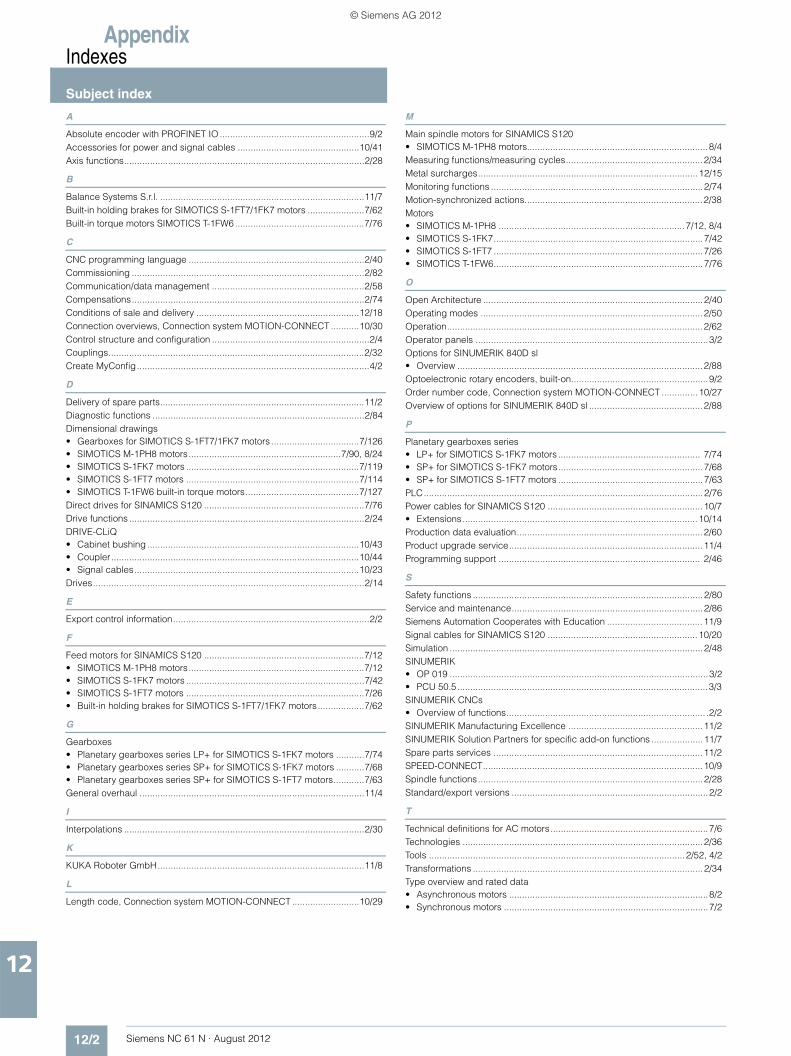
AppendixIndexes
Subject index
12/2 Siemens NC 61 N · August 2012
12
A
Absolute encoder with PROFINET IO ..........................................................9/2Accessories for power and signal cables ...............................................10/41Axis functions.............................................................................................2/28
B
Balance Systems S.r.l. ...............................................................................11/7Built-in holding brakes for SIMOTICS S-1FT7/1FK7 motors ......................7/62Built-in torque motors SIMOTICS T-1FW6..................................................7/76
C
CNC programming language ....................................................................2/40Commissioning ..........................................................................................2/82Communication/data management ...........................................................2/58Compensations..........................................................................................2/74Conditions of sale and delivery ...............................................................12/18Connection overviews, Connection system MOTION-CONNECT ...........10/30Control structure and configuration .............................................................2/4Couplings...................................................................................................2/32Create MyConfig..........................................................................................4/2
D
Delivery of spare parts...............................................................................11/2Diagnostic functions ..................................................................................2/84Dimensional drawings• Gearboxes for SIMOTICS S-1FT7/1FK7 motors ..................................7/126• SIMOTICS M-1PH8 motors...........................................................7/90, 8/24• SIMOTICS S-1FK7 motors ...................................................................7/119• SIMOTICS S-1FT7 motors ...................................................................7/114• SIMOTICS T-1FW6 built-in torque motors............................................7/127Direct drives for SINAMICS S120 ..............................................................7/76Drive functions ...........................................................................................2/24DRIVE-CLiQ• Cabinet bushing ..................................................................................10/43• Coupler................................................................................................10/44• Signal cables.......................................................................................10/23Drives.........................................................................................................2/14
E
Export control information............................................................................2/2
F
Feed motors for SINAMICS S120 ..............................................................7/12• SIMOTICS M-1PH8 motors....................................................................7/12• SIMOTICS S-1FK7 motors .....................................................................7/42• SIMOTICS S-1FT7 motors .....................................................................7/26• Built-in holding brakes for SIMOTICS S-1FT7/1FK7 motors..................7/62
G
Gearboxes• Planetary gearboxes series LP+ for SIMOTICS S-1FK7 motors ...........7/74• Planetary gearboxes series SP+ for SIMOTICS S-1FK7 motors ...........7/68• Planetary gearboxes series SP+ for SIMOTICS S-1FT7 motors............7/63General overhaul .......................................................................................11/4
I
Interpolations .............................................................................................2/30
K
KUKA Roboter GmbH................................................................................11/8
L
Length code, Connection system MOTION-CONNECT ..........................10/29
M
Main spindle motors for SINAMICS S120• SIMOTICS M-1PH8 motors......................................................................8/4Measuring functions/measuring cycles.....................................................2/34Metal surcharges.....................................................................................12/15Monitoring functions ..................................................................................2/74Motion-synchronized actions.....................................................................2/38Motors• SIMOTICS M-1PH8 ........................................................................7/12, 8/4• SIMOTICS S-1FK7.................................................................................7/42• SIMOTICS S-1FT7 .................................................................................7/26• SIMOTICS T-1FW6.................................................................................7/76
O
Open Architecture .....................................................................................2/40Operating modes ......................................................................................2/50Operation...................................................................................................2/62Operator panels ..........................................................................................3/2Options for SINUMERIK 840D sl• Overview ...............................................................................................2/88Optoelectronic rotary encoders, built-on.....................................................9/2Order number code, Connection system MOTION-CONNECT ..............10/27Overview of options for SINUMERIK 840D sl ............................................2/88
P
Planetary gearboxes series • LP+ for SIMOTICS S-1FK7 motors ....................................................... 7/74• SP+ for SIMOTICS S-1FK7 motors........................................................7/68• SP+ for SIMOTICS S-1FT7 motors ........................................................7/63PLC............................................................................................................2/76Power cables for SINAMICS S120 ............................................................10/7• Extensions...........................................................................................10/14Production data evaluation........................................................................2/60Product upgrade service...........................................................................11/4Programming support .............................................................................. 2/46
S
Safety functions ......................................................................................... 2/80Service and maintenance..........................................................................2/86Siemens Automation Cooperates with Education .....................................11/9Signal cables for SINAMICS S120 ..........................................................10/20Simulation ..................................................................................................2/48SINUMERIK• OP 019 ....................................................................................................3/2• PCU 50.5.................................................................................................3/3SINUMERIK CNCs • Overview of functions............................................................................. .2/2SINUMERIK Manufacturing Excellence ....................................................11/2SINUMERIK Solution Partners for specific add-on functions ....................11/7Spare parts services .................................................................................11/2SPEED-CONNECT.....................................................................................10/9Spindle functions.......................................................................................2/28Standard/export versions ............................................................................2/2
T
Technical definitions for AC motors.............................................................7/6Technologies .............................................................................................2/36Tools ...................................................................................................2/52, 4/2Transformations ......................................................................................... 2/34Type overview and rated data • Asynchronous motors .............................................................................8/2• Synchronous motors ...............................................................................7/2
© Siemens AG 2012

AppendixIndexes
12/3Siemens NC 61 N · August 2012
Type index
12
Numeric
1FK7...........................................................................................................7/421FK7 Compact...........................................................................................7/461FK7 Compact for Power Modules............................................................7/561FK7 High Dynamic...................................................................................7/521FK7 High Dynamic for Power Modules....................................................7/601FK7 High Inertia .......................................................................................7/541FT7 ...........................................................................................................7/261FT7 Compact core type ...........................................................................7/281FT7 High Dynamic ...................................................................................7/401FW6..........................................................................................................7/761PH8 asynchronous motors.........................................................................8/41PH8 synchronous motors.........................................................................7/121XB7322-P05 ....................................................................................7/25, 8/231XB7422-P06 ....................................................................................7/25, 8/231XB7700-P02 ....................................................................................7/25, 8/23
G
gk803 .........................................................................................................8/23gk813 .........................................................................................................8/23gk823 .........................................................................................................8/23gk826 .........................................................................................................8/23gk833 ................................................................................................7/25, 8/23gk843 ................................................................................................7/25, 8/23gk846 .........................................................................................................8/23gk863 .........................................................................................................8/23gk873 .........................................................................................................8/23gk874 .........................................................................................................7/25
L
LP+ ............................................................................................................7/74LP 050-MO1...............................................................................................7/75LP 070-MO1...............................................................................................7/75LP 090-MO1...............................................................................................7/75LP 120-MO1...............................................................................................7/75LP 155-MO1...............................................................................................7/75
O
OP 019 .........................................................................................................3/2
P
PCU 50.5......................................................................................................3/3PCU 50.5-C..................................................................................................3/6PCU 50.5-P ..................................................................................................3/6
R
RCS............................................................................................................2/86
S
SP+ ..........................................................................................7/63, 7/68, 7/74SP 060S-MF1 ....................................................................................7/64, 7/69SP 060S-MF2 .............................................................................................7/71SP 075S-MF1 ....................................................................................7/64, 7/69SP 075S-MF2 ....................................................................................7/66, 7/71SP 100S-MF1 ....................................................................................7/64, 7/69SP 100S-MF2 ....................................................................................7/66, 7/71SP 140S-MF1 ....................................................................................7/64, 7/69SP 140S-MF2 ....................................................................................7/66, 7/71SP 180S-MF1 ....................................................................................7/64, 7/69SP 180S-MF2 ....................................................................................7/66, 7/72SP 210S-MF1 ....................................................................................7/64, 7/69SP 210S-MF2 ....................................................................................7/66, 7/72SP 240S-MF2 ....................................................................................7/66, 7/72
© Siemens AG 2012

AppendixIndexes
Order number index
12/4 Siemens NC 61 N · August 2012
12
1FK701.-...
1FK7011-5AK21-1... .................................... 7/581FK7011-5AK71-1... .................................... 7/501FK7015-5AK21-1... .................................... 7/581FK7015-5AK71-1... .................................... 7/50
1FK702.-...
1FK7022-5AK21-1... .................................... 7/581FK7022-5AK71-1... .................................... 7/50
1FK703.-...
1FK7032-2AF21-1........................................ 7/561FK7032-2AK71-1... .................................... 7/481FK7033-4CF21-1........................................ 7/601FK7033-4CK71-1... .................................... 7/521FK7034-2AF21-1........................................ 7/561FK7034-2AK71-1... .................................... 7/48
1FK704.-...
1FK7040-2AK71-1... .................................... 7/481FK7042-2AC71-1... .................................... 7/461FK7042-2AF21-1........................................ 7/561FK7042-2AF71-1........................................ 7/461FK7042-2AK71-1... .................................... 7/481FK7042-3BK71-1... .................................... 7/541FK7043-4CF21-1........................................ 7/601FK7043-4CH71-1... .................................... 7/521FK7043-4CK71-1... .................................... 7/521FK7044-4CF71-1........................................ 7/521FK7044-4CH71-1... .................................... 7/52
1FK706.-...
1FK7060-2AC71-1... .................................... 7/461FK7060-2AF71-1........................................ 7/461FK7060-2AH71-1... .................................... 7/481FK7060-3BF71-1........................................ 7/541FK7061-4CF71-1........................................ 7/521FK7061-4CH71-1... .................................... 7/521FK7062-2AC71-1... .................................... 7/461FK7062-2AF71-1........................................ 7/461FK7062-2AH71-1... .................................... 7/481FK7062-3BF71-1........................................ 7/541FK7063-2AC71-1... .................................... 7/461FK7063-2AF71-1........................................ 7/461FK7063-2AH71-1... .................................... 7/481FK7064-4CC71-1... .................................... 7/521FK7064-4CF71-1........................................ 7/521FK7064-4CH71-1... .................................... 7/52
1FK708.-...
1FK7080-2AF71-1........................................ 7/461FK7080-2AH71-1... .................................... 7/481FK7081-2AC71-1... .................................... 7/461FK7081-2AF71-1........................................ 7/461FK7081-2AH71-1... .................................... 7/481FK7081-3BF71-1........................................ 7/541FK7083-2AC71-1... .................................... 7/461FK7083-2AF71-1........................................ 7/461FK7083-2AH71-1... .................................... 7/481FK7084-2AC71-1... .................................... 7/461FK7084-2AF71-1........................................ 7/461FK7084-3BC71-1... .................................... 7/541FK7084-3BF71-1........................................ 7/541FK7085-4CC71-1... .................................... 7/521FK7085-4CF71-1........................................ 7/521FK7086-4CC71-1... .................................... 7/521FK7086-4CF71-1........................................ 7/52
1FK710.-...
1FK7100-2AC71-1........................................7/461FK7100-2AF71-1... .....................................7/461FK7101-2AC71-1........................................7/461FK7101-2AF71-1... .....................................7/461FK7103-2AC71-1........................................7/461FK7103-2AF71-1... .....................................7/461FK7105-2AC71-1........................................7/461FK7105-2AF71-1... .....................................7/46
1FT703.-...
1FT7034-1AK7.-1..1 .....................................7/281FT7034-5AK7.-1... ......................................7/321FT7036-5AK7.-1... ......................................7/32
1FT704.-...
1FT7042-5AF7.-1..........................................7/301FT7042-5AK7.-1... ......................................7/321FT7044-1AF7.-1..1......................................7/281FT7044-5AF7.-1..........................................7/301FT7044-5AK7.-1... ......................................7/321FT7046-5AF7.-1..........................................7/301FT7046-5AH7.-1... ......................................7/32
1FT7062-...
1FT7062-1AF7.-1..1......................................7/281FT7062-1AK7.-1..1 .....................................7/281FT7062-5AF7.-1..........................................7/301FT7062-5AK7.-1... ......................................7/321FT7062-5WF7.- 1... .....................................7/381FT7062-5WK7.- 1... ....................................7/38
1FT7064-...
1FT7064-1AF7.-1..1......................................7/281FT7064-1AK7.-1..1 .....................................7/281FT7064-5AF7.-1..........................................7/301FT7064-5AK7.-1... ......................................7/321FT7064-5WF7.- 1... .....................................7/381FT7064-5WK7.- 1... ....................................7/38
1FT7065-...
1FT7065-7SF7.-1... .......................................7/401FT7065-7SH7.-1... ......................................7/401FT7065-7WF7.-1... ......................................7/401FT7065-7WH7.-1... .....................................7/401FT7066-... ..........................................................1FT7066-5AF7.-1..........................................7/301FT7066-5AH7.-1... ......................................7/321FT7066-5WF7.- 1... .....................................7/381FT7066-5WH7.- 1... ....................................7/38
1FT7067-...
1FT7067-7SF7.-1... .......................................7/401FT7067-7SH7.-1... ......................................7/401FT7067-7WF7.-1... ......................................7/401FT7067-7WH7.-1... .....................................7/40
1FT7068-...
1FT7068-5AF7.-1..........................................7/301FT7068-5WF7.- 1... .....................................7/38
1FT7082-...
1FT7082-1AF7.-1..1......................................7/281FT7082-5AC7.-1... ......................................7/301FT7082-5AF7.-1..........................................7/301FT7082-5AH7.-1... ......................................7/321FT7082-5WC7.- 1... ....................................7/361FT7082-5WF7.- 1... .....................................7/381FT7082-5WH7.- 1... ....................................7/38
1FT7084-...
1FT7084-1AF7.-1..1 ..................................... 7/281FT7084-1AH7.-1..1 .................................... 7/281FT7084-5AC7.-1... ..................................... 7/301FT7084-5AF7.-1... ...................................... 7/301FT7084-5AH7.-1... ..................................... 7/321FT7084-5SC7.- 1........................................ 7/341FT7084-5SF7.- 1... ..................................... 7/341FT7084-5SH7.- 1........................................ 7/341FT7084-5WC7.- 1....................................... 7/361FT7084-5WF7.- 1... .................................... 7/381FT7084-5WH7.- 1....................................... 7/38
1FT7085-...
1FT7085-7SF7.-1... ...................................... 7/401FT7085-7SH7.-1......................................... 7/401FT7085-7WF7.-1... ..................................... 7/401FT7085-7WH7.-.......................................... 7/40
1FT7086-...
1FT7086-1AF7.-1..1 ..................................... 7/281FT7086-1AH7.-1..1 .................................... 7/281FT7086-5AC7.-1... ..................................... 7/301FT7086-5AF7.-1... ...................................... 7/301FT7086-5AH7.-1... ..................................... 7/321FT7086-5SC7.- 1........................................ 7/341FT7086-5SF7.- 1... ..................................... 7/341FT7086-5SH7.- 1........................................ 7/341FT7086-5WC7.- 1....................................... 7/361FT7086-5WF7.- 1... .................................... 7/381FT7086-5WH7.- 1....................................... 7/38
1FT7087-...
1FT7087-7SF7.-1... ...................................... 7/401FT7087-7SH7.-........................................... 7/401FT7087-7WF7.-.... ...................................... 7/401FT7087-7WH7.-.......................................... 7/40
1FT7102-...
1FT7102-1AC7.-1..1 .................................... 7/281FT7102-5AB7.-1......................................... 7/301FT7102-5AC7.-1... ..................................... 7/301FT7102-5AF7.-1... ...................................... 7/301FT7102-5WB7.- 1... .................................... 7/361FT7102-5WC7.- 1....................................... 7/361FT7102-5WF7.- 1... .................................... 7/38
1FT7105-...
1FT7105-1AC7.-1..1 .................................... 7/281FT7105-5AB7.-1......................................... 7/301FT7105-5AC7.-1... ..................................... 7/301FT7105-5AF7.-1... ...................................... 7/301FT7105-5SC7.- 1........................................ 7/341FT7105-5SF7.-.... ....................................... 7/341FT7105-5WB7.- 1... .................................... 7/361FT7105-5WC7.- 1....................................... 7/361FT7105-5WF7.-.... ...................................... 7/38
1FT7108-...
1FT7108-5AB7.-1......................................... 7/301FT7108-5AC7.-1... ..................................... 7/301FT7108-5AF7.-1... ...................................... 7/301FT7108-5SC7.- 1........................................ 7/341FT7108-5SF7.-.... ....................................... 7/341FT7108-5WB7.- 1... .................................... 7/361FT7108-5WC7.-.......................................... 7/361FT7108-5WF7.-.... ...................................... 7/38
© Siemens AG 2012

AppendixIndexes
12/5Siemens NC 61 N · August 2012
Order number index
12
1FW6050-...
1FW6050-0.B03-0F.1 ................................... 7/781FW6050-0.B05-0F.1 ................................... 7/781FW6050-0.B07-0F.1 ................................... 7/781FW6050-0.B07-0K.1................................... 7/781FW6050-0.B10-0K.1................................... 7/781FW6050-0.B15-0K.1................................... 7/781FW6050-0.B15-1J.1 ................................... 7/78
1FW6060-...
1FW6060-0.B03-0F.1 ................................... 7/781FW6060-0.B05-0F.1 ................................... 7/781FW6060-0.B05-0K.1................................... 7/781FW6060-0.B07-0F.1 ................................... 7/781FW6060-0.B07-0K.1................................... 7/781FW6060-0.B10-0K.1................................... 7/781FW6060-0.B10-1J.1 ................................... 7/781FW6060-0.B15-0K.1................................... 7/781FW6060-0.B15-1J.1 ................................... 7/78
1FW6090-...
1FW6090-0.B05-0F.2 ................................... 7/801FW6090-0.B05-0K.2................................... 7/801FW6090-0.B07-0K.2................................... 7/801FW6090-0.B07-1J.2 ................................... 7/801FW6090-0.B10-0K.2................................... 7/801FW6090-0.B10-1J.2 ................................... 7/801FW6090-0.B15-1J.2 ................................... 7/801FW6090-0.B15-2J.2 ................................... 7/80
1FW6130-...
1FW6130-0.B05-0K.2................................... 7/801FW6130-0.B05-1J.2 ................................... 7/801FW6130-0.B07-0K.2................................... 7/801FW6130-0.B07-1J.2 ................................... 7/801FW6130-0.B10-1J.2 ................................... 7/801FW6130-0.B10-2J.2 ................................... 7/801FW6130-0.B15-1J.2 ................................... 7/801FW6130-0.B15-2J.2 ................................... 7/80
1FW6150-...
1FW6150-0.B05-1J.2 ................................... 7/801FW6150-0.B05-4F.2 ................................... 7/801FW6150-0.B07-2J.2 ................................... 7/801FW6150-0.B07-4F.2 ................................... 7/801FW6150-0.B10-2J.2 ................................... 7/801FW6150-0.B10-4F.2 ................................... 7/801FW6150-0.B15-2J.2 ................................... 7/801FW6150-0.B15-4F.2 ................................... 7/80
1FW6160-...
1FW6160-0.B05-1J.2 ................................... 7/821FW6160-0.B05-2J.2 ................................... 7/821FW6160-0.B05-5G.2 .................................. 7/821FW6160-0.B07-1J.2 ................................... 7/821FW6160-0.B07-2J.2 ................................... 7/821FW6160-0.B07-5G.2 .................................. 7/821FW6160-0.B07-8FB2.................................. 7/821FW6160-0.B10-1J.2 ................................... 7/821FW6160-0.B10-2J.2 ................................... 7/821FW6160-0.B10-2PB2 ................................. 7/821FW6160-0.B10-5G.2 .................................. 7/821FW6160-0.B10-8FB2.................................. 7/821FW6160-0.B15-0WB2 ................................ 7/821FW6160-0.B15-2J.2 ................................... 7/821FW6160-0.B15-2PB2 ................................. 7/821FW6160-0.B15-5G.2 .................................. 7/821FW6160-0.B15-8FB2.................................. 7/821FW6160-0.B20-0WB2 ................................ 7/82
1FW6160-0.B20-2PB2..................................7/821FW6160-0.B20-5G.2...................................7/821FW6160-0.B20-8FB2 ..................................7/821FW6160-1BA00-0AA0 ................................7/89
1FW6190-...
1FW6190-0.B05-1J.2....................................7/841FW6190-0.B05-2J.2....................................7/841FW6190-0.B05-5G.2...................................7/841FW6190-0.B07-1J.2....................................7/841FW6190-0.B07-2J.2....................................7/841FW6190-0.B07-5G.2...................................7/841FW6190-0.B07-8FB2 ..................................7/841FW6190-0.B10-1J.2....................................7/841FW6190-0.B10-2J.2....................................7/841FW6190-0.B10-2PB2..................................7/841FW6190-0.B10-5G.2...................................7/841FW6190-0.B10-8FB2 ..................................7/841FW6190-0.B15-0WB2.................................7/841FW6190-0.B15-2J.2....................................7/841FW6190-0.B15-2PB2..................................7/841FW6190-0.B15-5G.2...................................7/841FW6190-0.B15-8FB2 ..................................7/841FW6190-0.B20-0WB2.................................7/841FW6190-0.B20-2PB2..................................7/841FW6190-0.B20-5G.2...................................7/841FW6190-0.B20-8FB2 ..................................7/84
1FW6230-...
1FW6230-0.B05-1J72...................................7/861FW6230-0.B05-2J72...................................7/861FW6230-0.B05-5G72..................................7/861FW6230-0.B07-1J72...................................7/861FW6230-0.B07-2J72...................................7/861FW6230-0.B07-5G72..................................7/861FW6230-0.B07-8FB2 ..................................7/861FW6230-0.B10-2J72...................................7/861FW6230-0.B10-2PB2..................................7/861FW6230-0.B10-5G72..................................7/861FW6230-0.B10-8FB2 ..................................7/861FW6230-0.B15-0WB2.................................7/861FW6230-0.B15-2PB2..................................7/861FW6230-0.B15-4C7 2.................................7/861FW6230-0.B15-5G7 2.................................7/861FW6230-0.B15-8FB2 ..................................7/861FW6230-0.B20-0WB2.................................7/861FW6230-0.B20-2PB2..................................7/861FW6230-0.B20-5G72..................................7/861FW6230-0.B20-8FB2 ..................................7/86
1FW6290-...
1FW6290-0.B07-0LB2 ..................................7/881FW6290-0.B07-2PB2..................................7/881FW6290-0.B07-5G.2...................................7/881FW6290-0.B11-0LB2 ..................................7/881FW6290-0.B11-2PB2..................................7/881FW6290-0.B11-7A.2 ...................................7/881FW6290-0.B15-0LB2 ..................................7/881FW6290-0.B15-2PB2..................................7/881FW6290-0.B15-7A.2 ...................................7/881FW6290-0.B20-0LB2 ..................................7/881FW6290-0.B20-2PB2..................................7/881FW6290-1BA00-0AA0 ................................7/89
1PH8083-...
1PH8083-1.F..-...1...........................................8/81PH8083-1.F2.-...1 .......................................8/141PH8083-1.G..-...1 .........................................8/81PH8083-1.G2.-...1 ......................................8/14
1PH8083-1.M..-...1......................................... 8/81PH8083-1.N..-...1 ......................................... 8/81PH8083-1.N2.-...1 ...................................... 8/14
1PH8087-...
1PH8087-1.F..-...1 .......................................... 8/81PH8087-1.F2.-...1....................................... 8/141PH8087-1.G..-...1 ......................................... 8/81PH8087-1.G2.-...1 ...................................... 8/141PH8087-1.M..-...1......................................... 8/81PH8087-1.N..-...1 ......................................... 8/81PH8087-1.N2.-...1 ...................................... 8/14
1PH8101-...
1PH8101-1.F..-...1 .......................................... 8/81PH8101-1.F2.-...1....................................... 8/141PH8101-1.G2.-...1 ...................................... 8/141PH8101-1.S..-...1 ....................................... 8/10
1PH8103-...
1PH8103-1.D..-...1 ......................................... 8/81PH8103-1.F..-...1 .......................................... 8/81PH8103-1.F2.-...1....................................... 8/141PH8103-1.G..-...1 ......................................... 8/81PH8103-1.G2.-...1 ...................................... 8/141PH8103-1.M..-...1......................................... 8/81PH8103-1.M2.-...1...................................... 8/14
1PH8105-...
1PH8105-1.F..-...1 .......................................... 8/81PH8105-1.F2.-...1....................................... 8/141PH8105-1.G2.-...1 ...................................... 8/141PH8105-1.M2.-...1...................................... 8/141PH8105-1.S..-...1 ....................................... 8/10
1PH8107-...
1PH8107-1.D..-...1 ......................................... 8/81PH8107-1.F..-...1 .......................................... 8/81PH8107-1.F2.-...1....................................... 8/141PH8107-1.G..-...1 ......................................... 8/81PH8107-1.M..-...1......................................... 8/81PH8107-1.M2.-...1...................................... 8/141PH8107-1.S..-...1 ....................................... 8/10
1PH8131-...
1PH8131-1.F..-...1 .......................................... 8/81PH8131-1.F2.-...1....................................... 8/141PH8131-1.G2.-...1 ...................................... 8/141PH8131-1.S..-...1 ....................................... 8/101PH8131-2.F..-...1 ........................................ 7/141PH8131-2.F2.-...1....................................... 7/141PH8131-2.L..-...1........................................ 7/141PH8131-2.L2.-...1....................................... 7/14
1PH8133-...
1PH8133-1.D..-...1 ......................................... 8/81PH8133-1.F..-...1 .......................................... 8/81PH8133-1.F2.-...1....................................... 8/141PH8133-1.G..-...1 ......................................... 8/81PH8133-1.G2.-...1 ...................................... 8/141PH8133-2.F..-...1 ........................................ 7/141PH8133-2.F2.-...1....................................... 7/141PH8133-2.G2.-...1 ...................................... 7/141PH8133-2.L..-...1........................................ 7/14
1PH8135-...
1PH8135-1.F..-...1 .......................................... 8/81PH8135-1.F2.-...1....................................... 8/141PH8135-1.G2.-...1 ...................................... 8/141PH8135-1.S..-...1 ....................................... 8/10
© Siemens AG 2012

AppendixIndexes
Order number index
12/6 Siemens NC 61 N · August 2012
12
1PH8135-2.F..-...1 ........................................ 7/141PH8135-2.F2.-...1....................................... 7/141PH8135-2.G..-...1 ....................................... 7/141PH8135-2.G2.-...1 ...................................... 7/14
1PH8137-...
1PH8137-1.D..-...1 ......................................... 8/81PH8137-1.F..-...1 .......................................... 8/81PH8137-1.F2.-...1....................................... 8/141PH8137-1.G..-...1 ......................................... 8/81PH8137-1.S..-...1........................................ 8/101PH8137-2.F..-...1 ........................................ 7/141PH8137-2.F2.-...1....................................... 7/141PH8137-2.G2.-...1 ...................................... 7/141PH8137-2.L..-...1........................................ 7/141PH8137-2.M..-...1....................................... 7/14
1PH8138-...
1PH8138-1.F2.-...1....................................... 8/141PH8138-2.F2.-...1....................................... 7/141PH8138-2.G2.-...1 ...................................... 7/14
1PH8163-...
1PH8163-1.B..-...1 ......................................... 8/81PH8163-1.D..-...1 ......................................... 8/81PH8163-1.F..-...1 .......................................... 8/81PH8163-1.F2.-...1....................................... 8/141PH8163-1.G..-...1 ......................................... 8/81PH8163-1.G2.-...1 ...................................... 8/14
1PH8164-...
1PH8164-2.F2.-...1....................................... 7/161PH8164-2.L2.-...1....................................... 7/16
1PH8165-...
1PH8165-1.B..-...1 ......................................... 8/81PH8165-1.D..-...1 ......................................... 8/81PH8165-1.F..-...1 .......................................... 8/81PH8165-1.F2.-...1....................................... 8/141PH8165-1.G..-...1 ......................................... 8/81PH8165-1.G2.-...1 ...................................... 8/141PH8165-2.F..-...1 ........................................ 7/161PH8165-2.L..-...1........................................ 7/16
1PH8166-...
1PH8166-1.F2.-...1....................................... 8/141PH8166-1.G2.-...1 ...................................... 8/141PH8166-2.F2.-...1....................................... 7/161PH8166-2.L2.-...1....................................... 7/16
1PH8167-...
1PH8167-2.F..-...1 ........................................ 7/161PH8167-2.L..-...1........................................ 7/16
1PH8168-...
1PH8168-2.F2.-...1....................................... 7/161PH8168-2.L2.-...1....................................... 7/16
1PH8184-...
1PH8184-1.B..-...1 ....................................... 8/121PH8184-1.B2.-...1 ...................................... 8/161PH8184-1.C..-...1 ....................................... 8/121PH8184-1.C2.-...1 ...................................... 8/161PH8184-1.D..-...1 ....................................... 8/121PH8184-1.D2.-...1 ...................................... 8/161PH8184-1.F..-...1 ........................................ 8/121PH8184-1.F2.-...1....................................... 8/161PH8184-1.L..-...1........................................ 8/121PH8184-1.L2.-...1....................................... 8/161PH8184-2.C..-...1 ....................................... 7/18
1PH8184-2.C2.-...1.......................................7/201PH8184-2.D..-...1........................................7/181PH8184-2.D2.-...1.......................................7/201PH8184-2.F..-...1.........................................7/181PH8184-2.F2.-...1 .......................................7/201PH8184-2.L2.-...1 .......................................7/20
1PH8186-...
1PH8186-1.B..-...1........................................8/121PH8186-1.B2.-...1.......................................8/161PH8186-1.C..-...1........................................8/121PH8186-1.C2.-...1.......................................8/161PH8186-1.D..-...1........................................8/121PH8186-1.D2.-...1.......................................8/161PH8186-1.F..-...1.........................................8/121PH8186-1.F2.-...1 .......................................8/161PH8186-1.L..-...1 ........................................8/121PH8186-1.L2.-...1 .......................................8/161PH8186-2.C..-...1........................................7/181PH8186-2.C2.-...1.......................................7/201PH8186-2.D..-...1........................................7/181PH8186-2.D2.-...1.......................................7/201PH8186-2.F..-...1.........................................7/181PH8186-2.F2.-...1 .......................................7/201PH8186-2.L2.-...1 .......................................7/20
1PH8224-...
1PH8224-1.B..-...1........................................8/121PH8224-1.B2.-...1.......................................8/161PH8224-1.C..-...1........................................8/121PH8224-1.C2.-...1.......................................8/161PH8224-1.D..-...1........................................8/121PH8224-1.D2.-...1.......................................8/161PH8224-1.F..-...1.........................................8/121PH8224-1.F2.-...1 .......................................8/161PH8224-1.L..-...1 ........................................8/121PH8224-1.L2.-...1 .......................................8/161PH8224-2.C..-...1........................................7/181PH8224-2.C2.-...1.......................................7/201PH8224-2.D..-...1........................................7/181PH8224-2.D2.-...1.......................................7/201PH8224-2.F..-...1.........................................7/181PH8224-2.F2.-...1 .......................................7/201PH8224-2.L2.-...1 .......................................7/20
1PH8226-...
1PH8226-1.B..-...1........................................8/121PH8226-1.B2.-...1.......................................8/161PH8226-1.C..-...1........................................8/121PH8226-1.C2.-...1.......................................8/161PH8226-1.D..-...1........................................8/121PH8226-1.D2.-...1.......................................8/161PH8226-1.F..-...1.........................................8/121PH8226-1.F2.-...1 .......................................8/161PH8226-1.L..-...1 ........................................8/121PH8226-1.L2.-...1 .......................................8/161PH8226-2.C..-...1........................................7/181PH8226-2.C2.-...1.......................................7/201PH8226-2.D..-...1........................................7/181PH8226-2.D2.-...1.......................................7/201PH8226-2.F..-...1.........................................7/181PH8226-2.F2.-...1 .......................................7/201PH8226-2.L2.-...1 .......................................7/20
1PH8228-...
1PH8228-1.B..-...1........................................8/121PH8228-1.B2.-...1.......................................8/161PH8228-1.C..-...1........................................8/121PH8228-1.C2.-...1.......................................8/16
1PH8228-1.D..-...1 ....................................... 8/121PH8228-1.D2.-...1 ...................................... 8/161PH8228-1.F..-...1 ........................................ 8/121PH8228-1.F2.-...1....................................... 8/161PH8228-1.L..-...1........................................ 8/121PH8228-1.L27.-...1..................................... 8/161PH8228-2.C..-...1 ....................................... 7/181PH8228-2.C2.-...1 ...................................... 7/201PH8228-2.D..-...1 ....................................... 7/181PH8228-2.D2.-...1 ...................................... 7/201PH8228-2.F..-...1 ........................................ 7/18
1PH8284-...
1PH8284-1.B..-...1 ....................................... 8/121PH8284-1.B2.-...1 ...................................... 8/161PH8284-1.C..-...1 ....................................... 8/121PH8284-1.C2.-...1 ...................................... 8/161PH8284-1.D..-...1 ....................................... 8/121PH8284-1.D2.-...1 ...................................... 8/161PH8284-1.F..-...1 ........................................ 8/121PH8284-1.F2.-...1....................................... 8/16
1PH8286-...
1PH8286-1.B..-...1 ....................................... 8/121PH8286-1.B2.-...1 ...................................... 8/161PH8286-1.C..-...1 ....................................... 8/121PH8286-1.C2.-...1 ...................................... 8/161PH8286-1.D..-...1 ....................................... 8/121PH8286-1.D2.-...1 ...................................... 8/161PH8286-1.F..-...1 ........................................ 8/12
1PH8288-...
1PH8288-1.B..-...1 ....................................... 8/121PH8288-1.B2.-...1 ...................................... 8/161PH8288-1.C..-...1 ....................................... 8/121PH8288-1.C2.-...1 ...................................... 8/161PH8288-1.D..-...1 ....................................... 8/12
3SB3...
3SB3000-1HA20 .......................................... 2/683SB3400-0A................................................. 2/68
6AV6...
6AV6574-1AF04-4AA0................................. 2/666AV6671-3AH00-0AX0................................. 2/706AV6671-5AE01-0AX0 ................................. 2/666AV6671-5AE11-0AX0 ................................. 2/66
6BQ3...
6BQ3030-1AA00-3AD0 ............................... 2/606BQ3030-1AA10-0AD0 ............................... 2/606BQ3030-1AA20-1AC0 ............................... 2/606BQ3030-1AA30-3AD0 ............................... 2/606BQ3030-1AA70-3AD0 ............................... 2/60
6ES7...
6ES7648-0DC40-0AA0 ................................ 2/706ES7648-0DC50-0AA0 ......................... 2/70, 3/66ES7648-2AG30-0GA0................................ 2/626ES7648-2AG40-0GA0................................ 2/626ES7648-2AJ40-1KA0 .......................... 2/62, 3/66ES7648-2AJ50-1KA0 .......................... 2/62, 3/6
6FC5203-...
6FC5203-0AC01-3AA0 ................................ 2/706FC5203-0AF00-0AA1................................. 2/626FC5203-0AF01-0AA0................................. 2/626FC5203-0AF02-0AA1................................. 2/626FC5203-0AF03-0AA0................................. 2/626FC5203-0AF04-0AA0................................. 2/62
© Siemens AG 2012

AppendixIndexes
12/7Siemens NC 61 N · August 2012
Order number index
12
6FC5203-0AF04-1BA0................................. 2/626FC5203-0AF05-0AB0................................. 2/626FC5203-0AF05-1AB0................................. 2/626FC5203-0AF08-0AB2................................. 2/626FC5203-0AF08-1AB2................................. 2/626FC5203-0AF20-0AA1................................. 2/706FC5203-0AF21-0AA1................................. 2/70
6FC521.-...
6FC5210-0DF31-2AB0................................. 2/626FC5210-0DF33-2AB0................................. 2/626FC5210-0DF52-2AA0.......................... 2/62, 3/66FC5210-0DF53-2AA0.......................... 2/62, 3/66FC5211-0BA01-0AA4 ................................ 2/78
6FC5220-...
6FC5220-0AA31-2AB0 ................................ 2/106FC5220-0AA33-2AB0 ................................ 2/106FC5220-0XA31-2AB0................................... 2/86FC5220-0XA33-2AB0................................... 2/86FC5220-0YA31-2AB0................................... 2/86FC5220-0YA33-2AB0................................... 2/86FC5222-0AA00-0AA1 ....................... 2/10, 2/78
6FC5235-...
6FC5235-0AA05-1AA2 ................................ 2/70
6FC5247-...
6FC5247-0AA35-0AA0 ................................ 2/686FC5247-0AA40-0AA0 ................................ 2/706FC5247-0AF08-2AA0................................... 3/66FC5247-0AF11-0AA0.......................... 2/68, 3/26FC5247-0AF12-1AA0................................. 2/686FC5247-0AF30-0AA0.......................... 2/68, 3/2
6FC5248-...
6FC5248-0AF14-0AA0................................... 3/26FC5248-0AF20-0AA0................................. 2/626FC5248-0AF20-1AA0.......................... 2/62, 3/66FC5248-0AF20-2AA0.......................... 2/62, 3/6
6FC5250-...
6FC5250-0AY00-0AG0 ................................ 2/846FC5250-0AY00-0AG1 ................................ 2/846FC5250-0AY00-0AG2 ................................ 2/84
6FC5252-...
6FC5252-0AY00-0AG0 ................................ 2/846FC5252-0AY00-0AG1 ................................ 2/84
6FC5253-...
6FC5253-.BX10-.AF0 ..................................... 3/66FC5253-0BX10-0AF0 .......................... 2/64, 3/66FC5253-0BX10-0AG1 ................................ 2/646FC5253-0BX10-0AG2 ................................ 2/646FC5253-0BX20-0AG0 ................................ 2/406FC5253-0BX20-0AG1 ................................ 2/406FC5253-0BX20-0AG2 ................................ 2/406FC5253-0BX40-0AG1 ................................ 2/646FC5253-0BX40-0AG2 ................................ 2/646FC5253-0CX25-0AG0 ................................ 2/406FC5253-0CX25-0AG1 ................................ 2/406FC5253-0CX25-0AG2 ................................ 2/406FC5253-1CX10-1XU8 .................................. 3/6
6FC5260-...
6FC5260-0AY00-0AG0 ................................ 2/486FC5260-0AY00-0AG1 ................................ 2/486FC5260-0AY00-0AG2 ................................ 2/48
6FC5263-...
6FC5263-0PY11-0AG0.................................2/666FC5263-0PY11-0AG1.................................2/66
6FC5303-...
6FC5303-0AA00-2AA0.................................2/666FC5303-0AA01-1AA0.................................2/666FC5303-0AA02-0AA0........................2/68, 2/706FC5303-0AF13-0AA0 ..........................2/62, 3/26FC5303-0AF22-0AA1 .................................2/686FC5303-0AF22-1AA1 .................................2/686FC5303-0AF23-0AA1 .................................2/686FC5303-0AF23-1AA1 .................................2/686FC5303-0AF30-1AA0 .................................2/686FC5303-0DM13-1AA0 ................................2/706FC5303-0DT12-1AA0 .................................2/706FC5303-1AF00-0AA1 .................................2/686FC5303-1AF00-1AA1 .................................2/686FC5303-1AF00-8AA1 .................................2/686FC5303-1AF01-0AA1 .................................2/686FC5303-1AF10-0AA0 .................................2/686FC5303-1AF10-8AA0 .................................2/686FC5303-1AF20-8AA1 .................................2/68
6FC5311-...
6FC5311-0AA00-0AA0.................................2/76
6FC5312-...
6FC5312-0DA00-0AA1.................................2/626FC5312-0DA01-0AA0.................................2/686FC5312-0FA01-0AA0 ...................................2/4
6FC5313-...
6FC5313-5AG00-0AA1 .........................2/8, 2/706FC5313-6AG00-0AA0 ..................2/8, 2/70, 3/6
6FC5335-...
6FC5335-0AA00-0AA0.................................2/70
6FC5347-...
6FC5347-0AF01-1AA0 ...................................3/2
6FC5348-...
6FC5348-0AA07-0AA0...................................2/46FC5348-0AA08-0AA0.................................2/666FC5348-0AA08-1AA0.................................2/666FC5348-0AA08-2AA0.................................2/666FC5348-0AA08-4AA0.................................2/66
6FC5370-...
6FC5370-0AA00-1AA1.................................2/106FC5370-0AA00-2AA1.................................2/106FC5370-0AA00-2BA1.................................2/106FC5370-0AA00-3AA1.................................2/106FC5370-0AA00-3BA1.................................2/10
6FC5371-...
6FC5371-0AA10-0AA1...................................2/4
6FC5372-...
6FC5372-0AA00-0AA2...................................2/46FC5372-0AA01-0AA2...................................2/4
6FC5373-...
6FC5373-0AA00-0AA2...................................2/46FC5373-0AA01-0AA2...................................2/4
6FC5403-...
6FC5403-0AA20-0AA0.................................2/666FC5403-0AA20-1AA0.................................2/66
6FC5603-...
6FC5603-0AD00-0AA2 ................................ 2/686FC5611-0CA01-0AA1 ................................ 2/76
6FC5800-0AA..-...
6FC5800-0AA00-0YB0 ................................ 2/12
6FC5800-0AB..-...
6FC5800-0AB00-0YB0 ................................ 2/12
6FC5800-0AC..-...
6FC5800-0AC00-0YB0 ................................ 2/106FC5800-0AC10-0YB0 ................................ 2/106FC5800-0AC60-0YB0 ................................ 2/806FC5800-0AC70-0YB0 ................................ 2/80
6FC5800-0AD..-...
6FC5800-0AD00-0YB0 ................................ 2/106FC5800-0AD10-0YB0 ................................ 2/76
6FC5800-0AM0.-...
6FC5800-0AM00-0YB0................................ 2/426FC5800-0AM01-0YB0................................ 2/286FC5800-0AM02-0YB0................................ 2/326FC5800-0AM03-0YB0................................ 2/326FC5800-0AM04-0YB0................................ 2/406FC5800-0AM05-0YB0................................ 2/286FC5800-0AM06-0YB0................................ 2/286FC5800-0AM07-0YB0................................ 2/286FC5800-0AM08-0YB0................................ 2/36
6FC5800-0AM1.-...
6FC5800-0AM10-0YB0................................ 2/126FC5800-0AM13-0YB0................................ 2/286FC5800-0AM14-0YB0................................ 2/326FC5800-0AM15-0YB0................................ 2/306FC5800-0AM16-0YB0................................ 2/306FC5800-0AM17-0YB0................................ 2/306FC5800-0AM18-0YB0................................ 2/30
6FC5800-0AM2.-...
6FC5800-0AM20-0YB0................................ 2/326FC5800-0AM21-0YB0................................ 2/306FC5800-0AM22-0YB0................................ 2/326FC5800-0AM23-0YB0................................ 2/326FC5800-0AM24-0YB0................................ 2/306FC5800-0AM25-0YB0................................ 2/346FC5800-0AM26-0YB0................................ 2/366FC5800-0AM27-0YB0................................ 2/346FC5800-0AM28-0YB0................................ 2/34
6FC5800-0AM3.-...
6FC5800-0AM30-0YB0................................ 2/366FC5800-0AM31-0YB0................................ 2/346FC5800-0AM32-0YB0................................ 2/346FC5800-0AM33-0YB0................................ 2/366FC5800-0AM34-0YB0................................ 2/366FC5800-0AM35-0YB0................................ 2/366FC5800-0AM36-0YB0................................ 2/386FC5800-0AM37-0YB0................................ 2/386FC5800-0AM38-0YB0................................ 2/38
6FC5800-0AM4.-...
6FC5800-0AM40-0YB0................................ 2/386FC5800-0AM41-0YB0................................ 2/386FC5800-0AM42-0YB0................................ 2/386FC5800-0AM43-0YB0................................ 2/386FC5800-0AM44-0YB0................................ 2/346FC5800-0AM48-0YB0................................ 2/52
© Siemens AG 2012

AppendixIndexes
Order number index
12/8 Siemens NC 61 N · August 2012
12
6FC5800-0AM5.-...
6FC5800-0AM50-0YB0 ................................ 2/546FC5800-0AM51-0YB0 ................................ 2/346FC5800-0AM52-0YB0 ................................ 2/746FC5800-0AM53-0YB0 ................................ 2/746FC5800-0AM54-0YB0 ................................ 2/746FC5800-0AM55-0YB0 ................................ 2/746FC5800-0AM57-0YB0 ................................ 2/74
6FC5800-0AM6.-...
6FC5800-0AM61-0YB0 ................................ 2/746FC5800-0AM62-0YB0 ................................ 2/746FC5800-0AM63-0YB0 ................................ 2/806FC5800-0AM64-0YB0 ................................ 2/806FC5800-0AM65-0YB0 ................................ 2/38
6FC5800-0AM7.-...
6FC5800-0AM72-0YB0 ................................ 2/326FC5800-0AM73-0YB0 ................................ 2/326FC5800-0AM74-0YB0 ................................ 2/326FC5800-0AM75-0YB0 ................................ 2/326FC5800-0AM76-0YB0 ................................ 2/36
6FC5800-0AM8.-...
6FC5800-0AM81-0YB0 ................................ 2/326FC5800-0AM88-0YB0 ................................ 2/52
6FC5800-0AN..-...
6FC5800-0AN00-0YB0 ................................ 2/726FC5800-0AN04-0YB0 ................................ 2/306FC5800-0AN05-0YB0 ................................ 2/366FC5800-0AN06-0YB0 ................................ 2/746FC5800-0AN07-0YB0 ................................ 2/586FC5800-0AN11-0YB0 ................................ 2/766FC5800-0AN12-0YB0 ................................ 2/746FC5800-0AN13-0YB0 ................................ 2/746FC5800-0AN15-0YB0 ................................ 2/746FC5800-0AN16-0YB0 ................................ 2/766FC5800-0AN17-0YB0 ................................ 2/766FC5800-0AN31-0YB0 ................................ 2/766FC5800-0AN34-0YB0 ................................ 2/346FC5800-0AN36-0YB0 ................................ 2/346FC5800-0AN46-0YB0 ................................ 2/766FC5800-0AN51-0YB0 ................................ 2/366FC5800-0AN54-0YB0 ................................ 2/346FC5800-0AN61-0YB0 ................................ 2/586FC5800-0AN76-0YB0 ................................ 2/36
6FC5800-0AP0.-...
6FC5800-0AP00-0YB0................................. 2/666FC5800-0AP01-0YB0........................ 2/50, 2/586FC5800-0AP02-0YB0................................. 2/406FC5800-0AP03-0YB0................................. 2/406FC5800-0AP04-0YB0................................. 2/466FC5800-0AP05-0YB0................................. 2/46
6FC5800-0AP1.-...
6FC5800-0AP10-0YB0................................. 2/366FC5800-0AP11-0YB0................................. 2/466FC5800-0AP12-0YB0............... 2/12, 2/50, 2/586FC5800-0AP13-0YB0................................. 2/466FC5800-0AP14-0YB0................................. 2/466FC5800-0AP15-0YB0................................. 2/466FC5800-0AP17-0YB0................................. 2/466FC5800-0AP18-0YB0................................. 2/34
6FC5800-0AP2.-...
6FC5800-0AP20-0YB0................................. 2/486FC5800-0AP21-0YB0................................. 2/48
6FC5800-0AP22-0YB0 .................................2/486FC5800-0AP23-0YB0 .................................2/486FC5800-0AP24-0YB0 .................................2/486FC5800-0AP25-0YB0 .................................2/486FC5800-0AP28-0YB0 .................................2/34
6FC5800-0AP3.-...
6FC5800-0AP30-0YB0 .................................2/866FC5800-0AP32-0YB0 .................................2/866FC5800-0AP33-0YB0 .................................2/566FC5800-0AP34-0YB0 .................................2/566FC5800-0AP35-0YB0 .................................2/566FC5800-0AP36-0YB0 .................................2/566FC5800-0AP37-0YB0 .................................2/566FC5800-0AP38-0YB0 .................................2/56
6FC5800-0AP4.-...
6FC5800-0AP40-0YB0 .................................2/586FC5800-0AP41-0YB0 .................................2/606FC5800-0AP42-0YB0 .................................2/606FC5800-0AP43-0YB0 .................................2/606FC5800-0AP46-0YB0 .................................2/866FC5800-0AP47-0YB0 .................................2/666FC5800-0AP48-0YB0 .................................2/60
6FC5800-0AP5.-...
6FC5800-0AP50-0YB0 .................................2/606FC5800-0AP51-0YB0 .................................2/566FC5800-0AP53-0YB0 .................................2/686FC5800-0AP54-0YB0 .................................2/46
6FC5800-0AP6.-...
6FC5800-0AP60-0YB0 .................................2/406FC5800-0AP64-0YB0 .................................2/406FC5800-0AP66-0YB0 .................................2/40
6FC5800-0AS..-...
6FC5800-0AS01-0YB0 .................................2/366FC5800-0AS07-0YB0 .................................2/306FC5800-0AS08-0YB0 ........................2/54, 2/746FC5800-0AS16-0YB0 .................................2/306FC5800-0AS31-0YB0 .................................2/366FC5800-0AS32-0YB0 .................................2/366FC5800-0AS33-0YB0 .................................2/366FC5800-0AS40-0YB0 .................................2/36
6FC5820-...
6FC5820-1XP00-0YB0 .................................2/106FC5820-1YP00-0YB0 .................................2/106FC5820-3XP00-0YB0 .................................2/106FC5820-3XP00-0YL8....................................2/86FC5820-3YP00-0YB0 .................................2/106FC5820-3YP00-0YL8....................................2/8
6FC5840-...
6FC5840-1XF00-0YB0....................................2/46FC5840-1YF00-0YB0....................................2/46FC5840-3XF00-0YB0....................................2/46FC5840-3XP00-0YL8....................................2/46FC5840-3YF00-0YB0....................................2/46FC5840-3YP00-0YL8....................................2/4
6FC5841-...
6FC5841-1XF00-0YB0....................................2/66FC5841-1YF00-0YB0....................................2/66FC5841-3XF00-0YB0....................................2/66FC5841-3XP00-0YL8....................................2/66FC5841-3YF00-0YB0....................................2/66FC5841-3YP00-0YL8....................................2/6
6FC5842-...
6FC5842-1XF00-0YB0 ................................... 2/66FC5842-1YF00-0YB0 ................................... 2/66FC5842-3XF00-0YB0 ................................... 2/66FC5842-3XP00-0YL8 ................................... 2/66FC5842-3YF00-0YB0 ................................... 2/66FC5842-3YP00-0YL8 ................................... 2/6
6FC5850-...
6FC5850-1XF00-0YB0 ................................... 2/86FC5850-1YF00-0YB0 ................................... 2/86FC5850-3XF00-0YB0 ................................... 2/86FC5850-3XP00-0YL8 ................................... 2/86FC5850-3YF00-0YB0 ................................... 2/86FC5850-3YP00-0YL8 ................................... 2/8
6FC5860-...
6FC5860-1YC00-0YA0................................. 2/646FC5860-1YF..-.YA0....................................... 3/66FC5860-1YF00-0YA0 .......................... 2/64, 3/66FC5860-1YF00-0YB0 ................................. 2/646FC5860-1YP00-0YL8 ................................. 2/646FC5860-2YC00-0YA0................................. 2/646FC5860-2YF00-0YB0 ................................. 2/646FC5860-2YP00-0YL8 ................................. 2/646FC5860-7YC00-0YA0................................. 2/86
6FC5861-...
6FC5861-1YC00-0YA0................................. 2/406FC5861-1YP00-0YB0................................. 2/406FC5861-1YP00-0YL8 ................................. 2/40
6FC5862-...
6FC5862-2YC00-0YA0................................. 2/846FC5862-2YC41-0YA0................................... 4/2
6FC5863-...
6FC5863-0YP00-0YB8................................. 2/406FC5863-1YP00-0YB8................................. 2/40
6FC5867-...
6FC5867-3YC00-0YA8................................. 2/66
6FC6000-0...
6FC6000-0AC00-0AA8 ................................ 2/586FC6000-0AC00-0AT7................................. 2/586FC6000-0BC00-0AA0 ................................ 2/586FC6000-0BF00-0AB0................................. 2/586FC6000-0CC00-0AA0................................ 2/586FC6000-0CF00-0AB0 ................................ 2/586FC6000-0DF00-0AB0 ................................ 2/606FC6000-0FF00-0AB0 ................................. 2/606FC6000-0GF00-0AB0 ................................ 2/606FC6000-0HF00-0AB0 ................................ 2/606FC6000-0KF00-0AB0................................. 2/60
6FC6000-1...
6FC6000-1AC00-0AA8 ................................ 2/866FC6000-1AC00-0AT7................................. 2/866FC6000-1BC00-0AA0 ................................ 2/866FC6000-1BF00-0AB0................................. 2/866FC6000-1DF00-0AB0 ................................ 2/86
6FC6000-2...
6FC6000-2AC00-0AA8 ................................ 2/566FC6000-2BC00-0AA0 ................................ 2/566FC6000-2BF00-0AB0................................. 2/566FC6000-2EC00-0AA8 ................................ 2/566FC6000-2FC00-0AA8 ................................ 2/566FC6000-2GC00-0AA8................................ 2/56
© Siemens AG 2012

AppendixIndexes
12/9Siemens NC 61 N · August 2012
Order number index
12
6FC6000-2HC00-0AA0 ................................ 2/566FC6000-2HF00-0AB0................................. 2/566FC6000-2JC00-0AA8................................. 2/566FC6000-2KC00-0AA8 ................................ 2/56
6FC6000-3...
6FC6000-3AC00-0AA8 ................................ 2/606FC6000-3AC00-0AT7................................. 2/606FC6000-3BC00-0AA0 ................................ 2/606FC6000-3BF00-0AB0................................. 2/606FC6000-6DA51-0AA0 ................................ 2/846FC6000-6DC00-0BA0 ................................ 2/866FC6000-6DC80-0BA0 ................................ 2/866FC6000-6DF00-0BB0................................. 2/866FC6000-6DF88-8BB0................................. 2/866FC6000-7AC00-0AA8 ................................ 2/60
6FC6001-...
6FC6001-0EE00-0AF8 ................................. 2/866FC6001-0EE00-0CA1................................. 2/866FC6001-0EE00-0DS0................................. 2/866FC6001-0EE00-0KP0 ................................. 2/866FC6001-0EE00-0MB0 ................................ 2/86
6FC93..-...
6FC9320-5DB01 .......................................... 2/706FC9320-5DC01 .......................................... 2/706FC9320-5DE02 .......................................... 2/706FC9320-5DF01........................................... 2/706FC9320-5DH01 .......................................... 2/706FC9320-5DM00.......................................... 2/706FC9341-1AQ .............................................. 2/70
6FX.002-2...
6FX.002-2AD04-.... .................................... 10/256FX.002-2AH00-.... .................................... 10/266FX.002-2AH04-.... .................................... 10/266FX.002-2AH11-.... .................................... 10/266FX.002-2CA20-.... .................................... 10/266FX.002-2CA31-…..................................... 10/266FX.002-2CA34-.... .................................... 10/266FX.002-2CB54-.... .................................... 10/256FX.002-2CC11-.... .................................... 10/256FX.002-2CD24-.... .................................... 10/266FX.002-2CF02-......................................... 10/256FX.002-2CF04-......................................... 10/256FX.002-2CF20-......................................... 10/256FX.002-2CG00-.... .................................... 10/266FX.002-2CH00-.... .................................... 10/256FX.002-2CN20-.... .................................... 10/256FX.002-2CQ31-…. ................................... 10/256FX.002-2CQ34-…. ................................... 10/256FX.002-2CR00-.... .................................... 10/266FX.002-2DC30-1AD0 ............................... 10/246FX.002-2DC30-1AG0 ............................... 10/246FX.002-2DC30-1BF0................................ 10/246FX.002-2DC30-1DA0 ............................... 10/246FX.002-2DC34-1AD0 ............................... 10/246FX.002-2DC34-1AG0 ............................... 10/246FX.002-2EN20-......................................... 10/256FX.002-2EQ10-.... .................................... 10/256FX.002-2EQ14-.... .................................... 10/256FX.002-2EQ20-.... .................................... 10/256FX.002-2EQ31-.... .................................... 10/256FX.002-2EQ34-.... .................................... 10/256FX.002-2FN20-......................................... 10/25
6FX.002-5...
6FX.002-5.A05-.... ......................................10/146FX.002-5.A15-.... ......................................10/146FX.002-5.A28-.... ......................................10/146FX.002-5.A38-.... ......................................10/146FX.002-5.A48-.... ......................................10/146FX.002-5.A58-.... ......................................10/146FX.002-5.A68-.... ......................................10/146FX.002-5.N05-.... ......................................10/146FX.002-5.Q15-.... ......................................10/146FX.002-5.Q28-.... ......................................10/146FX.002-5.Q38-.... ......................................10/146FX.002-5.Q48-.... ......................................10/146FX.002-5.Q58-.... ......................................10/146FX.002-5.Q68-.... ......................................10/146FX.002-5.X18-...........................................10/146FX.002-5.X28-...........................................10/14
6FX.002-5C...
6FX.002-5CG01-.... ....................................10/136FX.002-5CG10-.... ....................................10/106FX.002-5CG11-.... ....................................10/136FX.002-5CG12-.... ....................................10/106FX.002-5CG13-.... ....................................10/136FX.002-5CG21-.... ....................................10/136FX.002-5CG22-.... ....................................10/106FX.002-5CG23-.... ....................................10/136FX.002-5CG31-.... ....................................10/136FX.002-5CG32-.... ....................................10/106FX.002-5CG41-.... ....................................10/136FX.002-5CG42-.... ....................................10/106FX.002-5CG51-.... ....................................10/136FX.002-5CG52-.... ....................................10/106FX.002-5CG61-.... ....................................10/136FX.002-5CG62-.... ....................................10/106FX.002-5CN01-...........................................10/96FX.002-5CN11-...........................................10/96FX.002-5CN21-...........................................10/96FX.002-5CN31-...........................................10/96FX.002-5CN41-...........................................10/96FX.002-5CN51-...........................................10/96FX.002-5CN54-...........................................10/96FX.002-5CN61-...........................................10/96FX.002-5CN64-...........................................10/96FX.002-5CS01-.... .....................................10/116FX.002-5CS11-.... .....................................10/116FX.002-5CS13-.... .....................................10/116FX.002-5CS14-.... .....................................10/116FX.002-5CS21-.... .....................................10/116FX.002-5CS23-.... .....................................10/116FX.002-5CS31-.... .....................................10/116FX.002-5CS41-.... .....................................10/116FX.002-5CS51-.... .....................................10/116FX.002-5CS54-.... .....................................10/116FX.002-5CS61-.... .....................................10/116FX.002-5CS64-.... .....................................10/11
6FX.002-5D...
6FX.002-5DG01-.... ....................................10/136FX.002-5DG10-.... ....................................10/106FX.002-5DG11-.... ....................................10/136FX.002-5DG12-.... ....................................10/106FX.002-5DG13-.... ....................................10/136FX.002-5DG21-.... ....................................10/136FX.002-5DG22-.... ....................................10/106FX.002-5DG23-.... ....................................10/126FX.002-5DG23-.... ....................................10/136FX.002-5DG31-.... ....................................10/13
6FX.002-5DG32-.... .................................... 10/106FX.002-5DG33-.... ......................... 10/12, 10/136FX.002-5DG41-.... .................................... 10/136FX.002-5DG42-.... .................................... 10/106FX.002-5DG43-.... ......................... 10/12, 10/136FX.002-5DG51-.... .................................... 10/136FX.002-5DG52-.... .................................... 10/106FX.002-5DG53-.... ......................... 10/12, 10/136FX.002-5DG61-.... .................................... 10/136FX.002-5DG62-.... .................................... 10/106FX.002-5DN01-.... ...................................... 10/96FX.002-5DN11-.... ...................................... 10/96FX.002-5DN20-.... ...................................... 10/96FX.002-5DN21-.... ...................................... 10/96FX.002-5DN30-.... .................................... 10/106FX.002-5DN31-.... ...................................... 10/96FX.002-5DN41-.... ...................................... 10/96FX.002-5DN51-.... ...................................... 10/96FX.002-5DN54-.... ...................................... 10/96FX.002-5DN61-.... ...................................... 10/96FX.002-5DN64-.... ...................................... 10/96FX.002-5DS01-.... .................................... 10/126FX.002-5DS11-.... .................................... 10/126FX.002-5DS13-.... .................................... 10/126FX.002-5DS14-.... .................................... 10/126FX.002-5DS21-.... .................................... 10/126FX.002-5DS23-.... .................................... 10/126FX.002-5DS31-.... .................................... 10/126FX.002-5DS41-.... .................................... 10/126FX.002-5DS51-.... .................................... 10/126FX.002-5DS54-.... .................................... 10/126FX.002-5DS61-.... .................................... 10/126FX.002-5DS64-.... .................................... 10/126FX.002-5DX38-.... .................................... 10/146FX.002-5DX48-.... .................................... 10/146FX.002-5DX58-.... .................................... 10/14
6FX.002-5M...
6FX.002-5ME05-.... .................................... 10/14
6FX.008-1BA...
6FX.008-1BA11-.... ..... 10/9, 10/10, 10/12, 10/136FX.008-1BA21-.... ..... 10/9, 10/10, 10/12, 10/136FX.008-1BA25-.... ......................... 10/12, 10/136FX.008-1BA31-.... ..... 10/9, 10/10, 10/12, 10/136FX.008-1BA35-.... ......................... 10/12, 10/136FX.008-1BA41-.... ..... 10/9, 10/10, 10/12, 10/136FX.008-1BA50-.... ......................... 10/12, 10/136FX.008-1BA51-.... ..... 10/9, 10/10, 10/12, 10/136FX.008-1BA61-.... ......................... 10/12, 10/13
6FX.008-1BB...
6FX.008-1BB11-.... ..... 10/9, 10/10, 10/11, 10/136FX.008-1BB21-.... ..... 10/9, 10/10, 10/11, 10/136FX.008-1BB31-.... ..... 10/9, 10/10, 10/11, 10/136FX.008-1BB41-.... ..... 10/9, 10/10, 10/11, 10/136FX.008-1BB51-.... ..... 10/9, 10/10, 10/11, 10/136FX.008-1BB61-.... .................................... 10/11
6FX2001-...
6FX2001-5FN.. ............................................... 9/36FX2001-5QN.. .............................................. 9/36FX2001-5WN................................................ 9/3
6FX2002-...
6FX2002-1DC00-.... ................................... 10/236FX2002-1DC20-.... ................................... 10/23
© Siemens AG 2012

AppendixIndexes
Order number index
12/10 Siemens NC 61 N · August 2012
12
6FX2003-...
6FX2003-0DT67 ......................................... 10/436FX2003-0LA00 ................................ 7/89, 10/416FX2003-0LA10 ................................ 7/89, 10/416FX2003-0SU07................................ 7/89, 10/416FX2003-7AX00 ......................................... 10/426FX2003-7BX00 ......................................... 10/426FX2003-7CX00......................................... 10/426FX2003-7DX00......................................... 10/426FX2003-7FA00 ......................................... 10/426FX2003-7FX00 ......................................... 10/426FX2003-7GX00......................................... 10/426FX2003-7HX00......................................... 10/42
6FX2006-...
6FX2006-1BA02.................................. 2/10, 2/706FX2006-1BA02........................................... 2/786FX2006-1BG03 .......................................... 2/686FX2006-1BH01........................................... 2/686FX2007-1AD03........................................... 2/686FX2007-1AD13........................................... 2/686FX2007-1AE04 ........................................... 2/686FX2007-1AE14 ........................................... 2/68
6FX5002-2...
6FX5002-2CA12-.... ................................... 10/266FX5002-2CA24-.... ................................... 10/266FX5002-2CF24-........................................ 10/256FX5002-2DC00-.... ................................... 10/246FX5002-2DC10-.... ................................... 10/246FX5002-2DC20-.... ................................... 10/246FX5002-2EQ24-.... ................................... 10/256FX5002-5CR72-.... ................................... 10/166FX5002-5CR73-.... ........................ 10/15, 10/166FX5002-5CR83-.... ........................ 10/15, 10/166FX5002-5CS02-........................................ 10/116FX5002-5CS12-........................................ 10/116FX5002-5CS42-........................................ 10/116FX5002-5CS52-........................................ 10/116FX5002-5CS62-........................................ 10/116FX5002-5DA20-.... ................................... 10/126FX5002-5DA30-.... ................................... 10/13
6FX5008-1B...
6FX5008-1BA11-............................. 10/12, 10/136FX5008-1BB21-........................................ 10/166FX5008-1BB25-............................. 10/15, 10/166FX5008-1BB31-........................................ 10/166FX5008-1BB35-............................. 10/15, 10/166FX5008-1BB50-............................. 10/15, 10/166FX5008-1BB51-........................................ 10/166FX5008-1BB61-.................. 10/13, 10/15, 10/166FX5008-1BB70-............................. 10/15, 10/16
6FX7002-2...
6FX7002-2SL01-.... .................................... 10/256FX7002-2SL02-.... .................................... 10/256FX7002-2SL10-.... ........................... 7/89, 10/25
6FX7002-5...
6FX7002-5LM02-.... ................................... 10/176FX7002-5LM32-.... ................................... 10/176FX7002-5LM42-.... ................................... 10/176FX7002-5LM62-.... ................................... 10/176FX7002-5LM72-.... ................................... 10/176FX7002-5LM82-.... ................................... 10/17
6FX8002-2...
6FX8002-2AD04-.... ....................................10/256FX8002-2CA80-.... ....................................10/266FX8002-2CB54-.... ....................................10/266FX8002-2CN24-........................................10/256FX8002-2DC00-........................................10/246FX8002-2DC10-........................................10/246FX8002-2DC20-........................................10/246FX8002-2EN24-.... ....................................10/256FX8002-2FN24- ........................................ 10/25
6FX8002-5...
6FX8002-5CA15-.... .........................10/17, 10/196FX8002-5CA48-.... .........................10/17, 10/196FX8002-5CA58-.... .........................10/17, 10/196FX8002-5CA68-.... .........................10/17, 10/196FX8002-5CN01-........................................10/186FX8002-5CN05-........................................10/186FX8002-5CN11-........................................10/186FX8002-5CN41-........................................10/186FX8002-5CN64-........................................10/186FX8002-5CP10-.... ....................................10/156FX8002-5CP11-.... ....................................10/156FX8002-5CP20-.... ....................................10/156FX8002-5CP21-.... ....................................10/156FX8002-5CP41-.... ....................................10/156FX8002-5CP42-.... ....................................10/156FX8002-5CP43-.... ....................................10/156FX8002-5CQ15-.... ...................................10/186FX8002-5CR10-.... ....................................10/166FX8002-5CR11-.... ....................................10/166FX8002-5CR20-.... ....................................10/166FX8002-5CR21-.... ....................................10/166FX8002-5CR41-.... .........................10/15, 10/166FX8002-5CR42-.... .........................10/15, 10/166FX8002-5CR43-.... .........................10/15, 10/166FX8002-5CR52-.... .........................10/15, 10/166FX8002-5CR53-.... .........................10/15, 10/166FX8002-5CS11-.... .........................10/17, 10/196FX8002-5CS24-.... ..............10/11, 10/17, 10/196FX8002-5CS41-.... .........................10/17, 10/196FX8002-5CS54-.... .........................10/17, 10/196FX8002-5CS64-.... .........................10/17, 10/196FX8002-5DQ48-.... ...................................10/186FX8002-5DQ68-.... ...................................10/186FX8002-5YW12-.... ........................10/17, 10/19
6FX8008-1B...-....
6FX8008-1BA25-.... .........................10/15, 10/166FX8008-1BA35-.... .........................10/15, 10/166FX8008-1BA50-.... .........................10/15, 10/166FX8008-1BB11-.... ....................................10/186FX8008-1BB21-.... .........................10/15, 10/16 .............................................10/17, 10/18, 10/196FX8008-1BB31-.... .........................10/15, 10/16 .............................................10/17, 10/18, 10/196FX8008-1BB41-.... .........................10/17, 10/196FX8008-1BB51-.... .........................10/15, 10/16 .............................................10/17, 10/18, 10/196FX8008-1BB61-.... .........................10/15, 10/16 ........................................................10/17, 10/19
6GK1901-...
6GK1901-0DB20-6AA0 ..................................9/36GK1901-1BB30-0AA0 ..................................9/3
6GK5...
6GK5005-0BA00-1AA3................................ 2/626GK5005-0BA00-1AB2................................ 2/626GK5108-0BA00-2AA3................................ 2/626GK5208-0BA10-2AA3................................ 2/626GK5208-0HA00-2AA6 ............................... 2/62
6SL3040-...
6SL3040-0NB00-0AA0 .................................. 2/46SL3040-0NC00-0AA0 .................................. 2/4
6SL3054-...
6SL3054-0AA00-1AA0................................. 2/146SL3054-0AA01-1AA0................................. 2/14
6SL3060-...
6SL3060-4AA10-0AA0............................... 10/236SL3060-4AA50-0AA0............................... 10/236SL3060-4AB00-0AA0............................... 10/236SL3060-4AD00-0AA0 .............................. 10/236SL3060-4AF00-0AA0 ............................... 10/236SL3060-4AF10-0AA0 ............................... 10/236SL3060-4AH00-0AA0 .............................. 10/236SL3060-4AJ20-0AA0 ............................... 10/236SL3060-4AK00-0AA0............................... 10/236SL3060-4AM00-0AA0 .............................. 10/236SL3060-4AP00-0AA0............................... 10/236SL3060-4AU00-0AA0 .............................. 10/236SL3060-4AW00-0AA0 .............................. 10/236SL3066-2DA00-0AA0 .............................. 10/436SL3066-2DA00-0AB0 .............................. 10/44
6SL3072-...
6SL3072-0AA00-0AG0 ................................ 2/84
6SL3162-...
6SL3162-2MA00-0AA0 .............................. 10/41
6SL32...
6SL3210-1SB10-9AA0................................. 2/206SL3210-1SB10-9UA0................................. 2/206SL3210-1SB12-3AA0................................. 2/206SL3210-1SB12-3UA0................................. 2/206SL3210-1SB13-9AA0................................. 2/206SL3210-1SB13-9UA0................................. 2/206SL3210-1SE11-3AA0 ................................. 2/206SL3210-1SE11-3UA0................................. 2/206SL3210-1SE11-7AA0 ................................. 2/206SL3210-1SE11-7UA0................................. 2/206SL3210-1SE12-2AA0 ................................. 2/206SL3210-1SE12-2UA0................................. 2/206SL3210-1SE13-1AA0 ................................. 2/206SL3210-1SE13-1UA0................................. 2/206SL3210-1SE14-1AA0 ................................. 2/206SL3210-1SE14-1UA0................................. 2/206SL3210-1SE15-9AA0 ................................. 2/206SL3210-1SE16-0UA0................................. 2/206SL3210-1SE17-7AA0 ................................. 2/206SL3210-1SE17-7UA0................................. 2/206SL3210-1SE21-0AA0 ................................. 2/206SL3210-1SE21-0UA0................................. 2/206SL3210-1SE21-8AA0 ................................. 2/206SL3210-1SE21-8UA0................................. 2/206SL3210-1SE22-5AA0 ................................. 2/206SL3210-1SE22-5UA0................................. 2/206SL3210-1SE23-2AA0 ................................. 2/206SL3210-1SE23-2UA0................................. 2/206SL3210-1SE23-8AA0 ................................. 2/206SL3210-1SE23-8UA0................................. 2/20
© Siemens AG 2012

AppendixIndexes
12/11Siemens NC 61 N · August 2012
Order number indexIndex of order codes
12
6SL3210-1SE24-5AA0 ................................. 2/206SL3210-1SE24-5UA0 ................................. 2/206SL3210-1SE26-0AA0 ................................. 2/206SL3210-1SE26-0UA0 ................................. 2/206SL3210-1SE27-5AA0 ................................. 2/206SL3210-1SE27-5UA0 ................................. 2/206SL3210-1SE29-0AA0 ................................. 2/206SL3210-1SE29-0UA0 ................................. 2/206SL3210-1SE31-0UA0 ................................. 2/206SL3210-1SE31-1AA0 ................................. 2/206SL3210-1SE31-1UA0 ................................. 2/206SL3210-1SE31-5AA0 ................................. 2/206SL3210-1SE31-5UA0 ................................. 2/206SL3210-1SE31-8AA0 ................................. 2/206SL3210-1SE31-8UA0 ................................. 2/206SL3310-1TE32-1AA3 ................................. 2/206SL3310-1TE32-6AA3 ................................. 2/206SL3310-1TE33-1AA3 ................................. 2/206SL3310-1TE33-8AA3 ................................. 2/206SL3310-1TE35-0AA3 ................................. 2/20
6XV18...
6XV1801-5DH20 ............................................ 9/36XV1801-5DH30 ............................................ 9/36XV1801-5DH50 ............................................ 9/36XV1801-5DN10 ............................................ 9/36XV1801-5DN15 ............................................ 9/36XV1840-3AH10 ............................................ 9/36XV1871-5TH20............................................. 9/36XV1871-5TH30............................................. 9/36XV1871-5TH50............................................. 9/36XV1871-5TN10............................................. 9/36XV1871-5TN15............................................. 9/3
A
A01 ... A26....................................................2/12A12 ......................................................7/24, 8/21A25 ......................................................7/24, 8/21
B
B01 ... B26....................................................2/12
C
C01 ... C09 ...................................................2/10C11 ... C19 ...................................................2/10C61............................................................... 2/80C62............................................................... 2/80C71 ... C78 ...................................................2/80
D
D01 ... D06 ...................................................2/10D11 ... D12 ...................................................2/76D11 ... D18 ...................................................2/76
G
G00............................................................... 8/21G02............................................................... 8/21G14......................................................7/24, 8/21
J
J02.......................................................7/64, 7/69J03.......................................................7/64, 7/69J05.......................................................7/64, 7/69J09.......................................................7/64, 7/69J12..............................................7/66, 7/71, 7/72J13..............................................7/66, 7/71, 7/72J15..............................................7/66, 7/71, 7/72J16..............................................7/66, 7/71, 7/72J17..............................................7/66, 7/71, 7/72J22.......................................................7/64, 7/69J23.......................................................7/64, 7/69J25.......................................................7/64, 7/69J29.......................................................7/64, 7/69J32..............................................7/66, 7/71, 7/72J33..............................................7/66, 7/71, 7/72J35..............................................7/66, 7/71, 7/72J36..............................................7/66, 7/71, 7/72J37..............................................7/66, 7/71, 7/72
K
K08 ......................................................7/24, 8/21K09 ......................................................7/24, 8/21K10 ......................................................7/24, 8/21K16 ............................................................... 8/21K18 ......................................................7/24, 8/21K23 ....................................7/24, 7/27, 7/44, 8/22K24 ....................................7/24, 7/27, 7/44, 8/22K40 ......................................................7/24, 8/21K45 ............................................................... 8/21K69 ............................................................... 8/21K70 ............................................................... 8/21K71 ............................................................... 8/21K80 ............................................................... 8/21K83 ......................................................7/24, 8/22K84 ......................................................7/24, 8/22K85 ......................................................7/24, 8/22K90 ......................................................7/24, 8/22
L
L00 ......................................................7/24, 8/22L27 ......................................................7/24, 8/22L74 ......................................................7/24, 8/22
M
M00.............................................................. 2/42M01.............................................................. 2/28M02.............................................................. 2/32M03.............................................................. 2/32M04.............................................................. 2/40M05.............................................................. 2/28M06.............................................................. 2/28M07.............................................................. 2/28M08.............................................................. 2/36M10.............................................................. 2/12M13.............................................................. 2/28M14.............................................................. 2/32M15.............................................................. 2/30M16.............................................................. 2/30M17.............................................................. 2/30M18.............................................................. 2/30M20.............................................................. 2/32M21.............................................................. 2/30M22.............................................................. 2/32M23.............................................................. 2/32M24.............................................................. 2/30M25.............................................................. 2/34M26.............................................................. 2/36M27.............................................................. 2/34M28.............................................................. 2/34M30.............................................................. 2/36M31.............................................................. 2/34M32.............................................................. 2/34M33.............................................................. 2/36M34.............................................................. 2/36M35.............................................................. 2/36M36.............................................................. 2/38M37.............................................................. 2/38M38.............................................................. 2/38M40.............................................................. 2/38M41.............................................................. 2/38M42.............................................................. 2/38M43.............................................................. 2/38M48.............................................................. 2/52M50.............................................................. 2/54M51.............................................................. 2/34M52.............................................................. 2/74M53.............................................................. 2/74M54.............................................................. 2/74M55.............................................................. 2/74M57.............................................................. 2/74M61.............................................................. 2/74M62.............................................................. 2/74M63.............................................................. 2/80M64.............................................................. 2/80M65.............................................................. 2/38M72.............................................................. 2/32M73.............................................................. 2/32M74.............................................................. 2/32M75.............................................................. 2/32M76.............................................................. 2/36M81.............................................................. 2/32M83.............................................................. 8/22M88.............................................................. 2/52
© Siemens AG 2012

AppendixIndexes
Index of order codes
12/12 Siemens NC 61 N · August 2012
12
N
N00 .............................................................. 2/72N04 .............................................................. 2/30N05 ..................................................... 7/27, 7/44N06 .............................................................. 2/74N07 .............................................................. 2/58N11 .............................................................. 2/76N12 .............................................................. 2/74N13 .............................................................. 2/74N15 .............................................................. 2/74N16 ..................................................... 2/76, 7/44N17 .............................................................. 2/76N31 .............................................................. 2/76N34 .............................................................. 2/34N36 .............................................................. 2/34N51 .............................................................. 2/36N54 .............................................................. 2/34N61 .............................................................. 2/58N76 .............................................................. 2/36
P
P00............................................. 2/66, 7/24, 8/22P01.................................... 2/50, 2/58, 7/24, 8/22P02...................................................... 2/40, 8/22P03...................................................... 2/40, 8/22P04...................................................... 2/46, 8/22P05............................................................... 2/46P10............................................................... 2/36P11............................................................... 2/46P12............................................. 2/12, 2/50, 2/58P13............................................................... 2/46P14............................................................... 2/46P17............................................................... 2/46P18............................................................... 2/34P20............................................................... 2/48P21............................................................... 2/48P22............................................................... 2/48P23............................................................... 2/48P24............................................................... 2/48P25............................................................... 2/48P28............................................................... 2/34P30............................................................... 2/86P32............................................................... 2/86P33............................................................... 2/56P34............................................................... 2/56P35............................................................... 2/56P36............................................................... 2/56P37............................................................... 2/56P38............................................................... 2/56P40............................................................... 2/58P41............................................................... 2/60P42............................................................... 2/60P43............................................................... 2/60P46............................................................... 2/86P47............................................................... 2/66P48............................................................... 2/60P50............................................................... 2/60P51............................................................... 2/56P53............................................................... 2/68P54............................................................... 2/46P60............................................................... 2/40P64............................................................... 2/40P66............................................................... 2/40
Q
Q12............................................................... 7/27Q31............................................................... 7/44
S
S01 ............................................................... 2/36S07 ............................................................... 2/30S08 ......................................................2/54, 2/74S16 ............................................................... 2/30S31 ............................................................... 2/36S32 ............................................................... 2/36S33 ............................................................... 2/36S40 ............................................................... 2/36
V
V40 ............................................................... 7/75V42 ............................................................... 7/75V90 ............................................................... 8/22V91 ............................................................... 7/24V92 ............................................................... 8/22
X
X01 ....................................7/24, 7/27, 7/44, 8/22X02 ....................................7/24, 7/27, 7/44, 8/22X03 ....................................7/24, 7/27, 7/44, 8/22X04 ....................................7/24, 7/27, 7/44, 8/22X05 ....................................7/24, 7/27, 7/44, 8/22X06 ....................................7/24, 7/27, 7/44, 8/22X08 ....................................7/24, 7/27, 7/44, 8/22X09 ............................................................... 7/27X27 ............................................................... 7/44Y64 ......................................................7/24, 8/22Y84 ............................................. 7/24, 7/27, 8/22
© Siemens AG 2012

Appendix Conversion tables
12/13Siemens NC 61 N · August 2012
12
■ Rotary inertia (to convert from A to B, multiply by entry in table)
■ Torque (to convert from A to B, multiply by entry in table)
■ Length (to convert from A to B, multiply by entry in table)
■ Power (to convert from A to B, multiply by entry in table)
■ Force (to convert from A to B, multiply by entry in table)
■ Mass (to convert from A to B, multiply by entry in table)
■ Rotation (to convert from A to B, multiply by entry in table)
BA
lb-in2 lb-ft2 lb-in-s2 lb-ft-s2
slug-ft2kg-cm2 kg-cm-s2 gm-cm2 gm-cm-s2 oz-in2 oz-in-s2
lb-in2 1 6.94 × 10⁻³ 2.59 × 10⁻³ 2.15 × 10⁻⁴ 2.926 2.98 × 10⁻³ 2.92 × 10³ 2.984 16 4.14 × 10⁻²
lb-ft2 144 1 0.3729 3.10 × 10⁻² 421.40 0.4297 4.21 × 10⁵ 429.71 2304 5.967
lb-in-s2 386.08 2.681 1 8.33 × 10⁻² 1.129 × 10³ 1.152 1.129 × 10⁶ 1.152 × 10³ 6.177 × 10³ 16
lb-ft-s2
slug-ft24.63 × 103 32.17 12 1 1.35 × 10⁴ 13.825 1.355 × 10⁷ 1.38 × 10⁴ 7.41 × 10⁴ 192
kg-cm2 0.3417 2.37 × 10⁻³ 8.85 × 10⁻⁴ 7.37 × 10⁻⁵ 1 1.019 × 10⁻³ 1000 1.019 5.46 1.41 × 10⁻²
kg-cm-s2 335.1 2.327 0.8679 7.23 × 10⁻² 980.66 1 9.8 × 10⁵ 1000 5.36 × 10³ 13.887
gm-cm2 3.417 × 10⁻⁴ 2.37 × 10⁻⁶ 8.85 × 10⁻⁷ 7.37 × 10⁻⁸ 1 × 10⁻³ 1.01 × 10⁻⁶ 1 1.01 × 10⁻³ 5.46 × 10⁻³ 1.41 × 10⁻⁵
gm-cm-s2 0.335 2.32 × 10⁻³ 8.67 × 10⁻⁴ 7.23 × 10⁻⁵ 0.9806 1 × 10⁻³ 980.6 1 5.36 1.38 × 10⁻²
oz-in2 0.0625 4.34 × 10⁻⁴ 1.61 × 10⁻⁴ 1.34 × 10⁻⁵ 0.182 1.86 × 10⁻⁴ 182.9 0.186 1 2.59 × 10⁻³
oz-in-s2 24.13 0.1675 6.25 × 10⁻² 5.20 × 10⁻³ 70.615 7.20 × 10⁻² 7.09 × 10⁴ 72.0 386.08 1
BA
lb-in lb-ft oz-in N-m kg-cm kg-m gm-cm dyne-cm
lb-in 1 8.333 × 10⁻² 16 0.113 1.152 1.152 × 10⁻² 1.152 × 10³ 1.129 × 10⁶
lb-ft 12 1 192 1.355 13.825 0.138 1.382 × 10⁴ 1.355 × 10⁷
oz-in 6.25 × 10⁻² 5.208 × 10⁻³ 1 7.061 × 10⁻³ 7.200 × 10⁻² 7.200 × 10⁻⁴ 72.007 7.061 × 10⁴
N-m 8.850 0.737 141.612 1 10.197 0.102 1.019 × 10⁴ 1 × 10⁷
kg-cm 0.8679 7.233 × 10⁻² 13.877 9.806 × 10⁻² 1 10–2 1000 9.806 × 10⁵
kg-m 86.796 7.233 1.388 × 10³ 9.806 100 1 1 × 10⁵ 9.806 × 10⁷
gm-cm 8.679 × 10⁻⁴ 7.233 × 10⁻⁵ 1.388 × 10⁻² 9.806 × 10⁻⁵ 1 × 10⁻³ 1 × 10⁻⁵ 1 980.665
dyne-cm 8.850 × 10⁻⁷ 7.375 × 10⁻⁸ 1.416 × 10⁻⁵ 10–7 1.0197 × 10⁻⁶ 1.019 × 10⁻⁸ 1.019 × 10⁻³ 1
BA
inches feet cm yd mm m
inches 1 0.0833 2.54 0.028 25.4 0.0254
feet 12 1 30.48 0.333 304.8 0.3048
cm 0.3937 0.03281 1 1.09 × 10⁻² 10 0.01
yd 36 3 91.44 1 914.4 0.914
mm 0.03937 0.00328 0.1 1.09 × 10⁻³ 1 0.001
m 39.37 3.281 100 1.09 1000 1
BA
HP Watts
HP (English) 1 745.7
(lb-in) (deg./sec) 2.645 × 10⁻⁶ 1.972 × 10⁻³
(lb-in) (rpm) 1.587 × 10⁻⁵ 1.183 × 10⁻²
(lb-ft) (deg./sec) 3.173 × 10⁻⁵ 2.366 × 10⁻²
(lb-ft) (rpm) 1.904 × 10⁻⁴ 0.1420
Watts 1.341 × 10⁻³ 1
BA
lb oz gm dyne N
lb 1 16 453.6 4.448 × 10⁵ 4.4482
oz 0.0625 1 28.35 2.780 × 10⁴ 0.27801
gm 2.205 × 10⁻³ 0.03527 1 1.02 × 10⁻³ N.A.
dyne 2.248 × 10⁻⁶ 3.59 × 10⁻⁵ 980.7 1 0.00001
N 0.22481 3.5967 N.A. 100000 1
BA
lb oz gm kg slug
lb 1 16 453.6 0.4536 0.0311
oz 6.25 × 10⁻² 1 28.35 0.02835 1.93 × 10⁻³
gm 2.205 × 10⁻³ 3.527 × 10⁻² 1 10–3 6.852 × 10⁻⁵
kg 2.205 35.27 103 1 6.852 × 10⁻²
slug 32.17 514.8 1.459 × 10⁴ 14.59 1
BA
rpm rad/sec. degrees/sec.
rpm 1 0.105 6.0
rad/sec. 9.55 1 57.30
degrees/sec.
0.167 1.745 × 10⁻² 1
© Siemens AG 2012

Appendix Conversion tables
12/14 Siemens NC 61 N · August 2012
12
■ Temperature Conversion
■ Mechanism Efficiencies
■ Friction Coefficients
1) The table shows approximate SWG/AWG sizes nearest to standard metric sizes; the cross-sections do not match exactly.
■ Material Densities
■ Wire Gauges1)
°F °C °C °F
0 –17.8 –10 14
32 0 0 32
50 10 10 50
70 21.1 20 68
90 32.2 30 86
98.4 37 37 98.4
212 100 100 212
subtract 32 and multiply by 5/9 multiply by 9/5 and add 32
Acme-screw with brass nut ~0.35–0.65
Acme-screw with plastic nut ~0.50–0.85
Ball-screw ~0.85–0.95
Chain and sprocket ~0.95–0.98
Preloaded ball-screw ~0.75–0.85
Spur or bevel-gears ~0.90
Timing belts ~0.96–0.98
Worm gears ~0.45–0.85
Helical gear (1 reduction) ~0.92
Materials μ
Steel on steel (greased) ~0.15
Plastic on steel ~0.15–0.25
Copper on steel ~0.30
Brass on steel ~0.35
Aluminum on steel ~0.45
Steel on steel ~0.58
Mechanism μ
Ball bushings <0.001
Linear bearings <0.001
Dove-tail slides ~0.2++
Gibb ways ~0.5++
Material lb-in3 gm-cm3
Aluminum 0.096 2.66
Brass 0.299 8.30
Bronze 0.295 8.17
Copper 0.322 8.91
Hard wood 0.029 0.80
Soft wood 0.018 0.48
Plastic 0.040 1.11
Glass 0.079–0.090 2.2–2.5
Titanium 0.163 4.51
Paper 0.025–0.043 0.7–1.2
Polyvinyl chloride 0.047–0.050 1.3–1.4
Rubber 0.033–0.036 0.92–0.99
Silicone rubber, without filler 0.043 1.2
Cast iron, gray 0.274 7.6
Steel 0.280 7.75
Cross-sectionmm2
Standard WireGauge (SWG)
American WireGauge (AWG)
0.2 25 24
0.3 23 22
0.5 21 20
0.75 20 19
1.0 19 18
1.5 17 16
2.5 15 13
4 13 11
6 12 9
10 9 7
16 7 6
25 5 3
35 3 2
50 0 1/0
70 000 2/0
95 00000 3/0
120 0000000 4/0
150 – 6/0
185 – 7/0
© Siemens AG 2012

AppendixMetal surcharges
12/15Siemens NC 61 N · August 2012
12
■ Explanation of the raw material/metal surcharges1) 2) 3) 4)
Surcharge calculationTo compensate for variations in the price of the raw materials silver, copper, aluminum, lead, gold, dysprosium2) and/or neodym2), surcharges are calculated on a daily basis using the so-called metal factor for products containing these raw materials. A surcharge for the respective raw material is calcu-lated as a supplement to the price of a product if the basic official price of the raw material in question is exceeded.The surcharges are calculated in accordance with the following criteria:• Basic official price of the raw material
Basic official price from the day prior to receipt of the order or prior to release order (daily price) for3)
- Silver (sales price, processed) - Gold (sales price, processed)
and for4)
- Copper (lower DEL notation + 1 %)- Aluminum (aluminum in cables) - Lead (lead in cables)
• Metal factor of the productsCertain products are displayed with a metal factor. The metal factor determines the official price (for those raw materials concerned) as of which the metal surcharges are applied and the calculation method used (weight or percentage method). An exact explanation is given below.
Structure of the metal factor
The metal factor consists of several digits; the first digit indicates whether the percentage method of calculation refers to the list price or a possible discounted price (customer net price) (L = list price / N = customer net price).
The remaining digits indicate the method of calculation used for the respective raw material. If no surcharge is added for a raw material, a "-" is used.
Weight method
The weight method uses the basic official price, the daily price and the raw material weight. In order to calculate the surcharge, the basic official price must be subtracted from the daily price. The difference is then multiplied by the raw material weight.
The basic official price can be found in the table below using the number (1 to 9) of the respective digit of the metal factor. The raw material weight can be found in the respective product descrip-tions.
Percentage method
Use of the percentage method is indicated by the letters A-Z at the respective digit of the metal factor.
The surcharge is increased – dependent on the deviation of the daily price compared with the basic official price – using the per-centage method in "steps" and consequently offers surcharges that remain constant within the framework of this "step range". A higher percentage rate is charged for each new step. The respective percentage level can be found in the table below.
Metal factor examples
1) Refer to the separate explanation on the next page regarding the raw materials dysprosium and neodym (= rare earths).2) For a different method of calculation, refer to the separate explanation for these raw materials on the next page.3) Source: Umicore, Hanau (www.metalsmanagement.umicore.com).4) Source: German Trade Association for Cables and Conductors (www.kabelverband.org).
1st digit List or customer net price using the percentage method
2nd digit for silver (AG)
3rd digit for copper (CU)
4th digit for aluminum (AL)
5th digit for lead (PB)
6th digit for gold (AU)
7th digit for dysprosium (Dy)2)
8th digit for neodym (Nd)2)
L E A – – – – –
Basis for % surcharge: List price
Silver Basis 150 €, Step 50 €, 0.5 %
Copper Basis 150 €, Step 50 €, 0.1 %
No surcharge for aluminum
No surcharge for lead
No surcharge for gold
No surcharge for dysprosium
No surcharge for neodym
N – A 6 – – – –
Basis for % surcharge: Customer net price
No surcharge for silver
Copper Basis 150 €, Step 50 €, 0.1 %
Aluminum acc. to weight, basic offic. price 225 €
No surcharge for lead
No surcharge for gold
No surcharge for dysprosium
No surcharge for neodym
– – 3 – – – – –
No basis necessary
No surcharge for silver
Copper acc. to weight, basic official price 150 €
No surcharge for aluminum
No surcharge for lead
No surcharge for gold
No surcharge for dysprosium
No surcharge for neodym
© Siemens AG 2012

AppendixMetal surcharges
12/16 Siemens NC 61 N · August 2012
12
■ Explanation of the raw material/metal surcharges for dysprosium and neodym (rare earths)1) 2)
Surcharge calculationTo compensate for variations in the price of the raw materials silver1), copper1), aluminum1), lead1), gold1), dysprosium and/or neodym, surcharges are calculated on a daily basis using the so-called metal factor for products containing these raw materials. The surcharge for dysprosium and neodym is calcu-lated as a supplement to the price of a product if the basic official price of the raw material in question is exceeded.The surcharge is calculated in accordance with the following criteria:• Basic official price of the raw material2)
Three-month basic average price (see below) in the period before the quarter in which the order was received or the release order took place (= average official price) for- dysprosium (Dy metal, 99 % min. FOB China; USD/kg)- neodym (Nd metal, 99 % min. FOB China; USD/kg)
• Metal factor of the productsCertain products are displayed with a metal factor. The metal factor indicates (for those raw materials concerned) the basic official price as of which the surcharges for dysprosium and neodym are calculated using the weight method. An exact explanation of the metal factor is given below.
Three-month average price
The prices of rare earths vary according to the foreign currency, and there is no freely accessible stock exchange listing. This makes it more difficult for all parties involved to monitor changes in price. In order to avoid continuous adjustment of the sur-charges, but to still ensure fair, transparent pricing, an average price is calculated over a three-month period using the average monthly foreign exchange rate from USD to EUR (source: Euro-pean Central Bank). Since not all facts are immediately available at the start of each month, a one-month buffer is allowed before the new average price applies.
Examples of calculation of the average official price:
Structure of the metal factor
The metal factor consists of several digits; the first digit is not relevant to the calculation of dysprosium and neodym.
The remaining digits indicate the method of calculation used for the respective raw material. If no surcharge is added for a raw material, a "-" is used.
Weight method
The weight method uses the basic official price, the average price and the raw material weight. In order to calculate the surcharge, the basic official price must be subtracted from the average price. The difference is then multiplied by the raw material weight.
The basic official price can be found in the table below using the number (1 to 9) of the respective digit of the metal factor. Your Sales contact can inform you of the raw material weight.
Metal factor examples
1) For a different method of calculation, refer to the separate explanation for these raw materials on the previous page.2) Source: Asian Metal Ltd (www.asianmetal.com)
Period for calculation of the average price:
Period during which the order/release order is effected and the average price applies:
Sep 2012 – Nov 2012 Q1 in 2013 (Jan – Mar)
Dec 2012 – Feb 2013 Q2 in 2013 (Apr – Jun)
Mar 2013 – May 2013 Q3 in 2013 (Jul – Sep)
Jun 2013 – Aug 2013 Q4 in 2013 (Oct – Dec)
1st digit List or customer net price using the percentage method
2nd digit for silver (AG)1)
3rd digit for copper (CU)1)
4th digit for aluminum (AL)1)
5th digit for lead (PB)1)
6th digit for gold (AU)1)
7th digit for dysprosium (Dy)
8th digit for neodym (Nd)
– – – – – – 7 1
No basis necessary
No surcharge for silver
No surcharge for copper
No surcharge for aluminum
No surcharge for lead
No surcharge for gold
Dysprosium acc. to weight, basic official price 300 €
Neodym acc. to weight, basic official price 50 €
© Siemens AG 2012

AppendixMetal surcharges
12/17Siemens NC 61 N · August 2012
12
■ Values of the metal factor
Percentage method
Basic official pricein €
Step range in €
% surcharge1st step
% surcharge2nd step
% surcharge3rd step
% surcharge4th step
% sur-charge
per addi-tional stepPrice in € Price in € Price in € Price in €
150.01 – 200.00 200.01 – 250.00 250.01 – 300.00 300.01 – 350.00
A 150 50 0.1 0.2 0.3 0.4 0.1
B 150 50 0.2 0.4 0.6 0.8 0.2
C 150 50 0.3 0.6 0.9 1.2 0.3
D 150 50 0.4 0.8 1.2 1.6 0.4
E 150 50 0.5 1.0 1.5 2.0 0.5
F 150 50 0.6 1.2 1.8 2.4 0.6
G 150 50 1.0 2.0 3.0 4.0 1.0
H 150 50 1.2 2.4 3.6 4.8 1.2
I 150 50 1.6 3.2 4.8 6.4 1.6
J 150 50 1.8 3.6 5.4 7.2 1.8
175.01 – 225.00 225.01 – 275.00 275.01 – 325.00 325.01 – 375.00
O 175 50 0.1 0.2 0.3 0.4 0.1
P 175 50 0.2 0.4 0.6 0.8 0.2
R 175 50 0.5 1.0 1.5 2.0 0.5
225.01 – 275.00 275.01 – 325.00 325.01 – 375.00 375.01 – 425.00
S 225 50 0.2 0.4 0.6 0.8 0.2
U 225 50 1.0 2.0 3.0 4.0 1.0
V 225 50 1.0 1.5 2.0 3.0 1.0
W 225 50 1.2 2.5 3.5 4.5 1.0
150.01 – 175.00 175.01 – 200.00 200.01 – 225.00 225.01 – 250.00
Y 150 25 0.3 0.6 0.9 1.2 0.3
400.01 – 425.00 425.01 – 450.00 450.01 – 475.00 475.01 – 500.00
Z 400 25 0.1 0.2 0.3 0.4 0.1
Price basis (1st digit)
L Calculation based on the list price
N Calculation based on the customer net price (discounted list price)
Weight method
Basic official price in €
1 50
Calculation based on raw material weight
2 100
3 150
4 175
5 200
6 225
7 300
8 400
9 555
Miscella-neous
- No metal surcharge
© Siemens AG 2012

AppendixConditions of sale and delivery
12/18 Siemens NC 61 N · August 2012
12
■ 1. General Provisions
By using this catalog you can acquire hardware and software products described therein from Siemens AG subject to the following Terms and Conditions of Sale and Delivery (hereinafter referred to as "T&C"). Please note that the scope, the quality and the conditions for supplies and services, including software products, by any Siemens entity having a registered office outside Germany, shall be subject exclusively to the General Terms and Conditions of the respective Siemens entity. The following T&C apply exclusively for orders placed with Siemens Aktiengesellschaft, Germany.
1.1 For customers with a seat or registered office in GermanyFor customers with a seat or registered office in Germany, the following applies subordinate to the T&C:• the "General Terms of Payment"1) and,• for software products, the "General License Conditions for
Software Products for Automation and Drives for Customers with a Seat or Registered Office in Germany"1) and,
• for other supplies and services, the "General Conditions for the Supply of Products and Services of the Electrical and Electronics Industry"1).
1.2 For customers with a seat or registered office outside GermanyFor customers with a seat or registered office outside Germany, the following applies subordinate to the T&C:• the "General Terms of Payment"1) and,• for software products, the "General License Conditions for
Software Products for Automation and Drives for Customers with a Seat or Registered Office outside of Germany"1) and
• for other supplies and/or services, the "General Conditions for Supplies of Siemens Industry for Customers with a Seat or Registered Office outside of Germany"1).
■ 2. Prices
The prices are in € (Euro) ex point of delivery, exclusive of packaging.The sales tax (value added tax) is not included in the prices. It shall be charged separately at the respective rate according to the applicable statutory legal regulations.Prices are subject to change without prior notice. We will charge the prices valid at the time of delivery.To compensate for variations in the price of raw materials (e.g. silver, copper, aluminum, lead, gold, dysprosium and neodym), surcharges are calculated on a daily basis using the so-called metal factor for products containing these raw materials. A surcharge for the respective raw material is calculated as a supplement to the price of a product if the basic official price of the raw material in question is exceeded.The metal factor of a product indicates the basic official price (for those raw materials concerned) as of which the surcharges on the price of the product are applied, and with what method of calculation. You will find a detailed explanation of the metal factor on the page headed "Metal surcharges".To calculate the surcharge (except in the cases of dysprosium and neodym), the official price from the day prior to that on which the order was received or the release order was effected is used.To calculate the surcharge applicable to dysprosium and neodym ("rare earths"), the corresponding three-month basic average price in the quarter prior to that in which the order was received or the release order was effected is used with a one-month buffer (details on the calculation can be found in the explanation of the metal factor).
■ 3. Additional Terms and Conditions
The dimensions are in mm. In Germany, according to the German law on units in measuring technology, data in inches apply only to devices for export.Illustrations are not binding.Insofar as there are no remarks on the individual pages of this catalog – especially with regard to data, dimensions and weights given – these are subject to change without prior notice.
■ 4. Export regulations
We shall not be obligated to fulfill any agreement if such fulfillment is prevented by any impediments arising out of national or international foreign trade or customs requirements or any embargoes and/or other sanctions.Export of goods listed in this catalog may be subject to licensing requirements. We will indicate in the delivery details whether licenses are required under German, European and US export lists. Goods labeled with "AL" not equal to "N" are subject to European or German export authorization when being exported out of the EU. Goods labeled with "ECCN" not equal to "N" are subject to US re-export authorization. The export indications can be viewed in advance in the description of the respective goods on the Industry Mall, our online catalog system. Only the export labels "AL" and "ECCN" indicated on order confirmations, delivery notes and invoices are authoritative.Even without a label, or with label "AL:N" or "ECCN:N", authori-zation may be required i.a. due to the final disposition and intended use of goods.If you transfer goods (hardware and/or software and/or technology as well as corresponding documentation, regardless of the mode of provision) delivered by us or works and services (including all kinds of technical support) performed by us to a third party worldwide, you must comply with all applicable national and international (re-)export control regulations.If required for the purpose of conducting export control checks, you (upon request by us) shall promptly provide us with all infor-mation pertaining to the particular end customer, final dispo-sition and intended use of goods delivered by us respectively works and services provided by us, as well as to any export control restrictions existing in this relation.The products listed in this catalog may be subject to European/German and/or US export regulations. Any export requiring approval is therefore subject to authorization by the relevant authorities.Errors excepted and subject to change without prior notice.
1) The text of the Terms and Conditions of Siemens AGcan be downloaded atwww.siemens.com/automation/salesmaterial-as/catalog/en/ terms_of_trade_en.pdf
© Siemens AG 2012

CatalogsIndustry Automation, Drive Technologies and Low-Voltage Power Distribution
Further information can be obtained from our branch officeslisted at www.siemens.com/automation/partner
Interactive Catalog on DVD Catalogfor Industry Automation, Drive Technologies and Low Voltage Distribution
CA 01
Drive SystemsVariable-Speed DrivesSINAMICS G130 Drive Converter Chassis Units SINAMICS G150 Drive Converter Cabinet Units
D 11
SINAMICS GM150, SINAMICS SM150 Medium-Voltage Converters
D 12
ROBICON Perfect HarmonyMedium-Voltage Air-Cooled DrivesGermany Edition
D 15.1
SINAMICS S120 Chassis Format Units and Cabinet Modules SINAMICS S150 Converter Cabinet Units
D 21.3
SINAMICS DCM Converter Units D 23.1SINAMICS and Motors for Single-Axis Drives D 31
Three-phase Induction Motors• H-compact• H-compact PLUS
D 84.1
Asynchronous Motors Standardline D 86.1Synchronous Motors with Permanent-Magnet Technology, HT-direct
D 86.2
DC Motors DA 12SIMOREG DC MASTER 6RA70 Digital Chassis Converters
DA 21.1
SIMOREG K 6RA22 Analog Chassis Converters DA 21.2PDF: SIMOREG DC MASTER 6RM70 Digital Converter
Cabinet UnitsDA 22
SIMOVERT PM Modular Converter Systems DA 45SIEMOSYN Motors DA 48MICROMASTER 420/430/440 Inverters DA 51.2MICROMASTER 411/COMBIMASTER 411 DA 51.3SIMOVERT MASTERDRIVES Vector Control DA 65.10SIMOVERT MASTERDRIVES Motion Control DA 65.11Synchronous and asynchronous servomotors for SIMOVERT MASTERDRIVES
DA 65.3
SIMODRIVE 611 universal and POSMO DA 65.4Note:Additional catalogs on SIMODRIVE or SINAMICS drive systems and SIMOTICS motors with SINUMERIK and SIMOTION can be found under Motion Control
Low-Voltage Three-Phase-MotorsSIMOTICS Low-Voltage Motors D 81.1MOTOX Geared Motors D 87.1SIMOGEAR Geared Motors MD 50.1
Mechanical Driving MachinesFLENDER Standard Couplings MD 10.1FLENDER SIG Standard industrial gear unit MD 30.1FLENDER SIP Standard industrial planetary gear units MD 31.1
Low-Voltage Power Distribution and Electrical Installation Technology
SENTRON Protection, Switching, Measuring and Monitoring Devices
LV 10.1
SIVACON · ALPHA Switchboards and Distribution Systems
LV 10.2
SIVACON 8PS Busbar Trunking Systems LV 70GAMMA Building Control ET G1PDF: DELTA Switches and Socket Outlets ET D1
PDF: These catalogs are only available as pdf files.
Motion Control Catalog
SINUMERIK & SIMODRIVE Automation Systems for Machine Tools
NC 60
SINUMERIK & SINAMICS Equipment for Machine Tools
NC 61
SINUMERIK 840D sl Type 1B Equipment for Machine Tools
NC 62
SINUMERIK 808D, SINAMICS V60 and G120 and SIMOTICS 1FL5 and 1LE1 motors
NC 81.1
SINUMERIK 828D BASIC T/BASIC M, SINAMICS S120 Combi and 1FK7/1PH8 motors
NC 82
SIMOTION, SINAMICS S120 and Motors for Production Machines
PM 21
Drive and Control Components for Cranes CR 1
Power Supply and System CablingPower supply SITOP KT 10.1System cabling SIMATIC TOP connect KT 10.2
Process Instrumentation and AnalyticsField Instruments for Process Automation FI 01SIREC Recorders and Accessories MP 20SIPART, Controllers and Software MP 31Products for Weighing Technology WT 10PDF: Process Analytical Instruments PA 01PDF: Process Analytics,
Components for the System IntegrationPA 11
Safety IntegratedSafety Technology for Factory Automation SI 10
SIMATIC HMI/PC-based AutomationHuman Machine Interface Systems/PC-based Automation
ST 80/ ST PC
SIMATIC IdentIndustrial Identification Systems ID 10
SIMATIC Industrial Automation SystemsProducts for Totally Integrated Automation and Micro Automation
ST 70
SIMATIC PCS 7 Process Control System ST PCS 7Add-ons for the SIMATIC PCS 7 Process Control System
ST PCS 7.1
PDF: Migration solutions with the SIMATIC PCS 7 Process Control System
ST PCS 7.2
SIMATIC NETIndustrial Communication IK PI
SINVERT PhotovoltaicsInverters and Components for Photovoltaic Installations RE 10
SIRIUS Industrial Controls SIRIUS Industrial Controls IC 10SIRIUS Industrial Controls (selected content from catalog IC 10)
IC 90
System SolutionsApplications and Products for Industry are part of the interactive catalog CA 01
Information and Download Center
PDF versions of the catalogs are available on the Internet at:www.siemens.com/drives/infocenter
© Siemens AG 2012

The information provided in this catalog contains descriptions or characteristics of performance which in case of actual use do not always apply as described or which may change as a result of further development of the products. An obligation to provide the respective characteristics shall only exist if expressly agreed in the terms of contract. Availability and technical specifications are subject to change without notice.All product designations may be trademarks or product names ofSiemens AG or supplier companies whose use by third parties for theirown purposes could violate the rights of the owners.
Token fee: 5.00 €www.siemens.com/automation
Subject to change without prior noticeOrder No. E86060-K4461-E101-A1-7600MP.R2.MT.NC61.NE.2.02 / Dispo 09400KG 1012 7. AUM / HO 368 EnPrinted in Germany © Siemens AG 2012
Siemens AGIndustry Sector Drive Technologies DivisionMotion Control SystemsPostfach 31 8091050 ERLANGENGERMANY
Get more information
SINUMERIK automation systems for machine tools:www.siemens.com/sinumerik
The drives family SINAMICS:www.siemens.com/sinamics
Motion Control Systems and Motion Control Solutions for production machine and machine tool equipments:www.siemens.com/motioncontrol
Local partners worldwide:www.siemens.com/automation/partner
© Siemens AG 2012