
SINTEF Petroleumsforskning AS SINTEF Petroleum Research ... · 2 Injection Well Integrity ....
50
REPORT TITLE CO 2 Injection Well Integrity Brønnsikkerhet ved CO 2 injeksjon. Avrop nr: 6098-10-2008 - 705870 s SINTEF Petroleumsforskning AS SINTEF Petroleum Research NO-7465 Trondheim Telephone: (+47)73 59 11 00 Fax: (+47)73 59 11 02 (aut.) Enterprise No.: NO 936 882 331 AUTHOR(S) Preben Randhol, Pierre Cerasi CLASSIFICATION Unrestricted REPORT NO. 31.6953.00/01/08 CLIENT(S) Petroleumstilsynet v/ Enoksen, Arne Mikal REG. NO. 2008.104 DATE 29 January 2009 PROJECT MANAGER Preben Randhol NO. OF PAGES 50 NO. OF APPENDICES LINE MANAGER Inge M Carlsen APPROVED SUMMARY There is no standardised method of testing cement for CO 2 wells, yet. Further work need to be done on cement verifications especially when talking about a 1000+ year perspective. The effect of different parameters’ influence on cement degradation rate need to be studied. Typical parameters are Salinity, Temperature and Pressure, CO 2 content, Ionic composition in the water phase, Cement additives, Flow It seems that what limits the degradation rate is the diffusion of solution into the cement. This makes the chemical degradation a slow process. Fractures or debonding of cement can lead to increased flow and thus a faster degradation. It is important to have as much information about the formation as possible to do simulation in order to find the most appropriate cement for mechanical integrity. Good cementing practices are also important, such as using centralizers, thorough hole cleaning to remove filter cake and logging of the cement. The isolation scanner seems the most suitable technique to detect microchannels and fractures in the cement. A combination of sonic and ultrasonic tools may be beneficial too get as much information as possible about the state of the cement sheath. Distributed Thermal Sensors can measure the thermal development along the wellbore over time with a resolution of 0.1°C. KEYWORDS ENGLISH KEYWORDS NORWEGIAN CO 2 cement degradation cement logging
Transcript of SINTEF Petroleumsforskning AS SINTEF Petroleum Research ... · 2 Injection Well Integrity ....

REPORT TITLE
CO
2 Injection Well Integrity Brønnsikkerhet ved CO2 injeksjon. Avrop nr: 6098-10-2008 - 705870
sd SINTEF Petroleumsforskning AS SINTEF Petroleum Research NO-7465 Trondheim Telephone: (+47)73 59 11 00 Fax: (+47)73 59 11 02 (aut.) Enterprise No.: NO 936 882 331
AUTHOR(S)
Preben Randhol, Pierre Cerasi
CLASSIFICATION
Unrestricted
REPORT NO.
31.6953.00/01/08
CLIENT(S)
Petroleumstilsynet v/ Enoksen, Arne Mikal
REG. NO.
2008.104 DATE
29 January 2009 PROJECT MANAGER
Preben Randhol
NO. OF PAGES
50 NO. OF APPENDICES
LINE MANAGER
Inge M Carlsen
APPROVED
SUMMARY
There is no standardised method of testing cement for CO2 wells, yet. Further work need to be done on cement verifications especially when talking about a 1000+ year perspective. The effect of different parameters’ influence on cement degradation rate need to be studied. Typical parameters are Salinity, Temperature and Pressure, CO2 content, Ionic composition in the water phase, Cement additives, Flow It seems that what limits the degradation rate is the diffusion of solution into the cement. This makes the chemical degradation a slow process. Fractures or debonding of cement can lead to increased flow and thus a faster degradation. It is important to have as much information about the formation as possible to do simulation in order to find the most appropriate cement for mechanical integrity. Good cementing practices are also important, such as using centralizers, thorough hole cleaning to remove filter cake and logging of the cement. The isolation scanner seems the most suitable technique to detect microchannels and fractures in the cement. A combination of sonic and ultrasonic tools may be beneficial too get as much information as possible about the state of the cement sheath. Distributed Thermal Sensors can measure the thermal development along the wellbore over time with a resolution of 0.1°C.
KEYWORDS ENGLISH KEYWORDS NORWEGIAN
CO2 cement degradation cement logging

- 2 - sd
Table of Contents 1. Introduction............................................................................................................3 2. Degradation processes due to CO2 .......................................................................5
2.1 General Chemistry ..........................................................................................5 2.1.1 CO2 equilibrium................................................................................5 2.1.2 Calcium Carbonate ...........................................................................6 2.1.3 Cement and CO2 chemistry ..............................................................7
2.2 Portland cement ..............................................................................................9 2.3 High Alumina Cement (HAC)......................................................................18 2.4 Phosphate based cements..............................................................................19 2.5 Self healing cement (SHC) ...........................................................................19 2.6 Field experience............................................................................................19
2.6.1 Formation minerals and CO2 reactions...........................................21 2.7 Cement additives ..........................................................................................23 2.8 Acid resistant cements ..................................................................................24 2.9 Summary.......................................................................................................26
3. Mechanical factors influencing wellbore cement-sheath integrity ..................27 3.1 Debonding of cement and fracturing at the rock formation interface ..........27
3.1.1 Cement in contact with shale..........................................................27 3.1.2 Cement in contact with filter cake ..................................................27 3.1.3 Mechanical formation damage.......................................................27
3.2 Cement shrinkage and fracturing..................................................................28 3.3 Cement mechanical parameter testing and analysis .....................................29 3.4 Effect of temperature on cement integrity ....................................................32 3.5 Effect of confinement pressure.....................................................................32 3.6 Effect of fractures on permeability ...............................................................34 3.7 Combination of fibre and elastomer additives..............................................34 3.8 Field experience............................................................................................35
4. Cement logging.....................................................................................................36 4.1 Temperature logging.....................................................................................36
4.1.1 Distributed Thermal Sensor............................................................36 4.2 Sonic tool ......................................................................................................39
4.2.1 CBL ................................................................................................39 4.2.2 Radial Bond (RB) ...........................................................................39
4.3 Ultrasonic tool ..............................................................................................39 4.3.1 USIT ...............................................................................................39 4.3.2 Isolation scanner.............................................................................40
5. Discussion..............................................................................................................42 5.1 Cement..........................................................................................................42 5.2 Injector/Producer for CO2.............................................................................42 5.3 Plugging and Abandoning the Wells ............................................................43 5.4 Monitoring / Logging the cement .................................................................44 5.5 Possible future advances...............................................................................44
6. Conclusions ...........................................................................................................45 References ......................................................................................................................46
- 3 - sd
1. Introduction Injecting CO2 is desired as a measure to reduce the emission to the atmosphere. CO2 can either be injected as a EOR/IOR measure or for storage in a reservoir. In both circumstances it is not desired that the CO2 leak from the reservoir to the environment. Thus the reservoir has to have certain qualities to be able to contain the CO2 gas. Among these qualities are to have: an intact cap rock that can trap the CO2 little tectonic activities that can alter the sealability of the cap rock confined reservoir, so CO2 does not end up in other fields or in populated areas
To access such reservoir it is necessary to penetrate the cap rock and place an injection well. This means also creating a possible leakage path. An old reservoir may also have a number of abandoned oil/gas wells which are penetrating the cap rock.
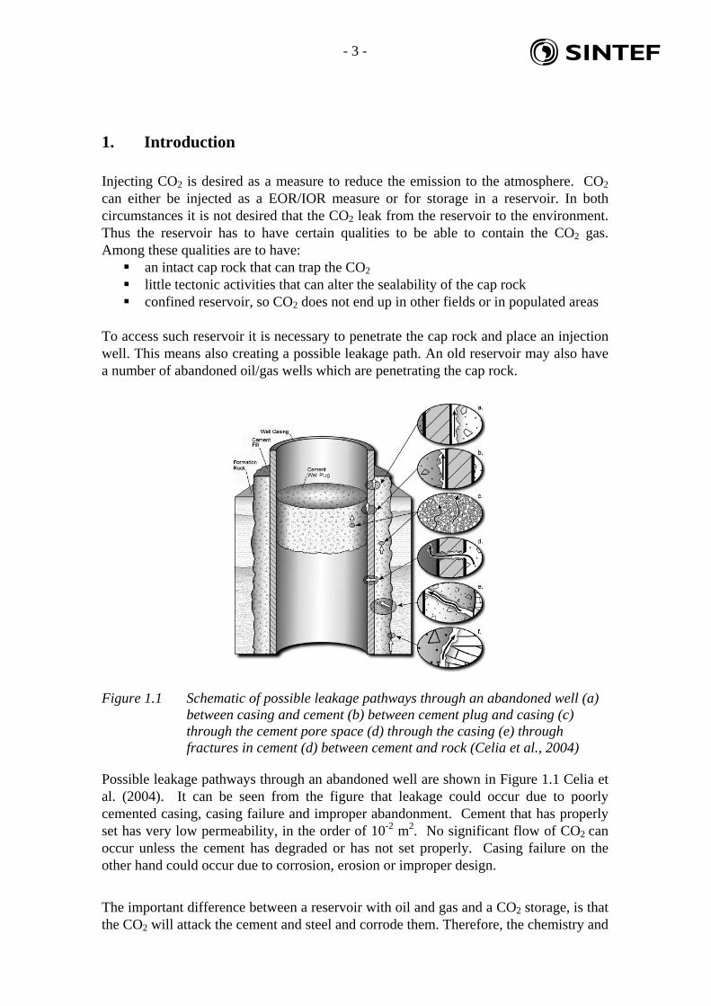
Figure 1.1 Schematic of possible leakage pathways through an abandoned well (a) between casing and cement (b) between cement plug and casing (c) through the cement pore space (d) through the casing (e) through fractures in cement (d) between cement and rock (Celia et al., 2004)
Possible leakage pathways through an abandoned well are shown in Figure 1.1 Celia et al. (2004). It can be seen from the figure that leakage could occur due to poorly cemented casing, casing failure and improper abandonment. Cement that has properly set has very low permeability, in the order of 10-2 m2. No significant flow of CO2 can occur unless the cement has degraded or has not set properly. Casing failure on the other hand could occur due to corrosion, erosion or improper design.
The important difference between a reservoir with oil and gas and a CO2 storage, is that the CO2 will attack the cement and steel and corrode them. Therefore, the chemistry and

- 4 - sd
mechanical integrity of cement and steel becomes important aspects to fully understand prior to choosing the location and choosing how to place and complete the wells. This study will look into the chemical and mechanical aspects of the different cements that are available for CO2 injection wells. It will also look at logging techniques to ensure a good cement job.
- 5 - sd
2. Degradation processes due to CO2 It is known that CO2 reacts with cement even at atmospheric conditions. This can cause loss of strength and integrity of the cement. This chapter covers the theory, laboratory tests, and field experience found in the literature on cement degradation by CO2. In recent years a lot of focus has been directed on this topic due to the increased interest in greenhouse gas storage. The development of new cements and laboratory tests has arisen from the need to ensure the integrity of the CO2 storage. 2.1 General Chemistry
2.1.1 CO2 equilibrium
When ordinary cement is exposed to CO2 gas it will react, especially in a wet environment. CO2 gas will be in equilibrium with the water phase through the equilibria:
CO2 (g) = CO2 (aq) (3.1) CO2 (aq) + H2O = H2CO3 (aq) (3.2) H2CO3 = HCO3
- + H+ (3.3) HCO3
- = CO32- + H+ (3.4)
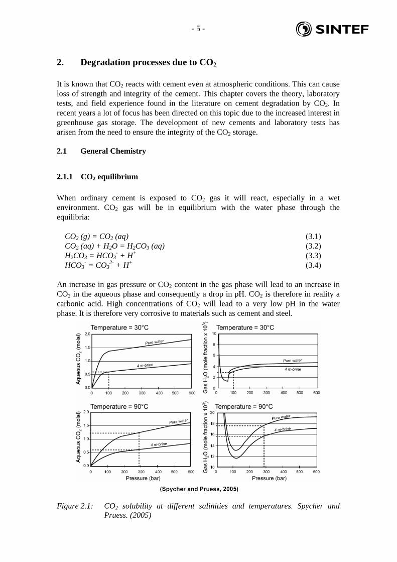
An increase in gas pressure or CO2 content in the gas phase will lead to an increase in CO2 in the aqueous phase and consequently a drop in pH. CO2 is therefore in reality a carbonic acid. High concentrations of CO2 will lead to a very low pH in the water phase. It is therefore very corrosive to materials such as cement and steel.
Figure 2.1: CO2 solubility at different salinities and temperatures. Spycher and Pruess. (2005)

- 6 - sd
The salinity (level of dissolved salts in water) will also influence the solubility of CO2 in the water phase. Figure 2.1 shows how the solubility of CO2 drops as the salt content increases from pure water to 4 molar NaCl. This fact can play a role when comparing the laboratory experiments between different institutes and the field experience.
2.1.2 Calcium Carbonate
One of the minerals found to precipitate in water with high content of calcium and carbonate is calcium carbonate (CaCO3). Calcium carbonate has many polymorphs. The most common are vaterite (spherical crystals), aragonite (needle-shaped crystals), and calcite (cubic crystals) as can be seen in Figure 2.2.
Figure 2.2: SEM images of the three calcium carbonate polymorphs; Vaterite, Aragonite and Calcite. Randhol (2003)
Figure 2.3: The polymorphic abundance (%) of the three CaCO3 phases, Ogino et al. (1987)

- 7 - sd
Calcite is the most thermodynamically stable of the three polymorphs, Randhol (2003). However, the other two phases can precipitate prior to calcite due to slow kinetics, see Figure 2.3. At low temperatures vaterite forms while aragonite forms when the temperature is higher. At even higher temperatures > 80°C calcite will form. As calcite is the thermodynamically most stable phase, vaterite and aragonite will transform to calcite. The transformation to calcite is also limited by kinetics as can be seen from Figure 2.4.
Figure 2.4: Transformation to calcite at different temperatures, Ogino et al. (1987)
2.1.3 Cement and CO2 chemistry
Cement containing Ca(OH)2 will react with the CO2 in the air or water phase as shown in the two equations below respectively:
Ca(OH)2 + CO2 (g) = CaCO3 (s) + H2O (3.5) Ca(OH)2 + H2CO3 (aq) = CaCO3 (s) + 2 H2O (3.6)
This process is called carbonation and leads to a lower porosity due to the precipitation of calcium carbonate takes up a larger volume than the Ca(OH)2. The molar volume increases from 33.6 to 36.9 cm3, Shen et al. (1989).

- 8 - sd
Figure 2.5 illustrates the degradation that would occur. Zone 1 Ca(OH)2 reacts with the CO2 to form CaCO3. If the conditions were such that the acid attack would stop here, one could say that the cement was self healing. This mechanism was proposed by Ron Sweatman in his presentation at 4th Meeting of the Well Bore Integrity Network in Paris 17-18 March 2008. As mentioned previously the CaCO3 will take up more volume and thus decrease the porosity. CaCO3 is less soluble than Ca(OH)2 so Ca(OH)2 will continue to dissolve if acid is present. However, CaCO3 is also soluble in acid.
Figure 2.5: Illustration of the different Zones due to the chemical reactions occurring in the cement core during testing. Zone 1 Ca(OH)2 dissolves and CaCO3 forms. Zone 2 CaCO3 dissolves when Ca(OH)2 is spent. Kutchko et al. (2007)
When all the Ca(OH)2 has reacted the pH will drop from pH=12. Through the CO2 equlibria the concentration of HCO3
- will increase with decreasing pH due to the following reaction:
H+ + CaCO3(s) = Ca2+ + HCO3- (3.7)
Water-soluble calcium bicarbonate then forms, which can easily diffuse out of the cement matrix. This was observed by Kutchko et al. (2007) on the interface between Zone 2 and Zone 3. They also notice that when CaCO3 is dissolved and diffused out, the pH is not buffered inside the cement. Therefore, the next reaction with the calcium silicate hydrate can occur. The reactions in air and water respectively are:
3 CO2 (g) + Ca3Si2O7*4H2O = 3 CaCO3 + 2 SiO2*2H2O (3.8) 3 H2CO3(aq) + Ca3Si2O7*4H2O = 3 CaCO3 + 2 SiO2*2H2O + 3 H2O (3.9)
- 9 - sd
These reactions lead to an increase in porosity due to that the volume of Ca3Si2O7*4H2O is larger than CaCO3(s). It is common to generalize the calcium silicate hydrate to the form: C-S-H as the amounts of calcium to silicate to hydrate varies. However, the reactions above are true for the different types of C-S-H. The silicate hydrate product from the reactions above is also usually an amorphous phase and not crystalline which gives poorer strength of the cement. As there is a large difference in pH outside the cement sample and inside the sample, 2.9 versus 12 there will be a diffusion of acid and it will continue until the whole cement plug is reacted.
2.2 Portland cement
Portland cement is the most widely used cement in the industry. The problem is however that Portland cement is not resistant to CO2. It is not thermodynamically stable in contact with CO2 and will deteriorate over time, Krilov et al. (2000). For CO2 storage over a long time (1000 year perspective) wells with Portland cement will be in risk of leakage. Shen et al. (1989) list the following reactions for Class G cement depending on temperature alone (no CO2):
T = 120°C with excess Ca(OH)2:
C-S-H => Alpha-C2-S-H (3.10) T = 120°C with > 35% Silica:
C-S-H => Tobermorite (C5-S6-H5) (3.11)
T = 150°C Tobermorite (C5-S6-H5) => Xonolite (C6-S6-H) (3.12)
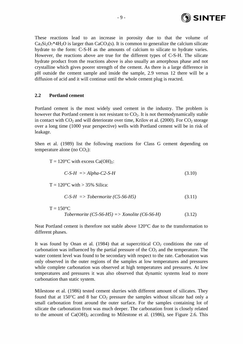
Neat Portland cement is therefore not stable above 120°C due to the transformation to different phases. It was found by Onan et al. (1984) that at supercritical CO2 conditions the rate of carbonation was influenced by the partial pressure of the CO2 and the temperature. The water content level was found to be secondary with respect to the rate. Carbonation was only observed in the outer regions of the samples at low temperatures and pressures while complete carbonation was observed at high temperatures and pressures. At low temperatures and pressures it was also observed that dynamic systems lead to more carbonation than static system. Milestone et al. (1986) tested cement slurries with different amount of silicates. They found that at 150°C and 8 bar CO2 pressure the samples without silicate had only a small carbonation front around the outer surface. For the samples containing lot of silicate the carbonation front was much deeper. The carbonation front is closely related to the amount of Ca(OH)2 according to Milestone et al. (1986), see Figure 2.6. This
- 10 - sd
may be due to that silicate reacts with Ca(OH)2. When the Ca(OH)2 is spent the CaCO3 would start dissolving and increase the porosity. Thus the CO2 can penetrate the sample further. So more silicate would increase the reaction due to that Ca(OH)2 gets spent faster. However, 20% silicate is needed to get below the permeability of 0.1mD which is the API recommendation and silicate is also needed to increase the compressive strength. Tobermorite as a binding phase was found to be poor to withstand CO2 attack. Tobermorite reacts with CO2 and forms aragonite and silica gel which does not protect against CO2.
Figure 2.6: Ca(OH)2 content (%) and carbonation depth (mm) as a function of % added silica, Milestone et al. (1986).
Milestone et al. (1986) concluded that all calcium silicate-based geothermal grouts are subject to carbonation by CO2 fluids. The most important factor is the phases present in the cement, though initial permeability is also a factor. When no Ca(OH)2 is present the attack is rapid and the products formed are porous. Class J cement does not hinder attack either. Milestone et al. (1990) did similar experiments. The samples with silicate had a higher strength than the samples without prior to the experiments. After exposing the samples
- 11 - sd
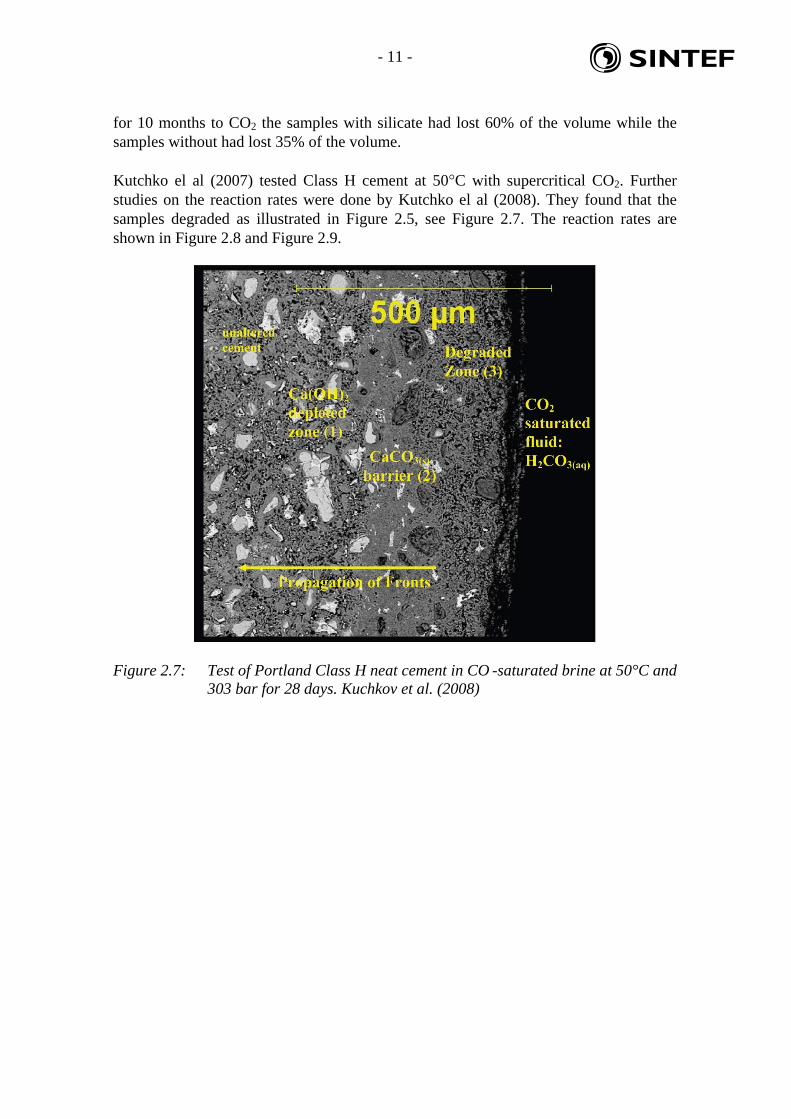
for 10 months to CO2 the samples with silicate had lost 60% of the volume while the samples without had lost 35% of the volume. Kutchko el al (2007) tested Class H cement at 50°C with supercritical CO2. Further studies on the reaction rates were done by Kutchko el al (2008). They found that the samples degraded as illustrated in Figure 2.5, see Figure 2.7. The reaction rates are shown in Figure 2.8 and Figure 2.9.
Figure 2.7: Test of Portland Class H neat cement in CO -saturated brine at 50°C and 303 bar for 28 days. Kuchkov et al. (2008)

- 12 - sd
Figure 2.8: Carbonation depth (mm) vs time1/2(days1/2) at 50°C, Kutchko el al. (2008)
L=(1/b)ln t + (1/b) ln (ab); a=0.6, b=11.1
Figure 2.9: Carbonation depth (mm) vs time (days) at 50°C, Kutchko el al. (2008)

- 13 - sd
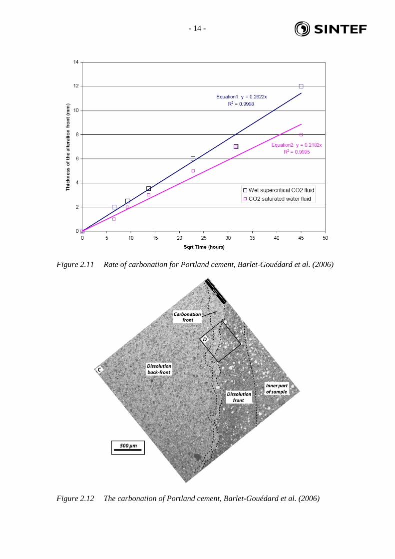
Portland Class G cement was tested by Barlet-Gouédard et al. (2006) in an autoclave at 90°C and 280 bar. Samples were tested in both CO2 saturated water and in supercritical CO2 atmosphere. A drawing of the apparatus is shown in Figure 2.10. The rate of carbonation in both media can be seen from Figure 2.11. The carbonation and porosity alteration of the Portland cement can be seen in Figure 2.12 and Figure 2.13 respectively. They show the same type of zonal degradations as described by Kutchko el al. (2008).
Figure 2.10 Experimental setup for testing cement at supercritical CO2 conditions Barlet-Gouédard et al. (2006)
- 14 - sd
Figure 2.11 Rate of carbonation for Portland cement, Barlet-Gouédard et al. (2006)
Figure 2.12 The carbonation of Portland cement, Barlet-Gouédard et al. (2006)

- 15 - sd
Figure 2.13 The porosity alterations in Portland cement. Excerpt of Figure 2.12, Barlet-Gouédard et al. (2006)
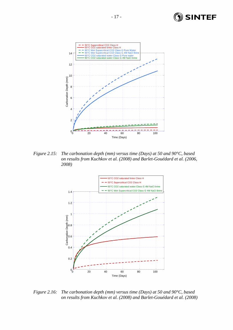
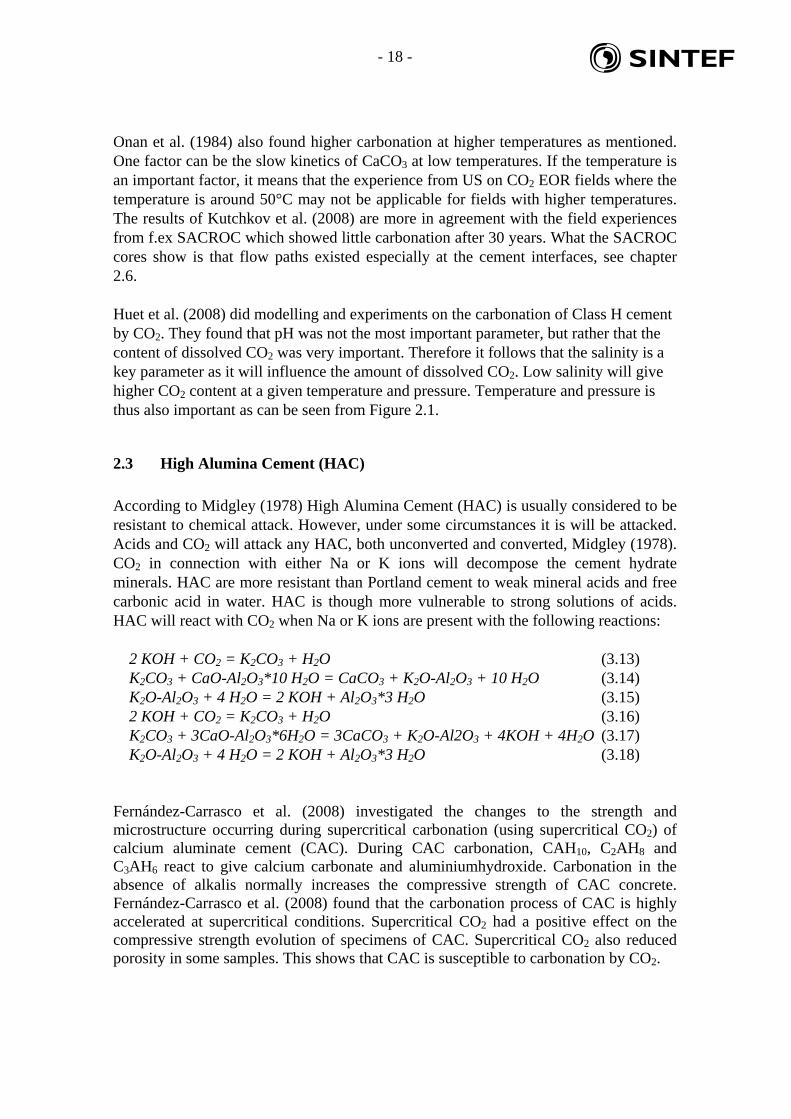
The rate of carbonation in the Barlet-Gouédard et al. (2006) experiments was much higher than that of Kuchkov et al. (2008). The difference in carbonation rate is shown in Figure 2.15. As can be seen there is a huge difference in how far the carbonation front has reached in the 90 °C experiments compared to the 50°C experiments. However, the two experiments are not directly comparable due to differences in the testing procedure and cement used. Kuchkov et al. (2008) pointed out the main differences between their experiments and those of Barlet-Gouédard et al. (2006), see Table 2.1.
Table 2.1: Main differences between experiments of Barlet-Gouédard et al. (2006) and Kuchkov et al. (2008)
Barlet-Gouédard et al. (2006) Kuchkov et al. (2008) Class G cement Class H cement 72 h curing time 28 day curing time an antifoam agent, dispersant, and retarder added to the cement mix to optimize slurry properties
neat cement
deionized water 0.17 M NaCl 90 °C 50 °C

- 16 - sd
Barlet-Gouédard et al. (2008) did additional experiments with a 4 molar NaCl brine solution using same setup and cement as the Barlet-Gouédard et al. (2006) experiments. This was done to simulate downhole formation water conditions. As mentioned earlier the solubility of CO2 in water is lower at increased salinity compared to pure water. The cement cores were tested for two days and the carbonation was measured. The result from the previous experiments with pure water is compared to the result from the 4 molar brine experiments in Figure 2.14. It can be seen that the carbonation in 4 molar NaCl is only a tenth of what was observed for pure water. This result agrees much better with the results Kutchkov et al. (2008) got and field experience. In addition to lower the CO2 solubility in water, higher salinity also usually leads to less precipitation as the kinetics are more stable, Randhol (2003). However, why there is such a large difference between the two test is hard to explain without more research on the reactions going on during carbonation. It must also be commented that the experiments done by Kutchkov et al. (2008) had only a brine of 0.17M which is more close to pure water than 4 molar NaCl. It must therefore be assumed that the temperature is also important, as many have concluded.
Figure 2.14: Experiments with Portland cement in supercritical CO2 gas and CO2 saturated fluid at 90°C and 280 bar. The water phase was pure water and 4 molar NaCl brine. V. Barlet-Gouédard et al. (2008)
- 17 - sd
0
2
4
6
8
10
12
14
0 20 40 60 80 100
50°C Supercritical CO2 Class H50°C CO2 saturated brine Class H90°C Wet Supercritical CO2 Class G Pure Water90°C Wet Supercritical CO2 Class G 4M NaCl Brine90°C CO2 saturated water Class G Pure water90°C CO2 saturated water Class G 4M NaCl brine
Ca
rbon
atio
n D
ept
h (
mm
)
Time (Days)
Figure 2.15: The carbonation depth (mm) versus time (Days) at 50 and 90°C, based on results from Kuchkov et al. (2008) and Barlet-Gouédard et al. (2006, 2008)
0
0.2
0.4
0.6
0.8
1
1.2
1.4
0 20 40 60 80 100
50°C CO2 saturated brine Class H
50°C Supercritical CO2 Class H
90°C CO2 saturated water Class G 4M NaCl brine
90°C Wet Supercritical CO2 Class G 4M NaCl Brine
Ca
rbon
atio
n D
ept
h (
mm
)
Time (Days)
Figure 2.16: The carbonation depth (mm) versus time (Days) at 50 and 90°C, based on results from Kuchkov et al. (2008) and Barlet-Gouédard et al. (2008)
- 18 - sd
Onan et al. (1984) also found higher carbonation at higher temperatures as mentioned. One factor can be the slow kinetics of CaCO3 at low temperatures. If the temperature is an important factor, it means that the experience from US on CO2 EOR fields where the temperature is around 50°C may not be applicable for fields with higher temperatures. The results of Kutchkov et al. (2008) are more in agreement with the field experiences from f.ex SACROC which showed little carbonation after 30 years. What the SACROC cores show is that flow paths existed especially at the cement interfaces, see chapter 2.6. Huet et al. (2008) did modelling and experiments on the carbonation of Class H cement by CO2. They found that pH was not the most important parameter, but rather that the content of dissolved CO2 was very important. Therefore it follows that the salinity is a key parameter as it will influence the amount of dissolved CO2. Low salinity will give higher CO2 content at a given temperature and pressure. Temperature and pressure is thus also important as can be seen from Figure 2.1.
2.3 High Alumina Cement (HAC)
According to Midgley (1978) High Alumina Cement (HAC) is usually considered to be resistant to chemical attack. However, under some circumstances it is will be attacked. Acids and CO2 will attack any HAC, both unconverted and converted, Midgley (1978). CO2 in connection with either Na or K ions will decompose the cement hydrate minerals. HAC are more resistant than Portland cement to weak mineral acids and free carbonic acid in water. HAC is though more vulnerable to strong solutions of acids. HAC will react with CO2 when Na or K ions are present with the following reactions:
2 KOH + CO2 = K2CO3 + H2O (3.13) K2CO3 + CaO-Al2O3*10 H2O = CaCO3 + K2O-Al2O3 + 10 H2O (3.14) K2O-Al2O3 + 4 H2O = 2 KOH + Al2O3*3 H2O (3.15) 2 KOH + CO2 = K2CO3 + H2O (3.16) K2CO3 + 3CaO-Al2O3*6H2O = 3CaCO3 + K2O-Al2O3 + 4KOH + 4H2O (3.17) K2O-Al2O3 + 4 H2O = 2 KOH + Al2O3*3 H2O (3.18)
Fernández-Carrasco et al. (2008) investigated the changes to the strength and microstructure occurring during supercritical carbonation (using supercritical CO2) of calcium aluminate cement (CAC). During CAC carbonation, CAH10, C2AH8 and C3AH6 react to give calcium carbonate and aluminiumhydroxide. Carbonation in the absence of alkalis normally increases the compressive strength of CAC concrete. Fernández-Carrasco et al. (2008) found that the carbonation process of CAC is highly accelerated at supercritical conditions. Supercritical CO2 had a positive effect on the compressive strength evolution of specimens of CAC. Supercritical CO2 also reduced porosity in some samples. This shows that CAC is susceptible to carbonation by CO2.
- 19 - sd
2.4 Phosphate based cements
Brookhaven National Laboratory supported by DOE, Halliburton, UnoCal Corporation, and CalEnergy Operating Corporation has developed a phosphate based cement. The cement is claimed to have outstanding resistance to CO2 and acid at brine temperatures up to 320°C, Sugama T (2006). The Calcium Aluminate Phosphate (CaP) cement is commercialised by Halliburton under the name ThermaLock. More information on the ThermaLock cement is given in chapter 2.8. Another phosphate based cement has been developed by Argonne National Laboratory, Wagh et al. (2005a, 2005b). It is based on Magnesium Potassium Phosphate. Magensium is less prone to carbonation compared to calcium and should have better resistance to CO2. The cement is developed for the Arctic conditions with very low temperatures. No tests of the resistance to CO2 have been found so how well the cement behaves in a CO2 environment is not known.
2.5 Self healing cement (SHC)
New cement formulations are under development by both Halliburton and Schlumberger, originally targeting gas storage applications, Moroni et al. (2007) and Moroni et al. (2008). These cements have self-healing, swelling properties and have therefore been named self-healing cements (SHC). Unique proprietary additivies react to hydrocarbons by swelling, thus mending accidental cracks and microannuli by sealing the leak path. This promising technology will perhaps open the door for the development of a SHC class activated by CO2 contact instead of hydrocarbon contact.
2.6 Field experience
Carey et. al. (2007) did a study of the cement from the SACROC unit in West Texas, USA. The 240 m thick reservoir is located at 2100 m depth and has a temperature of 54C and a pressure of 180 bar. The reservoir is limestone with 10-100 mD permeability and around 10% porosity. The cementing at total depth was neat Portland cement. The well 49-6 was drilled in 1950 and was first exposed to CO2 in 1975. In the following years it was a producer for 10 years in low pressure environment. The next 7 years it was an injector (high pressure) and 110 000 tonnes of CO2 passed through the well according to Carey et. al. (2007) Samples of the casing and cement was taken from about 6-4m above the caprock-reservoir contact, see Figure 2.17. Shale sample was also collected. The cement was analysed and it was found that it had been partly carbonated. The cement that was in contact with the shale rock is heavily carbonated. The cement close to the casing is pure carbonate like a vein filling. No obvious proof of direct CO2 interaction with the shale was found. The permeability of the cement was found to be higher than pristine Portland cement. SEM imaging showed that CaCO3 had precipitated in the void spaced.

- 20 - sd
Figure 2.17 Photograph of samples recovered from well 49-6 showing the casing (left), gray cement with a dark rind adjacent to the casing, 5-cm core of gray cement, gray cement with an orange alteration zone in contact with a zone of fragmented shale, and the shale country rock, Carey et. al (2007)
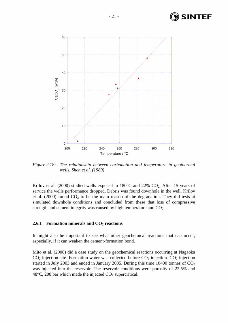
Generally it was concluded that the structural integrity of the Portland cement was adequate to prevent significant transport of fluids. However, CO2 was found to have migrated along the cement casing and cement shale interfaces for some time. Shen et al. (1989) examined geothermal wells and the carbonation by CO2 of Class G cement. To stabilise Portland cement at high temperatures, silica flour is added. In geothermal well cements there is little or no Ca(OH)2, so the C-S-H phases can be attacked directly by CO2. The CO2 content for the wells were 12200 ppm CO2 (0.20 mol/kg) while the temperatures were in the range of ~ 200-300°C. They found that the carbonation was dependant on temperature, CO2 concentration and location. Both carbonated and uncarbonated cement had fractures and fissures. This is probably due to the thermal cycles in the well. Shen et al. (1989) found that the number of shutdowns correlated with the increase in permeability. This fits with the observed fractures as the sharp changes in temperature will lead to strains in the cement and likely cause fracturing of the cement. There was no evident correlation between carbonation extent and porosity. However, temperature and amount of calcium carbonate formed in the cement due to CO2 showed a linear relationship, see Figure 2.18. Increasing temperature gave increased amount of CaCO3.
- 21 - sd
0
10
20
30
40
50
60
200 220 240 260 280 300 320
Ca
CO
3 (
wt%
)
Temperature / °C
Figure 2.18: The relationship between carbonation and temperature in geothermal wells. Shen et al. (1989)
Krilov et al. (2000) studied wells exposed to 180°C and 22% CO2. After 15 years of service the wells performance dropped. Debris was found downhole in the well. Krilov et al. (2000) found CO2 to be the main reason of the degradation. They did tests at simulated downhole conditions and concluded from these that loss of compressive strength and cement integrity was caused by high temperature and CO2.
2.6.1 Formation minerals and CO2 reactions
It might also be important to see what other geochemical reactions that can occur, especially, if it can weaken the cement-formation bond. Mito et al. (2008) did a case study on the geochemical reactions occurring at Nagaoka CO2 injection site. Formation water was collected before CO2 injection. CO2 injection started in July 2003 and ended in January 2005. During this time 10400 tonnes of CO2 was injected into the reservoir. The reservoir conditions were porosity of 22.5% and 48°C, 208 bar which made the injected CO2 supercritical.
- 22 - sd
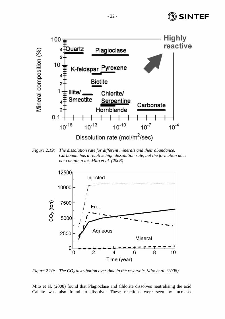
Figure 2.19: The dissolution rate for different minerals and their abundance. Carbonate has a relative high dissolution rate, but the formation does not contain a lot. Mito et al. (2008)
Figure 2.20: The CO2 distribution over time in the reservoir. Mito et al. (2008)
Mito et al. (2008) found that Plagioclase and Chlorite dissolves neutralising the acid. Calcite was also found to dissolve. These reactions were seen by increased

- 23 - sd
concentrations of Ca, Mg, Fe and Si concentrations after injection. The reactivity of the different minerals is shown in Figure 2.19. It can be seen that Calcite is the mineral most readily to dissolve. The CO2 distribution is show in Figure 2.20. This shows that the amount of free CO2 drops while there is some increase in mineral bound CO2. Shiraki et al. (2008) did core-flooding experiment at downhole conditions of the Tensleep sandstone reservoirs in northern Wyoming, USA. The temperature and pressure during the experiments were 80°C and 166 bar. Cores of the sandstone from the reservoir were used along with synthetic brine. The cores were cemented by dolomite and anhydrite. According to Shiraki et al. (2008) three major reactions took place during flooding:
1. dissolution of dolomite 2. alteration of K- feldspar to form kaolinite 3. precipitation or dissolution of anhydrite (depending of the brine)
The sample solutions remained undersaturated with respect to carbonates. The permeability of all the cores (except when anhydrite was dissolved) decreased. Kaolinite crystal growth in the pore throats was thought to be likely reason for the reduction of the permeability There may be alterations either positive or negative in the formation itself due to CO2. This should be studied and mapped further in light of how it can affect the cement-formation bond.
2.7 Cement additives
According to Beddoe et. al. (2005) adding quartz to Portland cement in order to make it more acid resistant will leave only the cement paste affected by CO2. The cement can therefore be enhanced in order to reduce the carbonation rate. Cement deterioration will still occur but the degree of tortuosity induced by the aggregate particles will decrease the rate. Addition of Microsilica to the Portland Grade G cement gave lower permeability and better mechanical strength according to Noik et al. (1998) The CO2 resistance was not tested though. It is reasonable to assume that additives to Portland cement such as silicates, microsilicate, latex, polymers, can change the properties of the cement and reduce the amount of Portland cement, but it will not hinder the carbonation from occurring due to that the Portland cement is thermodynamically unstable in contact with CO2. Kutchko et al. (2007b) tested Portland cement with different additives. Class H cements with 6 % Bentonite was completely degraded in 9 days, leaving behind calcite crystals and silica gel. 35:65 Pozzalon/cement mixture with Type F fly ash and 2% Bentonite was also tested. Kutchko concluded after the tests that all tested additives change the degradation process of the cement and increased it significantly.

- 24 - sd
2.8 Acid resistant cements
The Thermalock cement is claimed to have outstanding resistance to CO2 and acid at brine temperatures up to 320°C, Sugama T (2006). The cement is CaP phosphate cement.
Figure 2.21: Cement test for CO2 resistance at 60°C. ThermaLock versus Class H Portland with and without Latex addition, (Haliburton)
Test has been performed in H2SO4 solutions of low pH~1.1 with HCO3- as CO2 source.
One risk of testing with H2SO4 is the possibility of CaSO4 precipitation as it could lower the permeability and would not dissolve like calcite in acid. According to Brothers (2005) testing showed that Thermalock had a 3 % weight loss compared to 50 % weight loss of Portland cement. The Thermalock cement has been used in geothermal wells and CO2 injection wells. ThermaLock is not compatible with the Portland cement and must be handled separately. Additives for Portland are therefore not compatible either. Schlumberger has also developed a CO2 resistant cement which they have tested, Barlet-Gouédard et al. (2006, 2008). The cement is not described other than that it has reduced amount of Portland cement. The test revealed that carbonation occurred, but that the level was lower and more homogeneously. Comparing to pure Portland cement it was concluded that this cement was more CO2 resistant. Barlet-Gouédard et al. (2008b) studies several cements and their strength over time. The samples where exposed to the same experiments as described in section 2.2. The results were presented at 4th Meeting of the Well Bore Integrity Network in Paris 17-18 March 2008 and are given in Table 2.3. The colour codes are explained in Table 2.2. Barlet-Gouédard V (2008b) found that none of the tested cements except the CO2 Resistant cement were resistant to CO2 degradation and mechanical degradation as a result. The latter cement is now named EverCrete by Schlumberger, ref Barlet-Gouédard V (2008a). It is reported to be Portland compatible and can be used with the additives developed for
- 25 - sd
Portland cement. The temperatures it can be used for is 40-110°C. ref www.slb.com/evercrete. Schlumberger recommend designing an EverCRETE system with in-built expansion to pre-stress the cement sheath such as the risk for tensile cracks be lowered, often encountered in cyclic injection wells Nagelhout et al (2005). Schlumberger further stress that if the ECD is too close to the fracture gradient, a light version of the EverCRETE cement can be prepared. According to Schlumberger, the proprietary EverCRETE formulation gives water permeability in the µD range, well below that for standard foamed cement formulations. A paper on the cement is going to be released in February 2009.
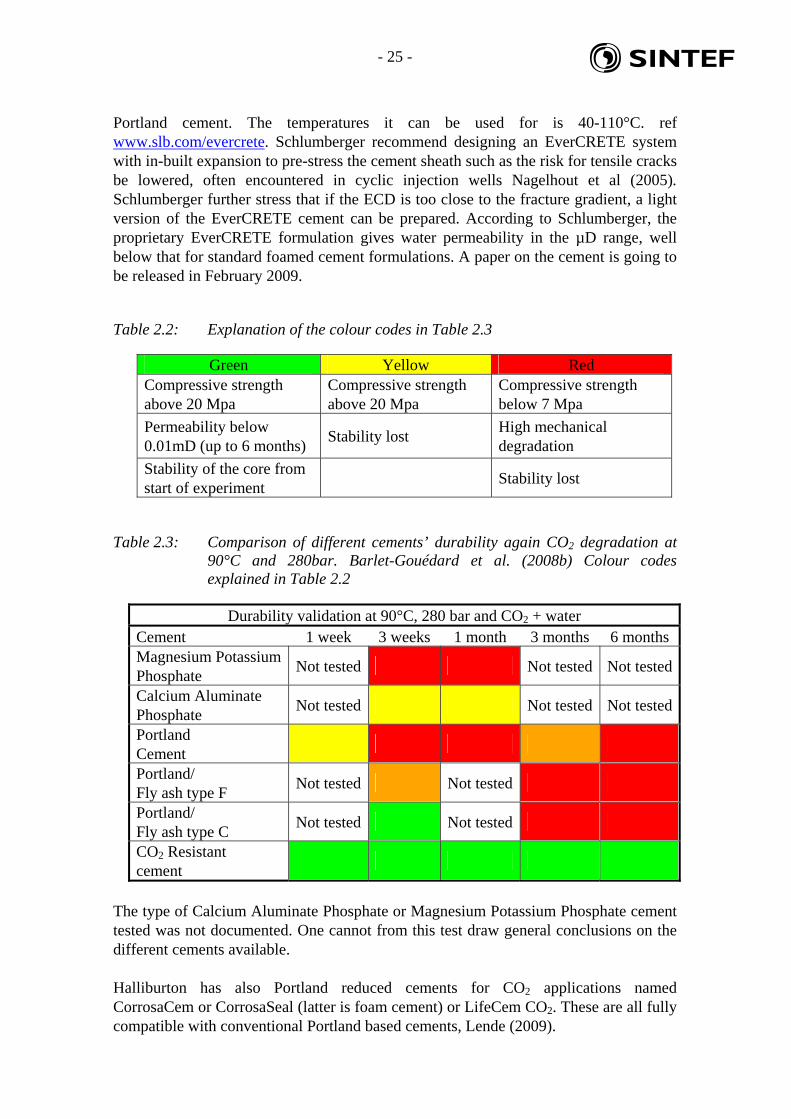
Table 2.2: Explanation of the colour codes in Table 2.3
Green Yellow Red Compressive strength above 20 Mpa
Compressive strength above 20 Mpa
Compressive strength below 7 Mpa
Permeability below 0.01mD (up to 6 months)
Stability lost High mechanical degradation
Stability of the core from start of experiment
Stability lost
Table 2.3: Comparison of different cements’ durability again CO2 degradation at 90°C and 280bar. Barlet-Gouédard et al. (2008b) Colour codes explained in Table 2.2
Durability validation at 90°C, 280 bar and CO2 + water Cement 1 week 3 weeks 1 month 3 months 6 months Magnesium Potassium Phosphate
Not tested Not tested Not tested
Calcium Aluminate Phosphate
Not tested Not tested Not tested
Portland Cement
Portland/ Fly ash type F
Not tested Not tested
Portland/ Fly ash type C
Not tested Not tested
CO2 Resistant cement
The type of Calcium Aluminate Phosphate or Magnesium Potassium Phosphate cement tested was not documented. One cannot from this test draw general conclusions on the different cements available. Halliburton has also Portland reduced cements for CO2 applications named CorrosaCem or CorrosaSeal (latter is foam cement) or LifeCem CO2. These are all fully compatible with conventional Portland based cements, Lende (2009).
- 26 - sd
2.9 Summary
It is not a question whether the Portland type of cement is degrading due to acid attack by CO2 or not. The main question remaining is how fast the degradation occurs and how it affects the integrity of the cement downhole. From the various experiments done it can be seen that the reaction rate is not very high. It can be noticed that as the temperature increases the degradation increases. This is quite expected from that reaction kinetics usually increase with temperature. By extrapolating the laboratory results one is still left with a large amount of years before some meters have been degraded, Figure 2.15. The slow degradation is most likely due to that the process is diffusion controlled and that the permeability of cement is very low typically 0.01 mD. The results from 90°C and pure water show that the cement can rapidly loose its sealing capability between formation and casing if the carbonation occurs either horizontally or through cracks in the cement. The slow, at least at low temperatures, reaction of CO2 with cement shows that the mechanical integrity of the cement is of great importance. It is important to hinder debonding at the interface between casing and cement or cement and formation or fractures/channels in the cement. If there are larger leak paths due to cracking/debonding of the cement the chemical degradation can further weaken the cement through these paths.
- 27 - sd
3. Mechanical factors influencing wellbore cement-sheath integrity
In this section, we will review published literature describing the mechanical aspects of cement degradation. If chemical reactions leading to cement degradation are based on diffusion of some corroding fluid inside the intact cement matrix, and deemed too slow to be of any practical concern in the presence of more than one meter long cement plug, mechanically induced fracture propagation will be an almost instantaneous integrity threat, should the conditions for its appearance incur. Such fractures may appear in the cement sheath itself, or at its interface with either the steel casing or the rock formation. 3.1 Debonding of cement and fracturing at the rock formation interface
3.1.1 Cement in contact with shale
Depending on water activity of cement and shale, water could flow into the cement, leading to an exothermic reaction when setting, with cement pore pressure diminishing and cement shrinking. Shrinkage of cement can leak to fractures at the interface with the shale Ladva et al. (2005). Diffusion and exchange of ions between the cement and clay can also create fractures in the clay itself, between ion-depleted and not yet depleted zones. 3.1.2 Cement in contact with filter cake
The same shrinkage phenomenon can occur, with cement drawing water from the filter cake. This has as effect of increasing the strength of the cake in contact with the cement, by dehydration. It is found that the shear bond strength of the cement with rock is greatly reduced in the presence of a filter cake. 3.1.3 Mechanical formation damage
Most sandstones exhibit a lower compressive strength when the water saturation increases, if they are preferentially water-wet (Figure 3.1). One must thus take care when drilling with water-based mud, as the near wellbore zone can become significantly weaker than appreciated from laboratory mechanical testing. This can imply the creation of a micro-annulus inside the formation, depending on the evolution of the wellbore pressure, even if the cement job is deemed a success. This is why it is recommended to test the strength of the encountered formation with all fluids it will encounter during drilling and completion (cementing) operations. Even in the case of oil-based drilling fluids, water-based spacers could still affect the formation, after filter cake displacement.

- 28 - sd
Sp
ecif
ic c
utt
ing
en
erg
y E
s(M
Pa
)
Distance below rock surface (mm)
Dry
Oil
Brine
WBM
Sp
ecif
ic c
utt
ing
en
erg
y E
s(M
Pa
)
Distance below rock surface (mm)
Sp
ecif
ic c
utt
ing
en
erg
y E
s(M
Pa
)
Dry
OilWBM
Brine
Distance below rock surface (mm)
Figure 3.1: Reduction in rock strength after exposure to different fluids and filtration with water-based mud, as measured with the scratch technique (Cerasi et al. (2008)).
3.2 Cement shrinkage and fracturing
Normal cement, without additions targeting shrinkage inhibition, tends to shrink when setting in the wellbore annulus Lende (2008). In the presence of a poor bond with the surrounding formation, as seen above, this means that an open annulus can occur, meaning the loss of zonal isolation. However, even if the bond with the formation is very strong, shrinkage will then induce stresses in the cement bulk. Tensile fracturing may occur, with loss of isolation in the middle of the cement. Alternatively, compression shear failure can lead to radial fractures appearing in the cement bulk. These same patterns will occur inside the steel casing (see Figure 3.3).
Tensile fracture
Shear fracture
Tensile fractures
Figure 3.2: Fractures appearing in cement shrinkage.

- 29 - sd
3.3 Cement mechanical parameter testing and analysis
Induced stresses in the annular cement can often be tensile. It is important to test the tensile strength under downhole conditions, i.e. under pressure and temperature. Testing at different stress load rates yields different tensile strength values according to Dillenbeck et al. (2005). Desired mechanical properties for cement: low Young’s modulus, low friction angle and high cohesion. Bulk shrinkage due to cement hydration should be avoided. These properties can be achieved with foamed cement, but foamed cement does not perform well at high temperature. Figure 3.3 shows the type of damage occurring in cement for various events in a well’s life. In Figure 3.4, radial and shear cracks are apparent in a cement sample subjected to cyclic pressure testing (Heathman et al. (2006)). It is important to evaluate the initial state of stress in a material, existing prior to any additional loading (such as in-situ stresses in a reservoir). This represents how far the material is from failure and thus how much loading it can sustain. According to Saint-Marc et al. (2008), knowing the initial stress state allows one to take appropriate actions to avoid failure of the material, given a known stress path it will be exposed to. Since hydration of cement leads to increased porosity, cement can be treated as a poro-elastic material and characterized by submitting it to usual rock mechanics testing such as triaxial compression tests. There is a percolation threshold in the setting of cement: below the threshold, the cement can be viewed as a liquid, while above it, it should be modeled as a porous solid. The poro-elastic parameters such as the Young’s modulus are a function of the hydration degree. As the cement hydrates, water is bonded to the solid grains, the free fluid volume decreases and with it the pore pressure, reaching sometimes cavitation pressure. Debonding from the casing or the formation can be detected by calculating the radial effective stresses and comparing it with the bonding strength between cement and formation and between cement and pipe. The cement can be damaged by shear processes, whereby the shear stress rises above the shear strength. Also, tensile radial cracks will appear when the hoop effective stress goes below the tensile strength. A further tensile damage mechanism is disking, where the axial effective stress is such that tensile strength is exceeded. Total has developed a finite element (FEA) software (SealWell) capable of calculating the stress state in the cement sheath and indicating the occurrence and type of damage incurred under given in-situ stress conditions. Halliburton has also developed new FEA tools from its earlier WellLife code from 2000; the new software can model multiple casings and associated annuli with cement, making it unique in the industry. This development is essential for a correct analysis of thermal wells (Lende, 2009).

- 30 - sd
Figure 3.3: Damage types in cement sheaths. Results obtained with the Halliburton WellLife FEA software (Heathman et al. (2006)).
Figure 3.4: Damage (fractures) occurring in cyclic pressure testing of conventional cement in a test conducted by Halliburton (Heathman et al. (2006)).

- 31 - sd
Figure 3.5: Typical fractures and failed rock zones appearing in wellbores subject to anisotropic stress conditions (Orlic et al. (2008)).
Typical fracturing of formation, with formation of breakouts and tensile fractures, is shown in Figure 3.5. The cement job has to be of sufficient quality to seal these possible fractures (Orlic et al. (2008)). The tensile strength of conventional cements is usually taken to be 1/10th of its compressive strength (10 to 13 bar), which is also typical for the tensile bond strength to the formation. Axial deformation in wells (see Figure 3.6) under reservoir depletion conditions or in injection mode can lead to debonding of cement from casing, since the stiffness of steel is much greater then that of the formation and cement: the casing will practically not deform while the cement and formation will.
Figure 3.6: Axial deformation of a well under reservoir depletion or in an injection scenario, leading to cement de-bonding (Orlic et al. (2008)).
Conventional Class G cements are not suited for stress exposure in injection wells with temperature and pressure changes occurring frequently (Pedersen et al. (2006)). The new sealants have a particle size distribution (trimodal) enabling them to be more flexible and avoid tensile failure during stress cycling. The cement is engineered to expand more than needed to seal the annulus space, thus reducing the cement’s porosity as further expansion is impossible.

- 32 - sd
4 mechanical parameters of the cement have to be determined to engineer it correctly such that it can withstand a given stress state:
compressive strength; tensile strength; Young’s modulus; Poisson’s ratio.
The mechanical properties of the formation are also of utmost importance: a soft formation (low Young’s modulus) will deform when the cement expands, creating the risk of opening a micro-annulus against the casing (Pedersen et al. (2006)). 3.4 Effect of temperature on cement integrity
In well-consolidated permafrost formations, one can drill and cement with warm fluids , since thawing of the formations is not a major problem, Maier et al. (1971). Accelerated API Class A, C, or G cement with a slurry temperature of 40° to 60°F, preferably densified, could be used. A high-alumina cement, with or without fly ash, maintained at an above-freezing slurry temperature should also be successful. Circulating warm displacement water or injecting steam to keep the slurry warm until it sets are ways to address cementing in the arctic. Shallow formations with unconsolidated sand exhibit strength due to the frozen water acting as binding agent. Requirements for cementing in this type of permafrost are:
1. prevention of hole enlargement due to melting and erosion while drilling, 2. a cement capable of curing rapidly that sets at the existing borehole temperature
without excessive heating of the mixing or displacing water and 3. a cement that sets with a low heat of hydration to prevent additional melting of
the permafrost. The cement should have built-in protection from freezing before the slurry sets. API Class A, C. or G cements do not appear suitable for cementing through an unconsolidated permafrost zone where warmed fluids should not be used. At the other extreme, high temperature wells also take their toll on cement: data from fields producing CO2-rich fluids at high temperature show that frequent shut-ins provoke tensile stresses in excess of the cement’s tensile strength, provoking widespread fissuring and cracking Shen et al. (1989)
3.5 Effect of confinement pressure
Conductive cement pathways are according to Huerta et al. (2008):
1. microchannelling debonding of cement with either casing or formation
2. micro fractures in the cement 3. gas/mud channelling in the cement matrix

- 33 - sd
Class H neat cement was used during the experiments. Huerta et al. (2008) did experiments with cement cores with an induced fracture along the length of the core. They measured the aperture as a function of confining pressure and acidification of the cores. The two cores were carefully altered so that they would not fit completely when put together for the pressure test. Water was flooded through the cores at different confining pressures. The two interfaces of the cores were dipped in HCl acid (pH ~ 0.3). The cores were reassembled and tested again. After this test the cores were soaked in acid for 24 hours. Extensive acidification had occurred at the interface. When the cores were tested again, plastic deformation was observed leading to "sealing" of the crack. This can be seen in Figure 3.7. The first acidification leaded to larger aperture, possibly due to loss of material at the interfaces prior to assembly. At the same time the strength of the rock was not weakened substantially due to the acid exposure. Huerta et al. (2008) concluded that further studies should be conducted for cyclic loads influence on cracks.
Figure 3.7: Stress testing of fractures what has either been subjected to acid or not. Huerta et al. (2008)

- 34 - sd
3.6 Effect of fractures on permeability
Bachu et al. (2008) did experiments on cemented annulus measuring relative permeability. A solid rod was cemented into a core of Class G cement, see Figure 3.8. The core was placed in a sleeve and then into a core holder. Confining pressure was 241 bar. Temperature during the flooding experiments was 60°C and the pressure was adjusted so that the pore pressure was ~138 bar.
Figure 3.8: The experimental cores for testing permeability in Class G cement with or without fractures. (a) pefect cement (b) cement with a controlled aperture. Bachu et al. (2008)
In the first set of experiments CO2 saturated brine was flooded for 90 days at 60°C. Reduced permeability was observed probably due to the carbonation and calcite precipitation in the pore space. In the second set of experiments they changed from CO2 to ethane. This was done to avoid chemical reactions with the cement. They found that with cracks having an aperture size of 0.01-0.3 mm the effective permeability was in the range 0.1-1mD.
3.7 Combination of fibre and elastomer additives
As discussed in the previous sections, it is apparent that reducing the Young’s modulus of the cement, or increasing its elasticity, is a means to alleviate debonding due to shrinkage and the appearance of cracks. One way to increase elasticity is to add elastomers to the cement mix. However, reducing the Young’s modulus is usually accompanied by a reduction in compressive strength. On the other hand, adding elongated fibres to the mix has been shown to successfully increase the compressive strength of the set cement. Adding fibres however also increases the Young’s modulus. A new idea consists of mixing carboxylated nitrile rubber particles and polypropylene fibres, such that a good compromise elastic behaviour of the cement is obtained Yao et al. (2007). The new additive is called “PJ agent”. No mention is however made of its appropriateness for CO2 exposure.
- 35 - sd
Certain fibres added to the cement mix can also reduce the Young’s modulus, as designed by Halliburton for originally high stiffness cement mixes (Lende, 2009).
3.8 Field experience
Loizzo et al. (2008) looked on the CRC-1 well in the Otway CO2 storage field. CRC-1 was designed and completed to be a top-tier well. Great care was put into making this well as perfect as possible. One centraliser was used per joint even for vertical section. However, wash-out and break-out was experienced from the cap rock. This and a small hole deviation lead to that the tail slurry was contaminated by the lead slurry. This resulted in high porosity solid channels along the narrow side of the annulus in the cap rock. This gave only 12 meter of logged good cement across the cap rock. Whether 12 meter is enough can be debated, but it shows that making a perfectly cemented well is difficult.
- 36 - sd
4. Cement logging
4.1 Temperature logging
Conventional temperature logs can be used to find the top of the cement. The logs must be performed while the cement sets to measure the temperature change due to the chemical reactions in the cement. This is thus dependent on the feasibility to run the temperature logs in the time frame.
4.1.1 Distributed Thermal Sensor
The Distributed Temperature Sensor (DTS) is a permanently installed fiber optic cable along the tubing/casing, Figure 4.1 and Figure 4.2. This can be used to measure the temperature at any time. DTS utilizes laser light to measure the temperature along a fiber optic cable. Raman backscatter is temperature dependent and this is what is utilized in DTS to measure the temperature. According to Hunter et al. (2007) a resolution of 10 cm or less is possible, but not economically viable. The advantage of DTS is that one can measure the temperature along the whole cable almost instantaneously. The measurements can be repeated within minutes to obtain a time dependent temperature profile, see Figure 4.3. Hunter et al. (2007) examined if it is possible to detect CO2 by temperature logging. They looked at two types of temperature signals; static and dynamic. The static signal will give information about the thermal properties in the rock. CO2 changes the rocks thermal properties when entering the pores according to Hunter et al. (2007). If this is detectable, one can see where the CO2 goes by comparing tests from different time steps. The dynamic signal will show the thermal effect of moving CO2. Leakages into the well or through the caprock, can be detected due to the cooling effect caused by the expansion of the supercritical CO2. Hunter et al. (2007) concluded from their theoretical studies that thermal methods can be useful for monitoring CO2. Either leakage occurring over a short time, or CO2 saturation changes in the reservoir over a long time. There are a number of conditions that need to be fulfilled such as porosity and saturation level. DTS has been used in hydrate gas wells to log the temperature, Fujii et al. (2008). It was found from the logged data that the resolution was 0.1°C. The accuracy was 1.5°C when calibrated at the surface and referenced to downhole temperature logs.

- 37 - sd
Figure 4.1 Distributed Temperature Sensor illustration. Henninges et al. (2008), GFZ Potsdam
Figure 4.2: Permanent installation of cable behind casing. DTS cable on left hand side. Henninges et al. (2008), GFZ Potsdam

- 38 - sd
Figure 4.3: Temperature monitoring during stage cementations in three wells, Henninges et al. (2008), GFZ Potsdam
Figure 4.4: Temperature changes from setting of the cement measured by DTS, Henninges et al. (2008), GFZ Potsdam
- 39 - sd
4.2 Sonic tool
4.2.1 CBL
This device is implemented on a variety of tools and has been available since the 50’s, later to be combined with the Variable Density Log. It sends sound waves out, at a frequency of 20 kHz and picks reflected waves further down on the tool, ref. http://www.slb.com/media/services/production/wellintegrity/cement_bond_logging_tools.pdf. The tool measures the transit time and attenuation of the wave propagating through the wellbore fluid and the casing. Reduction of the signal reading or increase in the attenuation is an indication of better quality bonding of the cement behind the casing, to the casing wall, as the wave will be damped in the cement, Loizzo (2008). A high signal amplitude indicates void behind the casing. Factors that affect the quality of the cement bonding are: cement job design and execution as well as effective mud removal compressive strength of the cement in place temperature and pressure changes applied to the casing after cementing epoxy resin applied to the outer wall of the casing.
This is a very empirical tool, which can indicate cement bond to formation, but only qualitatively. A good CBL represents good cement bonding while a poor CBL reading does not infer poor bonding. The tool gives only an average reading from all directions around the borehole, making it difficult to detect micro cracks and possible channels in the cement. The signal quality is strongly affected by the tool eccentering.
4.2.2 Radial Bond (RB)
Radial Bond (RB) is a modified CBL logging tool. It has in addition to the CBL sensors, radial receivers. These receivers give additional information on the casing-to-cement bond along the well bore. The RD tool is an improvement over the CBL tool, but not as accurate as ultrasonic tools according to Frisch et al. (2005).
4.3 Ultrasonic tool
4.3.1 USIT
The UltraSonic Imager tool (USIT) from 1994 uses a single transducer mounted on the bottom of the tool, capable of rotating fully around the tool’s axis. The transmitter emits ultrasonic pulses between 200 and 700 kHz and measures the received ultrasonic waveforms reflected from the internal and external casing interfaces. The rate of decay of the waveforms received indicates the quality of the cement bond at the cement/casing interface, and the resonant frequency of the casing provides the casing wall thickness required for pipe inspection. Because the transducer is rotating, the entire circumference of the casing is scanned. This 360° data coverage enables the evaluation of the quality of the cement bond as well as the determination of the internal and external casing
- 40 - sd
condition. The very high angular and vertical resolutions can detect channels as narrow as 3 cm. Cement bond, thickness, internal and external radii, and self-explanatory maps are generated in real time at the well site, obtained through signal processing. A model is fitted to the measured signal, making use of 5 parameters: the acoustic impedance of the mud, steel and cement plus the casing thickness and the acoustic velocity of steel. The steel impedance and velocity are known parameters while the mud impedance is measured through a separate sensor. The remaining 2 parameters are those to be adjusted in the model, through an iterative process, until a good fit to the measured signal is obtained.
4.3.2 Isolation scanner
Some cement slurries are lighter than water and exhibit reduced acoustic impedance contrast with drilling fluids presenting a problem for ultrasonic tools to distinguish cement from mud Vu-Hoang et al. (2006). In addition, the shallow depth of investigation available with the different sonic and ultrasonic tools, prescribes accurate defect detection within the cement bulk or at the cement-rock interface. The Isolation Scanner combines classic pulse-echo technology with a new ultrasonic technique—flexural wave imaging—to accurately evaluate any type of cement, from traditional slurries and heavy cements to the latest lightweight and foam cements. The first casing mode, the thickness resonance mode with a normal incidence single transducer, is similar to the USIT implementation. The second mode used is that corresponding to the flexural mode. This innovative method provides real-time evaluation of cement jobs in a wider range of conditions than previously possible with conventional technologies. The tool's combination of independent measurements differentiates low-density solids from liquids to distinguish lightweight, foam, and contaminated cements from liquids. Its azimuthal coverage provides an answer around the entire circumference of the casing, pinpointing any channels in the cement and confirming the effectiveness of a cement job for zonal isolation. Isolation Scanner service also identifies corrosion or drilling-induced wear through measurement of the inside diameter and thickness of the casing. The addition of the flexural measurement produces an entirely new piece of information yielding potential insight for certain applications. With analysis in addition to the cement evaluation, flexural reflections from the third interface may also define the position of the casing within the borehole or outer casing. Previously unavailable cased hole–environment geometrical information can help assess casing and cementing techniques, choose cut points on casing retrieval jobs, and provide context for other evaluation services run through casing. Under favorable conditions, the cement to formation interface may reflect the pulse radiated by the flexural wave. Since the third interface echo propagates through the cement sheath, it carries information on the borehole geometry as well as on the properties of the material within the annulus. Absence of the third echo occurs if: the casing is eccentric within the borehole in the presence of high attenuation materials like heavy mud or
contaminated/unset/foam cement

- 41 - sd
low acoustic contrast between the formation and annulus material, such as in the presence of lightweight cement and shale
Large wash outs (distance between casing and formation above 3”). Thus, the Isolation Scanner measures 3 parameters: the acoustic impedance – similar to the USIT tool, the attenuation of a flexural wave traveling along the casing and the annular wave velocity “migrated” from the arrival time of the cement-formation boundary echo. This last is analogous to seismic imaging, stemming from either compressive wave reflection (mode pp), shear wave reflection (mode ss) or mixed mode (ps/sp). The advantages of this tool are a reduced negative effect of tool eccentering and loggin fluid attenuation. The tools CBL, USIT and Isolation Scanner are compared in Figure 4.5, in terms of ability to detect cement integrity issues.
Figure 4.5: Comparison of the CBL, USIT and Isolation Scanner cement logging tools. Loizzo (2008)

- 42 - sd
5. Discussion
5.1 Cement
There is a lot of discussion over the importance of cement degradation by CO2. This has been spurred by the observation from some old CO2 injection wells. The carbonation has been much lower than some laboratory test results. It has been suggested that Portland cement would be sufficient based on the field results. It is important to realise that there are many parameters that can influence the degradation. Field experience will depend on various parameters, which may be field specific. One should be careful if basing a conclusion on field experience alone. Many studies have been conducted to study the degradation of cements by CO2. It has been seen that the amount of dissolved CO2 in the system influences the degradation. Salinity of the water phase is also important as it influence the CO2 content. Temperature and pressure will also influence the CO2 content. Degradation rate is higher in waters of low salinity. High temperatures seem to increase the degradation rate. The ionic composition of the solution is also important. Na and K ions are important in a HAC cement systems. It has also been seen that some cement additives to alter the properties of the cement have an adverse effect on the CO2 resistance. In general, more research and experiments are necessary before a standardized procedure for testing cement's CO2 resistance can be developed. It is important to map the parameters that may influence the cement degradation to include the important parameters in a test procedure. From the experiments conducted so far, it seems that what limits the degradation rate is the diffusion of solution into the cement. The reaction products of the degradation need to diffuse out and new reagents need to diffuse into the cement for the degradation to continue. When the degradation reaction forms calcium carbonate the permeability is reduced temporarily. CaCO3 will dissolve in acid, and when it does the permeability will be larger than initial permeability. So the system is not stable, and for a 1000+ year perspective the rate and reaction mechanisms are important. If one can assume diffusion controlled degradation, then the time to breach the integrity of the seal can be thousands of years. On the other hand if the cement has fractures, the degradation is not necessarily diffusion controlled and a breach of the seal integrity can occur more rapidly. The cement integrity may therefore be even more important than the degradation. This means that a lot of care needs to be taken when completing the wells and make sure the cement job is as good as it can be.
5.2 Injector/Producer for CO2
Cement system for injectors or producers need to handle the stresses due to thermal effects. Otherwise, fractures in the cement can occur and the CO2 can flow through them.

- 43 - sd
The cement needs to bond well with both casing and formation. Good hole cleaning practices would be needed to ensure mud displacement and filter cake removal and a good cement-formation bond. Sufficient high-viscosity spacers need to be used. To ensure piston-like displacement of the mud, laminar flow conditions must be respected (viscosity contrast and flow rate tailored to eliminate fingering and vortex risks). The cement must not shrink such that tensions and cracks can occur. It must therefore be designed appropriately and possibly be pre-stressed. Cement additives can manipulate the qualities of the cement to avoid or reduce shrinkage, increase the strength, reduce Young's modulus etc... However, it has been seen that many of the tested additives have adverse effect on the cement's CO2 resistance. There is a need for a systematic testing of all relevant additives and their effect on the cement's resistance to CO2 attack at different temperatures and fluids. Foam cement has a low Young’s modulus, but does not work so well in high temperatures. The casing must not be eccentric such that there is enough cement all around the annulus between casing and formation. This means using centralizers. When designing the cement job it is important to have as much information about the formation as possible. To provide tailored cement for each field case, it is imperative to gather high quality data about the formation mechanical parameters, Lende (2008). The Finite Element Analysis (FEA) models need the best available input parameters to do the simulations on what type of cement formulation to choose. The simulation results will indicate the optimal mechanical characteristics needed for the cement, which in turn can be mixed and tested for approval. It is still debated what type of cement that is sufficient to use. For low temperatures ~ 50°C, field experience may indicate that Portland cement is managing to maintain its sealability despite being degraded by CO2. For higher temperatures or other fluid systems, this might not be true. On the other hand it is also necessary to consider the cements mechanical properties. More cement testing is needed to conclude what type of cements will be suited for CO2 storage in a 1000+ year perspective.
5.3 Plugging and Abandoning the Wells
One of the main problems when it comes to leakages, is the possible poor bond or debonding between casing and cement. If wells are plugged and abandoned permanently, it would make sense to remove the casing steel before putting the cement plugs. This will remove two possible leakage paths; outside the casing and inside. Besides, CO2 can attack both steel and cement and create leakage paths. In the field it has been seen that reactions have occurred at the casing-cement interface or the cement-formation interface. Cements that are resistant to CO2 should be used to seal the reservoir off as the cement will be exposed for CO2 for the future.

- 44 - sd
5.4 Monitoring / Logging the cement
Logging the cement can be done with various techniques. From the sonic or ultrasonic techniques, CBL, RB, USIT, and Isolation Scanner have been looked at. It seems that a combination should be used to get as much data as possible. The isolation scanner seems the most suitable technique to detect microchannels and radial cracks in the cement. The limitation of the ultrasonic equipment is the fluid density. They will not work well in heavy muds. Sonic tools like CBL or RB is not limited by the fluid composition, but has much poorer resolution. Temperature logs can be used to detect top of cement. More advanced temperature measuring technique such as Distributed Thermal Sensors (DTS) exists. DTS can be used to monitor the temperature over time along the whole well bore. It has been shown to have a resolution of 0.1°C. It has been used to see the thermal development when cement sets in wells. In theory it could also be used to detect CO2 leakages, if the Joule Thomson cooling is large enough to be detected. However, whether this is possible in the field has yet to be demonstrated. Size of the leakage, rate and amount of cooling are important parameters whether it will be possible to detect a CO2 leakage.
5.5 Possible future advances
A sealant that could be squeezed into the formation below the caprock to prevent CO2 from reaching the cement would be beneficial. Such a material would also need to be verified in CO2 environments. Flow around the well of either supercritical CO2 or CO2 saturated water leads to exchange of reaction products and reagents. This again will help the degradation. Laboratory tests have shown differences whether the fluid phase is stirred or not. So a sealant that could hinder the flow to the well cement would be beneficial. The sealant must be able to bond well with cement, so no channels are made up to the caprock. It should also be able to fill the porespace of the formation. Another great advance would be a cement with swellable material that would react and swell in contact with CO2 or water and not be degrade by CO2. There exists such cements for hydrocarbons, but it has not been found any verified in a CO2 environment yet. In the medical industry blood streams are measured by ultrasonic Doppler equipment. Whether a similar tool for oil wells would manage to detect CO2 flow outside the casing is not known, but it might be possible. Tools exists today that can detect very small leakages in the casing or tubing, although using a different ultrasonic technique.

- 45 - sd
6. Conclusions There is no standardised method of testing cement for CO2 wells, yet. It is also evident from the number of articles written on cement and CO2 that further work needs to be done on cement verifications especially when talking about a 1000+ year perspective. The effect of different parameters’ influence on cement degradation rate needs to be studied further. Parameters that seem to play a role in the degradation are: Salinity Temperature and Pressure CO2 content Ionic composition in the water phase Cement additives Flow
There seem to be a balance between mechanical integrity and CO2 degradation of the cement. Many cement additives to improve the mechanical integrity have adverse effect on the degradation. It seems that what limits the degradation rate is the diffusion of solution into the cement. This makes the chemical degradation a slow process. Fractures or debonding of cement can lead to increased flow and thus a faster degradation. Some studies suggest that leakage pathways may close by the confining pressure. Closing of leakage pathways was observed as a result of plastic deformation due to the confining pressure. This was observed in the laboratory when the degradation of the cement was quite substantial. More studies needs to be done to verify the extent of degradation before this will happen. It is important to have as much information about the formation as possible to do simulation in order to find the most appropriate cement for mechanical integrity. Good cementing practices are also important, such as using centralizers, thorough hole cleaning to remove filter cake and logging of the cement. The isolation scanner seems the most suitable technique to detect microchannels and fractures in the cement. A combination of sonic and ultrasonic tools may be beneficial too get as much information as possible about the state of the cement sheath. Distributed Thermal Sensors can measure the thermal development along the wellbore over time with a resolution of 0.1°C. It may be possible to detect CO2 leakages by this sensor.

- 46 - sd
References
Bachu S, Bennion DB. (2008), Experimental assessment of brine and/or CO2 leakage through well cements at reservoir conditions, Int. J. Greenhouse Gas Control (2008), doi:10.1016/j.ijggc.2008.11.002
Barclay, I., J. Pellenbarg, F. Tettero, J. Pfeiffer, H. Slater, T. Staal, D. Stiles, G. Tilling & C. Whitney (2002): The beginning of the end: A review of abandonment and decommissioning practices. Oilfield Review, winter 2001/2002, Schlumberger, UK
Barlet-Gouédard V, (2008a) From private correspondence.
Barlet-Gouédard V, Ayache B, Rimmelé G, (2008b), Cementitious Material Behavior under CO2 environment. A laboratory comparison. 4th Meeting of the Well Bore Integrity Network, Paris, France, 18-19 March, 2008.
Barlet-Gouédard V, Rimmelé G, Goffe B and Porcherie O (2006) Mitigation strategies for the risk of CO2 migration through wellbores. SPE paper 98924. Proceedings of the 2006 IADC/SPE Drilling Conference, Miami Florida, 21-23 February 2006.
Barlet-Gouédard V, Rimmelé G, Porcherie O, Quisel N, Desroches J, A solution against well cement degradation under CO2 geological storage environment, Int. J. Greenhouse Gas Control (2008), doi:10.1016/j.ijggc.2008.07.005
Beddoe RE, Dorner HW, (2005) Modelling acid attack on concrete: Pert I. The essential mechanisms, Cement and Concrete Research 35, 2333-2339
Brothers, L (2005) Corrosion resistant cements for carbonic acid environments. Proceedings of the 1st Wellbore Integrity Workshop. Houston, Texas.
Carey JW, Wigand M, Chipera SJ, WoldeGabriel G, Pawar R, Lichtner PC, Wehner SC, Raines MA, and Guthrie Jr GD, (2007) Analysis and performance of oil well cement with 30 years of CO2 exposure from the SACROC Unit, West Texas, USA, International Journal of Greenhouse Gas Control I 75-85
Celia MA, Bachu S, Nordbotten JM, Gasda SE and Dahle HK (2004): Quantitative estimation of CO2 leakage from geological storage: analytical models, numerical models and data needs. Proceedings of 7th International Conference on Greenhouse Gas Control Technologies. Volume 1: Peer reviewed papers and plenary presentations. IEA Greenhouse Gas Programme, Cheltenham, UK.
Cerasi P, Berntsen AN, Papamichos E, Robbes A-S, Sønstebø EF, Stenebråten JF, Larsen I and Larsen T, (2008), Fluid selection for optimum deepwater production, presented at the IQPC Asia 2008 Deepwater Completions & Interventions conference, Singapore, November 2008.
Dillenbeck RL, GoBoncan V and Rogers MJ, (2005), Testing cement static tensile behavior under downhole conditions, SPE 97967 presented at the 2005 SPE Eastern Regional Meeting, Morgantown, W.V., USA, 14-16 September 2005.

- 47 - sd
Fernández-Carrasco L, Rius J, and Carles Miravitlles, (2008), Supercritical carbonation of calcium aluminate cement, Cement and Concrete Research 38 1033–1037
Frisch G, Fox P, Hunt D, and Kaspereit D, (2005), Advances in Cement Evaluation Tools and Processing Methods Allow Improved Interpretation of Complex Cements, SPE paper 97186
Fujii K, Yasuda M, Cho B, Ikegami T, Sugiyama H, Imasato Y, Dallimore SR and Wright JF (2008), Development of a monitoring system for the JOGMEC/NRCAN/AURORA Mallik gas hydrate production test program. Proceedings of the 6th International Conference on Gas Hydrates (ICGH 2008), Vancouver, British Columbia, CANADA, July 6-10, 2008.
Heathman J, and Beck FE, (2006), Finite element analysis couples casing and cement designs for HP/HT wells in East Texas, IADC/SPE 98869 presented at the 2006 IADC/SPE Drilling Conference, Miami, Florida, USA, 21-23 February 2006.
Henninges J, Prevedel B, Loizzo M, (2008), Echtzeit-Beobachtung von Bohrlochzementationen und Sondenbehandlungen mit ortsverteilten Temperaturmessungen, DGMK/ÖGEW-Frühjahrstagung, Celle, 10./11. April2008, CO2SINK
Huerta NJ, Bryant SL, and Conrad L, (2008), Cement Core Experiments With A Conductive Leakage Pathway, Under Confining Stress And Alteration Of Cement's Mechanical Properties Via A Reactive Fluid, As An Analog For CO2 Leakage Scenario, SPE paper 113375
Huet B, Prevost J-H and Scherer GW, (2008), Influence of pH and CO2 content of the brine on the degradation rate of cement, 4th Meeting of the Well Bore Integrity Network, Paris, France, 18-19 March, 2008.
Hunter S, Garnet A, Bielinski A and Kopp A, (2007), Thermal Signature of Free-Phase CO2 in Porous Rocks: Detectability of CO2 by Temperature Logging, SPE paper 109007
Krilov Z, Loncaric B and Miksa Z, (2000) Investigation of a Long-Term Cement Deterioration under a High-Temperature, Sour Gas Downhole Environment, SPE paper 58771, 547-555
Kutchko BG., Strazisar BR, Dzombak DA, Lowry G, and Thaulow N, (2007b) Well Bore Integrity Network, 12 March.
Kutchko BG., Strazisar BR, Lowry GV, Dzombak DA, and Thaulow N, (2008), Rate of CO2 Attack on Hydrated Class H Well Cement under Geologic Sequestration Conditions, Environ. Sci. Technol., 42 (16), 6237-6242 • DOI: 10.1021/es800049r
Kutchko BG, Strazisar BR, Dzombak DA Lowry GV, and Thaulow N, (2007) Degradation of wellbore cement by CO2 under geologic sequestration conditions, Environ Sci. Technol. 41(13), 4787-4792
Ladva HKJ, Craster B, Jones TGJ, Goldsmith G and Scott D, ( 2005), The cement-to-formation interface in zonal isolation, SPE 88016, SPE Drilling & Completion, September 2005.

- 48 - sd
Lende G, (2008) From discussion at Halliburton Fluids Norway.
Lende G, (2009) From written communication.
Loizzo M, (2008), Advances in cement interpretation, 4th Meeting of the Well Bore Integrity Network, Paris, France, 18-19 March, 2008.
Loizzo M, and Sharma S, (2008), Assessing Long-Term CO2 Containment Performance: Cement Evaluation in Otway CRC-1, SPE paper 115707
Maier LF, Carter MA, Cunningham WC and Bosley TG, (1971), Cementing materials for cold environments, JPT 2825, Journal of Petroleum Technology, October 1971, p. 1215.
Midgley HG, (1978), The use of thermoanalytical techniques for the detection of chemical attack on high alumina cement concrete, Thermochimica Acta, 27, 281-284
Milestone NB and Aldridge LP, (1990) Corrosion of Cement Grouts in Aggressive Geothermal Fluids, Geothermal Resources Council Transactions, 14, Part 1, 423-429
Milestone NB, Sugama T, Kukacka LE, and Carciello N, (1986) Carbonation of Geothermal Grouts - Part 1: CO2 Attack at 150°C, Cement and Concrete Research, 16, 941-950
Mito S, Xue Z, and Ohsumi T, (2008), Case study of geochemical reactions at the Nagaoka CO2 injection site, Japan, Int. J. Greenhouse Gas Control, 309-318
Moroni N, Panciera N, Zanchi A, Johnson CR, LeRoy-Delage S, Bulte-Loyer H, Cantini S, Belleggia E and Illuminati R, (2007), Overcoming the Weak Link in Cemented Hydraulic Isolation, SPE 110523 presented at the 2007 SPE Annual Technical Conference and Exhibition, Anaheim, California, U.S.A., 11—14 November 2007.
Moroni N, Repetto C, and Ravi K, (2008), Zonal Isolation in Reservoirs Containing CO2 and H2S, IADC/SPE 112703 presented at the 2008 IADC/SPE Drilling Conference, Orlando, Florida, U.S.A., 4—6 March 2008.
Morris C, Sabbagh L, Wydrinski R, Hupp J, van Kuijk R, and Froelich B., (2007), Application of Enhanced Ultrasonic Measurements for Cement and Casing Evaluation, SPE/IADC 105648
Nagelhout ACG, Bosma MGR, Mul PG, Krol GG, van Velzen JFG, Joldersma JS, James SG, Dargaud B, Schreuder JGR and Théry F, (2005), Laboratory and Field Validation of a Sealant System for Critical Plug and Abandon Situations, SPE/IADC 97347 presented at the SPE/IADC Middle East Drilling Technology Conference and Exhibition, Dubai, U.A.E., 12-14 September 2005.
Noik C, Rivereau A, and Bouygues CV, (1998) Novel Cement Materials for High-Pressure / High-Temperature Wells, SPE paper 50589, 189-194
Ogino T, Suzuki T and Sawada K, (1987) The formation and transformation mechanism of calcium carbonate in water. Geochim. Cosmochim. Acta, 51:2757-2767
- 49 - sd
Onan DD, (1984) Effect of Supercritical carbon dioxide on well cement, SPE paper 12593, 161-172
Orlic B and Benedictus T, (2008), Some geomechanical aspects of well integrity, 4th Meeting of the Well Bore Integrity Network, Paris, France, 18-19 March.
Pedersen RO, Scheie A, Johnson C, Hoyos JC, Therond E and Khatri DK, (2006), Cementing of an offshore disposal well using a novel sealant that withstands pressure and temperature cycles, IADC/SPE 98891 presented at the IADC/SPE Drilling Conference, Miami, Florida, USA, 21-23 February 2006.
Randhol P, (2003), Kinetics of calcium carbonate precipitation, PhD-Thesis, IMT 52, NTNU, Trondheim, Norway
Randhol P, Valencia K, Taghipour A, Akervoll I, Carlsen IM (2007) Ensuring well integrity for CO2 injection well, SINTEF-Report 31.6920.00/01/07, Unrestricted
Saint-Marc J, Garnier A, and Bois A-P, (2008), Initial state of stress: the key to achieving long-term cement-sheath integrity, SPE paper 116651
Shen JC and Pye DS, (1989), Effects of CO2 Attack on Cement in High-Temperature Applications, SPE/IADC 18618 presented at the 1989 SPE/IADC Drilling Conference, New Orleans, Louisiana, USA, February 28-March 3, 1989.
Shiraki R, Dunn TL, (2000), Experimental study on water-rock interactions during CO2 flooding in the Tensleep Formation, Wyoming, USA, Applied Geochemistry 15 (3), 265–279
Spycher, N., Pruess, K., (2005). CO2–H2O mixtures in the geological sequestration of CO2. II. Partitioning in chloride brines at 12–100°C and up to 600 bar. Geochimica et Cosmochimica Acta 69 (13), 3309–3320.
Sugama T, (2006) Advanced Cements for Geothermal Wells, BNL-77901-2007-IR, http://www.pubs.bnl.gov/documents/35393.pdf, July 2006
Sweatman R, (2008), CO2 Resistant Cements & Chemical SealantsInfluence of pH and CO2 content of the brine on the degradation rate of cement, 4th Meeting of the Well Bore Integrity Network, Paris, France, 18-19 March, 2008.
Vu-Hoang D, Vrignaud Y, Jammes L, Van Kuijk R, Froelich B, Schilling K, Hori H, Pistr V, (2006), Assessing the integrity of downhole CO2 Storage using in-situ sonic, advanced ultrasonic, and electromagnetic measurements, 2006 8th International Conference on Greenhouse Gas Technologies, Trondheim, Norway.
Wagh AS, Natarajan R, McDaniel RL and Patil S, (2005a) New phosphate-based cement useful for drilling, completions in arctic, Oil & Gas Journal, May 9th 2005
Wagh AS, Natarajan R, McDaniel RL and Patil S, (2005b) Ceramicrete blends produce strong, low-permeability cements for arctic use, Oil & Gas Journal, May 16th 2005

- 50 - sd
Yao X and Hua SD, (2007), Design of a Novel Composite Agent for Improving the Toughness of Oilwell Cement Sheath, SPE 106010 presented at the 2007 SPE International Symposium on Oilfield Chemistry, Houston, Texas, U.S.A., 28 February—2 March 2007.