SINT Ingegneria - neplan.ch · SINT Ingegneria Software House SINT Ingegneria Srl Via C. Colombo,...
12
Software House SINT Ingegneria Srl Via C. Colombo, 106 36061 Bassano del Grappa (VI) Italy www.sintingegneria.com [email protected] Partner NEPLAN NEPLAN Ltd Oberwachtstrasse, 2 CH-8700 Küsnacht Switzerland www.neplan.ch [email protected] SINT Ingegneria XGSLab [May 2015]
Transcript of SINT Ingegneria - neplan.ch · SINT Ingegneria Software House SINT Ingegneria Srl Via C. Colombo,...
Software House
SINT Ingegneria Srl Via C. Colombo, 106 36061 Bassano del Grappa (VI) Italy www.sintingegneria.com [email protected]
Partner
NEPLAN NEPLAN Ltd Oberwachtstrasse, 2 CH-8700 Küsnacht Switzerland www.neplan.ch [email protected]
SINT Ingegneria
XGSLab
[May 2015]
SINT Ingegneria
Software House
SINT Ingegneria Srl Via C. Colombo, 106 - 36061 Bassano del Grappa (VI) - Italy www.sintingegneria.com [email protected]
Partner
NEPLAN NEPLAN Ltd Oberwachtstrasse, 2 - CH-8700 Küsnacht - Switzerland www.neplan.ch [email protected]
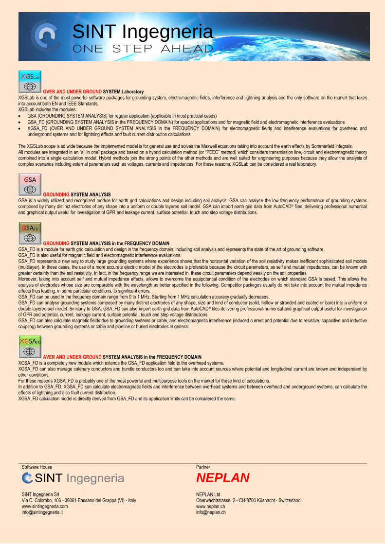
OVER AND UNDER GROUND SYSTEM Laboratory XGSLab is one of the most powerful software packages for grounding system, electromagnetic fields, interference and lightning analysis and the only software on the market that takes into account both EN and IEEE Standards. XGSLab includes the modules:
GSA (GROUNDING SYSTEM ANALYSIS) for regular application (applicable in most practical cases)
GSA_FD (GROUNDING SYSTEM ANALYSIS in the FREQUENCY DOMAIN) for special applications and for magnetic field and electromagnetic interference evaluations
XGSA_FD (OVER AND UNDER GROUND SYSTEM ANALYSIS in the FREQUENCY DOMAIN) for electromagnetic fields and interference evaluations for overhead and underground systems and for lightning effects and fault current distribution calculations
The XGSLab scope is so wide because the implemented model is for general use and solves the Maxwell equations taking into account the earth effects by Sommerfeld integrals. All modules are integrated in an “all in one” package and based on a hybrid calculation method (or “PEEC” method) which considers transmission line, circuit and electromagnetic theory combined into a single calculation model. Hybrid methods join the strong points of the other methods and are well suited for engineering purposes because they allow the analysis of complex scenarios including external parameters such as voltages, currents and impedances. For these reasons, XGSLab can be considered a real laboratory.
GROUNDING SYSTEM ANALYSIS GSA is a widely utilized and recognized module for earth grid calculations and design including soil analysis. GSA can analyse the low frequency performance of grounding systems composed by many distinct electrodes of any shape into a uniform or double layered soil model. GSA can import earth grid data from AutoCAD® files, delivering professional numerical and graphical output useful for investigation of GPR and leakage current, surface potential, touch and step voltage distributions.
GROUNDING SYSTEM ANALYSIS in the FREQUENCY DOMAIN GSA_FD is a module for earth grid calculation and design in the frequency domain, including soil analysis and represents the state of the art of grounding software. GSA_FD is also useful for magnetic field and electromagnetic interference evaluations. GSA_FD represents a new way to study large grounding systems where experience shows that the horizontal variation of the soil resistivity makes inefficient sophisticated soil models (multilayer). In these cases, the use of a more accurate electric model of the electrodes is preferable because the circuit parameters, as self and mutual impedances, can be known with greater certainty than the soil resistivity. In fact, in the frequency range we are interested in, these circuit parameters depend weakly on the soil properties. Moreover, taking into account self and mutual impedance effects, allows to overcome the equipotential condition of the electrodes on which standard GSA is based. This allows the analysis of electrodes whose size are comparable with the wavelength as better specified in the following. Competitor packages usually do not take into account the mutual impedance effects thus leading, in some particular conditions, to significant errors. GSA_FD can be used in the frequency domain range from 0 to 1 MHz. Starting from 1 MHz calculation accuracy gradually decreases. GSA_FD can analyse grounding systems composed by many distinct electrodes of any shape, size and kind of conductor (solid, hollow or stranded and coated or bare) into a uniform or double layered soil model. Similarly to GSA, GSA_FD can also import earth grid data from AutoCAD® files delivering professional numerical and graphical output useful for investigation of GPR and potential, current, leakage current, surface potential, touch and step voltage distributions. GSA_FD can also calculate magnetic fields due to grounding systems or cable, and electromagnetic interference (induced current and potential due to resistive, capacitive and inductive coupling) between grounding systems or cable and pipeline or buried electrodes in general.
AVER AND UNDER GROUND SYSTEM ANALYSIS in the FREQUENCY DOMAIN XGSA_FD is a completely new module which extends the GSA_FD application field to the overhead systems. XGSA_FD can also manage catenary conductors and bundle conductors too and can take into account sources where potential and longitudinal current are known and independent by other conditions. For these reasons XGSA_FD is probably one of the most powerful and multipurpose tools on the market for these kind of calculations. In addition to GSA_FD, XGSA_FD can calculate electromagnetic fields and interference between overhead systems and between overhead and underground systems, can calculate the effects of lightning and also fault current distribution. XGSA_FD calculation model is directly derived from GSA_FD and its application limits can be considered the same.

SINT Ingegneria
Software House
SINT Ingegneria Srl Via C. Colombo, 106 - 36061 Bassano del Grappa (VI) - Italy www.sintingegneria.com [email protected]
Partner
NEPLAN NEPLAN Ltd Oberwachtstrasse, 2 - CH-8700 Küsnacht - Switzerland www.neplan.ch [email protected]
GSA OR GSA_FD? WHY NOT ONLY GSA_FD? WHAT ABOUT XGSA_FD? GSA_FD Vs. GSA The following table summarizes the main assumptions on which GSA_FD and GSA module are based.
Aspects taken into account GSA GSA_FD (S) GSA_FD (S+M)
Resistive coupling Yes Yes Yes
Capacitive coupling No Yes Yes
Self Impedance No Yes Yes
Mutual Impedance No No Yes
GSA_FD can either take into account or ignore the mutual impedance between elements. Thus, in the following the used model will be referred to as GSA_FD (S+M) and GSA_FD (S) respectively. GSA_FD (S+M) requires more computer resources (memory and computing power) than GSA_FD (S) and for this reason the option to account for the mutual impedance can be disabled. The graph in this page represents the application domain of the different models. All models can be adopted in the area below the dotted line whereas both models GSA_FD (S or S+M) can be adopted in the area between the dotted and dashed lines and only model GSA_FD (S+M) can be adopted above the dashed line.
Application domain of GSA and GSA_FD The highlighted area indicates the usual condition at power frequency. Small, medium and large plants gradually require most powerful GSA or GSA_FD versions. The graph is obtained by a parametric analysis with a square meshed test grid made of copper The analysed parameters were grid size “D”, soil resistivity “ρ” and frequency “f”. In their application dominion, the errors made by GSA and GSA_FD (S) in the GPR and touch voltages calculation are lower than 10%. In practice, application limits of the different models can be defined as a function of the wavelength of the electromagnetic field in the earth:
f
3162
where: λ (m) = wavelength ρ (Ωm) = soil resistivity f (Hz) = frequency
The previous graph indicates that GSA can be used if “D < λ/15”. GSA requires also “D < 500 m” because the effects of the dc component of the self impedance. GSA_FD (S) can be used if “D < λ/10”. GSA_FD (S+M) can be used in all cases up to 1 MHz.
Earth Surface Potential - GSA 50 Hz
Earth Surface Potential - GSA_FD (S) 50 Hz
Earth Surface Potential - GSA_FD (S+M) 50 Hz The parametric analysis is carried out assuming the test grid well meshed and energized with a current injected in a corner. If the current is injected in the grid centre, the maximum grid size is double than that mentioned in the previous graph. In other words, “D” indicates the maximum distance between the injection point and the most distant point of the electrode.

SINT Ingegneria
Software House
SINT Ingegneria Srl Via C. Colombo, 106 - 36061 Bassano del Grappa (VI) - Italy www.sintingegneria.com [email protected]
Partner
NEPLAN NEPLAN Ltd Oberwachtstrasse, 2 - CH-8700 Küsnacht - Switzerland www.neplan.ch [email protected]
The figures in this page show the surface potential obtained by applying the three described models to the same grid as well as with the same injected current. The qualitative difference between the results is also evident. In fact, GPR and impedance to earth tend to grow whether GSA, GSA_FD (S) or GSA_FD (S+M) is used. High frequency or low soil resistivity can make this differences even more evident. In brief, in grounding system analysis, at power frequency, GSA can be used in many practical situations but it tends to underestimate the results in case of low resistivity or large grids. GSA_FD (S) tends to underestimate the results in the same condition too and its application area is only a little more extensive than that of GSA. GSA_FD (S) can be applied to grids with size greater than 500 m but only in case of relatively high resistivity soil. GSA_FD (S+M) can be applied in all cases. At high frequency, GSA and GSA_FD (S) can be applied to grids with a maximum size of about some tens of meters. In general, at high frequency GSA_FD (S+M) should be used. In electromagnetic interference analysis, GSA, and GSA_FD (S) and GSA_FD (S+M) can be used respectively for resistive, resistive + capacitive and resistive + capacitive + inductive coupling evaluation. After these conclusions a question could arise: Why not just GSA_FD? GSA requires an easier data entry and fewer computer resources and, whenever applicable, it is the preferred module. GSA_FD requires the same data entry for both (S) and (S+M) models, but the calculations necessary in the latter case are more complex and require more computer resources. If GSA cannot be used and memory and computing power is not a limit, GSA_FD (S+M) is the preferred model. Finally, it is worth noticing that a copper and well meshed test grid has been adopted in the above considerations. Because of the copper cost, in some countries grounding systems are often made of steel. In these cases, the self-impedance values introduce further limits to the application range of the GSA, and GSA_FD may also be necessary for small systems. A similar conclusion applies even if the “well meshed” conditions are not fulfilled. More details about GSA and GSA_FD are provided in the following. XGSA_FD XGSA_FD is based on the same model of GSA_FD (S+M) ant takes into account the same aspects. The application limits of XGSA_FD for underground systems can be assumed as the same of GSA_FD (S+M). The application limits of XGSA_FD for overhead systems can be assumed between 1 Hz and few MHz. XGSA_FD greatly expands the application possibilities of XGSLab and it actually makes a real laboratory for engineering applications and for research. XGSA_FD is an irreplaceable tool when system of conductors is partly overhead and partly underground. This situation is usual in interference analysis (where often the inductor is overhead and the induced is underground) but it is also usual in lightning design. In this last case, XGSA_FD allows to consider in a single model air termination, down conductor and earth termination system, and allows to calculate the lightning current distribution and their effects (potential, magnetic and electric fields). The lightning current can be simulated by using the standard wave form IEC 62305. For instance, the standard first positive stroke T1/T2 = 10/350 µs can be simulated with a 25 kHz current, the first negative stroke 1/200 µs with a 250 kHz current and the subsequent stroke 0.25/100 µs with a 1 MHz current. The effective value of the sinusoidal wave form has to be calculated assuming that the maximum values of pulse and sinusoidal wave form are the same. For instance, the equivalent sinusoidal wave form of a pulse 200 kA - 10/350 µs has an effective value 200/√2 = 141.4 kA. The equivalence between pulse and sinusoidal wave form means that, the maximum values of touch and step voltages or magnetic and electric field of the two wave form are the same.
Standard Lightning Wave Shape MAXWELL EQUATIONS AND SOMMERFELD INTEGRALS XGSLab is based on Maxwell equations and Sommerfeld integrals. Most people know that the electromagnetic field are governed by a set of experimental laws known as Maxwell equations.
James Clerk Maxwell (Edinburgh 1831 – Cambridge 1879) On the other hand, not many people know about the fundamental studies carried out by Sommerfeld. Among other things, Sommerfeld studied the effect of the earth reaction to the electromagnetic field and the rigorous solutions of the half space problem are known as Sommerfeld integrals.
Arnold Johannes Wilhelm Sommerfeld (Konigsberg 1868 – Munich 1951) Without Sommerfeld studies would not have been possible to develop XGSLab.
SINT Ingegneria
Software House
SINT Ingegneria Srl Via C. Colombo, 106 - 36061 Bassano del Grappa (VI) - Italy www.sintingegneria.com [email protected]
Partner
NEPLAN NEPLAN Ltd Oberwachtstrasse, 2 - CH-8700 Küsnacht - Switzerland www.neplan.ch [email protected]
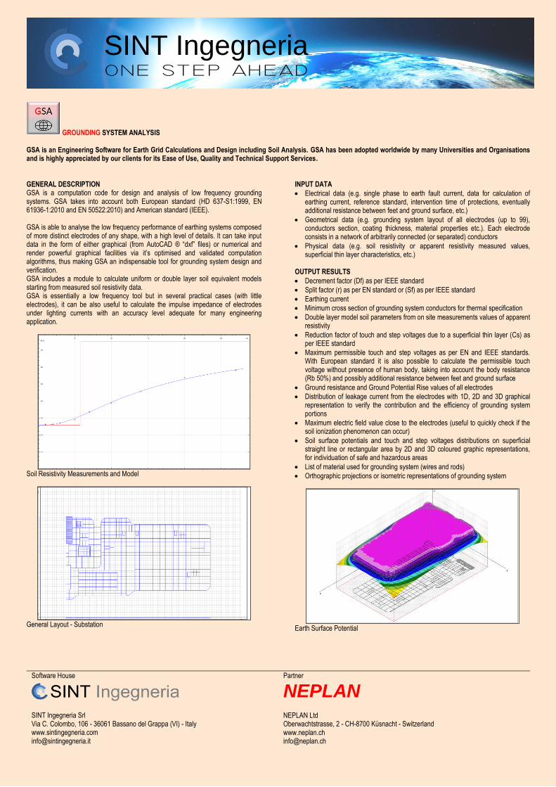
GROUNDING SYSTEM ANALYSIS GSA is an Engineering Software for Earth Grid Calculations and Design including Soil Analysis. GSA has been adopted worldwide by many Universities and Organisations and is highly appreciated by our clients for its Ease of Use, Quality and Technical Support Services. GENERAL DESCRIPTION GSA is a computation code for design and analysis of low frequency grounding systems. GSA takes into account both European standard (HD 637-S1:1999, EN 61936-1:2010 and EN 50522:2010) and American standard (IEEE). GSA is able to analyse the low frequency performance of earthing systems composed of more distinct electrodes of any shape, with a high level of details. It can take input data in the form of either graphical (from AutoCAD ® “dxf” files) or numerical and render powerful graphical facilities via it’s optimised and validated computation algorithms, thus making GSA an indispensable tool for grounding system design and verification. GSA includes a module to calculate uniform or double layer soil equivalent models starting from measured soil resistivity data. GSA is essentially a low frequency tool but in several practical cases (with little electrodes), it can be also useful to calculate the impulse impedance of electrodes under lighting currents with an accuracy level adequate for many engineering application.
Soil Resistivity Measurements and Model
General Layout - Substation
INPUT DATA
Electrical data (e.g. single phase to earth fault current, data for calculation of earthing current, reference standard, intervention time of protections, eventually additional resistance between feet and ground surface, etc.)
Geometrical data (e.g. grounding system layout of all electrodes (up to 99), conductors section, coating thickness, material properties etc.). Each electrode consists in a network of arbitrarily connected (or separated) conductors
Physical data (e.g. soil resistivity or apparent resistivity measured values, superficial thin layer characteristics, etc.)
OUTPUT RESULTS
Decrement factor (Df) as per IEEE standard
Split factor (r) as per EN standard or (Sf) as per IEEE standard
Earthing current
Minimum cross section of grounding system conductors for thermal specification
Double layer model soil parameters from on site measurements values of apparent resistivity
Reduction factor of touch and step voltages due to a superficial thin layer (Cs) as per IEEE standard
Maximum permissible touch and step voltages as per EN and IEEE standards. With European standard it is also possible to calculate the permissible touch voltage without presence of human body, taking into account the body resistance (Rb 50%) and possibly additional resistance between feet and ground surface
Ground resistance and Ground Potential Rise values of all electrodes
Distribution of leakage current from the electrodes with 1D, 2D and 3D graphical representation to verify the contribution and the efficiency of grounding system portions
Maximum electric field value close to the electrodes (useful to quickly check if the soil ionization phenomenon can occur)
Soil surface potentials and touch and step voltages distributions on superficial straight line or rectangular area by 2D and 3D coloured graphic representations, for individuation of safe and hazardous areas
List of material used for grounding system (wires and rods)
Orthographic projections or isometric representations of grounding system
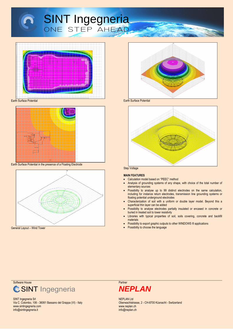
Earth Surface Potential
SINT Ingegneria
Software House
SINT Ingegneria Srl Via C. Colombo, 106 - 36061 Bassano del Grappa (VI) - Italy www.sintingegneria.com [email protected]
Partner
NEPLAN NEPLAN Ltd Oberwachtstrasse, 2 - CH-8700 Küsnacht - Switzerland www.neplan.ch [email protected]
Earth Surface Potential
Earth Surface Potential in the presence of a Floating Electrode
General Layout – Wind Tower
Earth Surface Potential
Step Voltage MAIN FEATURES
Calculation model based on “PEEC” method
Analysis of grounding systems of any shape, with choice of the total number of elementary sources
Possibility to analyse up to 99 distinct electrodes on the same calculation, including for instance return electrodes, transmission line grounding systems or floating potential underground electrodes
Characterization of soil with a uniform or double layer model. Beyond this a superficial thin layer can be added
Possibility to analyse electrodes partially insulated or encased in concrete or buried in treated soil to lower resistivity
Libraries with typical properties of soil, soils covering, concrete and backfill materials
Possibility to export graphic outputs to other WINDOWS ® applications
Possibility to choose the language
SINT Ingegneria
Software House
SINT Ingegneria Srl Via C. Colombo, 106 - 36061 Bassano del Grappa (VI) - Italy www.sintingegneria.com [email protected]
Partner
NEPLAN NEPLAN Ltd Oberwachtstrasse, 2 - CH-8700 Küsnacht - Switzerland www.neplan.ch [email protected]
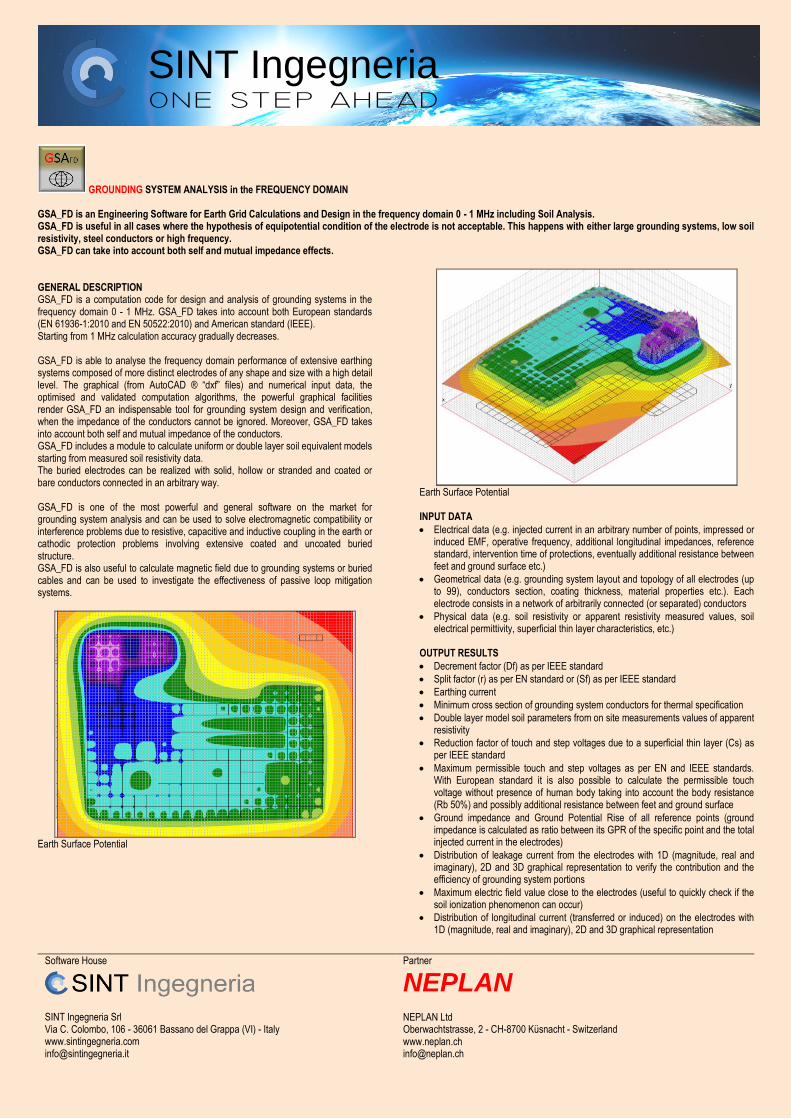
GROUNDING SYSTEM ANALYSIS in the FREQUENCY DOMAIN GSA_FD is an Engineering Software for Earth Grid Calculations and Design in the frequency domain 0 - 1 MHz including Soil Analysis. GSA_FD is useful in all cases where the hypothesis of equipotential condition of the electrode is not acceptable. This happens with either large grounding systems, low soil resistivity, steel conductors or high frequency. GSA_FD can take into account both self and mutual impedance effects. GENERAL DESCRIPTION GSA_FD is a computation code for design and analysis of grounding systems in the frequency domain 0 - 1 MHz. GSA_FD takes into account both European standards (EN 61936-1:2010 and EN 50522:2010) and American standard (IEEE). Starting from 1 MHz calculation accuracy gradually decreases. GSA_FD is able to analyse the frequency domain performance of extensive earthing systems composed of more distinct electrodes of any shape and size with a high detail level. The graphical (from AutoCAD ® “dxf” files) and numerical input data, the optimised and validated computation algorithms, the powerful graphical facilities render GSA_FD an indispensable tool for grounding system design and verification, when the impedance of the conductors cannot be ignored. Moreover, GSA_FD takes into account both self and mutual impedance of the conductors. GSA_FD includes a module to calculate uniform or double layer soil equivalent models starting from measured soil resistivity data. The buried electrodes can be realized with solid, hollow or stranded and coated or bare conductors connected in an arbitrary way. GSA_FD is one of the most powerful and general software on the market for grounding system analysis and can be used to solve electromagnetic compatibility or interference problems due to resistive, capacitive and inductive coupling in the earth or cathodic protection problems involving extensive coated and uncoated buried structure. GSA_FD is also useful to calculate magnetic field due to grounding systems or buried cables and can be used to investigate the effectiveness of passive loop mitigation systems.
Earth Surface Potential
Earth Surface Potential INPUT DATA
Electrical data (e.g. injected current in an arbitrary number of points, impressed or induced EMF, operative frequency, additional longitudinal impedances, reference standard, intervention time of protections, eventually additional resistance between feet and ground surface etc.)
Geometrical data (e.g. grounding system layout and topology of all electrodes (up to 99), conductors section, coating thickness, material properties etc.). Each electrode consists in a network of arbitrarily connected (or separated) conductors
Physical data (e.g. soil resistivity or apparent resistivity measured values, soil electrical permittivity, superficial thin layer characteristics, etc.)
OUTPUT RESULTS
Decrement factor (Df) as per IEEE standard
Split factor (r) as per EN standard or (Sf) as per IEEE standard
Earthing current
Minimum cross section of grounding system conductors for thermal specification
Double layer model soil parameters from on site measurements values of apparent resistivity
Reduction factor of touch and step voltages due to a superficial thin layer (Cs) as per IEEE standard
Maximum permissible touch and step voltages as per EN and IEEE standards. With European standard it is also possible to calculate the permissible touch voltage without presence of human body taking into account the body resistance (Rb 50%) and possibly additional resistance between feet and ground surface
Ground impedance and Ground Potential Rise of all reference points (ground impedance is calculated as ratio between its GPR of the specific point and the total injected current in the electrodes)
Distribution of leakage current from the electrodes with 1D (magnitude, real and imaginary), 2D and 3D graphical representation to verify the contribution and the efficiency of grounding system portions
Maximum electric field value close to the electrodes (useful to quickly check if the soil ionization phenomenon can occur)
Distribution of longitudinal current (transferred or induced) on the electrodes with 1D (magnitude, real and imaginary), 2D and 3D graphical representation

SINT Ingegneria
Software House
SINT Ingegneria Srl Via C. Colombo, 106 - 36061 Bassano del Grappa (VI) - Italy www.sintingegneria.com [email protected]
Partner
NEPLAN NEPLAN Ltd Oberwachtstrasse, 2 - CH-8700 Küsnacht - Switzerland www.neplan.ch [email protected]
Distribution of potential (transferred or induced) on the electrodes with 1D (magnitude, real and imaginary), 2D and 3D graphical representation
Distribution of electromotive force on the electrodes with 1D (magnitude, real and imaginary), 2D and 3D graphical representation
Soil surface potentials and touch and step voltages distributions on superficial straight line or rectangular area by 2D and 3D coloured graphic representations, for individuation of safe and hazardous areas
Magnetic field distributions on horizontal straight line or rectangular area with 1D, 2D and 3D coloured graphic representations, for individuation of safe and hazardous areas
List of material used for grounding system (wires and rods)
Orthographic projections or isometric representations of grounding system
Touch Voltages
Step Voltages
Magnetic Field
Magnetic Field
Earth Surface Potential - GSA_FD (S+M) 50 Hz

SINT Ingegneria
Software House
SINT Ingegneria Srl Via C. Colombo, 106 - 36061 Bassano del Grappa (VI) - Italy www.sintingegneria.com [email protected]
Partner
NEPLAN NEPLAN Ltd Oberwachtstrasse, 2 - CH-8700 Küsnacht - Switzerland www.neplan.ch [email protected]
Earth Surface Potential - GSA_FD (S+M) 500 Hz
Earth Surface Potential - GSA_FD (S+M) 5 kHz
Earth Surface Potential - GSA_FD (S+M) 50 kHz
Magnetic Field Mitigation with a Passive Loop
Magnetic Field Mitigation with a Passive Loop MAIN FEATURES
Calculation model based on “PEEC” method
Analysis of grounding systems of any shape, with choice of the total number of elementary sources
Possibility to take into account or exclude the mutual impedance between elements
Possibility to analyse up to 99 distinct electrodes on the same calculation, including for instance return electrodes, transmission line grounding systems or floating potential underground electrodes
Automatic recognition of the connections between conductors
Characterization of soil with a uniform or double layer model. Beyond this, a superficial thin layer can be added
Possibility to analyse electrodes partially insulated or encased in concrete or buried in treated soil to lower resistivity
Libraries with typical properties of soil, soils covering, conductors and insulating materials
Possibility to export graphic outputs to other WINDOWS ® applications
Possibility to choose the language

SINT Ingegneria
Software House
SINT Ingegneria Srl Via C. Colombo, 106 - 36061 Bassano del Grappa (VI) - Italy www.sintingegneria.com [email protected]
Partner
NEPLAN NEPLAN Ltd Oberwachtstrasse, 2 - CH-8700 Küsnacht - Switzerland www.neplan.ch [email protected]
OVER AND UNDER GROUND SYSTEM ANALYSIS in the FREQUENCY DOMAIN XGSA_FD is a multipurpose Engineering Software for Grounding Systems, Electromagnetic Field and Interference Analysis and Fault Current Distribution in the frequency domain 1 Hz - 1 MHz including Soil Analysis. XGSA_FD uses a model similar to GSA_FD (S+M) and then it can take into account both self and mutual impedance effects. Moreover XGSA_FD can take into account overhead systems and also sources where potential and longitudinal current are known and independent by other conditions. GENERAL DESCRIPTION XGSA_FD is a computation code for grounding systems, electromagnetic field and interference analysis in the frequency domain 1 Hz - 1 MHz. Starting from 1 MHz calculation accuracy gradually decreases. XGSA_FD uses a model similar to GSA_FD (S+M) and referring to underground electrodes the two models can be considered the same. XGSA_FD extends the GSA_FD application field to the overhead systems and can manage straight or catenary spans of single or bundle conductors (solid, hollow or stranded and coated or bare), and can take into account sources where potential and longitudinal current are known and independent by other conditions. The underground or overhead conductors can be connected in an arbitrary way. XGSA_FD is a multipurpose software and its use is not limited to specific cases. XGSA_FD application field includes grounding system analysis but is oriented in particular way to solve electromagnetic compatibility or interference problems due to resistive, capacitive and inductive coupling in air or in the earth. XGSA_FD can calculate the effects of lightning and also fault current distribution. XGSA_FD is also useful to calculate magnetic and electric field due to underground or overhead electrodes (grounding systems, buried cables, overhead power lines) and can be used to investigate the effectiveness of passive loop mitigation systems.
Interference Layout between overhead power line (blue) and buried pipeline (green) INPUT DATA As for GSA_FD and moreover:
Additional Electrical data (e.g. conductors with potential and longitudinal current known and independent by other conditions, additional longitudinal and transverse impedances, etc.)
Additional Geometrical data (e.g. overhead system layout and topology of all electrodes (up to 99), catenary constant, bundle diameter, bundle conductors number, conductor conductors section, coating thickness, material properties etc.). Each electrode consists in a network of arbitrarily connected (or separated) conductors
OUTPUT RESULTS As for GSA_FD and moreover:
Distribution of leakage current, longitudinal current, potential and electromotive force on the overhead electrodes with 1D (magnitude, real and imaginary), 2D and 3D graphical representation
Magnetic field distributions on arbitrarily oriented straight line or horizontal or vertical rectangular area with 1D, 2D and 3D coloured graphic representations, for individuation of safe and hazardous areas
Electric field distributions on arbitrarily oriented straight line or horizontal or vertical rectangular area with 1D, 2D and 3D coloured graphic representations, for individuation of safe and hazardous areas
Magnetic Field 1 m above the soil surface
Magnetic Field 1 m above the soil surface
SINT Ingegneria
Software House
SINT Ingegneria Srl Via C. Colombo, 106 - 36061 Bassano del Grappa (VI) - Italy www.sintingegneria.com [email protected]
Partner
NEPLAN NEPLAN Ltd Oberwachtstrasse, 2 - CH-8700 Küsnacht - Switzerland www.neplan.ch [email protected]
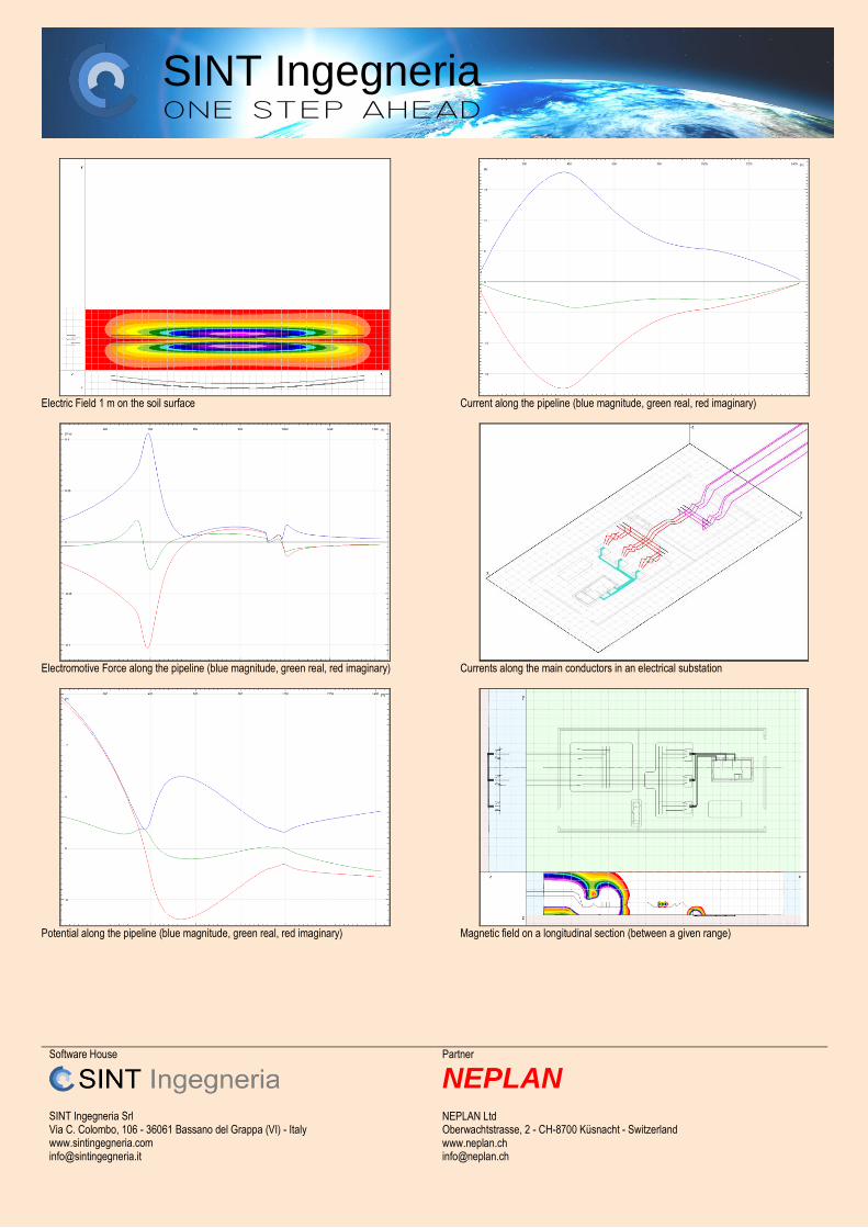
Electric Field 1 m on the soil surface
Electromotive Force along the pipeline (blue magnitude, green real, red imaginary)
Potential along the pipeline (blue magnitude, green real, red imaginary)
Current along the pipeline (blue magnitude, green real, red imaginary)
Currents along the main conductors in an electrical substation
Magnetic field on a longitudinal section (between a given range)

SINT Ingegneria
Software House
SINT Ingegneria Srl Via C. Colombo, 106 - 36061 Bassano del Grappa (VI) - Italy www.sintingegneria.com [email protected]
Partner
NEPLAN NEPLAN Ltd Oberwachtstrasse, 2 - CH-8700 Küsnacht - Switzerland www.neplan.ch [email protected]
Lightning stroke on a LPS
Lightning current distribution on LPS and Grounding System - 1 MHz
Earth Surface Potential - 1 MHz
Magnetic Field on the soil surface - 1 MHz
Electric Field on the soil surface - 1 MHz MAIN FEATURES As for GSA_FD and moreover:
Analysis of overhead and underground systems of any shape, with choice of the total number of elementary sources
Possibility to analyse up to 99 distinct overhead and underground electrodes on the same calculation
Possibility to take into account sources where potential and longitudinal current are known and independent by other conditions
Possibility to analyse overhead straight or catenary spans of single or bundle conductors
Unlike GSA_FD, with XGSA_FD is not possible to exclude the mutual impedance effects between elements.