Singular Configurations of Wrist-Partitioned 6R...
15
Singular Configurations of Wrist-Partitioned 6R Serial Robots: a Geometric Perspective for Users M.J.D. HAYES 1,2 , M.L. HUSTY 3 and P.J. ZSOMBOR-MURRAY 4 1 Mechanical & Aerospace Engineering, Carleton University, Canada 2 Institut f¨ ur Automation, Montanuniversit¨ at Leoben, Austria 3 Institut f¨ ur Technische Mathematik, Geometrie und Bauinformatik, Universit¨ at Innsbruck, Austria 4 Centre for Intelligent Machines, McGill University, Canada April 2, 2003 Abstract In this paper the singular configurations of wrist-partitioned 6R serial robots in gen- eral, and the KUKA KR-15/2 industrial robot in particular, are analytically described and classified. While the results are not new, the insight provided by the geometric analysis for users of such robots is. Examining the problem in the joint axis parameter space, it is shown that when the end-effector reference point is taken to be the wrist centre the determinant of the associated Jacobian matrix splits into four factors, three of which can vanish. Two of the three potentially vanishing factors give a complete de- scription of the positioning singularities and the remaining one a complete description of the orientation singularities, in turn providing a classification scheme. Configurations Singuli` eres des Robots S´ eriels `a Poignet Sph´ erique et Six Couples Rot¨oides: une Perspective G´ eom´ etrique pour les Utilisateurs R´ esum´ e Dans cet article les configurations singuli´ eres des robots s´ eriels `a poignet sph´ erique et six couples rot¨oides en g´ en´ eral, et celle du robot industriel KUKA KR-15/2 en particulier, sont analytiquement d´ ecrites et classifi´ ees. Bien que les r´ esultats ne soient pas nouveaux, la perspective fournie par l’analyse g´ eom´ etrique pour des utilisateurs de tels robots l’est. En examinant le probl` eme dans l’espace commun de param` etre d’axe, on montre que quand le point de r´ ef´ erence terminal est pris comme ´ etant le centre du poignet le d´ eterminant de la matrice associ´ ee du Jacobian se divise en quatre facteurs, dont trois peuvent dispara ˆ itre. Deux des trois facteurs qui peuvent potentiellement dispara ˆ itre donnent une description compl` ete des singularit´ es de positionnement et les autres une description compl` ete des singularit´ es d’orientation, fournissant ainsi une m´ ethode de classification.
-
Upload
vuongquynh -
Category
Documents
-
view
218 -
download
2
Transcript of Singular Configurations of Wrist-Partitioned 6R...

Singular Configurations of Wrist-Partitioned 6R SerialRobots: a Geometric Perspective for Users
M.J.D. HAYES1,2, M.L. HUSTY3 and P.J. ZSOMBOR-MURRAY4
1Mechanical & Aerospace Engineering, Carleton University, Canada2Institut fur Automation, Montanuniversitat Leoben, Austria
3Institut fur Technische Mathematik, Geometrie und Bauinformatik,Universitat Innsbruck, Austria
4Centre for Intelligent Machines, McGill University, Canada
April 2, 2003
AbstractIn this paper the singular configurations of wrist-partitioned 6R serial robots in gen-
eral, and the KUKA KR-15/2 industrial robot in particular, are analytically describedand classified. While the results are not new, the insight provided by the geometricanalysis for users of such robots is. Examining the problem in the joint axis parameterspace, it is shown that when the end-effector reference point is taken to be the wristcentre the determinant of the associated Jacobian matrix splits into four factors, threeof which can vanish. Two of the three potentially vanishing factors give a complete de-scription of the positioning singularities and the remaining one a complete descriptionof the orientation singularities, in turn providing a classification scheme.
Configurations Singulieres des Robots Seriels a PoignetSpherique et Six Couples Rotoides: une Perspective
Geometrique pour les Utilisateurs
ResumeDans cet article les configurations singulieres des robots seriels a poignet spheriqueet six couples rotoides en general, et celle du robot industriel KUKA KR-15/2 enparticulier, sont analytiquement decrites et classifiees. Bien que les resultats ne soientpas nouveaux, la perspective fournie par l’analyse geometrique pour des utilisateurs detels robots l’est. En examinant le probleme dans l’espace commun de parametre d’axe,on montre que quand le point de reference terminal est pris comme etant le centre dupoignet le determinant de la matrice associee du Jacobian se divise en quatre facteurs,dont trois peuvent disparaitre. Deux des trois facteurs qui peuvent potentiellementdisparaitre donnent une description complete des singularites de positionnement et lesautres une description complete des singularites d’orientation, fournissant ainsi unemethode de classification.

1 Introduction
The singularities of wrist-partitioned six-revolute (6R) axis serial robots have already beenthoroughly investigated and classified. The aim of this paper is to describe certain resultsin a readily accessible way using elementary concepts from linear algebra and geometry. 6Rserial robot singularities occur at configurations corresponding to singularities of the 6 × 6Jacobian matrix relating the robot’s joint rates to the end-effector (EE) Cartesian velocities.The formulation of the Jacobian found in this paper summarises and builds upon materialfound in text books such as [1, 2, 3].
Singular configurations of three degree-of-freedom (DOF) positioning robots, also calledregional manipulators, are analysed in terms of Cartesian singularity surfaces in [4]. 3R po-sitioning manipulator singularities are enumerated and classified using the notion of genericmanipulator singularities in [5]. The orientation of the EE in a wrist-partitioned manipula-tor is usually adjusted by its spherical wrist. The nature of wrist orienting singularities areexplained in the context of the hyperbolic normal form in [6].
The concept of removable singularities has been a major research area. This notionstates that if a singularity occurs on the path between two configurations, it may, undercertain conditons, be removed by slightly altering the path. Removable singularities occurin robots possessing three, four, and five DOF, whereas singularities associated with six DOFrobots are nonremovable. A representative method for removing singularities from the threepositioning joints of a six DOF PUMA is investigated in [7]. Classification and enumerationof 5R robots possessing nonremovable singularities is presented in [8].
Singularities in redundantly actuated manipulators can lead to self motions. These are,perhaps, the most insidious because the EE can move when the manipulator should be sta-tionary. A recent investigation into particular parallel platform architectures, one intendedfor use as a flight simulator, have self motions in every configuration in its workspace [9].Additional work has been directed towards determining conditions for avoidability and un-avoidability in serial redundant robots, see [10].
Hunt [11] revived a geometric entity called the cylindroid, which fell from use duringthe middle part of the twentieth century. The cylindroid is a ruled surface generated by theresultant wrench of two conjugate screws of equal pitch. It is well known that the columns ofthe Jacobian are Plucker line, or screw coordinates of the six revolute axes, see [12]. Certainproperties of the cylindroid regarded in the context of screw theory provide an algebraic-geometric framework of great use in the rank analysis of robot manipulator Jacobians [13].For instance, the set of all singular configurations of serial six DOF manipulators is describedusing Lie algebra properties of the screw space in [14].
There are many other important contributions regarding general 6R singularities con-tained in the literature. Some representative examples are [15, 16, 17, 18, 19]. The list isby no means exhaustive, but is included to serve as a guideline for further study by thereader so inclined. The literature is well known among kinematicians, geometricians, androbotics researchers. Despite this fact, operating manuals for industrial models give eitheran insignificant treatment of the subject, or none at all, see for instance [20, 21, 22]. What istruly unfortunate is that it appears most users of 6R robots are generally not well acquainted
2

Figure 1: General 6R wrist-partitioned architecture.
with the literature, rather only the operating manuals of their specific robot.When the robot comes to a sudden, crashing halt the operator is often left mystified as
to why. Courses offered by robot manufacturers are a partial remedy in that cautionarylessons are given: warning the operator not to programme positions too near the work spaceboundary; avoid alignment of some axes; exercise caution in regions close to singularities andmonitor for rapid increases in joint rates. However, the learning curve to the understanding ofthe causes is frustratingly long and steep. Additionally, while the English-language literatureexamined gives a complete and exact classification, it requires a very advanced level ofmathematical and geometric knowledge and experience. What is required, from a robotusers point of view, is a focused geometric interpretation of how the singularities arise, giventhe structure of the associated Jacobian. This gives the motivation to present the followinganalysis.
1.1 Kuka KR-15/2 Description
A wrist-partitioned, or decoupled manipulator is defined as one whose wrist axes (the lastthree axes) intersect in a common point, see Figure 1. The wrist is also spherical becausewhen the intersection point, C, of the axes is fixed then all points on the wrist move onspheres centred at C. It is also said to be partitioned, or decoupled because the positioningand orienting problems can be considered separately. That is, when point C is the end-effector (EE) reference point, arbitrary displacements can be thought of as the translationof point C combined with the orientation of the EE reference frame, whose origin is C.
The KUKA KR-15/2 is illustrated in Figure 2, showing its six axes together with its base,{B}, and EE, {E}, reference frames. Coordinate reference frames are attached to each linkusing the Denavit-Hartenberg procedure [23]. Thus, the EE can be brought to any desiredposition and orientation, within the workspace of the robot, by changing the joint anglesθi about their respective joint rotation axes ei, where i ∈ {1, 2, . . . , 6} (see Figure 1). Thepoint of intersection of axes 4, 5, and 6, point C in Figures 1 and 2, is considered as the EEreference point.
3

Figure 2: The six axes, base, {B}, and EE, {E}, reference frames of a KR-15/2.
2 The Jacobian
The Jacobian is a time-varying linear transformation that relates the Cartesian velocities ofthe EE to the time rate of change of the joint angles. It allows for the relationship betweenthe two vectors to be expressed as
v = Jθ, (1)
where the six joint rates are given by
θ =[
θ1 θ2 . . . θ6
]T. (2)
The velocity vector is
v =
[wc
], (3)
with
w =
ωx
ωy
ωz
, c =
cx
cy
cz
, (4)
4

where w is the angular velocity vector of the EE reference frame and c the linear velocityvector of C all relative to the fixed base frame.
It is well known that the determinant of the Jacobian of a six-axis robot is invariant undera change of the EE reference point [2, 3]. It will prove useful in the analysis to consider C asthis point. To determine the Jacobian matrix, we require the direction vectors of the jointaxes, ei. We additionally need the position vectors, ri, of point C with respect to the ithjoint axis coordinate frame origin. Both ei and ri must be expressed in terms of the basecoordinate reference system.
Moreover, we will require the moments of the lines of the joint axes relative to the originof the base frame, shown in Figure 2. The moment vector of a line about point C, indicatedby mC , is defined as the cross-product of the position vector of a point on the line, emanatingfrom point C, with the line-bound direction vector of the line itself. If the position vector isr and the line-bound vector is e then the moment vector with respect to C is defined as
mC = r× e. (5)
It is convenient to instead define the ri as the vector from the origin of the ith axisreference frame, indicated by Oi, to point C, rather than as pointing from C to Oi. In thedefinitions below, the order of the cross-product is reversed to agree with the change of senseof the ri. It is important to note that, although we will focus our attention in particularon the KUKA KR-15/2, the only condition on the following analysis is that the wrist bepartitioned.
2.1 Positioning Problem
For a general wrist-partitioned 6R manipulator, the motion of the EE can be decoupledinto distinct components: the positioning of point C and the orientation of the EE [4, 15].The location of point C in the base reference frame is clearly independent of joint anglesθ4, θ5 and θ6. In this sense, the EE reference point can be brought to different positionsonly by changing the angles about axes 1, 2 and 3. Therefore, the linear velocity of point Cdepends only on the time rate of change of the joint angles θ1, θ2 and θ3. The linear velocitycomponents contributed by each angular joint velocity must be perpendicular to the planesspanned by corresponding pairs of vectors of angular joint velocities and the ri, which maybe expressed as θiei × ri = ωi × ri. We can write:
c = θ1e1 × r1 + θ2e2 × r2 + θ3e3 × r3, (6)
again, ri being the position vector of C with respect to Oi, and ei the direction vector of theaxes, both expressed in coordinates of the base frame.
2.2 Orienting Problem
The angular velocity vector, w, of the EE reference frame whose origin is on C can be writtenas the vector sum of the contributions of the angular velocities of the individual joints:
w = ω1 + ω2 + . . . + ω6 = θ1e1 + θ2e2 + . . . + θ6e6. (7)
5
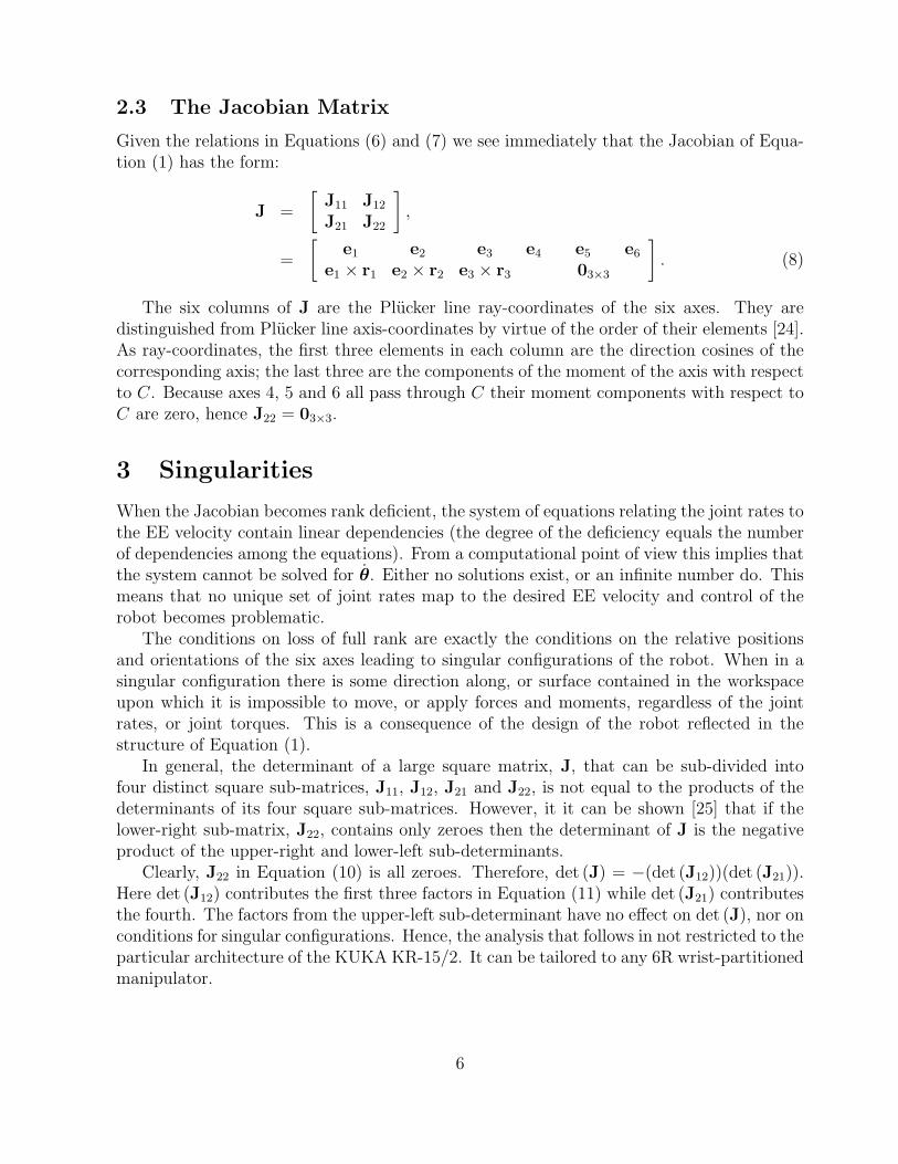
2.3 The Jacobian Matrix
Given the relations in Equations (6) and (7) we see immediately that the Jacobian of Equa-tion (1) has the form:
J =
[J11 J12
J21 J22
],
=
[e1 e2 e3 e4 e5 e6
e1 × r1 e2 × r2 e3 × r3 03×3
]. (8)
The six columns of J are the Plucker line ray-coordinates of the six axes. They aredistinguished from Plucker line axis-coordinates by virtue of the order of their elements [24].As ray-coordinates, the first three elements in each column are the direction cosines of thecorresponding axis; the last three are the components of the moment of the axis with respectto C. Because axes 4, 5 and 6 all pass through C their moment components with respect toC are zero, hence J22 = 03×3.
3 Singularities
When the Jacobian becomes rank deficient, the system of equations relating the joint rates tothe EE velocity contain linear dependencies (the degree of the deficiency equals the numberof dependencies among the equations). From a computational point of view this implies thatthe system cannot be solved for θ. Either no solutions exist, or an infinite number do. Thismeans that no unique set of joint rates map to the desired EE velocity and control of therobot becomes problematic.
The conditions on loss of full rank are exactly the conditions on the relative positionsand orientations of the six axes leading to singular configurations of the robot. When in asingular configuration there is some direction along, or surface contained in the workspaceupon which it is impossible to move, or apply forces and moments, regardless of the jointrates, or joint torques. This is a consequence of the design of the robot reflected in thestructure of Equation (1).
In general, the determinant of a large square matrix, J, that can be sub-divided intofour distinct square sub-matrices, J11, J12, J21 and J22, is not equal to the products of thedeterminants of its four square sub-matrices. However, it it can be shown [25] that if thelower-right sub-matrix, J22, contains only zeroes then the determinant of J is the negativeproduct of the upper-right and lower-left sub-determinants.
Clearly, J22 in Equation (10) is all zeroes. Therefore, det (J) = −(det (J12))(det (J21)).Here det (J12) contributes the first three factors in Equation (11) while det (J21) contributesthe fourth. The factors from the upper-left sub-determinant have no effect on det (J), nor onconditions for singular configurations. Hence, the analysis that follows in not restricted to theparticular architecture of the KUKA KR-15/2. It can be tailored to any 6R wrist-partitionedmanipulator.
6
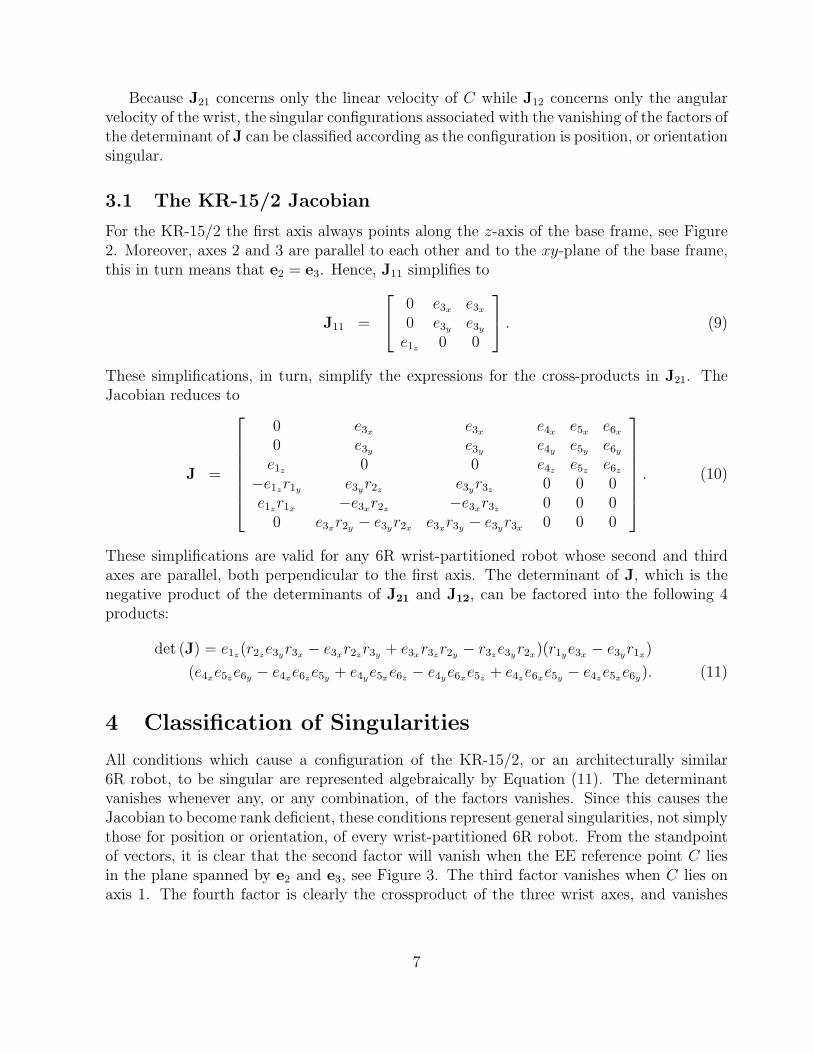
Because J21 concerns only the linear velocity of C while J12 concerns only the angularvelocity of the wrist, the singular configurations associated with the vanishing of the factors ofthe determinant of J can be classified according as the configuration is position, or orientationsingular.
3.1 The KR-15/2 Jacobian
For the KR-15/2 the first axis always points along the z-axis of the base frame, see Figure2. Moreover, axes 2 and 3 are parallel to each other and to the xy-plane of the base frame,this in turn means that e2 = e3. Hence, J11 simplifies to
J11 =
0 e3x e3x
0 e3y e3y
e1z 0 0
. (9)
These simplifications, in turn, simplify the expressions for the cross-products in J21. TheJacobian reduces to
J =
0 e3x e3x e4x e5x e6x
0 e3y e3y e4y e5y e6y
e1z 0 0 e4z e5z e6z
−e1zr1y e3yr2z e3yr3z 0 0 0e1zr1x −e3xr2z −e3xr3z 0 0 0
0 e3xr2y − e3yr2x e3xr3y − e3yr3x 0 0 0
. (10)
These simplifications are valid for any 6R wrist-partitioned robot whose second and thirdaxes are parallel, both perpendicular to the first axis. The determinant of J, which is thenegative product of the determinants of J21 and J12, can be factored into the following 4products:
det (J) = e1z(r2ze3yr3x − e3xr2zr3y + e3xr3zr2y − r3ze3yr2x)(r1ye3x − e3yr1x)
(e4xe5ze6y − e4xe6ze5y + e4ye5xe6z − e4ye6xe5z + e4ze6xe5y − e4ze5xe6y). (11)
4 Classification of Singularities
All conditions which cause a configuration of the KR-15/2, or an architecturally similar6R robot, to be singular are represented algebraically by Equation (11). The determinantvanishes whenever any, or any combination, of the factors vanishes. Since this causes theJacobian to become rank deficient, these conditions represent general singularities, not simplythose for position or orientation, of every wrist-partitioned 6R robot. From the standpointof vectors, it is clear that the second factor will vanish when the EE reference point C liesin the plane spanned by e2 and e3, see Figure 3. The third factor vanishes when C lies onaxis 1. The fourth factor is clearly the crossproduct of the three wrist axes, and vanishes
7

whenever any pair becomes collinear. Still, we believe insight is gained by considering thesingularities from the perspective of the basis of the vectorspace comprising the componentsof the ei and ri. We will now discuss the geometric implications.
4.1 Case 1
The first factor is e1z . Since this quantity represents the direction of the first joint axis itcan never be identically zero. Indeed, the components of the direction vectors of the jointaxes are direction cosines and thus unit vectors. We may safely set e1z = 1 and rewrite thedeterminant as the product of just three factors:
det (J) = (r2ze3yr3x − e3xr2zr3y + e3xr3zr2y − r3ze3yr2x)(r1ye3x − e3yr1x)
(e4xe5ze6y − e4xe6ze5y + e4ye5xe6z − e4ye6xe5z + e4ze6xe5y − e4ze5xe6y). (12)
Should any of these factors vanish the associated configuration of the robot is singular,i.e. at least one degree of freedom is lost. In the following three subsections the conditionsthat cause each of the three factors to vanish are examined from the perspective of theparameter space geometry. The corresponding conditions in the Cartesian space of the basecoordinate reference system are also discussed.
4.2 Case 2: Elbow Singularity
If the first factor in Equation (12) is equal to 0 the corresponding singular configuration iscalled an elbow singularity. Equation (13) involves products of the elements of e3, r2 and r3.
r2ze3yr3x − e3xr2zr3y + e3xr3zr2y − r3ze3yr2x = 0. (13)
In the coordinate space with these parameters as basis vectors, Equation (13) is an eight-dimensional third-order surface; (e3x , e3y , r2x , r2y , r2z , r3x , r3y , r3z) being the parameters.
Neither the relative layout of the three vectors nor their magnitudes are affected byrotations about axis 1, so we may consider axes 2 and 3 only when they are parallel tothe yz-plane. We then consider the intersection of the surface with the plane e3x = 0. Inthis plane the x-components of the axis direction vectors are 0. Thus, terms containing e3x
vanish and the factor reduces to a five-dimensional cubic curve (the curve of intersection ofthe plane and the parameter singularity surface):
r2ze3yr3x − r3ze3yr2x = 0. (14)
The remaining two terms contain only e3y because axes 2 and 3 are always parallel to the xy-plane and never have a z-direction component. Since the direction vector can never vanish,e3 can be normalized, which leaves the condition:
r2zr3x = r3zr2x , or r2z : r3z = r2x : r3x . (15)
8

Figure 3: Staubli RX series elbow singular configuration.
After inspecting Equation (15) it is clear the condition is satisfied whenever r2 and r3
are aligned on the z- or x-axes, respectively. But, in general it is satisfied whenever r2 andr3 are aligned. Recall that ri = c−Oi, which means we can write Equation (15) in terms ofthe angle between the z- and y-components for each of r2 and r3, i.e., φ1 and φ2:
‖r3‖ cos φ3 : ‖r2‖ cos φ2 = ‖r3‖ sin φ3 : ‖r2‖ sin φ2. (16)
Equation (16) can only be satisfied when φ3 = ±φ2 (mod π), or when the magnitude ofeither r2 or r3 vanishes. The latter requires that point C be located on the origin of thecoordinate reference frame of either joint 2 or 3, but this is physically impossible for the KR-15/2, and most other 6R wrist-partitioned robots, due to link interference. Additionally, thecase where φ3 = φ2± π is precluded by joint limits and interference. This type of positionalsingularity is therefore restricted to the condition that φ3 = ±φ2.
Figure 4: Two KUKA KR-15/2 elbow singular configurations.
9
In summary, the elbow singular configurations occur whenever point C lies in the planespanned by axes 2 and 3. For the KUKA KR-15/2, this can only occur when O2, O3 and Care distinct and collinear. When the robot is in an elbow singular configuration changes inthe angles of joints 2 and 3, ∆θ2 and ∆θ3, can produce motions only in the direction normalto the plane Π23 containing e2 and e3. No motions of C in Π23 parallel to e2 and e3 arepossible. Two elbow singular configurations are shown in Figure 4.
Owing to the construction of the KR-15/2 the elbow singular sub-space comprises aportion of the surface of a fixed torus centred at the origin of the base reference frame.In general, this is true for all wrist-partitioned robots. The torus shape parameters aredependent on the link lengths and joint offset between axis 1 and 2. For robots designedsuch that axes 1 and 2 intersect, such as the Staubli RX series, and the Kawasaki JS-10, thetorus degenerates to a double sphere.
Clearly, the elbow singularity surface represents the limits of the robot workspace. Asthe working envelope is easily visualised, elbow singular configurations should be easilyanticipated. They may be avoided by keeping the EE at a safe distance from its limits.
4.3 Case 3: Shoulder Singularity
If the second factor in Equation (12) vanishes the configuration is said to be shoulder singular,see Figure 5. The following arguments illustrate why.
r1ye3x − e3yr1x = 0. (17)
Equation (17) may be viewed as a four-dimensional quadric surface in the coordinate spacewhose basis are the parameters (e3x , e3y , r1x , r1y). It can vanish under three circumstances.
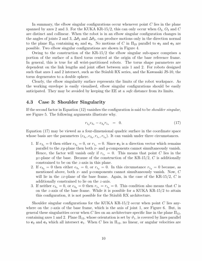
1. If e3x = 0 then either e3y = 0, or r1x = 0. Since e3 is a direction vector which remainsparallel to the xy-plane then both x- and y-components cannot simultaneously vanish.Hence, the factor will vanish only if r1x = 0. This means that point C lies in theyz-plane of the base. Because of the construction of the KR-15/2, C is additionallyconstrained to be on the z-axis in this plane.
2. If e3y = 0 then either e3x = 0, or r1y = 0. In this circumstance r1y = 0 because, asmentioned above, both x- and y-components cannot simultaneously vanish. Now, Cwill lie in the zx-plane of the base frame. Again, in the case of the KR-15/2, C isadditionally constrained to lie on the z-axis.
3. If neither e3x = 0, or e3y = 0 then r1x = r1y = 0. This condition also means that C ison the z-axis of the base frame. While it is possible for a KUKA KR-15/2 to attainthis configuration, it is not possible for the Staubli RX architecture.
Shoulder singular configurations for the KUKA KR-15/2 occur when point C lies any-where on the z-axis of the base frame, which is the axis of joint 1, see Figure 6. But, ingeneral these singularities occur when C lies on an architecture specific line in the plane Π12,containing axes 1 and 2. Plane Π12, whose orientation is set by ϑ1, is covered by lines parallelto e2 and e3 which all intersect e1. When C lies in Π12, no linear, or angular velocities are
10

Figure 5: A Staubli RX series shoulder singular configuration.
possible in the directions parallel to e2 and e3, although it can move on a line parallel toe1, the axis of the first joint. Point C can have any location along this singularity line,and the line itself can be rotated about axis 1. Therefore, the shoulder singularities occupythe surface of a right-circular cylinder of radius r, whose central axis lies on axis 1. Forthe KR-15/2, r = 0. Because the shoulder singularities are contained within the reachableworkspace, they are more difficult to anticipate than elbow singularities.
Figure 6: Two KUKA KR-15/2 shoulder singular configurations.
11

4.4 Case 4: Wrist Singularity
The last case concerns the third factor in Equation (12). This condition depends only on thedirection cosines of the three wrist axes 4, 5 and 6. For this reason they are termed wristsingularities, and are pure orienting singulatities in contrast to the positioning singularitiesof the elbow and shoulder, which depend on the position of C.
Equation (18) represents the determinant of J21. It may be thought of as a nine-dimensional third-order surface in the coordinate space of the nine components of e4, e5
and e6.
e4xe5ze6y − e4xe6ze5y + e4ye5xe6z − e4ye6xe5z + e4ze6xe5y − e4ze5xe6y = 0. (18)
For orientations of the wrist axes the location of the wrist centre, C, is arbitrary. Let itbe located on the origin of the fixed base frame. Moreover, this singularity condition dependson the relative orientation of axes 4, 5 and 6, so we can consider one to be fixed relative tothe others and the base frame. In this way we will consider the intersections of the cubicsurface with the nine individual coordinate planes. Here we will examine e5:
1. e5 =
100
: Equation (18) reduces to
e4ye6z − e4ze6y = 0. (19)
2. e5 =
010
: Equation (18) reduces to
e4ze6x − e4xe6z = 0. (20)
3. e5 =
001
: Equation (18) reduces to
e4xe6y − e4ye6x = 0. (21)
The above three intersections leave the condition that the cross-product of the projections oftwo direction vectors in the respective coordinate planes must vanish. This means e4 mustbe parallel to e6. This situation arises whenever axes 4 and 6 are aligned.
Similar analysis can be made by examining both e4 and e6 in the same way as we justexamined e5. The results show that the singular conditions require e5 to be parallel to e6,and e4 to be parallel to e5. However, because of the construction of the wrist: axes 5 and 6as well as axer 4 and 5 are always perpendicular. Thus, these conditions are not physicallypossible and the corresponding wrist singular configurations are never attainable.
12
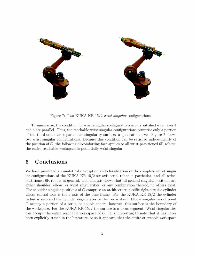
Figure 7: Two KUKA KR-15/2 wrist singular configurations.
To summarise, the condition for wrist singular configurations is only satisfied when axes 4and 6 are parallel. Thus, the reachable wrist singular configurations comprise only a portionof the third-order wrist parameter singularity surface: a quadratic curve. Figure 7 showstwo wrist singular configurations. Because this condition can be satisfied independently ofthe position of C, the following discomforting fact applies to all wrist-partitioned 6R robots:the entire reachable workspace is potentially wrist singular.
5 Conclusions
We have presented an analytical description and classification of the complete set of singu-lar configurations of the KUKA KR-15/2 six-axis serial robot in particular, and all wrist-partitioned 6R robots in general. The analysis shows that all general singular positions areeither shoulder, elbow, or wrist singularities, or any combination thereof, no others exist.The shoulder singular positions of C comprise an architecture specific right circular cylinderwhose central axis is the z-axis of the base frame. For the KUKA KR-15/2 the cylinderradius is zero and the cylinder degenerates to the z-axis itself. Elbow singularities of pointC occupy a portion of a torus, or double sphere, however, this surface is the boundary ofthe workspace. For the KUKA KR-15/2 the surface is a torus segment. Wrist singularitiescan occupy the entire reachable workspace of C. It is interesting to note that it has neverbeen explicitly stated in the literature, or so it appears, that the entire orientable workspace
13

is potentially singular, even in papers dealing specifically with orientation singularities, suchas [10].
While these results are not entirely new, the geometric analysis of the conditions thatcause the Jacobian to become rank deficient are. When the robot suddenly jerks to a haltbecause the controller has anticipated motion through a singularity, the operator is oftenleft mystified, despite the clarity of the error message that a singular configuration has beenreached. We believe that presenting the conditions in this way allows the users of wrist-partitioned industrial robots to better understand their singular configurations.
6 Acknowledgements
The images in Figures 1, 3, and 5 appear courtesy of Prof. Jorge Angeles. They are fromhis book Fundamentals of Robotic Mechanical Systems, and are reproduced herein withpermission of Springer-Verlag New York, Inc..
References
[1] R.P. Paul. Robot Manipulators: Mathematics, Programming and Control. MIT Press, Cam-bridge, MA., U.S.A., 1982.
[2] J. Angeles. Fundamentals of Robotic Mechanical Systems: Theory, Methods, and Algorithms.Springer-Verlag, New York, N.Y., U.S.A., 1997.
[3] L. Sciavicco and B. Sciliano. Modeling and Control of Robot Manipulators. Springer-Verlag,New York, N.Y., U.S.A., 2000.
[4] M.M. Stanisic and J.W. Engelberth. “A Cartesian Description of Arm-Subassembly Singular-ities in Terms of Singular Surfaces”. ASME Mechanisms Conference, Orlando, Fla., U.S.A.,pages 325–332, 1988.
[5] J.W. Burdick. “A Classification of 3R Regional Manipulator Singularities and Geometries”.Mechanism and Machine Theory, vol. 30, no. 1: pages 71–89, 1995.
[6] K. Tchon and R. Muszynski. “Singularities of Nonredundant Robot Kinematics”. InternationalJournal of Robotics Research, vol. 16, no. 1: pages 60–76, 1997.
[7] J.E. Lloyd and V. Hayward. “Removing the Singularities of Serial Manipulators by Trans-forming the Workspace”. In International Conference on Robotics and Automation, pages2935–2940, Leuven, Belgium, May 1998.
[8] A. Karger. “Classification of Serial Robot-Manipulators with Nonremovable Singularities”.ASME, Journal of Mechanical Design, vol. 118, no. 2: pages 202–208, 1996.
[9] M. Husty and A. Karger. “Architecture Singular Parallel Manipulators and Their Self-Motions”. Advances in Robotic Kinematics, eds. Lenarcic, J., Stanisic, Kluwer AcademicPublishers, Dordrecht, The Netherlands, pages 355–364, 2000.
14

[10] K. Tchon. “Singularities of the Euler Wrist”. Mechanism and Machine Theory, vol. 35: pages505–515, 2000.
[11] K.H. Hunt. Kinematic Geometry of Mechanisms. Clarendon Press, Oxford, England, 1978.
[12] K.H. Hunt. “Special Configurations of Robot Arms via Screw Theory”. Robotica, vol. 4: pages171–179, 1986.
[13] G.L. Long. “Use of the Cylindroid for the Singularity Analysis of Rank 3 Robotic Manipula-tors”. Mechanism and Machine Theory, vol. 32, no. 3: pages 391–404, 1997.
[14] A. Karger. “Singularity Analysis of Serial Robot-Manipulators”. ASME, Journal of MechanicalDesign, vol. 118, no. 4: pages 520–525, 1996.
[15] S.L. Wang and K.J. Waldron. “A Study of the Singular Configurations of Serial Manipulators”.ASME, J. of Mechanisms, Transmissions, & Automation in Design, vol. 109: pages 14–20,1987.
[16] M.S. Hsu and D. Kohli. “Boundary Surfaces and Accessibility Regions for Regional Structuresof Manipulators”. Mechanism and Machine Theory, vol. 22, no. 3: pages 277–289, 1987.
[17] H. Lipkin and E. Pohl. “Enumeration of Singular Configurations for Robotic Manipulators”.ASME Journal of Mechanical Design, vol. 113: pages 272–279, 1991.
[18] K.L. Doty. Jacobians and Singularities. Technical Report MIL050992kld, Machine IntelligenceLaboratory, University of Florida, May 9, 1992.
[19] F.T. Cheng, T.L. Hour, Y.Y. Sun, and T.H. Chen. “Study and Resolution of Singularities fora 6-DOF PUMA Manipulator”. IEEE Trans. on Sys., Man, and Cyb., Part B: Cybernetics,vol. 27, no. 2: pages 332–343, 1997.
[20] KUKA Documentation CD. KUKA Roboter GmbH, 1998.
[21] Kawasaki JS10-A09 Robot Operation Manual. Kawasaki Heavy Industries, Ltd., Robot Divi-sion, July 1990.
[22] Mitsubishi RV-M2 Industrial Micro-Robot System Instruction Manual. Mitsubishi ElectricCorporation.
[23] J. Denavit and R.S. Hartenberg. “A Kinematic Notation for Lower-Pair Mechanisms Basedon Matrices”. J. of Applied Mechanics, pages 215–221, 1955.
[24] F. Klein. Elementary Mathematics from an Advanced Standpoint: Geometry. Dover Publica-tions, Inc., New York, N.Y., U.S.A., 1939.
[25] B. Jacob. Linear Algebra. W.H. Freeman & Co., New York, N.Y., U.S.A., 1989.
15