Single Story Enclosed Shopping Mall Smoke Control with ...
57
1 Single Story Enclosed Shopping Mall Smoke Control with FSCS Override - Metasys® System Extended Architecture Application Note Document Introduction . . . . . . . . . . . . . . . . . . . . . . . . . . . . . . . . . . . . . . . . . . . . . . . . . 3 Related Documentation . . . . . . . . . . . . . . . . . . . . . . . . . . . . . . . . . . . . . . . . . . . . . . . . . 3 Application Overview . . . . . . . . . . . . . . . . . . . . . . . . . . . . . . . . . . . . . . . . . . . . . . . . . . 4 Building Overview . . . . . . . . . . . . . . . . . . . . . . . . . . . . . . . . . . . . . . . . . . . . . . . . . . . . . . . . 4 Smoke Control Priority Levels . . . . . . . . . . . . . . . . . . . . . . . . . . . . . . . . . . . . . . . . . . . . . . 6 Automatic Smoke Control . . . . . . . . . . . . . . . . . . . . . . . . . . . . . . . . . . . . . . . . . . . . . . . . . . 7 Manual Smoke Control . . . . . . . . . . . . . . . . . . . . . . . . . . . . . . . . . . . . . . . . . . . . . . . . . . . . 7 Auto Command Retry Logic . . . . . . . . . . . . . . . . . . . . . . . . . . . . . . . . . . . . . . . . . . . . . . . . 8 FSCS . . . . . . . . . . . . . . . . . . . . . . . . . . . . . . . . . . . . . . . . . . . . . . . . . . . . . . . . . . . . . . . . . . . 8 Assigning the Fire Object Category to Smoke Control Objects . . . . . . . . . . . . . . . . . . 10 Security Administration System. . . . . . . . . . . . . . . . . . . . . . . . . . . . . . . . . . . . . . . . . . . . 10 Roles and User Accounts Overview . . . . . . . . . . . . . . . . . . . . . . . . . . . . . . . . . . . . . . . . . . 11 UUKL Smoke Control Security Administration Details . . . . . . . . . . . . . . . . . . . . . . . . . . . . . 11 Security Administration Detailed Procedures . . . . . . . . . . . . . . . . . . . . . . . . . . . . . . . . . . . . 13 Creating a New Role . . . . . . . . . . . . . . . . . . . . . . . . . . . . . . . . . . . . . . . . . . . . . . . . . . . . . . . . . . 13 Creating a New User Account . . . . . . . . . . . . . . . . . . . . . . . . . . . . . . . . . . . . . . . . . . . . . . . . . . . 13 Configuring User Profiles . . . . . . . . . . . . . . . . . . . . . . . . . . . . . . . . . . . . . . . . . . . . . . . . . . . . . . . 13 Configuring Role Properties . . . . . . . . . . . . . . . . . . . . . . . . . . . . . . . . . . . . . . . . . . . . . . . . . . . . 13 Assigning System Access Permissions . . . . . . . . . . . . . . . . . . . . . . . . . . . . . . . . . . . . . . . . . . . . 13 Design Considerations . . . . . . . . . . . . . . . . . . . . . . . . . . . . . . . . . . . . . . . . . . . . . . . . 14 DX Design Considerations . . . . . . . . . . . . . . . . . . . . . . . . . . . . . . . . . . . . . . . . . . . . . . . . 14 Smoke Control NAE Design Considerations. . . . . . . . . . . . . . . . . . . . . . . . . . . . . . . . . . 15 DX-9100 Mall Smoke Control Application . . . . . . . . . . . . . . . . . . . . . . . . . . . . . . . . . 17 Application File Location . . . . . . . . . . . . . . . . . . . . . . . . . . . . . . . . . . . . . . . . . . . . . . . . . 17 GX Control Logic . . . . . . . . . . . . . . . . . . . . . . . . . . . . . . . . . . . . . . . . . . . . . . . . . . . . . . . 17 Point List . . . . . . . . . . . . . . . . . . . . . . . . . . . . . . . . . . . . . . . . . . . . . . . . . . . . . . . . . . . . . . . 18 GX Configuration Parameters. . . . . . . . . . . . . . . . . . . . . . . . . . . . . . . . . . . . . . . . . . . . . . 21 Single Story Enclosed Shopping Mall Smoke Control with FSCS Override - Metasys® System Extended Architecture Application Note Code No. LIT-1201736 Release 1.2 Issued January 10, 2005
Transcript of Single Story Enclosed Shopping Mall Smoke Control with ...

1Single Story Enclosed Shopping Mall Smoke Control with FSCS Override -Metasys® System Extended Architecture Application Note
Document Introduction . . . . . . . . . . . . . . . . . . . . . . . . . . . . . . . . . . . . . . . . . . . . . . . . . 3Related Documentation. . . . . . . . . . . . . . . . . . . . . . . . . . . . . . . . . . . . . . . . . . . . . . . . . 3Application Overview . . . . . . . . . . . . . . . . . . . . . . . . . . . . . . . . . . . . . . . . . . . . . . . . . . 4
Building Overview . . . . . . . . . . . . . . . . . . . . . . . . . . . . . . . . . . . . . . . . . . . . . . . . . . . . . . . . 4
Smoke Control Priority Levels . . . . . . . . . . . . . . . . . . . . . . . . . . . . . . . . . . . . . . . . . . . . . . 6
Automatic Smoke Control . . . . . . . . . . . . . . . . . . . . . . . . . . . . . . . . . . . . . . . . . . . . . . . . . . 7
Manual Smoke Control . . . . . . . . . . . . . . . . . . . . . . . . . . . . . . . . . . . . . . . . . . . . . . . . . . . . 7
Auto Command Retry Logic . . . . . . . . . . . . . . . . . . . . . . . . . . . . . . . . . . . . . . . . . . . . . . . . 8
FSCS . . . . . . . . . . . . . . . . . . . . . . . . . . . . . . . . . . . . . . . . . . . . . . . . . . . . . . . . . . . . . . . . . . . 8
Assigning the Fire Object Category to Smoke Control Objects . . . . . . . . . . . . . . . . . . 10
Security Administration System. . . . . . . . . . . . . . . . . . . . . . . . . . . . . . . . . . . . . . . . . . . . 10
Roles and User Accounts Overview . . . . . . . . . . . . . . . . . . . . . . . . . . . . . . . . . . . . . . . . . . 11
UUKL Smoke Control Security Administration Details . . . . . . . . . . . . . . . . . . . . . . . . . . . . . 11
Security Administration Detailed Procedures. . . . . . . . . . . . . . . . . . . . . . . . . . . . . . . . . . . . 13
Creating a New Role . . . . . . . . . . . . . . . . . . . . . . . . . . . . . . . . . . . . . . . . . . . . . . . . . . . . . . . . . . 13
Creating a New User Account . . . . . . . . . . . . . . . . . . . . . . . . . . . . . . . . . . . . . . . . . . . . . . . . . . . 13
Configuring User Profiles . . . . . . . . . . . . . . . . . . . . . . . . . . . . . . . . . . . . . . . . . . . . . . . . . . . . . . . 13
Configuring Role Properties . . . . . . . . . . . . . . . . . . . . . . . . . . . . . . . . . . . . . . . . . . . . . . . . . . . . 13
Assigning System Access Permissions . . . . . . . . . . . . . . . . . . . . . . . . . . . . . . . . . . . . . . . . . . . . 13
Design Considerations . . . . . . . . . . . . . . . . . . . . . . . . . . . . . . . . . . . . . . . . . . . . . . . . 14DX Design Considerations . . . . . . . . . . . . . . . . . . . . . . . . . . . . . . . . . . . . . . . . . . . . . . . . 14
Smoke Control NAE Design Considerations. . . . . . . . . . . . . . . . . . . . . . . . . . . . . . . . . . 15
DX-9100 Mall Smoke Control Application . . . . . . . . . . . . . . . . . . . . . . . . . . . . . . . . . 17Application File Location . . . . . . . . . . . . . . . . . . . . . . . . . . . . . . . . . . . . . . . . . . . . . . . . . 17
GX Control Logic . . . . . . . . . . . . . . . . . . . . . . . . . . . . . . . . . . . . . . . . . . . . . . . . . . . . . . . 17
Point List. . . . . . . . . . . . . . . . . . . . . . . . . . . . . . . . . . . . . . . . . . . . . . . . . . . . . . . . . . . . . . . 18
GX Configuration Parameters. . . . . . . . . . . . . . . . . . . . . . . . . . . . . . . . . . . . . . . . . . . . . . 21
Single Story Enclosed Shopping Mall Smoke Control with FSCS Override - Metasys® System Extended ArchitectureApplication Note
Code No. LIT-1201736Release 1.2
Issued January 10, 2005

Single Story Enclosed Shopping Mall Smoke Control with FSCS Override - Metasys® System Extended Architecture Application Note
2
Smoke Control NAE Application . . . . . . . . . . . . . . . . . . . . . . . . . . . . . . . . . . . . . . . . 28Application File Location . . . . . . . . . . . . . . . . . . . . . . . . . . . . . . . . . . . . . . . . . . . . . . . . . 28
Metasys System Extended Architecture Objects . . . . . . . . . . . . . . . . . . . . . . . . . . . . . . 28
Mall Control . . . . . . . . . . . . . . . . . . . . . . . . . . . . . . . . . . . . . . . . . . . . . . . . . . . . . . . . . 29Mall Logic . . . . . . . . . . . . . . . . . . . . . . . . . . . . . . . . . . . . . . . . . . . . . . . . . . . . . . . . . . . . . . 29
All Store Logic . . . . . . . . . . . . . . . . . . . . . . . . . . . . . . . . . . . . . . . . . . . . . . . . . . . . . . . . . . 32
Store 1 Logic . . . . . . . . . . . . . . . . . . . . . . . . . . . . . . . . . . . . . . . . . . . . . . . . . . . . . . . . . . . . 33
Store 2 Logic . . . . . . . . . . . . . . . . . . . . . . . . . . . . . . . . . . . . . . . . . . . . . . . . . . . . . . . . . . . . 33
Store 3 Logic . . . . . . . . . . . . . . . . . . . . . . . . . . . . . . . . . . . . . . . . . . . . . . . . . . . . . . . . . . . . 34
Store 4 Logic . . . . . . . . . . . . . . . . . . . . . . . . . . . . . . . . . . . . . . . . . . . . . . . . . . . . . . . . . . . . 34
Store 5 Logic . . . . . . . . . . . . . . . . . . . . . . . . . . . . . . . . . . . . . . . . . . . . . . . . . . . . . . . . . . . . 35
Store 6 Logic . . . . . . . . . . . . . . . . . . . . . . . . . . . . . . . . . . . . . . . . . . . . . . . . . . . . . . . . . . . . 35
Mall Logic. . . . . . . . . . . . . . . . . . . . . . . . . . . . . . . . . . . . . . . . . . . . . . . . . . . . . . . . . . . . . . . 36
Alarm Lockout . . . . . . . . . . . . . . . . . . . . . . . . . . . . . . . . . . . . . . . . . . . . . . . . . . . . . . . . . . . 36
Lockout Logic. . . . . . . . . . . . . . . . . . . . . . . . . . . . . . . . . . . . . . . . . . . . . . . . . . . . . . . . . . . . 37
FSCS Control . . . . . . . . . . . . . . . . . . . . . . . . . . . . . . . . . . . . . . . . . . . . . . . . . . . . . . . . . . . 38
FSCS Store 2 Smoke Interlock Definition . . . . . . . . . . . . . . . . . . . . . . . . . . . . . . . . . . . . . . 38
3rd Party Zone Interlock Definition. . . . . . . . . . . . . . . . . . . . . . . . . . . . . . . . . . . . . . . . . . . . 39
FSCS Zone Switch Logic . . . . . . . . . . . . . . . . . . . . . . . . . . . . . . . . . . . . . . . . . . . . . . . . . . . 39
FSCS Store 2 Exhaust Fan 1 Logic . . . . . . . . . . . . . . . . . . . . . . . . . . . . . . . . . . . . . . . . . . . 44
FSCS Store 2 Supply Fan 1 Logic . . . . . . . . . . . . . . . . . . . . . . . . . . . . . . . . . . . . . . . . . . 49
FSCS Zone Smoke LED Logic . . . . . . . . . . . . . . . . . . . . . . . . . . . . . . . . . . . . . . . . . . . . . 54
Zone Smoke LED - IFC Zone Detector Trouble Interlock Definition . . . . . . . . . . . . . . . . . . 55
Zone Smoke LED - IFC Zone Trouble Interlock Definition. . . . . . . . . . . . . . . . . . . . . . . . . . 55
Zone Smoke LED - 3rd Party Zone Trouble Interlock Definition . . . . . . . . . . . . . . . . . . . . . 56
Fire Fighter Control Logic. . . . . . . . . . . . . . . . . . . . . . . . . . . . . . . . . . . . . . . . . . . . . . . . . 57

Single Story Enclosed Shopping Mall Smoke Control with FSCS Override - Metasys® System Extended Architecture Application Note
3
Single Story Enclosed Shopping Mall Smoke Control with FSCS Override - Metasys® System Extended ArchitectureApplication Note
Document IntroductionSmoke control applications issue commands to controlled devices that pressurize or depressurize an area of a building to minimize the spread of smoke. This document describes smoke control of a single story enclosed shopping mall in the Metasys system extended architecture.
The smoke control strategy is achieved with the DX-9100 (DX) application and the smoke control Network Automation Engine (NAE) application described in this document, with manual override of the smoke control logic provided by the Fire Fighter’s Smoke Control Station (FSCS).
Note: These application notes only present an example of one smoke control strategy. Since every building is unique, the details of applying the strategy vary. These application notes can help you develop an appropriate application for your project.
Related DocumentationTable 1 lists related smoke control documentation.Table 1: Related DocumentationFor Information On Refer To LIT No./Part No.General smoke control information Metasys System Extended Architecture
Smoke Control System Technical BulletinLIT-1201684
Logic programming for the DX-9100 controller
GX-9100 Software Configuration Tool Technical Bulletin
LIT-6364060
Multi-story building smoke control Multi-Story Building Smoke Control with FSCS Override - Metasys System Extended Architecture Application Note
LIT-1201737
Warehouse smoke control Warehouse Smoke Control with FSCS Override - Metasys System Extended Architecture Application Note
LIT-1201738
Weekly testing of dedicated stairwell pressurization fans
Weekly Testing of Dedicated Stairwell Pressurization Fans - Metasys System Extended Architecture Application Note
LIT-1201739
Weekly testing of dedicated smoke control dampers
Weekly Testing of Dedicated Smoke Control Dampers - Metasys System Extended Architecture Application Note
LIT-1201743
Specific wiring requirements Metasys System Extended Architecture Smoke Control Wiring Technical Bulletin
LIT-1201753
UL® 864 UUKL requirements MSEA Smoke Control UL 864 UUKL Compliance Checklist
LIT-1201754
Single Story Enclosed Shopping Mall Smoke Control with FSCS Override - Metasys® System Extended Architecture Application Note
4
Application OverviewThe DX application and the smoke control NAE application both provide smoke control for a single story mall with a rooftop unit. The DX controllers provide field connections, and the DX application provides basic HVAC and automatic smoke control for the rooftop unit. The smoke control NAE provides a connection to the FSCS, and the smoke control NAE application provides automatic smoke control and fire fighter manual override for the smoke control system.
Note: These application notes only present an example of one smoke control strategy. Since every building is unique, the details of applying the strategy vary. These application notes can help you develop an appropriate application for your project.
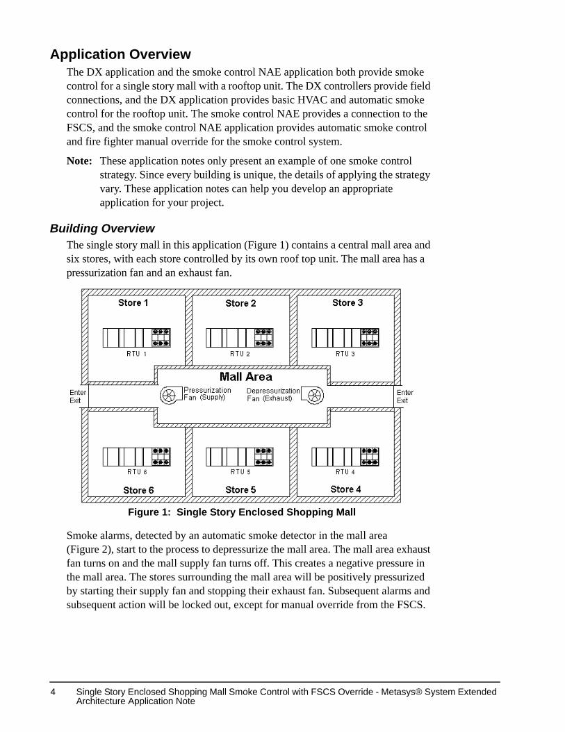
Building OverviewThe single story mall in this application (Figure 1) contains a central mall area and six stores, with each store controlled by its own roof top unit. The mall area has a pressurization fan and an exhaust fan.
Smoke alarms, detected by an automatic smoke detector in the mall area (Figure 2), start to the process to depressurize the mall area. The mall area exhaust fan turns on and the mall supply fan turns off. This creates a negative pressure in the mall area. The stores surrounding the mall area will be positively pressurized by starting their supply fan and stopping their exhaust fan. Subsequent alarms and subsequent action will be locked out, except for manual override from the FSCS.
Figure 1: Single Story Enclosed Shopping Mall

Single Story Enclosed Shopping Mall Smoke Control with FSCS Override - Metasys® System Extended Architecture Application Note
5
The system only returns to the pre-smoke control configuration when all automatic alarm/smoke control initiating devices return to the normal condition, and the manual override switches on the FSCS return to the Auto position.
Figure 2: Smoke Detected in the Mall Area
Single Story Enclosed Shopping Mall Smoke Control with FSCS Override - Metasys® System Extended Architecture Application Note
6
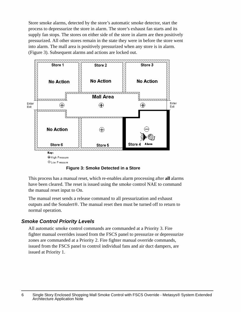
Store smoke alarms, detected by the store’s automatic smoke detector, start the process to depressurize the store in alarm. The store’s exhaust fan starts and its supply fan stops. The stores on either side of the store in alarm are then positively pressurized. All other stores remain in the state they were in before the store went into alarm. The mall area is positively pressurized when any store is in alarm. (Figure 3). Subsequent alarms and actions are locked out.
This process has a manual reset, which re-enables alarm processing after all alarms have been cleared. The reset is issued using the smoke control NAE to command the manual reset input to On.
The manual reset sends a release command to all pressurization and exhaust outputs and the Sonalert®. The manual reset then must be turned off to return to normal operation.
Smoke Control Priority LevelsAll automatic smoke control commands are commanded at a Priority 3. Fire fighter manual overrides issued from the FSCS panel to pressurize or depressurize zones are commanded at a Priority 2. Fire fighter manual override commands, issued from the FSCS panel to control individual fans and air duct dampers, are issued at Priority 1.
Figure 3: Smoke Detected in a Store

Single Story Enclosed Shopping Mall Smoke Control with FSCS Override - Metasys® System Extended Architecture Application Note
7
Automatic Smoke ControlAutomatic Smoke Control provides the logic for UUKL first incident rule by locking out subsequent alarms from automatic smoke control. All Store logic depressurizes the store that goes into smoke alarm and pressurizes all adjacent stores. Pressurize and depressurize commands in automatic smoke control are commanded at a Priority 3. Priority 3 commands are released when the smoke alarm is reset.
If a store or the mall area is under smoke control, the FSCS panel controls the Light-Emitting Diodes (LEDs) next to each FSCS switch to indicate the current status of the fans, dampers, and zone. Status LEDs for a fan show whether the fan is either On, Off, or in Trouble. Status LEDs for a damper indicate whether the damper is either Open, Closed, or in Trouble. Status LEDs for a zone (store/mall area) indicate whether the zone is either in Pressurize mode, Depressurize mode or Purge mode. The Auto LED for each fan, damper, and zone switch remains on while the point is in automatic smoke control.
The logic to check the status of fans and dampers for trouble is initiated when a store or the mall area goes into smoke control. If a fan does not reach its set point within 60 seconds, its Trouble LED is turned on. If a damper does not reach its set point within 75 seconds, its Trouble LED is turned on. After a commanded point goes into Trouble, the Auto Command Retry logic repeats the command that failed every 60 seconds. For more detailed information, see the Design Considerations section in this manual.
Manual Smoke ControlManual Smoke Control logic is initiated when a fire fighter turns the FSCS Panel Enable key from the Auto position to the Fire Fighter Control position and initiates a manual override of a fan, damper, or zone point from the Auto setting on the FSCS panel. This turns off the Panel Enable switch Auto LED and turns on the Panel Enable switch Fire Fighter Control LED.
There are two levels of manual smoke control. A fire fighter can put a store in manual smoke control by turning the zone knob to Pressurize, Depressurize, or Purge. The zone smoke control commands are issued at Priority 2. Priority 2 commands are released when the fire fighter turns the zone knob back to Auto or turns the Panel Enable key back to Auto.
A fire fighter can put a point in manual smoke control by flipping a fan toggle switch to On or Off or a damper toggle switch to Open or Close. Individual points are commanded at Priority 1. Priority 1 commands are released when the fire fighter turn flips the toggle switch to Auto or turns the Panel Enable key back to Auto.

Single Story Enclosed Shopping Mall Smoke Control with FSCS Override - Metasys® System Extended Architecture Application Note
8
Any point under manual smoke control activates the trouble checking logic. If a fan does not reach its set point within 60 seconds, its Trouble LED is turned on. If a damper does not reach its set point within 75 seconds, its Trouble LED is turned on. After a commanded point goes into Trouble, the Auto Command Retry logic repeats the command that failed every 60 seconds. For more detailed information, see the Design Considerations section in this manual.
Auto Command Retry LogicThe Auto Command Retry logic is used for fans, dampers, and VMAs. It does a comparison check between the commanded state and the actual device state, to verify that the command was successful. In the event a command to a fan, damper, or VMA fails, possibly because the MCO for the commanded device is on a remote smoke control NAE panel. The additional time required to communicate with the remote smoke control NAE might exceed the command response limit. Therefore, the command is resent every 60 seconds until the command is successful.
The Auto Command Retry logic is used when either a device MCO does not match command, a fan, damper, or VMA status does not match its commanded value, or a fan, damper, or VMA trouble input is active.
FSCSThe FSCS is responsible for all Sonalert logic. When an LED value is set to 3 or 4, the Sonalert sounds. Press the Silence button on the FSCS panel to silence the Sonalert and change the LED to a slow blink. The LED will remain on slow blink until it is commanded off. The panel will start a timer and resound the sonalert within 24 hours if the LED is not turned off. The FSCS panel switches and LEDs for the Mall Common Area are shown in Figure 4. Each store in the mall has similar panel controls.The controls shown under the Mall Common Area zone are master controls for the entire FSCS mall control panel.
Figure 4: FSCS Panel - Mall Common Area

Single Story Enclosed Shopping Mall Smoke Control with FSCS Override - Metasys® System Extended Architecture Application Note
9
The Sonalert sounds if the FSCS Panel Enable key is turned from the Firefighter Control position to the Auto position and all zone knobs and point toggle switches are not set to Auto. The FSCS still goes into Auto mode, but the Sonalert reminds the firefighter to set the manual smoke control switches to the Auto position.
The General Trouble LED will be turned on to a fast blink if the panel looses N2 communications.The LEDs on the FSCS panel can be set to the following values (Table 2).Table 2: FSCS LED Blink Condition FSCS LED Value LED Blink Condition0 LED is off1 LED is on continuously2 LED slow blink3 LED fast blink and sonalert turned on

Single Story Enclosed Shopping Mall Smoke Control with FSCS Override - Metasys® System Extended Architecture Application Note
10
Assigning the Fire Object Category to Smoke Control ObjectsYou must assign every object used specifically for smoke control as a Fire object. This limits the control of smoke control devices and points to authorized Fire operators.Use the pull down menu to assign the Fire object category (Figure 5).
Security Administration SystemThe Security Administration system authenticates and authorizes users of Metasys® system extended architecture applications. The Security Administrator is a browser-based interface that manages all accounts.
Use the Security Administrator System to authenticate and authorize users on the Metasys system extended architecture. The Security Administrator creates User Accounts and Roles, and assigns access permissions to each user of the Metasys system extended architecture.
!WARNING: Risk of serious injury or death if a smoke control object is not assigned as a Fire object! In the event of a fire or smoke control event, devices or points used for smoke control that are not assigned as Fire objects allow those devices and points to be controlled by non-fire authorized operators. It is imperative that every smoke control device or point be assigned as a Fire object.
Figure 5: Assigning the Fire Object to Smoke Control Objects

Single Story Enclosed Shopping Mall Smoke Control with FSCS Override - Metasys® System Extended Architecture Application Note
11
Roles and User Accounts OverviewSecurity is based on User Accounts and Roles. Roles are groups of users with a specific function within the Metasys system. To access the system, an individual provides a user account and the correct password. Use letters, numbers, or symbols to create user account passwords.
Use the Login button from the logon prompt to send the user’s credentials. A unique Session generates when the user’s credentials match the logon requirements.
UUKL Smoke Control Security Administration DetailsUUKL smoke control requires that only operators designated as fire operators be able to control the smoke control system. This required the creation of four new roles:
1. Administrator - This is the highest level of control and allows site control of all HVAC and Fire features.Fire Administrator - This role is a fire manager level setting. It allows for full system control, including system modification or configuration.
2. Fire Administrator - This role is a fire manager level setting. It allows for full system control, including system modification or configuration.
Figure 6: Fire Administrator Access Permissions

Single Story Enclosed Shopping Mall Smoke Control with FSCS Override - Metasys® System Extended Architecture Application Note
12
3. Fire User - This role is for most fire field technicians and allows system control and alarm acknowledgement, but not system modification or configuration.
4. Fire Limited - This is the lowest of the permissions and only allows the operator to view fire/smoke control devices and alarms.
Figure 7: Fire User Access Permissions
Figure 8: Fire Limited Access Permissions

Single Story Enclosed Shopping Mall Smoke Control with FSCS Override - Metasys® System Extended Architecture Application Note
13
Security Administration Detailed Procedures
Creating a New RoleTo create a new role:
1. From the Security Administration menu bar, select Insert > New Role. The New Role dialog box appears.
2. Fill in the information.
3. Click OK. The New Role appears in the tree.
Creating a New User AccountTo create a new user account:
1. From the Security Administration menu bar, select Insert > New User. The User Properties tab appears.
2. Fill in the information.
3. Click OK. The New User appears in the tree.
Configuring User ProfilesTo configure a user profile:
1. Select the user whom you wish to configure.
2. From the menu bar, select Edit > Properties. The User Properties tab appears.
3. Modify the desired user information.
4. Click OK.
Configuring Role PropertiesTo configure role properties:
1. Select the user whom you wish to configure.
2. From the menu bar, select Edit > Properties. The User Properties tab appears.
3. Select the Roles tab, then select an Available Role.
4. Click Add. The selected role appears in the Assigned Role list box.
5. Click OK.
Assigning System Access PermissionsTo assign system access permissions:
1. Select the user whom you wish to assign system access permissions.
2. From the main menu, select Edit > System Access Permissions. The System Access Permission dialog box appears.
3. Select an available privilege.
4. Click Add, then click OK to assign the user’s System Access Permissions.

Single Story Enclosed Shopping Mall Smoke Control with FSCS Override - Metasys® System Extended Architecture Application Note
14
Design ConsiderationsThis DX-9100 and Smoke Control NAE application, as it exists in the Metasys System Extended Architecture Smoke Control Library, complies with the UL 864 UUKL Smoke Listing. However, you are responsible for ensuring that the application complies with state and local regulations, and is approved by the Authority Having Jurisdiction (AHJ). You are also responsible for configuring all of the smoke control components, as well as the programming of those components, in order to comply with the UL 864 UUKL Smoke Listing as documented herein.
DX Design ConsiderationsFor information on the definition and the initial configuration of this DX-9100 smoke control application, use the GX-9100 Software Configuration Tool (GX Tool) to examine this smoke control application.
You can find instructions and guidelines for using the GX Tool in the GX-9100 Software Configuration Tool Technical Bulletin (LIT-6364060).
• You may define system and object names for all objects.
• You must define the hardware location for each object.
• The process runs once per second, since this is the DX-9100 scan rate.
An alarm will occur if the command does not equal the condition for any controlled device output. Each Binary Output (BO) for pressurization and exhaust outputs must be configured to have its own feedback (proof sensor) input. The system will indicate when the command does not equal the condition. The alarm must be used in other applications, such as a graphical presentation of feedback information, use the FSCS.
• This DX-9100 automatic smoke control application does not provide a manual override. Override is available from the operator at the smoke control NAE or the FSCS.
• For multi-level structures, use the same, predefined program. You may want to positively pressurize the stores above and below the area of incidence, subject to the approval of the AHJ.
• Depending on the application and the specifics of the building, the same logic may be used in atriums, subject to the approval of the AHJ.
• Using multiple DX-9100s, this application can be expanded to work for a mall with six or more stores. For further details, please contact the Field Support Center in Milwaukee.

Single Story Enclosed Shopping Mall Smoke Control with FSCS Override - Metasys® System Extended Architecture Application Note
15
For UL compliance:
• If DX Digital Inputs (DIs) are used for smoke control, then DI8 must be jumpered and mapped to the smoke control NAE as a normal state of On. If DI8 is off, a critical alarm must be issued at the FSCS to indicate a binary input fuse failure that must be fixed immediately, because the DI is no longer accurate.
• If DX Analog Outputs (AOs) are used for smoke control, then Analog Output 14 (AO14, voltage) must be wired to Analog Input 8 (AI8, voltage) and the AI must be mapped to the smoke control NAE with a low alarm limit of 20%. If the AI goes below 20%, it indicates the AO has failed because of a blown fuse, which drops the AO to 0V and the AI to 0% (low alarm). The DX is downloaded so that the AO is normally at 5V because its source point is an Analog Constant (ACO) with a default of 50.
• Response time for individual smoke control components to achieve their desired state of operational mode, exclusive of control system response, should not exceed the following time periods: 60 seconds for fan operation at the desired state plus 90 seconds to annunciate; 75 seconds for completion of damper travel plus 90 seconds to annunciate. In the case of fan start after damper close, these times are additive. If the damper must be closed before the fan starts, the total response time could be up to 135 seconds for operation, 75 seconds for damper to close plus 60 seconds for fan to start. Time to annunciate would be added to this time. (Control system response is the time from automatic detection of a smoke condition, to the issuing of an appropriate command to the equipment.)
• For specific wiring requirements, refer to Metasys Smoke Control Wiring Technical Bulletin (LIT-1201753).
• For specific wiring requirements refer to Metasys System Extended Architecture Smoke Control System Wiring Technical Bulletin (LIT-1201684).
Smoke Control NAE Design ConsiderationsKeep the following design considerations in mind when designing a single story enclosed shopping mall smoke control system with FSCS override:
• The smoke control NAE reports critical alarms based on the alarm condition, and the alarm can only be cleared by resetting from the Intelligent Fire Controller (IFC) panel or the Firefighter’s Smoke Control Station (FSCS).
• You must define the hardware location for each object
• You must name each object with a descriptive name that is unique in the system.

Single Story Enclosed Shopping Mall Smoke Control with FSCS Override - Metasys® System Extended Architecture Application Note
16
• A “Programming In Progress” BACnet Binary Value object (BV) point is required. You must set this point to true any time you are making changes to the Smoke Control system. This will turn on the Programming In Progress LED on the FSCS to let a fire fighter know that changes are being made and the system may not be fully functional. The point must be turned off when changes are complete.
• A master reset interlock is required. The interlock is true after the reset on the Intelligent Fire Controller (IFC) panel is pressed.
• Each store will need a Latched Alarm BV object. The lock alarm logic will set this point to true for the first alarm detected.
• Each store will need an Alarm Lockout Interlock. The interlock is true if any latched alarms for other stores is true or the master reset interlock is true. Do not include a store’s latched alarm in its own Alarm Lockout Interlock.
• A DX will need to provide the following BV points.
• zone pressurize command – Set to true to turn on supply fans
• zone depressurize command – Set to true to turn on exhaust fans
• BV Auto point – Normally set to true. Point is false when a fire fighter turns a fan On or Off, or sets a damper to Open or Close.
• BV command point for each fan
• BV feedback point for each fan
• BV command point for each damper
• BV open feedback point for each damper
• BV close feedback point for each damper
• BV point for the Analog Input (AI) Fuse
• BV point for the Binary Input (BI) Fuse
• Use the following priorities for commands to DX points.
• 3 – commands from automatic smoke control
• 2 – commands from manual smoke control for zone pressurize, depressurize, and purge.
• 1 – commands from manual smoke control for individual points.

Single Story Enclosed Shopping Mall Smoke Control with FSCS Override - Metasys® System Extended Architecture Application Note
17
DX-9100 Mall Smoke Control ApplicationApplication File Location
This Metasys system extended architecture smoke control application is located on the Metasys Branch Purchase Package (BPP) CD in the Metasys System Extended Architecture Standard Smoke Control Applications directory.
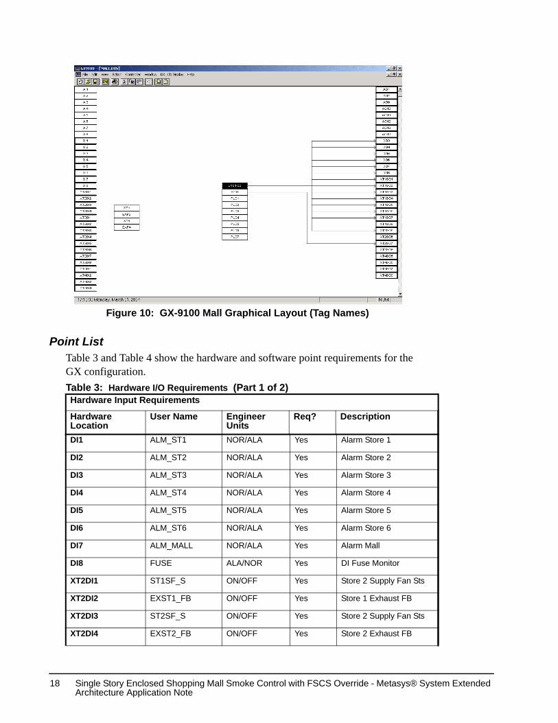
GX Control LogicThe GX Tool was used to create the logic for this DX single story enclosed shopping mall smoke control application. This DX smoke control application resides on each DX-9100 controller used for mall smoke control. The main GX screen shows the mall smoke control application as user names (Figure 9) or tag names (Figure 10) depending on the view selected.
Figure 9: GX-9100 Mall Graphical Layout (User Names)
Single Story Enclosed Shopping Mall Smoke Control with FSCS Override - Metasys® System Extended Architecture Application Note
18
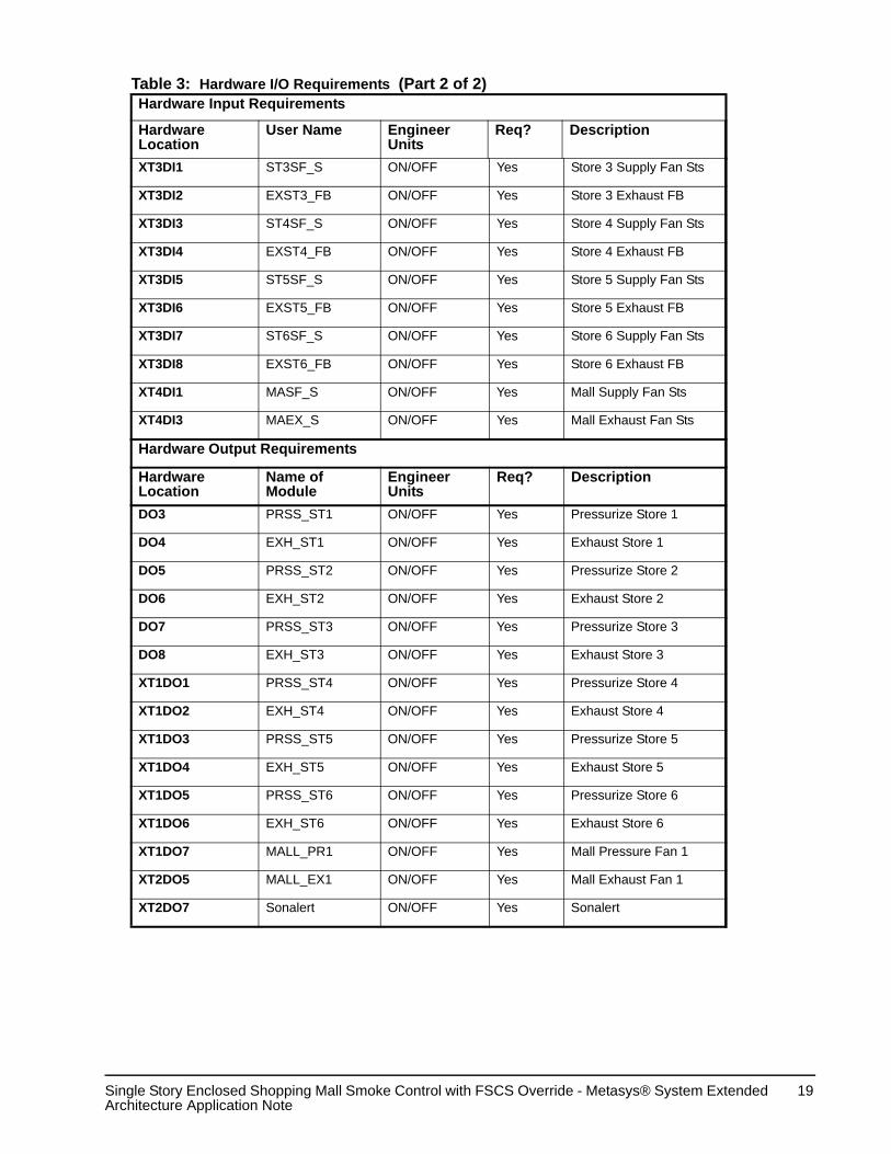
Point ListTable 3 and Table 4 show the hardware and software point requirements for the GX configuration.Table 3: Hardware I/O Requirements (Part 1 of 2)Hardware Input Requirements
Hardware Location
User Name Engineer Units
Req? Description
DI1 ALM_ST1 NOR/ALA Yes Alarm Store 1
DI2 ALM_ST2 NOR/ALA Yes Alarm Store 2
DI3 ALM_ST3 NOR/ALA Yes Alarm Store 3
DI4 ALM_ST4 NOR/ALA Yes Alarm Store 4
DI5 ALM_ST5 NOR/ALA Yes Alarm Store 5
DI6 ALM_ST6 NOR/ALA Yes Alarm Store 6
DI7 ALM_MALL NOR/ALA Yes Alarm Mall
DI8 FUSE ALA/NOR Yes DI Fuse Monitor
XT2DI1 ST1SF_S ON/OFF Yes Store 2 Supply Fan Sts
XT2DI2 EXST1_FB ON/OFF Yes Store 1 Exhaust FB
XT2DI3 ST2SF_S ON/OFF Yes Store 2 Supply Fan Sts
XT2DI4 EXST2_FB ON/OFF Yes Store 2 Exhaust FB
Figure 10: GX-9100 Mall Graphical Layout (Tag Names)
Single Story Enclosed Shopping Mall Smoke Control with FSCS Override - Metasys® System Extended Architecture Application Note
19
XT3DI1 ST3SF_S ON/OFF Yes Store 3 Supply Fan Sts
XT3DI2 EXST3_FB ON/OFF Yes Store 3 Exhaust FB
XT3DI3 ST4SF_S ON/OFF Yes Store 4 Supply Fan Sts
XT3DI4 EXST4_FB ON/OFF Yes Store 4 Exhaust FB
XT3DI5 ST5SF_S ON/OFF Yes Store 5 Supply Fan Sts
XT3DI6 EXST5_FB ON/OFF Yes Store 5 Exhaust FB
XT3DI7 ST6SF_S ON/OFF Yes Store 6 Supply Fan Sts
XT3DI8 EXST6_FB ON/OFF Yes Store 6 Exhaust FB
XT4DI1 MASF_S ON/OFF Yes Mall Supply Fan Sts
XT4DI3 MAEX_S ON/OFF Yes Mall Exhaust Fan Sts
Hardware Output Requirements
Hardware Location
Name of Module
Engineer Units
Req? Description
DO3 PRSS_ST1 ON/OFF Yes Pressurize Store 1
DO4 EXH_ST1 ON/OFF Yes Exhaust Store 1
DO5 PRSS_ST2 ON/OFF Yes Pressurize Store 2
DO6 EXH_ST2 ON/OFF Yes Exhaust Store 2
DO7 PRSS_ST3 ON/OFF Yes Pressurize Store 3
DO8 EXH_ST3 ON/OFF Yes Exhaust Store 3
XT1DO1 PRSS_ST4 ON/OFF Yes Pressurize Store 4
XT1DO2 EXH_ST4 ON/OFF Yes Exhaust Store 4
XT1DO3 PRSS_ST5 ON/OFF Yes Pressurize Store 5
XT1DO4 EXH_ST5 ON/OFF Yes Exhaust Store 5
XT1DO5 PRSS_ST6 ON/OFF Yes Pressurize Store 6
XT1DO6 EXH_ST6 ON/OFF Yes Exhaust Store 6
XT1DO7 MALL_PR1 ON/OFF Yes Mall Pressure Fan 1
XT2DO5 MALL_EX1 ON/OFF Yes Mall Exhaust Fan 1
XT2DO7 Sonalert ON/OFF Yes Sonalert
Table 3: Hardware I/O Requirements (Part 2 of 2)Hardware Input Requirements
Hardware Location
User Name Engineer Units
Req? Description

Single Story Enclosed Shopping Mall Smoke Control with FSCS Override - Metasys® System Extended Architecture Application Note
20
Table 4: Software I/O Requirements (Part 1 of 2)Hardware Location
User Name Req? Description
DCO1 STR1-OCC Yes Store 1 OccupiedDCO2 STR1-PRS Yes Store 1 PressurizeDCO3 STR1-EXH Yes Store 1 Exhaust DCO4 STR2-OCC Yes Store 2 OccupiedDCO5 STR2-PRS Yes Store 2 PressurizeDCO6 STR2-EXH Yes Store 2 ExhaustDCO7 STR3-OCC Yes Store 3 OccupiedDCO8 STR3-PRS Yes Store 3 PressurizeDCO9 STR3-EXH Yes Store 3 ExhaustDCO10 STR4-OCC Yes Store 4 OccupiedDCO11 STR4-PRS Yes Store 4 PressurizeDCO12 STR4-EXH Yes Store 4 ExhaustDCO13 STR5-OCC Yes Store 5 OccupiedDCO14 STR5-PRS Yes Store 5 PressurizeDCO15 STR5-EXH Yes Store 5 ExhaustDCO16 STR6-OCC Yes Store 6 OccupiedDCO17 STR6-PRS Yes Store 6 PressurizeDCO18 STR6-EXH Yes Store 6 ExhaustDCO19 MALL-OCC Yes Mall OccupiedDCO20 MALL-PRS Yes Mall PressurizeDCO21 MALL-EXH Yes Mall ExhaustDCO22 Sonalert Yes SonalertLRS1 SF1-AUTO Yes Store 1 Supply Fan AutoLRS2 STR1SF-C Yes Store 1 Supply Fan ControlLRS3 EF1-AUTO Yes Store 1 Exhaust Fan AutoLRS4 STR1EF-C Yes Store 1 Exhaust Fan ControlLRS5 SF2-AUTO Yes Store 2 Supply Fan AutoLRS6 STR2SF-C Yes Store 2 Supply Fan ControlLRS7 EF2-AUTO Yes Store 2 Exhaust Fan AutoLRS8 STR2EF-C Yes Store 2 Exhaust Fan ControlLRS9 SF3-AUTO Yes Store 3 Supply Fan AutoLRS10 STR3SF-C Yes Store 3 Supply Fan ControlLRS11 EF3-AUTO Yes Store 3 Exhaust Fan AutoLRS12 STR3EF-C Yes Store 3 Exhaust Fan ControlLRS13 SF4-AUTO Yes Store 4 Supply Fan AutoLRS14 STR4SF-C Yes Store 4 Supply Fan ControlLRS15 EF4-AUTO Yes Store 4 Exhaust Fan AutoLRS16 STR4EF-C Yes Store 4 Exhaust Fan ControlLRS17 SF5-AUTO Yes Store 5 Supply Fan AutoLRS18 STR5SF-C Yes Store 5 Supply Fan Control

Single Story Enclosed Shopping Mall Smoke Control with FSCS Override - Metasys® System Extended Architecture Application Note
21
GX Configuration ParametersThe Programmable Logic Controller (PLC) programs for each store and the mall area are shown in Figure 11 through Figure 17:
Note: If the fan feedback does not match the commanded state within 60 seconds, an alarm is generated.
The LRS outputs must be mapped to the NAE as critical alarms with a normal condition of Off (open).
Figure 11 shows the logic module ladder diagram for PLC1 (Store 1). The PLC 1 logic states:
• If Store 1 is in normal occupied mode (STR1-OCC), and not in alarm (STR1-EXH) and the FSCS Supply Fan switch is in either AUTO (SF1-AUTO) or in override (STR1SF-C), then turn the Store 1 RTU supply fan on.
LRS19 EF5-AUTO Yes Store 5 Exhaust Fan AutoLRS20 STR5EF-C Yes Store 5 Exhaust Fan ControlLRS21 SF6-AUTO Yes Store 6 Supply Fan AutoLRS22 STR6SF-C Yes Store 6 Supply Fan ControlLRS23 EF6-AUTO Yes Store 6 Exhaust Fan AutoLRS24 STR6EF-C Yes Store 6 Exhaust Fan ControlLRS25 MSF-AUTO Yes Mall Supply Fan AutoLRS26 MALLSF-C Yes Mall Supply Fan ControlLRS27 MEF-AUTO Yes Mall Exhaust Fan AutoLRS28 MALLEF-C Yes Mall Exhaust Fan Control
Table 4: Software I/O Requirements (Part 2 of 2)Hardware Location
User Name Req? Description
Figure 11: Logic Module Diagram - PLC1 (Store 1)

Single Story Enclosed Shopping Mall Smoke Control with FSCS Override - Metasys® System Extended Architecture Application Note
22
• If Store 1 is in normal occupied mode (STR1-OCC), and not in alarm (STR1-PRS) and the FSCS Exhaust Fan switch is in either AUTO (EF1-AUTO) or in override (STR1EF-C), then turn the Store 1 RTU exhaust fan on.
Figure 12 shows the logic module ladder diagram for PLC2 (Store 2). The PLC 2 logic states:
• If Store 2 is in normal occupied mode (STR2-OCC), and not in alarm (STR2-EXH) and the FSCS Supply Fan switch is in either AUTO (SF2-AUTO) or in override (STR2SF-C), then turn the Store 2 RTU supply fan on.
• If Store 2 is in normal occupied mode (STR2-OCC), and not in alarm (STR2-PRS) and the FSCS Exhaust Fan switch is in either AUTO (EF2-AUTO) or in override (STR2EF-C), then turn the Store 2 RTU exhaust fan on.
Figure 12: Logic Module Ladder - PLC2 (Store 2)

Single Story Enclosed Shopping Mall Smoke Control with FSCS Override - Metasys® System Extended Architecture Application Note
23
Figure 13 shows the logic module ladder diagram for PLC3 (Store 3). The PLC 3 logic states:
• If Store 3 is in normal occupied mode (STR3-OCC), and not in alarm (STR3-EXH) and the FSCS Supply Fan switch is in either AUTO (SF3-AUTO) or in override (STR3SF-C), then turn the Store 3 RTU supply fan on.
• If Store 3 is in normal occupied mode (STR3-OCC), and not in alarm (STR3-PRS) and the FSCS Exhaust Fan switch is in either AUTO (EF3-AUTO) or in override (STR3EF-C), then turn the Store 3 RTU exhaust fan on.
Figure 13: Logic Module Ladder - PLC3 (Store 3)

Single Story Enclosed Shopping Mall Smoke Control with FSCS Override - Metasys® System Extended Architecture Application Note
24
Figure 14 shows the logic module ladder diagram for PLC4 (Store 4). The PLC 4 logic states:
• If Store 4 is in normal occupied mode (STR4-OCC), and not in alarm (STR4-EXH) and the FSCS Supply Fan switch is in either AUTO (SF4-AUTO) or in override (STR4SF-C), then turn the Store 4 RTU supply fan on.
• If Store 4 is in normal occupied mode (STR4-OCC), and not in alarm (STR4-PRS) and the FSCS Exhaust Fan switch is in either AUTO (EF4-AUTO) or in override (STR4EF-C), then turn the Store 4 RTU exhaust fan on.
Figure 14: Logic Module Ladder - PLC4 (Store 4)
Single Story Enclosed Shopping Mall Smoke Control with FSCS Override - Metasys® System Extended Architecture Application Note
25
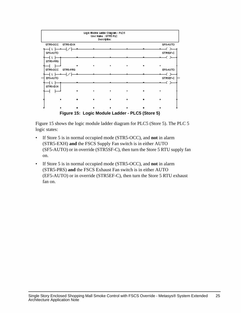
Figure 15 shows the logic module ladder diagram for PLC5 (Store 5). The PLC 5 logic states:
• If Store 5 is in normal occupied mode (STR5-OCC), and not in alarm (STR5-EXH) and the FSCS Supply Fan switch is in either AUTO (SF5-AUTO) or in override (STR5SF-C), then turn the Store 5 RTU supply fan on.
• If Store 5 is in normal occupied mode (STR5-OCC), and not in alarm (STR5-PRS) and the FSCS Exhaust Fan switch is in either AUTO (EF5-AUTO) or in override (STR5EF-C), then turn the Store 5 RTU exhaust fan on.
Figure 15: Logic Module Ladder - PLC5 (Store 5)

Single Story Enclosed Shopping Mall Smoke Control with FSCS Override - Metasys® System Extended Architecture Application Note
26
.
Figure 16 shows the logic module ladder diagram for PLC6 (Store 6). The PLC 6 logic states:
• If Store 6 is in normal occupied mode (STR6-OCC), and not in alarm (STR6-EXH) and the FSCS Supply Fan switch is in either AUTO (SF6-AUTO) or in override (STR6SF-C), then turn the Store 6 RTU supply fan on.
• If Store 6 is in normal occupied mode (STR6-OCC), and not in alarm (STR6-PRS) and the FSCS Exhaust Fan switch is in either AUTO (EF6-AUTO) or in override (STR6EF-C), then turn the Store 6 RTU exhaust fan on.
Figure 16: Logic Module Ladder - PLC6 (Store 6)

Single Story Enclosed Shopping Mall Smoke Control with FSCS Override - Metasys® System Extended Architecture Application Note
27
.
• Figure 17 shows the logic module ladder diagram for PLC7 (Mall). The PLC 7 logic states:
• If the mall area is in normal occupied mode (MALL-OCC), and not in alarm (MALL-EXH) and the FSCS Supply Fan switch is in either AUTO (MALL-AUTO) or in override (MALLSF-C), then turn the mall area supply fan on.
• If mall area is in normal occupied mode (MALL-OCC), and not in alarm (MALL-PRS) and the FSCS Exhaust Fan switch is in either AUTO (MALL-AUTO) or in override (MALLEF-C), then turn the mall area exhaust fan on.
Figure 17: Logic Module Ladder - PLC7 (Mall)

Single Story Enclosed Shopping Mall Smoke Control with FSCS Override - Metasys® System Extended Architecture Application Note
28
Smoke Control NAE ApplicationApplication File Location
This Metasys system extended architecture smoke control application is located on the Metasys Branch Purchase Package (BPP) CD in the Metasys System Extended Architecture Standard Smoke Control Applications directory.
Metasys System Extended Architecture ObjectsThis smoke control application resides on the smoke control NAE. Smoke control logic screens are created with the System Configuration Tool (SCT) to define the required Control System, Interlock, and Multiple Command objects. The Logic Connector Tool (LCT) is used to create the logic within the control system object. System points, interlocks, MCOs, and alarms are configured with the SCT.
The LCT logic is organized into two sections: Mall Control and FSCS Control.
The Mall Control section controls the automatic smoke control logic for the mall. It evaluates the inputs from the fire alarm panel and the master reset command from the FSCS to activate/inactivate the exhaust mode (DCO1) in the DX-9100 controller.
The FSCS Control section contains smoke control override logic for each of the six stores, the Mall common area, and Firefighter Control (FFC). The FSCS section contains the logic and configuration screens for each of the smoke control devices the FSCS controls and/or displays status for. These devices include Exhaust Fan 1, Supply Fan 1, Zone Switch, and Zone Smoke LED, for each store and the mall area. The Fire Fighter Control folder contains logic for the FSCS panel’s Fire Fighter Control LED and the Programming In Progress LED.

Single Story Enclosed Shopping Mall Smoke Control with FSCS Override - Metasys® System Extended Architecture Application Note
29
Mall ControlMall Logic
The main LCT logic screen for the Single Story Enclosed Shopping Mall with FSCS Override application (Figure 18), controls the automatic smoke control. It consists of the inputs, two system blocks, and outputs. The inputs (Figure 19), are one interlock for each store and the mall, and a master reset interlock. The Lock Alarms block (Figure 20) locks in the first incident. The All Stores Logic block determines which store, or the mall area, to pressurize and depressurize. Outputs (Figure 21) are binary points within a DX. Each store will have a pressurize and a depressurize (exhaust) point.
Figure 18: Logic Diagram for All Stores and Mall Area

Single Story Enclosed Shopping Mall Smoke Control with FSCS Override - Metasys® System Extended Architecture Application Note
30
The main logic for the mall is fairly large and has been broken down into smaller pieces to allow you to see the block, input, and output names. The inputs and the Lock Alarms block are shown in Figure 19. Each of the six stores and the mall area have one smoke alarm interlock. The Lock Alarms block locks in the first incident. The Master Reset Interlock releases the locked alarms. There is one output alarm for each store and one for the mall area. Only the first smoke zone in alarm (Store 1-Store 6, or the mall area) will be true. All other zones (Store 1-Store 6, or the mall area) will be false.
Figure 19: Alarm Inputs, Manual Reset, and 1st Alarm Lockout Logic

Single Story Enclosed Shopping Mall Smoke Control with FSCS Override - Metasys® System Extended Architecture Application Note
31
The Lock Alarms system block and All Store Logic system block (Figure 20) show the outputs from the Lock Alarms block feeding into the All Store Logic block, and the resulting outputs.
Figure 20: Alarm Lockout and Alarm Outputs

Single Story Enclosed Shopping Mall Smoke Control with FSCS Override - Metasys® System Extended Architecture Application Note
32
The outputs from the All Store Logic system block (Figure 21) connect to store pressurize and exhaust (depressurize) points in the DX.
All Store LogicThe All Store Logic block contains logic for each store and the mall area, and determines which store, or the mall area, to pressurize and depressurize.Outputs (Figure 21) are binary points within a DX. The expanded logic for each store and the mall area are explained in the following figures. See Figure 2 for an example of a mall area alarm, and Figure 3 for an example of a store alarm. A value of True enables the logic.
Figure 21: Alarm Outputs to Controllers
Single Story Enclosed Shopping Mall Smoke Control with FSCS Override - Metasys® System Extended Architecture Application Note
33
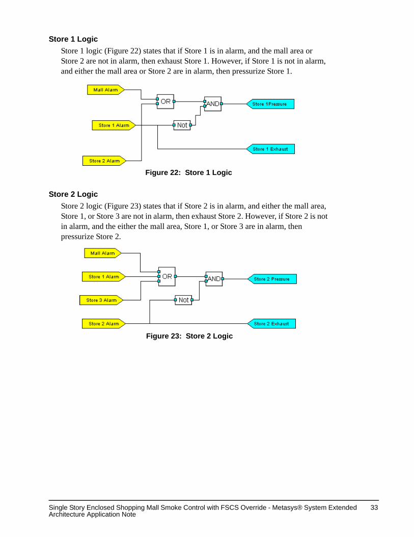
Store 1 LogicStore 1 logic (Figure 22) states that if Store 1 is in alarm, and the mall area or Store 2 are not in alarm, then exhaust Store 1. However, if Store 1 is not in alarm, and either the mall area or Store 2 are in alarm, then pressurize Store 1.
Store 2 LogicStore 2 logic (Figure 23) states that if Store 2 is in alarm, and either the mall area, Store 1, or Store 3 are not in alarm, then exhaust Store 2. However, if Store 2 is not in alarm, and the either the mall area, Store 1, or Store 3 are in alarm, then pressurize Store 2.
Figure 22: Store 1 Logic
Figure 23: Store 2 Logic

Single Story Enclosed Shopping Mall Smoke Control with FSCS Override - Metasys® System Extended Architecture Application Note
34
Store 3 LogicStore 3 logic (Figure 24) states that if Store 3 is in alarm, and either the mall area or Store 2 are not in alarm, then exhaust Store 3. However, if Store 2 is not in alarm, and the either the mall area, Store 1, or Store 3 are in alarm, then pressurize Store 2.
Store 4 LogicStore 4 logic (Figure 25) states that if Store 4 is in alarm, and either the mall area or Store 5 are not in alarm, then exhaust Store 4. However, if Store 4 is not in alarm, and the either the mall area or Store 5 are in alarm, then pressurize Store 4.
Figure 24: Store 3 Logic
Figure 25: Store 4 Logic
Single Story Enclosed Shopping Mall Smoke Control with FSCS Override - Metasys® System Extended Architecture Application Note
35
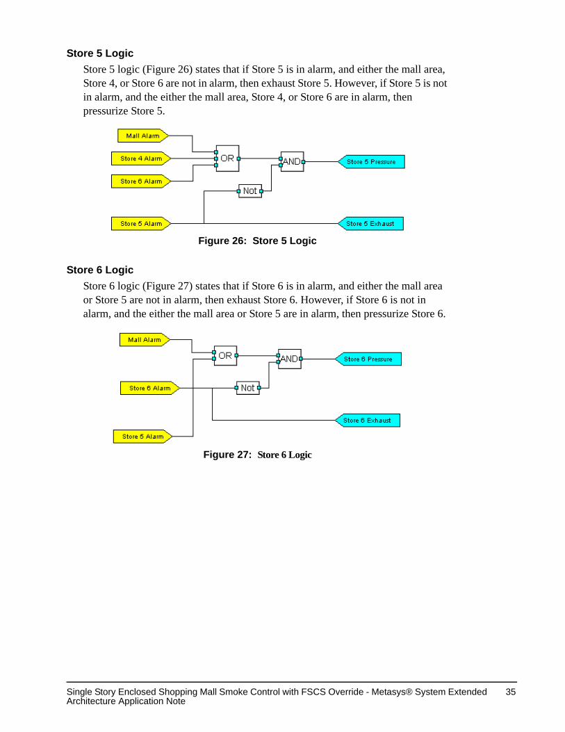
Store 5 LogicStore 5 logic (Figure 26) states that if Store 5 is in alarm, and either the mall area, Store 4, or Store 6 are not in alarm, then exhaust Store 5. However, if Store 5 is not in alarm, and the either the mall area, Store 4, or Store 6 are in alarm, then pressurize Store 5.
Store 6 LogicStore 6 logic (Figure 27) states that if Store 6 is in alarm, and either the mall area or Store 5 are not in alarm, then exhaust Store 6. However, if Store 6 is not in alarm, and the either the mall area or Store 5 are in alarm, then pressurize Store 6.
Figure 26: Store 5 Logic
Figure 27: Store 6 Logic

Single Story Enclosed Shopping Mall Smoke Control with FSCS Override - Metasys® System Extended Architecture Application Note
36
Mall LogicMall logic (Figure 28) states that if the mall area is in alarm, and either the Store 1, Store 2, Store 3, Store 4, Store 5, or Store 6 are not in alarm, then exhaust the mall area. However, if the mall area is not in alarm, and Store 1, Store 2, Store 3, Store 4, Store 5, or Store 6 is in alarm, then pressurize the mall area.
Alarm LockoutAlarm Lockout uses an Interlock object type with a True/False state. When there are no alarms, each zone has a lockout state of False. When the first zone (store) goes into alarm, all other zones (stores) are commanded to a True state. The Alarm lockout interlock definition for Store 2 (Figure 29) shows the logic used when Store 2 is the first zone in alarm. The True/False values for all other zones are locked to a state of True which prevents them from being overridden, unless commanded by the Master Reset Interlock.
Figure 28: Mall Logic
Figure 29: Store 2 Alarm Lockout Interlock Definition

Single Story Enclosed Shopping Mall Smoke Control with FSCS Override - Metasys® System Extended Architecture Application Note
37
The Master Reset Interlock (Figure 30) releases the locked alarms when commanded by the IFC fire panel Reset button.
The Master Reset Interlock Action Table (Figure 31) sets the Master Reset to Off after the last locked alarm is released.
Lockout LogicThe Alarm Lockout logic for Store 1 (Figure 32) is the same for each store and the mall area. The only difference is the name in the lockout tab of the logic.
Figure 30: Master Reset Interlock Definition
Figure 31: Master Reset Interlock Action Table
Figure 32: Lockout Logic for Store 1

Single Story Enclosed Shopping Mall Smoke Control with FSCS Override - Metasys® System Extended Architecture Application Note
38
FSCS ControlThe FSCS Control section contains logic for each of the six stores, the mall common area, and Fire Fighter Control. The mall common area and each store have their own Zone Interlock Definition, Zone Switch, Exhaust Fan 1, Supply Fan 1, and the Zone Smoke LED logic and configuration screens.
Note: The FSCS logic for each store and the mall area is the same, with the only difference being the store name. Store 2 is used as an example here.
The term zone, as used in the logic names, means the same as store. Zone 2 is the same as Store 2. Store 2 Exhaust Fan 1 is shown as Exhaust Fan 2-1.
FSCS Store 2 Smoke Interlock DefinitionThe FSCS Store 2 (Zone 2) Smoke Interlock Definition (Figure 33) includes the Store 2 IFC Zone Interlock and a point for an optional third-party zone interlock.
Table 5: IFC Point State Table
The Store 2 IFC Zone Interlock Definition (Figure 34) includes all zones for Store 2.
BACnet Point State NAE Point StateState 1 - Normal State 1 - NormalState 2 - Active Alarm State 2 - Active AlarmState 3 - Fault State 3 - FaultState 4 - Disable State 4 - Unreliable
Figure 33: Zone 2 Smoke Interlock Definition
Figure 34: IFC Zone Interlock Definition

Single Story Enclosed Shopping Mall Smoke Control with FSCS Override - Metasys® System Extended Architecture Application Note
39
3rd Party Zone Interlock DefinitionThe 3rd Party Zone Interlock Definition (Figure 35) includes a point for a optional third-party, normally open (N.O.) contact input connection.
FSCS Zone Switch LogicThe Zone Switch main logic inputs (Figure 36) from the FSCS are Zone Pressurize, Zone Depressurize, Zone Purge, and Firefighter Control switch. Inputs from the DX are Zone Pressurize and Zone Depressurize. Outputs are the Pressurize, Auto, Depressurize, and Purge LEDs on the FSCS panel and the Zone MCO.
The Zone Control system block logic (Figure 37) controls the FSCS Zone LEDs for the zone, depending on the Fire Fighter Control Key setting.
The Pressurize, Depressurize, and Purge settings on the FSCS panel are not functional unless the Fire Fighter Control Key has been turned on. If the Fire Fighter Control Key is off, the FSCS Request will be set to 0.
The Purge LED is lit if the pressurize and depressurize points in the DX are true.
The Pressurize LED is lit if the DX pressurize point is true and the depressurize point is false.
Figure 35: 3rd Party Zone Interlock Definition
Figure 36: Zone Control Switch Main Logic

Single Story Enclosed Shopping Mall Smoke Control with FSCS Override - Metasys® System Extended Architecture Application Note
40
The Depressurize LED is lit if the DX depressurize point is false and the pressurize point is true.
The Auto LED is lit only if the Zone Switch on the FSCS panel is not set to Pressurize, Depressurize, or Purged.
Figure 37: Zone Control Block Logic
Single Story Enclosed Shopping Mall Smoke Control with FSCS Override - Metasys® System Extended Architecture Application Note
41
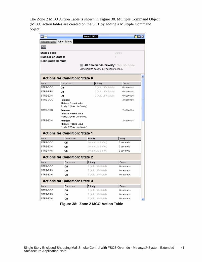
The Zone 2 MCO Action Table is shown in Figure 38. Multiple Command Object (MCO) action tables are created on the SCT by adding a Multiple Command object.
Figure 38: Zone 2 MCO Action Table

Single Story Enclosed Shopping Mall Smoke Control with FSCS Override - Metasys® System Extended Architecture Application Note
42
The FSCS Zone Switch setting determines the state value (Table 6), which in turn determines the smoke control action.
The Zone 2 Pressurize MCO Action Table is shown in Figure 39.
Table 6: FSCS Zone Switch State Value FSCS Zone Switch Position State Value Smoke Control ActionPressurize 1 Zone’s Supply Fan On Auto 0 AutoDepressurize 2 Zone’s Exhaust Fan OnPurge 3 Zone’s Supply Fan On
Zone’s Exhaust Fan On
Figure 39: Zone 2 Pressurize MCO Action Table

Single Story Enclosed Shopping Mall Smoke Control with FSCS Override - Metasys® System Extended Architecture Application Note
43
The Zone 2 Depressurize MCO Action Table is shown in Figure 40.
Figure 40: Zone 2 Depressurize MCO Action Table

Single Story Enclosed Shopping Mall Smoke Control with FSCS Override - Metasys® System Extended Architecture Application Note
44
FSCS Store 2 Exhaust Fan 1 LogicThe Store 2 Exhaust Fan 1 main logic is shown in Figure 41. Inputs from the DX are the Fan Commanded State, Fan Present Value, Zone Pressurize Command, and Zone Depressurize Command. Inputs from the FSCS are the On and Off toggle switch and the Fire Fighter Control Key. Outputs are the On, Auto, Off, and Trouble LEDs on the FSCS and an MCO that commands the DX points.
Figure 41: Exhaust Fan 1 Main Logic

Single Story Enclosed Shopping Mall Smoke Control with FSCS Override - Metasys® System Extended Architecture Application Note
45
The Exhaust Fan 1 expanded main logic (Figure 42) consists of two control blocks. The FSCS block controls the LEDs on the FSCS panel and commands the DX. The Fan Trouble Control block sets the Trouble LED.
Figure 42: Exhaust Fan 1 FSCS and Fan Trouble Control Logic
Single Story Enclosed Shopping Mall Smoke Control with FSCS Override - Metasys® System Extended Architecture Application Note
46
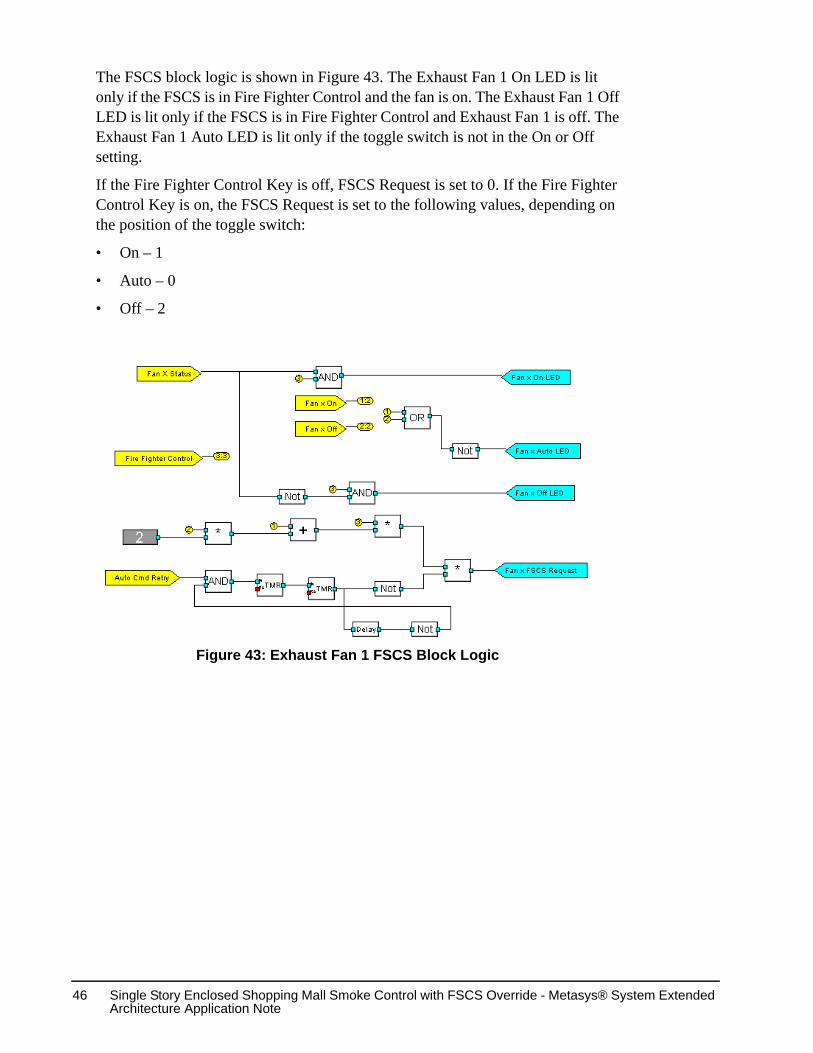
The FSCS block logic is shown in Figure 43. The Exhaust Fan 1 On LED is lit only if the FSCS is in Fire Fighter Control and the fan is on. The Exhaust Fan 1 Off LED is lit only if the FSCS is in Fire Fighter Control and Exhaust Fan 1 is off. The Exhaust Fan 1 Auto LED is lit only if the toggle switch is not in the On or Off setting.
If the Fire Fighter Control Key is off, FSCS Request is set to 0. If the Fire Fighter Control Key is on, the FSCS Request is set to the following values, depending on the position of the toggle switch:
• On – 1
• Auto – 0
• Off – 2
Figure 43: Exhaust Fan 1 FSCS Block Logic

Single Story Enclosed Shopping Mall Smoke Control with FSCS Override - Metasys® System Extended Architecture Application Note
47
The Fan Trouble Control block logic is shown in Figure 44. The Exhaust Fan 1 Trouble LED is lit if the fan is in smoke control and the fan has not reached its desired setpoint within 60 seconds or one of the DX fuses has blown. A fan is in smoke control if, either the DX is in pressurize or depressurize mode, or, the Fire Fighter Control Key is on and the FSCS Exhaust Fan 1 toggle switch is set to On or Off.
The Exhaust Fan 2-1 Trouble Interlock Definition (Figure 45) sets the values that, when reached, trigger a trouble alarm. The definition includes status and reliability points for the DX AO Fuse, BI Fuse, exhaust fan reliability, and the DX offline status.
Figure 44: Exhaust Fan 1 Fan Trouble Control Block Logic
Figure 45: Exhaust Fan 2-1 Trouble Interlock Definition

Single Story Enclosed Shopping Mall Smoke Control with FSCS Override - Metasys® System Extended Architecture Application Note
48
The Exhaust Fan 2-1 MCO Action Table is shown in Figure 46. The Exhaust Fan Auto point is a binary point in the DX to indicate that the Fan is under automatic smoke control. When a fire fighter turns the fan on or off, the Exhaust Fan Auto point is turned off. The Exhaust Fan Command is a point in the DX to control the fan.
The FSCS Exhaust Fan 1 toggle switch setting (Table 7) determines the state value, which in turn determines the smoke control action.Table 7: FSCS Exhaust Fan 1 Switch State Value FSCS Exhaust Fan 1 Toggle Switch Position
State Value Smoke Control Action
On 1 DepressurizeAuto 0 AutoOff 2 Exhaust Fan 1 Off
Figure 46: Exhaust Fan 2-1 MCO Action Table

Single Story Enclosed Shopping Mall Smoke Control with FSCS Override - Metasys® System Extended Architecture Application Note
49
FSCS Store 2 Supply Fan 1 LogicThe FSCS Store 2 Supply Fan 1 (Figure 47) inputs from the DX are the Fan Commanded State, Fan Present Value, Zone Pressurize Command, and Zone Depressurize Command. Inputs from the FSCS are the On and Off toggle switch and the Fire Fighter Control Key. Outputs are the On, Auto, Off, and Trouble LEDs on the FSCS and an MCO that will command the DX points.
Figure 47: Supply Fan 1 Main Logic

Single Story Enclosed Shopping Mall Smoke Control with FSCS Override - Metasys® System Extended Architecture Application Note
50
The Supply Fan 1 expanded main logic (Figure 48) consists of two control blocks. The FSCS block controls the LEDs on the FSCS panel and commands the DX. The Fan Trouble Control block sets the Supply Fan 1 Trouble LED.
Figure 48: Supply Fan 1 FSCS and Fan Trouble Control Main Logic

Single Story Enclosed Shopping Mall Smoke Control with FSCS Override - Metasys® System Extended Architecture Application Note
51
The FSCS block logic is shown in Figure 49. The Supply Fan 1 On LED is lit only if the FSCS is in Fire Fighter Control and the fan is on. The Supply Fan 1 Off LED is lit only if the FSCS is in Fire Fighter Control and the supply fan is off. The Supply Fan 1 Auto LED is lit only if the toggle switch is not in the On or Off setting.
If the Fire Fighter Control Key is off, FSCS Request is set to 0. If the Fire Fighter Control Key is on, FSCS Request is set to the values shown in Table 8, depending on the position of the toggle switch.Table 8: Supply Fan Switch FSCS Request FSCS Supply Fan Toggle Switch Position
FSCS Request Value Smoke Control Action
On 1 Pressurize Auto 0 AutoOff 2 Supply Fan Off
Figure 49: Supply Fan 1 FSCS Logic

Single Story Enclosed Shopping Mall Smoke Control with FSCS Override - Metasys® System Extended Architecture Application Note
52
The Fan Trouble Control block logic is shown in Figure 50. The Supply Fan 1 Trouble LED is lit if the fan is in smoke control and the fan has not reached its desired setpoint within 60 seconds or one of the DX fuses has blown. A fan is in smoke control if, either the DX is in pressurize or depressurize mode, or, the Fire Fighter Control Key is on and the FSCS Supply Fan 1 toggle switch is set to On or Off.
The Supply Fan 1 Interlock Definition (Figure 51) sets the values that, when reached, trigger a trouble alarm. The definition includes status and reliability points for the DX AO Fuse, BI Fuse, supply fan reliability, and the DX offline status.
Figure 50: Supply Fan 1 Fan Trouble Control Logic
Figure 51: Supply Fan 2-1 Trouble Interlock Definition

Single Story Enclosed Shopping Mall Smoke Control with FSCS Override - Metasys® System Extended Architecture Application Note
53
The Supply Fan 1 MCO Action Table is shown in Figure 52. The Supply Fan Auto point is a binary point in the DX to indicate that the fan is under automatic smoke control. When a fire fighter turns the fan on or off, the Supply Fan Auto point is turned off. The Supply Fan Command is a point in the DX to control the fan. MCO action tables are created on the SCT by adding a Multiple Command object.
The FSCS Supply Fan toggle switch setting (Table 9) determines the state value, which in turn determines the smoke control action.Table 9: FSCS Supply Fan 1 Switch State Value FSCS Supply Fan 1 Toggle Switch Position
State Value Smoke Control Action
On 1 PressurizeAuto 0 AutoOff 2 Supply Fan 1 Off
Figure 52: Supply Fan 1 MCO Action Table

Single Story Enclosed Shopping Mall Smoke Control with FSCS Override - Metasys® System Extended Architecture Application Note
54
FSCS Zone Smoke LED LogicThe Floor 2 Zone Smoke LED main logic (Figure 53) controls the Zone 2 Smoke LED on the FSCS.
The Zone Smoke expanded logic (Figure 54) has the following logic:
• If the zone is in smoke control turn the FSCS Smoke LED on solid.
• If the panel status is bad, flash the FSCS Smoke LED.
Figure 53: Zone Smoke LED Main Logic
Figure 54: Zone Smoke Block Logic

Single Story Enclosed Shopping Mall Smoke Control with FSCS Override - Metasys® System Extended Architecture Application Note
55
Zone Smoke LED - IFC Zone Detector Trouble Interlock DefinitionThe IFC Zone Detector Trouble Interlock Definition (Figure 55) contains a point for each detector in the mall. When a detector goes into alarm the FSCS Trouble LED for that zone is illuminated.
Zone Smoke LED - IFC Zone Trouble Interlock DefinitionThe IFC Zone Trouble Interlock Definition (Figure 56) contains a point for the present state and reliability of the zone, and a point for the IFC Zone Detector Trouble.
Table 10: IFC Point State TableBACnet Point State NAE Point StateState 1 - Normal State 1 - NormalState 2 - Active Alarm State 2 - Active AlarmState 3 - Fault State 3 - FaultState 4 - Disable State 4 - Unreliable
Figure 55: IFC Zone Detector Interlock Definition
Figure 56: IFC Zone Trouble Interlock Definition

Single Story Enclosed Shopping Mall Smoke Control with FSCS Override - Metasys® System Extended Architecture Application Note
56
Zone Smoke LED - 3rd Party Zone Trouble Interlock DefinitionThe 3rd Party Zone Trouble Interlock Definition (Figure 57) contains an optional, third-party, normally open (N.O.) contact input connection, and a point to monitor the DX offline status. If the third party point goes unreliable or the DX monitoring the third party point goes offline, the Zone LED is lit.
Figure 57: 3rd Party Zone Trouble Interlock Definition
Published in U.S.A. www.johnsoncontrols.com
Controls Group507 E. Michigan StreetMilwaukee, WI 53202
Metasys® is a registered trademark of Johnson Controls, Inc.All other marks herein are the marks of their respective owners.
© 2005 Johnson Controls, Inc.
Single Story Enclosed Shopping Mall Smoke Control with FSCS Override - Metasys® System Extended Architecture Application Note
57
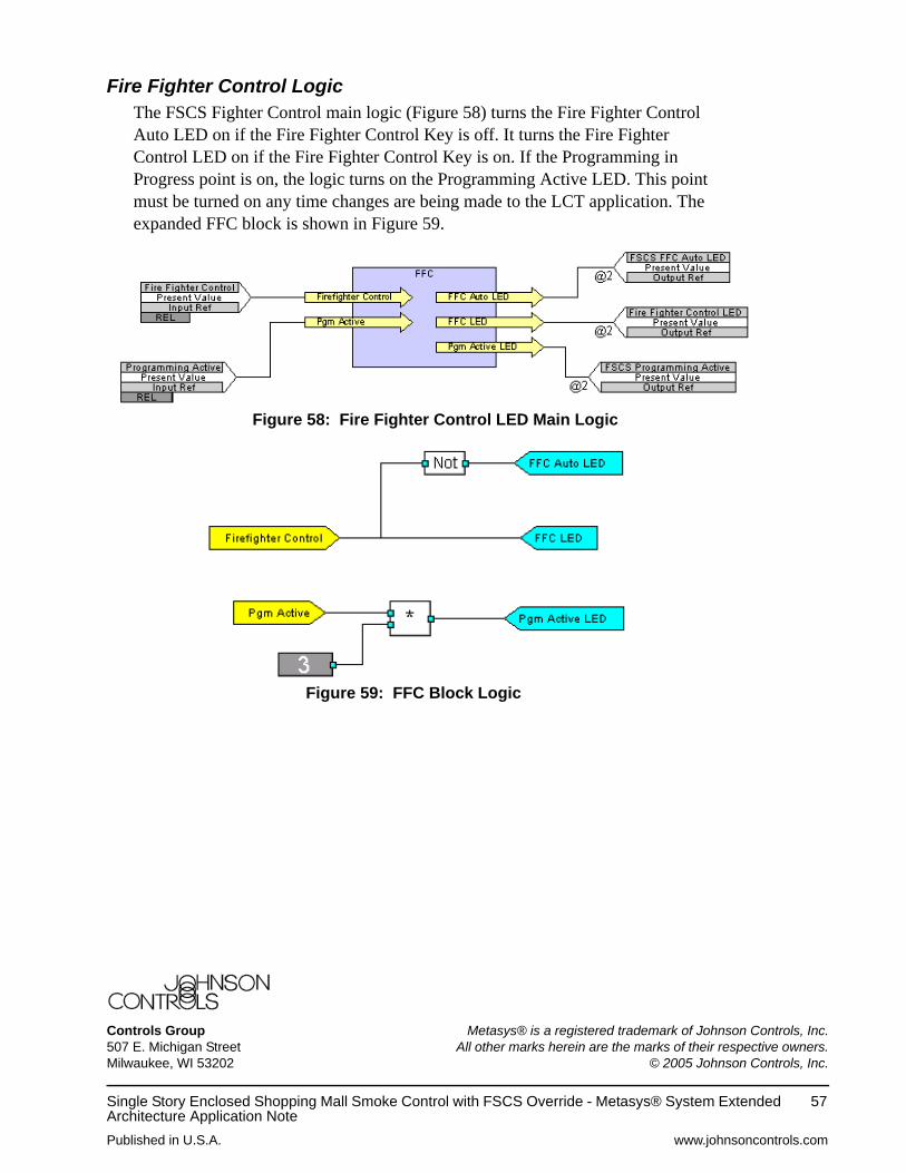
Fire Fighter Control LogicThe FSCS Fighter Control main logic (Figure 58) turns the Fire Fighter Control Auto LED on if the Fire Fighter Control Key is off. It turns the Fire Fighter Control LED on if the Fire Fighter Control Key is on. If the Programming in Progress point is on, the logic turns on the Programming Active LED. This point must be turned on any time changes are being made to the LCT application. The expanded FFC block is shown in Figure 59.
Figure 58: Fire Fighter Control LED Main Logic
Figure 59: FFC Block Logic