SiNglE-PhaSE MOTORS - AsEG Antriebstechnik · Single-phase motors with one single capacitor...
14
63 SINGLE-PHASE MOTORS - TECHNICAL CATALOGUE 1039/12 SINGLE-PHASE MOTORS
Transcript of SiNglE-PhaSE MOTORS - AsEG Antriebstechnik · Single-phase motors with one single capacitor...
63SinGle-PHaSe motorS - TEChNiCal CaTalOguE 1039/12
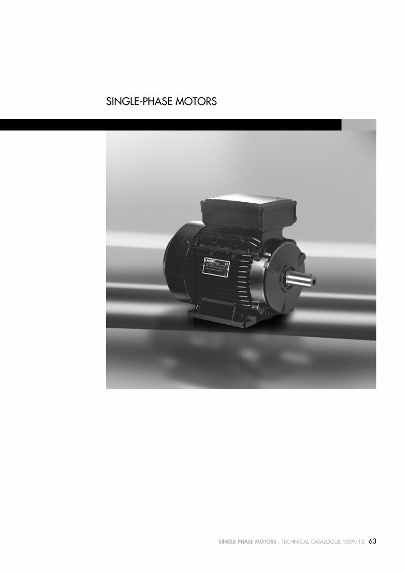
SiNglE-PhaSE MOTORS

64 SinGle-PHaSe motorS - TEChNiCal CaTalOguE 1039/12
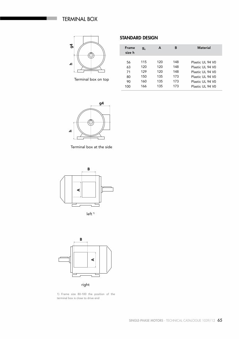
TERMiNal BOx
The location of the terminal box (viewed from drive end) in standard design is on top; on the right or on the left are possible.
For motors with mountings IM B6, IM B7, IM B8, IM V5, IM V6 the location of the terminal box is related to an IM B3 mounting.
The position of the entry openings can be adjusted to suit the existing connection facilities by turning through 90°. Should special accessories be used (temperature detectors, anti-condensation heating, etc.) please enquire.
For motors in standard design, the cable gland does not belong to our scope of delivery.
The dimension tables always show the maximum distance to the outermost edge of the available terminal boxes. This maximum value may, however, be smaller, depending on the design of the terminal box. If the space for mounting is very limited, please enquire.
Direction of cable entries
frame size Degree of Max. external protection thread for cable entry cable diam.
Metric 1) Pg 2) mm
56 - 71 IP 55 1 x M16 1 x Pg 11 12 80 -100 IP 55 1 x M20 1 x Pg 13.5 16
1) Pitch 1.52) Pg thread to DIN 40 430 (on request)
65SinGle-PHaSe motorS - TEChNiCal CaTalOguE 1039/12
TERMiNal BOx
1) Frame size 80-100 the position of the terminal box is close to drive end
Terminal box on top
BA
g4
h
Terminal box at the side
A
B g4
h
left 1)
B
A
g4
h
right
A
B g4
h
Standard deSiGn
frame g4 A B Material size h
56 115 120 148 Plastic UL 94 V0 63 120 120 148 Plastic UL 94 V0 71 129 120 148 Plastic UL 94 V0 80 150 135 173 Plastic UL 94 V0 90 160 135 173 Plastic UL 94 V0 100 166 135 173 Plastic UL 94 V0
66 SinGle-PHaSe motorS - TEChNiCal CaTalOguE 1039/12
CONNECTiON DiagRaMS
MAIN
MAIN
MAIN
Connection at high voltage rate
AUXILIARY
RUNNING CAPACITOR
Connection at low voltage rate
MAIN
AUXILIARY
RUNNING CAPACITOR
N
L
N
L
SERIES AMD
MAINMAIN
MAIN
N
L
AUXILIARY
MAIN
SExx
CAPACITORSTARTING
Connection at high voltage rate
CAPACITORRUNNING
Connection at low voltage rate
CAPACITORRUNNING
CAPACITORSTARTING
SExx
AUXILIARY
N
L
SERIES AMDE
for connection of starting capacitorSExx - electronic device
AUXILIARY
RUNNING CAPACITOR
MAIN
N
LA
AUXILIARY
MAIN
SExx
CAPACITORSTARTING
CAPACITORRUNNING
LI
N
SERIES AMM
for connection of starting capacitorSExx - electronic device
AUXILIARY
RUNNING CAPACITOR
MAIN
N
LA
AUXILIARY
MAIN
SExx
CAPACITORSTARTING
CAPACITORRUNNING
LI
N
SERIES AMME
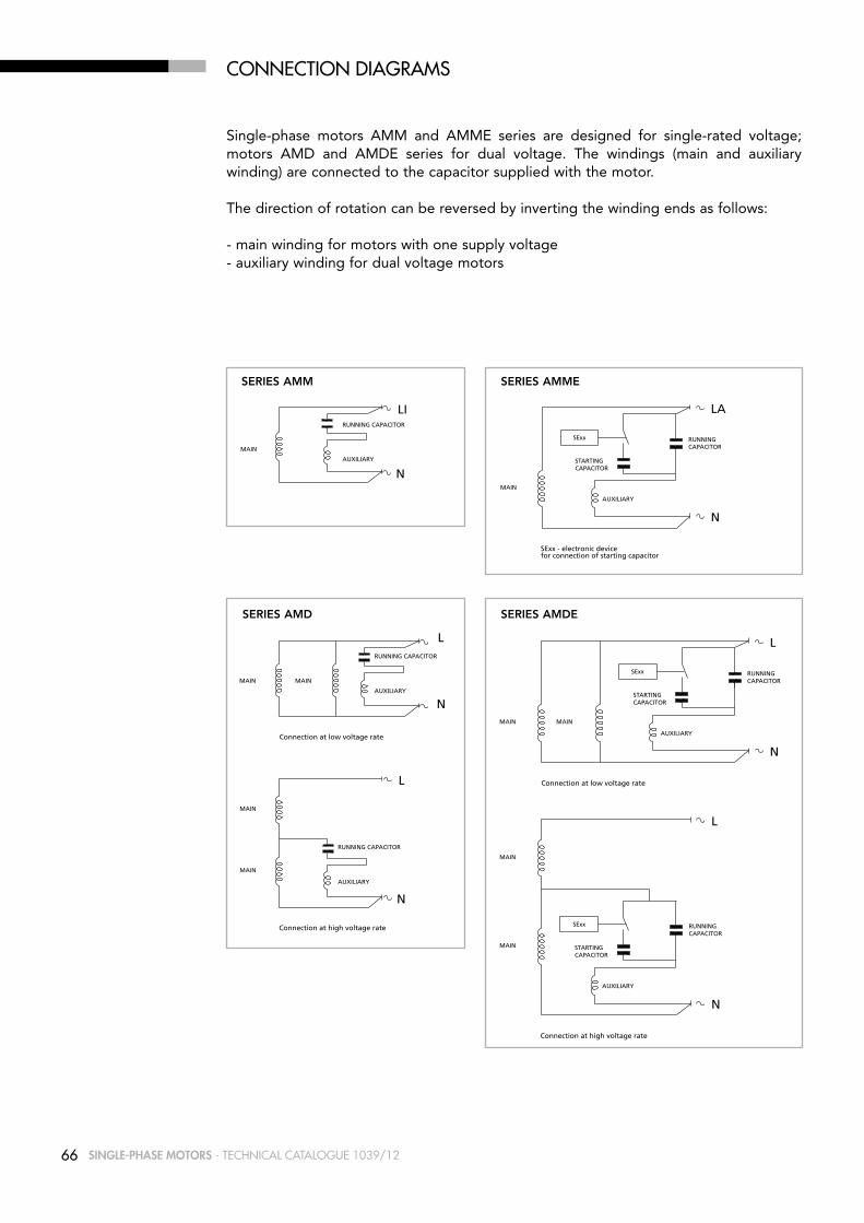
Single-phase motors AMM and AMME series are designed for single-rated voltage; motors AMD and AMDE series for dual voltage. The windings (main and auxiliary winding) are connected to the capacitor supplied with the motor.
The direction of rotation can be reversed by inverting the winding ends as follows:
- main winding for motors with one supply voltage- auxiliary winding for dual voltage motors
67SinGle-PHaSe motorS - TEChNiCal CaTalOguE 1039/12
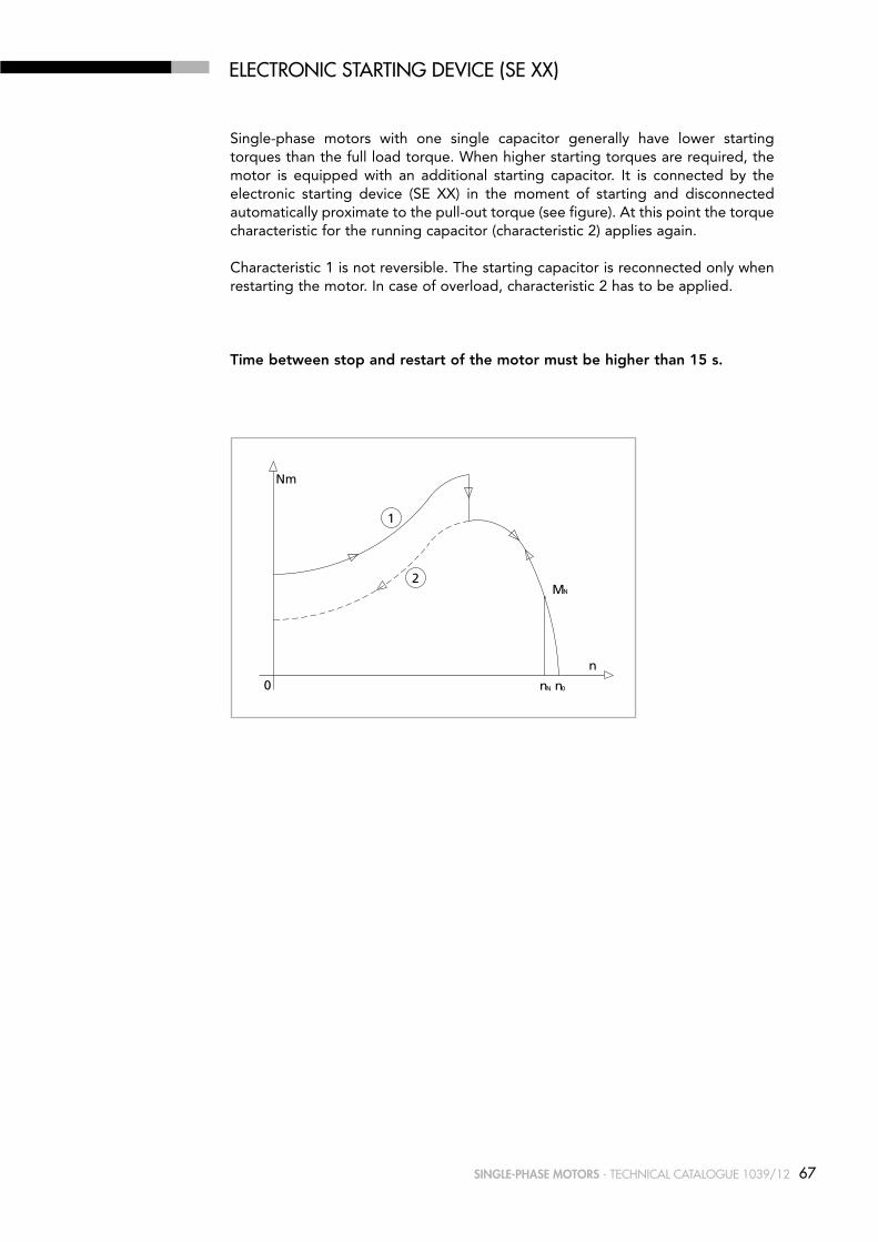
ElECTRONiC STaRTiNg DEViCE (SE xx)
Single-phase motors with one single capacitor generally have lower starting torques than the full load torque. When higher starting torques are required, the motor is equipped with an additional starting capacitor. It is connected by the electronic starting device (SE XX) in the moment of starting and disconnected automatically proximate to the pull-out torque (see figure). At this point the torque characteristic for the running capacitor (characteristic 2) applies again.
Characteristic 1 is not reversible. The starting capacitor is reconnected only when restarting the motor. In case of overload, characteristic 2 has to be applied.
time between stop and restart of the motor must be higher than 15 s.
\\NTLAFERTSEGNI\SMRI\catalogo SMRI\catalogo monofase\curv-car monofase.dwg
0 0N
N
n
2
1
M
n
n
Nm
68 SinGle-PHaSe motorS - TEChNiCal CaTalOguE 1039/12
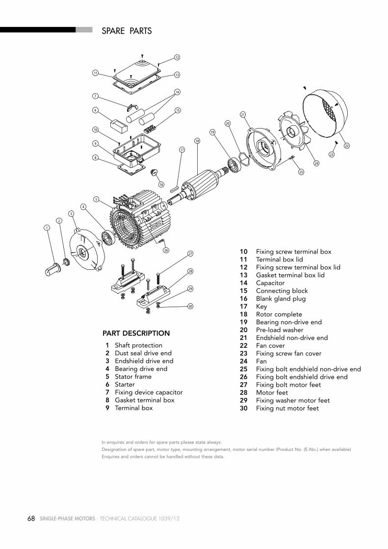
1 Shaft protection 2 Dust seal drive end 3 Endshield drive end 4 Bearing drive end 5 Stator frame 6 Starter 7 Fixing device capacitor 8 Gasket terminal box 9 Terminal box
PARt DESCRIPtIOn
In enquires and orders for spare parts please state always:
Designation of spare part, motor type, mounting arrangement, motor serial number (Product No. (E-No.) when available)
Enquires and orders cannot be handled without these data.
25
16
26
1
11
28
27
29
30
10
922
23
24
2
3
4
8
6
5
7
21
20
19
18
17
12
13
14
15
SPaRE PaRTS
10 Fixing screw terminal box 11 Terminal box lid 12 Fixing screw terminal box lid 13 Gasket terminal box lid 14 Capacitor 15 Connecting block 16 Blank gland plug 17 Key 18 Rotor complete 19 Bearing non-drive end 20 Pre-load washer 21 Endshield non-drive end 22 Fan cover 23 Fixing screw fan cover 24 Fan 25 Fixing bolt endshield non-drive end 26 Fixing bolt endshield drive end 27 Fixing bolt motor feet 28 Motor feet 29 Fixing washer motor feet 30 Fixing nut motor feet

69SinGle-PHaSe motorS - TEChNiCal CaTalOguE 1039/12
TYPE DESigNaTiON
Apart from other information, it is necessary to specify the exact type designation in all enquiries, when ordering spare parts or replacement motors or when asking for documentary information.
The type designation of our motors comprises 8 points of reference, each of which may consist of several letters and/or numerals. The meaning of each symbol can be seen from the following table. For motors not included in our standard range, special symbols may be used which are not listed here.
Examples
Ref. Meaning Description of symbols used for our motorspoint
1 Type of motor A Asynchronous motor
2 Cooling M Surface cooled with external fan, cooling fins
3 Type of motor M Single-phase motor ME Single-phase motor with starting capacitor D Single-phase dual-voltage motor DE Single-phase dual-voltage motor with starting capacitor
4 Shaft centre height 56, 63, 71, 80, 90, 100
5 Frame length Z S Mechanical dimension (short) M Mechanical dimension (medium) L Mechanical dimension (long)
6 Mechanical A design and B output value C D
7 Frame material A Aluminium frame
8 Number of poles 2 4 6

70 SinGle-PHaSe motorS - TEChNiCal CaTalOguE 1039/12
SiNglE-PhaSE MOTORS
for mainS voltaGe230 v - 50 Hz
DESigNED FOR RaNgE OF RaTED VOlTagE220-240 V ± 5% - 50 hz
Mn η cos ϕ IN IA/IN MA/MN MK/MN
type kW HP min-1 nm 100% 230v 220-240v 10-3 kgm2 kg
3000 min-1 (2 poles)
AMM 56z AA 2 0.12 0.16 2600 0.4 47 0.90 1.2 1.3 1.3 1.3 1.8 0.09 3 AMM 63z AA 2 0.18 0.25 2710 0.6 58.5 0.98 1.2 1.3 3 1.2 1.8 0.14 5 AMM 63z BA 2 0.25 0.33 2760 0.9 68.6 0.95 1.7 1.9 3.2 1 1.6 0.18 5.5 AMM 71z AA 2 0.37 0.50 2780 1.3 57.6 0.89 3.1 3.3 3.1 0.8 1.9 0.41 7.1 AMM 71z BA 2 0.55 0.75 2740 1.9 69 0.89 3.9 4.1 3.5 0.7 1.7 0.55 8.5 AMM 80z AA 2 0.75 1 2800 2.6 65 0.95 5.3 5.5 4.1 0.6 2 1.05 11.4 AMM 80z BA 2 1.1 1.5 2730 3.8 74 0.97 6.5 6.6 3.6 0.5 1.6 1.08 11.8 AMM 90S AA 2 1.1 1.5 2830 3.7 68 0.94 7.5 8 4 0.4 2 1.62 15.3 AMM 90l BA 2 1.5 2 2835 5.1 73 0.90 9.3 9.6 3.9 0.5 2.1 1.87 17.3 AMM 90l CA 2 1.8 2.5 2790 6.2 73 0.99 10.8 11.2 4 0.6 2 2.09 18.7 AMM 90l DA 2 2.2 1) 3 1) 2770 7.6 73 0.90 14.6 15.4 4.3 0.2 1.8 2.11 19.3 AMM 100l AA 2 2.2 3 2795 7.5 75 0.98 12.8 13.1 4.3 0.4 1.5 4.05 24.5
1500 min-1 (4 poles) AMM 56z AA 4 0.09 0.12 1340 0.6 45 0.89 1 1.1 1.9 0.5 1.2 0.14 3.5 AMM 63z AA 4 0.12 0.16 1385 0.8 50 0.97 1 1.1 2.8 0.7 1.5 0.27 4.5 AMM 63z BA 4 0.18 0.25 1280 1.3 50 0.97 1.6 1.7 2 0.8 1.2 0.34 4.9 AMM 71z AA 4 0.25 0.33 1270 1.9 52.1 0.89 2.5 2.7 2.4 0.7 1.5 0.82 7.2 AMM 71z BA 4 0.37 0.50 1370 2.6 62 0.88 2.8 3.1 2.9 0.8 1.2 1.08 8.5 AMM 80z AA 4 0.37 0.50 1390 2.5 60 0.96 2.8 2.9 3.2 0.5 1.9 2 9.8 AMM 80z BA 4 0.55 0.75 1390 3.8 67 0.88 4 4.2 3.2 0.5 1.8 2.41 11.3 AMM 80z CA 4 0.75 1 1445 5.0 73 0.90 4.9 5.1 4.4 0.3 1.9 2.7 12.8 AMM 90l AA 4 1.1 1.5 1415 7.4 70 0.93 7.4 7.8 3.6 0.5 1.5 3.13 15.4 AMM 90l BA 4 1.5 1) 2 1) 1430 10.0 79 0.94 9 9.3 4.3 0.5 1.7 3.73 17.6 AMM 100l AA 4 1.8 2.5 1380 12.5 70 0.96 12 12.4 3.6 0.3 1.5 5.83 22.8 AMM 100l BA 4 2.2 1) 3 1) 1450 14.5 81 0.97 12.5 12.7 4.6 0.4 1.7 6 23.8
1000 min-1 (6 poles) AMM 71z AA 6 0.18 0.25 840 2.0 48.0 0.87 1.9 2 2.7 0.8 1.6 0.90 6.3 AMM 80z AA 6 0.25 0.33 900 2.7 56 0.95 2.2 2.4 2.3 0.3 1.8 2 8.8 AMM 80z BA 6 0.37 0.50 925 3.8 60 0.96 2.8 3 2.6 0.4 1.3 2.47 10 AMM 90l AA 6 0.55 0.75 950 5.5 72 0.95 3.4 3.5 3.4 0.4 1.2 5.2 16.5 AMM 90l BA 6 0.75 1 890 8.0 71 0.96 4.8 4.9 3.2 0.5 1.5 5.85 18 AMM 100l AA 6 1.1 1.5 950 11.1 69 0.96 7.1 7.7 2.9 0.2 1.3 6.73 19 AMM 100l BA 6 1.5 1) 2 1) 870 16.5 66 0.98 10 10.2 2.5 0.4 1.4 9.43 22.5
1) Temperature rise to class F
71SinGle-PHaSe motorS - TEChNiCal CaTalOguE 1039/12
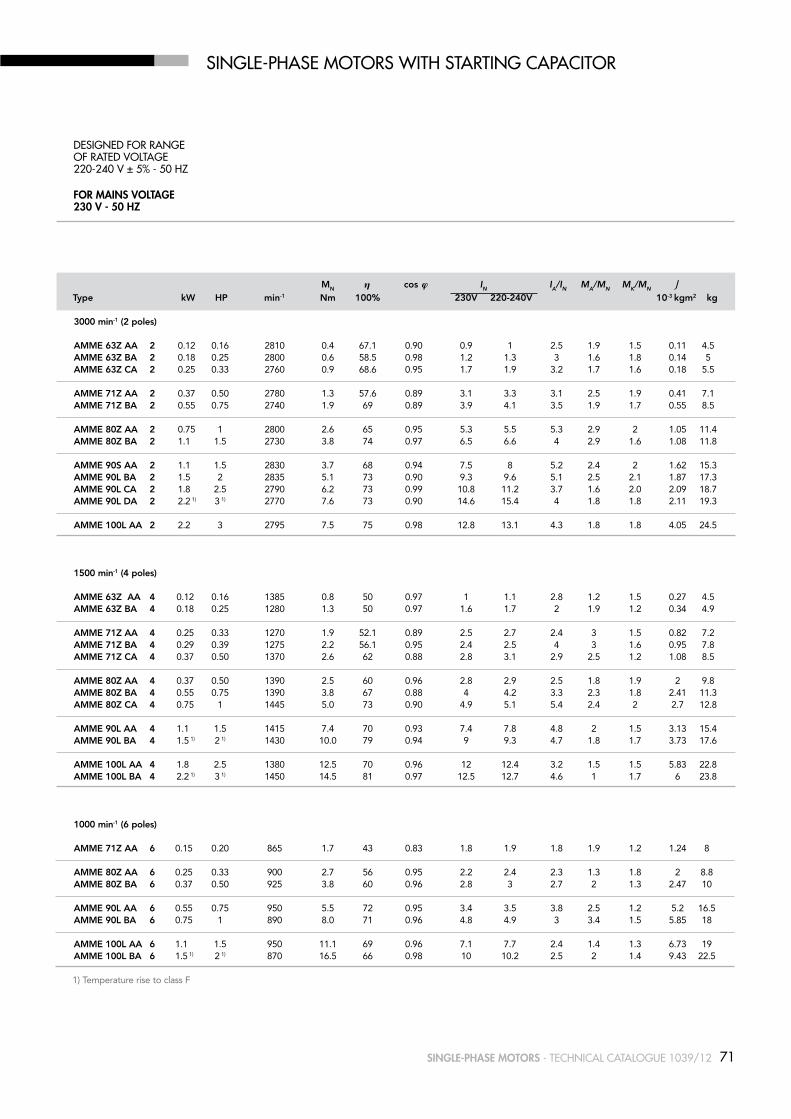
SiNglE-PhaSE MOTORS WiTh STaRTiNg CaPaCiTOR
for mainS voltaGe230 v - 50 Hz
DESigNED FOR RaNgE OF RaTED VOlTagE220-240 V ± 5% - 50 hz
Mn η cos ϕ IN IA/IN MA/MN MK/MN
type kW HP min-1 nm 100% 230v 220-240v 10-3 kgm2 kg
3000 min-1 (2 poles)
AMME 63z AA 2 0.12 0.16 2810 0.4 67.1 0.90 0.9 1 2.5 1.9 1.5 0.11 4.5 AMME 63z BA 2 0.18 0.25 2800 0.6 58.5 0.98 1.2 1.3 3 1.6 1.8 0.14 5 AMME 63z CA 2 0.25 0.33 2760 0.9 68.6 0.95 1.7 1.9 3.2 1.7 1.6 0.18 5.5 AMME 71z AA 2 0.37 0.50 2780 1.3 57.6 0.89 3.1 3.3 3.1 2.5 1.9 0.41 7.1 AMME 71z BA 2 0.55 0.75 2740 1.9 69 0.89 3.9 4.1 3.5 1.9 1.7 0.55 8.5 AMME 80z AA 2 0.75 1 2800 2.6 65 0.95 5.3 5.5 5.3 2.9 2 1.05 11.4 AMME 80z BA 2 1.1 1.5 2730 3.8 74 0.97 6.5 6.6 4 2.9 1.6 1.08 11.8 AMME 90S AA 2 1.1 1.5 2830 3.7 68 0.94 7.5 8 5.2 2.4 2 1.62 15.3 AMME 90l BA 2 1.5 2 2835 5.1 73 0.90 9.3 9.6 5.1 2.5 2.1 1.87 17.3 AMME 90l CA 2 1.8 2.5 2790 6.2 73 0.99 10.8 11.2 3.7 1.6 2.0 2.09 18.7 AMME 90l DA 2 2.2 1) 3 1) 2770 7.6 73 0.90 14.6 15.4 4 1.8 1.8 2.11 19.3 AMME 100l AA 2 2.2 3 2795 7.5 75 0.98 12.8 13.1 4.3 1.8 1.8 4.05 24.5
1500 min-1 (4 poles) AMME 63z AA 4 0.12 0.16 1385 0.8 50 0.97 1 1.1 2.8 1.2 1.5 0.27 4.5 AMME 63z BA 4 0.18 0.25 1280 1.3 50 0.97 1.6 1.7 2 1.9 1.2 0.34 4.9 AMME 71z AA 4 0.25 0.33 1270 1.9 52.1 0.89 2.5 2.7 2.4 3 1.5 0.82 7.2 AMME 71z BA 4 0.29 0.39 1275 2.2 56.1 0.95 2.4 2.5 4 3 1.6 0.95 7.8 AMME 71z CA 4 0.37 0.50 1370 2.6 62 0.88 2.8 3.1 2.9 2.5 1.2 1.08 8.5 AMME 80z AA 4 0.37 0.50 1390 2.5 60 0.96 2.8 2.9 2.5 1.8 1.9 2 9.8 AMME 80z BA 4 0.55 0.75 1390 3.8 67 0.88 4 4.2 3.3 2.3 1.8 2.41 11.3 AMME 80z CA 4 0.75 1 1445 5.0 73 0.90 4.9 5.1 5.4 2.4 2 2.7 12.8 AMME 90l AA 4 1.1 1.5 1415 7.4 70 0.93 7.4 7.8 4.8 2 1.5 3.13 15.4 AMME 90l BA 4 1.5 1) 2 1) 1430 10.0 79 0.94 9 9.3 4.7 1.8 1.7 3.73 17.6 AMME 100l AA 4 1.8 2.5 1380 12.5 70 0.96 12 12.4 3.2 1.5 1.5 5.83 22.8 AMME 100l BA 4 2.2 1) 3 1) 1450 14.5 81 0.97 12.5 12.7 4.6 1 1.7 6 23.8
1000 min-1 (6 poles)
AMME 71z AA 6 0.15 0.20 865 1.7 43 0.83 1.8 1.9 1.8 1.9 1.2 1.24 8 AMME 80z AA 6 0.25 0.33 900 2.7 56 0.95 2.2 2.4 2.3 1.3 1.8 2 8.8 AMME 80z BA 6 0.37 0.50 925 3.8 60 0.96 2.8 3 2.7 2 1.3 2.47 10 AMME 90l AA 6 0.55 0.75 950 5.5 72 0.95 3.4 3.5 3.8 2.5 1.2 5.2 16.5 AMME 90l BA 6 0.75 1 890 8.0 71 0.96 4.8 4.9 3 3.4 1.5 5.85 18 AMME 100l AA 6 1.1 1.5 950 11.1 69 0.96 7.1 7.7 2.4 1.4 1.3 6.73 19 AMME 100l BA 6 1.5 1) 2 1) 870 16.5 66 0.98 10 10.2 2.5 2 1.4 9.43 22.5
1) Temperature rise to class F

72 SinGle-PHaSe motorS - TEChNiCal CaTalOguE 1039/12
SiNglE-PhaSE Dual-VOlTagE MOTORS
for mainS voltaGe115-230 v - 50 Hz
Mn η cos ϕ IN IA/IN MA/MN MK/MN
type kW HP min-1 nm 100% 115-230v 10-3 kgm2 kg
3000 min-1 (2 poles)
AMD 63z AA 2 0.11 0.15 2760 0.4 52 0.93 2-1 2.8 0.6 1.5 0.11 4.5 AMD 63z BA 2 0.18 0.25 2800 0.6 55 0.98 2.9-1.45 3 0.5 1.6 0.14 5 AMD 63z CA 2 0.24 0.32 2815 0.8 56 0.98 3.8-1.9 3.1 0.6 1.8 0.18 5.5 AMD 71z AA 2 0.37 0.50 2730 1.3 55 0.90 6.6-3.3 3.3 0.9 2 0.41 7.1 AMD 71z BA 2 0.55 0.75 2840 1.8 64 0.94 8-4 4.2 0.5 1.9 0.55 8.5 AMD 80z AA 2 0.75 1 2800 2.6 60 0.78 13.8-7 3.5 0.4 2.1 1.05 11.4 AMD 80z BA 2 1.1 1.5 2770 3.8 72 0.93 14.2-7.2 3.5 0.5 1.6 1.08 11.8 AMD 90S AA 2 1.1 1.5 2815 3.7 70 0.78 17.5-8.8 3.8 0.4 1.9 1.62 15.3 AMD 90l BA 2 1.5 2 2800 5.1 69 0.87 22-11 3.6 0.4 1.8 1.87 17.3 AMD 90l CA 2 1.8 2.5 2810 6.1 70 0.89 25-12.5 3.7 0.3 1.9 2.09 18.7 AMD 90l DA 2 2.2 1) 3 1) 2880 7.3 76 0.93 27.2-13.6 5 0.3 1.9 2.10 19.3 AMD 100l AA 2 2.2 3 2810 7.5 75 0.92 28-14 4.6 0.2 1.8 4.05 24.5
1500 min-1 (4 poles) AMD 63z AA 4 0.11 0.15 1370 0.8 53 0.89 2.2-1.1 2 0.8 1.6 0.27 4.5 AMD 63z BA 4 0.18 0.25 1340 1.3 51 0.9 3.3-1.7 1.9 0.6 1.3 0.34 4.9 AMD 71z AA 4 0.24 0.32 1300 1.8 51 0.81 5.1-2.55 2.5 0.7 1.4 0.82 7.2 AMD 71z BA 4 0.29 0.39 1340 2.1 61 0.84 4.9-2.45 2.6 0.6 1.6 0.95 7.8 AMD 71z CA 4 0.37 0.5 1370 2.6 58 0.85 6.5-3.25 3.4 0.5 1.5 1.08 8.5 AMD 80z AA 4 0.37 0.5 1375 2.6 54 0.94 6.3-3.15 2.5 0.7 1.5 2 9.8 AMD 80z BA 4 0.55 0.75 1360 3.9 66 0.84 8.6-4.3 3.4 0.6 1.7 2.41 11.3 AMD 80z CA 4 0.75 1 1435 5.0 62 0.91 11.5-5.75 4.1 0.4 1.9 2.7 12.8 AMD 90l AA 4 1.1 1.5 1425 7.4 69 0.81 17-8.5 3.9 0.3 1.9 3.13 15.4 AMD 90l BA 4 1.5 1) 2 1) 1415 10.1 72 0.88 20.5-10.25 3.4 0.3 1.4 3.73 17.6 AMD 100l AA 4 1.8 2.5 1430 12.0 70 0.86 26-13 3.2 0.3 1.6 5.83 22.8 AMD 100l BA 4 2.2 1) 3 1) 1440 14.6 72 0.86 31-15.5 3.2 0.2 1.3 6 23.8
1000 min-1 (6 poles)
AMD 71z AA 6 0.15 0.20 910 1.6 58 0.80 2.8-1.4 2.2 0.5 1.4 1.24 8 AMD 80z AA 6 0.25 0.33 930 2.6 61 0.85 4.2-2.1 2.3 0.4 1.2 2 8.8 AMD 80z BA 6 0.37 0.50 940 3.8 61 0.82 6.4-3.2 2.9 0.4 1.6 2.47 10 AMD 90l AA 6 0.55 0.75 950 5.5 68 0.83 8.5-4.25 2.7 0.6 1.3 5.2 16.5 AMD 90l BA 6 0.75 1 950 7.5 58 0.79 14.2-7.1 3 0.4 1.6 5.85 18 AMD 100l AA 6 1.1 1.5 935 11.2 72 0.88 15-7.5 3.1 0.3 1.4 6.73 19 AMD 100l BA 6 1.5 1) 2 1) 890 16.1 74 0.98 18-9 2.9 0.5 1.4 9.43 22.5
1) Temperature rise to class F
73SinGle-PHaSe motorS - TEChNiCal CaTalOguE 1039/12
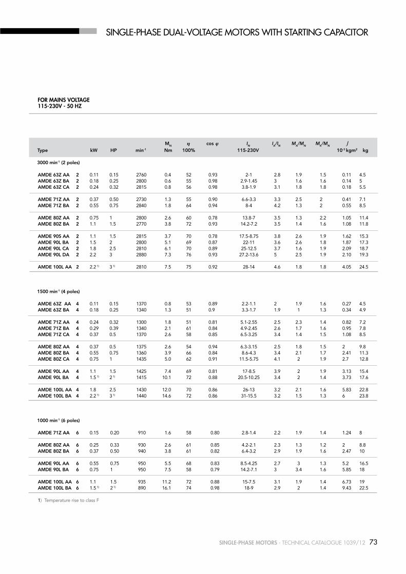
SiNglE-PhaSE Dual-VOlTagE MOTORS WiTh STaRTiNg CaPaCiTOR
Mn η cos ϕ IN IA/IN MA/MN MK/MN
type kW HP min-1 nm 100% 115-230v 10-3 kgm2 kg
3000 min-1 (2 poles)
AMDE 63z AA 2 0.11 0.15 2760 0.4 52 0.93 2-1 2.8 1.9 1.5 0.11 4.5 AMDE 63z BA 2 0.18 0.25 2800 0.6 55 0.98 2.9-1.45 3 1.6 1.6 0.14 5 AMDE 63z CA 2 0.24 0.32 2815 0.8 56 0.98 3.8-1.9 3.1 1.8 1.8 0.18 5.5 AMDE 71z AA 2 0.37 0.50 2730 1.3 55 0.90 6.6-3.3 3.3 2.5 2 0.41 7.1 AMDE 71z BA 2 0.55 0.75 2840 1.8 64 0.94 8-4 4.2 1.3 2 0.55 8.5 AMDE 80z AA 2 0.75 1 2800 2.6 60 0.78 13.8-7 3.5 1.3 2.2 1.05 11.4 AMDE 80z BA 2 1.1 1.5 2770 3.8 72 0.93 14.2-7.2 3.5 1.4 1.6 1.08 11.8 AMDE 90S AA 2 1.1 1.5 2815 3.7 70 0.78 17.5-8.75 3.8 2.6 1.9 1.62 15.3 AMDE 90l BA 2 1.5 2 2800 5.1 69 0.87 22-11 3.6 2.6 1.8 1.87 17.3 AMDE 90l CA 2 1.8 2.5 2810 6.1 70 0.89 25-12.5 3.7 1.6 1.9 2.09 18.7 AMDE 90l DA 2 2.2 3 2880 7.3 76 0.93 27.2-13.6 5 2.5 1.9 2.10 19.3 AMDE 100l AA 2 2.2 1) 3 1) 2810 7.5 75 0.92 28-14 4.6 1.8 1.8 4.05 24.5
1500 min-1 (4 poles) AMDE 63z AA 4 0.11 0.15 1370 0.8 53 0.89 2.2-1.1 2 1.9 1.6 0.27 4.5 AMDE 63z BA 4 0.18 0.25 1340 1.3 51 0.9 3.3-1.7 1.9 1 1.3 0.34 4.9 AMDE 71z AA 4 0.24 0.32 1300 1.8 51 0.81 5.1-2.55 2.5 2.3 1.4 0.82 7.2 AMDE 71z BA 4 0.29 0.39 1340 2.1 61 0.84 4.9-2.45 2.6 1.7 1.6 0.95 7.8 AMDE 71z CA 4 0.37 0.5 1370 2.6 58 0.85 6.5-3.25 3.4 1.4 1.5 1.08 8.5 AMDE 80z AA 4 0.37 0.5 1375 2.6 54 0.94 6.3-3.15 2.5 1.8 1.5 2 9.8 AMDE 80z BA 4 0.55 0.75 1360 3.9 66 0.84 8.6-4.3 3.4 2.1 1.7 2.41 11.3 AMDE 80z CA 4 0.75 1 1435 5.0 62 0.91 11.5-5.75 4.1 2 1.9 2.7 12.8 AMDE 90l AA 4 1.1 1.5 1425 7.4 69 0.81 17-8.5 3.9 2 1.9 3.13 15.4 AMDE 90l BA 4 1.5 1) 2 1) 1415 10.1 72 0.88 20.5-10.25 3.4 2 1.4 3.73 17.6 AMDE 100l AA 4 1.8 2.5 1430 12.0 70 0.86 26-13 3.2 2.1 1.6 5.83 22.8 AMDE 100l BA 4 2.2 1) 3 1) 1440 14.6 72 0.86 31-15.5 3.2 1.5 1.3 6 23.8
1000 min-1 (6 poles)
AMDE 71z AA 6 0.15 0.20 910 1.6 58 0.80 2.8-1.4 2.2 1.9 1.4 1.24 8 AMDE 80z AA 6 0.25 0.33 930 2.6 61 0.85 4.2-2.1 2.3 1.3 1.2 2 8.8 AMDE 80z BA 6 0.37 0.50 940 3.8 61 0.82 6.4-3.2 2.9 1.9 1.6 2.47 10 AMDE 90l AA 6 0.55 0.75 950 5.5 68 0.83 8.5-4.25 2.7 3 1.3 5.2 16.5 AMDE 90l BA 6 0.75 1 950 7.5 58 0.79 14.2-7.1 3 3.4 1.6 5.85 18 AMDE 100l AA 6 1.1 1.5 935 11.2 72 0.88 15-7.5 3.1 1.9 1.4 6.73 19 AMDE 100l BA 6 1.5 1) 2 1) 890 16.1 74 0.98 18-9 2.9 2 1.4 9.43 22.5
1) Temperature rise to class F
for mainS voltaGe115-230v - 50 Hz

74 SinGle-PHaSe motorS - TEChNiCal CaTalOguE 1039/12
SiNglE-PhaSE FRaME SizE 56 - 100 iM B3
GD
GA
C
K
LB
BB
B
BA
E
AL
L
AA
CA
EA
K1
A
AF AD
DB
D
LC
DA
AC
HD
AD
HAH
AB
HC
1) Clearance hole for screw2) Maximum dimension3) Centering holes in shaft extensions to DIN 332 part 2
IEC H A B C K 1) AB BB CA AD 2) HD 2) AC HC HA K1
56 56 90 71 36 6 107 86 64 116 172 110 109 8 9 63 63 100 80 40 7 120 100 72 120 183 124 120 8 11 71 71 112 90 45 8 135 108 83 134 205 139 142 9 11 80 80 125 100 50 10 153 125 89 150 230 160 162 9.5 14 90S 90 140 100 56 10 170 150 116 160 250 180 181 11 15 90l 90 140 125 56 10 170 150 91 160 250 180 181 11 15 100 100 160 140 63 11 192 166 110 166 266 196 198 12 17
IEC l lB lC Al Af BA AA D/DA E/EA f/fA gD gA/gC DB 3)
56 188 168 211 61 147 27 27 9 j6 20 3 3 10.2 M3
63 211 188 238 63 147 29 30 11 j6 23 4 4 12.5 M4 71 246 216 278 69 147 28 31 14 j6 30 5 5 16 M5 80 272 232 319 79 173 28.5 34.5 19 j6 40 6 6 21.5 M6 90S 317 267 372 85 173 28/53 37 24 j6 50 8 7 27 M8 90l 317 267 372 85 173 28/53 37 24 j6 50 8 7 27 M8 100 366 306 433 91 173 38 44 28 j6 60 8 7 31 M10
75SinGle-PHaSe motorS - TEChNiCal CaTalOguE 1039/12
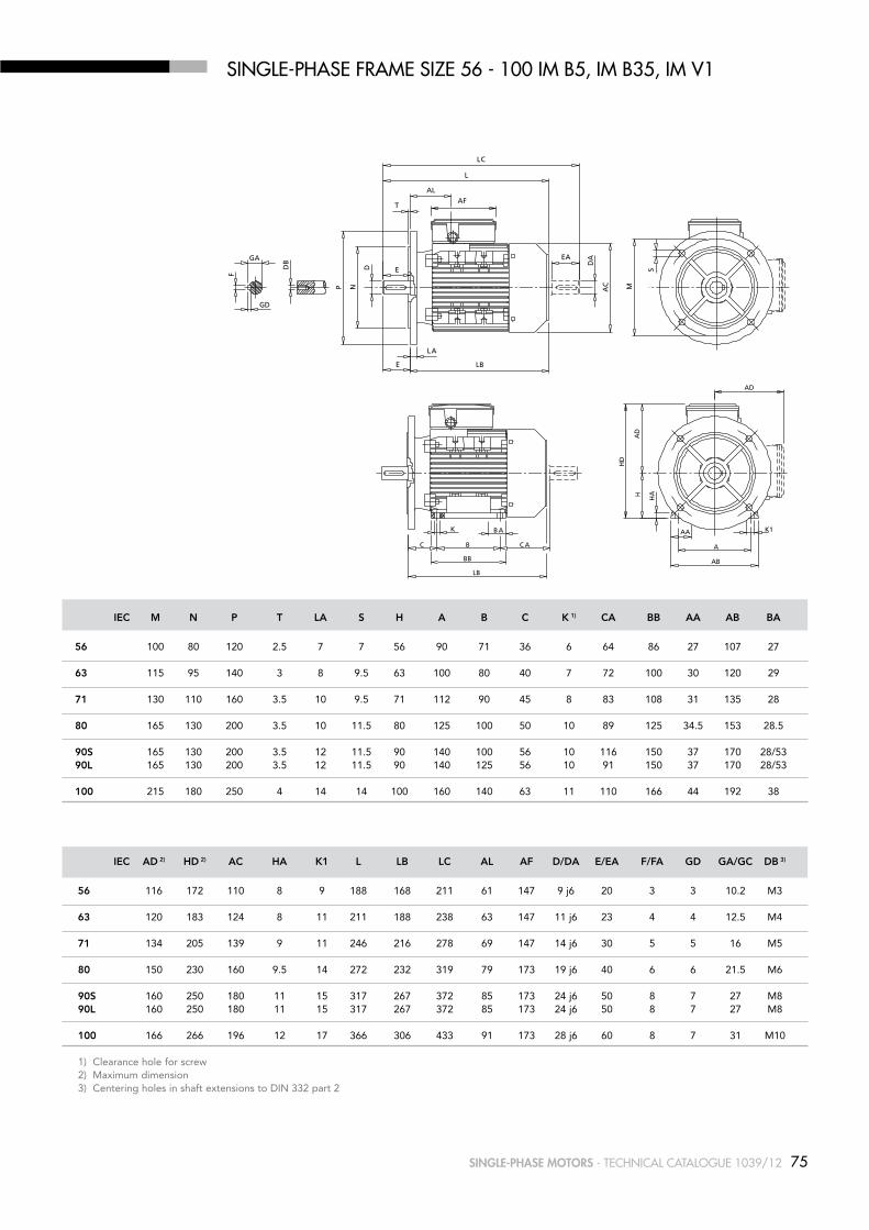
SiNglE-PhaSE FRaME SizE 56 - 100 iM B5, iM B35, iM V1
LB
E
AL
L
EA
E
LA
T
GD
GA
AF
F
DB
P N
D
DA
AC M
S
LC
K
C B
K1
C A A
AD
LB
BB AB
AABA
AD
HD
HAH
IEC AD 2) HD 2) AC HA K1 l lB lC Al Af D/DA E/EA f/fA gD gA/gC DB 3)
56 116 172 110 8 9 188 168 211 61 147 9 j6 20 3 3 10.2 M3 63 120 183 124 8 11 211 188 238 63 147 11 j6 23 4 4 12.5 M4 71 134 205 139 9 11 246 216 278 69 147 14 j6 30 5 5 16 M5 80 150 230 160 9.5 14 272 232 319 79 173 19 j6 40 6 6 21.5 M6 90S 160 250 180 11 15 317 267 372 85 173 24 j6 50 8 7 27 M8 90l 160 250 180 11 15 317 267 372 85 173 24 j6 50 8 7 27 M8 100 166 266 196 12 17 366 306 433 91 173 28 j6 60 8 7 31 M10 1) Clearance hole for screw2) Maximum dimension3) Centering holes in shaft extensions to DIN 332 part 2
IEC M n P t lA S H A B C K 1) CA BB AA AB BA
56 100 80 120 2.5 7 7 56 90 71 36 6 64 86 27 107 27 63 115 95 140 3 8 9.5 63 100 80 40 7 72 100 30 120 29 71 130 110 160 3.5 10 9.5 71 112 90 45 8 83 108 31 135 28 80 165 130 200 3.5 10 11.5 80 125 100 50 10 89 125 34.5 153 28.5 90S 165 130 200 3.5 12 11.5 90 140 100 56 10 116 150 37 170 28/5390l 165 130 200 3.5 12 11.5 90 140 125 56 10 91 150 37 170 28/53 100 215 180 250 4 14 14 100 160 140 63 11 110 166 44 192 38
76 SinGle-PHaSe motorS - TEChNiCal CaTalOguE 1039/12
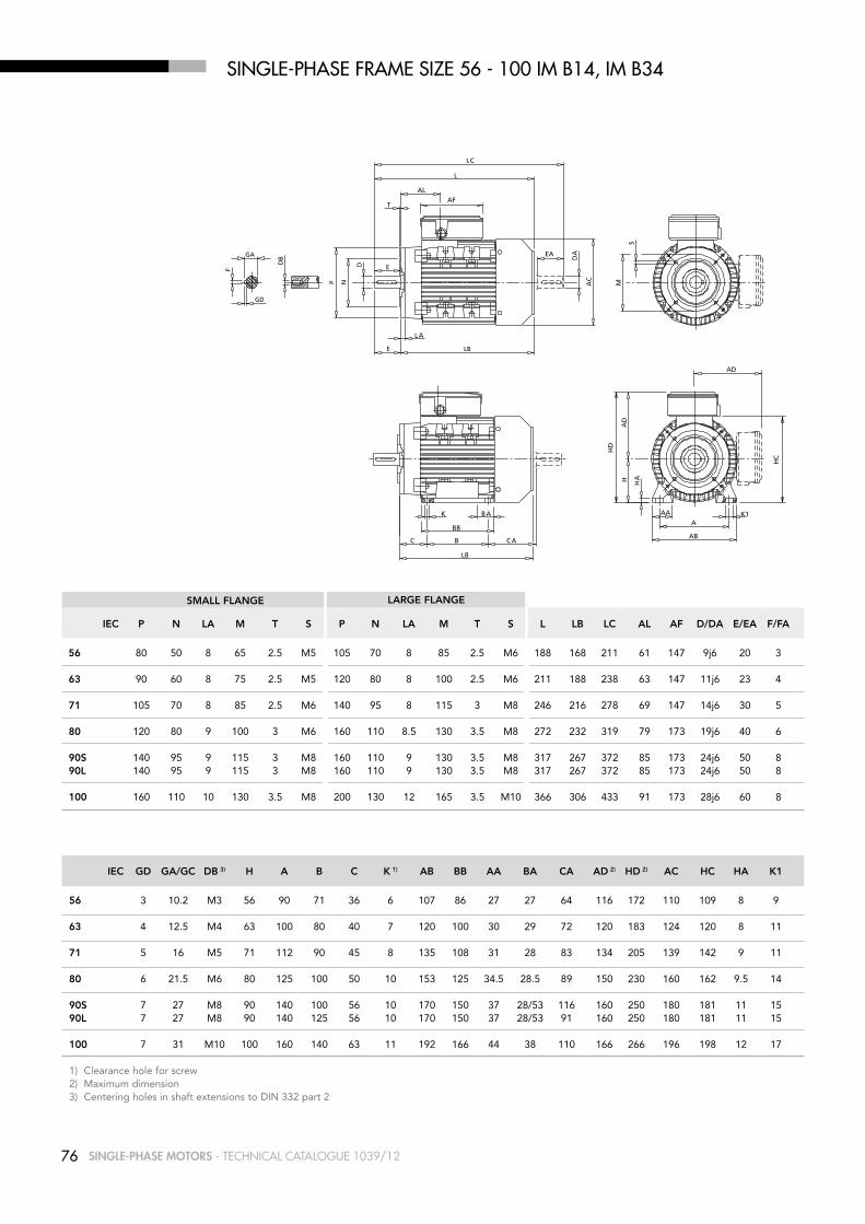
SiNglE-PhaSE FRaME SizE 56 - 100 iM B14, iM B34
E
LA
LB
LC
E
T
AL
L
EA
GD
GA
AF
DB
F
P N
D
DA
AC
M
S
K
C B C A
K1A
AB
AA
LB
BB
AD
BA
HD
AD
H HA
HC
IEC gD gA/gC DB 3) H A B C K 1) AB BB AA BA CA AD 2) HD 2) AC HC HA K1
56 3 10.2 M3 56 90 71 36 6 107 86 27 27 64 116 172 110 109 8 9 63 4 12.5 M4 63 100 80 40 7 120 100 30 29 72 120 183 124 120 8 11
71 5 16 M5 71 112 90 45 8 135 108 31 28 83 134 205 139 142 9 11
80 6 21.5 M6 80 125 100 50 10 153 125 34.5 28.5 89 150 230 160 162 9.5 14
90S 7 27 M8 90 140 100 56 10 170 150 37 28/53 116 160 250 180 181 11 1590l 7 27 M8 90 140 125 56 10 170 150 37 28/53 91 160 250 180 181 11 15
100 7 31 M10 100 160 140 63 11 192 166 44 38 110 166 266 196 198 12 17 1) Clearance hole for screw2) Maximum dimension3) Centering holes in shaft extensions to DIN 332 part 2
IEC P n lA M t S P n lA M t S l lB lC Al Af D/DA E/EA f/fA
56 80 50 8 65 2.5 M5 105 70 8 85 2.5 M6 188 168 211 61 147 9j6 20 3
63 90 60 8 75 2.5 M5 120 80 8 100 2.5 M6 211 188 238 63 147 11j6 23 4
71 105 70 8 85 2.5 M6 140 95 8 115 3 M8 246 216 278 69 147 14j6 30 5
80 120 80 9 100 3 M6 160 110 8.5 130 3.5 M8 272 232 319 79 173 19j6 40 6
90S 140 95 9 115 3 M8 160 110 9 130 3.5 M8 317 267 372 85 173 24j6 50 8 90l 140 95 9 115 3 M8 160 110 9 130 3.5 M8 317 267 372 85 173 24j6 50 8
100 160 110 10 130 3.5 M8 200 130 12 165 3.5 M10 366 306 433 91 173 28j6 60 8
SMAll flAngE lARgE flAngE