Single-element based ultra-wideband antenna array concepts ...
9
Adv. Radio Sci., 11, 297–305, 2013 www.adv-radio-sci.net/11/297/2013/ doi:10.5194/ars-11-297-2013 © Author(s) 2013. CC Attribution 3.0 License. Advances in Radio Science Single-element based ultra-wideband antenna array concepts for wireless high-precision 2-D local positioning M. Gardill, G. Fischer, R. Weigel, and A. Koelpin Friedrich-Alexander University Erlangen-Nuremberg, Institute of Electronics Engineering, Cauerstr. 9, 91054 Erlangen, Germany Correspondence to: M. Gardill ([email protected]) Abstract. We generally categorize the approaches for ultra- wideband antenna array design, and consequently propose simplified concepts for antenna arrays for a high-precision, ultra-wideband FMCW radar 2-D local positioning system to obtain robustness against multi path interference, perform angle of arrival analysis, as well as instantaneous heading estimation. We focus on low-cost and mechanical robust, industrial-application ready antennas. The antenna arrays are optimized for operation in the 5 GHz to 8 GHz frequency range and are designed towards supporting full omnidirec- tional 360 ◦ as well as partial half-plane direction of arrival estimation. Two different concepts for vehicle- as well as wall-mounted antenna array systems are proposed and dis- cussed. We propose a wideband unidirectional bow-tie an- tenna array element having 97 % impedance and 37 % pattern bandwidth and a robust vehicle mounted omnidirectional an- tenna element having more than 85 % impedance and pattern bandwidth. 1 Introduction With the allocation of the ultra-wideband (UWB) frequency range for unlicensed use by the FCC in 2002 interest in wide- band wireless systems has increased tremendously. In partic- ular wireless positioning systems based on round trip time of flight (RTOF) benefit from the large available continu- ous bandwidth, since utilizing ultra-wideband signals their reliability and accuracy can be enhanced greatly (Mahfouz et al., 2009). Whereas most commercially available UWB lo- calization systems are based on short pulses, we focus on a novel frequency-modulated continuous waveform (FMCW) concept similar to (Roehr et al., 2008), which is extended to ultra-wideband FMCW operation in the range from 5 GHz to 8 GHz and high-precision direction of arrival (DOA) esti- mation techniques using multiple coherent receive channels. This allows for high-precision and robust 2-D local position- ing of vehicles in various industrial scenarios by simultane- ously incorporating RTOF and angle of arrival (AOA) es- timations. In addition the use of a vehicular-based antenna array does allow for an instantaneous heading estimation, which cannot be achieved by single-antenna systems at all. Besides the challenges of analog integrated circuit design, such as highly-linear and broadband FMCW ramp synthesiz- ers and multiple coherent receive channels, the overall sys- tem performance is strongly dependent on the antennas. It is not enough to simply use antennas which offer a wide impedance bandwidth. Rather great care has to be taken of radiation characteristics such as a frequency stable pat- tern and a frequency- and angle-stable phase center. Subse- quently, when placing the antennas in an array, the antenna elements cannot be treated as individual sensors. Mutual cou- pling influences the feed point impedance and the array re- sponse vector, effects such as array and substrate-guided sur- face waves may emerge, and a careful and angle-dependent characterization of the array is necessary. And remembering that all those challenging effects have to be treated in a wide- band frequency range really does not simplify the work to be done. In addition, from McLean’s limit on the Q of small antennas, the inherent problem of the antenna diameter be- ing more or less dictated by λ low (Schantz, 2003), the lowest frequency of operation, but the desired distance between two antennas in an array being optimally about λ high /2, where λ high is the highest frequency of operation, best shows the slightly paradoxical design challenge in wideband antenna arrays. In addition to those electromagnetic (EM) challenges, for the addressed industrial applications the mechanical con- struction of the antennas also is of major concern. They have to be robust against vibration, moisture, dust and other Published by Copernicus Publications on behalf of the URSI Landesausschuss in der Bundesrepublik Deutschland e.V.
Transcript of Single-element based ultra-wideband antenna array concepts ...
Adv. Radio Sci., 11, 297–305, 2013www.adv-radio-sci.net/11/297/2013/doi:10.5194/ars-11-297-2013© Author(s) 2013. CC Attribution 3.0 License.
Advances inRadio Science
Single-element based ultra-wideband antenna array concepts forwireless high-precision 2-D local positioning
M. Gardill, G. Fischer, R. Weigel, and A. Koelpin
Friedrich-Alexander University Erlangen-Nuremberg, Institute of Electronics Engineering, Cauerstr. 9,91054 Erlangen, Germany
Correspondence to:M. Gardill ([email protected])
Abstract. We generally categorize the approaches for ultra-wideband antenna array design, and consequently proposesimplified concepts for antenna arrays for a high-precision,ultra-wideband FMCW radar 2-D local positioning systemto obtain robustness against multi path interference, performangle of arrival analysis, as well as instantaneous headingestimation. We focus on low-cost and mechanical robust,industrial-application ready antennas. The antenna arrays areoptimized for operation in the 5 GHz to 8 GHz frequencyrange and are designed towards supporting full omnidirec-tional 360◦ as well as partial half-plane direction of arrivalestimation. Two different concepts for vehicle- as well aswall-mounted antenna array systems are proposed and dis-cussed. We propose a wideband unidirectional bow-tie an-tenna array element having 97 % impedance and 37 % patternbandwidth and a robust vehicle mounted omnidirectional an-tenna element having more than 85 % impedance and patternbandwidth.
1 Introduction
With the allocation of the ultra-wideband (UWB) frequencyrange for unlicensed use by the FCC in 2002 interest in wide-band wireless systems has increased tremendously. In partic-ular wireless positioning systems based on round trip timeof flight (RTOF) benefit from the large available continu-ous bandwidth, since utilizing ultra-wideband signals theirreliability and accuracy can be enhanced greatly (Mahfouzet al., 2009). Whereas most commercially available UWB lo-calization systems are based on short pulses, we focus on anovel frequency-modulated continuous waveform (FMCW)concept similar to (Roehr et al., 2008), which is extended toultra-wideband FMCW operation in the range from 5 GHzto 8 GHz and high-precision direction of arrival (DOA) esti-
mation techniques using multiple coherent receive channels.This allows for high-precision and robust 2-D local position-ing of vehicles in various industrial scenarios by simultane-ously incorporating RTOF and angle of arrival (AOA) es-timations. In addition the use of a vehicular-based antennaarray does allow for an instantaneous heading estimation,which cannot be achieved by single-antenna systems at all.
Besides the challenges of analog integrated circuit design,such as highly-linear and broadband FMCW ramp synthesiz-ers and multiple coherent receive channels, the overall sys-tem performance is strongly dependent on the antennas. Itis not enough to simply use antennas which offer a wideimpedance bandwidth. Rather great care has to be takenof radiation characteristics such as a frequency stable pat-tern and a frequency- and angle-stable phase center. Subse-quently, when placing the antennas in an array, the antennaelements cannot be treated as individual sensors. Mutual cou-pling influences the feed point impedance and the array re-sponse vector, effects such as array and substrate-guided sur-face waves may emerge, and a careful and angle-dependentcharacterization of the array is necessary. And rememberingthat all those challenging effects have to be treated in a wide-band frequency range really does not simplify the work tobe done. In addition, from McLean’s limit on theQ of smallantennas, the inherent problem of the antenna diameter be-ing more or less dictated byλlow (Schantz, 2003), the lowestfrequency of operation, but the desired distance between twoantennas in an array being optimally aboutλhigh/2, whereλhigh is the highest frequency of operation, best shows theslightly paradoxical design challenge in wideband antennaarrays. In addition to those electromagnetic (EM) challenges,for the addressed industrial applications the mechanical con-struction of the antennas also is of major concern. Theyhave to be robust against vibration, moisture, dust and other
Published by Copernicus Publications on behalf of the URSI Landesausschuss in der Bundesrepublik Deutschland e.V.

298 M. Gardill et al.: Single-element based ultra-wideband antenna array concepts
Fig. 1. Localization scenario. The position of a vehicle, e.g. forklifter, is precisely estimated by using RTOF measurements. Thenovel concept of using antenna-array based systems also allowsfor AOA and instantaneous heading estimation. detail A: planar,wall- mounted antenna array; detail B: omnidirectional, vehicularmounted antenna array.
mechanical influences. And, of course, a low cost realizationis desired.
It is obvious that antenna design for the addressed high-precision positioning system is a challenging task. This paperdiscusses our advances and concepts towards UWB antennaarrays for high-precision local positioning, shows some ofour current development prototypes, and gives an overviewon future designs. The paper is organized as follows: inSect. 2, a detailed overview on the localization scenario andthe system concept is given. In chapter 3 we then discuss ourwork on ultra-wideband antenna arrays. Finally in chapter4 we draw conclusions from the preceding discussions andgive an outlook on our future work.
2 Localization scenario, system architecture, andantenna functional specification
2.1 Localization scenario
Whereas a wide range of possible applications for a high-precision wireless positioning system delivering simultane-ously range, angle, and heading information can be thoughtof, we focus, without loss of generality, on the exemplaryscenario of localizing a fork lifter in a typical industrial ware-house scenario as illustrated in Figure1. We refer to the ve-hicle whose position is to be estimated as the measurement
unit (MU) and the units supporting the measurement processas the reference units (RU). This exemplary scenario can beapplied to arbitrary positioning scenarios which obey the fol-lowing restrictions in movement between MU and RU: first,there is only a translational movement between MU and RUin the x/y-plane, i.e. the z-coordinate is fixed. Second, the ro-tational movements of the MU are restricted to rotations inthe x/y-plane, which in particular means the z and z’ axes ofthe global and MU-local coordinate systems being parallelall the time.
Several wireless local positioning system configurationshave been proposed over the last years (Gulden et al., 2009).We consider a typical RTOF scenario: Several RUs aremounted on precisely known positions in the localizationarea. In the example of Figure1, these reference units arebased on planar arrays mounted on the walls of an industrialwarehouse, as shown in detail A. The object or vehicle tobe positioned contains a MU, which is based on an arrayconfiguration capable of omnidirectional DOA estimation,as illustrated in detail B. Using a secondary FMCW radarconcept described inRoehr et al.(2008) or more detailed inRoehr(2009), the RTOF between the MU and several RUscan be measured. A sophisticated wireless synchronizationmethod ensures the necessary time-synchronous operation ofRUs and MU (Roehr et al., 2008; Roehr, 2009). Based on theknown positions of the RUs and the measured distances be-tween MU and several RUs, a tri- or multilateration finallyyields the position of the vehicle.
The use of antenna arrays and multiple coherent receivepaths in both the RU and the MU offers several novel oppor-tunities. First of all, a single antenna system is indeed capableof estimating the location of the MU, but the vehicle headinggenerally can only be estimated by tracking methods or usingadditional sensors. The use of an array at the MU allows foran instantaneous heading estimation by comparing the AOAof the signals impinging from the RU with the measured MUposition and the RU positions. On the RU side, the multi-channel concept may be used to include DOA estimation asan alternative to or support for MU location measurement, asa method to improve mutual RU synchronization in multipathenvironments, and as a possibility to detect and discard erro-neous distance measurements by non-line of sight (NLOS)detection. Note that we only consider the use of multiple co-herent receive (RX) channels and the information obtainedfrom digitally processing the RX channel outputs on boththe RU and the MU side. No antenna arrays are used in thetransmit (TX) direction.
2.2 System architecture
The system architecture of RU and MU is identical. It is il-lustrated in Figure2. The actual role in the system is merelydetermined by the operating mode: is the device used as ref-erence for positioning another device then it is a RU. Is it thedevice to be positioned then it is an MU.
Adv. Radio Sci., 11, 297–305, 2013 www.adv-radio-sci.net/11/297/2013/
M. Gardill et al.: Single-element based ultra-wideband antenna array concepts 299
DSP
XTAL
ADC
FMCWSynthesizer
ΔΣ
ASIC
FPGA
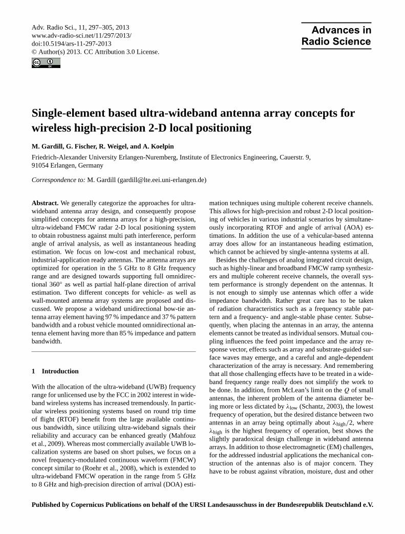
Fig. 2.System architecture of both, RU and MU. Each unit includesfour RX and one TX channel. The RX channel outputs (beat signal)are sampled and handed over to an FPGA implementing the distanceand DOA estimation algorithms.
The distance as well as DOA estimation is based on awideband FMCW radar principle. The FMCW synthesizerof the RU generates a highly-linear frequency ramp in therange from 5 GHz to 8 GHz. This ramp is transmitted usinga single TX channel to the MU. The MU, which has beensynchronized to the RU as described inRoehr et al.(2008)andRoehr(2009), receives the signal from the RU using thefour available RX channels, mixes it down with the locallygenerated FMCW ramp, and outputs the amplified and lowpass filtered mixing product (the beat signal) to an analogto digital converter. Frequency estimation algorithms imple-mented in an FPGA are used to estimate the time of flightbetween both stations based on the beat frequency. Mutualinformation between the four coherent receive channels, e.g.the phase difference, is used to perform spatial signal pro-cessing such as DOA estimation.
2.3 Antenna functional specification
2.3.1 Pattern
The pattern of the antenna array is specified in terms of indi-vidual sensor pattern, since the basic assumption of the signalprocessing algorithms is that the output signals of the fourRX channels are obtained by sampling the impinging wavefront at the position of the RX antennas, using uncoupled in-dividual sensors. This means the pattern of each element forreceiving an impinging wave front is of interest.
The desired receiving element patterns are illustrated inFigure 3. The elevation plane patterns for both the vehicleand wall-mounted antenna arrays should possess a narrowbeam width to suppress parasitic multipath components dueto ceiling and floor reflections. The wall mounted antennaarray sensors need a unidirectional but wide-angle patternavoiding interactions of the array with the mounting struc-tures, e.g. a wall or the supports of a high-level rack, whileenabling wide-angle RU operation and wide-angle DOAestimation. In contrast, each vehicle-mounted array sensor
Fig. 3. Desired receiving element patterns for vehicle- and wall-mounted antenna arrays.(a) view from side showing elevation pat-tern,(b) view from top showing azimuth pattern.
should possess a full omnidirectional azimuth radiation pat-tern to enable 360◦ DOA estimation and ensure proper MUoperation regardless of the vehicle’s heading.
2.3.2 Polarization
Since the z and z’ axes of the global and the MU-local coor-dinate systems are parallel (see Sect. 2.1) a linearly polarizedsystem may be used. Whereas the planar wall mounted struc-ture offers a great flexibility in polarization selection, the factthat the vehicular array will be mounted on the metallic roofof, e.g. the fork lifter, implies a benefit for vertically polar-ized antennas.
2.3.3 Phase center and dispersion
The phase center as well as the dispersive properties of anantenna are important parameters in time-reference radio po-sitioning systems (Best, 2004) and in the particular case ofFMCW systems, frequency dependent phase center move-ment has been reported to create a parasitic Doppler effect(Bares et al., 2003). Phase center displacement effects areclosely related to dispersive effects, which are extensivelytreated by the impulse-based UWB community (Schantz,2003). However, it is generally accepted that those effectsare most pronounced for antennas which rely on frequency-independent design criteria such as spiral and log-periodicantennas, which are indeed optimized to operate over a broadfrequency range, but only for signals having a relatively nar-row instantaneous bandwidth. Dispersive effects are gener-ally less distinct for impulse-radiating UWB antennas suchas conical or wideband dipole or monopole structures.
www.adv-radio-sci.net/11/297/2013/ Adv. Radio Sci., 11, 297–305, 2013
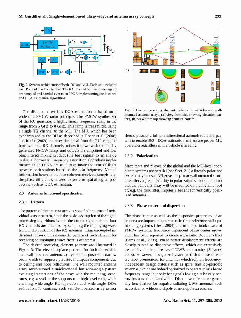
300 M. Gardill et al.: Single-element based ultra-wideband antenna array concepts
Our concept of a wideband FMCW secondary radar sys-tem is somewhere in between an impulse-radiating systemand a system of only narrow instantaneous bandwidth, sincethe FMCW sweep rate determines the transition from nar-row to large instantaneous bandwidth. For practically rele-vant sweep rates the constraints on the time-domain proper-ties of the antennas will never be as strict as in impulse-basedsystems. We thus reduce our attention to antenna elementsbeing reported in the UWB community to have well-behaveddispersive properties, assume that the parasitic dispersive ef-fects can be neglected in our system, and desist from an ex-tensive treatment of dispersive properties in a first approxi-mation. Of course, once working concepts for the antenna ar-rays for wideband FMCW DOA estimation have been found,a complete characterization and evaluation including phasecenter as well as dispersive effects is necessary.
2.4 Ultra-wideband antenna array concepts
Research on UWB antenna arrays can be categorized intotwo tiers: the classical approach which starts by selectingand optimizing an isolated wideband antenna element, thenintegrating the isolated element into an array, and finally ac-counting for mutual coupling and other parasitic effects byre-designing the antenna structure or by using compensa-tion and calibration algorithms in the digital processing do-main (Wang and Hui, 2011; Dandekar et al., 2002; Adve andSarkar, 2000). The major problems in this approach are thefact that the dimensions of a isolated wideband antenna ele-ment are usually in the order ofλlow/2, but the desired ele-ment distanced for grating lobe free operation in the wholeoperating frequency range isd < λhigh/2. In addition mostof the proposed UWB antenna elements are, due to their ge-ometrical construction, not suitable for array integration.
In the last few years a new and promising approach toUWB antenna array design has emerged, which directly uti-lizes the coupling between electrically small elements in aninfinite array to realize ultra-wideband performance and thenaccounts for the truncation of the infinite array in a secondstep (Jones and Rawnick, 2007). Arrays based on the tightlycoupled approaches have been reported to yield extremelywide impedance bandwidths, have a stable radiation pattern,due to the small element size ensure a grating-lobe free op-erating range up to a very high frequency, are suitable forplanar, low-profile implementation, and may also be con-verted to conformal structures (Munk, 2003; Holland, 2011;Lee, 2007). However, since tightly coupled antenna arraysare theoretically based on an infinite periodic structure, theirfinite implementations also rely on a large number of ele-ments (Holland, 2011; Holland and Vouvakis, 2010, 2012)and thus a large amount of transmit/receive (TR) modules orindependent receive channels is necessary. This dramaticallyincreases the cost and is not yet suited for civil commerciallow-cost localization systems. As mentioned in Sect. 2.2, inour particular case the RF frontend is limited to only four
independent receive channels. This is a wide discrepancy be-tween the large number of required elements for a tightlycoupled realization and a great challenge when consideringthe use of tightly-coupled arrays in the proposed localizationsystem.
It is obvious that neither the classical isolated elementbased design method, nor the novel theory of UWB arraysusing tightly-coupled electrically small elements provides anout-of-the-box solution. We generally focus on the examina-tion and study of both concepts, but restrict the focus ontosimplified isolated-element based UWB antenna arrays inthis contribution.
The antenna arrays discussed in this section are based onwideband antenna elements, which in a first step are designedand optimized in isolation, and then incorporated into an an-tenna array. After a preliminary study of the vast amountof UWB antenna elements available in literature, based onthe antenna functional specification from Sect. 2.3 two mostpromising antenna elements have been selected as possiblecandidates. These are the famous Bow Tie antenna elementfor a planar, wall-mounted array, and the monocone antennaelement for the omnidirectional vehicle array. Those basicconcepts have been optimized for the target application needsand novel design modifications are discussed in the followingsection.
2.4.1 The planar wideband reflector backed bow tiewith pattern stabilization
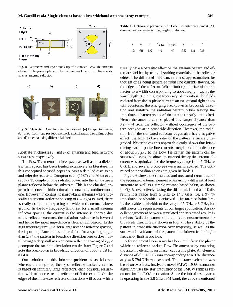
A proposed antenna element for an isolated-element basedwall-mounted antenna array is a Bow Tie antenna printed ona dielectric substrate, above a planar reflector. A mechani-cal robust and low-cost separation of antenna and reflector isachieved by using a readily available PTFE block of thick-nesst . The planar reflector is in turn printed on a seconddielectric substrate and simultaneously acts as ground planefor the feed network printed on the opposing side of the re-flector substrate. This layer stack-up is illustrated in Figure4.The antenna is fed from the back side by using an impedancecontrolled two-wire transmission line, realized by two silverplated copper wires press fitted into precisely drilled holesand penetrating the ground plane reflector through an rect-angular aperture. On both the antenna and the feed networklayer the feed lines are soldered to the antenna and feed net-work metallization, respectively. Whereas an unlimited vari-ety of antenna metallization shapes is available and their ben-efits and drawbacks have been extensively studied in litera-ture, we focus on a rounded-edge Bow Tie antenna (REBA),since this has been reported to yield good return loss results(Qu and Ruan, 2006) and simplifies the design by reduc-ing the antenna metallization degrees of freedom to merelythree: the opening angleα, the Bow Tie radiusr, and the gapwidth w. The entire antenna element has several additionaldegrees of freedom which are the PTFE thicknesst , the twinwire feed line diameterd and conductor separations, and the
Adv. Radio Sci., 11, 297–305, 2013 www.adv-radio-sci.net/11/297/2013/
M. Gardill et al.: Single-element based ultra-wideband antenna array concepts 301
Fig. 4. Geometry and layer stack up of proposed Bow Tie antennaelement. The groundplane of the feed network layer simultaneouslyacts as antenna reflector.
Fig. 5. Fabricated Bow Tie antenna element.(a) Perspective view,(b) view from top,(c) feed network metallization including balunand d) antenna using differential feed.
substrate thicknessest1 and t2 of antenna and feed networksubstrates, respectively.
The Bow Tie antenna in free space, as well as on a dielec-tric half space, has been treated extensively in literature. Inthis conceptual-focused paper we omit a detailed discussionand refer the reader toCompton et al.(1987) andAllen et al.(2007). To couple out the radiated power into the air we use aplanar reflector below the substrate. This is the classical ap-proach to convert a bidirectional antenna into a unidirectionalone. However, in contrast to narrowband antennas where typ-ically an antenna-reflector spacing oft = λd/4 is used, thereis really no optimum spacing for wideband antennas aboveground: In the low frequency limit, i.e. for a small antennareflector spacing, the current in the antenna is shorted dueto the reflector currents, the radiation resistance is loweredand hence the input impedance is strongly influenced. In thehigh frequency limit, i.e. for a large antenna reflector spacing,the input impedance is less altered, but for a spacing largerthanλd/4 the pattern in broadside direction breaks down un-til having a deep null at an antenna reflector spacing ofλd/2, compare the far field simulation results from Figure 7 andnote the breakdown in broadside direction of about 6 dB for8 GHz.
Our solution to this inherent problem is as follows:whereas the simplified theory of reflector backed antennasis based on infinitely large reflectors, each physical realiza-tion will, of course, use a reflector of finite extend. On theedges of the finite-size reflector diffractions will occur, which
Table 1. Optimized parameters of Bow Tie antenna element. Alldimensions are given in mm, angles in degree.
r α w hsubs wsubs t s d
12 68 1.6 40 40 8.5 1.8 0.8
usually have a parasitic effect on the antenna pattern and of-ten are tackled by using absorbing materials at the reflectoredges. The diffracted field can, in a first approximation, bethought of as being generated from line currents flowing onthe edges of the reflector. When limiting the size of the re-flector to a width corresponding to aboutwsubs= λhigh, thewavelength at the highest frequency of operation, the fieldsradiated from the in-phase currents on the left and right edgeswill counteract the emerging breakdown in broadside direc-tion and stabilize the radiation pattern, while leaving theimpedance characteristics of the antenna nearly untouched.Hence the antenna can be placed at a larger distance thanλd,high/4 from the reflector, without occurrence of the pat-tern breakdown in broadside direction. However, the radia-tion from the truncated reflector edges also has a negativeeffect: the front to back ratio of the pattern is severely de-graded. Nevertheless this approach clearly shows that intro-ducing two in-phase line currents, neighbored at a distanceof aboutλhigh/2 to the Bow Tie center, the pattern can bestabilized. Using the above mentioned theory the antenna el-ement was optimized for the frequency range from 5 GHz to8 GHz and several prototypes were manufactured. The opti-mized antenna dimensions are given in Table 1.
Figure6 shows the simulated and measured return loss ofthe optimized antenna element when using a differential feedstructure as well as a simple rat-race based balun, as shownin Fig. 5, respectively. Using the differential feed a−10 dBreturn loss range from 5 GHz to 14.5 GHz, i.e. a 97 %impedance bandwidth, is achieved. The rat-race balun lim-its the usable bandwidth to the range of 5 GHz to 8 GHz, butstill meets the requirements of our target application. An ex-cellent agreement between simulated and measured results isobvious. Radiation pattern simulations and measurements forbroadside direction are shown in Fig.7. The stability of thepattern in broadside direction over frequency, as well as thesuccessful avoidance of the pattern breakdown in the high-frequency limit is obvious.
A four-element linear array has been built from the planarwideband reflector backed Bow Tie antennas by mountingthe antenna elements on a laser-cut acrylic plate. An elementdistance ofd = 46.567 mm corresponding to a 0.9λ distanceat f = 5.794 GHz was selected. The distance selection wasbased on two facts: firstly, the novel FMWC DOA estimationalgorithm uses the start frequency of the FMCW ramp as ref-erence for the DOA estimation. Since the initial test systemis operating in the 5.8 GHz ISM band, the above mentioned
www.adv-radio-sci.net/11/297/2013/ Adv. Radio Sci., 11, 297–305, 2013

302 M. Gardill et al.: Single-element based ultra-wideband antenna array concepts
0 5 10 15 20−40
−20
0
meas. balunsim. balunmeas. diff.sim. diff.
S11in
[dB]
f in [GHz]
Fig. 6.Measured return loss of proposed Bow Tie antenna.−10 dBreturn loss range using differential feed is from 5 GHz to 14.5 GHz,i.e. 97 % bandwidth. Rat-race limits useable bandwidth from 5 GHzto 8 GHz.
−50 0 50−20
−10
0
5 GHz6 GHz7 GHz8 GHz
Patternin
[dB]
θ in [deg]
−50 0 50−20
−10
0
Patternin
[dB]
θ in [deg]
−50 0 50−20
−10
0
Patternin
[dB]
θ in [deg]
Fig. 7. Simulated and measured H-plane patterns of proposed BowTie antenna. (top) Simulation on infinite ground plane showing pat-tern breakdown at high-frequency limit, (center) simulation resultson truncated reflector showing breakdown compensation, and (bot-tom) measurements of proposed element proving breakdown com-pensation.
reference frequency results. Secondly, the desired range ofambiguity-free DOA estimation has been lowered to a rangeof 45◦ from broadside direction. This allows to use the rela-tively large elements with an element spacing up toλ. A pho-tograph of the prototype array is included as inset in Fig.8and the simulated 4-port S-parameter results are given in theplot of Fig.8. The simulation results show a good impedancematch in the desired operating frequency range from 5 GHz
3 4 5 6 7 8 9 10
−50−40−30−20−10
S11in
[dB]
f in [GHz]
Fig. 8. Simulated four-port S-Parameters of Bow Tie antenna arrayusing differential feed. Return loss is marginally altered, transmitmode coupling is below−20 dB.
to 8 GHz and an acceptable transmit mode coupling of max-imum −20 dB to neighbored elements. A full measurementcharacterization of the prototype array in receive mode is on-going.
In conclusion, the Bow Tie based antenna array conceptmay be suitable if the desired ambiguity-free DOA estima-tion range can be limited to±45◦ from broadside direction,since the widthwsubsof the wideband elements is in the orderof a wavelength at the lowest frequency of operation. Whilenot inherently offering a narrow elevation pattern, this can beachieved by connecting several vertically stacked Bow Tieelements in phase. Still some work has to be done on inte-grating the antenna elements onto a common substrate andabove a common large reflector. In particular this means thatthe pattern stabilization mechanism, which is based on thereflector truncation, has either to be omitted, or implementedby means of another stabilization method.
2.4.2 The monocone above ground
The theory of Bow Tie antennas and monocone antennas es-sentially has the same origin and their electromagnetic be-havior is comparable to a great extent. Monocone structuresabove ground planes can be derived from biconical structuresusing image theory, which have been extensively treated bySchelkunoff(1951). Planar Bow Tie structures in turn canbe analytically treated by deriving their characteristic modesin a sphero-conal coordinate system degraded to its planarequivalent (Stockbroeckx and Vander Vorst, 2000). Henceboth antenna types are based on the same radiation mecha-nism, which idealizes them for a paired used in the proposedFMCW localization system. Again we skip a detailed treat-ment of monocone structures in this paper, refer the inter-ested reader to the provided literature, and discuss the con-ceptual benefits and the optimized antenna element in thissection.
Although monoconical structures are one of the oldest an-tenna elements – the first one was already used by Marconiat the radio station in Poldhu, Cornwall (Simons, 1996) –they still are subject to current research and due to theirwide bandwidth became a quasi-reference in UWB antenna
Adv. Radio Sci., 11, 297–305, 2013 www.adv-radio-sci.net/11/297/2013/

M. Gardill et al.: Single-element based ultra-wideband antenna array concepts 303
Fig. 9. Technical drawings of proposed monocone antennas Type1(left), Type2 (center), and exploded view of Type 1 (right).
designs. Recent publications are often dealing with improv-ing the electromagnetic characteristics (Aten and Haupt,2009; Taniguchi and Kobayashi, 2003; Hu et al., 2011), butan important fact which often is neglected is the design ofpractically relevant antenna structures which cover both, de-sired electromagnetic radiation characteristics as well as a ro-bust mechanical construction protecting the antenna from en-vironmental influence such as dust, moisture, vibrations andother mechanical influences, and enabling it to be mountedon various objects. Since every additional structure intro-duced into the area surrounding an antenna changes its elec-tromagnetic behavior, the aforementioned practically rele-vant characteristics are not simply a problem of mechanicaldesign, but detailed and in-depth treatment of electromag-netic and mechanical characteristics is necessary.
For the development of a simplified isolated-antenna el-ement based vehicle mounted antenna array, we concen-trate our research onto the development of a practicallyrelevant monocone antenna, which can easily be manufac-tured, mounted, and offers the necessary mechanical stabil-ity. A technical drawing of the proposed monocone antennais given in Fig.9. The basic construction of the proposedmonocone antenna, referred to as Type 1, is illustrated inFig. 9. The key concept of the antenna is a metallic conicalstructure of heighthconewhich has two cylindrical extensionson the top and the bottom, with heightshcyl andhcoax, respec-tively. The upper cylindrical extension is used for impedancetuning and serves as a fixture against lateral movements ina second version of the monocone antenna, referred to astype 2 (Fig.9). The lower cylindrical extension is insertedinto a hole drilled in the antenna socket. The socket acts asthe ground plane, or counterpoise system, and as a fixturefor the antenna module. To fix the cone in the right positionabove the socket two PTFE parts are used. The inner PTFEpart has an exact imprint of the cone, such that the cone canbe pressed into it and is securely fixed. The lower cylindricalextension of the inner PTFE part is then tightly pressed intothe hole drilled into the socket and thus precisely aligns theaxes of the cone lower cylindrical extension, inner PTFE part
0 5 10 15 20−30
−20
−10
0
S11in
[dB]
f in [GHz]
Fig. 10.Simulated (dashed lines) and measured (solid lines) returnloss results for antenna Type 1 (green) and antenna Type 2 (blue).
cylindrical extension, and the hole drilled in the socket. Thelower parts form a coaxial structure which is used to feedthe antenna element. To protect the antenna structure fromenvironmental influences the outer PTFE cylinder is used. Aholed drilled in the cylinder exactly matches the outer diam-eter of the inner PTFE part and when putting over the outerPTFE part over the combination of inner PTFE and cone,a tightened unit is created. This unit is then inserted into thesocket, compare the explosion drawing from Fig.9. The con-struction is inherently self-fixed against lateral movements,but a vertical fixture of all parts has to be ensured. This isrealized by means of nylon threaded rods, which are screwedinto four threads in the outer PTFE cylinder, which penetratethe socket through four drills, and which are then locked onthe bottom side of the socket with nylon nuts. This methodof fixing the antenna structure increases the antenna dimen-sions, since minimum necessary material thicknesses for thescrews, the drills, and the threads have to be taken care of. Inaddition the nylon screws introduce an inhomogeneity intothe dielectric near the cone apex disturbing the outward prop-agating spherical waves and thus have a negative influence onthe antenna characteristics.
Hence, the monocone Type 2 was developed. Whereas itis generally based on the same construction principles, it en-sures the vertical stability of all components using adhesiveconnections which can be realized by pretreatment of thePTFE surfaces with a reactive process gas or an n-Heptanebased liquid primer. Without the need for nylon bolts the an-tenna can be reduced in size and its characteristics can beoptimized. In addition the adhesive serves as seal betweenthe antenna parts and realizes an effective protection againstmoisture and dust.
From the bottom of the socket a flange-mount SMA con-nector with extended PTFE dielectric and extended innerconductor is used to interface the antenna. As can be seenfrom the technical drawings, the dielectric from the connec-tor and antenna are pressed against each other, where thelow flexural strength of PTFE ensures a tight connection.In contrast it can be seen that a small gap of heighthsprbetween the center conductors of the coaxial constructionexist. This gap is filled with golden a spring-like mesh (aFuzzButton), which is tightly pressed against the conductors
www.adv-radio-sci.net/11/297/2013/ Adv. Radio Sci., 11, 297–305, 2013
304 M. Gardill et al.: Single-element based ultra-wideband antenna array concepts
Table 2. Optimized geometry of monocone antennas Type 1 andType 2. All dimensions are in millimeters.
hgnd hcone hcyl hcoax w1 w2 dtop ddiel
1 8.1 2 2.2 1.25 8.67 21 4.11 8.1 2 2.2 1.25 8.67 16 4.1
0 30 60 90 120 150 180
−30
−20
−10
0
Patternin
[dB]
θ in [deg]
0 50 100 150−40
−20
0
Patternin
[dB]
θ in [deg]
1087654freq. in GHz:
Fig. 11.Measured Co-polar and X-polar elevation pattern of Type 1(top) and Type 2 (bottom) antennas, respectively. Groundplane sizedplate= 300mm.
of SMA connector and cone and thus ensures a reliable coax-ial connection avoiding any imperfections in the feed lineimpedance.
Starting from rough estimates on the necessary dimensionsof the conical structure obtained from theory and previousexaminations on biconical structures, we numerically opti-mized the antenna geometry in the frequency range from5 GHz to 8 GHz using a commercially available electromag-netics software package. The optimized values are given inTable 2.
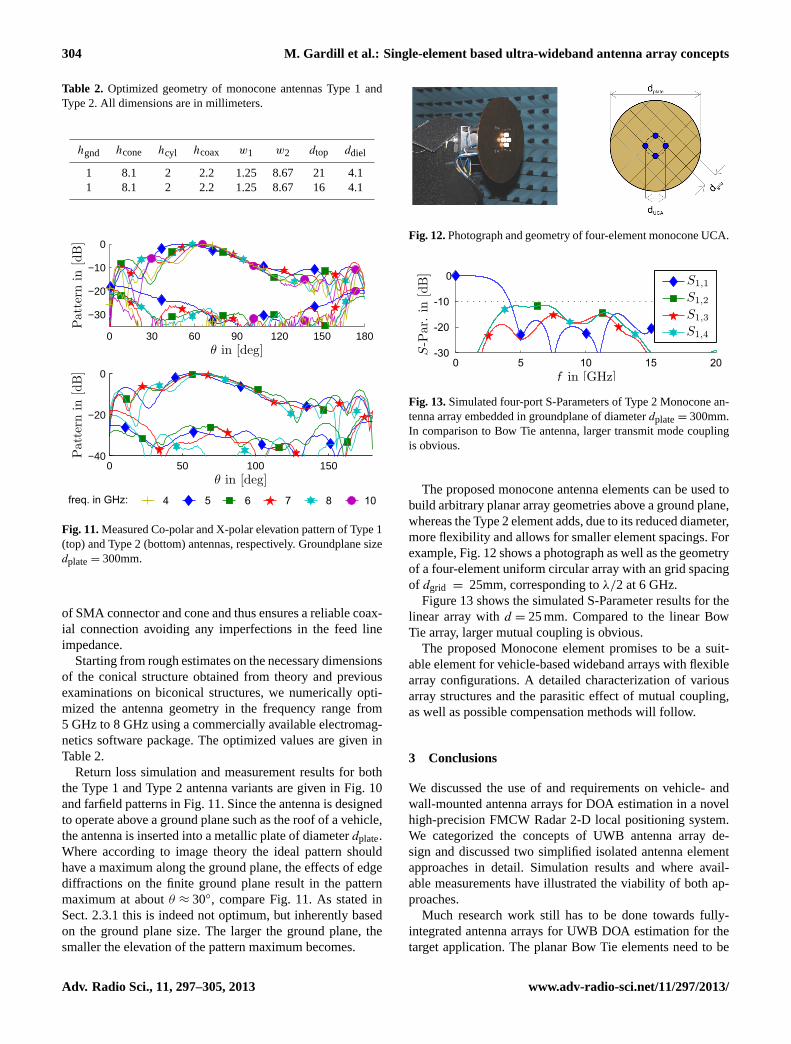
Return loss simulation and measurement results for boththe Type 1 and Type 2 antenna variants are given in Fig.10and farfield patterns in Fig.11. Since the antenna is designedto operate above a ground plane such as the roof of a vehicle,the antenna is inserted into a metallic plate of diameterdplate.Where according to image theory the ideal pattern shouldhave a maximum along the ground plane, the effects of edgediffractions on the finite ground plane result in the patternmaximum at aboutθ ≈ 30◦, compare Fig.11. As stated inSect. 2.3.1 this is indeed not optimum, but inherently basedon the ground plane size. The larger the ground plane, thesmaller the elevation of the pattern maximum becomes.
Fig. 12.Photograph and geometry of four-element monocone UCA.
0 5 10 15 20
-30
-20
-10
0
S-Par.
in[dB]
f in [GHz]
S1,1
S1,2
S1,3
S1,4
Fig. 13.Simulated four-port S-Parameters of Type 2 Monocone an-tenna array embedded in groundplane of diameterdplate= 300mm.In comparison to Bow Tie antenna, larger transmit mode couplingis obvious.
The proposed monocone antenna elements can be used tobuild arbitrary planar array geometries above a ground plane,whereas the Type 2 element adds, due to its reduced diameter,more flexibility and allows for smaller element spacings. Forexample, Fig.12shows a photograph as well as the geometryof a four-element uniform circular array with an grid spacingof dgrid = 25mm, corresponding toλ/2 at 6 GHz.
Figure13 shows the simulated S-Parameter results for thelinear array withd = 25 mm. Compared to the linear BowTie array, larger mutual coupling is obvious.
The proposed Monocone element promises to be a suit-able element for vehicle-based wideband arrays with flexiblearray configurations. A detailed characterization of variousarray structures and the parasitic effect of mutual coupling,as well as possible compensation methods will follow.
3 Conclusions
We discussed the use of and requirements on vehicle- andwall-mounted antenna arrays for DOA estimation in a novelhigh-precision FMCW Radar 2-D local positioning system.We categorized the concepts of UWB antenna array de-sign and discussed two simplified isolated antenna elementapproaches in detail. Simulation results and where avail-able measurements have illustrated the viability of both ap-proaches.
Much research work still has to be done towards fully-integrated antenna arrays for UWB DOA estimation for thetarget application. The planar Bow Tie elements need to be
Adv. Radio Sci., 11, 297–305, 2013 www.adv-radio-sci.net/11/297/2013/

M. Gardill et al.: Single-element based ultra-wideband antenna array concepts 305
integrated on a common substrate and therefore the methodfor pattern stabilization has to be improved. The proposedmonocone antennas are a useful and practical antenna design,but a further improvement of their elevation-plane radiationpattern is desirable.
Acknowledgements.This research project is funded by the Bavar-ian Ministry of Economic Affairs, Infrastructure, Transport andTechnology, project. No. IUK-0908-0004 and the European Re-gional Development Fund (ERDF).
References
Adve, R. S. and Sarkar, T. K.: Compensation for the effects of mu-tual coupling on direct data domain adaptive algorithms, IEEE T.Antenn. Propag., 48, 86–94, 2000.
Allen, B., Dohler, M., Okon, E., Malik, W., Brown, A., and Ed-wards, D.: Ultra-wideband: Antennas and Propagation for Com-munications, Radar and Imaging, Wiley, Chichester, West Sus-sex, England, 2007.
Aten, D. and Haupt, R.: Genetically optimized, low profile, wide-band, shorted monocone antenna, in: Antennas and PropagationSociety International Symposium, 2009. APSURSI ’09. IEEE,1–4, doi:10.1109/APS.2009.5171992, 2009.
Bares, C., Brousseau, C., Le Coq, L., and Bourdillon, A.: Ef-fect of antenna phase center displacement on FM-CW measure-ments & application to radar system, in: Antennas and Propaga-tion Society International Symposium, 2003, IEEE, 3, 812–815,doi:10.1109/APS.2003.1220034, 2003.
Best, S.: Distance-measurement error associated with antennaphase-center displacement in time-reference radio positioningsystems, Antennas and Propagation Magazine, IEEE, 46, 13–22,doi:10.1109/MAP.2004.1305530, 2004.
Compton, R., McPhedran, R., Popovic, Z., Rebeiz, G., Tong, P.,and Rutledge, D.: Bow-tie antennas on a dielectric half-space:Theory and experiment, IEEE T. Antenn. Propag., 35, 622–631,doi:10.1109/TAP.1987.1144162, 1987.
Dandekar, K. R., Ling, H., and Xu, G.: Experimentalstudy of mutual coupling compensation in smart an-tenna applications, IEEE T. Wirel. Commun., 1, 480–487,doi:10.1109/TWC.2002.800546, 2002.
Gulden, P., Roehr, S., and Christmann, M.: An overview of wirelesslocal positioning system configurations, in: Proc. IEEE MTT-S Int. Microwave Workshop Wireless Sensing, Local Position-ing, and RFID IMWS, 1–4, doi:10.1109/IMWS2.2009.5307894,2009.
Holland, S. and Vouvakis, M.: A 7-21 GHz Planar Ultra-wideband Modular Array, in: Antennas and PropagationSociety International Symposium (APSURSI), IEEE, 1–4,doi:10.1109/APS.2010.5561424, 2010.
Holland, S. and Vouvakis, M.: The Planar Ultrawideband ModularAntenna (PUMA) Array, IEEE T. Antenn. Propag., 60, 130–140,doi:10.1109/TAP.2011.2167916, 2012.
Holland, S. S.: Low-profile, Modular, Ultra-Wideband Phased Ar-rays, Paper 450, Open Access Dissertations, 2011.
Hu, Z. H., Hall, P. S., Kelly, J. R., and Gardner, P.: Widebandomni conical monopole antenna with high Q band-notched be-haviour, in: Proc. Int Antenna Technology (iWAT) Workshop,37–40, 2011.
Jones, M. and Rawnick, J.: A New Approach to BroadbandArray Design using Tightly Coupled Elements, in: MilitaryCommunications Conference, 2007. MILCOM, IEEE, 1 –7,doi:10.1109/MILCOM.2007.4454764, 2007.
Lee, J. J.: Ultra Wideband Arrays, in: Antenna Engineering Hand-book, edited by Volakis, J. L., chap. 24, 1–24, Mcgraw-Hill Pro-fessional, New York, NY, USA, 2007.
Mahfouz, M. R., Fathy, A. E., Kuhn, M. J., and Wang, Y.: Recenttrends and advances in UWB positioning, in: Proc. IEEE MTT-SInt. Microwave Workshop Wireless Sensing, Local Positioning,and RFID IMWS, 1–4, 2009.
Munk, B.: Finite Antenna Arrays and FSS, Wiley, 2003.Qu, B. S.-W. and Ruan, C.-L.: Effect of round corners on bowtie
antennas, Progress In Electromagnetics Research, 57, 179–195,2006.
Roehr, S.: System-Theoretic Analysis and Optimization of a NovelSecondary Radar Concept for Precise Distance and VelocityMeasurement, Logos Verlag Berlin, 2009.
Roehr, S., Gulden, P., and Vossiek, M.: Precise Distance and Ve-locity Measurement for Real Time Locating in Multipath Envi-ronments Using a Frequency-Modulated Continuous-Wave Sec-ondary Radar Approach, IEEE T. Microw. Theor., 56, 2329–2339, doi:10.1109/TMTT.2008.2003137, 2008.
Schantz, H. G.: Introduction to ultra-wideband antennas, in: Proc.IEEE Conf. Ultra Wideband Systems and Technologies, 1–9,doi:10.1109/UWBST.2003.1267792, 2003.
Schelkunoff, S. A.: Electromagnetic waves, The Bell TelephoneLaboratories series., Van Nostrand, Toronto (u.a.), 7. print. edn.,the Bell Telephone Laboratories series, 1951.
Simons, R. W.: Guglielmo Marconi and Early Systems of WirelessCommunication, General Electric Company Review, 11, 37–55,1996.
Stockbroeckx, B. and Vander Vorst, A.: Electromagnetic modesin conical transmission lines with application to the linearlytapered slot antenna, IEEE T. Antenn. Propag., 48, 447–455,doi:10.1109/8.841906, 2000.
Taniguchi, T. and Kobayashi, T.: An omnidirectional and low-VSWR antenna for the FCC-approved UWB frequency band, in:IEEE Antenn. Propag., 3, 460–463, 2003.
Wang, B. H. and Hui, H. T.: Wideband mutual coupling compensa-tion for receiving antenna arrays using the system identificationmethod, IET Microw. Antenna. P., 5, 184–191, doi:10.1049/iet-map.2010.0120, 2011.
www.adv-radio-sci.net/11/297/2013/ Adv. Radio Sci., 11, 297–305, 2013

![Affordable Wideband Multifunction Phased Array Antenna ...significant interest to develop multi-function arrays using a single wideband antenna [1]. However, the number of radiating](https://static.fdocuments.us/doc/165x107/5e84599e1c130a3f7c126a53/affordable-wideband-multifunction-phased-array-antenna-significant-interest.jpg)