Single Direction Plates - Wacker...
44
www.wackergroup.com Single Direction Plates VP 1340A/AW VP 1550A/AW VP 1340R/RW VP 1550R/RW VP 1135A/AW VP 1135R/RW VP 2050A VP 2050R VP 2050Y REPAIR MANUAL 0157472en 001 0204 0 1 5 7 4 7 2 E N
Transcript of Single Direction Plates - Wacker...
www.wackergroup.com
Single Direction Plates
VP 1340A/AWVP 1550A/AWVP 1340R/RWVP 1550R/RWVP 1135A/AWVP 1135R/RWVP 2050AVP 2050RVP 2050Y
REPAIR MANUAL
0157472en 001
0204
0 1 5 7 4 7 2 E N


VP Repair Table of Contents
1. Foreword 3
2. Safety Information 4
2.1 Laws Pertaining to Spark Arresters ...................................................... 42.2 Operating Safety .................................................................................. 52.3 Operator Safety while using Internal Combustion Engines .................. 62.4 Service Safety ...................................................................................... 7
3. Technical Data 8
3.1 VP 1340A/AW, VP 1550A/AW ............................................................. 83.2 VP 1340R/RW, VP 1550R/RW ........................................................... 103.3 VP 1135A/AW .................................................................................... 123.4 VP 1135R/RW .................................................................................... 133.5 VP 2050A ........................................................................................... 153.6 VP 2050R ........................................................................................... 163.7 VP 2050Y ........................................................................................... 18
4. General 21
4.1 Application .......................................................................................... 214.2 Periodic Maintenance Schedule ......................................................... 22
5. Baseplate 23
5.1 Exploded View - VP ............................................................................ 235.2 Guide Handle - VP ............................................................................. 265.3 Drive Belt ............................................................................................ 275.4 Engine ................................................................................................ 29
6. Exciter 30
6.1 Exciter Exploded View ...................................................................... 306.2 Exciter ................................................................................................ 31
wc_br0157472001enTOC.fm 1

Table of Contents VP Repair
7. Clutch 32
7.1 Clutch ..................................................................................................327.2 Clutch Engagement Speed Test .........................................................33
8. Water System 34
8.1 Water System Exploded View - VP .....................................................34
9. Troubleshooting 36
wc_br0157472001enTOC.fm 2
wc_tx000001gb.fm 3
CALIFORNIA
Proposition 65 Warning:
Engine exhaust, some of its constituents, and certain vehiclecomponents contain or emit chemicals known to the State of Californiato cause cancer and birth defects or other reproductive harm.
1. Foreword
This manual provides information and procedures to safely operateand maintain this Wacker model. For your own safety and protectionfrom injury, carefully read, understand and observe the safetyinstructions described in this manual.
Keep this manual or a copy of it with the machine. If you lose thismanual or need an additional copy, please contact WackerCorporation. This machine is built with user safety in mind; however,it can present hazards if improperly operated and serviced. Followoperating instructions carefully! If you have questions about operatingor servicing this equipment, please contact Wacker Corporation.
The information contained in this manual was based on machines inproduction at the time of publication. Wacker Corporation reserves theright to change any portion of this information without notice.
All rights, especially copying and distribution rights, are reserved.
Copyright 2004 by Wacker Corporation.
No part of this publication may be reproduced in any form or by anymeans, electronic or mechanical, including photocopying, withoutexpress written permission from Wacker Corporation.
Any type of reproduction or distribution not authorized by WackerCorporation represents an infringement of valid copyrights and will beprosecuted. We expressly reserve the right to make technicalmodifications, even without due notice, which aim at improving ourmachines or their safety standards.
WARNING

Safety Information VP Repair
2. Safety Information
This manual contains DANGER, WARNING, CAUTION, and NOTEcallouts which must be followed to reduce the possibility of personalinjury, damage to the equipment, or improper service.
This is the safety alert symbol. It is used to alert you to potentialpersonal injury hazards. Obey all safety messages that follow thissymbol to avoid possible injury or death.
DANGER indicates an imminently hazardous situation which, if notavoided, will result in death or serious injury.
WARNING indicates a potentially hazardous situation which, if notavoided, could result in death or serious injury.
CAUTION indicates a potentially hazardous situation which, if notavoided, may result in minor or moderate injury.
CAUTION: Used without the safety alert symbol, CAUTION indicatesa potentially hazardous situation which, if not avoided, may result inproperty damage.
Note: Contains additional information important to a procedure.
2.1 Laws Pertaining to Spark Arresters
Notice: State Health Safety Codes and Public Resources Codesspecify that in certain locations spark arresters be used on internalcombustion engines that use hydrocarbon fuels. A spark arrester is adevice designed to prevent accidental discharge of sparks or flamesfrom the engine exhaust. Spark arresters are qualified and rated bythe United States Forest Service for this purpose.
In order to comply with local laws regarding spark arresters, consultthe engine distributor or the local Health and Safety Administrator.
DANGER
WARNING
CAUTION
wc_si000109gb.fm 4

VP Repair Safety Information
2.2 Operating Safety
Familiarity and proper training are required for the safe operation ofequipment! Equipment operated improperly or by untrained personnelcan be dangerous! Read the operating instructions contained in boththis manual and the engine manual and familiarize yourself with thelocation and proper use of all controls. Inexperienced operators shouldreceive instruction from someone familiar with the equipment beforebeing allowed to operate the machine.
2.2.1 NEVER allow anyone to operate this equipment without propertraining. People operating this equipment must be familiar with therisks and hazards associated with it.
2.2.2 NEVER touch the engine or muffler while the engine is on orimmediately after it has been turned off. These areas get hot and maycause burns.
2.2.3 NEVER use accessories or attachments that are not recommended byWacker. Damage to equipment and injury to the user may result.
2.2.4 NEVER operate the machine with the belt guard missing. Exposeddrive belt and pulleys create potentially dangerous hazards that cancause serious injuries.
2.2.5 NEVER leave machine running unattended.
2.2.6 ALWAYS be sure operator is familiar with proper safety precautionsand operation techniques before using machine.
2.2.7 ALWAYS wear protective clothing appropriate to the job site whenoperating equipment.
2.2.8 ALWAYS wear hearing protection when operating equipment.
2.2.9 ALWAYS close fuel valve on engines equipped with one whenmachine is not being operated.
2.2.10 ALWAYS store equipment properly when it is not being used.Equipment should be stored in a clean, dry location out of the reach ofchildren.
2.2.11 ALWAYS operate machine with all safety devices and guards in placeand in working order. DO NOT modify or defeat safety devices. DONOT operate machine if any safety devices or guards are missing orinoperative.
2.2.12 ALWAYS read, understand, and follow procedures in Operator’sManual before attempting to operate equipment.
WARNING
wc_si000109gb.fm 5

Safety Information VP Repair
2.3 Operator Safety while using Internal Combustion Engines
Internal combustion engines present special hazards during operationand fueling! Read and follow warning instructions in engine owner’smanual and safety guidelines below. Failure to follow warnings andsafety guidelines could result in severe injury or death.
2.3.1 DO NOT run machine indoors or in an enclosed area such as a deeptrench unless adequate ventilation, through such items as exhaustfans or hoses, is provided. Exhaust gas from the engine containspoisonous carbon monoxide gas; exposure to carbon monoxide cancause loss of consciousness and may lead to death.
2.3.2 DO NOT smoke while operating machine.
2.3.3 DO NOT smoke when refueling engine.
2.3.4 DO NOT refuel hot or running engine.
2.3.5 DO NOT refuel engine near open flame.
2.3.6 DO NOT spill fuel when refueling engine.
2.3.7 DO NOT run engine near open flames.
2.3.8 ALWAYS refill fuel tank in well-ventilated area.
2.3.9 ALWAYS replace fuel tank cap after refueling.
2.3.10 ALWAYS check fuel lines and fuel tank for leaks and cracks beforestarting engine. Do not run machine if fuel leaks are present or fuellines are loose.
DANGER
wc_si000109gb.fm 6
VP Repair Safety Information
2.4 Service Safety
Poorly maintained equipment can become a safety hazard! In orderfor the equipment to operate safely and properly over a long period oftime, periodic maintenance and occasional repairs are necessary.
2.4.1 DO NOT attempt to clean or service machine while it is running.Rotating parts can cause severe injury.
2.4.2 DO NOT crank a flooded engine with the spark plug removed ongasoline-powered engines. Fuel trapped in the cylinder will squirt outthe spark plug opening.
2.4.3 DO NOT test for spark on gasoline-powered engines, if engine isflooded or the smell of gasoline is present. A stray spark could ignitefumes.
2.4.4 DO NOT use gasoline or other types of fuels or flammable solvents toclean parts, especially in enclosed areas. Fumes from fuels andsolvents can become explosive.
2.4.5 ALWAYS keep area around muffler free of debris such as leaves,paper, cartons, etc. A hot muffler could ignite them, starting a fire.
2.4.6 ALWAYS replace worn or damaged components with spare partsdesigned and recommended by Wacker.
2.4.7 ALWAYS disconnect spark plug on machines equipped with gasolineengines, before servicing, to avoid accidental start-up.
2.4.8 ALWAYS keep machine clean and labels legible. Replace all missingand hard-to-read labels. Labels provide important operatinginstructions and warn of dangers and hazards.
WARNING
wc_si000109gb.fm 7
Technical Data VP Repair
3. Technical Data
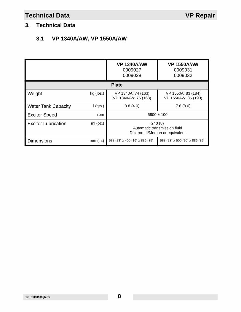
3.1 VP 1340A/AW, VP 1550A/AW
VP 1340A/AW00090270009028
VP 1550A/AW00090310009032
Plate
Weight kg (lbs.) VP 1340A: 74 (163)VP 1340AW: 76 (168)
VP 1550A: 83 (184)VP 1550AW: 86 (190)
Water Tank Capacity l (qts.) 3.8 (4.0) 7.6 (8.0)
Exciter Speed rpm 5800 ± 100
Exciter Lubrication ml (oz.) 240 (8)Automatic transmission fluid
Dextron III/Mercon or equivalent
Dimensions mm (in.) 588 (23) x 400 (16) x 886 (35) 588 (23) x 500 (20) x 886 (35)
wc_td000108gb.fm 8

VP Repair Technical Data
VP 1340A/AW00090270009028
VP 1550A/AW00090310009032
Engine
Engine Make Honda
Engine Model GX 160 K1 QX2
Rated Power kW (Hp) 4.1 (5.5)
Spark Plug NGK BPR 6ES
Electrode Gap mm (in.) 0.7-0.8 (0.028–0.031)
Engine Speed - full load rpm 3600 ± 100
Engine Speed - idle rpm 1600 ± 100
Air Cleaner type Dual element
Engine Lubrication oil grade SAE 10W30SG or SF
Engine Oil Capacity ml (oz.) 600 (20)
Fuel type Regular unleaded gasoline
Fuel Tank Capacity l (qts.) 3.7 (3.9)
Valve Clearance (cold)Inlet:Outlet:
mm (in.) 0.15 (0.006)0.20 (0.008)
wc_td000108gb.fm 9

Technical Data VP Repair
3.2 VP 1340R/RW, VP 1550R/RW
VP 1340R/RW00090290009030
VP 1550R/RW00090330009034
Plate
Weight kg (lbs.) VP 1340R: 74 (163)VP 1340RW: 76 (168)
VP 1550R: 84 (185)VP 1550RW: 87 (191)
Water Tank Capacity l (qts.) 3.8 (4.0) 7.6 (8.0)
Exciter Speed rpm 5800 ± 100
Exciter Lubrication ml (oz.) 240 (8)Automatic transmission fluid
Dextron III/Mercon or equivalent
Dimensions mm (in.) 588 (23) x 400 (16) x 886 (35) 588 (23) x 500 (20) x 886 (35)
wc_td000108gb.fm 10

VP Repair Technical Data
VP 1340R/RW00090290009030
VP 1550R/RW00090330009034
Engine
Engine Make Robin
Engine Model EY20OYD4540
Rated Power kW (Hp) 3.7 (5.0)
Spark Plug NGK BR6HS or Champion RL86C
Electrode Gap mm (in.) 0.6-0.7 (0.020-0.030)
Engine Speed - full load rpm 3600 ± 100
Engine Speed - idle rpm 1600 ± 100
Air Cleaner type Replaceable dry type, paper element with foam precleaner
Engine Lubrication oil gradeservice
class
Above 40° F (4° C) use SAE 30Between 15° F (-9° C) and 40° F (4° C) SAE 20
Below 15° F (-9° C) SAE 10W30SF or SE
Engine Oil Capacity ml (oz.) 600 (20)
Fuel type Regular leaded or unleaded gasoline
Fuel Tank Capacity l (qts.) 3.8 (4.0)
Valve Clearance (cold)Inlet:Outlet:
mm (in.) 0.1 (0.004)0.1 (0.004)
wc_td000108gb.fm 11

Technical Data VP Repair
3.3 VP 1135A/AW
VP 1135A0009057
VP 1135AW0009058
Plate
Weight kg (lbs.) 62 (137) 65 (143)
Water Tank Capacity l (qts.) 3.8 (4)
Exciter Speed rpm 5800 ± 100
Exciter Lubrication ml (oz.) 207 (7)Automatic transmission fluid
Dextron III/Mercon or equivalent
Dimensions mm (in.) 521 (21) x 350 (14) x 884 (35)
VP 1135A0009057
VP 1135AW0009058
Engine
Engine Make Honda
Engine Model GX 120 K1 QX
Rated Power kW (Hp) 3.0 (4.0)
Spark Plug NGK BPR 6ESBOSCH WR 7DC
Electrode Gap mm (in.) 0.7-0.8 (0.028–0.031)
Engine Speed rpm 3600 ± 100
Air Cleaner type Dual element
Engine Lubrication oil grade SAE 10W30SG or SF
Engine Oil Capacity ml (oz.) 600 (20)
Fuel type Regular unleaded gasoline
Fuel Tank Capacity l (qts.) 2.5 (2.6)
wc_td000108gb.fm 12
VP Repair Technical Data
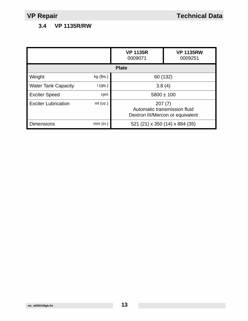
3.4 VP 1135R/RW
VP 1135R0009071
VP 1135RW0009251
Plate
Weight kg (lbs.) 60 (132)
Water Tank Capacity l (qts.) 3.8 (4)
Exciter Speed rpm 5800 ± 100
Exciter Lubrication ml (oz.) 207 (7)Automatic transmission fluid
Dextron III/Mercon or equivalent
Dimensions mm (in.) 521 (21) x 350 (14) x 884 (35)
wc_td000108gb.fm 13
Technical Data VP Repair
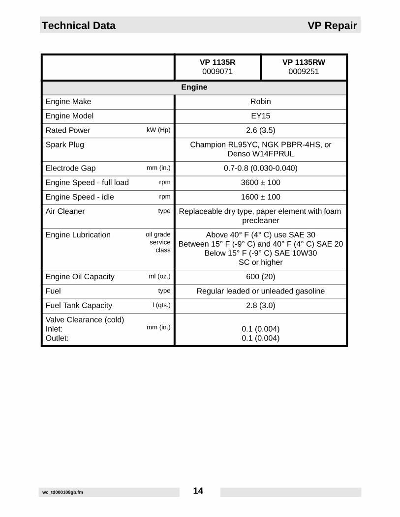
VP 1135R0009071
VP 1135RW0009251
Engine
Engine Make Robin
Engine Model EY15
Rated Power kW (Hp) 2.6 (3.5)
Spark Plug Champion RL95YC, NGK PBPR-4HS, or Denso W14FPRUL
Electrode Gap mm (in.) 0.7-0.8 (0.030-0.040)
Engine Speed - full load rpm 3600 ± 100
Engine Speed - idle rpm 1600 ± 100
Air Cleaner type Replaceable dry type, paper element with foam precleaner
Engine Lubrication oil gradeservice
class
Above 40° F (4° C) use SAE 30Between 15° F (-9° C) and 40° F (4° C) SAE 20
Below 15° F (-9° C) SAE 10W30SC or higher
Engine Oil Capacity ml (oz.) 600 (20)
Fuel type Regular leaded or unleaded gasoline
Fuel Tank Capacity l (qts.) 2.8 (3.0)
Valve Clearance (cold)Inlet:Outlet:
mm (in.) 0.1 (0.004)0.1 (0.004)
wc_td000108gb.fm 14

VP Repair Technical Data
3.5 VP 2050A
VP 2050A0009087
Plate
Weight kg (lbs.) 103 (230)
Exciter Speed rpm 5800 ± 100
Exciter Lubrication ml (oz.) 296 (10)Automatic transmission fluid
Dextron III/Mercon or equivalent
Dimensions mm (in.) 588 (23) x 500 (20) x 884 (35)
VP 2050A0009087
Engine
Engine Make Honda
Engine Model GX 160 K1 QX2
Rated Power kW (Hp) 4.1 (5.5)
Spark Plug NGK BPR 6ES
Electrode Gap mm (in.) 0.7-0.8 (0.028–0.031)
Engine Speed - full load rpm 3600 ± 100
Engine Speed - idle rpm 1600 ± 100
Air Cleaner type Dual element
Engine Lubrication oil grade SAE 10W30SG or SF
Engine Oil Capacity ml (oz.) 600 (20)
Fuel type Regular unleaded gasoline
Fuel Tank Capacity l (qts.) 3.7 (3.9)
Valve Clearance (cold)Inlet:Outlet:
mm (in.) 0.15 (0.006)0.20 (0.008)
wc_td000108gb.fm 15

Technical Data VP Repair
3.6 VP 2050R
VP 2050R0009088
Plate
Weight kg (lbs.) 103 (230)
Exciter Speed rpm 5800 ± 100
Exciter Lubrication ml (oz.) 296 (10)Automatic transmission fluid
Dextron III/Mercon or equivalent
Dimensions mm (in.) 588 (23) x 500 (20) x 778 (31)
wc_td000108gb.fm 16

VP Repair Technical Data
VP 2050R0009088
Engine
Engine Make Robin
Engine Model EY20OYD4540
Rated Power kW (Hp) 3.7 (5.0)
Spark Plug NGK BR6HS or Champion RL86C
Electrode Gap mm (in.) 0.6-0.7 (0.020-0.030)
Engine Speed - full load rpm 3600 ± 100
Engine Speed - idle rpm 1600 ± 100
Air Cleaner type Replaceable dry type, paper element with foam precleaner
Engine Lubrication oil gradeservice
class
Above 40° F (4° C) use SAE 30Between 15° F (-9° C) and 40° F (4° C) SAE 20
Below 15° F (-9° C) SAE 10W30SF or SE
Engine Oil Capacity ml (oz.) 600 (20)
Fuel type Regular leaded or unleaded gasoline
Fuel Tank Capacity l (qts.) 3.8 (4.0)
Valve Clearance (cold)Inlet:Outlet:
mm (in.) 0.1 (0.004)0.1 (0.004)
wc_td000108gb.fm 17

Technical Data VP Repair
3.7 VP 2050Y
VP 2050Y0009089, 0009090
Plate
Weight kg (lbs.) 113 (250)
Exciter Speed rpm 5800 ± 100
Exciter Lubrication ml (oz.) 296 (10)Automatic transmission fluid
Dextron III/Mercon or equivalent
Dimensions mm (in.) 588 (23) x 500 (20) x 884 (35)
wc_td000108gb.fm 18

VP Repair Technical Data
VP 2050Y0009089
Engine
Engine Make Yanmar
Engine Model L48EE
Rated Power kW (Hp) 3.5 (4.7)
Engine Speed - full load rpm 3600 ± 100
Engine Speed - idle rpm 1600 ± 100
Air Cleaner type Replaceable dry type, paper element
Engine Lubrication oil grade SAE 10W30 SAE 20W40 - CC/CD rated
Engine Oil Capacity ml (oz.) 800 (27)
Fuel type No. 2 Diesel - cetane > 45
Fuel Tank Capacity l (qts.) 2.5 (2.7)
Valve Clearance (cold) mm (in.) 0.15 (0.006)
wc_td000108gb.fm 19

Technical Data VP Repair
VP 2050Y0009090
Engine
Engine Make Yanmar
Engine Model L40AE-D
Rated Power kW (Hp) 3.1 (4.2)
Engine Speed - full load rpm 3600 ± 100
Engine Speed - idle rpm 1600 ± 100
Air Cleaner type Replaceable dry type, paper element
Engine Lubrication oil grade SAE 10W30 SAE 20W40 - CC/CD rated
Engine Oil Capacity ml (oz.) 800 (27)
Fuel type No. 2 Diesel - cetane > 45
Fuel Tank Capacity l (qts.) 2.5 (2.7)
Valve Clearance (cold) mm (in.) 0.15 (0.006)
wc_td000108gb.fm 20

VP Repair General
4. General
4.1 Application
This plate is designed for compacting loose, granular soils, gravel, andpaving stones. It is intended to be used in confined areas and areasnext to structures such as walls, curbs, and foundations. Platesequipped with water tanks can be used for compacting asphalt.
This plate is not recommended for compacting cohesive soils with aheavy clay content. For cohesive soil, use a vibratory rammer orsheepsfoot roller.
wc_tx000275gb.fm 21

General VP Repair
4.2 Periodic Maintenance Schedule
Dailybefore
starting
Afterfirst
20 hrs.
Every 2 weeks
or 50 hrs.
Every month
or 100 hrs.
Every yearor
300 hrs.
Check fuel level. •
Check engine oil level. •
Inspect fuel lines. •
Inspect air filter. Replace as needed. •
Check and tighten external hardware. •
Check and adjust drive belt. • •
Clean air cleaner elements. •
Inspect shockmounts for damage. •
Change engine oil. • •
Clean cooling system. •
Clean sediment cup / fuel filter. •
Check and clean spark plug. •
Check and adjust valve clearance. •
Change exciter oil. •
wc_tx000275gb.fm 22

VP Repair Baseplate
5. Baseplate
5.1 Exploded View - VP
wc_tx000276gb.fm 23

Baseplate VP Repair
Parts ListRef. Description Qty Ref. Description Qty
1 Baseplate 35mm 1 32 Screw M10x25 2
2 Console 1 33 Screw M12x75 2
3 Engine 1 34 Nut-lock BM8 1
4 Shaft-exciter 1 35 Nut-lock M8 4
5 Cap-end w/hole 1 36 Nut-lock M12 2
6 Cap-end w/o hole 1 37 Washer 2
7 Beltguard-back 1 38 Washer 5/16 2
8 Beltguard-front 1 39 Washer-lock 6
9 Guide-handle 1 40 Washer-lock B8 4
10 Clutch-centrifugal 1 41 Washer B8.4 4
11 Pulley-exciter 1 42 Washer-lock 2
12 Belt-V A30 1 44 Kit-molding 1
13 Bearing-ball 2 47 Plug-cap #1, tapered 3
14 Shockmount 4 50 Seal-shaft 1
15 Handle-lifting 1 51 Screw M8x35 2
16 Nameplate 1 54 Screw M12x25 1
18 Mount-beltguard 2 55 Seal-ring 12x18 1
19 Console-bar 1 81 Drain-oil 1
20 Bushing-handle 2 82 Handle-lift cage 1
21 Bushing-handle, rubber 2 88 Shockmount 2
25 O-Ring 2 89 Screw M8x12 ISO7380 2
27 Screw #3-48x5/32 4 90 Washer-steel, flat 1
28 Screw M6x12 6 120 Screw, tapping 4x8 2
29 Screw M8x16 6 121 Baffle-muffler, complete 1
30 Screw M8x25 2 122 Key A5x5x33 1
31 Screw M8x55 4
wc_tx000276gb.fm 24

VP Repair Baseplate
Recommended Tools* Assembly Notes
Allen Wrench: 6 mm, 14 mm Gear Puller
Socket: 1/2 in., 1-1/4 in., 13 mm, 19 mm Torque Wrench
Open End Wrench: 13 mm, 19 mm Arbor Press
Screwdriver Oil: Automatic transmission fluid (Dextron III, Mercon or equivalent)
Ref. Sealant Loctite (Omnifit)
Torque Nm (ft.lbs.) Ref. Sealant
Loctite (Omnifit)Torque
Nm (ft.lbs.)
5 S10 33 --- 38 (28)
6 S10 34 S5 20 (15)
14 S3 38 (28) 35 20 (15)
28 S3 8 (6) 51 --- 20 (15)
29 20 (15) 54 S3 20 (15)
30 S3 20 (15) 89 S3 20 (15)
32 S3 49 (36) 20 (15)
** in.lbs.
wc_tx000276gb.fm 25
Baseplate VP Repair
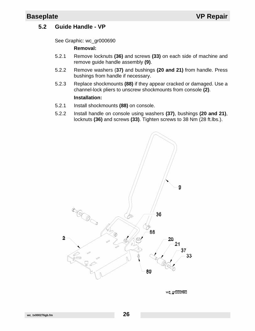
5.2 Guide Handle - VP
See Graphic: wc_gr000690
Removal:
5.2.1 Remove locknuts (36) and screws (33) on each side of machine andremove guide handle assembly (9).
5.2.2 Remove washers (37) and bushings (20 and 21) from handle. Pressbushings from handle if necessary.
5.2.3 Replace shockmounts (88) if they appear cracked or damaged. Use achannel-lock pliers to unscrew shockmounts from console (2).
Installation:
5.2.1 Install shockmounts (88) on console.
5.2.2 Install handle on console using washers (37), bushings (20 and 21),locknuts (36) and screws (33). Tighten screws to 38 Nm (28 ft.lbs.).
wc_tx000276gb.fm 26

VP Repair Baseplate
5.3 Drive Belt
See Graphic: wc_gr000714
Removal:
5.3.1 Remove screws (51) and washers (40 and 41) to remove beltguard(8). Keep screws captive in the belt guard.
5.3.2 Loosen the four nuts (35) which hold the engine to the console, and thescrew (84) which holds the beltguard back to the console.
5.3.3 Slide the engine forward to loosen the belt. Remove belt (12).
Installation:
5.3.1 Install belt on exciter pulley.
5.3.2 Slide the engine backward (towards the handle) to tighten the belt.Adjust the belt so that it deflects 6–8 mm (1/4–3/8 in.) when pressedmidway between the belt pulleys.
5.3.3 Tighten the four nuts (35) which hold the engine to the console, andthe screw (84) which holds the beltguard back to the console.
5.3.4 Make sure that the clutch pulley (10) and the exciter pulley (11) are inalignment. Place a straight edge against the exciter pulley (11) andmove the engine so that the two pulleys are parallel.
5.3.5 Install screws (51) and washers (40 and 41) to reattach beltguard (8).Torque all nuts and screws to 20 Nm (15 ft.lbs.) as you reassemble themachine.
Adjustment:
On new machines or after installing a new belt, check the belt tensionafter first 20 hours of operation. Check and adjust the belt every 50hours thereafter.
wc_tx000276gb.fm 27

Baseplate VP Repair
wc_tx000276gb.fm 28
VP Repair Baseplate
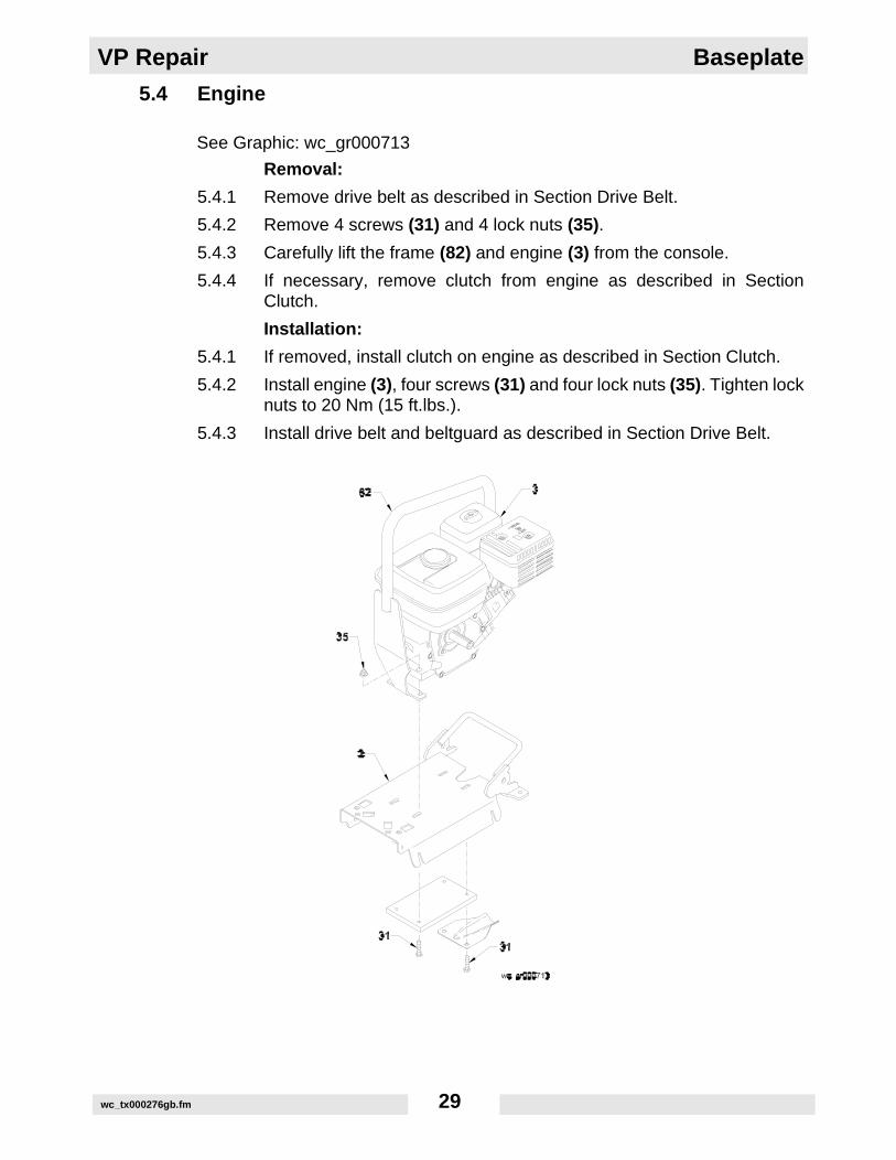
5.4 Engine
See Graphic: wc_gr000713
Removal:
5.4.1 Remove drive belt as described in Section Drive Belt.
5.4.2 Remove 4 screws (31) and 4 lock nuts (35).
5.4.3 Carefully lift the frame (82) and engine (3) from the console.
5.4.4 If necessary, remove clutch from engine as described in SectionClutch.
Installation:
5.4.1 If removed, install clutch on engine as described in Section Clutch.
5.4.2 Install engine (3), four screws (31) and four lock nuts (35). Tighten locknuts to 20 Nm (15 ft.lbs.).
5.4.3 Install drive belt and beltguard as described in Section Drive Belt.
wc_tx000276gb.fm 29
Exciter VP Repair
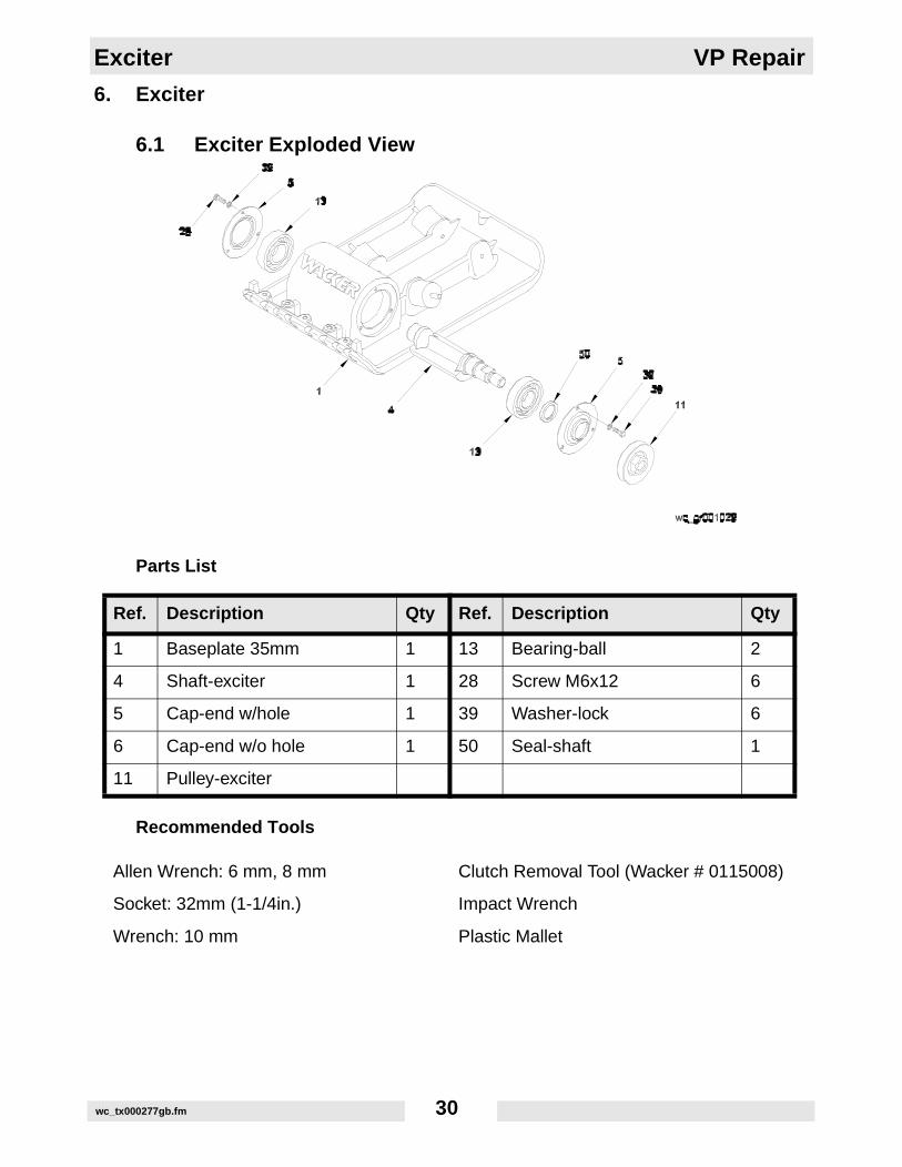
6. Exciter
6.1 Exciter Exploded View
Parts List
Recommended Tools
Ref. Description Qty Ref. Description Qty
1 Baseplate 35mm 1 13 Bearing-ball 2
4 Shaft-exciter 1 28 Screw M6x12 6
5 Cap-end w/hole 1 39 Washer-lock 6
6 Cap-end w/o hole 1 50 Seal-shaft 1
11 Pulley-exciter
Allen Wrench: 6 mm, 8 mm Clutch Removal Tool (Wacker # 0115008)
Socket: 32mm (1-1/4in.) Impact Wrench
Wrench: 10 mm Plastic Mallet
wc_tx000277gb.fm 30
VP Repair Exciter
6.2 Exciter
See Graphic: wc_gr001029
Disassembly:
6.2.1 Remove drive belt as described in Section Drive Belt.
Disconnect or remove spark plug to avoid accidentally starting enginewhen turning pulley. On diesel engines make sure throttle control iscompletely closed.
6.2.2 Exciter pulley (11) is assembled to shaft using left hand thread. Use 32mm (1-1/4 in.) socket on impact wrench and turn pulley clockwise toremove.
6.2.3 Remove clutch and backplate as described in Section Clutch.
6.2.4 Remove three hex head screws (28) securing right side end cap (5) toexciter housing.
6.2.5 Tap opposite end of exciter shaft using a plastic mallet until right sideend-cap (5) and bearing holder (13) breaks free of housing. Beforeremoving exciter shaft, tap shaft back into the exciter to remove the leftside end-cap (6). Remove left side bearing holder (13) and excitershaft (4).
Assembly:
6.2.1 Install exciter assembly. Oil bearings (13). Install belt side bearingholder first. Apply Loctite 232 (or equivalent) to screw threads (28) andsecure bearing holders to exciter housing. Torque screws to 8 Nm (6ft.lbs.).
6.2.2 Install clutch and backplate as described in Section Clutch.
6.2.3 Install exciter pulley (11).
6.2.4 Install drive belt and beltguard as described in Section Drive Belt.
6.2.5 Fill exciter with oil, before operating. See Technical Data for oil quantityand type.
Ref. Sealant Loctite (Omnifit)
Torque Nm (ft.lbs.) Ref. Sealant
Loctite (Omnifit)Torque
Nm (ft.lbs.)
5 S10 28 S3 8 (6)
6 S10
WARNING
wc_tx000277gb.fm 31

Clutch VP Repair
7. Clutch
7.1 Clutch
See Graphic: wc_gr000766
Recommended Tool: Clutch Removal Tool (Wacker # 0115008)
Removal:
7.1.1 Remove drive belt as described in Section Drive Belt.
7.1.2 Remove screw (30) and washers (38) securing clutch (10) to engineshaft. Remove clutch from engine shaft using the clutch removal tool(4). Use care not to damage clutch during removal.
7.1.3 If necessary, remove screw (84) and washers (85, 40) to removebeltguard plate (7).
Installation:
7.1.1 If removed, install beltguard plate (7) using washers (85, 40) and screw(84).
7.1.2 Apply Loctite 242 to threads of screw (30). Secure clutch assembly(10) to engine shaft using washers (38) and screw (30). Tighten screwto 20 Nm (15 ft.lbs.).
7.1.3 Install drive belt and beltguard as described in Section Drive Belt.
wc_tx000278gb.fm 32
VP Repair Clutch
7.2 Clutch Engagement Speed Test
Take care when testing machine with beltguard removed to avoidloose clothing, jewelery, long hair, etc., from getting caught in rotatingparts. Replace beltguard after testing and before operating machine.
7.2.1 Remove beltguard as described in Section Drive Belt.
7.2.2 Put machine on a rubber test mat to prevent it from moving.
7.2.3 Start engine and allow it to warm up.
7.2.4 Pull throttle to full speed. Allow the exciter to reach full speed for a fewseconds, then return to idle.
7.2.5 Attach tachometer and slowly increase engine speed. Note the enginespeed reading when clutch pulley starts to rotate. Correct clutch speedis 2300 ± 100 RPM.
7.2.6 If clutch engagement is below 2000 RPM, check for weak springs. Ifclutch engagement is over 2200 RPM, clutch may be worn and requirereplacement, or exciter belt may be binding.
WARNING
wc_tx000278gb.fm 33

Water System VP Repair
8. Water System
8.1 Water System Exploded View - VP
wc_tx000279gb.fm 34

VP Repair Water System
Parts ListRecommended Tools
* Assembly Notes
Ref. Description Qty Ref. Description Qty
1 Screw M6 X 12 1 11 Tank-Water 1
2 Screw M8 X 20 3 12 Cap-Water Tank 1
3 Washer-Lock B6 1 13 Clamp-”Pinch-On” 1
4 Washer-Lock 4 14 Manifold-Water Assembly 1
5 Nut-Lock,M8 Clip 4 14A Plug-Pipe 2
6 Clamp 6-1/2"Nom, T-Bolt 2 14B Fitting-Elbow 1
7 Molding 3/4"X 15.50", Rubber 2 15 Bracket-Tank Assembly 1
8 Clamp 1 16 Valve-Shutoff 1
9 Hose 3/16" X 13" 1 17 Screw M8X25 DIN933 4
10 Washer-Lock B8 3
Socket: 13 mm, 19 mm Pliers
Wrench: 13 mm
Ref. Sealant Loctite (Omnifit)
Torque Nm (ft.lbs.) Ref. Sealant
Loctite (Omnifit)Torque
Nm (ft.lbs.)
2 --- 8.1 (6) 17 --- 20 (15)
wc_tx000279gb.fm 35

Troubleshooting VP Repair
9. Troubleshooting
Problem / Symptom Reason / Remedy
Plate does not develop full speed. Poor compaction.
• Engine throttle control not completely open.
• Throttle control not adjusted correctly.
• Ground too wet, plate sticking. Allow soil to dry before compacting.
• Drive belt loose or worn, slipping on pulleys. Adjust or replace belt. Check that engine mounting bolts are tight.
• Exciter bearings binding. Check condition and level of oil in exciter. Add or change oil.
• Air filter clogged with dust, reducing engine perfor-mance. Clean or replace air filter.
• Engine speed too low. Check engine speed with tachometer. Adjust or repair engine to run at correct speed. Refer to engine manual.
Engine running, no vibration • Engine throttle not open.
• Drive belt loose or broken. Adjust or replace.
• Clutch damaged. Inspect and replace clutch.
• Engine speed too low. Check engine speed.
• Too much oil in exciter. Adjust oil to correct level.
Plate jumps or compacts unevenly.
• Ground surface too hard.
• Shockmounts loose or damaged.
wc_tx000279gb.fm 36

Threadlockers and Sealants
Threadlockers and Sealants
Threadlocking adhesives and sealants are specified throughout thismanual by a notation of “S” plus a number (S#) and should be usedwhere indicated. Threadlocking compounds normally break down attemperatures above 175°C (350°F). If a screw or bolt is hard toremove, heat it using a small propane torch to break down the sealant.When applying sealants, follow instructions on container. The sealantslisted below are recommended for use on Wacker equipment.
TYPE( ) = Europe COLOR USAGE
PART NO. - SIZE
Loctite 222Hernon 420Omnifit 1150 (50M)
Purple Low strength, for locking threads smaller than 6 mm (1/4").Hand tool removable.Temp. range, -54 to 149 ° C (-65 to 300 ° F)
73287 - 10 ml
Hernon 423Omnifit 1350 (100M)
Blue Medium strength, for locking threads larger than 6 mm (1/4").Hand tool removable.Temp. range, -54 to 149 ° C (-65 to 300 ° F)
29311 - .5 ml17380 - 50 ml
Loctite 271/277Hernon 427Omnifit 1550 (220M)
Red High strength, for all threads up to 25 mm (1”).Heat parts before disassembly.Temp. range, -54 to 149 ° C (-65 to 300 ° F)
29312 - .5 ml26685 - 10 ml73285 - 50 ml
Loctite 290Hernon 431Omnifit 1710 (230LL)
Green Medium to high strength, for locking preassembled threads and for sealing weld porosity (wicking).Gaps up to 0.13 mm (0.005")Temp. range, -54 to 149 ° C (-65 to 300 ° F)
28824 - .5 ml25316 - 10 ml
Loctite 609Hernon 822Omnifit 1730 (230L)
Green Medium strength retaining compound for slip or press fit of shafts, bearings, gears, pulleys, etc.Gaps up to 0.13 mm (0.005")Temp. range, -54 to 149 ° C (-65 to 300 ° F)
29314 - .5 ml
Loctite 545Hernon 947Omnifit 1150 (50M)
Brown Hydraulic sealantTemp. range, -54 to 149 ° C (-65 to 300 ° F)
79356 - 50 ml
Loctite 592Hernon 920Omnifit 790
White Pipe sealant with Teflon for moderate pressures.Temp. range, -54 to 149 ° C (-65 to 300 ° F)
26695 - 6 ml73289 - 50 ml
Loctite 515Hernon 910Omnifit 10
Purple Form-in-place gasket for flexible joints.Fills gaps up to 1.3 mm (0.05")Temp. range, -54 to 149 ° C (-65 to 300 ° F)
70735 - 50 ml
Loctite 496Hernon 110Omnifit Sicomet 7000
Clear Instant adhesive for bonding rubber, metal and plas-tics; general purpose. For gaps up to 0.15 mm (0.006")Read caution instructions before using.Temp. range, -54 to 82 ° C (-65 to 180 ° F)
52676 - 1 oz.

Threadlockers and Sealants
Loctite Primer THernon Primer 10Omnifit VC Activator
AerosolSpray
Fast curing primer for threadlocking, retaining andsealing compounds. Must be used with stainless steel hardware. Recommended for use with gasket sealants.
2006124 - 6 oz.
TYPE( ) = Europe COLOR USAGE
PART NO. - SIZE

Torque Values
Torque Values
Metric Fasteners (DIN)
TORQUE VALUES (Based on Bolt Size and Hardness) WRENCH SIZE
Size ft.lb. Nm ft.lb. Nm ft.lb. Nm Inch Metric Inch Metric
M3 *11 1.2 *14 1.6 *19 2.1 7/32 5.5 - 2.5
M4 *26 2.9 *36 4.1 *43 4.9 9/32 7 - 3
M5 *53 6.0 6 8.5 7 10 5/16 8 - 4
M6 7 10 10 14 13 17 - 10 - 5
M8 18 25 26 35 30 41 1/2 13 - 6
M10 36 49 51 69 61 83 11/16 17 - 8
M12 63 86 88 120 107 145 3/4 19 - 10
M14 99 135 140 190 169 230 7/8 22 - 12
M16 155 210 217 295 262 355 15/16 24 - 14
M18 214 290 298 405 357 485 1-1/16 27 - 14
M20 302 410 427 580 508 690 1-1/4 30 - 17
1 ft.lb. = 1.357 Nm. * = in.lb. 1 Inch = 25.4 mm
8.8 10.9 12.9

Torque Values
Inch Fasteners (SAE)
Size ft.lb. Nm ft.lb. Nm ft.lb. Nm Inch Metric Inch Metric
No.4 *6 0.7 *14 1.0 *12 1.4 1/4 5.5 3/32 -
No.6 *12 1.4 *17 1.9 *21 2.4 5/16 8 7/64 -
No.8 *22 2.5 *31 3.5 *42 4.7 11/32 9 9/64 -
No.10 *32 3.6 *45 5.1 *60 6.8 3/8 - 5/32 -
1/4 6 8.1 9 12 12 16 7/16 - 3/32 -
5/16 13 18 19 26 24 33 1/2 13 1/4 -
3/8 23 31 33 45 43 58 9/16 - 5/16 -
7/16 37 50 52 71 69 94 5/8 16 3/8 -
1/2 57 77 80 109 105 142 3/4 19 3/8 -
9/16 82 111 115 156 158 214 13/16 - - -
5/8 112 152 159 216 195 265 15/16 24 1/2 -
3/4 200 271 282 383 353 479 1-1/8 - 5/8 -
1 ft.lb. = 1.357 Nm. * = in.lb. 1 Inch = 25.4 mm


Wacker Construction Equipment AG · Preußenstraße 41 · D-80809 München · Tel.: +49-(0)89-354 02 - 0 · Fax: +49 - (0)89-354 02-390Wacker Corporation · P.O. Box 9007 · Menomonee Falls, WI 53052-9007 · Tel. : +1-(1)(262) 255-0500 · Fax: +1-(1)(262) 255-0550 · Tel. : (800) 770-0957Wacker Asia Pacific Operations · Sunley Center, Unit 912, 9/F · 9 Wing Qin Street, Kwai Chung, N.T. · Hong Kong · Tel. + 852 2406 60 32 · Fax: + 852 2406 60 21


![22.10.2010 SVN Accounts [NPFL094:/] … vojtech.diatka = rw ejemr = rw machacekmatous = rw sedlak = rw masekj = rw.](https://static.fdocuments.us/doc/165x107/56649e115503460f94afcb54/22102010httpufalmffcuniczcoursenpfl0941-svn-accounts-npfl094.jpg)