SINGLE-DECK ISLAND MERCHANDISER
40
OWIZ/OWIZV OWEZ/OWEZV P080658A V.1 R.02 08/12 COMPONENT SINGLE-DECK ISLAND MERCHANDISER INSTALLATION & OPERATIONS MANUAL General Information ........................................ 2 Case Installation ........................................... 3-4 Case Connections ........................................... 5 Pre-Power Checklist ......................................... 6 Airflow & Defrost ............................................. 7 Cleaning & Maintenance ................................. 8 Appendices ...................................................... 9 Table of Contents To ensure proper functionality and optimum performance, it is STRONGLY recommended that Hill PHOENIX display cases be installed/serviced by qualified technicians who have experience working with commercial refrigerated display merchandisers and storage cabinets. For a list of Hill PHOENIX-authorized installation/service contractors, please visit our Web site at www.hillphoenix.com.
Transcript of SINGLE-DECK ISLAND MERCHANDISER

OWIZ/OWIZVOWEZ/OWEZV
P080658AV.1 R.02
08/12COMPONENT
SINGLE-DECK ISLAND MERCHANDISERINSTALLATION & OPERATIONS MANUAL
General Information ........................................ 2Case Installation ...........................................3-4Case Connections ........................................... 5Pre-Power Checklist ......................................... 6
Airflow & Defrost ............................................. 7Cleaning & Maintenance ................................. 8Appendices ...................................................... 9
Table of Contents
To ensure proper functionality and optimum performance, it is STRONGLY recommended that Hill PHOENIX display cases be installed/serviced by qualified technicians who have experience working with commercial refrigerated display merchandisers and storage cabinets. For a list of Hill PHOENIX-authorized installation/service contractors, please visit our Web site at www.hillphoenix.com.
Version 1Rev. 0 (02/12)• new manual formatRev. 1 (04/12)• removed Dual Temp (Fans Off) wiring from AppendixRev. 2 (07/12)• correct TOC errorsRev. 3 (08/12)• updated Wiring Diagrams
Copyright © 2012 by Hill PHOENIX
All rights reserved. No part of this document may reproduced or transmitted in any form or by any means - i.e., electronic or mechanical, including photocopying, recording or any other information storage and retrieval system - without express written permission from Hill PHOENIX.
REVISION HISTORY
ii
IMPORTANT NOTICES
LIABILITY NOTICEFor Cases with Shelf Lighting SystemsHill PHOENIX® does NOT design any of its shelf lighting sys-tems or any of its display cases with shelf lighting systems for direct or indirect exposure to water or other liquids. The use of a misting system or water hose on a display case with a shelf lighting system, resulting in the direct or indi-rect exposure of the lighting system to water, can lead to a number of serious issues (including, without limitation, elec-trical failures, fire, electric shock, and mold) in turn resulting in personal injury, death, sickness, and/or serious property damage (including, without limitation, to the display itself, to the location where the display is situated [e.g., store] and to any surrounding property). DO NOT use misting systems, water hoses or other devices that spray liquids in Hill PHOE-NIX display cases with lighted shelves.
If a misting system or water hose is installed or used on a display case with a shelf lighting system, then Hill PHOENIX shall not be subject to any obligations or liabili-ties (whether arising out of breach of contract, warranty, tort [including negligence], strict liability or other theories of law) directly or indirectly resulting from, arising out of or related to such installation or use, including, without limitation, any personal injury, death or property damage resulting from an electrical failure, fire, electric shock, or mold.
P079211M, REVO
R-744 (CO2) NOTICEFor Systems Utilizing R-744 (CO2) RefrigerantFor refrigeration units that utilize R-744 (CO2), pressure relief and pressure-regulating relief valves may need to be installed based on the system capacity. The valves need to be located such that no stop valve is positioned between the relief valves and the parts or section of the system being protected.
When de-energizing refrigeration units containing R-744 (CO2), venting of the R-744 (CO2) refrigerant may occur through the pressure regulating relief valves. These valves are located on the refrigeration system and not on the case model. If venting does occur, the valve must not be defeat-ed, capped, or altered by any means.
WARNING: UNDER NO CIRCUMSTANCES should any component be replaced or added without consulting Hill PHOENIX Field Service Engineering. Utilizing improper components may result in serious injury to persons or damage to the system.
D A N G E RIndicates an immediate threat of death or serious injury if all instructions are not fol-lowed carefully.
▲�
W A R N I N GIndicates a potential threat of death or seri-ous injury if all instructions are not followed carefully.
▲�
C A U T I O NIndicates that failure to properly follow in-structions may result in case damage.
▲�
SAFETY NOTICEAt Hill PHOENIX, the safety of our customers and em-ployees, as well as the ongoing performance of our products, are top priorities. To that end, we include important warning messages in all Hill PHOENIX instal-lation and operations handbooks, accompanied by an alert symbol paired with the word "DANGER", "WARNING", or "CAUTION".
All warning messages will inform you of the potential hazard; how to reduce the risk of case damage, person-al injury or death; and what may happen if the instruc-tions are not properly followed.
iii
GENERAL INFORMATION
Thank you for choosing Hill PHOENIX for your food merchandising needs. This handbook contains important technical information and will assist you with the installation and operation of your new Hill PHOENIX display cases. By closely fol-lowing the instructions, you can expect peak performance; attractive fit and finish; and long case life.
We are always interested in your suggestions for improvements (e.g. case design, technical documents, etc.). Please feel free to contact our Marketing Services group at the toll-free number listed below. Thank you for choosing Hill PHOENIX, and we wish you the very best in outstanding food merchandising.
CASE DESCRIPTIONThis manual covers the OWIZ, OWIZV, OWEZ and OWEZV single-deck island merchandisers (for electrical data and case dimensions, see Appendices A–D).
STORE CONDITIONSHill PHOENIX cases are designed to operate in an air-con-ditioned store that maintains a 75°F (24°C) store tempera-ture and 55% (max) relative humidity (CRMA conditions). Case operation will be adversely affected by exposure to excessively high ambient temperatures and/or humidity.
REFRIGERATION SYSTEM OPERATIONAir-cooled condensing units require adequate ventilation for efficient performance. Machine-room temperatures must be maintained at a minimum of 65°F in winter and a maximum of 95°F in summer. Minimum condensing temperatures should be no less than 70°F.
RECEIVING CASESExamine fixtures carefully and in the event of shipping dam-age and/or shortages, please contact the Service Parts Department at 1-800-283-1109.
CASE DAMAGEClaims for obvious damage must be 1) noted on either the freight bill or the express receipt and 2) signed by the carri-er's agent; otherwise, the carrier may refuse the claim. If damage becomes apparent after the equipment is unpacked, retain all packing materials and submit a written request to the carrier for inspection within 14 days of receipt of the equipment.
LOST/MISSING ITEMSEquipment has been carefully inspected to insure the high-est level of quality. Any claim for lost/missing items must be made to Hill PHOENIX within 48 hours of receipt of the equipment.
SERVICE & TECHNICAL SUPPORTFor service or technical questions regarding display cases, please contact our Case Division Customer Service Department at the toll-free number listed below. For ques-tions regarding our refrigeration systems or electrical distri-bution centers, please contact our Systems Division Customer Service Department at 1-770-388-0706.
PARTS ORDERINGIf you need to contact Hill PHOENIX regarding specific fix-tures/parts, call 1-800-283-1109 and ask for a Service Parts Representative. Provide the following information about the part you are ordering:
• Model number and serial number* of the case for which the part is intended.
• Length of the part (if applicable).• Color of part (if painted) or color of polymer part.• Whether part is for left- or right-hand application.• Quantity
*Serial plate is located inside the case on the top-left side.
If the parts are to be returned for credit, ask the Parts Department to furnish you with a Return Material Authorization Number.
HILL PHOENIX1925 Ruffin Mill Rd.
Colonial Heights, VA 23834Mon.-Fri. (8 a.m to 5 p.m EST)
Tel: 1-800-283-1109Fax: 804-526-7450
Web site: www.hillphoenix.com
NOTEInstallation of 3rd-party materials may result in diminished case performance.
2
MOVING CASESHill PHOENIX display cases are generally shipped to stores with casters installed on the base frame. The casters make the job of moving cases easier for everyone involved in the shipping and installation process, as well as reducing the chance of damage from raising and lowering cases with ”J” bars to place them on dollies, skates or rollers. In most situ-ations, one or two persons can easily move the case into position.
When the cases arrive at the store, simply roll them on to the store floor to the proper staging area. Occasionally, cases are shipped with skid boards attached to help with stabilization. In these instances, the casters should be attached after the case is removed from the truck.
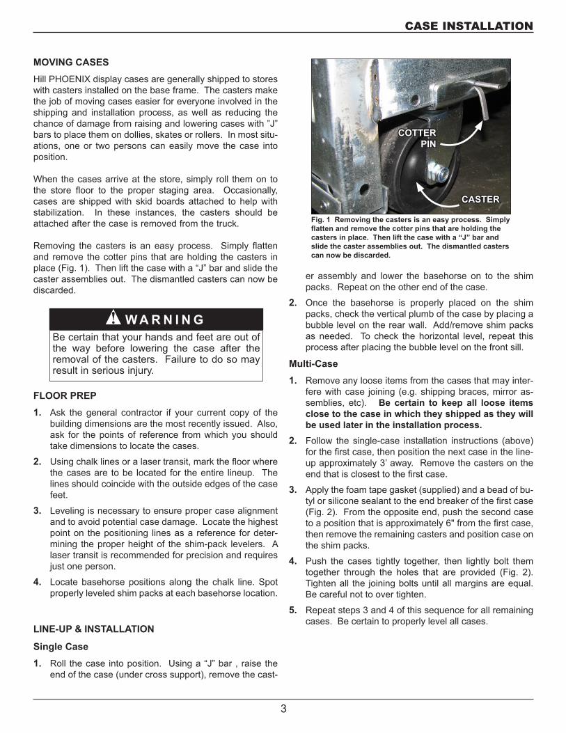
Removing the casters is an easy process. Simply flatten and remove the cotter pins that are holding the casters in place (Fig. 1). Then lift the case with a “J” bar and slide the caster assemblies out. The dismantled casters can now be discarded.
FLOOR PREP1. Ask the general contractor if your current copy of the
building dimensions are the most recently issued. Also, ask for the points of reference from which you should take dimensions to locate the cases.
2. Using chalk lines or a laser transit, mark the floor where the cases are to be located for the entire lineup. The lines should coincide with the outside edges of the case feet.
3. Leveling is necessary to ensure proper case alignment and to avoid potential case damage. Locate the highest point on the positioning lines as a reference for deter-mining the proper height of the shim-pack levelers. A laser transit is recommended for precision and requires just one person.
4. Locate basehorse positions along the chalk line. Spot properly leveled shim packs at each basehorse location.
W A R N I N GBe certain that your hands and feet are out of the way before lowering the case after the removal of the casters. Failure to do so may result in serious injury.
▲�
LINE-UP & INSTALLATION
Single Case1. Roll the case into position. Using a “J” bar , raise the
end of the case (under cross support), remove the cast-
er assembly and lower the basehorse on to the shim packs. Repeat on the other end of the case.
2. Once the basehorse is properly placed on the shim packs, check the vertical plumb of the case by placing a bubble level on the rear wall. Add/remove shim packs as needed. To check the horizontal level, repeat this process after placing the bubble level on the front sill.
Multi-Case1. Remove any loose items from the cases that may inter-
fere with case joining (e.g. shipping braces, mirror as-semblies, etc). Be certain to keep all loose items close to the case in which they shipped as they will be used later in the installation process.
2. Follow the single-case installation instructions (above) for the first case, then position the next case in the line-up approximately 3’ away. Remove the casters on the end that is closest to the first case.
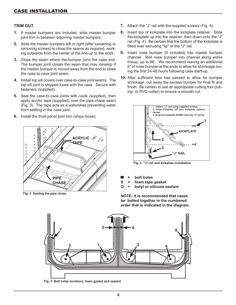
3. Apply the foam tape gasket (supplied) and a bead of bu-tyl or silicone sealant to the end breaker of the first case (Fig. 2). From the opposite end, push the second case to a position that is approximately 6" from the first case, then remove the remaining casters and position case on the shim packs.
4. Push the cases tightly together, then lightly bolt them together through the holes that are provided (Fig. 2). Tighten all the joining bolts until all margins are equal. Be careful not to over tighten.
5. Repeat steps 3 and 4 of this sequence for all remaining cases. Be certain to properly level all cases.
Fig. 1 Removing the casters is an easy process. Simply flatten and remove the cotter pins that are holding the casters in place. Then lift the case with a “J” bar and slide the caster assemblies out. The dismantled casters can now be discarded.
CASTER
COTTER PIN
CASE INSTALLATION
3
TRIM OUT1. If master bumpers are included, slide master bumper
joint trim in between adjoining master bumpers.
2. Slide the master bumpers left or right (after loosening or removing screws) to close the seams as required, work-ing outwards from the center of the line-up to the ends.
3. Close the seam where the bumper joins the case end. The bumper joint closes the seam that may develop if the master bumper is moved away from the end to close the case-to-case joint seam.
4. Install top sill covers over case-to-case joint seams. The top sill joint is shipped loose with the case. Secure with fasteners (supplied).
5. Seal the case-to-case joints with caulk (supplied), then apply acrylic tape (supplied) over the pipe-chase seam (Fig. 3). The tape acts as a watershed preventing water from settling in the case joint.
6. Install the front panel joint trim (ships loose).
7. Attach the “J” rail with the supplied screws (Fig. 4).
8. Insert top of kickplate into the kickplate retainer. Slide the kickplate up into the retainer, then down onto the “J” rail (Fig. 4). Be certain that the bottom of the kickplate is fitted over extruding "lip" of the "J" rail.
9. Insert nose bumper (if included) into master bumper channel. Roll nose bumper into channel along entire lineup, up to 96’. We recommend leaving an additional 6" of nose bumper at the ends to allow for shrinkage dur-ing the first 24-48 hours following case start-up.
10. After sufficient time has passed to allow for bumper shrinkage, cut away the excess bumper for final fit and finish. Be certain to use an appropriate cutting tool (tub-ing- or PVC-cutter) to ensure a smooth cut.
Fig. 4 "J" rail and kickplate installation
1. Attach "J" rail using supplied screws.2. Slide kickplate UP into kickplate retainer recess.3. Drop the kickplate DOWN onto the "J" rail lip.
KICKPLATE
3
2
"J" RAIL
1
= bolt holesX = foam tape gasketO = butyl or silicone sealant
NOTE: It is recommended that cases be bolted together in the numbered order that is indicated in the diagram.
XXXXXXXXXXXXXXXXXXXXXXXX XX
XXXXXXXXXXXXXXXXXXXXXXXXXXXXXXXXXXXXXXXXXXXXXXXXXXXXXXXXXXXXXXXXXXXXXXXXXXXXXXXXXXXXXXXXXXXXX
XXXX
XXXX
XXXX
XXXX
XXXX
XXXX
XXXXXXXXXXXXX XXXXXXXX XXXXX XXXXX XXXX
o ooooooooooooooooooooooooooooooooooooooooooooooooooooooooooo
oooo
oooo
oooo
oooo
o o
oooo
o
oooooooooooooooooooooooooooooooooooooooooo
ooo
oo
oooooooooo ooooo
oooooooooo
o ooooooooooooooooooooooooooooooooooooooooooooooooooooooooooo
ooooooooooooooooo oooooo
oooooooooooooooooooooooooooooooooooooooooo
ooooo
ooooooooooooooooo
oooooooo
Fig. 2 Bolt holes locations; foam gasket and sealant
5 6
1 23 4
7 8
Fig. 3 Sealing the pipe chase
ACRYLICTAPE
PIPE CHASE
CASE INSTALLATION
4
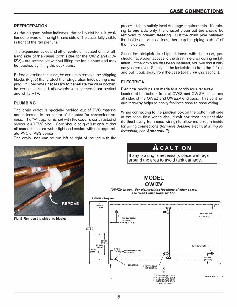
REFRIGERATIONAs the diagram below indicates, the coil outlet hole is posi-tioned forward on the right-hand side of the case, fully visible in front of the fan plenum.
The expansion valve and other controls - located on the left-hand side of the cases (both sides for the OWIZ and OW-IZV) - are accessible without lifting the fan plenum and may be reached by lifting the deck pans.
Before operating the case, be certain to remove the shipping blocks (Fig. 5) that protect the refrigeration lines during ship-ping. If it becomes necessary to penetrate the case bottom, be certain to seal it afterwards with canned-foam sealant and white RTV.
PLUMBINGThe drain outlet is specially molded out of PVC material and is located in the center of the case for convenient ac-cess. The “P” trap, furnished with the case, is constructed of schedule 40 PVC pipe. Care should be given to ensure that all connections are water-tight and sealed with the appropri-ate PVC or ABS cement.The drain lines can be run left or right of the tee with the
proper pitch to satisfy local drainage requirements. If drain-ing to one side only, the unused clean out tee should be removed to prevent freezing. Cut the drain pipe between the inside and outside tees, then cap the piping stub off of the inside tee.
Since the kickplate is shipped loose with the case, you should have open access to the drain line area during instal-lation. If the kickplate has been installed, you will find it very easy to remove. Simply lift the kickplate up from the "J" rail and pull it out, away from the case (see Trim Out section).
ELECTRICALElectrical hookups are made to a continuous raceway located at the bottom-front of OWIZ and OWIZV cases and all sides of the OWEZ and OWEZV end caps. This continu-ous raceway helps to easily facilitate case-to-case wiring.
When connecting to the junction box on the bottom-left side of the case, field wiring should exit box from the right side (furthest away from case wiring) to allow more room inside for wiring connections (for more detailed electrical wiring in-formation, see Appendix E).
C A U T I O NIf any brazing is necessary, place wet rags around the area to avoid tank damage.
▲�
MODELOWIZV
NOTES: * STUB-UP AREA ** RECOMMENDED STUP-UP CENTERLINE FOR ELECTRICAL AND HUB DRAINS
- SUCTION LINE - 7/8", LIQUID LINE - 1/2"
ELECTRICAL
3 in [7.6 cm]
WIRING TO RACEWAY(STANDARD)
82 1/2 in [209.6 cm]
29 7/8 in [75.9 cm]
37 1/2 in [95.3 cm]
41 1/4 in [104.8 cm]
ELECTRICAL
REFRIGERATION(OPTIONAL)
REFRIGERATION
6 in [15.2 cm]
13 5/8 in [34.7 cm]
8 5/8 in [22.0 cm]
13 5/8 in [34.7 cm]
5 7/8 in [14.9 cm]
1 1/2 in [3.8 cm]
120 in [304.8 cm] { 10' CASE }96 in [243.8 cm] { 8' CASE }
144in [365.8cm] { 12' CASE }
72 in [182.9 cm] { 6' CASE }
LC1 1/2" PVC DRAIN
CONNECTION
FRONT OF CASE
(OWIZV shown. For piping/wiring locations of other cases, see Case Dimensions section.
Fig. 5 Remove the shipping blocks
REMOVE
CASE CONNECTIONS
5
PRE-POWER CHECKLIST
Before powering-up the case, be certain that all of the steps listed below have been completed to ensure proper case functionality, safety and compliance with warranty terms.
Have you thoroughly examined the case for shipping damage? (see pg. 2)
Have you removed and discarded the casters? (see pg. 3)
Have you checked the vertical plumb of the case? The horizontal level? (see pg. 3)
Have you applied the foam tape gasket and sealant to the end breakers of adjoining cases? (see pg. 4)
Have you sealed the case-to-case joints by applying caulk and acrylic tape to the pipe-chase seam? (see pg. 4)
Have you sealed any tank penetrations? (see pg. 5)
Have you removed the shipping blocks from the refrigeration lines? (see pg. 5)
6
AIR FLOW & PRODUCT LOAD
Hill PHOENIX cases provide maximum product capacity within the refrigerated air envelope. Please keep products within the load limit line shown on the diagram below.
It is important that you do not overload the food product dis-play so that it impinges on the air flow pattern. Overloading will cause malfunction and the loss of proper temperature levels, particularly when discharge and return air sections are covered.
DEFROST & TEMPERATURE CONTROLS
Hill PHOENIX cases utilize electric, hot gas, or timed-off defrost. The primary components used for the defrost cycle are the various defrost termination sensors, which work to terminate the defrost cycle in the case. These controls may include 1) a Klixon® thermostat, 2) a sensor probe, or 3) a dial-type thermostat with sensor bulb (the thermostat will always be mounted with the electrical controls of the case - i.e., in the electrical junction box, in the electrical raceway, etc.).
If electric defrost is used, the defrost termination sensor will be located either behind the rear baffle or mounted to the coil. If hot gas defrost is used, the defrost termination sen-sor will be mounted to the dump line - the sensor should always be mounted on the coil-side of the check valve or solenoid valve. Finally, if timed-off defrost is used, the refrig-
eration cycle is simply turned off by the case controls for a specified amount of time; therefore, there are generally no active defrost components utilized.
The discharge air probe monitors the temperature of the discharge air and may be used as the defrost termination sensor. The probe can generally be found behind the rear baffle, in the upper baffle, or in front of the honeycomb.
NOTE: if the discharge air probe is used for defrost termina-tion, none of the termination sensors listed earlier will be installed in the case.
For more detailed information on suggested defrost times and settings, see Appendices A–D . Further adjustment may be required depending on store conditions.
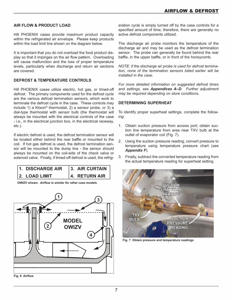
DETERMINING SUPERHEAT
To identify proper superheat settings, complete the follow-ing:
1. Obtain suction pressure from access port; obtain suc-tion line temperature from area near TXV bulb at the outlet of evaporator coil (Fig. 7).
2. Using the suction pressure reading, convert pressure to temperature using temperature pressure chart (see Appendix F).
3. Finally, subtract the converted temperature reading from the actual temperature reading for superheat setting.
Fig. 7 Obtain pressure and temperature readings
SUCTIONLINE TEMPREADING
TXVBULB SUCTION
PRESSUREREADING
1. DISCHARGE AIR2. LOAD LIMIT
3. AIR CURTAIN4. RETURN AIR
OWIZV shown. Airflow is similar for other case models.
AIRFLOW & DEFROST
1
MODELOWIZV
3
2
Fig. 6 Airflow
4
7
CLEANING PROCEDURES
• A periodic cleaning schedule should be established to maintain proper sanitation, insure maximum operating efficiency, and avoid the corrosive action of food fluids on metal parts that are left on for long periods of time. We recommend cleaning once a week.
• To avoid shock hazard, be sure all electrical power is turned off before cleaning. In some installations, more than one disconnect switch may have to be turned off to completely de-energize the case.
• All surfaces pitch downward to a deep-drawn drain trough, funneling liquids to the front of the case where the waste outlet is located in front of the fan plenum. Check waste outlet to ensure that it is not clogged be-fore starting the cleaning process and avoid introducing water faster than the case drain can carry it away.
• The coil and fan plenum are easily accessible when cleaning is required. Simply unscrew along the edges, then swing the fan plenum cover up, thus exposing both the coil and fan plenum. Be certain that both the ple-num and coil cover are properly closed and secured af-ter cleaning to avoid air leaks.
• If any potentially harmful cleaners are used, be certain to provide a temporary separator (e.g., cardboard, plastic wrap, etc.) between those cases that are being cleaned and those that may still contain product.
• Avoid spraying cleaning solutions directly on electrical connections.
• Allow cases to be turned off long enough to clean any frost or ice from coil and pans.
• Remove kickplate and clean underneath the case with a broom and a long-handled mop. Use warm water and a disinfecting cleaning solution when cleaning underneath the cases.
D A N G E R▲�SHOCK HAZARD
Always disconnect power to case when servic-ing or cleaning. Failure to do so may result in serious injury or death.
W A R N I N G▲�Exercise extreme caution when working in a case with the coil cover removed. The coil contains many sharp edges that can result in severe cuts to the hands and arms.
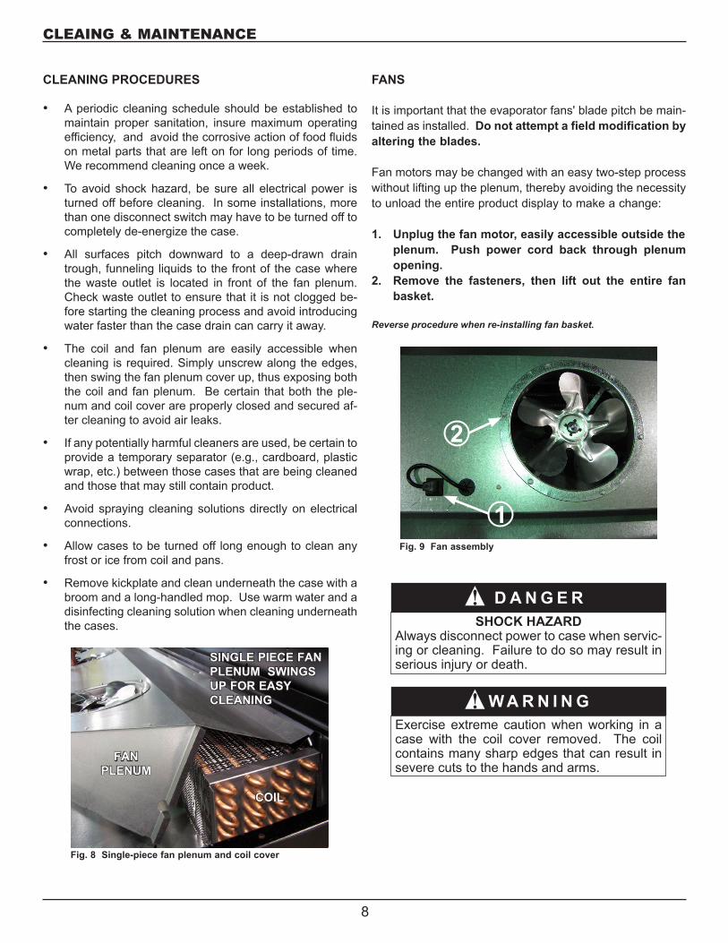
FANS
It is important that the evaporator fans' blade pitch be main-tained as installed. Do not attempt a field modification by altering the blades.
Fan motors may be changed with an easy two-step process without lifting up the plenum, thereby avoiding the necessity to unload the entire product display to make a change:
1. Unplug the fan motor, easily accessible outside the plenum. Push power cord back through plenum opening.
2. Remove the fasteners, then lift out the entire fan basket.
Reverse procedure when re-installing fan basket.
Fig. 8 Single-piece fan plenum and coil cover
SINGLE PIECE FAN PLENUM SWINGS UP FOR EASY CLEANING
FAN PLENUM
COIL
CLEAING & MAINTENANCE
1
2
Fig. 9 Fan assembly
8
APPENDIX
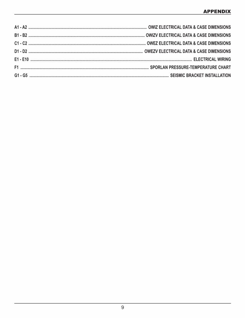
A1 - A2 ...................................................................................................................... OWIZ ELECTRICAL DATA & CASE DIMENSIONSB1 - B2 .................................................................................................................... OWIZV ELECTRICAL DATA & CASE DIMENSIONSC1 - C2 ..................................................................................................................... OWEZ ELECTRICAL DATA & CASE DIMENSIONSD1 - D2 .................................................................................................................. OWEZV ELECTRICAL DATA & CASE DIMENSIONS E1 - E10 ................................................................................................................................................................. ELECTRICAL WIRINGF1 ................................................................................................................................ SPORLAN PRESSURE-TEMPERATURE CHARTG1 - G5 ........................................................................................................................................... SEISMIC BRACKET INSTALLATION
9
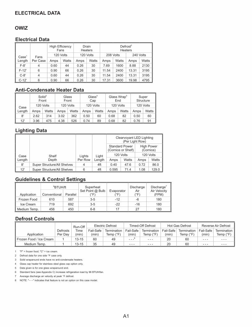
OWIZ
ELECTRICAL DATA
Electrical Data
Case1
LengthFans
Per Case
High EfficiencyFans
DrainHeaters
Defrost2
Heaters120 Volts 120 Volts 208 Volts 240 Volts
Amps Watts Amps Watts Amps Watts Amps WattsF-8' 4 0.60 44 0.26 30 7.69 1600 8.88 2130
F-12' 6 0.90 66 0.26 30 11.54 2400 13.31 3195C-8' 4 0.60 44 0.26 30 11.54 2400 13.31 3195
C-12' 6 0.90 66 0.26 30 17.31 3600 19.98 4795
Guidelines & Control Settings
Application
6BTUH/ft SuperheatSet Point @ Bulb
(°F)Evaporator
(°F)
Discharge Air(°F)
Discharge7
Air Velocity(FPM)Conventional Parallel
Frozen Food 610 587 3-5 -12 -6 180Ice Cream 719 692 3-5 -22 -16 180
Medium Temp. 456 450 6-8 17 27 180
1 "F" = frozen food; "C" = ice cream.
2 Defrost data for one side °F case only.
3 Solid wraparound ends have no anti-condensate heaters.
4 Glass cap heater for stainless steel glass cap option only.
5 Data given is for one glass wraparound end.
6 Standard fans (see Appendix C) increase refrigeration load by 96 BTUH/fan.
7 Average discharge air velocity at peak °F defrost.
8 NOTE: "- - -" indicates that feature is not an option on this case model.
Defrost Controls
ApplicationDefrosts Per Day
Run-OffTime (min)
Electric Defrost Timed-Off Defrost Hot Gas Defrost Reverse Air DefrostFail-Safe
(min)Termination Temp (°F)
Fail-Safe (min)
Termination Temp (°F)
Fail-Safe (min)
Termination Temp (°F)
Fail-Safe (min)
Termination Temp (°F)
Frozen Food / Ice Cream 1 13-15 60 49 - - -8 - - - 20 60 - - - - - -Medium Temp. 1 13-15 35 49 - - - - - - 20 60 - - - - - -
Lighting Data
Anti-Condensate Heater Data
CaseLength
Solid3
FrontGlass Front
Glass4
CapGlass Wrap5
EndSuper
Structure120 Volts 120 Volts 120 Volts 120 Volts 120 Volts
Amps Watts Amps Watts Amps Watts Amps Watts Amps Watts8' 2.62 314 3.02 362 0.50 60 0.68 82 0.50 60
12' 3.96 475 4.38 526 0.74 89 0.68 82 0.76 91
CaseLength
ShelfDepth
LightsPer Row
LightLength
Clearvoyant LED Lighting(Per Light Row)
Standard Power(Cornice or Shelf)
High Power(Cornice)
120 Volts 120 VoltsAmps Watts Amps Watts
8' Super Structure/All Shelves 4 4ft 0.40 47.6 0.72 86.012' Super Structure/All Shelves 6 4ft 0.595 71.4 1.08 129.0
A1
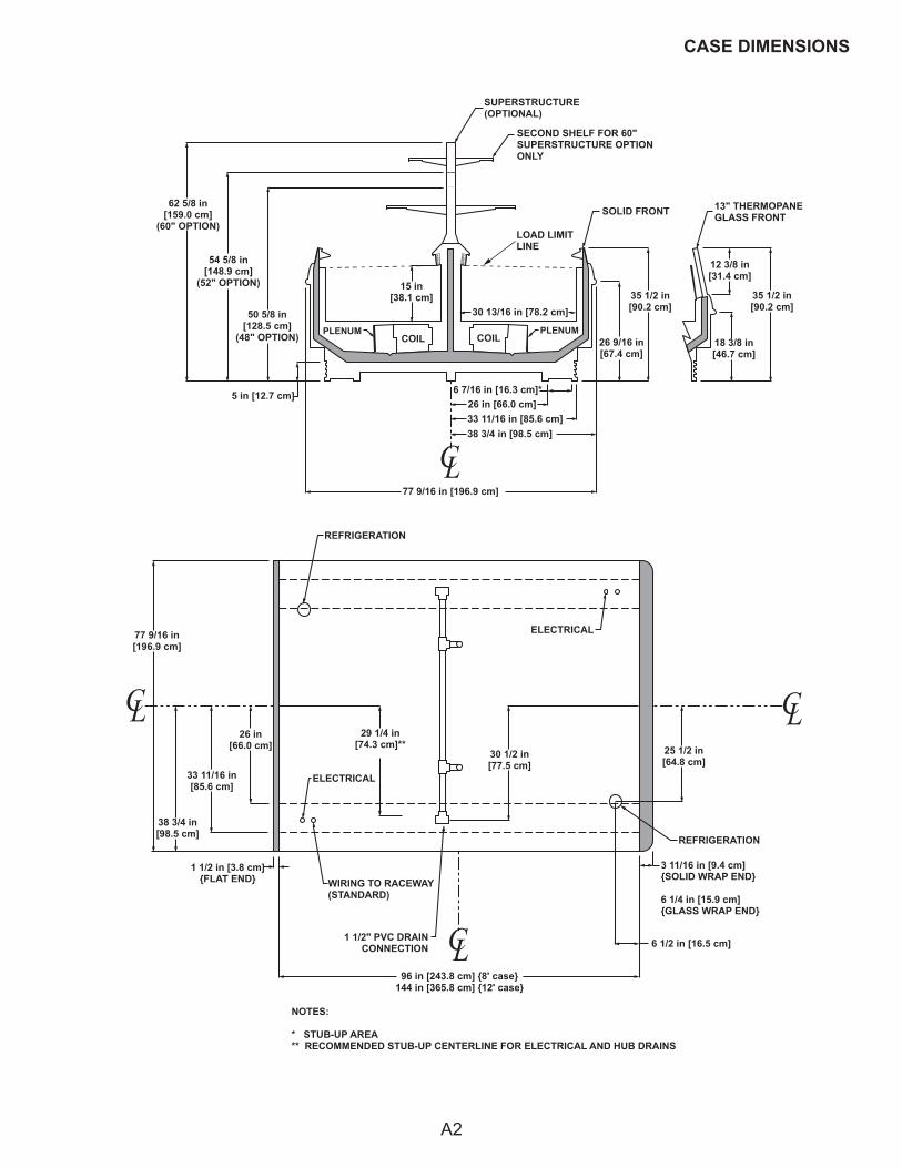
CASE DIMENSIONS
18 3/8 in[46.7 cm]
13" THERMOPANEGLASS FRONT
35 1/2 in[90.2 cm]
12 3/8 in[31.4 cm]
35 1/2 in[90.2 cm]
26 9/16 in[67.4 cm]
SOLID FRONT
COILPLENUM
COILPLENUM
15 in[38.1 cm]
30 13/16 in [78.2 cm]
5 in [12.7 cm]
62 5/8 in[159.0 cm]
(60" OPTION)
54 5/8 in[148.9 cm]
(52" OPTION)
50 5/8 in[128.5 cm]
(48" OPTION)
SUPERSTRUCTURE(OPTIONAL)
SECOND SHELF FOR 60"SUPERSTRUCTURE OPTIONONLY
77 9/16 in [196.9 cm]
C L
96 in [243.8 cm] {8' case}144 in [365.8 cm] {12' case}
C L C L
C L
6 7/16 in [16.3 cm]*26 in [66.0 cm]33 11/16 in [85.6 cm]38 3/4 in [98.5 cm]
REFRIGERATION
ELECTRICAL77 9/16 in[196.9 cm]
38 3/4 in[98.5 cm]
33 11/16 in[85.6 cm]
26 in[66.0 cm]
1 1/2 in [3.8 cm]{FLAT END}
ELECTRICAL
WIRING TO RACEWAY(STANDARD)
1 1/2" PVC DRAINCONNECTION
29 1/4 in[74.3 cm]**
30 1/2 in[77.5 cm]
6 1/2 in [16.5 cm]
3 11/16 in [9.4 cm]{SOLID WRAP END}
6 1/4 in [15.9 cm]{GLASS WRAP END}
REFRIGERATION
25 1/2 in[64.8 cm]
NOTES:
* STUB-UP AREA** RECOMMENDED STUB-UP CENTERLINE FOR ELECTRICAL AND HUB DRAINS • SUCTION LINE - 7/8", LIQUID LINE - 3/8" • AVAILABLE SHELF SIZES: 10", 12", 14", & 16" • DASHED LINES SIGNIFY AREA INSIDE BASE RAIL BEHIND KICK-PLATE
LOAD LIMITLINE
A2
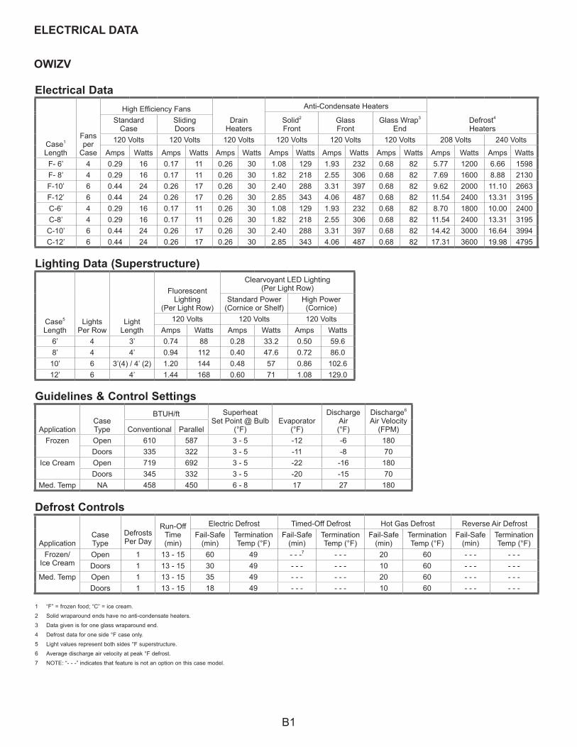
OWIZV
ELECTRICAL DATA
Electrical Data
Case1
Length
Fans per
Case
High Efficiency FansDrain
Heaters
Anti-Condensate Heaters
Defrost4
HeatersSolid2
FrontGlass Front
Glass Wrap3
EndStandard
CaseSlidingDoors
120 Volts 120 Volts 120 Volts 120 Volts 120 Volts 120 Volts 208 Volts 240 Volts
Amps Watts Amps Watts Amps Watts Amps Watts Amps Watts Amps Watts Amps Watts Amps WattsF- 6’ 4 0.29 16 0.17 11 0.26 30 1.08 129 1.93 232 0.68 82 5.77 1200 6.66 1598F- 8’ 4 0.29 16 0.17 11 0.26 30 1.82 218 2.55 306 0.68 82 7.69 1600 8.88 2130F-10’ 6 0.44 24 0.26 17 0.26 30 2.40 288 3.31 397 0.68 82 9.62 2000 11.10 2663F-12’ 6 0.44 24 0.26 17 0.26 30 2.85 343 4.06 487 0.68 82 11.54 2400 13.31 3195C-6’ 4 0.29 16 0.17 11 0.26 30 1.08 129 1.93 232 0.68 82 8.70 1800 10.00 2400C-8’ 4 0.29 16 0.17 11 0.26 30 1.82 218 2.55 306 0.68 82 11.54 2400 13.31 3195
C-10’ 6 0.44 24 0.26 17 0.26 30 2.40 288 3.31 397 0.68 82 14.42 3000 16.64 3994C-12’ 6 0.44 24 0.26 17 0.26 30 2.85 343 4.06 487 0.68 82 17.31 3600 19.98 4795
1 “F” = frozen food; “C” = ice cream.
2 Solid wraparound ends have no anti-condensate heaters.
3 Data given is for one glass wraparound end.
4 Defrost data for one side °F case only.
5 Light values represent both sides °F superstructure.
6 Average discharge air velocity at peak °F defrost.
7 NOTE: “- - -” indicates that feature is not an option on this case model.
Defrost Controls
ApplicationCaseType
Defrosts Per Day
Run-OffTime (min)
Electric Defrost Timed-Off Defrost Hot Gas Defrost Reverse Air DefrostFail-Safe
(min)Termination Temp (°F)
Fail-Safe (min)
Termination Temp (°F)
Fail-Safe (min)
Termination Temp (°F)
Fail-Safe (min)
Termination Temp (°F)
Frozen/Ice Cream
Open 1 13 - 15 60 49 - - -7 - - - 20 60 - - - - - -Doors 1 13 - 15 30 49 - - - - - - 10 60 - - - - - -
Med. Temp Open 1 13 - 15 35 49 - - - - - - 20 60 - - - - - -Doors 1 13 - 15 18 49 - - - - - - 10 60 - - - - - -
Case5
LengthLights
Per RowLight
Length
FluorescentLighting
(Per Light Row)
Clearvoyant LED Lighting(Per Light Row)
Standard Power(Cornice or Shelf)
High Power(Cornice)
120 Volts 120 Volts 120 VoltsAmps Watts Amps Watts Amps Watts
6’ 4 3’ 0.74 88 0.28 33.2 0.50 59.68’ 4 4’ 0.94 112 0.40 47.6 0.72 86.0
10’ 6 3’(4) / 4’ (2) 1.20 144 0.48 57 0.86 102.612’ 6 4’ 1.44 168 0.60 71 1.08 129.0
Lighting Data (Superstructure)
Guidelines & Control Settings
ApplicationCaseType
BTUH/ft SuperheatSet Point @ Bulb
(°F)Evaporator
(°F)
Discharge Air(°F)
Discharge6
Air Velocity(FPM)Conventional Parallel
Frozen Open 610 587 3 - 5 -12 -6 180Doors 335 322 3 - 5 -11 -8 70
Ice Cream Open 719 692 3 - 5 -22 -16 180Doors 345 332 3 - 5 -20 -15 70
Med. Temp NA 458 450 6 - 8 17 27 180
B1
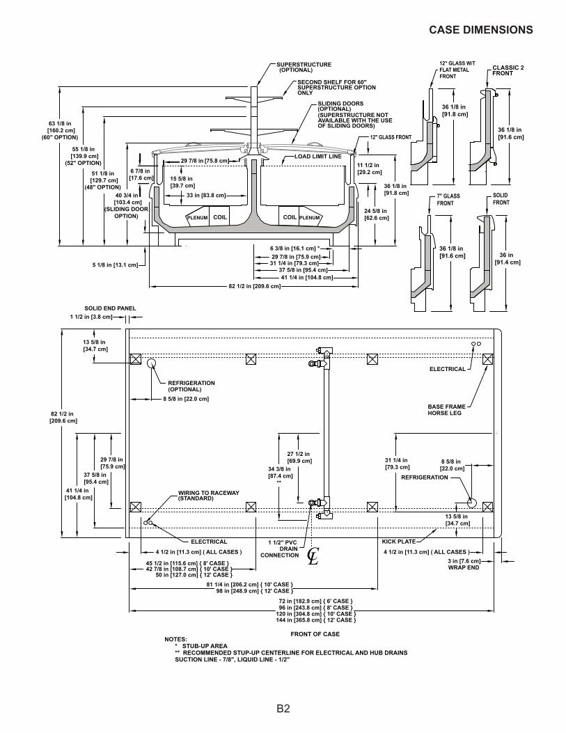
CASE DIMENSIONS
SLIDING DOORS(OPTIONAL)(SUPERSTRUCTURE NOTAVAILABLE WITH THE USEOF SLIDING DOORS)
55 1/8 in [139.9 cm]
(52" OPTION)
63 1/8 in [160.2 cm]
(60" OPTION)
51 1/8 in [129.7 cm]
(48" OPTION)40 3/4 in
[103.4 cm](SLIDING DOOR
OPTION)
33 in [83.8 cm]
15 5/8 in [39.7 cm]
82 1/2 in [209.6 cm]
24 5/8 in [62.6 cm]
29 7/8 in [75.9 cm]6 3/8 in [16.1 cm] *
5 1/8 in [13.1 cm]
ELECTRICAL
6 7/8 in [17.6 cm]
3 in [7.6 cm]WRAP END
SOLID END PANEL
37 5/8 in [95.4 cm]41 1/4 in [104.8 cm]
31 1/4 in [79.3 cm]
4 1/2 in [11.3 cm] ( ALL CASES )
50 in [127.0 cm] { 12' CASE }
98 in [248.9 cm] { 12' CASE }
42 7/8 in [108.7 cm] { 10' CASE }
81 1/4 in [206.2 cm] { 10' CASE }
45 1/2 in [115.6 cm] { 8' CASE }
4 1/2 in [11.3 cm] ( ALL CASES )
WIRING TO RACEWAY(STANDARD)
82 1/2 in [209.6 cm]
36 1/8 in [91.8 cm]
37 5/8 in [95.4 cm]
41 1/4 in [104.8 cm]
ELECTRICAL
REFRIGERATION(OPTIONAL)
REFRIGERATION
29 7/8 in [75.8 cm]11 1/2 in [29.2 cm]
29 7/8 in [75.9 cm]
BASE FRAME HORSE LEG
KICK PLATE
31 1/4 in [79.3 cm]
8 5/8 in [22.0 cm]
27 1/2 in [69.9 cm]
34 3/8 in [87.4 cm]
**
13 5/8 in [34.7 cm]
8 5/8 in [22.0 cm]
13 5/8 in [34.7 cm]
1 1/2 in [3.8 cm]
120 in [304.8 cm] { 10' CASE }96 in [243.8 cm] { 8' CASE }
144 in [365.8 cm] { 12' CASE }
72 in [182.9 cm] { 6' CASE }
12" GLASS FRONT
LOAD LIMIT LINE
SUPERSTRUCTURE(OPTIONAL)
SECOND SHELF FOR 60"SUPERSTRUCTURE OPTIONONLY
COIL PLENUMPLENUM COIL
LC1 1/2" PVC
DRAINCONNECTION
FRONT OF CASENOTES: * STUB-UP AREA ** RECOMMENDED STUP-UP CENTERLINE FOR ELECTRICAL AND HUB DRAINS SUCTION LINE - 7/8", LIQUID LINE - 1/2"
36 in [91.4 cm]
36 1/8 in [91.6 cm]
7" GLASS FRONT
SOLID FRONT
36 1/8 in [91.8 cm]
36 1/8 in [91.6 cm]
CLASSIC 2FRONT
12" GLASS W/T FLAT METAL FRONT
B2
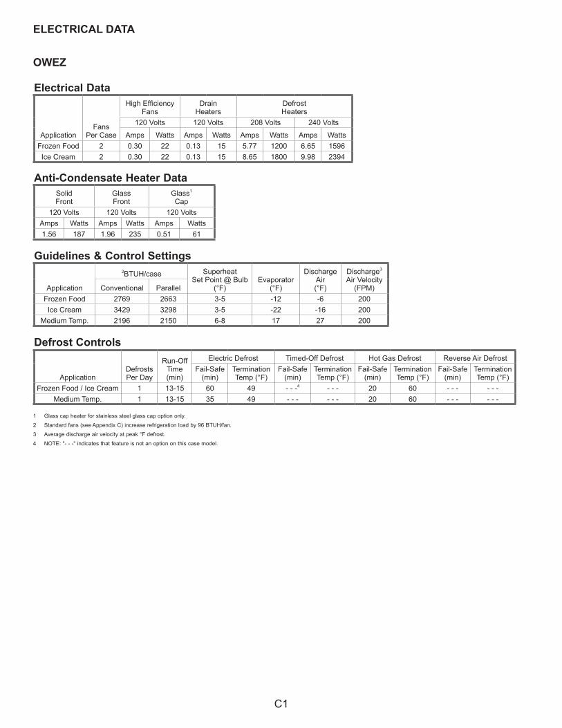
OWEZ
ELECTRICAL DATA
Electrical Data
ApplicationFans
Per Case
High EfficiencyFans
DrainHeaters
DefrostHeaters
120 Volts 120 Volts 208 Volts 240 Volts
Amps Watts Amps Watts Amps Watts Amps WattsFrozen Food 2 0.30 22 0.13 15 5.77 1200 6.65 1596Ice Cream 2 0.30 22 0.13 15 8.65 1800 9.98 2394
Guidelines & Control Settings
Application
2BTUH/case SuperheatSet Point @ Bulb
(°F)Evaporator
(°F)
Discharge Air(°F)
Discharge3
Air Velocity(FPM)Conventional Parallel
Frozen Food 2769 2663 3-5 -12 -6 200Ice Cream 3429 3298 3-5 -22 -16 200
Medium Temp. 2196 2150 6-8 17 27 200
1 Glass cap heater for stainless steel glass cap option only.
2 Standard fans (see Appendix C) increase refrigeration load by 96 BTUH/fan.
3 Average discharge air velocity at peak °F defrost.
4 NOTE: "- - -" indicates that feature is not an option on this case model.
Defrost Controls
Anti-Condensate Heater DataSolidFront
Glass Front
Glass1
Cap120 Volts 120 Volts 120 Volts
Amps Watts Amps Watts Amps Watts1.56 187 1.96 235 0.51 61
ApplicationDefrosts Per Day
Run-OffTime (min)
Electric Defrost Timed-Off Defrost Hot Gas Defrost Reverse Air DefrostFail-Safe
(min)Termination Temp (°F)
Fail-Safe (min)
Termination Temp (°F)
Fail-Safe (min)
Termination Temp (°F)
Fail-Safe (min)
Termination Temp (°F)
Frozen Food / Ice Cream 1 13-15 60 49 - - -4 - - - 20 60 - - - - - -Medium Temp. 1 13-15 35 49 - - - - - - 20 60 - - - - - -
C1
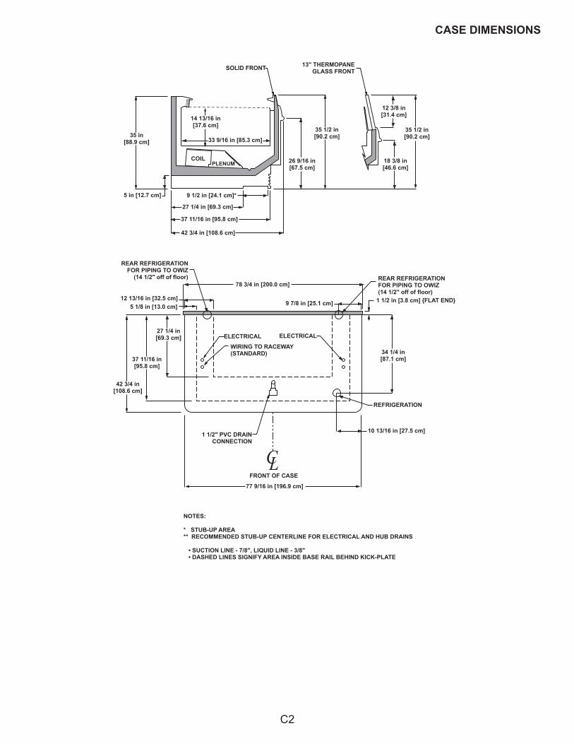
CASE DIMENSIONS
35 in[88.9 cm]
5 in [12.7 cm]
27 1/4 in [69.3 cm]
37 11/16 in [95.8 cm]
42 3/4 in [108.6 cm]
9 1/2 in [24.1 cm]*
COILPLENUM
14 13/16 in[37.6 cm]
33 9/16 in [85.3 cm]
SOLID FRONT
26 9/16 in[67.5 cm]
35 1/2 in[90.2 cm]
18 3/8 in[46.6 cm]
35 1/2 in[90.2 cm]
12 3/8 in[31.4 cm]
13" THERMOPANEGLASS FRONT
42 3/4 in[108.6 cm]
37 11/16 in[95.8 cm]
27 1/4 in[69.3 cm]
12 13/16 in [32.5 cm]5 1/8 in [13.0 cm]
REAR REFRIGERATIONFOR PIPING TO OWIZ
(14 1/2" off of floor)
ELECTRICAL
WIRING TO RACEWAY(STANDARD)
ELECTRICAL
1 1/2" PVC DRAINCONNECTION
REFRIGERATION
10 13/16 in [27.5 cm]
34 1/4 in[87.1 cm]
1 1/2 in [3.8 cm] {FLAT END}
REAR REFRIGERATIONFOR PIPING TO OWIZ(14 1/2" off of floor)
78 3/4 in [200.0 cm]
9 7/8 in [25.1 cm]
FRONT OF CASE
77 9/16 in [196.9 cm]
C L
NOTES:
* STUB-UP AREA** RECOMMENDED STUB-UP CENTERLINE FOR ELECTRICAL AND HUB DRAINS • SUCTION LINE - 7/8", LIQUID LINE - 3/8" • DASHED LINES SIGNIFY AREA INSIDE BASE RAIL BEHIND KICK-PLATE
C2
OWEZV
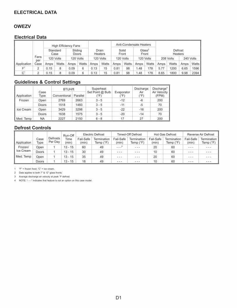
ELECTRICAL DATA
Electrical Data
Application
Fans per
Case
High Efficiency FansDrain
Heaters
Anti-Condensate Heaters
DefrostHeaters
SolidFront
Glass2
FrontStandard
CaseSlidingDoors
120 Volts 120 Volts 120 Volts 120 Volts 120 Volts 208 Volts 240 Volts
Amps Watts Amps Watts Amps Watts Amps Watts Amps Watts Amps Watts Amps WattsF1 2 0.15 8 0.09 6 0.13 15 0.81 98 1.48 178 5.77 1200 6.65 1596C1 2 0.15 8 0.09 6 0.13 15 0.81 98 1.48 178 8.65 1800 9.98 2394
Guidelines & Control Settings
1 “F” = frozen food; “C” = ice cream.
2 Data applies to both 7” & 12” glass fronts.
3 Average discharge air velocity at peak °F defrost.
4 NOTE: “- - -” indicates that feature is not an option on this case model.
Defrost Controls
ApplicationCaseType
Defrosts Per Day
Run-OffTime (min)
Electric Defrost Timed-Off Defrost Hot Gas Defrost Reverse Air DefrostFail-Safe
(min)Termination Temp (°F)
Fail-Safe (min)
Termination Temp (°F)
Fail-Safe (min)
Termination Temp (°F)
Fail-Safe (min)
Termination Temp (°F)
Frozen/Ice Cream
Open 1 13 - 15 60 49 - - -4 - - - 20 60 - - - - - -Doors 1 13 - 15 30 49 - - - - - - 10 60 - - - - - -
Med. Temp Open 1 13 - 15 35 49 - - - - - - 20 60 - - - - - -Doors 1 13 - 15 18 49 - - - - - - 10 60 - - - - - -
ApplicationCaseType
BTUH/ft SuperheatSet Point @ Bulb
(°F)Evaporator
(°F)
Discharge Air(°F)
Discharge3
Air Velocity(FPM)Conventional Parallel
Frozen Open 2769 2663 3 - 5 -12 -6 200Doors 1518 1460 3 - 5 -11 -5 70
Ice Cream Open 3429 3298 3 - 5 -22 -16 200Doors 1638 1575 3 - 5 -20 -14 70
Med. Temp NA 2227 2150 6 - 8 17 27 200
D1
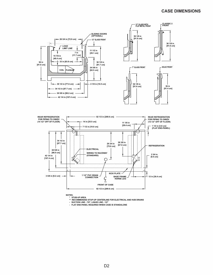
CASE DIMENSIONS
33 in [83.8 cm]36 in [91.6 cm]
36 1/8 in [91.7 cm]
15 7/8 in [40.4 cm]
42 1/4 in [107.4 cm]
4 1/8 in [10.5 cm]
38 5/8 in [98.2 cm]
24 5/8 in [62.5 cm]
11 1/2 in [29.1 cm]
28 3/4 in [72.9 cm] 12" GLASS FRONT
LOAD LIMIT LINE
COIL PLENUM
7 in [17.7 cm]
26 3/8 in [67.0 cm]
11 1/8 in [28.4 cm]
29 3/4 in [75.6 cm]
7 1/2 in [19.0 cm]
82 1/2 in [209.6 cm]
3 5/8 in [9.2 cm]
3 3/4 in [9.4 cm]42 1/4 in
[107.4 cm]
34 1/2 in [87.7 cm]
38 5/8 in [98.0 cm]
34 1/2 in [87.7 cm]
30 1/2 in [77.6 cm]
1 1/2 in [3.8 cm]
82 1/2 in [209.6 cm]
14 in [35.5 cm]
REFRIGERATION
REAR REFRIGERATIONFOR PIPING TO OWIZV
(14 1/2" OFF OF FLOOR)
ELECTRICAL
WIRING TO RACEWAY(STANDARD)
REAR REFRIGERATIONFOR PIPING TO OWIZV(14 1/2" OFF OF FLOOR)
FRONT OF CASE
1 1/2" PVC DRAINCONNECTION
NOTES: * STUB-UP AREA ** RECOMMENDED STUP-UP CENTERLINE FOR ELECTRICAL AND HUB DRAINS - SUCTION LINE - 7/8", LIQUID LINE - 1/2"
KICK PLATEBASE FRAME
HORSE LEG12 in [30.4 cm]C L
SLIDING DOORS(OPTIONAL)
{FLAT END-PANEL}
- FLAT END-PANEL REQUIRED WHEN CASE IS STANDALONE
36 in [91.4 cm]
36 1/8 in [91.6 cm]
7" GLASS FRONT SOLID FRONT
36 1/8 in [91.8 cm]
36 1/8 in [91.6 cm]
CLASSIC 2FRONT12" GLASS WITH
FLAT METAL FRONT
D2
ATTE
NTI
ON
ELEC
TRIC
IAN
:FO
R S
AFET
Y AN
D C
OD
EC
OM
PLIA
NC
E G
RO
UN
DFI
XTU
RE
AT
TIM
E O
FIN
STAL
LATI
ON
:CAU
TIO
N
RIS
K O
F EL
ECTR
ICSH
OC
K. M
OR
E TH
AN O
NE
POW
ER-S
UPP
LY.
DIS
CO
NN
ECT
ALL
POW
ER-S
UPP
LIES
BEFO
RE
SER
VIC
ING
.
P901
598E
- R
4
BLAC
KW
HIT
EBL
UE
RED
YELL
OW
PUR
PLE
OR
ANG
EW
IRE
IDEN
TIFI
CAT
ION
DEF
RO
ST H
EATE
RS
(1-P
HAS
E)D
EFR
OST
HEA
TER
S (3
-PH
ASE)
ANTI
-CO
ND
ENSA
TE H
EATE
RS
AISL
E W
ARM
ERD
RAI
N H
EATE
RPR
IMAR
Y FA
NS
SEC
ON
DAR
Y FA
NS
AMBI
ENT
FAN
SLI
GH
TSBE
LLTE
MPE
RAT
UR
E C
ON
TRO
LD
EFR
OST
TER
MIN
ATIO
N C
ON
TRO
LD
EFR
OST
SAF
ETY
CU
T-O
UT
CO
NTR
OL
LIQ
UID
LIN
E SO
LEN
OID
SUC
TIO
N L
INE
SOLE
NO
IDC
ASE/
CO
NTR
OLL
ER P
OW
ERTR
ANSF
OR
MER
CAP
ACIT
OR
REC
EPTA
CLE
SYST
EM N
EUTR
AL (3
-PH
ASE)
POW
ER C
OR
D (S
ELF-
CO
NTA
INED
)SE
RVI
CE
LIG
HT
(HI-P
RES
SUR
E)H
IGH
PR
ESSU
RE
SWIT
CH
DU
AL P
RES
SUR
E SW
ITC
HC
ON
DEN
SIN
G U
NIT
PO
WER
CO
ND
ENSI
NG
UN
IT F
AN
1,2 L1
L3L2
1314 16
1518
1710
936
374
340
56
78 12
1160
,62
19,2
022
2123
2827
2931
3039
3841
42 2425
3435
3332
N58
5753
,54
49,5
051
,52
4748
4546
44 2
20V
IG R
ECEP
TAC
LEG
FI R
ECEP
TAC
LEH
UM
IDIF
IER
2643
5655
7071
GR
EEN
REF
RIG
ERAT
ED P
AN S
OLE
NO
IDR
EFR
IGER
ATED
PAN
BYP
ASS
SOLE
NO
IDAI
R H
EATE
R D
EFR
OST
SO
LEN
OID
AIR
DEF
RO
ST F
ANM
AIN
SEC
ON
DAR
Y FL
UID
SO
LEN
OID
SEC
ON
DAR
Y C
OO
LAN
T PU
MP
GR
OU
ND
TO
EXT
ERIO
R/F
RAM
E G
RO
UN
D T
O IN
TER
IOR
LIN
ERG
RO
UN
D T
O J
UN
CTI
ON
BO
X
75 77 79 81 83 85
6465
6667
6869
7273
7459
7661
65 2
20V
73 2
20V
GR
OU
ND
TO
LIG
HTS
97
67 2
20V
69 2
20V
TAN
K FL
USH
SO
LEN
OID
MIS
TIN
G S
OLE
NO
IDD
RIP
DO
WN
TIM
ERR
EAR
STO
RAG
E BO
X FA
NS
87 2
20V
89 2
20V 94
908886
87 89 95
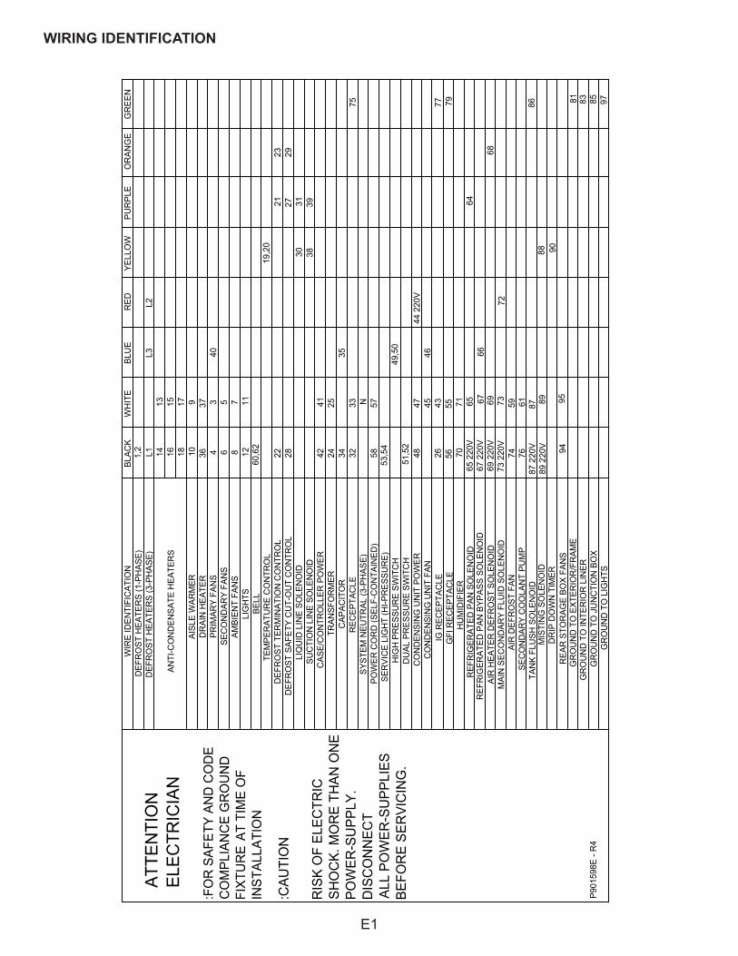
WIRE ID
WIRING IDENTIFICATION
E1
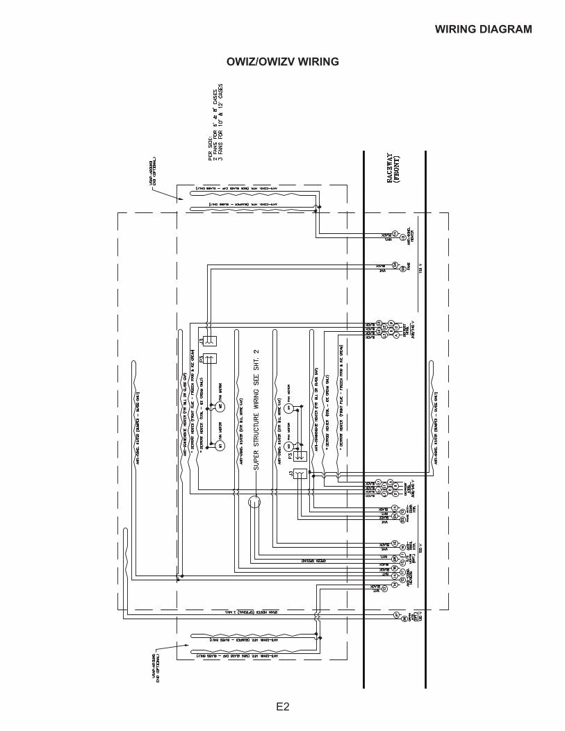
WIRING DIAGRAM
OWIZ/OWIZV WIRING
E2
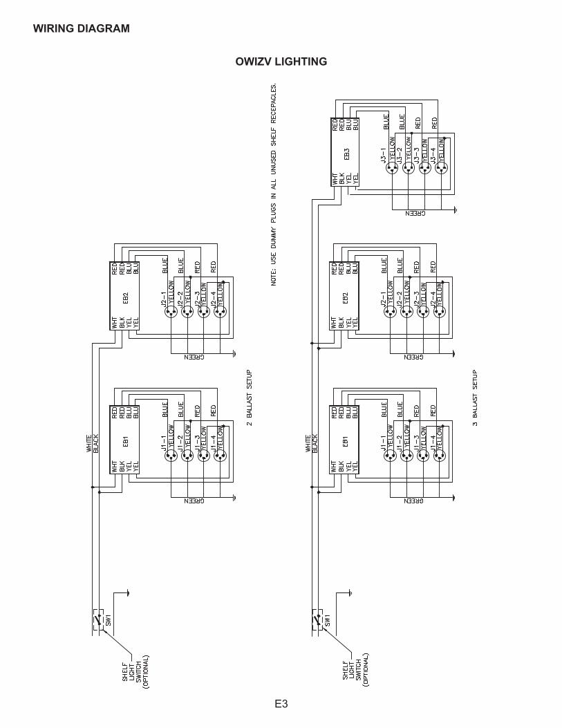
WIRING DIAGRAM
OWIZV LIGHTING
E3
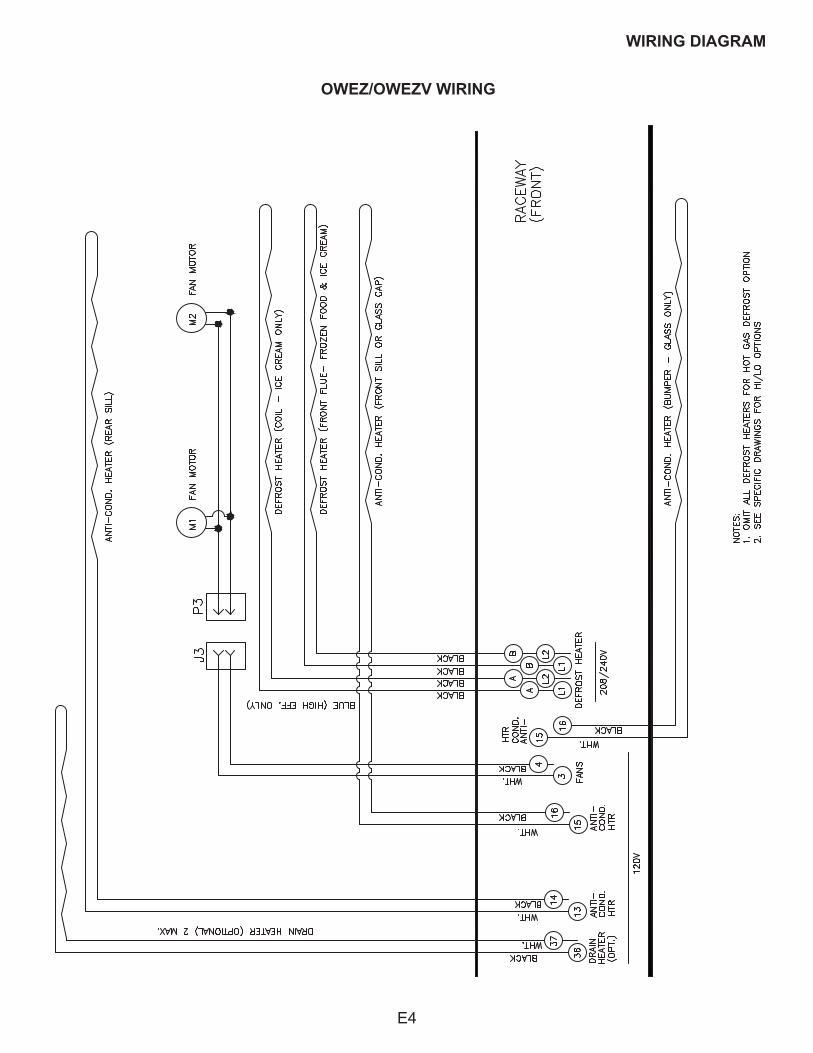
WIRING DIAGRAM
OWEZ/OWEZV WIRING
E4
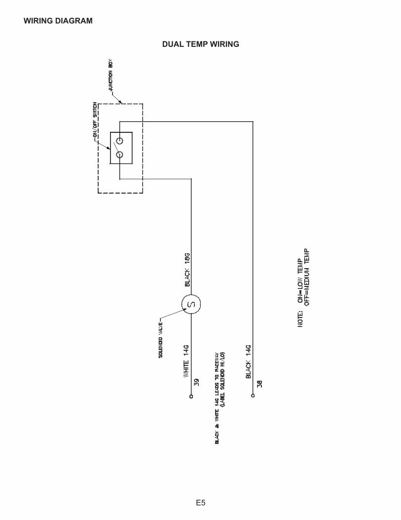
DUAL TEMP WIRING
WIRING DIAGRAM
E5
WIRING DIAGRAM
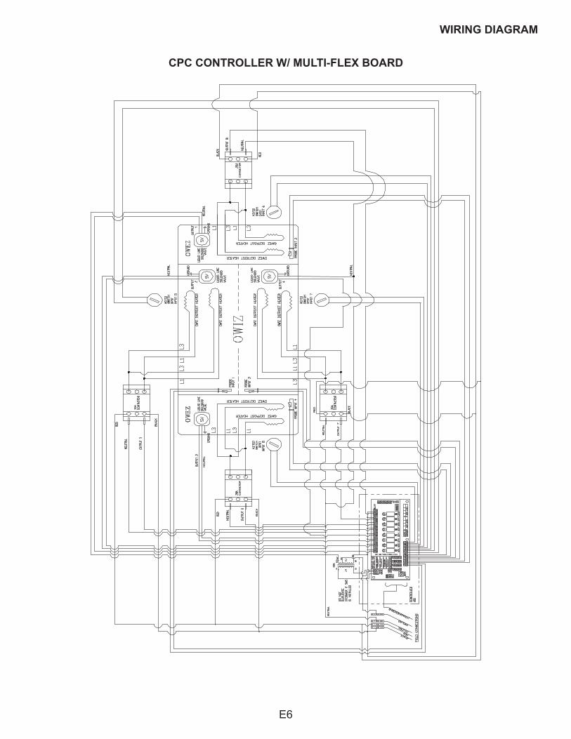
CPC CONTROLLER W/ MULTI-FLEX BOARD
E6
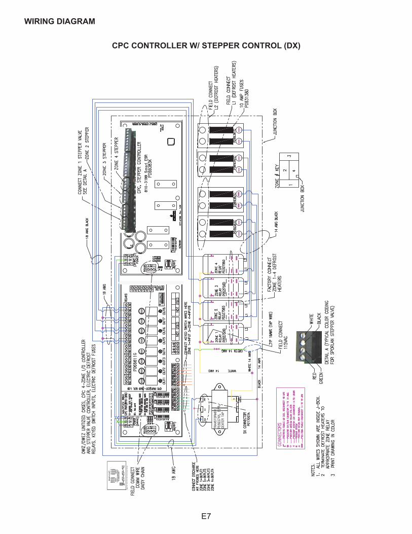
CPC CONTROLLER W/ STEPPER CONTROL (DX)
WIRING DIAGRAM
E7
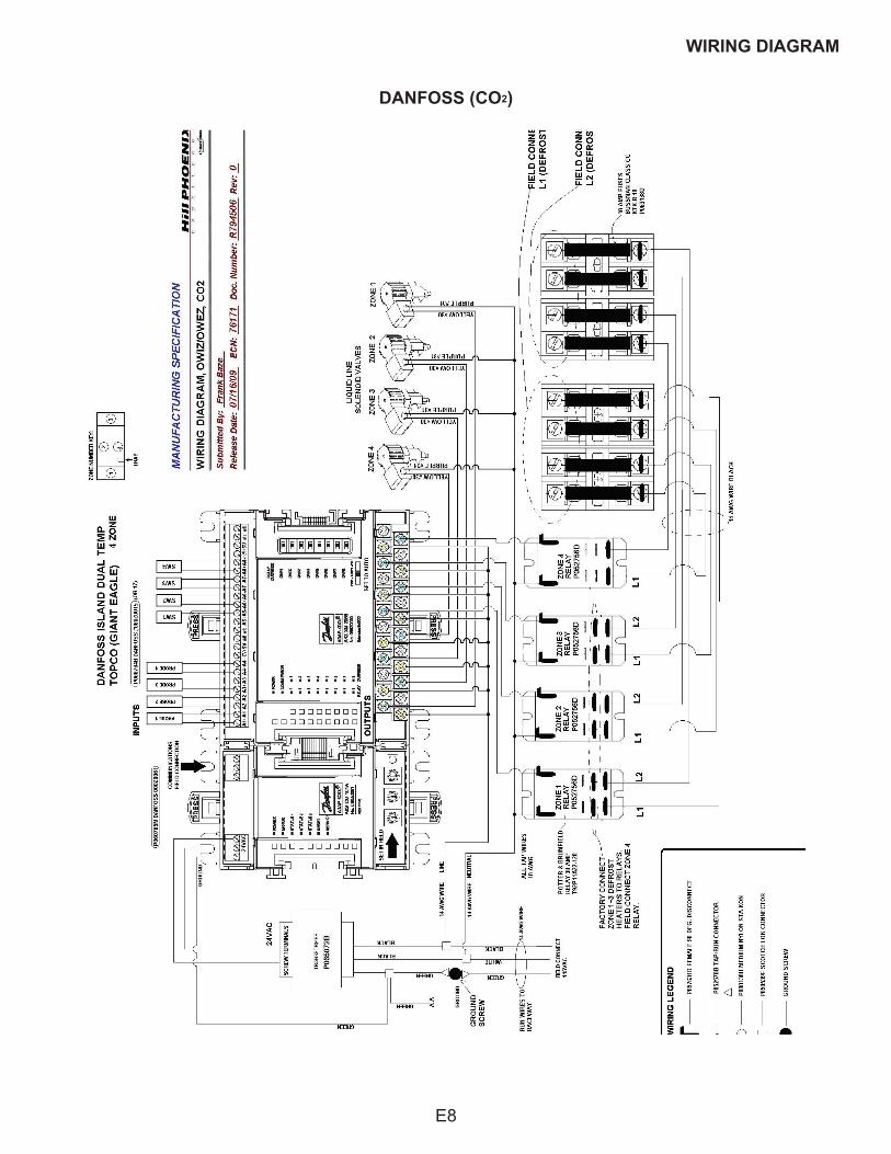
DANFOSS (CO2)
WIRING DIAGRAM
E8
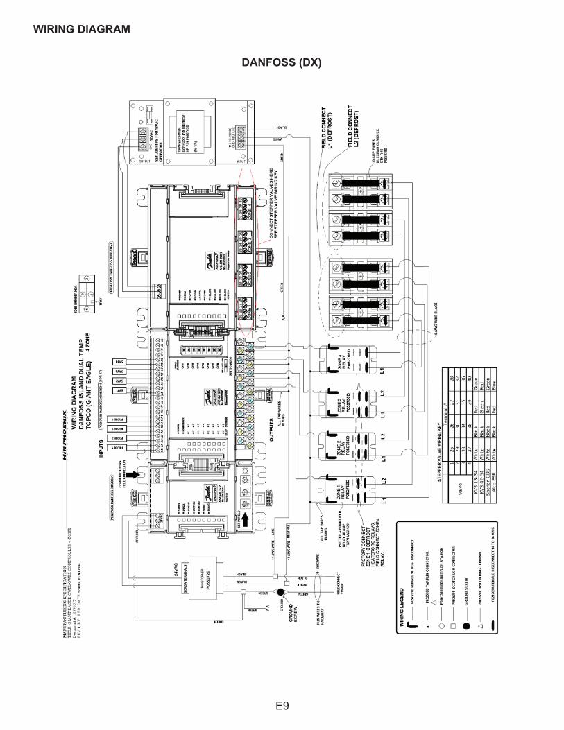
DANFOSS (DX)
WIRING DIAGRAM
E9
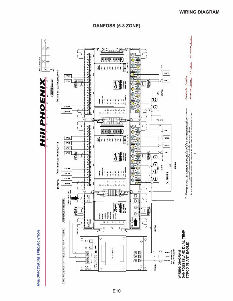
DANFOSS (5-8 ZONE)
WIRING DIAGRAM
E10
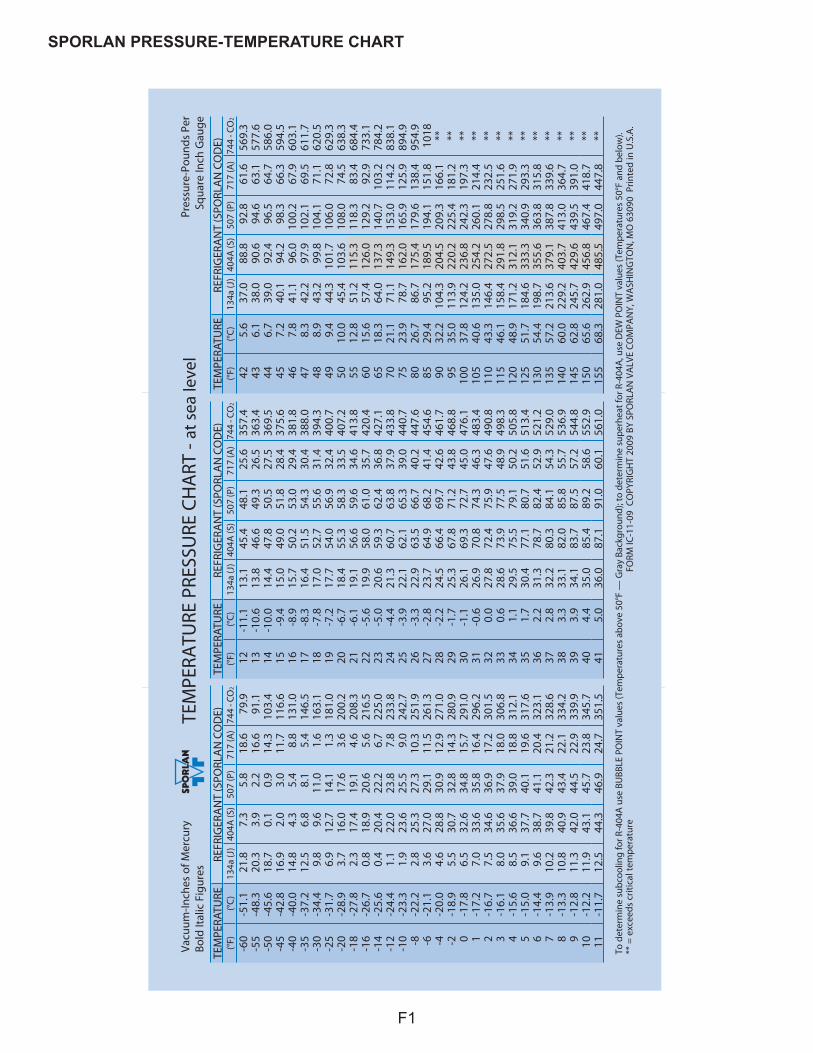
TEM
PERA
TURE
PRE
SSU
RE C
HA
RT -
at s
ea le
vel
To d
eter
min
e su
bcoo
ling
for R
-404
A u
se B
UBB
LE P
OIN
T va
lues
(Tem
pera
ture
s ab
ove
50°F
— G
ray
Back
grou
nd);
to d
eter
min
e su
perh
eat f
or R
-404
A, u
se D
EW P
OIN
T va
lues
(Tem
pera
ture
s 50
°F a
nd b
elow
).**
= e
xcee
ds c
ritic
al te
mpe
ratu
re
Vacu
um-In
ches
of M
ercu
ryBo
ld It
alic
Fig
ures
Pres
sure
-Pou
nds
Per
Squa
re In
ch G
auge
FORM
IC-1
1-09
CO
PYRI
GH
T 20
09 B
Y SP
ORL
AN
VA
LVE
COM
PAN
Y, W
ASH
ING
TON
, MO
630
90 P
rinte
d in
U.S
.A.
TEM
PERA
TURE
REFR
IGER
AN
T (S
PORL
AN
CO
DE)
(°F)
(°C)
134a
(J)
404A
(S)
507
(P)
717
(A)
744
- CO
2
-6
0 -
51.1
21.8
7.3
5.8
18.6
79.9
-5
5 -
48.3
20.3
3.9
2.2
16.6
91.1
-5
0 -
45.6
18.7
0.1
0.9
14.3
103.
4
-45
-42
.816
.92.
03.
011
.711
6.6
-4
0 -
40.0
14.8
4.3
5.4
8.8
131.
0
-35
-37
.212
.56.
88.
15.
414
6.5
-3
0 -
34.4
9.8
9.6
11.0
1.6
163.
1
-25
-31
.76.
912
.714
.11.
318
1.0
-2
0 -
28.9
3.7
16.0
17.6
3.6
200.
2
-18
-27
.82.
317
.419
.14.
620
8.3
-1
6 -
26.7
0.8
18.9
20.6
5.6
216.
5
-14
-25
.60.
420
.422
.26.
722
5.0
-1
2 -
24.4
1.1
22.0
23.8
7.8
233.
8
-10
-23
.31.
923
.625
.59.
024
2.7
-8
-22
.22.
825
.327
.310
.325
1.9
-6
-21
.13.
627
.029
.111
.526
1.3
-4
-20
.04.
628
.830
.912
.927
1.0
-2
-18
.95.
530
.732
.814
.328
0.9
0
-17
.86.
532
.634
.815
.729
1.0
1
-17
.27.
033
.635
.816
.429
6.2
2
-16
.77.
534
.636
.917
.230
1.5
3
-16
.18.
035
.637
.918
.030
6.8
4
-15
.68.
536
.639
.018
.831
2.1
5
-15
.09.
137
.740
.119
.631
7.6
6
-14
.49.
638
.741
.120
.432
3.1
7
-13
.910
.239
.842
.321
.232
8.6
8
-13
.310
.840
.943
.422
.133
4.2
9
-12
.811
.342
.044
.522
.933
9.9
10
-12
.211
.943
.145
.723
.834
5.7
11
-11
.712
.544
.346
.924
.735
1.5
TEM
PERA
TURE
REFR
IGER
AN
T (S
PORL
AN
CO
DE)
(°F)
(°C)
134a
(J)
404A
(S)
507
(P)
717
(A)
744
- CO
2
12
-11
.113
.145
.448
.125
.635
7.4
13
-10
.613
.846
.649
.326
.536
3.4
14
-10
.014
.447
.850
.527
.536
9.5
15
-9
.415
.049
.051
.828
.437
5.6
16
-8
.915
.750
.253
.029
.438
1.8
17
-8
.316
.451
.554
.330
.438
8.0
18
-7
.817
.052
.755
.631
.439
4.3
19
-7
.217
.754
.056
.932
.440
0.7
20
-6
.718
.455
.358
.333
.540
7.2
21
-6
.119
.156
.659
.634
.641
3.8
22
-5
.619
.958
.061
.035
.742
0.4
23
-5
.020
.659
.362
.436
.842
7.1
24
-4
.421
.360
.763
.837
.943
3.8
25
-3
.922
.162
.165
.339
.044
0.7
26
-3
.322
.963
.566
.740
.244
7.6
27
-2
.823
.764
.968
.241
.445
4.6
28
-2
.224
.566
.469
.742
.646
1.7
29
-1
.725
.367
.871
.243
.846
8.8
30
-1
.126
.169
.372
.745
.047
6.1
31
-0
.626
.970
.874
.346
.348
3.4
32
0.
027
.872
.475
.947
.649
0.8
33
0.
628
.673
.977
.548
.949
8.3
34
1.
129
.575
.579
.150
.250
5.8
35
1.
730
.477
.180
.751
.651
3.4
36
2.
231
.378
.782
.452
.952
1.2
37
2.
832
.280
.384
.154
.352
9.0
38
3.
333
.182
.085
.855
.753
6.9
39
3.
934
.183
.787
.557
.254
4.8
40
4.
435
.085
.489
.258
.655
2.9
41
5.
036
.087
.191
.060
.156
1.0
TEM
PERA
TURE
REFR
IGER
AN
T (S
PORL
AN
CO
DE)
(°F)
(°C)
134a
(J)
404A
(S)
507
(P)
717
(A)
744
- CO
2
42
5.
637
.088
.892
.861
.656
9.3
43
6.
138
.090
.694
.663
.157
7.6
44
6.
739
.092
.496
.564
.758
6.0
45
7.
240
.194
.298
.366
.359
4.5
46
7.
841
.196
.010
0.2
67.9
603.
1
47
8.3
42.2
97.9
102.
169
.561
1.7
48
8.
943
.299
.810
4.1
71.1
620.
5
49
9.4
44.3
101.
710
6.0
72.8
629.
3
50
10.0
45.4
103.
610
8.0
74.5
638.
3
55
12.8
51.2
115.
311
8.3
83.4
684.
4
60
15.6
57.4
126.
012
9.2
92.9
733.
1
65
18.3
64.0
137.
314
0.7
103.
278
4.2
70
21
.171
.114
9.3
153.
011
4.2
838.
1
75
23.9
78.7
162.
016
5.9
125.
989
4.9
80
26
.786
.717
5.4
179.
613
8.4
954.
9
85
29.4
95.2
189.
519
4.1
151.
810
18
90
32.2
104.
320
4.5
209.
316
6.1
**
95
35.0
113.
922
0.2
225.
418
1.2
**
100
37
.812
4.2
236.
824
2.3
197.
3**
10
5
40.6
135.
025
4.2
260.
121
4.4
**
110
43
.314
6.4
272.
527
8.8
232.
5**
11
5
46.1
158.
429
1.8
298.
525
1.6
**
120
48
.917
1.2
312.
131
9.2
271.
9**
12
5
51.7
184.
633
3.3
340.
929
3.3
**
130
54
.419
8.7
355.
636
3.8
315.
8**
13
5
57.2
213.
637
9.1
387.
833
9.6
**
140
60
.022
9.2
403.
741
3.0
364.
7**
14
5
62.8
245.
742
9.6
439.
539
1.0
**
150
65
.626
2.9
456.
846
7.4
418.
7**
15
5
68.3
281.
048
5.5
497.
044
7.8
**
SPORLAN PRESSURE-TEMPERATURE CHART
F1
SEISMIC BRACKET INSTALLATION
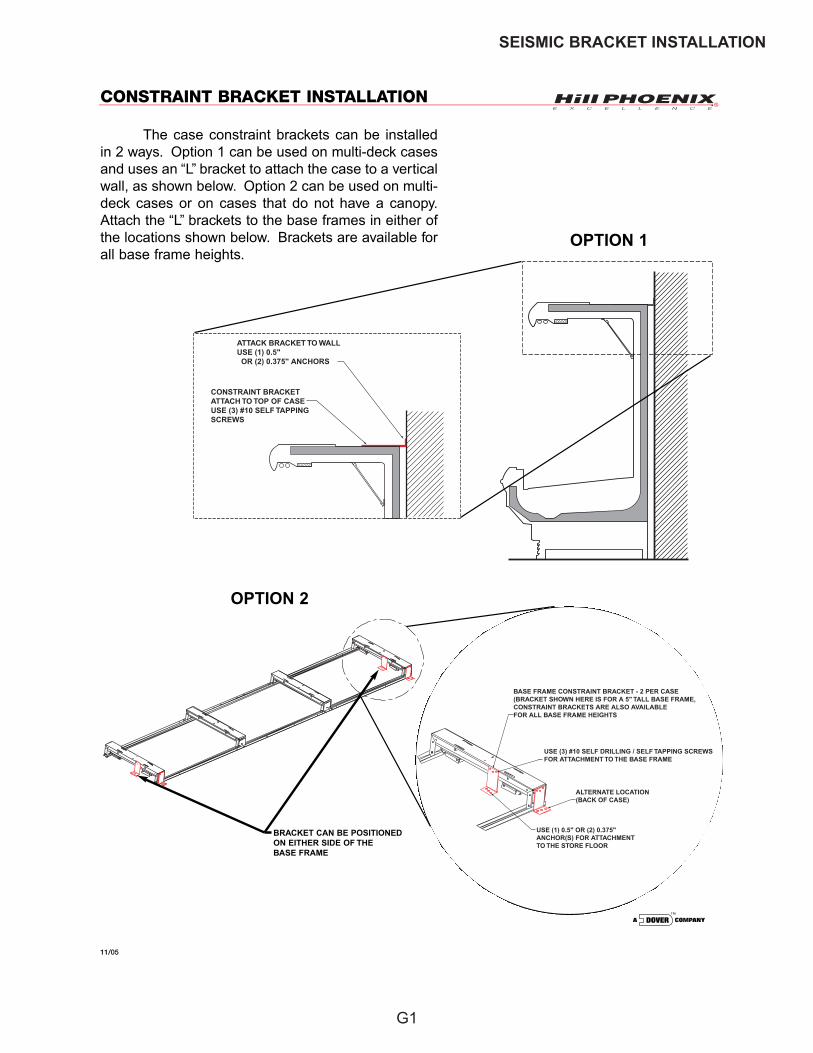
CONSTRAINT BRACKET INSTALLATION
11/05
The case constraint brackets can be installedin 2 ways. Option 1 can be used on multi-deck casesand uses an “L” bracket to attach the case to a verticalwall, as shown below. Option 2 can be used on multi-deck cases or on cases that do not have a canopy.Attach the “L” brackets to the base frames in either ofthe locations shown below. Brackets are available forall base frame heights.
CONSTRAINT BRACKETATTACH TO TOP OF CASEUSE (3) #10 SELF TAPPINGSCREWS
ATTACK BRACKET TO WALLUSE (1) 0.5" OR (2) 0.375" ANCHORS
BASE FRAME CONSTRAINT BRACKET - 2 PER CASE(BRACKET SHOWN HERE IS FOR A 5" TALL BASE FRAME,CONSTRAINT BRACKETS ARE ALSO AVAILABLEFOR ALL BASE FRAME HEIGHTS
USE (3) #10 SELF DRILLING / SELF TAPPING SCREWSFOR ATTACHMENT TO THE BASE FRAME
ALTERNATE LOCATION(BACK OF CASE)
USE (1) 0.5" OR (2) 0.375"ANCHOR(S) FOR ATTACHMENTTO THE STORE FLOOR
OPTION 1
OPTION 2
BRACKET CAN BE POSITIONEDON EITHER SIDE OF THEBASE FRAME
G1
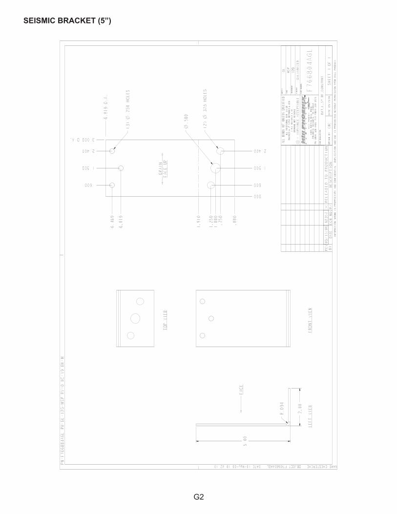
SEISMIC BRACKET (5”)
G2

SEISMIC BRACKET (7”)
G3
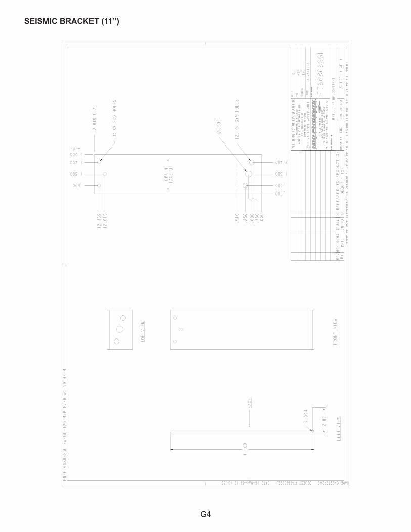
SEISMIC BRACKET (11”)
G4
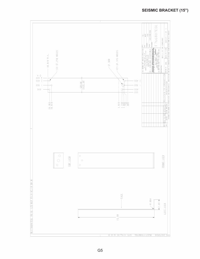
SEISMIC BRACKET (15”)
G5

NOTES

NOTES

NOTES
06/00
WARRANTYHEREINAFTER REFERRED TO AS MANUFACTURER
FOURTEEN MONTH WARRANTY. MANUFACTURER’S PRODUCT IS WARRANTED TO BE FREE FROM DEFECTS IN MATERIAL AND WORKMANSHIP UNDER NORMAL USE AND MAINTENANCE FOR A PERIOD OF FOURTEEN MONTHS FROM THE DATE OF ORIGINAL SHIPMENT. A NEW OR REBUILT PART TO REPLACE ANY DEFECTIVE PART WILL BE PROVIDED WITHOUT CHARGE, PROVIDED THE DEFECTIVE PART IS RETURNED TO MANUFACTURER. THE REPLACEMENT PART ASSUMES THE UNUSED PORTION OF THE WARRANTY.
This warranty does not include labor or other costs incurred for repairing, removing, installing, shipping, servicing, or han-dling of either defective parts or replacement parts.
The fourteen month warranty shall not apply:
1. To any unit or any part thereof which has been subject to accident, alteration, negligence, misuse or abuse, opera-tion on improper voltage, or which has not been operated in accordance with the manufacturer’s recommendation, or if the serial number of the unit has been altered, defaced, or removed.
2. When the unit, or any part thereof, is damaged by fire, flood, or other act of God.
3. Outside the continental United States.
4. To labor cost for replacement of parts, or for freight, shipping expenses, sales tax or upgrading.
5. When the operation is impaired due to improper installation.
6. When installation and startup forms are not properly complete or returned within two weeks after startup.
THIS PLAN DOES NOT COVER CONSEQUENTIAL DAMAGES. Manufacturer shall not be liable under any circumstances for any consequential damages, including loss of profit, additional labor cost, loss of refrigerant or food products, or injury to personnel or property caused by defective material or parts or for any delay in its performance hereunder due to causes beyond its control. The foregoing shall constitute the sole and exclusive remedy of any purchases and the sole and exclu-sive liability of Manufacturer in connection with this product.
The Warranties are Expressly in Lieu of All Other Warranties, Express of Implied and All Other Obligations or Liabilities on Our Part. The Obligation to Repair or Replace Parts or Components Judged to be Defective in Material or Workmanship States Our Entire Liability Whether Based on Tort, Contract or Warranty. We Neither Assume Nor Authorize Any Other Person to Assume for Us Any Other Liability in Connection with Our Product.
MAIL CLAIM TO:
Hill PHOENIXDisplay Merchandisers1925 Ruffin Mill Road
Colonial Heights, VA 238341-800-283-1109
Hill PHOENIXRefrigeration Systems &
Electrical Distribution Products709 Sigman Road
Conyers, GA 30013770-285-3200
WarningMaintenance & Case Care
When cleaning cases the following must be performed PRIOR to cleaning:
To avoid electrical shock, be sure all electric power is turned off before cleaning. In some installations, more than one switch may have to be turned off to complete-ly de-energize the case.
Do not spray cleaning solution or water directly on fan motors or any electrical connections.
All lighting components must be dried off prior to inser-tion and re-energizing the lighting circuit.
Please refer to the Use and Maintenance section of this installation manual.
BDM0803
1925 Ruffin Mill Road, Colonial Heights, VA 23834Due to our commitment to continuous improvement, all specifications are subject to change without notice.
Hill PHOENIX is a Sustaining Member of the American Society of Quality.Visit our web site at www.hillphoenix.com
Tel: 1-800-283-1109