Simultaneous High-Speed OH-PLIF and PIV Measurements...
14
17 th International Symposium on Applications of Laser Techniques to Fluid Mechanics Lisbon, Portugal, 07-10 July, 2014 - 1 - Simultaneous High-Speed OH-PLIF and PIV Measurements to study the Flame Dynamics in an Acoustically Self-Excited Trapped Vortex Combustor Pradip Xavier 1,* , Alexis Vandel 1 , Gilles Godard 1 , Bruno Renou 1,* , Gilles Cabot 1 , Frédéric Grisch 1 , Mourad Boukhalfa 1 , Michel Cazalens 2 1: CORIA-UMR-6614, University of Normandy, Saint Etienne du Rouvray, France 2: Snecma, SAFRAN, Moissy Cramayel, France * correspondent author: [email protected] Abstract Simultaneous Particle Image Velocimetry (PIV), OH Planar Laser Induced Fluorescence (OH-PLIF), acoustic (pressure) and CH* (heat release) measurements were performed to investigate the mechanisms of unstable combustion involved in the stabilization of a turbulent flame above a cavity, in a fully premixed gas turbine Trapped Vortex Combustor. The coupling between the natural flow unsteadiness and the flame structure was achieved by measuring joint velocity-OH images with kHz laser systems. Temporal analysis during one combustion instability cycle shows that thermo-acoustic oscillations induce a tremendous jet instability within the cavity, flapping at the same acoustic frequency. A quantification of turbulence energy levels, with triple velocity decomposition, shows that the pseudo-coherent jet instability due to acoustics is mostly injected via large scale structures. Effects of this aerodynamic instability are clearly visible on the flame structure. The shear strain rate and vorticity prevail, both depending on pressure and heat release fluctuations. 1. Introduction Pollutant emissions reduction has become a major goal in the development of aircraft gas turbines (GT). Conventional combustors are subject to constant improvements but it will not be possible to meet future regulations with actual technologies. For instance, the fixed air split at the outlet compressor guide vane reduces the range of operation, making runs in the low emission zone more difficult (Wulff, 1997). With the knowledge gained on pollutant formation, one solution consists to design the entire combustor architecture from scratch and to combine it with the implementation of new combustion regimes. Several authors have reviewed these potential emerging technologies (Wulff, 1997 ; Lefebvre, 1998) . Lean Premixed Prevaporized (LPP) combustion is one promising solution as it reduces the fuel consumption and avoids high thermal load at the turbine entry, then cutting thermal-NOx emissions. However, use of LPP flames is still challenging as they are much more sensitive to small disturbances and may induce flashback, blow-off or even thermo-acoustic oscillations (Gokulakrishnan, 2008 ; Lieuwen, 2008 ; Candel, 2002). Regarding the combustor architecture, integration of cavity flame holders has been used in scramjet hypersonic combustors for many years (Ben-Yakar, 2001). They have been recently studied for subsonic applications with the Trapped Vortex Combustor (TVC) concept (Hsu, 1998): a recirculation rich flow trapped in a cavity creates a stable pilot flame and continuously ignites a main flow passing above the cavity. The principle of stabilization relies on the migration of hot products and combustion radicals from the cavity to the main flow and could be associated to a Rich burn-Quick mix-Lean burn (RQL) concept. One of the main advantages of the TVC compared to conventional swirl flows lies on the confinement of the pilot flame within a cavity, which remains less affected by sudden changes in the main channel. Thus, wider ranges of operation can be achieved while keeping good flame holding capabilities. Studies on academic experiments demonstrated rather good level of performances regarding Lean Blow-Out (LBO) limits, altitude relight, pollutant emissions and flexibility of operation (Hsu, 1998 ; Hsu, 1995 ; Katta, 1998). More recent works have been carried out to evaluate the concept under realistic operating conditions, especially under high pressure and with liquid fuels (Roquemore, 2001 ; Burrus, 2001).
Transcript of Simultaneous High-Speed OH-PLIF and PIV Measurements...

17th International Symposium on Applications of Laser Techniques to Fluid Mechanics Lisbon, Portugal, 07-10 July, 2014
- 1 -
Simultaneous High-Speed OH-PLIF and PIV Measurements to study the
Flame Dynamics in an Acoustically Self-Excited Trapped Vortex Combustor
Pradip Xavier1,*, Alexis Vandel1, Gilles Godard1, Bruno Renou1,*, Gilles Cabot1,
Frédéric Grisch1, Mourad Boukhalfa1, Michel Cazalens2
1: CORIA-UMR-6614, University of Normandy, Saint Etienne du Rouvray, France
2: Snecma, SAFRAN, Moissy Cramayel, France * correspondent author: [email protected]
Abstract Simultaneous Particle Image Velocimetry (PIV), OH Planar Laser Induced Fluorescence (OH-PLIF), acoustic (pressure) and CH* (heat release) measurements were performed to investigate the mechanisms of unstable combustion involved in the stabilization of a turbulent flame above a cavity, in a fully premixed gas turbine Trapped Vortex Combustor. The coupling between the natural flow unsteadiness and the flame structure was achieved by measuring joint velocity-OH images with kHz laser systems. Temporal analysis during one combustion instability cycle shows that thermo-acoustic oscillations induce a tremendous jet instability within the cavity, flapping at the same acoustic frequency. A quantification of turbulence energy levels, with triple velocity decomposition, shows that the pseudo-coherent jet instability due to acoustics is mostly injected via large scale structures. Effects of this aerodynamic instability are clearly visible on the flame structure. The shear strain rate and vorticity prevail, both depending on pressure and heat release fluctuations. 1. Introduction Pollutant emissions reduction has become a major goal in the development of aircraft gas turbines (GT). Conventional combustors are subject to constant improvements but it will not be possible to meet future regulations with actual technologies. For instance, the fixed air split at the outlet compressor guide vane reduces the range of operation, making runs in the low emission zone more difficult (Wulff, 1997). With the knowledge gained on pollutant formation, one solution consists to design the entire combustor architecture from scratch and to combine it with the implementation of new combustion regimes. Several authors have reviewed these potential emerging technologies (Wulff, 1997 ; Lefebvre, 1998) . Lean Premixed Prevaporized (LPP) combustion is one promising solution as it reduces the fuel consumption and avoids high thermal load at the turbine entry, then cutting thermal-NOx emissions. However, use of LPP flames is still challenging as they are much more sensitive to small disturbances and may induce flashback, blow-off or even thermo-acoustic oscillations (Gokulakrishnan, 2008 ; Lieuwen, 2008 ; Candel, 2002). Regarding the combustor architecture, integration of cavity flame holders has been used in scramjet hypersonic combustors for many years (Ben-Yakar, 2001). They have been recently studied for subsonic applications with the Trapped Vortex Combustor (TVC) concept (Hsu, 1998): a recirculation rich flow trapped in a cavity creates a stable pilot flame and continuously ignites a main flow passing above the cavity. The principle of stabilization relies on the migration of hot products and combustion radicals from the cavity to the main flow and could be associated to a Rich burn-Quick mix-Lean burn (RQL) concept. One of the main advantages of the TVC compared to conventional swirl flows lies on the confinement of the pilot flame within a cavity, which remains less affected by sudden changes in the main channel. Thus, wider ranges of operation can be achieved while keeping good flame holding capabilities. Studies on academic experiments demonstrated rather good level of performances regarding Lean Blow-Out (LBO) limits, altitude relight, pollutant emissions and flexibility of operation (Hsu, 1998 ; Hsu, 1995 ; Katta, 1998). More recent works have been carried out to evaluate the concept under realistic operating conditions, especially under high pressure and with liquid fuels (Roquemore, 2001 ; Burrus, 2001).

17th International Symposium on Applications of Laser Techniques to Fluid Mechanics Lisbon, Portugal, 07-10 July, 2014
- 2 -
Inert flows passing above passive cavities (i.e. no mass injection) have lead to numerous detailed studies in the aerodynamic community (Rockwell, 1979 ; Gharib, 1987). Nevertheless, less fundamental works are referenced for TVC burners, where addition of heat release is associated to an active cavity (i.e. mass injection). In particular, it should be noted that design of such burners may be more complex due to the coupling between the natural flow unsteadiness and heat release, which sometimes leads to strong thermo-acoustic oscillations (Burguburu, 2012). For these reasons, it is paramount to have a fundamental understanding, both from experimentations and computations, about mechanisms involved in a flow passing above a cavity in reactive conditions. Physical understandings will then be used to reduce future design development time. Those precious data can only be acquired with non-intrusive advanced laser diagnostics. As flow and flame dynamics need to be both timely and spatially resolved, use of high-speed laser diagnostics is best suited, which is now possible with recent developments of planar systems with kHz resolution (Böhm, 2009). Several studies have been carried out to investigate unsteady or transient mechanisms in academic turbulent flames or conventional GT burners: local extinction due to vortex-flame interactions in an opposed-jet flame (Böhm, 2009), re-ignition in a jet flame (Steinberg, 2011), flame blowout in a swirl GT (Stohr, 2011), PVC and flashback in LPP swirl flames (Boxx, 2013), flame kernel development in a GT and ignition process in car engines (Boxx, 2013 ; Peterson, 2014). The aim of the present study is to demonstrate and to highlight the capability to implement simultaneous high-speed laser diagnostics on a fully premixed TVC. An unfavorable operating condition, presenting strong thermo-acoustic oscillations, is investigated according to previous works of Xavier et al. (2014). Use of High speed OH-PLIF and PIV, acoustic and CH* measurements are validated, with a focus on determining spatial and temporal measurement limitations. Data processing tools are also introduced and show how dissemination helps on characterizing interactions between the unsteady heat release, the flame structure variations and flow field fluctuations. 2. Experiments 2.1 TVC Burner Experiments were carried out in a fully annular TVC burner, located in a transparent cylindrical combustion chamber (Fig. 1-left). The quartz cylinder, of inner diameter of 80 mm and 200 mm length is made of Herasil to implement laser diagnostics. The latter is surrounded by a second transparent air-cooled chamber to avoid thermal constraints due to high temperature. As effusion walls have not been included in the present setup, the afterbody is made of high temperature stainless steel. Pressure can be increased up to 3 bar, using an adaptive nozzle located at the burner outlet. Dilution air is introduced before the adaptive nozzle to cool down hot gases. More details about the experimental set-up can be found in works done by Taupin et al. (2007). In this study, the burner is fed with air and methane (CH4). All feeding lines can be independently controlled with thermal mass flow controllers. As shown in Fig. 1-right, the CH4/air flow and the Upstream Reactive Flow (URF) in the main channel and in the cavity, respectively, are premixed before entering the chamber. There are 20 rods of 3 mm diameter each which are placed on the upstream cavity edge and are used as flame holders to prevent flash-back phenomena. In the cavity, axisymmetric injections are done with 1 mm aperture slots. The Downstream Cooling Air (DCA) injection creates a double counter-rotative vortices flow topology, according to Roquemore works (2001) and also cools down the afterbody corner. The cavity size is fixed according to works of Burguburu et al. (2012), resulting in a pattern factor of !! / !!"# = 1.19. Fig.1 (Left): Scheme of the experimental setup. (Right): Details of the cavity region in the TVC. !! = 22 mm, !!"#= 18.5 mm

17th International Symposium on Applications of Laser Techniques to Fluid Mechanics Lisbon, Portugal, 07-10 July, 2014
- 3 -
2.2 Operating Conditions The burner is staged between the main channel which surrounds the cavity. Injections of air and fuel in the cavity create several counter rotative vortices and the pilot flame. As this region is rich (i.e. cavity equivalence ratio �! >1), a continuous mass transfer ensures the ignition and the stabilization of a main lean mixture, passing from the left to the right in Fig. 1. Table 1 presents the condition investigated in this study, based on previous works (Burguburu, 2012; Xavier, 2013). The burner boundaries have been choked to suppress any acoustic contributions from the supply and exhaust lines. Indexes m and c represent quantities related to the mainstream and URF cavity flows, respectively. Index glob gives global values, based on the mainstream, URF and DCA flows. The equivalence ratio within the cavity �! is only based on the URF injection.
Parameter Value Velocity [!. !!!] !!! [!. !!!] 21.54 5.0 �! 0.80 !![K] 288
!!! [!. !!!] 0.70 6.0 �! 3.0
!! [!] 288 !!"# [!. !!!] 1.0 3.6 !!"#$ [!. !!!] 23.24
�! 0.83 !!"#$ [bar] 1.7
Tab.1 TVC operating conditions Fig. 2 Mean Velocity vector field colored by the correspondent mean magnitude. For clarity, one vector per two is presented
Figure 2 shows the region of interest investigated in this study as well as the mean velocity field colored by the mean velocity magnitude for the condition presented in Tab. 1. The plane of view is placed between two rods to prevent any reflection. Red arrows show the different jet locations and flow directions within the cavity and in the main channel. Orientations for ! (axial) and ! (radial) velocity components are also presented. Even with mean information, one can see the large interaction between the main channel and the cavity. 2.3 Laser Diagnostics This section will focus on the dual measurement technique apparatus and setup presented in Fig.3. For clarity, the use of each technique is presented separately as well as details about resolution and image treatments. 2.3.1 10 kHz OH-PLIF System Temporal and spatial flame front locations were obtained with a high-speed OH-PLIF dye laser (operating at 10 kHz repetition rate). A Nd-YAG-laser operating at 527 nm was used with an average power of 100 W. The latter pumped a tuneable dye laser (Sirah Credo using Rhodamine 6G in ethanol). At 10 kHz, the resultant output pulse energy was 130 !"/shot in the probe volume. The wavelength was tuned to the !!(5) line of the !!Ʃ! ← !!П! transition of OH (282.655 nm). This theoretical wavelength was adjusted daily using a calibration laminar flame (variation of ±11 pm). The laser beam was coalesced with the PIV beam, using a dichroic mirror and was expanded through a set of fused silica lenses (!! = 1000 mm, !! = - 40 mm) to form a laser sheet of 30 mm height (Fig. 3-left). Fluorescence was collected using an external image intensifier (High Speed IRO, Lavision) mounted with a CMOS-camera (Fastcam SA1) operating with a 512x512 !"#! resolution (21.5 !"#.!!!! magnification ratio). The UV lens (100 mm f/2 B-Halle
17th International Symposium on Applications of Laser Techniques to Fluid Mechanics Lisbon, Portugal, 07-10 July, 2014
- 4 -
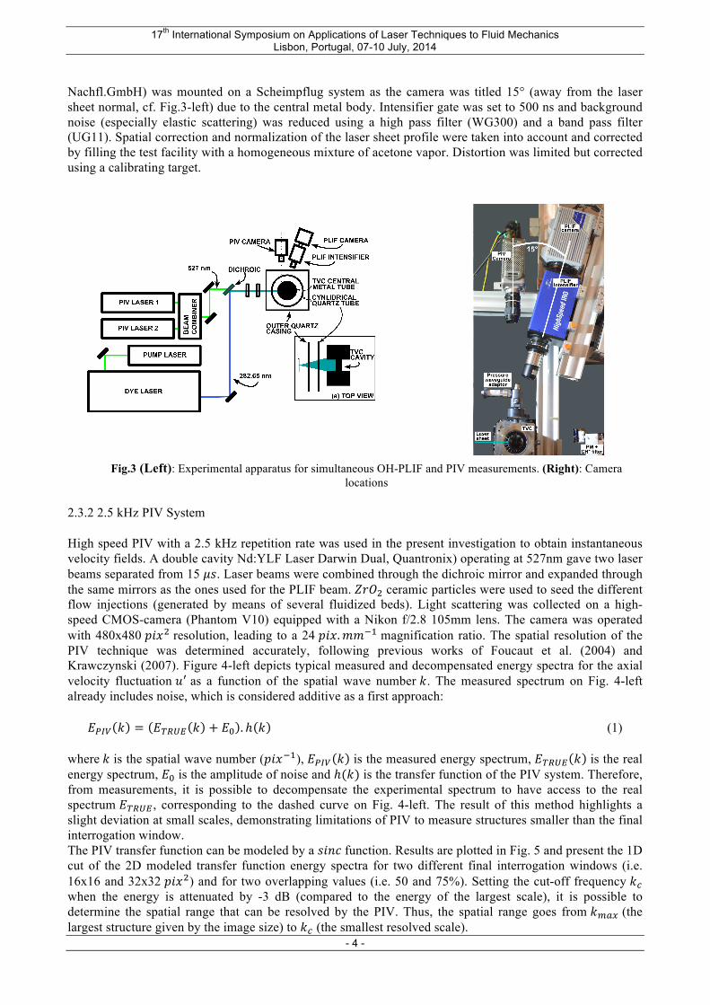
Nachfl.GmbH) was mounted on a Scheimpflug system as the camera was titled 15° (away from the laser sheet normal, cf. Fig.3-left) due to the central metal body. Intensifier gate was set to 500 ns and background noise (especially elastic scattering) was reduced using a high pass filter (WG300) and a band pass filter (UG11). Spatial correction and normalization of the laser sheet profile were taken into account and corrected by filling the test facility with a homogeneous mixture of acetone vapor. Distortion was limited but corrected using a calibrating target.
Fig.3 (Left): Experimental apparatus for simultaneous OH-PLIF and PIV measurements. (Right): Camera locations
2.3.2 2.5 kHz PIV System High speed PIV with a 2.5 kHz repetition rate was used in the present investigation to obtain instantaneous velocity fields. A double cavity Nd:YLF Laser Darwin Dual, Quantronix) operating at 527nm gave two laser beams separated from 15 !". Laser beams were combined through the dichroic mirror and expanded through the same mirrors as the ones used for the PLIF beam. !"#! ceramic particles were used to seed the different flow injections (generated by means of several fluidized beds). Light scattering was collected on a high-speed CMOS-camera (Phantom V10) equipped with a Nikon f/2.8 105mm lens. The camera was operated with 480x480 !"#! resolution, leading to a 24 !"#.!!!! magnification ratio. The spatial resolution of the PIV technique was determined accurately, following previous works of Foucaut et al. (2004) and Krawczynski (2007). Figure 4-left depicts typical measured and decompensated energy spectra for the axial velocity fluctuation !! as a function of the spatial wave number !. The measured spectrum on Fig. 4-left already includes noise, which is considered additive as a first approach:
!!"# ! = !!"#$ ! + !! . ℎ ! (1)
where ! is the spatial wave number (!"#!!), !!"# ! is the measured energy spectrum, !!"#$ ! is the real energy spectrum, !! is the amplitude of noise and ℎ(!) is the transfer function of the PIV system. Therefore, from measurements, it is possible to decompensate the experimental spectrum to have access to the real spectrum !!"#$ , corresponding to the dashed curve on Fig. 4-left. The result of this method highlights a slight deviation at small scales, demonstrating limitations of PIV to measure structures smaller than the final interrogation window. The PIV transfer function can be modeled by a !"#$ function. Results are plotted in Fig. 5 and present the 1D cut of the 2D modeled transfer function energy spectra for two different final interrogation windows (i.e. 16x16 and 32x32 !"#!) and for two overlapping values (i.e. 50 and 75%). Setting the cut-off frequency !! when the energy is attenuated by -3 dB (compared to the energy of the largest scale), it is possible to determine the spatial range that can be resolved by the PIV. Thus, the spatial range goes from !!"# (the largest structure given by the image size) to !! (the smallest resolved scale).

17th International Symposium on Applications of Laser Techniques to Fluid Mechanics Lisbon, Portugal, 07-10 July, 2014
- 5 -
Fig.4 (Left): Measured and decompensated !! energy spectra. Velocity vectors obtained with a final 32x32 !"#! window and a 50% window overlap. (Right): 1D cut of the 2D !"#$! function energy spectra for two different window
overlapping values and two final interrogation windows. Arrows depict the PIV measurement resolved scales.
It is noted that increasing the overlap or decreasing the final interrogation window do not necessary lead to a better resolution since it also increases noise at small scales (Krawczynski, 2007). Eventually, the determined cut-off frequency can be reported on the decompensated spectra. In this study, the PIV image processing was performed with a multipass interrogation window algorithm (dynamic Studio, Dantec) leading to a final 32x32 !"#! interrogation window and a 50% overlap. A coherent filter was applied to correct isolated false vectors so that it gave a final spatial resolution of [2.5mm; 18mm]. 2.3.3 Additional Measurement Techniques A dynamic pressure sensor (10 kHz sampling rate 7061B Kistler) was mounted 280 mm downstream from the cavity region, on a waveguide system. Time lag corrections were taken into account, using an average temperature of 1700! for the burned gases (Merlin, 2012). Acoustics mode detection was done with a one-sided Power Spectral Density (PSD), using the Welch method. Results are given in Sound Pressure Level (SPL, units in !".!"!!) with a frequency resolution of ±5 Hz. Temporal fluctuations of heat release were recorded via CH* emission, with a 10 kHz sampling rate photomultiplier tube (Hamamatsu, 6780-20) amplified and mounted with a band-pass filter (BG12). 2.3.3 Measurements duration The acquisition rates of each measurement are not identical. Table 2 shows the acquisition rates and the number of processed data when coupling all techniques. A parametric study on the amount of images used was performed on the three first statistical moments (mean, standard deviation and skewness), in order to validate that a convergence was reached with the present data.
PLIF PIV Pressure and CH* sensors Rate of aquisition 10 2.5 10
Duration of aquisition 2.18 6.0 6.0 Total number of data 21,829 15,000 60,000
Number of data used for coupling 5,400* 15,000 15,000 Tab. 2 Details of acquisition rates and number of processed data. *: one image per four is taken into account.

17th International Symposium on Applications of Laser Techniques to Fluid Mechanics Lisbon, Portugal, 07-10 July, 2014
- 6 -
3. Image Processing The objective of this study is to understand the interactions between the heat release, the flame structure and the flow field. To accomplish this, automatic in-house image-processing tools were developed, to prevent any parameter modification from one image to another one, and to extract accurate physical quantities from large datasets acquired with kHz systems. 3.1 Flame Front Extraction An image-processing tool was developed to automate the flame front detection. First, spatial correction was performed using a mean laser sheet profile (taken from the acetone fluorescence). More precisely, the following correction was applied to the raw images: !!"## =
!!"#! !!!"#$%! !!!"#$%&! ! !!!"#$%!
(2)
where !denotes the intensity of one pixel and <.> is the ensemble average. Subscript raw, noise and acetone represent the raw image, the background noise (without flame) and the fluorescence with acetone, respectively. The laser sheet energy profile was also adjusted in order to minimize the effect of the correction described in Eq. 2 (especially at the boundaries). Indeed, the mean laser sheet profile, when using a -20 mm cylindrical plano-concave lens, has a peaky Gaussian forms, with important energy variations. Thus, it can lead to measurement biases at the edges of the image. As a result, it was decided to use of a greater cylindrical plano-concave focal length (i.e. - 40 mm) to flatten this profile. The dynamic laser sheet fluctuation and absorption were not implemented in the present experimental configuration. Then, images were smoothed with a 3x3 pixel median filter. An application of a gradient based contour detection filter (Canny) shows that the result contain too many false edges and make the analysis impossible. In order to discriminate the flame-edges from the pixel to pixel noise (due to the intensifier), a Non Linear Diffusive Filter (NLDF) was applied, considering the following diffusion scheme: !!! = ∇ ∙ (!∇!) (3) where ! and ! are the intensity of a pixel and the isotropic local conductivity, respectively. ! is a function of time and space. It can be written in a more precise form: ! |∇! | = !
!! |∇! |²!²
(4)
|∇! | is the local intensity gradient (updated at each time iteration) and ! is a weight coefficient. An
application of the NLDF is depicted in Fig. 5. It clearly demonstrates the non-linear behavior, only smoothing high frequency noise while conserving large scale information with a low attenuation. Note that choosing an anisotropic conductivity (i.e. the flux !∇! is not anymore parallel to the local intensity gradient ∇!) did not enhance the quality of the detection. The implementation of the Canny edge routine on the filtered images (also thinned to single-pixel width contours) lead to good results so that local flame curvature was extracted from the processed images, following:
! = !!!!!! !!!!!
(!!"!!!²)!/! (5)
where ! and ! are the filtered flame edge coordinates with respect to the curvilinear abscissa along the flame fronts (Mokhtarian, 1986).

17th International Symposium on Applications of Laser Techniques to Fluid Mechanics Lisbon, Portugal, 07-10 July, 2014
- 7 -
Fig. 5 Extracted intensity profile of a raw and filtered OH-PLIF image. Original image is in inset. The red dashed line corresponding to the analyzed line.
As shown in Fig. 6-left(a), third order polynomials were fitted to !(!) and !(!) using neighboring points. Number of points and order of the fit were chosen after a sensitivity study, using pre-defined circles generated by hand. For instance, the effect on the number of pixels used for the polynomial fit is depicted on Fig. 6-right. It presents the estimation of different curvature circles, using different neighboring pixels (with 3rd order polynomial fits). The large deviation for small curvatures (i.e. large radii) with few neighboring pixels demonstrates the preponderance of pixel to pixel digitization noise. On the contrary, deviations for large curvatures (i.e. small radii) occur with the use of large pixels, which tends to underestimate small scale features by smoothing them. In his study, it was chosen to use 15 neighboring points (7 on each side) to implement 3rd order polynomials. Constraints were added to suppress contributions from small flame contours (e.g. taken into account only if the length was 1.5 times greater than the number of neighboring points). The maximum curvature resolution was estimated to ± 5!!!!.
Fig. 6 (Left): Flame curvature procedure. (a) Flame front pixel recording and fitting process. (b) Automatic criterion for
the physical curvature sign, where BG are Burned Gases and FG, Fresh Gases. (Right): Sensitivity analysis on the number of pixels used for the polynomial fitting.
Finally, curvatures were physically signed (positive when the flame front is convex towards the fresh gases) curvature was corrected using the dot product sign of the intensity gradient vector ! and the radius of curvature ! (positive when the flame front is convex towards the fresh gases), Fig. 6-right(b). The final routine was capable to run automatically in order to detect several flame fronts in one image, to estimate and physically sign the local curvature distributions.

17th International Symposium on Applications of Laser Techniques to Fluid Mechanics Lisbon, Portugal, 07-10 July, 2014
- 8 -
3.2 Coherent Velocity Field Filtering In the present TVC burner, velocity fluctuations were caused by turbulence (broadband) and pressure oscillations (at nearly one tone). In order to discriminate these two contributions, it was chosen to adopt a triple decomposition, in opposition to the Reynolds decomposition: ! !, !, ! = ! !, ! + ! !, !, ! + !′ !, !, ! (6) where ∙ , ∙, ∙ ′ represent the time average, deterministic and random components of the velocity, respectively, Fig. 7-left (Lieuwen, 2012). Its practical use in turbulent flows is more complicated by variability of the deterministic component with time ("phase jitter") or in amplitude ("non-linear") (Bonnet, 2001). However, in the present investigation, the velocity fluctuation tones were quite accurate, and with no ambiguity, pulsating at the same acoustic tone. The procedure used to automatically implement the triple decomposition is depicted in Fig. 7-right. The temporal evolution of local velocities were recorded and a 2nd order Butterworth low-pass filter (good pass band ripple and short transition band) was applied to this time trace with a cut-off frequency !! slightly higher than the corresponding fundamental acoustic tone, detected from pressure measurements (i.e. !! = !!" + 5Hz.
Fig. 7 Triple decomposition principle. (Left): Definition of variables used. (Right): procedure to implement the triple decomposition, using an acoustic cut-off frequency.
The induced phase-lag !!!! appearing with this filter was estimated at the acoustic frequency, with a transfer function !" as: !!!! = ℑ !" !!" !"#ℎ !" !!" = !!!!
!!!! (7)
Where !.,. is the power spectral density, estimated with the Welch method. 4. Results and Discussion The objective of this study was to illustrate the capability to perform simultaneous PIV/OH-PLIF at kHz rates in a complex TVC, exhibiting strong thermo-acoustic oscillations and, to gain preliminary insights about mechanisms controlling flame stabilization within the burner.

17th International Symposium on Applications of Laser Techniques to Fluid Mechanics Lisbon, Portugal, 07-10 July, 2014
- 9 -
4.1 Characterization of Self-excited Oscillations Figure 8 presents time series of pressure and heat release fluctuations within the burner, which are strongly harmonic but also with non-linear features (i.e. not perfectly sinusoidal). From these global measurements, the coupling between heat release oscillations and pressure fluctuations can be estimated with the space and time averaged Rayleigh criterion: ! = !
!!! ! !! ! !"!!!
! (8) This criterion also corresponds to the phase lag between the two signals !!′!!′ For this condition, !!′!!′ = 72°, which is within +/- 90°. This indicates the possibility of a thermo-acoustic coupling, which leads to an amplication of the instability process, increasing the pressure and heat release fluctuation levels. The corresponding pressure and heat release spectra are presented in Fig. 8 and show large peaks at identical frequencies. Note that the first peak of the heat release, at 50 Hz has no physical meaning and is only due to electromagnetic interferences between the PM amplifier system and the electrical network. The fundamental acoustic frequency occurs at !! = !!" = 122!" and the following spikes are harmonics. Following subsections are dedicated to investigate causes of these coherent fluctuations, especially regarding flow and flame dynamics.
Fig. 8 (Left): Pressure signal (left axis) and CH* radicals intensity (right axis) under self sustained oscillations. (Right): Spectra of pressure and CH* signals. !! = 122Hz, !! = 244Hz, !! =366Hz, !! = 488Hz
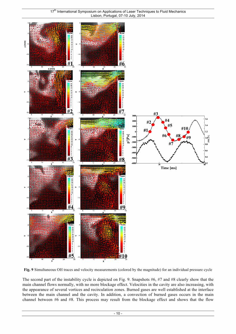
4.2 Description of a Combustion Instability Cycle A sequence of instantaneous OH-PLIF and PIV measurements of the operating condition of Tab. 1 are depicted on Fig. 9 give instantaneous information about velocity vector fields, their corresponding magnitudes and burned gases location (OH signal, in grey scale). The capture corresponding pressure and CH* time series are recalled to report the location of each instantaneous data (numbered red dots) along the instability cycle. When the unsteady pressure is null and the unsteady heat release is almost maximum as in Fig. 9 #1, the flow located within the downstream cavity region is strongly ejected towards the main flow, and can still be observed in Fig. 9 #2 whilst it is decreasing. Effects of this sudden injection are tremendous as it creates a region of low velocities in the main channel. Burned gases location is also altered by this penetration process. The three following snapshots (Fig. 9, #3, #4, #5) highlight a completely different behavior. Indeed, the mass ejection process has disappeared and velocities are quite low within the cavity. On the contrary, the axial main flow velocity ! constantly increases.
17th International Symposium on Applications of Laser Techniques to Fluid Mechanics Lisbon, Portugal, 07-10 July, 2014
- 10 -
Fig. 9 Simultaneous OH traces and velocity measurements (colored by the magnitude) for an individual pressure cycle
The second part of the instability cycle is depicted on Fig. 9. Snapshots #6, #7 and #8 clearly show that the main channel flows normally, with no more blockage effect. Velocities in the cavity are also increasing, with the appearance of several vortices and recirculation zones. Burned gases are well established at the interface between the main channel and the cavity. In addition, a convection of burned gases occurs in the main channel between #6 and #8. This process may result from the blockage effect and shows that the flow

17th International Symposium on Applications of Laser Techniques to Fluid Mechanics Lisbon, Portugal, 07-10 July, 2014
- 11 -
velocity is larger than the local flame speed. When the pressure increases (snapshot #9 and #10), the ejection disturbance starts again to block the main flow. It can be concluded from this sequence that strong ejection instability, located in the downstream part of the cavity affects both low and burned gases location. It is noted that this instability may be due to the DCA jet, flapping between the cavity and the main channel. Origins and effects of this "jet flapping" instability are investigated in the following sections. 4.3 Effects of Thermo-Acoustic Oscillations on the Flow Field In order to quantify the flow response to the jet flapping instability, a frequential investigation is done with PIV images. Figures 10-Left and 10-Right present the Fast Fourier Transform (FFT) of both axial and radial velocity fluctuations, respectively !! and !! (based on Reynolds decomposition). FFTs are based on two distinct zones A and C, in the main channel and in the cavity, respectively (cf. Fig. 1-right).
Fig. 10 (Left): FFT magnitude of u’ and v’ components in zone A. (Right): FFT magnitude of u’ and v’ component in
zone C One can see that the acoustic tones are retrieved on the velocities time series, whatever the zone considered. In zone A, the coherent axial oscillation points out the strength of the jet ejection on the main channel disturbance. FFTs in zone C (cavity) demonstrate the influence of thermo-acoustic oscillations on the cavity region. This great flow sensitivity leads to a strong pulsed combustion regime.
Fig. 11 Comparison between total energy spectra ! !, !, ! + !′ !, !, ! or ! !, !, ! + !′ !, !, ! and filtered ones !′ !, !, ! or !′ !, !, ! , using the triple decomposition. !!" corresponds to the energy spectra ratio of the axial
component ! in the radial direction !. The pseudo-coherent flow energy oscillation demonstrated in Figs. 10-left and right can be compared to the turbulence contribution (using the triple decomposition). Results are shown in Fig. 11. It compares the ratio

17th International Symposium on Applications of Laser Techniques to Fluid Mechanics Lisbon, Portugal, 07-10 July, 2014
- 12 -
of energy spectra of total velocity fluctuations (! !, !, ! + !′ !, !, ! ) and filtered ones ( !′ !, !, ! ). As the flow field is anisotropic, four 1D-cuts of 2D-energy spectra of both axial and radial velocities are represented, according to two spatial wave numbers (collinear with velocity vectors). One should note the similar trend observed whatever the direction and the velocity component. Purely acoustics contribution has an isotropic and global effect on the burner, being more preponderant for large scales, where the contribution is up to 3 times larger. Rapidly, at fine scales, the level of this contribution drops to 1.2 to remain constant. This value is not important compared to the pulsed combustion regime and should be explained by a continuous energy dissipation through the energy cascade. 4.4 Influence of Aerodynamic Instabilities on the Flame Front Structure Due to the low resolution along the flame front, investigation of the flow/flame interactions were done separately, by calculating instantaneous flow properties with PIV data and superimposing them with the flame front location.
Fig. 12 Contribution of vorticity and shear strain . For clarity, one vector per two is shown. Snapshots are conditioned
according to the pressure signal. Results in Fig. 12 present different instantaneous flame front contours overlaid by instantaneous 2D-vorticity field Ω! and shear strain∇!!, all conditioned by the pressure instability cycle. It is interesting to note that the flow interacts differently according to the position in the instability cycle. Figs. 12, � = 0° and 290° show two large counter rotative vortices around the cavity jet. These vortices stretch the flame front. On the contrary, flame fronts are submitted to the shear strain flow in Figs. 12, � = 170° and 230°. The latter effect contributes to the heat release increase and may pilot mixing and ignition processes in the burner. The measurements flame curvatures did not lead to interesting conclusions and may put in evidence the limitations of the OH radical to be a accurate flame front marker. 5. Conclusions Simultaneous kHz framerate PIV and OH PLIF on a fully premixed Trapped Vortex Combustor exhibiting thermo-acoustic oscillations revealed a strong aerodynamic jet instability in the cavity recirculation zone, affecting turbulence levels, burner staging and flame stabilization. Several works have pointed out advantages of this new stabilization technique, leading to wider ranges of operations, reduced !"! emissions and better relight capabilities. This novel architecture has a great potential as an alternative to conventional swirl stabilized combustors but many efforts must be done to determine universal simple and robust sizing rules. As inert flows above cavities are naturally unsteady, addition of heat release may also affect the flame stabilization process. It was then decided to investigate an unfavorable condition, measuring jointly time and spatial resolved velocity and OH concentrations with help of kHz frame rate laser diagnostics. In order to treat the large amount of data collected, several image-processing routines were developed to automatically extract flame contours (based on OH gradients), estimate local flame curvatures, and quantify energetic contributions of deterministic and random velocity fluctuations. Instantaneous analysis of a combustion instability cycle put into evidence a jet instability in the cavity, flapping at the same acoustic frequency. This aerodynamic instability blocks the main flow when it expands into the main channel. The related pseudo-coherent fluctuation injects energy via large scale structures but

17th International Symposium on Applications of Laser Techniques to Fluid Mechanics Lisbon, Portugal, 07-10 July, 2014
- 13 -
also affect the whole energy cascade. It was also shown that the flow influences the flame front through vorticity and shear strain rate, depending on the instability cycle position. Further investigations may be done with another flame tracer (i.e. CH) as OH concentrations in a large recirculation zones reduces the flame front tracking accuracy. An access to the mixture fraction field should also help on understanding mixing and chemical effects. Eventually, a more detailed acoustic analysis will be performed in a future work to understand causes of the different acoustic tones and their relations to the geometry. Acknowledgments The research leading to these results has received funding from the European Community’s Seventh Framework Programme (FP7/2007-2013) under GrantAgreement n◦ ACP0-GA-2011-265586. The authors would like to thank Dr. Benoît Barviau (lecturer at University of Rouen) and Dr. Julien Apeloig (post-doc at INSA of Rouen) for their fruitful discussions and comments. References Ben-Yakar A, Hanson R.K. (2001) Cavity flame-holders for ignition and flame stabilization in scramjets: an overview. Journal of Propulsion and Power, 17(4):869–877.
Bohm B, Geyer D, Gregor M.A et al (2013). Advanced Laser Diagnostics for Understanding Turbulent Combustion and Model Validation. In: Flow and Combustion in Advanced Gas Turbine Combustors, Springer, volume 1581, chapter 4, pp 93–160.
Bohm B, Heeger C, Boxx I et al (2009). Time-resolved conditional flow field statistics in extinguishing turbulent opposed jet flames using simultaneous high speed PIV/OH-PLIF. Proceedings of the Combustion Institute, 32(2):1647–1654.
Bonnet J.P and Delville J. (2001). Review of coherent structures in turbulent free shear flows and their possible influence on computational methods. Flow, Turbulence and Combustion, 66:333–353.
Boxx I, Carter C, Stohr M et al (2013). Study of the mechanisms for flame stabilization in gas turbine model combustors using kHz laser diagnostics. Experiments in Fluids, 54(5):1–17.
Boxx I, Carter C, Stohr M et al (2010). Temporally resolved planar measurements of transient phenomena in a partially premixed swirl flame in a gas turbine model combustor. Combustion and Flame, 157(8):1510–1525.
Burguburu J, Cabot G, Renou B et al (2012). Flame stabilization by hot products gases recirculation in a Trapped Vortex Combustor. In Proceedings of the ASME, pp GT2012–68451, Copenhagen, Denmark, June 11-15.
Burrus D.L, Johnson A.W., Roquemore W.M. et al (2001). Performance assessment of a prototype Trapped Vortex Combustor concept for gas turbine applications. In ASME Turbo Expo, pages GT2001–0087, Atlanta, USA, July 16-19.
Candel S (2002). Combustion dynamics and control: Progress and challenges. volume 29, pp 1–28. Proceedings of the Combustion Institute.
Foucaut J.M, Carlier J, Stanislas M (2004) PIV optimization for the study of turbulent flow using spectral analysis. Meas. Sci. Technol, 8:1427–1440.
Gharib M, Roshko A (1987) The effect of flow oscillations on cavity drag. J. Fluid Mech., 177(10):510–530.
Gokulakrishnan P et al (2008). A novel low-NOx lean, premixed, and prevaporized combustion system for liquid fuels. Journal of engineering for gas turbines and power, 130(5):051501.
Hsu K.Y, Goss L.P, Trump D.D et al (1998). Characteristics of a Trapped Vortex Combustor. Journal of Propulsion and Power, 14(1):57–65.

17th International Symposium on Applications of Laser Techniques to Fluid Mechanics Lisbon, Portugal, 07-10 July, 2014
- 14 -
Hsu K.Y, Goss L.P, Trump D.D et al (1995). Performance of a Trapped Vortex Combustor. In 33rd AIAA Aerospace Sciences Meeting and Exhibit, pages 95–0810, Reno, NV, USA, January 9-12. Katta V.R, Roquemore W.M (1998). Numerical studies on Trapped Vortex Combustor for stable combustion. Journal of engineering for gas turbines and power, 120(1):60–68.
Krawczynski J.F (2007). La structure du champ de vitesse dans un réacteur à jets opposés. Caractérisation du mélange turbulent. PhD thesis, University of Rouen.
Lefebvre A.H (1998). Gas Turbine Combustion. CRC Press.
Lieuwen T, McDonnell V, Petersen E et al (2008). Fuel flexibility influences on premixed combustor blowout, flashback, autoignition, and stability. Journal of engineering for gas turbines and power, 130(1):11506.
Lieuwen T (2012) Unsteady combustor physics. Cambridge University Press.
Merlin C (2012) Simulation numérique de la combustion turbulente: Méthode de frontières immergées pour les écoulements compressibles, application à la combustion en aval d’une cavité. PhD thesis, INSA of Rouen, France.
Mokhtarian, Macworth A (1986) Scale-based description and recognition of planar curves and two-dimensional shapes. Pattern Analysis and Machine Intelligence, IEEE Transactions, (1):34–43.
Peterson B, Reuss D.L, Sick V (2014). On the ignition and flame development in a spray-guided direct-injection spark-ignition engine. Combustion and Flame, 161(1):240–255.
Rockwell D, Knisely C (1979) The organized nature of flow impingement upon a corner. J. Fluid Mech., 93(03):413–432.
Roquemore W.M et al (2001) Trapped Vortex Combustor concept for gas turbine engines. In 39th AIAA Aerospace Sciences Meeting and Exhibit, pages 2001–0489, Reno, NV, USA, January 8-11.
Steinberg A.M, Boxx I et al. (2011) Experimental study of flame-hole re-ignition mechanisms in a turbulent non-premixed jet flame using sustained multi-kHz PIV and crossed-plane OH PLIF. Proceedings of the Combustion Institute, 33(1):1663–1672.
Stohr M, Boxx I, Carter C et al (2011). Dynamics of lean blowout of a swirl stabilized flame in a gas turbine model combustor. Proceedings of the Combustion Institute, 33(2):2953–2960.
Taupin B et al (2007). Experimental study of stability, structure and CH* chemiluminescence in a pressurized lean premixed methane turbulent flame. Combustion Science and Technology, 179:117–136.
Wulff A, Hourmouziadis J (1997) Technology review of aeroengine pollutant emissions. Aerospace Science and Technology, 8:557–572.
Xavier P et al (2014) Analysis of the flame structure in a Trapped Vortex Combustor using low and high-speed OH-PLIF. In Proceedings of the ASME, pp GT2014–25207, Dusseldorf, Germany, June 16-20.
Xavier P et al (2013). Towards Low-NOx operation in a complex burner. Optimization of an annular Trapped Vortex combustor. In Proceedings of the ASME, pp GT2013–94704, San Antonio, USA, June 3-7.

![Simultaneous OH-PLIF and schlieren imaging of flame ...ltces.dem.ist.utl.pt/lxlaser/lxlaser2016/finalworks2016/papers/03.1_1... · Dorofeev [4] summarizes the current state-of-knowledge](https://static.fdocuments.us/doc/165x107/60651c784366af40bc00320a/simultaneous-oh-plif-and-schlieren-imaging-of-flame-ltcesdemistutlptlxlaserlxlaser2016finalworks2016papers0311.jpg)