
Simulation study of tremor suppression and …/67531/metadc149647/m2/1/high... · Simulation study...
39
APPROVED: Xun Yu, Major Professor Jiangtao Cheng, Committee Member Yan Wan, Committee Member Yong Tao, Chair of the Department of Mechanical and Energy Engineering Costas Tsatsoulis, Dean of the College of Engineering Mark Wardell, Dean of the Toulouse Graduate School SIMULATION STUDY OF TREMOR SUPPRESSION AND EXPERIMENT OF ENERGY HARVESTING WITH PIEZOELECTRIC MATERIALS Jianqiang Ou Thesis Prepared for the Degree of MASTER OF SCIENCE UNIVERSITY OF NORTH TEXAS August 2012
-
Upload
hoangthuan -
Category
Documents
-
view
213 -
download
0
Transcript of Simulation study of tremor suppression and …/67531/metadc149647/m2/1/high... · Simulation study...
APPROVED: Xun Yu, Major Professor Jiangtao Cheng, Committee Member Yan Wan, Committee Member Yong Tao, Chair of the Department of
Mechanical and Energy Engineering Costas Tsatsoulis, Dean of the College of
Engineering Mark Wardell, Dean of the Toulouse
Graduate School
SIMULATION STUDY OF TREMOR SUPPRESSION AND EXPERIMENT OF
ENERGY HARVESTING WITH PIEZOELECTRIC MATERIALS
Jianqiang Ou
Thesis Prepared for the Degree of
MASTER OF SCIENCE
UNIVERSITY OF NORTH TEXAS
August 2012

Ou, Jianqiang. Simulation study of tremor suppression and experiment of energy
harvesting with piezoelectric materials. Master of Science (Mechanical and Energy
Engineering), August 2012, 31 pp., 1 tables, 15 illustrations, references, 20 titles.
The objective of this research is to develop a wearable device that could harvest
waste mechanical energy of the human hand movement and utilize this energy to
suppress wrist tremors.
Piezoelectric material is used to measure the hand movement signals, and the
signal of wrist tremor is filtered to be utilized to suppress the tremor. In order to conduct
the experiment of energy harvesting and tremor suppression, an experimental rig was
fabricated. Two types of piezoelectric materials, PVDF (polyvinylidene fluoride) films
and MFC (macro fiber composite) films, are used to harvest mechanical energy and
used as actuators to suppress hand tremors. However, due to some shortages of the
materials, these two types of materials are not used as actuators to suppress the wrist
tremors. Thus, we use Matlab Simulink to simulate the tremor suppression with AVC
(active vibration control) algorithm.

ii
Copyright 2012
by
Jianqiang Ou

iii
ACKNOWLEDGMENTS
I would like to thank my parents, my sisters and my friends for their support and
encouragement mentally.
I would like to extend my sincere gratitude and appreciation to my adviser, Dr. Xun
Yu, for his support, understanding, constructive guidance. It is my privilege to have the
opportunity to work with Dr Yu, It was his inspiration, integrity and understanding that
got many things this far.
I also want to give my thanks to Mr. Peng Li in the lab for his unconditional help
when I was in University of Minnesota, Duluth at 2011 spring.
My sincere appreciation also extends to the members of my master thesis
committee, Dr. Jiangtao Cheng and Dr. Yan Wan for their committed service and
support, their ideas, and suggestions that helped improve my work significantly.
Last but not the least; I want to express my thanks to all other faculty members
and classmates in the Mechanical and Energy Engineering Department for their
assistance and excellent lectures for my knowledge and life.

iv
TABLE OF CONTENTS
Page
ACKNOWLEDGMENTS .................................................................................................. iii
LIST OF TABLES ............................................................................................................ vi
LIST OF FIGURES ......................................................................................................... vii
CHAPTER 1 INTRODUCTION ........................................................................................ 1
1.1 Motivation of the Thesis ............................................................................. 1
1.2 Objective .................................................................................................... 2
1.3 Thesis Outline ............................................................................................ 2
CHAPTER 2 LITERATURE REVIEW ............................................................................. 3
2.1 Hand Tremor .............................................................................................. 3
2.3.1 Overview of Hand Tremor ............................................................... 3
2.3.2 Treatment for Hand Tremor ............................................................ 4
2.2 Piezoelectric Energy Harvesting ................................................................ 4
2.3 Active Vibration Control ............................................................................. 5
2.3.3 Feedback Control ........................................................................... 6
2.3.4 Feedforward Control ....................................................................... 7
CHAPTER 3 DESIGN AND MANUFACTURE OF THE EXPERIMENTAL RIG ............. 8
3.1 Problem Identification ................................................................................. 8
3.2 Selection of Linear Motor ............................................................................. 8
3.3 The Detail Dimension of the Experimental Rig ........................................ 10
CHAPTER 4 THE EXPERIMENT SETUP AND RESULT ANALYSIS .......................... 12
4.1 Experiment Setup for the Energy Harvesting ........................................... 12
4.2 Result and Analysis ................................................................................. 14
CHAPTER 5 SIMULATION OF TREMOR SUPPRESSION ......................................... 15
5.1 Active Vibration Algorithm ......................................................................... 15
5.2 Computer Simulation ............................................................................... 17
5.3 The Analysis of the Result ....................................................................... 19
5.3.1 First Set of Tremor Signal ............................................................. 19

v
5.3.2 Second Set of Tremor Signal ........................................................ 22
5.3.3 Third Set of Tremor Signal ............................................................ 25
CHAPTER 6 CONCLUSIONS AND FUTURE WORK .................................................. 29
6.1 Conclusions ............................................................................................. 29
6.2 Future Work ............................................................................................. 29
REFERENCES .............................................................................................................. 30

vi
LIST OF TABLES
Page
1. Energy harvesting result ..................................................................................... 14

vii
LIST OF FIGURES
Page
Figure 1 Principle of feedback control ............................................................................ 7
Figure 2 Principle of feedforward control ........................................................................ 7
Figure 3 The performance of the linear actuator 43M4Z ................................................ 9
Figure 4 The dimension detail of the experimental rig .................................................. 10
Figure 5 The experimental rig ...................................................................................... 11
Figure 6 The experimental setup of energy harvesting ................................................ 13
Figure 7 The energy harvesting glove with MFC and PVDF ........................................ 13
Figure 8 Block diagram of ANC/AVC system with FXLMS algorithm .......................... 16
Figure 9 Diagram of the simulation model in Simulink.................................................. 18
Figure 10 The simulation result of the first set of tremor signal .................................... 21
Figure 11 The comparison of the spectra in the first set................................................ 21
Figure 12 The simulation result of the second set of tremor signal .............................. 24
Figure 13 The comparison of the spectra in the second set ......................................... 24
Figure 14 The simulation result of the third set of tremor signal ................................... 27
Figure 15 The comparison of the spectra in the third set ............................................. 27

1
CHAPTER 1
INTRODUCTION
The objective of this research is to develop a wearable device that could harvest
waste mechanical energy of the human hand movement and utilize this energy to
suppress wrist tremors. Since the frequency spectra of wrist tremors is different from the
one of voluntary hand movements, piezoelectric material is used to measure the hand
movement signals, and the signal of wrist tremor is filtered to be utilized to suppress the
tremor. In order to conduct the experiment of energy harvesting and tremor suppression,
I fabricate an experimental rig, which is driven by a linear stepper motor. Two types of
piezoelectric materials, PVDF (polyvinylidene fluoride) films and MFC (macro fiber
composite) films, are used to harvest mechanical energy and used as actuators to
suppress hand tremors. However, due to some shortages of the materials, these two
types of materials were not used as actuators to suppress the wrist tremors. I analyze
the reason in Chapter 5.
1.1 Motivation of the Thesis
Most of the people having Parkinsonism suffer from tremor or involuntary disorder
movement. They have to face difficulties in their daily life because of the hand tremor.
There are different methods to alleviate the symptoms of human hand tremor.
However, most treatment methods accompany with different negative side effects. For
instance, surgical therapy may comes with a high risk to a patient life because it has to
operate on the brain, and drug therapy may have a negative long term side effect. Thus,

2
this research is attempted to develop a non-invasive system that could suppress the
human hand tremors.
1.2 Objective
The key objectives of this thesis are:
• To simulate the tremor suppression algorithm by using the Matlab Simuliink.
• To fabricate the experimental rig to mimic the human hand movement and the involuntary tremor.
• To conduct the energy harvesting experiment, and to evaluate the energy harvesting performance of different piezoelectric materials.
• To analyze the reasons why the current materials are not good enough to apply in the final device.
• To discuss some possible work in the future.
1.3 Thesis Outline
Chapter 2 begins with a brief review of selected literature pertaining to energy
harvesting and active vibration control.
Chapter 3 talks about the design and manufacture of the experimental rig.
Chapter 4 describes the experiment results of the energy harvesting with the
experimental rig.
Chapter 5 describes the modeling and simulation of tremors suppression with
adaptive control and discusses the reason why MFC could not be used as actuators for
the tremor suppression glove.
Finally, the main conclusions and some recommendations for possible future
extension of this work are presented in chapter 6.

3
CHAPTER 2
LITERATURE REVIEW
This chapter gives a brief overview of useful literature in hand tremor, energy
harvesting using piezoelectric materials, and active noise/vibration control technology.
2.1 Hand Tremor
2.3.1 Overview of Hand Tremor
Tremor is defined as an involuntary, approximately rhythmic, and roughly
sinusoidal movement [1]. It occurs in many neurological disorders including essential
tremor (ET) and Parkinson’s disease (PD) [2].
A lot of research on hand tremor has been done mainly to discover its movement
pattern by analyzing its amplitude and spectra. In fact, every person has his/her own
tremor [3] but with different level of amplitude and spectra. Thus, even healthy people
have a slight tremor, but people with Parkinson’s disease suffer from a more serious
tremor, so that they could not even control their movements [4]. As a result, it is hard for
those patients to deal with their daily life. Since the frequency between human tremor
and voluntary movement are different, it is essential to discover the frequency range of
the human tremor and voluntary movement.
There are two types of tremor happens on the PD patients: (1) resting tremor, and
(2) postural tremor. Resting tremor is such kind of tremor which happens when the
patient stays relaxed and the limbs are fully supported [5]. Postural tremor happens
while the patient is voluntarily maintaining a position against gravity [6]. For these two
kinds of tremor, the displacement amplitude is in the range of ±5mm [7], [8], [9]. In

4
addition, the frequency tends to vary inversely with the amplitude of tremor. In other
word, the frequency will increase while the amplitude of tremor decreases [10]. From
the literature review, it is found that the frequency range of these two kinds of tremor is
from 3 to 12 Hz [5] [11], [12].
2.3.2 Treatment for Hand Tremor
Nowadays, there are still no effective ways to totally cure human tremor, but there
are different treatments that can alleviate the symptoms of the patients. Drug therapies
and surgery are the two mainstream of current medical treatment.
Prescribed drug such as Alprazolam and Levodopa are typically used for alleviate
the symptoms of PD patients, however they all have different kinds of serious side
effects and have to be used carefully [13].
On the other hand, surgery is the alternative method for PD patient. Since all of
these surgeries have to operate on human brain, it is very risky.
2.2 Piezoelectric Energy Harvesting
Energy harvested from wasted or unused mechanical power has become a more
and more popular topic. One of these kinds of wasted power is generated from human
activity.
The field of energy harvesting by utilizing piezoelectric materials has been
researched greatly over past decades. Most research on this subject tried to maximize
the energy harvesting ability of these piezoelectric materials. Usually, a monolithic
piezoelectric material with a traditional electrode pattern and poled through its thickness

5
is used for power harvesting [14]. However, a lot of research has been conducted on
developing a broad range of piezoelectric composite sensor/actuators, some products
derived from this research have their own operational advantages and characteristics.
The majority of these products are applied in the field of control and vibration
suppression applications [14], and they also have great potential for use in power-
harvesting systems.
There are three kinds of piezoelectric materials, which are most frequently used.
The first one are polymers (polyvinylidene fluoride, PVDF), and the second one are
ceramics (lead zirconate titanate, PZT). The polymer materials are soft and flexible;
however have lower dielectric and piezoelectric properties than ceramics. Conventional
piezoelectric ceramic materials are rigid, heavy and tend to be in block form [15]. For
the rigid property and the fragile nature of the ceramic materials, it is not suitable to
apply ceramic material in many products, such as wearable devices. The third
piezoelectric material is MFC (micro fiber composite). The MFC consists of rectangular
piezo ceramic rods sandwiched between layers of adhesive, electrodes and polyimide
film. The electrodes are attached to the film in an interdigitated pattern which transfers
the applied voltage directly to and from the ribbon shaped rods. The MFC allows the
fiber to withstand impacts and harsh environments far better than monolithic
piezoelectric ceramic materials. Also it has better dielectric and piezoelectric properties
than PVDF.
2.3 Active Vibration Control
Active vibration control (AVC) is similar to active noise control (ANC) as noise is

6
generated by vibration. AVC is achieved by introducing a canceling “antivibration” wave
through an appropriate array of secondary sources [16]. These secondary sources are
interconnected through an electronic system using a specific signal processing
algorithm for the particular cancellation scheme [16]. ANC/AVC can effectively attenuate
noises/vibrations that are very difficult and expensive to control using traditional passive
methods [16].
One of the advantages of the active vibration control method is that it can be
utilized to attenuate low frequency vibration. Also, AVC devices can be much less bulky
than passive treatments and materials and would be able to be made into compact
embedded devices, which can be used in a much wider area of application [17]. In
addition, AVC could effectively attenuate the vibration while the useful signal can be still
not affected much. In other words, AVC can selectively suppress vibration. I discuss the
two types of active vibration control strategy below.
2.3.3 Feedback Control
The scheme of feedback control is depicted in Figure 1. As shown in the figure, r(s)
is the reference input, and y(s) is the final output. Error signal e=r-y is passed into a
compensator h(s) and applied to system g(s) [20]. The key factor of designing the
controller is to choose an appropriate compensator h(s) to minimize the error and
guarantee the stability at the same time. However, there are two disadvantages for this
configuration: (1) it only provides limited broadband noise attenuation over a limited
frequency range (2) it possibly become unstable for the positive feedback at high
frequencies where the phase response is not easily controlled [16].

7
Figure 1 Principle of feedback control. [20]
2.3.4 Feedforward Control
Feedforward control methods can significantly improve performance over simple
feedback control whenever a signal correlated to the disturbance is available [20]. The
scheme of feedforward control is shown in Figure 2. A reference signal, which is
correlated to the primary disturbance, is applied in this control system [20]. An adaptive
filter utilizes both this reference signal and the error signal to generate the “antivibration”
signal that is applied to the system by the actuator. This strategy is to generate such a
secondary disturbance to minimize the effect of the primary disturbance at the location
of the error sensor [20]. Due to the stability of this configuration, it is considered for the
AVC system in this research.
Figure 2 Principle of feedforward control. [20]

8
CHAPTER 3
DESIGN AND MANUFACTURE OF THE EXPERIMENTAL RIG
This chapter outlines the description of the complete design and the equipment
used for the experimental rig.
3.1 Problem Identification
To design the experimental rig to mimic human hand tremor, we first need to
determine the vibration frequency of the human hand. As mentioned in the literature
review, the displacement in the range between ±5mm and the frequency of actual
human hand tremor is observed between 5 and 12 Hz.
3.2 Selection of Linear Motor
Because I attempt to use a linear stepper motor to drive the artificial arm to move,
I first need to choose an appropriate motor.
Here is the analysis of the parameters of the motor below:
Assuming a sinusoidal type of motion with the amplitude of X, in meter, and
frequency of f in Hz,
x(t) = X Sin(ω *t) (4-1)
where, the angular velocity ω = 2 * π * f.
The equation for velocity is;
v(t) = X* ω Cos(ω *t) (4-2)
The equation for acceleration is;
a(t) = - X* ω2 *Sin(ω *t) (4-3)

9
Then, the force is
F = - X* m* ω2 *Sin(ω *t) (4-4)
where m is the weight of the artificial arm, which we assume it is 0.5Kg.
The peak force, Fpeak = m* X* ω2.
And it runs at 5 Hz with magnitude of 5mm
v(t)peak = X*ω = X*2π*f = 5*2*3.14*5 = 157mm/sec ≈ 6 inch/sec. (4-5)
Fpeak= m*X* (2 *π* f ) 2 ≈ 2.5 N (4-6)
As discussed above, the motor has to be able to provide 2.5 N force when it move in
the speed of 6 inch/sec.
Finally, I chose the Haydon Kerk Linear Actuator 43M4Z and the DCS4020 Bipolar
Chopper Drive. As shown in Figure 3, the performance of 43M4Z (the curve with
characteristic “Z”) could totally satisfy the requirement.
Figure 3 The performance of the linear actuator 43M4Z. [19]

10
3.3 The Detail Dimension of the Experimental Rig
This section shows details dimension of experimental rig. As shown in Figure 4, the
experimental rig size does not take too much space. Overall, the size of experimental
rig is 14inch × 7inch × 18inch (length × width × height).
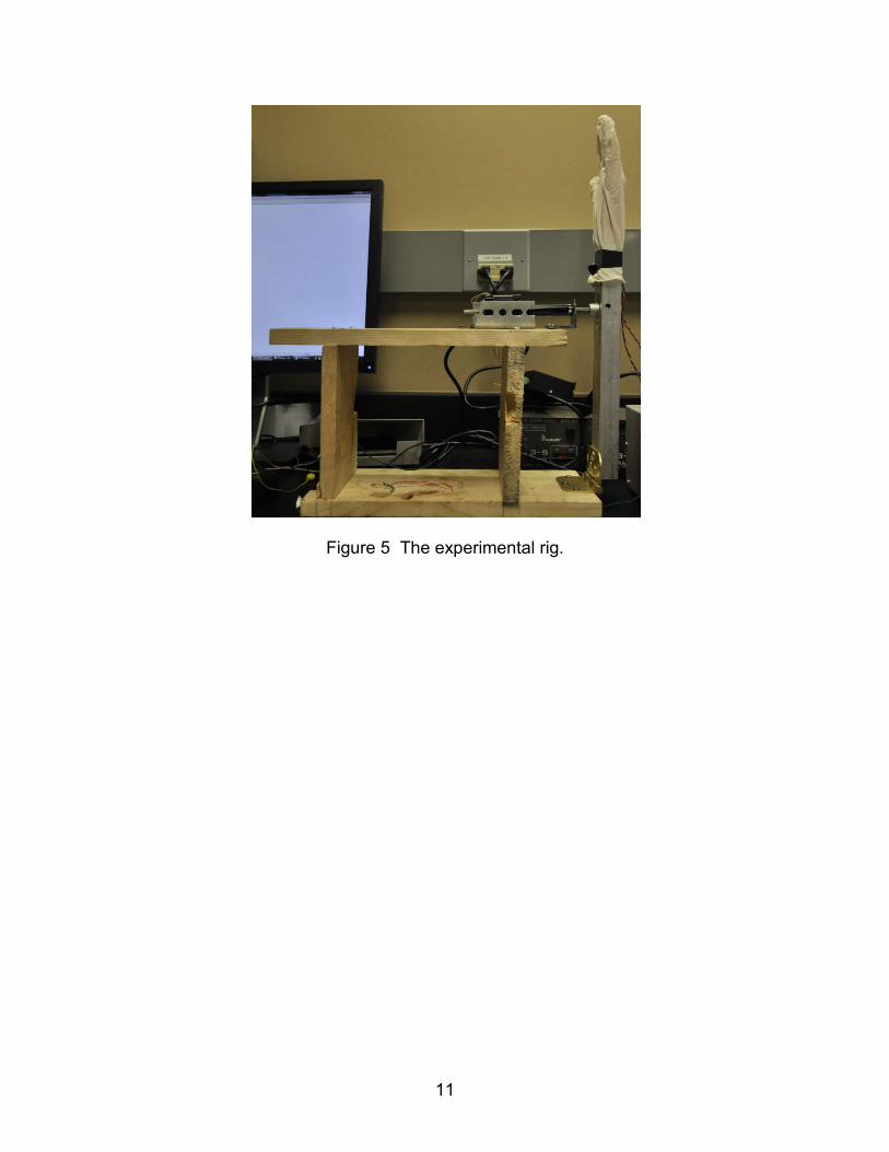
Figure 5 shows the experimental rig after fabrication process. The experimental rig
consists of one linear motor, two springs, one artificial palm, one aluminum pipe, one
hinge and four pieces of wood. Since the experimental rig needs to emulate the wrist
tremor, I connect the artificial palm with the aluminum arm by two springs, which allow
the palm to move forward and backward while the arm is vibrating.
Figure 4 The dimension detail of the experimental rig.
11
Figure 5 The experimental rig.

12
CHAPTER 4
THE EXPERIMENT SETUP AND RESULT ANALYSIS
This chapter describes the experiment setup and the result analysis of energy
harvesting. I also discuss the reason why the MFC (macro fiber composite) films could
not be utilized as the actuator of the human hand tremor suppression.
4.1 Experiment Setup for the Energy Harvesting
The complete set up of the experimental rig used in this study is shown in Figure
6. Figure 7 shows the detail of the energy harvesting glove with different kinds of
piezoelectric materials (MFC (macro fiber composite) and PVDF (polyvinylidene
fluoride).
As shown in the Figure 6, PC is responsible for converting the sinusoid wave
signal to the form which the motor drive could recognize, and this form of electrical
signal is transmitted by a data acquisition board. The motor drive and power supply are
used to drive the linear motor, and the motor moves forward and backward in a certain
frequency, which is determined by the signal from the I/O board. The artificial palm
wears an energy harvesting glove, which is covered by a piece of piezoelectric material.
Since the artificial palm is connected with two springs, it will stretch the glove when it is
vibrating, and therefore a force will strain the piezoelectric material. As a result, the
material will generate a voltage, which will be transferred to the rectifier circuit, and
measured by the oscilloscope.

13
As shown in the Figure 7, the energy harvesting glove is made of an elastic rubber
glove, which is with one piece of piezoelectric material at the back. Its flexibility allows
the artificial palm to freely move forward and backward.
Figure 6 The experimental setup of energy harvesting
(a)MFC (b)PVDF
Figure 7 The energy harvesting glove with MFC and PVDF

14
4.2 Result and Analysis
As shown in Table 1, the energy harvested by MFC and FVDF is very low, it may
be due to two reasons: (1) the piezoelectric materials are not tightly enough attached to
the energy harvesting glove, so that not enough waste mechanical energy could be
harvested. (2) Just one piece of material is not enough, we need to cover the glove with
more piezoelectric materials.
Load Voltage (mV) Power (mW)
Open Circuit 230 N/A
3.3 KΩ 23 0.00016
14.8 KΩ 41 0.00011
38.5 KΩ 89 0.00021
(a) MFC
Load Voltage (mV) Power (mW)
Open Circuit 105 N/A
3.3 KΩ 10 3*10-7
14.8 KΩ 25 0.00004
38.5 KΩ 49 0.00006
(b)PVDF
Table 1 Energy harvesting result

15
CHAPTER 5
SIMULATION OF TREMOR SUPPRESSION
This chapter describes the simulation of tremor suppression with adaptive control
technology by using Matlab Simulink. In this simulation, we apply the active vibration
control technology to suppress the tremor. The tremor signal will be considered as the
“unwanted vibration”, and will be processed by the AVC system to generate a “anti-
tremor” signal to suppress the tremor. In addition, since the frequency range of the
tremor is different from the one of voluntary movement, the “anti-tremor” signal will not
affect the voluntary signal much.
Moreover, in this paper we only conduct the simulation for the tremor
suppression, instead of the real tremor suppression experiment. The reason is that the
MFC actuator needs a very high operating voltage ( up to 1500 V), so it is not safe,
economic and convenient.
5.1 Active Vibration Algorithm
Filtered-X least-mean-square (FXLMS) is one of the most popular ANC/AVC
algorithms [16]. The block program of a ANC/AVC system with FXLMS algorithm is as
shown in Figure 5-1. P(z) is the primary path transfer function, S(z) is the secondary
path transfer function, e(n) is the residual vibration (tremor ), and the x(n) is the
reference signal of the noise.

16
Figure 8 Block diagram of ANC/AVC system with FXLMS algorithm. [16]
The primary vibration is given as,
d(n) = P(n) ∗ x(n) (5-1)
Where, P(n) is the impulse response of the primary path, and x(n) is the reference
signal vector of the vibration source, and ∗ denotes linear convolution.
The antivibration is given as,
y′(n) = s(n) ∗ [wT(n)x(n)] (5-2)
Where, w(n) is the weight coefficient vector of adaptive filter, respectively, s(n) is the
impulse response of the secondary path.
The residual vibration is given as,
e(n) = d(n) − s(n) ∗ [wT(n)x(n)] (5-3)
And the objective function is based on the mean-square error (MSE):
ξ(n) = E[e2(n)] (5-4)
In order to minimize the mean-square error, the weight update equation should be:

17
w(n + 1) = w(n) + ux′(n)e(n) (5-5)
Where u is the step size, x′(n) is the reference signal vector x(n) filtered by the
estimated secondary path transfer function s′(n).
5.2 Computer Simulation
The computer simulation is conducted by using Matlab Simulink with a sample
frequency of 1000 Hz, a voluntary hand movement signal source is of combinations of
1Hz and 2Hz sinusoidal waves, in which the 1Hz component had amplitude of 3 and the
2Hz one had amplitude of 2. Three different sets of data are used as the tremor signal
source. The diagram of the simulation model in Simulink is shown in Figure 9.
As shown in Figure 9, a high pass filter is used to distinguish the tremor signal
from the voluntary movement signal, and the filtered tremor signal is used as the
reference input for the adaptive control system. The movement after tremor suppression
is used as the error signal for the adaptive control system in order to minimize the
involuntary movement, and since the frequency of tremor signal is different from the one
of voluntary movement, it will not affect the voluntary movement.

18
Figure 9 Diagram of the simulation model in Simulink

19
5.3 The Analysis of the Result
5.3.1 First Set of Tremor Signal
The first set of tremor signal is a 8Hz sinusoidal waves with amplitude of 1.5. As
shown in Figure 10, the simulation result indicates that the adaptive control decrease
the amplitude of tremor from 1.5 to less than 0.2.
(a) The origin movement with tremor
(b) The voluntary movement

20
(c) The tremor suppression signal
(d) The residual movement with tremor suppression
(e) The origin tremor

21
(f) The residual tremor after tremor suppression
Figure 10 The simulation result of the first set of tremor signal
The spectra of origin tremor and residual tremor are shown in Figure 11, and the
8Hz tremor is effectively depressed after the adaptive tremor suppression.
(a) The spectra of origin tremor
(b) The spectra of residual tremor
Figure 11 The comparison of the spectra in the first set

22
5.3.2 Second Set of Tremor Signal
The second set of tremor signal of combinations of 8Hz and 12Hz sinusoidal
waves, in which the 8Hz component had amplitude of 1 and the 12Hz one had
amplitude of 0.5. As shown in Figure 12, the simulation result indicates that the adaptive
control decrease the amplitude of tremor from 1.5 to less than 0.5.
(a) The origin movement with tremor
(b) The voluntary movement

23
(c) The tremor suppression signal
(d)The residual movement with tremor suppression
(e) The origin tremor

24
(f)The residual tremor after tremor suppression
Figure 12 The simulation result of the second set of tremor signal
The spectra of origin tremor and residual tremor are shown in Figure 13, and the
8Hz and 12 Hz tremor is effectively depressed after the adaptive tremor suppression.
(a) The spectra of origin tremor
(b) The spectra of residual tremor
Figure 13 The comparison of the spectra in the second set

25
5.3.3 Third Set of Tremor Signal
The third set of tremor signal is of combinations of 8Hz,10Hz and 12Hz
sinusoidal waves, in which the 8Hz component had amplitude of 0.8, 10Hz component
had amplitude of 0.5 and the 12Hz one had amplitude of 0.2. As shown in Figure 14, the
simulation result indicates that the adaptive control decrease the amplitude of tremor
from 1.5 to less than 0.5.
(a) The origin movement with tremor
(b) The voluntary movement

26
(c) The tremor suppression signal
(d)The residual movement with tremor suppression
(e) The origin tremor

27
(f) The residual tremor after tremor suppression
Figure 14 The simulation result of the third set of tremor signal
The spectra of origin tremor and residual tremor are shown in Figure 15, and the
tremor is effectively depressed after the adaptive tremor suppression.
(a) The spectra of origin tremor
(b) The spectra of residual tremor
Figure 15 The comparison of the spectra in the third set

28
According to the analysis and comparison of different kinds of tremor, we could find
that the AVC algorithm works well in different condition, especially in the case of the
tremor of single frequency.

29
CHAPTER 6
CONCLUSIONS AND FUTURE WORK
6.1 Conclusions
In this thesis, tremor suppression with adaptive control technology was simulated,
and the result indicates that it can effectively decrease the amplitude of the tremor and
does not affect much of the voluntary hand movement. The flexibility of the MFC
material is useful for fabricating a tremor suppression glove, but its high operating
voltage (up to 1500 V) makes it not suitable to be used as an actuator for this tremor
suppression, because it is not safe, economic and convenient.
Also, we build an experimental rig to conduct the energy harvesting experiment,
and it is also useful for the tremor suppression experiment in the future. The energy
harvesting experiment result indicates that the voltage harvested from one piece of
MFC could be up to 239mV. The harvested energy is not high enough for meaningful
vibration control.
6.2 Future Work
The main reason that we fail to fabricate the tremor suppression glove is that the
piezoelectric materials we use could not satisfy the requirement. If the operating voltage
of the MFC decreases to an appropriate level, the glove could be manufactured with
MFC. As mentioned previously, since the MFC could harvest a voltage up to 239 mV, if
we cover the energy harvesting glove with more MFC materials, considerable energy
might be harvested to power the vibration sensors and power for the micro controller
unit.

30
REFERENCES
[1] Elble, R. J., and Koller, W. C. 1990. Tremor. The Johns Hopkins University Press, Baltimore, MD.
[2] Gao, J. B. 2004. Analysis of Amplitude and Frequency Variations of Essential and Parkinsonian Tremors. Med. Biol. Eng. Comput 42: 345-349
[3] Pellegrini, B., Faes, L., Nollo, G. and Schena, F. 2004. Quantifying the Contribution of Arm Postural Tremor to the outcome of goal-directed pointing task by displacement measure. Journal of Neuroscience Methods 139: 185-193
[4] Graham, B.B. 2000. Using an Accelerometer Sensor to Measure Human Hand Motion. Master Thesis, Massachusetts Institute of Technology, US
[5] Smaga, S. M. D. 2003. Tremor, American Family Physician, Volume 68, Number 8, 1545-1552.
[6] Meshack, R. P. 2001. The Effects of Weights on the Amplitude and Frequency of Postural Hand Tremor in People with Parkinson’s disease. Master Thesis, Queen’s University, Kingston, Ontario, Canada.
[7] Norman, K.E., Edwards, R. and Beuter, A. 1999. The Measurement of Tremor using a Velocity Transducer: Comparison to Simultaneous Recordings using Transducers of Displacement, Acceleration and Muscle Activity. Journal of Neuroscience Methods, 92: 41-54.
[8] Duval, C. 2006. Rest and Postural Tremors in Patients with Parkinson’s Disease. Brain Research Bulletin, 70: 44-48.
[9] Meshack, R. P. and Norman, K. E. 2002. A Randomized Controlled Trial of the Effects of Weights on Amplitude and Frequency of Postural Hand Tremor in people with Parkinson’s disease. Clinical Rehabilitation, 16: 481-492.
[10] Robert N. Stiles. 1976. Frequency and displacement amplitude relations for normal hand tremor. Journal of Applied Physiology, Vol. 40, No. 1.
[11] Morrison, S., Kerr, G. and Silburn, P. 2007. Bilateral tremor relations in Parkinson’s disease: Effects of mechanical coupling and medication. Parkinsonism Relat Disord doi:10.1016/j.parkreldis.2007.09.004
[12] Hellwig, B., Mund, P., Schelter, B., Guschlbauer, B., Timmer, J. and Lucking, C.H. 2008. A longitudinal study of tremor frequencies in Parkinson’s disease and essential tremor, Clinical Neurophysiology.doi:10.1016/j.clinph.2008.11.002
[13] Treatements for Essential Tremor. American Academic of Neurology from www.aan.com/globals/axon/assets/2585.pdf

31
[14] Henry A Sodano, Justin Lloyd and Daniel J Inman. 2006. An experimental comparison between several active composite actuators for power generation. Smart Mater. Struct. 15 (2006) 1211–1216
[15] Lee Swallow, Elias Siores. 2009. Tremor Suppression Using Smart Textile Fibre Systems. JFBI, Vol.1 No. 4 2009
[16] S. M. Kuo and D. R. Morgan. 1996. Active Noise Control Systems Algorithms and DSP Implementations. John Wiley & Sons, New York, NY, USA, 1996.
[17] P. Li and X. Yu. 2011. Comparison Study of Active Noise Cancelation Algorithms for Impulsive Noise. 2011 ASME International Mechanical Engineering Congress & Exposition (IMECE 2011), Denver, CO, Nov. 11-17, 2011, paper #: IMECE2011-63925.
[18] H. F. Olsen, E. F. May. 1953. Electronic sound absorver. J. Acoust. Soc. America, Vol. 25, No. 6, pp. 135-139.
[19] http://www.haydonkerk.com/LinearActuatorProducts/StepperMotorLinear Actuators/LinearActuatorsHybrid/Size17DSLinearActuator/tabid/81/Default.aspx
[20] Rabih Alkhatib, M. F. Golnaraghi. 2003. Active Structural Vibration Control: A Review. The Shock and Vibration Digest 2003; 35; 367. DOI:10.1177/05831024030355002