Simulation of Spray Transport from Rotary Cup Atomizer · PDF fileSimulation of Spray...
6
Simulation of Spray Transport from Rotary Cup Atomizer using KIVA-3V Hua Huang and Ming-Chia Lai Department of Mechanical Engineering Wayne State University Detroit, Michigan 48202 USA William Meredith Dupont Automotive Troy, Michigan 48007 USA Summary A numerical study of airflow and spray transport from rotary cup atomizer using KIVA-3V is carried out. The numerical result show that the electrostatic field speed up spray droplet speed and improve transfer efficiency. Breakup model produces smaller drops which are entrained into the center recirculation zone. The results of a parametric study considering different cup rotational speed, shaping airflow rate, liquid flow rate, target distance, charge-mass ratio are also summarized. Introduction Rotating or electrical charged fuel sprays have been proposed for diesel engine applications (e.g., Bellan, 1983; Sjoberg, 1999). In an entirely different application in automotive finishing industry, electrostatic rotary bell (ESRB) applicators are used extensively for its higher transfer efficiency of paint particles to the auto body target surface. The spray dynamics with the shaping air is an extremely complicated phenomenon. To simulate the mass, momentum, and energy transfer processes, the interaction between the spray particles, the airflow, and the electrostatic forces must be accounted for. Bellan [1983], True [1983] Elmoursi et. al. [1989], Grace and Dunn [1994] all contributed to the simulation of the process. However, these earlier studies used monodisperse droplet size and charge, and did not consider the momentum coupling between the gas phase and with the dispersed phase. Recently, Shrimpton et al. [1997] used a combined Eulerian/Lagrangian formulation to simulate a capillary tube injection of ethanol onto a flat plate. The effect of the electrical field and the droplet space charge was incorporated into a PISO solver through the use of source terms. They reported that there is large uncertainty concerning the drop charge model and that the spray dynamics is extremely sensitive to the initial condition. However, only the spray shape data were reported for comparison with the experiment, which showed an overestimated radial velocity and an underestimated axial component. Miller et al [1998] simulated ESRB shaping air flow using Powerflow package. They reported that the influence of bell speed, charge-to- mass ratio, electric potential showed good qualitative trends. However, no spray model was used and the shaping air distribution was confined narrowly. Im and Im et al. [1999, 2000] used space-time CE/CS method to extensively simulate the time-dependant shaping air flowfield. The particle trajectory solver and the analytical solution of electrostatic field were applied to simulate the passive particle trajectory. The coupling of the discrete and continuous phases are being developed. The numerical result show that increasing the high voltage setting, the numerical transfer efficiency increased and the spray mass uniformly distributed on the target plane. With high shaping airflow rate, the numerical transfer efficiency decreased and the mass distribution became uniform. This study used KIVA-3V to simulate the same ESRB spray process as in Im’s study, taking advantage of the active spray models and the valve block structure grid facilities. Fig. 1 Near field light-sheet visualization of a water-based ESRB spray.
-
Upload
nguyenkhanh -
Category
Documents
-
view
215 -
download
0
Transcript of Simulation of Spray Transport from Rotary Cup Atomizer · PDF fileSimulation of Spray...

Simulation of Spray Transport from Rotary Cup Atomizer using KIVA-3V
Hua Huang and Ming-Chia LaiDepartment of Mechanical Engineering
Wayne State UniversityDetroit, Michigan 48202 USA
William MeredithDupont Automotive
Troy, Michigan 48007 USA
Summary
A numerical study of airflow and spray transport from rotary cup atomizer using KIVA-3V is carried out. The numerical resultshow that the electrostatic field speed up spray droplet speed and improve transfer efficiency. Breakup model produces smaller dropswhich are entrained into the center recirculation zone. The results of a parametric study considering different cup rotational speed,shaping airflow rate, liquid flow rate, target distance, charge-mass ratio are also summarized.
IntroductionRotating or electrical charged fuel sprays have been proposed for diesel
engine applications (e.g., Bellan, 1983; Sjoberg, 1999). In an entirely differentapplication in automotive finishing industry, electrostatic rotary bell (ESRB)applicators are used extensively for its higher transfer efficiency of paintparticles to the auto body target surface.
The spray dynamics with the shaping air is an extremely complicatedphenomenon. To simulate the mass, momentum, and energy transferprocesses, the interaction between the spray particles, the airflow, and theelectrostatic forces must be accounted for. Bellan [1983], True [1983]Elmoursi et. al. [1989], Grace and Dunn [1994] all contributed to thesimulation of the process. However, these earlier studies used monodispersedroplet size and charge, and did not consider the momentum coupling betweenthe gas phase and with the dispersed phase.
Recently, Shrimpton et al. [1997] used a combined Eulerian/Lagrangianformulation to simulate a capillary tube injection of ethanol onto a flat plate.The effect of the electrical field and the droplet space charge was incorporatedinto a PISO solver through the use of source terms. They reported that there islarge uncertainty concerning the drop charge model and that the spraydynamics is extremely sensitive to the initial condition. However, only thespray shape data were reported for comparison with the experiment, whichshowed an overestimated radial velocity and an underestimated axialcomponent. Miller et al [1998] simulated ESRB shaping air flow usingPowerflow package. They reported that the influence of bell speed, charge-to-mass ratio, electric potential showed good qualitative trends. However, nospray model was used and the shaping air distribution was confined narrowly.Im and Im et al. [1999, 2000] used space-time CE/CS method to extensivelysimulate the time-dependant shaping air flowfield. The particle trajectorysolver and the analytical solution of electrostatic field were applied to simulatethe passive particle trajectory. The coupling of the discrete and continuousphases are being developed. The numerical result show that increasing thehigh voltage setting, the numerical transfer efficiency increased and the spraymass uniformly distributed on the target plane. With high shaping airflow rate,the numerical transfer efficiency decreased and the mass distribution becameuniform. This study used KIVA-3V to simulate the same ESRB spray processas in Im’s study, taking advantage of the active spray models and the valveblock structure grid facilities. Fig. 1 Near field light-sheet visualization of a
water-based ESRB spray.
(2 D) 11 Feb 2000 Example: Multi-Zone 2D Plo t
-50 -40 -30 -20 -10 0 10 20 30 40 500
10
20
Target Surface
Z
Y
(2 D) 11 Feb 2000 Example: Multi-Zone 2D Plo t
(2D) 11 Fe b20 00 Example :Multi-Zone 2D Plot
-10 0 10
20
Shaping Air
Liquid Flow Liquid Flow
Bell Cup
(2D) 11 Fe b20 00 Example :Multi-Zone 2D Plot
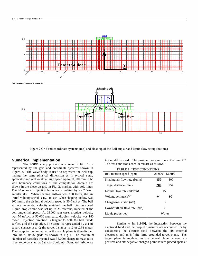
Figure 2 Grid and coordinate systems (top) and close-up of the Bell cup air and liquid flow set up (bottom).
Numerical ImplementationThe ESRB spray process as shown in Fig. 1 is
represented by the grid and coordinate systems shown inFigure 2. The valve body is used to represent the bell cup,having the same physical dimension as in typical sprayapplicator and will rotate at high speed up to 50,000 rpm. Thewall boundary conditions of the computation domain areshown in the close up grid in Fig. 2, marked with bold lines.The 40 or so air injection holes are simulated by an 2.5-mmannular slot. When shaping airflow was 150 l/min, the airinitial velocity speed is 15.0 m/sec. When shaping airflow was300 l/min, the air initial velocity speed is 30.0 m/sec. The bellsurface tangential velocity matched the bell rotation speed.Liquid droplet size was set up to 25 microns, injected at thebell tangential speed. At 25,000 rpm case, droplets velocitywas 70 m/sec; at 50,000 rpm case, droplets velocity was 140m/sec. Injection direction is tangent to both the bell insidesurface and the cup edge. The target is represented by a 1 m2
square surface at z=0; the target distance is .2 or .254 meter.The computation domain after the nozzle plane is then dividedinto 100*100*26 grids as shown in Fig 1. The maximumNumber of particles injected was 36,000; charge to mass ratiois set to be constant at 5 micro Coulomb. Standard turbulence
k-ε model is used. The program was run on a Pentium PC.The test conditions considered are as follows:
TABLE 1. TEST CONDITIONSBell rotation speed (rpm) 25,000 50,000
Shaping air flow rate (l/min) 150 300
Target distance (mm) 200 254
Liquid Flow rate (ml/min) 150
Voltage setting (kV) 0 90
Charge-mass ratio (uC) 5
Downdraft air flow rate (m/s) 0
Liquid properties Water
Similar to Im [1999], the interaction between theelectrical field and the droplet dynamics are accounted for byconsidering the electric field between the six externalelectrodes and an infinite large grounded target plane. Thetarget plane is modeled as the central plane between sixpositive and six negative charged point souces placed apart at

twice the target distance. For simplicity, the repulsive forcesdue to the charge particles and air are neglected. The Taylorbreakup model is also used when invoked. Droplets areassume to stick to the wall upon wall impingement.
(2D) 10 Feb 2000 Example: Simple XY Plot
0
5
10
15
20
25
30
y
(2D) 10 Feb 2000 Example: Simple XY Plot
(2D) 10 Feb 2000 Example: Simple XY Plot
0
5
10
15
20
25
30
y
(2D) 10 Feb 2000 Example: Simple XY Plot
(2D) 10 Feb 2000 Example: Simple XY Plot
0
5
10
15
20
25
30
y
(2D) 10 Feb 2000 Example: Simple XY Plot
(2D) 10 Feb 2000 Example: Simple XY Plot
0
5
10
15
20
25
30
y
(2D) 10 Feb 2000 Example: Simple XY Plot
(2D) 10 Feb 2000 Example: Simple XY Plot
0
5
10
15
20
25
30
y
(2D) 10 Feb 2000 Example: Simple XY Plot
Fig. 3 Shaping air development, ∆t=.02 sec.
Results and Discussions
Shaping air flow
The ESRB spray is a complicated 3-D swirling turbulentflow with highly non-stationary nature. It is difficult todirectly analyze the three-dimensional flow field. In thissection, we plot three velocity components along z-axis forvarious operating conditions. This analysis can give valuableinformation.
Fig. 3 displays the velocity vector dis tribution at y-Zplane, corresponding to the condition of bell speed of 50,000rpm, target distance of 0.25m, and the shaping airflow rate of150 l/min. The flow is still evolving; the toroidal vortexenlarges asymtotically as it bears down on the target wall.Similar to the findings of Im (1999), who did not use any
turbulence model, the high swirl velocity (142 m/s) at theinitial plane (x=0.0 cm) decays rapidly as it approaches thetarget plane.
The spray flow: effects of electrostatics and breakup
Numerical discrete parcels representing spray droplets areinjected at 0.06 sec after onset of the shaping air flow. Fig. 4compares the effect of electrostatic (ES) field for thecondition: bell speed at 50,000 rpm, target distance at 0.20m,shaping air flowrate at 150 l/min, and liquid flowrate at 150ml/min. The high voltage (Fig. 9(b)) drives the spray dropletsto target surface with a higher speed and narrower spray-coneangle. Note the ∆t in Fig. 4a is two-and-a-half times largerthan that in Fig. 4b.
Fig. 5 shows the effect of breakup (BU) model andpolydisperse spray on the discrete parcel distributions. Withthe same operational condition as in the case of Fig. 4a, apolydisperse sprays appears more solid as smaller droplets areentrained into the core recirculation vortex zone.
Implications of operation condition
The effect of operating conditions on film-builduniformity and transfer efficiency can be demonstrated byexamining Fig. 6. The radial liquid flux distributions areplotted along the centerline of the target for different operationconditions to demonstrate their effect on local filmbuild for astationary spray. Since ESRB spray usually are traversedachieve a more uniform coating on the assembly line, theintegrated (with respect to y axis) liquid flux distributions arealso shown for a more realistic comparison. Consistent withexperimental visualization, a higher bell rotation speedproduces a spray that coats a larger area. The spray breakupmodel results in polydispersed spray dropsize distributionswhich has a more uniform filmbuild than the monodispersedspray. The electrostatic drives the spray faster and has a morecompact spray angle. Consequently it will have a positiveeffect on transfer efficiency and surface finish. However, thesimplified electrostatic model used does not show that it alonecan produce a more uniform filmbuild. The predictions showconsistent trends with experimental observation (Lai et al,1997), further validation of prediction will hopefully lead tothe optimization of the sprayer design and operationconditions.
ReferencesAmsden, A.A., (1997) “KIVA-3V: A Block-Structured KIVA
Program for Engines with Vertical or Canted Valves,”Los Alamos National Laboratory Report No. LA-13313-MS.
Bellan, J., (1983) “A New Approach to Soot Control in DieselEngines by Fuel-Drop Charging,” Combution and Flame,51, pp.117-119.
Elmoursi, A.A., (1989) “Laplacian Fields of Bell-TypeElectrostatic Painting Systems,” IEEE Transaction onIndustry Application, vol. 25, No.2, pp.234-240.
Grace, J.M., and Dunn, P.F., (1994) “Droplet Motion in anElectrohydrodynamic Fine Spray,” ICLASS-94, Rouen,France, pp. 1002-1009.

(2 D) 11 F eb 20 00 Exam ple:S imp le XYPlot
-5 0 -25 0 2 5 4 9.99 95x
0
5
1 0
1 5
2 0
y
Sha ping air flow: 150 l/min; Bell speed: 50 ,0 00 rpm; Liquid flow: 15 0 ml/min; time : 0.005 se c; W/O ES fie ld
(2 D) 11 F eb 20 00 Exam ple:S imp le XYPlot
(2 D) 11 F eb 20 00 Exam ple:S imp le XYPlot
-5 0 -25 0 2 5 4 9.99 95x
0
5
1 0
1 5
2 0
y
Sha ping air flow: 150 l/min; Bell speed: 50 ,0 00 rpm; Liquid flow: 15 0 ml/min; time : 0.005 se c; W/O ES fie ld
(2 D) 11 F eb 20 00 Exam ple:S imp le XYPlot
(2 D) 11 F eb 20 00 Exam ple:S imp le XYPlot
-5 0 -25 0 2 5 4 9.99 95x
0
5
1 0
1 5
2 0
y
Sha ping air flow: 150 l/min; Bell speed: 50 ,0 00 rpm; Liquid flow: 15 0 ml/min; time : 0.005 se c; W/O ES fie ld
(2 D) 11 F eb 20 00 Exam ple:S imp le XYPlot
(2 D) 11 F eb 20 00 Exam ple:S imp le XYPlot
-5 0 -25 0 2 5 4 9.99 95x
0
5
1 0
1 5
2 0
y
Shaping air flow: 15 0 l/min; Be ll spee d: 5 0,000 rpm; Liquid flow: 1 50 ml/min; time: 0.02 sec; W/O ES fie ld
(2 D) 11 F eb 20 00 Exam ple:S imp le XYPlot
(2 D) 11 F eb 20 00 Exam ple:S imp le XYPlot
-5 0 -25 0 2 5 4 9.99 95x
0
5
1 0
1 5
2 0
y
Shaping air flow: 15 0 l/min; Be ll spee d: 5 0,000 rpm; Liquid flow: 1 50 ml/min; time: 0.02 sec; W/O ES fie ld
(2 D) 11 F eb 20 00 Exam ple:S imp le XYPlot
Fig. 4a Case with zero electrostatic voltage. Test conditions:bell speed, 50,000 rpm; target distance, 0.20m; shapingairflow rate, 150 l/min; and liquid flow rate, 150 ml/min.∆t=5 msec.
Im, K.-S., Zhang, Z.-C., Yu, S.-T., and Lai, M.-C., (2000)“Numerical Simulation of Shaping Air Flow in the PaintSpray Processes,” ICLASS 2000, Pasadena, CA, July 16-20, 2000.
Im, K.-S., (1999) “An Experimental and Numerical Study ofthe Spray Transfer Processes in an Electrostatic RotatingBell Sprayer,” Ph.D. Thesis, Wayne State University,Mechanical Engineering Dept., Detroit, MI 48202.
Lai, M.-C., Im, K.-S., Liu, Y., Skender, M., M., and Nivi, H.(1997) “Visualization and Measurement of AutomotiveElectrostatic Rotary-Bell Paint Spray Transfer Processes,”Proc. ASME FED. Vol. 244, p. pp. 243-253, IMECE1997, Dallas, TX, Nov. 11-16, 1997.
(2 D) 11 F eb 20 00 Exam ple:S imp le XYPlot
-5 0 -25 0 2 5 4 9.99 95x
0
5
1 0
1 5
2 0
y
Shaping air flow: 1 50 l/min; Bell spe ed: 5 0,000 rpm; Liquidflow: 1 50 ml/min; time: 0 .0 02 sec; With ES fie ld
(2 D) 11 F eb 20 00 Exam ple:S imp le XYPlot
(2 D) 11 F eb 20 00 Exam ple:S imp le XYPlot
-5 0 -25 0 2 5 4 9.99 95x
0
5
1 0
1 5
2 0
y
Shaping air flow: 1 50 l/min; Bell spe ed: 5 0,000 rpm; Liquidflow: 1 50 ml/min; time: 0 .0 02 sec; With ES fie ld
(2 D) 11 F eb 20 00 Exam ple:S imp le XYPlot
(2 D) 11 F eb 20 00 Exam ple:S imp le XYPlot
-5 0 -25 0 2 5 4 9.99 95x
0
5
1 0
1 5
2 0
y
Shaping air flow: 1 50 l/min; Bell spe ed: 5 0,000 rpm; Liquidflow: 1 50 ml/min; time: 0 .0 02 sec; With ES fie ld
(2 D) 11 F eb 20 00 Exam ple:S imp le XYPlot
(2 D) 11 F eb 20 00 Exam ple:S imp le XYPlot
-5 0 -25 0 2 5 4 9.99 95x
0
5
1 0
1 5
2 0
y
Shaping air flow: 15 0 l/min; Be ll spee d: 5 0,000 rpm; Liquid flow: 1 50 ml/min; time: 0.00 8 sec; With ES field
(2 D) 11 F eb 20 00 Exam ple:S imp le XYPlot
(2 D) 11 F eb 20 00 Exam ple:S imp le XYPlot
-5 0 -25 0 2 5 4 9.99 95x
0
5
1 0
1 5
2 0
yShaping a ir flow: 1 50 l/min; Bell speed: 50,00 0 rpm; Liquid flow: 150 ml/min; time: 0 .0 08 sec; With ES fie ld
(2 D) 11 F eb 20 00 Exam ple:S imp le XYPlot
Fig. 4b Electrostatic case with 90,000 Volts. Same testcondition as Fig. 4a. ∆t=2 msec.
Liu, Y., Lai, M.-C., Im, K.-S., Shankagiri, N., Loch, T., andNivi, H., (1999) “An Experimental Investigation of SprayTransfer Processes in an Electrostatic Rotating BellApplicator,” J. Material Manufacturing , SAE Transc.107(5), SAE 982290.
Miller, R., Strumolo, G., Babu, V., Braslaw, J., and Mehta,M., (1998) “Transient CFD Simulations of a BellSprayer,” Proceedings of the IBEC’98, Vol. 4, pp29-37.
Shrimpton, J.S., Watkins, A.P., and Yule, A.J. (1997) “ATurbulent, Transient Charged Spray Model,” Proc. ofICLASS-’97, Seoul, pp. 820-827.
Sjoberg, M., (1999) “In-Cylinder Soot-Control with High-Speed Rotating Injector for DI Diesel Engines,” SAEpaper 1999-01-3489
True, M.A., (1983) “Modeling of Electrostatic Spary Plumes,”IEEE Transaction on Industry Applications, Vol. IA-19,No. 5, pp. 754-758.

0
5
10
15
20
25
-50 -40 -30 -20 -10 0 10 20 30 40 50
0
5
10
15
20
25
-50 -40 -30 -20 -10 0 10 20 30 40 50
0
5
10
15
20
25
-50 -40 -30 -20 -10 0 10 20 30 40 50
0
5
10
15
20
25
-50 -40 -30 -20 -10 0 10 20 30 40 50
0
5
10
15
20
25
-50 -40 -30 -20 -10 0 10 20 30 40 50
0
5
10
15
20
25
-50 -40 -30 -20 -10 0 10 20 30 40 50
Fig. 5a Monodisperse spray discrete parcel distributions. Sametest condition as Fig. 4a. ∆t=5 msec.
0
5
10
15
20
25
-50 -40 -30 -20 -10 0 10 20 30 40 50
0
5
10
15
20
25
-50 -40 -30 -20 -10 0 10 20 30 40 50
0
5
10
15
20
25
-50 -40 -30 -20 -10 0 10 20 30 40 50
0
5
10
15
20
25
-50 -40 -30 -20 -10 0 10 20 30 40 50
0
5
10
15
20
25
-50 -40 -30 -20 -10 0 10 20 30 40 50
0
5
10
15
20
25
-50 -40 -30 -20 -10 0 10 20 30 40 50
Fig. 5b Spray discrete parcel distributions with breakup model.Same test condition as Fig. 4a. ∆t=5 msec

0
0.04
0.08
0.12
0.16
-50 -40 -30 -20 -10 0 10 20 30 40 50
distance [cm]
Acc
um
ula
tio
n %
Paint distribution at centersectionAccumulation
Shaping air: 150 l/min; Rotation speed: 25,000 rpm; Liquid flow rate: 150 ml/min;D0: 25µm; no ES or BU model.
0
0.04
0.08
0.12
0.16
-50 -40 -30 -20 -10 0 10 20 30 40 50
distance [cm}
Acc
um
ula
tio
n %
Paint distribution at centersectionAccumulation
Shaping air: 150 l/min; Rotation speed: 50,000 rpm; Liquid flow rate: 150 ml/min;D0: 25µm; no ES or BU model.
0
0.04
0.08
0.12
0.16
-50 -40 -30 -20 -10 0 10 20 30 40 50
distance [cm]
Acc
um
ual
tio
n %
Paint distribution at centersectionAccumulation
Shaping air: 150 l/min; Rotation speed: 50,000 rpm; Liquid flow rate: 150 ml/min;D0: 30µm; with BU model.
0
0.04
0.08
0.12
0.16
-50 -40 -30 -20 -10 0 10 20 30 40 50
distance [cm]
Acc
um
ula
tio
n %
Paint distribution atcenter sectionAccumulation
Shaping air: 150 l/min Rotation speed: 50,000 rpm Liquid flow rate: 150 ml/minD0: 25µm; with ES model.
Fig. 6 Effect of operation conditions on filmbuild uniformity.