Synthesis of Missile Autopilots Robust to the Presence of ...
THE SIMULATION ENVIRONMENT
The Common Simulation Interface (CSI)
The CSI framework is based on the High Level Architecture (HLA) standard and is designed for distributed simulation of complex systems (Husteli 2005). This communication framework is developed by the Norwegian Marine Technology Research Institute (Marintek) in cooperation with Rolls Royce Marine Dept. and is written in Java.1 Communication on he CSI bus is performed by XML streams over a TCP socket connection, and the framework consists of one server and one or more clients. The server is a multithreaded Java application with one thread serving each client. Each client consists of an application called a federate. The federate can be written in any language supporting socket connections. In addition to Java, implementations have been done using C++, C#, as well as Matlab. Each federate exists as an independent process in interaction with all other federates on the CSI bus. A federate contains one or more objects, which publish their states as attributes. The system can be modified or extended with new federates as required. For the system to operate in real time compared to an actual process, one federate must have access to a hardware clock to set an absolute pace of the execution. It is also possible to let a federate execute asynchronously of the other federates (Rekdalsbakken and Styve 2007). The Control Development Platform
The Control Development Platform (CDP)2 is a hardware independent software development environment for distributed real-time applications. The functionality of the modules constituting a CDP application is defined by CDP Component Models. A CDP Component Model is defined by the tool CDP Developer and consists of a state machine and all the data included in the module. All the information constituting the properties of the model is saved on XML format in the file model.xml. The CDP Component Models are compiled into C++ classes. The models of an application are connected through CDP Connectors, which constitute a framework for message exchange. To run an application the models have to be instantiated. This is done by creating a CDP Component on basis of the definitions in the model.xml file. The model configuration is given in a file called component.xml, which specifies the communication with other components. The file application.xml defines which CDP components the application contains and the chosen hardware platform. On basis of this framework CDP will automatically generate all project files, C++ and XML files for the application. The developer just has to include his specific code, e. g. an autopilot controller. There also exist a number of additional CDP tools to build GUIs, simulate the system behaviour, monitor and acquire process variables, and so on
1 The CSI bus is a proprietary product of Marintek 2 The CDP system is a proprietary product of ICD AS.
(Industrial Control Design 2006a). This integrated development environment introduces the researcher to the simulator environment by a much lower threshold than traditional programming systems, and considerably cuts the time to prepare and run the models. System Integration
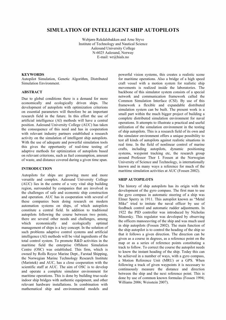
The communication medium is Ethernet, and the CSI framework allows all kinds of simulation models to be integrated in the simulation environment. The CDP platform is integrated in the CSI system through a CDP component called a CSI client for CDP (Industrial Control Design 2006b). This CSI client is able to create CSI objects and also to support the transfer of messages from the CDP system to federates (and objects) over the CSI bus. Also an UDPASCII server is included in the CDP system to communicate between the CDP system and an external user interface. Several ship- and propulsion models, which are developed by either Marintek or OSC, are available for testing, and new models are easily included. The map system MaxSea is available on an NMEA protocol over TCP interface for plotting of the ship position on basis of information available from the ship simulator. The principle of the simulation environment is shown in Figure 1. TRADITIONAL CONTROL
With access to the described integrated simulation environment a context exists for the possible simulation of all relevant ship operations. With regard to autopilots both traditional regulators and all kinds of modern control methods may be tested under realistic conditions. The simulator runs in real time compared to the ship operations. This is achieved by including a federate with access to a hardware clock and letting this federate control the update frequency of the system. The time interval T∆ is chosen in accordance with the time constants of the simulated process, so as to keep track with the fastest responses. The drawback of this regime is that simulations take a lot of time. It takes time to move a ship and as long as real ship models are used, there is no possibility to speed up the process. In the following some examples of the use of traditional control systems are presented. These simulations are in many cases performed as student projects at AUC. The Figures and examples are taken from such projects, especially from one B.Sc. thesis (Haugen et. al. 2007). Heading Control
Traditional heading control is usually realized by a cascaded control system with an internal feedback loop from the ship rotational speed. The internal loop will keep the ship rotational speed within limits, and a big overshoot from the reference heading direction will be avoided by a more moderate and contiguously change in the rudder angle. In this way better course following is obtained and the ship motion will be smoother. The principle is shown in Figure 2.
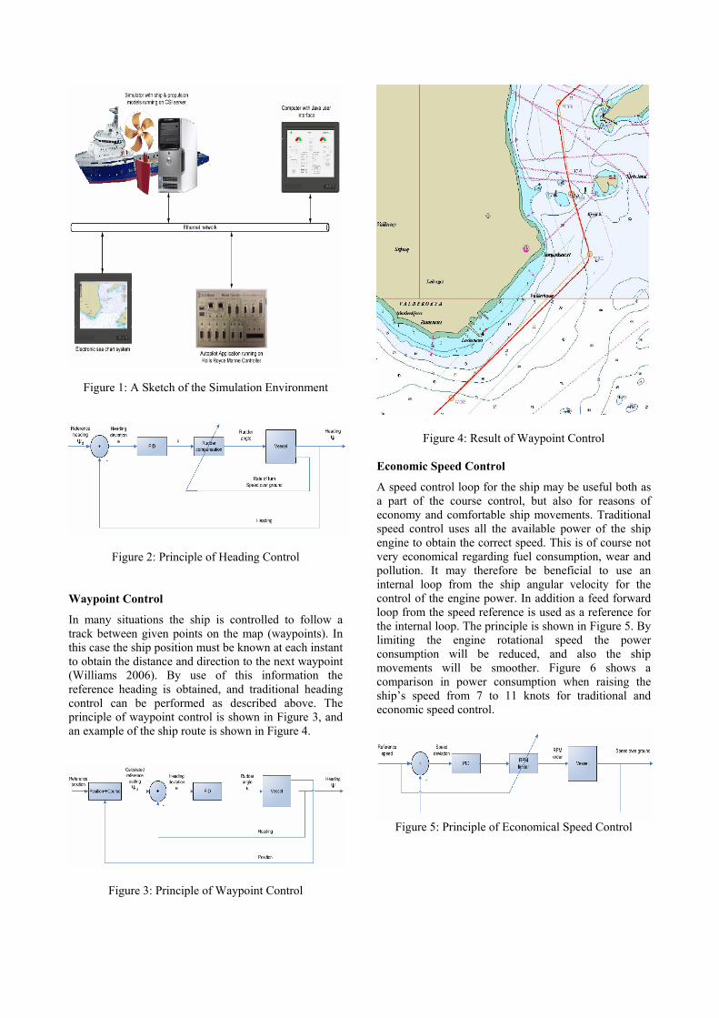
Figure 1: A Sketch of the Simulation Environment
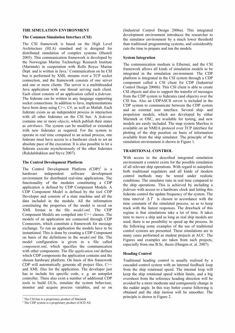
Figure 2: Principle of Heading Control Waypoint Control
In many situations the ship is controlled to follow a track between given points on the map (waypoints). In this case the ship position must be known at each instant to obtain the distance and direction to the next waypoint (Williams 2006). By use of this information the reference heading is obtained, and traditional heading control can be performed as described above. The principle of waypoint control is shown in Figure 3, and an example of the ship route is shown in Figure 4.
Figure 3: Principle of Waypoint Control
Figure 4: Result of Waypoint Control Economic Speed Control
A speed control loop for the ship may be useful both as a part of the course control, but also for reasons of economy and comfortable ship movements. Traditional speed control uses all the available power of the ship engine to obtain the correct speed. This is of course not very economical regarding fuel consumption, wear and pollution. It may therefore be beneficial to use an internal loop from the ship angular velocity for the control of the engine power. In addition a feed forward loop from the speed reference is used as a reference for the internal loop. The principle is shown in Figure 5. By limiting the engine rotational speed the power consumption will be reduced, and also the ship movements will be smoother. Figure 6 shows a comparison in power consumption when raising the ship’s speed from 7 to 11 knots for traditional and economic speed control.
Figure 5: Principle of Economical Speed Control
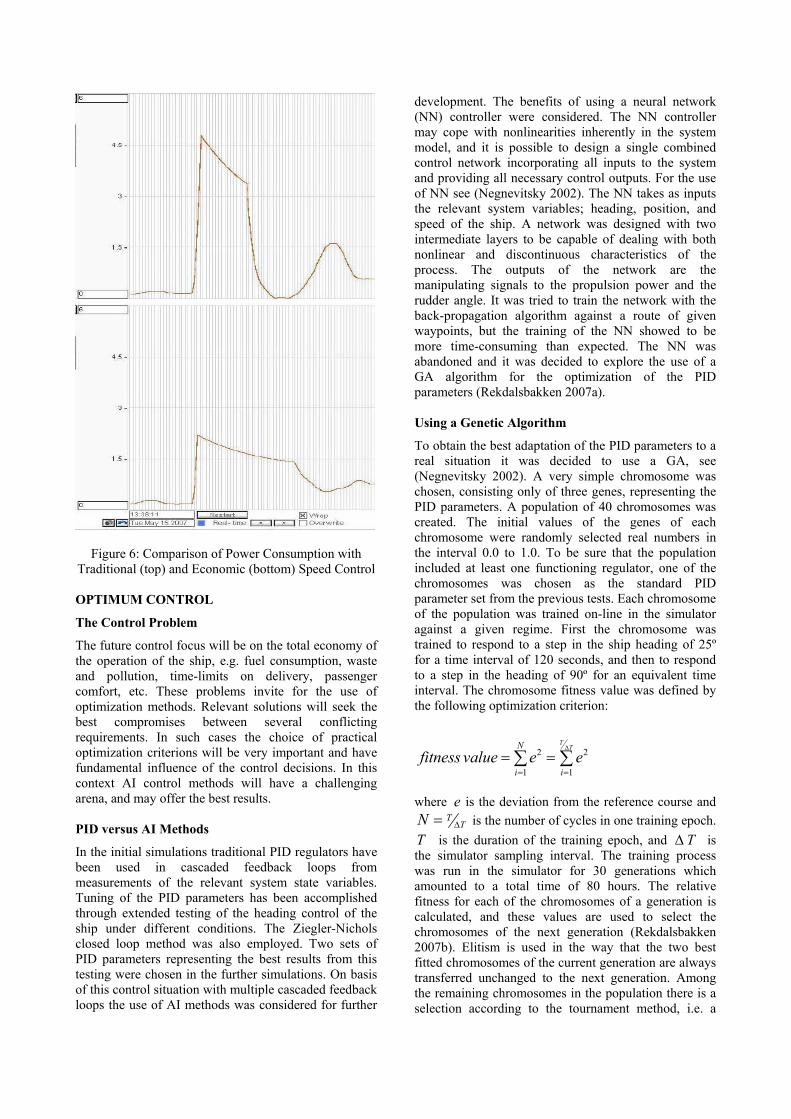
Figure 6: Comparison of Power Consumption with Traditional (top) and Economic (bottom) Speed Control OPTIMUM CONTROL
The Control Problem
The future control focus will be on the total economy of the operation of the ship, e.g. fuel consumption, waste and pollution, time-limits on delivery, passenger comfort, etc. These problems invite for the use of optimization methods. Relevant solutions will seek the best compromises between several conflicting requirements. In such cases the choice of practical optimization criterions will be very important and have fundamental influence of the control decisions. In this context AI control methods will have a challenging arena, and may offer the best results. PID versus AI Methods
In the initial simulations traditional PID regulators have been used in cascaded feedback loops from measurements of the relevant system state variables. Tuning of the PID parameters has been accomplished through extended testing of the heading control of the ship under different conditions. The Ziegler-Nichols closed loop method was also employed. Two sets of PID parameters representing the best results from this testing were chosen in the further simulations. On basis of this control situation with multiple cascaded feedback loops the use of AI methods was considered for further
development. The benefits of using a neural network (NN) controller were considered. The NN controller may cope with nonlinearities inherently in the system model, and it is possible to design a single combined control network incorporating all inputs to the system and providing all necessary control outputs. For the use of NN see (Negnevitsky 2002). The NN takes as inputs the relevant system variables; heading, position, and speed of the ship. A network was designed with two intermediate layers to be capable of dealing with both nonlinear and discontinuous characteristics of the process. The outputs of the network are the manipulating signals to the propulsion power and the rudder angle. It was tried to train the network with the back-propagation algorithm against a route of given waypoints, but the training of the NN showed to be more time-consuming than expected. The NN was abandoned and it was decided to explore the use of a GA algorithm for the optimization of the PID parameters (Rekdalsbakken 2007a). Using a Genetic Algorithm
To obtain the best adaptation of the PID parameters to a real situation it was decided to use a GA, see (Negnevitsky 2002). A very simple chromosome was chosen, consisting only of three genes, representing the PID parameters. A population of 40 chromosomes was created. The initial values of the genes of each chromosome were randomly selected real numbers in the interval 0.0 to 1.0. To be sure that the population included at least one functioning regulator, one of the chromosomes was chosen as the standard PID parameter set from the previous tests. Each chromosome of the population was trained on-line in the simulator against a given regime. First the chromosome was trained to respond to a step in the ship heading of 25º for a time interval of 120 seconds, and then to respond to a step in the heading of 90º for an equivalent time interval. The chromosome fitness value was defined by the following optimization criterion:
2 2
1 1
TTN
i ifitness value e e
∆
= == =∑ ∑
where e is the deviation from the reference course and
TTN ∆= is the number of cycles in one training epoch.
T is the duration of the training epoch, and T∆ is the simulator sampling interval. The training process was run in the simulator for 30 generations which amounted to a total time of 80 hours. The relative fitness for each of the chromosomes of a generation is calculated, and these values are used to select the chromosomes of the next generation (Rekdalsbakken 2007b). Elitism is used in the way that the two best fitted chromosomes of the current generation are always transferred unchanged to the next generation. Among the remaining chromosomes in the population there is a selection according to the tournament method, i.e. a
given number of chromosomes are randomly drawn, and among these the chromosome with the highest fitness value is chosen (Miller and Goldberg 1995). This procedure is repeated until a new chromosome population is formed. This population will now be exposed to a selection for crossover and mutation. The probability of crossover for a randomly selected pair of chromosomes was set to 70%. The probability for a gene of a chromosome to be exposed to a mutation was initially set to 1%. The mutation results in a new random value between 0.0 and 1.0 for the selected gene. The chromosome and the parameters used in the GA are shown in Table 1.
Table 1: Parameters used in the Genetic Algorithm
NAME VALUE No. of chrom. in population 40 No. of genes in chromosome 3 No. of variables in each gene 1 Initial value of the genes random in [0.0,1.0] Epoch time 240 seconds Probability for crossover 70 % Probability for mutations 1 % Change in mutation random in [0.0,1.0]
RESULTS
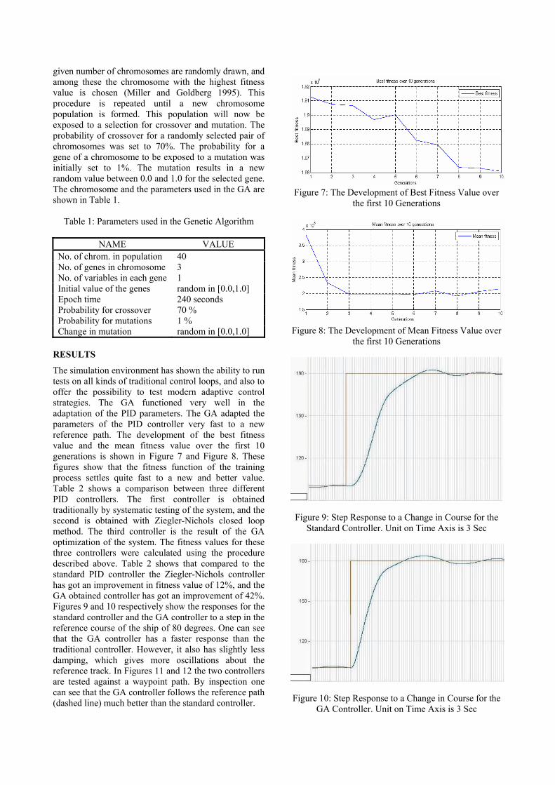
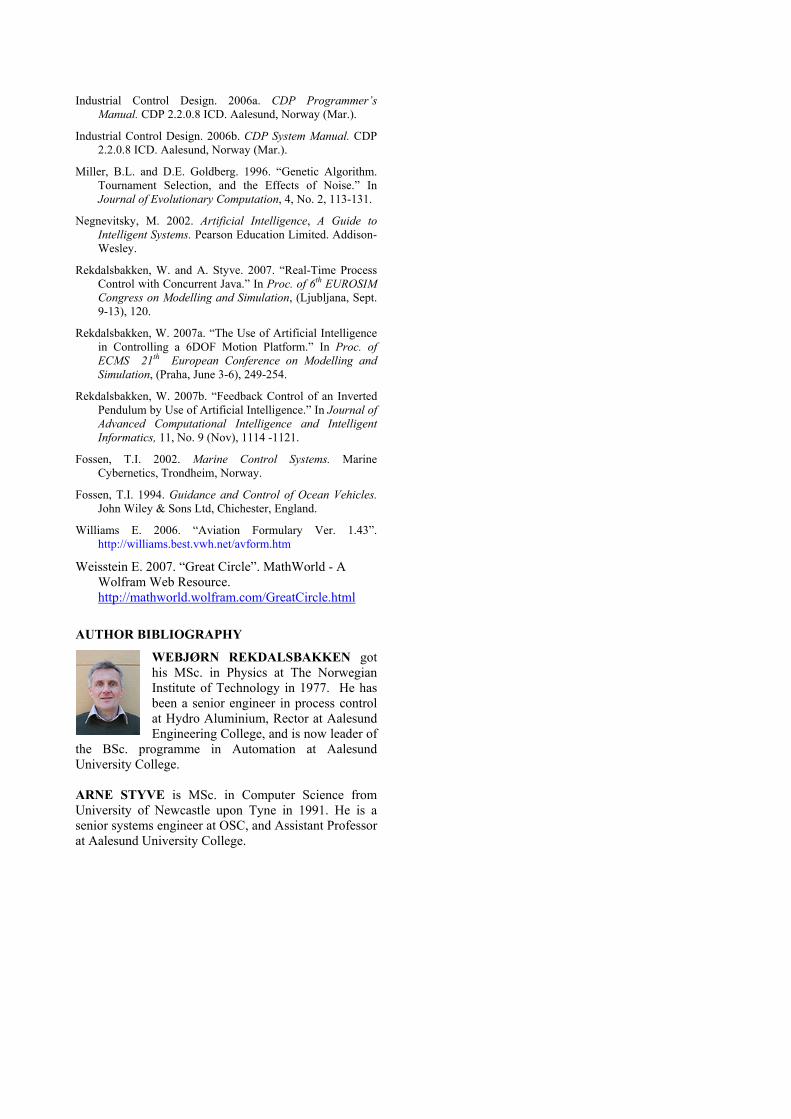
The simulation environment has shown the ability to run tests on all kinds of traditional control loops, and also to offer the possibility to test modern adaptive control strategies. The GA functioned very well in the adaptation of the PID parameters. The GA adapted the parameters of the PID controller very fast to a new reference path. The development of the best fitness value and the mean fitness value over the first 10 generations is shown in Figure 7 and Figure 8. These figures show that the fitness function of the training process settles quite fast to a new and better value. Table 2 shows a comparison between three different PID controllers. The first controller is obtained traditionally by systematic testing of the system, and the second is obtained with Ziegler-Nichols closed loop method. The third controller is the result of the GA optimization of the system. The fitness values for these three controllers were calculated using the procedure described above. Table 2 shows that compared to the standard PID controller the Ziegler-Nichols controller has got an improvement in fitness value of 12%, and the GA obtained controller has got an improvement of 42%. Figures 9 and 10 respectively show the responses for the standard controller and the GA controller to a step in the reference course of the ship of 80 degrees. One can see that the GA controller has a faster response than the traditional controller. However, it also has slightly less damping, which gives more oscillations about the reference track. In Figures 11 and 12 the two controllers are tested against a waypoint path. By inspection one can see that the GA controller follows the reference path (dashed line) much better than the standard controller.
Figure 7: The Development of Best Fitness Value over
the first 10 Generations
Figure 8: The Development of Mean Fitness Value over
the first 10 Generations
Figure 9: Step Response to a Change in Course for the Standard Controller. Unit on Time Axis is 3 Sec
Figure 10: Step Response to a Change in Course for the
GA Controller. Unit on Time Axis is 3 Sec
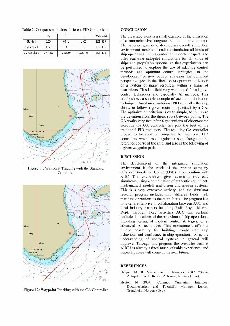
Table 2: Comparison of three different PID Controllers
Figure 11: Waypoint Tracking with the Standard
Controller
Figure 12: Waypoint Tracking with the GA Controller
CONCLUSION
The presented work is a small example of the utilization of a comprehensive integrated simulation environment. The superior goal is to develop an overall simulation environment capable of realistic simulation all kinds of ship operations. In this context an important aspect is to offer real-time autopilot simulations for all kinds of ships and propulsion systems, so that experiments can be performed to explore the use of adaptive control methods and optimum control strategies. In the development of new control strategies the dominant perspective goes in the direction of optimum utilization of a system of many resources within a frame of restrictions. This is a field very well suited for adaptive control techniques and especially AI methods. This article shows a simple example of such an optimization technique. Based on a traditional PID controller the ship ability to follow a given route is optimized by a GA. The optimization criterion is quite simple, to minimize the deviation from the direct route between points. The GA works very fast; after 6 generations of chromosome selection the GA controller has past the best of the traditional PID regulators. The resulting GA controller proved to be superior compared to traditional PID controllers when tested against a step change in the reference course of the ship, and also in the following of a given waypoint path. DISCUSSION
The development of the integrated simulation environment is the work of the private company Offshore Simulation Centre (OSC) in cooperation with AUC. This environment gives access to true-scale simulators, using a combination of authentic equipment, mathematical models and vision and motion systems. This is a very extensive activity, and the simulator research program includes many different fields, with maritime operations as the main focus. The program is a long-term enterprise in collaboration between AUC and local industry partners including Rolls Royce Marine Dept. Through these activities AUC can perform realistic simulations of the behaviour of ship operations, including testing of modern control strategies, e. g. advanced AI techniques. This environment offers a unique possibility for building insight into ship behaviour and confidence in ship operations. Also, the understanding of control systems in general will improve. Through this program the scientific staff at AUC has already gained much valuable experience, and hopefully more will come in the near future. REFERENCES Haugen M, B. Maroe and E. Rangnes. 2007. “Smart
Autopilot”. AUC Report, Aalesund, Norway (June).
Husteli N. 2005. “Common Simulation Interface. Documentation and Tutorial”. Marintek Report, Trondheim, Norway (Oct.).
Industrial Control Design. 2006a. CDP Programmer’s Manual. CDP 2.2.0.8 ICD. Aalesund, Norway (Mar.).
Industrial Control Design. 2006b. CDP System Manual. CDP 2.2.0.8 ICD. Aalesund, Norway (Mar.).
Miller, B.L. and D.E. Goldberg. 1996. “Genetic Algorithm. Tournament Selection, and the Effects of Noise.” In Journal of Evolutionary Computation, 4, No. 2, 113-131.
Negnevitsky, M. 2002. Artificial Intelligence, A Guide to Intelligent Systems. Pearson Education Limited. Addison-Wesley.
Rekdalsbakken, W. and A. Styve. 2007. “Real-Time Process Control with Concurrent Java.” In Proc. of 6th EUROSIM Congress on Modelling and Simulation, (Ljubljana, Sept. 9-13), 120.
Rekdalsbakken, W. 2007a. “The Use of Artificial Intelligence in Controlling a 6DOF Motion Platform.” In Proc. of ECMS 21th European Conference on Modelling and Simulation, (Praha, June 3-6), 249-254.
Rekdalsbakken, W. 2007b. “Feedback Control of an Inverted Pendulum by Use of Artificial Intelligence.” In Journal of Advanced Computational Intelligence and Intelligent Informatics, 11, No. 9 (Nov), 1114 -1121.
Fossen, T.I. 2002. Marine Control Systems. Marine Cybernetics, Trondheim, Norway.
Fossen, T.I. 1994. Guidance and Control of Ocean Vehicles. John Wiley & Sons Ltd, Chichester, England.
Williams E. 2006. “Aviation Formulary Ver. 1.43”. http://williams.best.vwh.net/avform.htm
Weisstein E. 2007. “Great Circle”. MathWorld - A Wolfram Web Resource. http://mathworld.wolfram.com/GreatCircle.html
AUTHOR BIBLIOGRAPHY
WEBJØRN REKDALSBAKKEN got his MSc. in Physics at The Norwegian Institute of Technology in 1977. He has been a senior engineer in process control at Hydro Aluminium, Rector at Aalesund Engineering College, and is now leader of
the BSc. programme in Automation at Aalesund University College. ARNE STYVE is MSc. in Computer Science from University of Newcastle upon Tyne in 1991. He is a senior systems engineer at OSC, and Assistant Professor at Aalesund University College.