Simulation of Electrostatic Rotary Bell Spray … of Electrostatic Rotary Bell Spray Painting in ......
8
ICLASS 2012, 12 th Triennial International Conference on Liquid Atomization and Spray Systems, Heidelberg, Germany, September 2-6, 2012 Simulation of Electrostatic Rotary Bell Spray Painting in Automotive Paint Shops A. Mark *1 , B. Andersson 1 , S. Tafuri 1 , K. Engström 1 , H. Söröd 2 , F. Edelvik 1 , J. S. Carlson 1 1 Fraunhofer-Chalmers Centre, Chalmers Science Park, Gothenburg, Sweden 2 Swerea IVF, Mölndal, Sweden [email protected], [email protected], [email protected], [email protected], [email protected], [email protected], [email protected] Abstract A new framework for simulation of electrostatic spray painting is proposed based on novel algorithms for coupled simulations of air flow, electromagnetic fields and paint droplets. Particularly important for the computational efficiency is the Navier-Stokes solver. The incompressible solver is based on a finite volume discretization on a dynamic Cartesian octree grid and unique immersed boundary methods are used to model the presence of objects in the fluid. This enables modeling of moving objects at virtually no additional computational cost, and greatly simplifies preprocessing by avoiding the cumbersome generation of a body conforming mesh. To validate the sim- ulation framework an extensive measurement campaign has been performed. Several test plates and car fenders were painted with different process conditions and robot paths. The same cases were then simulated and overall the agreement between simulations and experiments are remarkably good. The very efficient implementation gives a major improvement of computational speed compared to other approaches and makes it possible to simulate spray painting of a full car in just a few hours on a standard computer. Introduction The paint and surface treatment processes in automotive paint shops are characterized by multi-phase and free surface flows, multi-physics, multi-scale phenomena, and large moving geometries. This poses great challenges for mathematical modeling and simulation. The current situation in the automotive industry is therefore to rely on in- dividual experience and physical validation for improving these processes. Having access to tools that incorporate the flexibility of robotic path planning with fast and efficient simulation of the processes would be advantageous, since such tools can contribute to reduce the time required for introduction of new models, reduce the cycle-time, reduce the environmental impact and increase quality. In this paper the focus is on spray painting with the Electrostatic Rotary Bell Sprayer (ERBS) technique. Paint is injected at the center of a rotating bell; the paint forms a film on the bottom side of the bell and is atomized at the edge. The droplets are charged electrostatically and driven towards the target both by shaping air surrounding the rotating bell and by a potential difference in the order of 50-100 kV between paint applicator and target. A few attempts to simulate the complex process can be found in the literature [1, 2, 3, 4]. In particular, Domnick et al. have made extensive modeling work for wet paint as well as for powder coating devices [5, 6]. A systematic validation for realistic geometries is missing and another major drawback with earlier approaches is that the simulation times are prohibitively long for the tools to be industrially useful. This is partly due to the fact that the simulation methods do not handle moving geometries in an efficient way. The aim of this paper is to present a new framework that allows for accurate simulations of spray painting of a car in just a few hours on a standard computer. To achieve this, novel algorithms are developed for coupled simu- lations of air flow, electromagnetic fields and charged paint droplets. Particularly important for the computational efficiency is the Navier-Stokes solver. Unique immersed boundary methods are used to model the presence of objects in the fluid and they are combined with an adaptive Cartesian octree grid [8, 9]. This enables modeling of moving objects at virtually no additional computational cost, and greatly simplifies preprocessing by avoiding the cumbersome generation of a body conforming mesh. The electrostatic solver is based on the same discretization framework and immersed boundary conditions are used to set the voltages at the applicator and target geometry. The paint droplets are simulated as Lagrangian particles and their motion is given by the Basset-Boussinesq-Oseen (BBO) equation. To validate the simulation framework an extensive measurement campaign was performed. The droplet size distribution, and the air and droplet velocities close to the bell, were measured for different process parameters us- ing a Malvern and laser doppler anemometry (LDA), respectively. The break-up process is currently not simulated * Corresponding author: [email protected] 1
Transcript of Simulation of Electrostatic Rotary Bell Spray … of Electrostatic Rotary Bell Spray Painting in ......

ICLASS 2012, 12th Triennial International Conference on Liquid Atomization and Spray Systems, Heidelberg, Germany, September 2-6, 2012
Simulation of Electrostatic Rotary Bell Spray Painting in Automotive Paint Shops
A. Mark∗1, B. Andersson1, S. Tafuri1, K. Engström1, H. Söröd2, F. Edelvik1, J. S. Carlson1
1Fraunhofer-Chalmers Centre, Chalmers Science Park, Gothenburg, Sweden2Swerea IVF, Mölndal, Sweden
[email protected], [email protected],[email protected], [email protected], [email protected],
[email protected], [email protected]
AbstractA new framework for simulation of electrostatic spray painting is proposed based on novel algorithms for coupledsimulations of air flow, electromagnetic fields and paint droplets. Particularly important for the computationalefficiency is the Navier-Stokes solver. The incompressible solver is based on a finite volume discretization on adynamic Cartesian octree grid and unique immersed boundary methods are used to model the presence of objectsin the fluid. This enables modeling of moving objects at virtually no additional computational cost, and greatlysimplifies preprocessing by avoiding the cumbersome generation of a body conforming mesh. To validate the sim-ulation framework an extensive measurement campaign has been performed. Several test plates and car fenderswere painted with different process conditions and robot paths. The same cases were then simulated and overall theagreement between simulations and experiments are remarkably good. The very efficient implementation gives amajor improvement of computational speed compared to other approaches and makes it possible to simulate spraypainting of a full car in just a few hours on a standard computer.
IntroductionThe paint and surface treatment processes in automotive paint shops are characterized by multi-phase and free
surface flows, multi-physics, multi-scale phenomena, and large moving geometries. This poses great challenges formathematical modeling and simulation. The current situation in the automotive industry is therefore to rely on in-dividual experience and physical validation for improving these processes. Having access to tools that incorporatethe flexibility of robotic path planning with fast and efficient simulation of the processes would be advantageous,since such tools can contribute to reduce the time required for introduction of new models, reduce the cycle-time,reduce the environmental impact and increase quality.
In this paper the focus is on spray painting with the Electrostatic Rotary Bell Sprayer (ERBS) technique. Paintis injected at the center of a rotating bell; the paint forms a film on the bottom side of the bell and is atomized atthe edge. The droplets are charged electrostatically and driven towards the target both by shaping air surroundingthe rotating bell and by a potential difference in the order of 50-100 kV between paint applicator and target. A fewattempts to simulate the complex process can be found in the literature [1, 2, 3, 4]. In particular, Domnick et al. havemade extensive modeling work for wet paint as well as for powder coating devices [5, 6]. A systematic validationfor realistic geometries is missing and another major drawback with earlier approaches is that the simulation timesare prohibitively long for the tools to be industrially useful. This is partly due to the fact that the simulationmethods do not handle moving geometries in an efficient way.
The aim of this paper is to present a new framework that allows for accurate simulations of spray painting of acar in just a few hours on a standard computer. To achieve this, novel algorithms are developed for coupled simu-lations of air flow, electromagnetic fields and charged paint droplets. Particularly important for the computationalefficiency is the Navier-Stokes solver. Unique immersed boundary methods are used to model the presence ofobjects in the fluid and they are combined with an adaptive Cartesian octree grid [8, 9]. This enables modeling ofmoving objects at virtually no additional computational cost, and greatly simplifies preprocessing by avoiding thecumbersome generation of a body conforming mesh. The electrostatic solver is based on the same discretizationframework and immersed boundary conditions are used to set the voltages at the applicator and target geometry.The paint droplets are simulated as Lagrangian particles and their motion is given by the Basset-Boussinesq-Oseen(BBO) equation.
To validate the simulation framework an extensive measurement campaign was performed. The droplet sizedistribution, and the air and droplet velocities close to the bell, were measured for different process parameters us-ing a Malvern and laser doppler anemometry (LDA), respectively. The break-up process is currently not simulated∗Corresponding author: [email protected]
1
12th ICLASS 2012 Simulation of Electrostatic Rotary Bell Spray Painting in Automotive Paint Shops
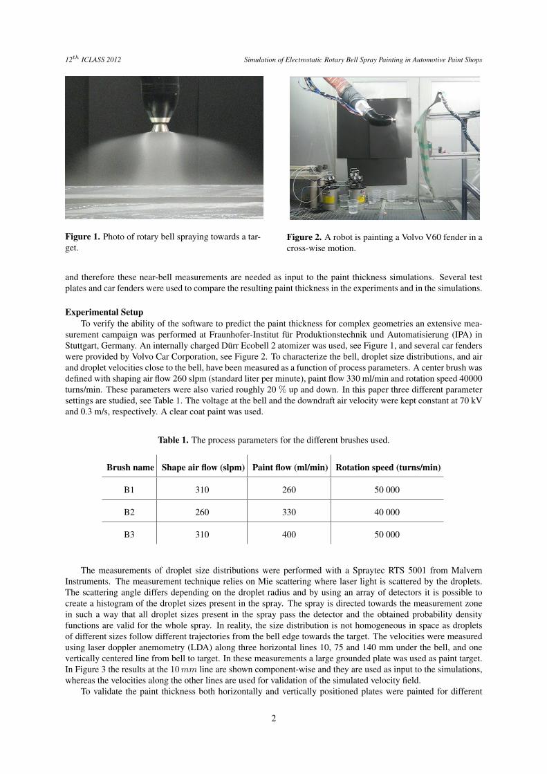
Figure 1. Photo of rotary bell spraying towards a tar-get.
Figure 2. A robot is painting a Volvo V60 fender in across-wise motion.
and therefore these near-bell measurements are needed as input to the paint thickness simulations. Several testplates and car fenders were used to compare the resulting paint thickness in the experiments and in the simulations.
Experimental SetupTo verify the ability of the software to predict the paint thickness for complex geometries an extensive mea-
surement campaign was performed at Fraunhofer-Institut für Produktionstechnik und Automatisierung (IPA) inStuttgart, Germany. An internally charged Dürr Ecobell 2 atomizer was used, see Figure 1, and several car fenderswere provided by Volvo Car Corporation, see Figure 2. To characterize the bell, droplet size distributions, and airand droplet velocities close to the bell, have been measured as a function of process parameters. A center brush wasdefined with shaping air flow 260 slpm (standard liter per minute), paint flow 330 ml/min and rotation speed 40000turns/min. These parameters were also varied roughly 20 % up and down. In this paper three different parametersettings are studied, see Table 1. The voltage at the bell and the downdraft air velocity were kept constant at 70 kVand 0.3 m/s, respectively. A clear coat paint was used.
Table 1. The process parameters for the different brushes used.
Brush name Shape air flow (slpm) Paint flow (ml/min) Rotation speed (turns/min)
B1 310 260 50 000
B2 260 330 40 000
B3 310 400 50 000
The measurements of droplet size distributions were performed with a Spraytec RTS 5001 from MalvernInstruments. The measurement technique relies on Mie scattering where laser light is scattered by the droplets.The scattering angle differs depending on the droplet radius and by using an array of detectors it is possible tocreate a histogram of the droplet sizes present in the spray. The spray is directed towards the measurement zonein such a way that all droplet sizes present in the spray pass the detector and the obtained probability densityfunctions are valid for the whole spray. In reality, the size distribution is not homogeneous in space as dropletsof different sizes follow different trajectories from the bell edge towards the target. The velocities were measuredusing laser doppler anemometry (LDA) along three horizontal lines 10, 75 and 140 mm under the bell, and onevertically centered line from bell to target. In these measurements a large grounded plate was used as paint target.In Figure 3 the results at the 10mm line are shown component-wise and they are used as input to the simulations,whereas the velocities along the other lines are used for validation of the simulated velocity field.
To validate the paint thickness both horizontally and vertically positioned plates were painted for different
2

12th ICLASS 2012 Simulation of Electrostatic Rotary Bell Spray Painting in Automotive Paint Shops
Figure 3. The measured velocity components for the three different brushes along a horizontal line 10mm un-derneath the bell as a function of radial position, where position 0 is located along the bell centerline. The axialvelocity pointing towards the target (left); the radial component (middle); the rotational component (right).
process conditions. The tool center point (TCP) distance was 200 mm and the robot velocity 200 mm/s. Finally,the center brush was used to paint a car fender in a cross-wise and an oscillating motion, respectively, see Figures 4and 5. For the fenders the robot velocity was increased to 300 mm/s. The fenders had been electro coated and thepaint thickness was measured on an uniformly spaced grid with 2×2 cm2 resolution. In all thickness measurementsan Elcometer 456 Coating Thickness Gauge from Elcometer Ltd was used.
Numerical MethodThe simulation framework consists of a Navier-Stokes solver, which is based on a finite volume discretization
on a Cartesian octree grid that can be dynamically refined and coarsened. Unique immersed boundary methodsare used to model the presence of objects in the fluid. The electrostatic solver is based on the same discretizationframework and immersed boundary conditions are used to set the voltages at the applicator and target geometry.The paint droplets are simulated as Lagrangian particles and their motion is given by the BBO equation. TheSundials package is used to efficiently solve the BBO equation for the individual droplets and trace them fromapplicator to target. To calculate the paint thickness based on the droplet impacts kernel density estimation isused [10]. This method gives better thickness estimates than the commonly used histogram based methods and inaddition is independent of the quality of the surface triangulation.
The input to the simulations of the paint film build-up on a target is the process conditions (paint flow, shapingair, downdraft speed, and applicator rotation speed), the robot path, a CAD description of the target geometry, andmeasurements of the droplet size distribution and air velocities close to the bell.
Flow SolverThe motion of an incompressible fluid is modeled by the Navier-Stokes equations,
∇ · u = 0 , (1)
ρf∂u
∂t+ ρf u · ∇u = −∇p+ µ∇2u+ s , (2)
where u is the fluid velocity, ρf is the fluid density, p is the pressure, µ is the dynamic viscosity and s is thedroplet source term. IBOFlow (Immersed Boundary Octree Flow Solver) uses the finite volume method to solvethe Navier-Stokes equations and the immersed boundary method is used to model the presence of arbitrary movingobjects in the flow [9]. A Cartesian octree grid that can be dynamically refined and coarsened is automaticallygenerated and enables adaptive grid refinements to follow moving objects. The Navier-Stokes equations are solvedin a segregated way and the SIMPLEC method is used to couple the pressure and the velocity fields [11]. Allvariables are stored in a co-located arrangement and the pressure weighted flux interpolation is used to suppresspressure oscillations [12].
Electrostatic SolverFor an internally charged bell atomizer the electric field generated due to the potential difference between the
bell and the grounded target is given by the following Poisson’s equation [1]:
∇2φ = −ρε, (3)
3
12th ICLASS 2012 Simulation of Electrostatic Rotary Bell Spray Painting in Automotive Paint Shops
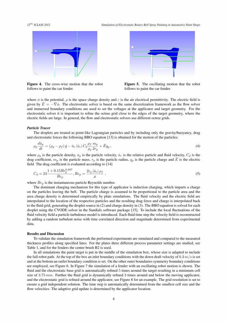
Figure 4. The cross-wise motion that the robotfollows to paint the car fender.
Figure 5. The oscillating motion that the robotfollows to paint the car fender.
where φ is the potential, ρ is the space charge density and ε is the air electrical permittivity. The electric field isgiven by E = −∇φ. The electrostatic solver is based on the same discretization framework as the flow solverand immersed boundary conditions are used to set the voltages at the applicator and target geometry. For theelectrostatic solver it is important to refine the octree grid close to the edges of the target geometry, where theelectric fields are large. In general, the flow and electrostatic solvers use different octree grids.
Particle TracerThe droplets are treated as point-like Lagrangian particles and by including only the gravity/buoyancy, drag
and electrostatic forces the following BBO equation [13] is obtained for the motion of the particles:
ρpdupdt
= (ρp − ρf ) g − ur |ur|Cdρfρp
mp
2rp+ Eqp , (4)
where ρp is the particle density, up is the particle velocity, ur is the relative particle and fluid velocity, Cd is thedrag coefficient, mp is the particle mass, rp is the particle radius, qp is the particle charge and E is the electricfield. The drag coefficient is evaluated according to [14]
Cd = 241 + 0.15Re0.687p
Rep, Rep =
2rp |ur| ρfµ
, (5)
where Rep is the instantaneous particle Reynolds number.The dominant charging mechanism for this type of applicator is induction charging, which imparts a charge
on the particles leaving the bell. The particle charge is assumed to be proportional to the particle area and thearea charge density is determined empirically by plate simulations. The fluid velocity and the electric field areinterpolated to the location of the respective particles and the resulting drag force and charge is interpolated backto the fluid grid, generating the droplet source in (2) and charge density in (3). The BBO equation is solved for eachdroplet using the CVODE solver in the Sundials software package [15]. To include the local fluctuations of thefluid velocity field a particle turbulence model is introduced. Each fluid time step the velocity field is reconstructedby adding a random turbulent noise with time correlated direction and magnitude determined from experimentaldata.
Results and DiscussionTo validate the simulation framework the performed experiments are simulated and compared to the measured
thickness profiles along specified lines. For the plates three different process parameter settings are studied, seeTable 1, and for the fenders the center brush B2 is used.
In all simulations the paint target is put in the middle of the simulation box, whose size is adapted to includethe full robot path. At the top of the box an inlet boundary conditions with the down draft velocity of 0.3m/s is setand at the bottom an outlet boundary condition is set. On the other outer boundaries symmetry boundary conditionsare employed, see Figure 6. In Figure 7 the simulation of a fender with an oscillating robot motion is shown. Thefluid and the electrostatic base grid is automatically refined 5 times around the target resulting in a minimum cellsize of 3.75mm. Further the fluid grid is dynamically refined 3 times around and below the moving applicator,and the electrostatic grid is refined around the applicator, see Figure 8 for an example. The grid resolution is set toensure a grid independent solution. The time step is automatically determined from the smallest cell size and theflow velocities. The adaptive grid update is determined by the applicator location.
4

12th ICLASS 2012 Simulation of Electrostatic Rotary Bell Spray Painting in Automotive Paint Shops
Figure 6. The simulation box with a Volvo V60fender in the middle, the full robot path and the posi-tions of the inlet, outlet and symmetry boundary con-ditions.
Figure 7. A snapshot of a paint simulation with anoscillating robot motion. The paint droplets are col-ored by the fluid velocity and the fender by the paintthickness.
Figure 8. A side view of the dynamic octree grids around the fender and the paint applicator. On the left the fluidgrid and on the right the electrostatic grid.
Plate simulationsThe horizontal and vertical plates (1000×150mm2) are simulated with the three different process parameters.
The robot speed is set to 200mm/s and TCP distance is set to 200mm. In Figure 9 a snapshot from the horizontalsimulation is shown. The paint thickness is visualized on the center test plate laying on a larger grounded plate(1000 × 1000mm2) to avoid electrostatic edge effects. The simulated thickness profiles for the different processparameters are compared to the experimental measurements in Figure 10. The simulations are in good agreementwith the experimental results. A simulation of the vertical plate is shown in Figure 11. In the figure it is noticedthat the paint is effected by the down draft and gravity, resulting in an asymmetric thickness profile. From thecomparison in Figure 12 it is concluded that the simulation accurately captures these effects.
Fender simulationsTo validate the simulation framework for a complex geometry a Volvo V60 fender is placed on a holder and
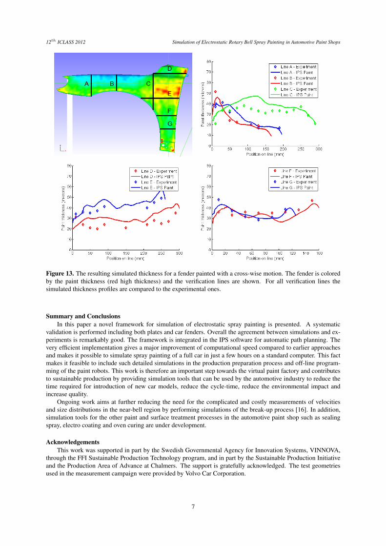
painted with a cross-wise and an oscillating robot motion, see Figures 4 and 5. The holder is also grounded and isimportant to include in the simulations as it has a significant effect on the electric field. For the fenders the robotvelocity was increased to 300mm/s. In Figure 13 the resulting simulated paint thickness for the fender paintedwith a cross-wise motion is shown. A large variation in paint thickness is observed over the fender. In general thethickness is largest close to the edges due to electrostatic effects. This is clearly seen along the A and B verificationlines. In the top right of the figure the experiments and the simulations are compared for these lines, showing thatthe simulated edge effects predict the measured ones in an accurate way. Further, in the area where the two strokesare overlapping the thickness is of course larger. Line D is placed in a concave area where the electrostatic effect
5

12th ICLASS 2012 Simulation of Electrostatic Rotary Bell Spray Painting in Automotive Paint Shops
Figure 9. Paint simulation on the horizontal plate,which is located on a larger grounded plate. The paintdroplets are colored by the fluid velocity and the tar-get plate by the paint thickness. Red indicates highvelocity and thickness.
Figure 10. Experimental and simulated thicknessprofiles for the horizontal plate.
Figure 11. Paint simulation on the vertical plate,which is located on a larger grounded plate. The paintdroplets are colored by the fluid velocity and the tar-get plate by the paint thickness. Red indicates highvelocity and thickness.
Figure 12. Experimental and simulated thicknessprofiles for the vertical plate.
should decrease the paint thickness instead of increasing it. In the lower left figure this assumption is verified byboth the simulation and the experiment. Other interesting locations on the fender are along the F and G lines thatare only effected by the vertical stroke but the paint thickness is still doubled compared to the B line, which isonly effected by the horizontal stroke. In the lower right of the figure this is shown for both the experiment andthe simulation. In the simulations the authors have noticed that when painting a vertical target with an upwardmotion the paint droplets that do not directly hit the target travel almost parallel to the target until they are finallydrawn towards it by the electrostatic effect. This is one reason for the fairly large paint thickness along the G linein the experiment and also captured by the simulation. The Volvo fender is also simulated with an oscillating robotmotion and the resulting thickness is shown in Figure 14. Due to the oscillating motion the thickness is smootherbut the edge effects are still present for almost all verification lines. The fender is a little bit bent along a linefrom the left edge towards the right. Along this virtual line the distance between the applicator and the target issmaller and a thicker paint thickness is noticed both in the simulation and the experiment. Further, in the middleof line E, where no edge effect is present, it is a clear dip in the resulting thickness for both the simulation andthe experiment. The figure also shows that the thickness along line D is small, only around 10µm. The effectof the electrostatic field in this concave region is even more pronounced for the oscillating motion compared tothe cross-wise motion. Overall the simulations manage to capture these large thickness fluctuations in an accurateway. To evaluate the paint thickness very close to the edges is difficult and the decay seen in the simulations isprobably due to how the thickness integration of the particle impacts is done, see [10] for a thorough discussion.
6
12th ICLASS 2012 Simulation of Electrostatic Rotary Bell Spray Painting in Automotive Paint Shops
Figure 13. The resulting simulated thickness for a fender painted with a cross-wise motion. The fender is coloredby the paint thickness (red high thickness) and the verification lines are shown. For all verification lines thesimulated thickness profiles are compared to the experimental ones.
Summary and ConclusionsIn this paper a novel framework for simulation of electrostatic spray painting is presented. A systematic
validation is performed including both plates and car fenders. Overall the agreement between simulations and ex-periments is remarkably good. The framework is integrated in the IPS software for automatic path planning. Thevery efficient implementation gives a major improvement of computational speed compared to earlier approachesand makes it possible to simulate spray painting of a full car in just a few hours on a standard computer. This factmakes it feasible to include such detailed simulations in the production preparation process and off-line program-ming of the paint robots. This work is therefore an important step towards the virtual paint factory and contributesto sustainable production by providing simulation tools that can be used by the automotive industry to reduce thetime required for introduction of new car models, reduce the cycle-time, reduce the environmental impact andincrease quality.
Ongoing work aims at further reducing the need for the complicated and costly measurements of velocitiesand size distributions in the near-bell region by performing simulations of the break-up process [16]. In addition,simulation tools for the other paint and surface treatment processes in the automotive paint shop such as sealingspray, electro coating and oven curing are under development.
AcknowledgementsThis work was supported in part by the Swedish Governmental Agency for Innovation Systems, VINNOVA,
through the FFI Sustainable Production Technology program, and in part by the Sustainable Production Initiativeand the Production Area of Advance at Chalmers. The support is gratefully acknowledged. The test geometriesused in the measurement campaign were provided by Volvo Car Corporation.
7

12th ICLASS 2012 Simulation of Electrostatic Rotary Bell Spray Painting in Automotive Paint Shops
Figure 14. The resulting simulated thickness for a fender painted with an oscillating motion. The fender is coloredby the paint thickness (red high thickness) and the verification lines are shown. For all verification lines thesimulated thickness profiles are compared to the experimental ones.
References[1] Ellwood, K. R. J., Braslaw, J., Journal of Electrostatics 45:1-23 (1998).[2] Im, K. -S., Lai, M. -C., Yu, S. -T. J., Matheson Jr, R. R., Journal of Fluids Engineering 126:449-456 (2004).[3] Huang H., Lai, M. -C., Meredith, W., Proc. 10th International KIVA Users Group Meeting, Detroit 2000.[4] Ye, Q., Shen, B., Tiedje, O., Domnick, J., Proc. 24th European Conference on Liquid Atomization and Spray
Systems, Estoril, Portugal, 2011.[5] Domnick, J., Scheibe, A., Ye, Q., Part. Part. Syst. Charact. 22:141-150 (2005).[6] Domnick, J., Scheibe, A., Ye, Q., Part. Part. Syst. Charact. 23:408-416 (2006).[7] Peskin, C., Journal of Computational Physics 25:220-252 (1977).[8] Mark, A., van Wachem, B. G. M., Journal of Computational Physics 227:6660-6680 (2008).[9] Mark, A., Rundqvist, R., Edelvik, F., Fluid Dynamics & Materials Processing 7-3:241-258 (2011).[10] Tafuri, S., Ekstedt, F., Carlson, J. S., Mark, A., Edelvik, F., Proc. of the ASME 2012 International Design En-
gineering Technical Conferences & Computers and Information in Engineering Conference, Chicago, USA,2012.
[11] van Doormaal, J. P., Raithby, G. D., Numerical Heat Transfer 7:147-163 (1984).[12] Rhie, C. M., Chow, W. L., AIAA J1 21:1527-1532 (1983).[13] Maxey, M. R., Riley, J. J., Physics of Fluids 26-4:883-889 (1983).[14] Schiller, L., Neumann, A., Verein Deutscher Ingenieure 77:318-320 (1933).[15] Hindmarsh, A. C., Brown, P. N., Grant, K. E., Lee, S. L., Serban, R., Shumaker, D. E., Woodward, C. S.,
ACM Transactions on Mathematical Software 31-3:363-396 (2005).[16] Andersson, B., Golovitchev V., Jakobsson, S., Mark, A., Edelvik, F., Davidson, L., Carlson, J. S., Proc. 12th
Triennial International Conference on Liquid Atomization and Spray Systems, Heidelberg, Germany, 2012.
8