Simulation in Metallurgical Processing: Recent...
7
Simulation in Metallurgical Processing: Recent Developments and Future Perspectives ANDREAS LUDWIG, 1,3,4 MENGHUAI WU, 2 and ABDELLAH KHARICHA 1 1.—Department of Metallurgy, Montanuniversitaet Leoben, Leoben, Austria. 2.—Christian- Doppler Laboratory for Advanced Process Simulation of Solidification and Melting, Department Metallurgy, Montanuniversitaet Leoben, Leoben, Austria. 3.—e-mail: [email protected]. 4.—e-mail: [email protected] This article briefly addresses the most important topics concerning numerical simulation of metallurgical processes, namely, multiphase issues (particle and bubble motion and flotation/sedimentation of equiaxed crystals during solidi- fication), multiphysics issues (electromagnetic stirring, electro-slag remelting, Cu-electro-refining, fluid–structure interaction, and mushy zone deformation), process simulations on graphical processing units, integrated computational materials engineering, and automatic optimization via simulation. The pre- sent state-of-the-art as well as requirements for future developments are presented and briefly discussed. INTRODUCTION Numerical process simulations are nowadays standard for designing and optimization of metal- lurgical processes. 1 Furnace construction, tundish planning, or designing of continuous casting machi- nes are assisted by the beforehand use of simulation tools. On the other hand, many metallurgical pro- cesses need multiphase and/or multiphysics descrip- tions to account for essential process details; yet, often these descriptions are missing or only roughly available. In this article, which is based on two former review reports by the same authors, 2,3 a short overview on present developments and future directions in the field is provided. MULTIPHASE SIMULATION Motion of Particles/Bubbles Understanding the behavior of nonmetallic inclu- sions (particles) or gas bubbles in molten steel is an important topic in primary and secondary metal- lurgy. 4 Examples are the gas bubble flow in steel- making vessels, melt stirring in ladles to maintain thermal homogeneity and reduce nonmetallic inclu- sions, melt flow and removal of nonmetallic inclu- sions in tundishes, blowing argon gas into submerged entry nozzle (SEN) during continuous casting to minimize the risk of clogging, etc. The most common way of modeling the motion of bubbles/particles in molten steel is the usage of the so-called disperse phase method (DPM). The turbulent flow of the molten steel can be obtained by solving the Navier– Stokes equation together with corresponding turbu- lence equations, while the trajectory of particles/ bubbles (or packets of particles/bubbles) are calcu- lated by solving Newton’s law for the motion of bubbles/particles considering their interaction with the turbulent melt flow. 5–8 The impact of bubbles on the transient, turbulent flow in a continuous caster for steel slabs 8 and bubble coagulation and breakup were also investigated by using this approach. 9 Recently, the current authors performed laboratory water-particle flow experiments to evaluate such a DPM model and discussed remarkable agreement between experiments and simulations. 10 Flotation/Sedimentation of Equiaxed Crystals During Solidification In practical casting processes, equiaxed crystals forming during solidification can move freely, either float or sediment, to form the as-cast structure. This kind of motion of crystals can cause significant structural and compositional heterogeneity, i.e., macrosegregation. To model the nucleation, growth, motion, and sedimentation of equiaxed crystals, a multiphase volume-average approach was pro- posed. 11,12 Different from the aforementioned DPM method, the equiaxed crystals are here treated as a JOM, Vol. 68, No. 8, 2016 DOI: 10.1007/s11837-016-1992-0 Ó 2016 The Author(s). This article is published with open access at Springerlink.com (Published online June 27, 2016) 2191
Transcript of Simulation in Metallurgical Processing: Recent...
Simulation in Metallurgical Processing: Recent Developmentsand Future Perspectives
ANDREAS LUDWIG,1,3,4 MENGHUAI WU,2 and ABDELLAH KHARICHA1
1.—Department of Metallurgy, Montanuniversitaet Leoben, Leoben, Austria. 2.—Christian-Doppler Laboratory for Advanced Process Simulation of Solidification and Melting, DepartmentMetallurgy, Montanuniversitaet Leoben, Leoben, Austria. 3.—e-mail: [email protected].—e-mail: [email protected]
This article briefly addresses the most important topics concerning numericalsimulation of metallurgical processes, namely, multiphase issues (particle andbubble motion and flotation/sedimentation of equiaxed crystals during solidi-fication), multiphysics issues (electromagnetic stirring, electro-slag remelting,Cu-electro-refining, fluid–structure interaction, and mushy zone deformation),process simulations on graphical processing units, integrated computationalmaterials engineering, and automatic optimization via simulation. The pre-sent state-of-the-art as well as requirements for future developments arepresented and briefly discussed.
INTRODUCTION
Numerical process simulations are nowadaysstandard for designing and optimization of metal-lurgical processes.1 Furnace construction, tundishplanning, or designing of continuous casting machi-nes are assisted by the beforehand use of simulationtools. On the other hand, many metallurgical pro-cesses need multiphase and/or multiphysics descrip-tions to account for essential process details; yet,often these descriptions are missing or only roughlyavailable. In this article, which is based on twoformer review reports by the same authors,2,3 ashort overview on present developments and futuredirections in the field is provided.
MULTIPHASE SIMULATION
Motion of Particles/Bubbles
Understanding the behavior of nonmetallic inclu-sions (particles) or gas bubbles in molten steel is animportant topic in primary and secondary metal-lurgy.4 Examples are the gas bubble flow in steel-making vessels, melt stirring in ladles to maintainthermal homogeneity and reduce nonmetallic inclu-sions, melt flow and removal of nonmetallic inclu-sions in tundishes, blowing argon gas into submergedentry nozzle (SEN) during continuous casting tominimize the risk of clogging, etc. The most commonway of modeling the motion of bubbles/particles in
molten steel is the usage of the so-called dispersephase method (DPM). The turbulent flow of themolten steel can be obtained by solving the Navier–Stokes equation together with corresponding turbu-lence equations, while the trajectory of particles/bubbles (or packets of particles/bubbles) are calcu-lated by solving Newton’s law for the motion ofbubbles/particles considering their interaction withthe turbulent melt flow.5–8 The impact of bubbles onthe transient, turbulent flow in a continuous casterfor steel slabs8 and bubble coagulation and breakupwere also investigated by using this approach.9
Recently, the current authors performed laboratorywater-particle flow experiments to evaluate such aDPM model and discussed remarkable agreementbetween experiments and simulations.10
Flotation/Sedimentation of Equiaxed CrystalsDuring Solidification
In practical casting processes, equiaxed crystalsforming during solidification can move freely, eitherfloat or sediment, to form the as-cast structure. Thiskind of motion of crystals can cause significantstructural and compositional heterogeneity, i.e.,macrosegregation. To model the nucleation, growth,motion, and sedimentation of equiaxed crystals, amultiphase volume-average approach was pro-posed.11,12 Different from the aforementioned DPMmethod, the equiaxed crystals are here treated as a
JOM, Vol. 68, No. 8, 2016
DOI: 10.1007/s11837-016-1992-0� 2016 The Author(s). This article is published with open access at Springerlink.com
(Published online June 27, 2016) 2191
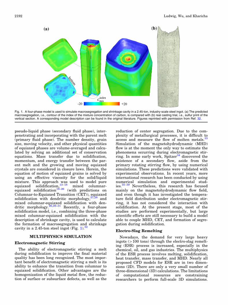
pseudo-liquid phase (secondary fluid phase), inter-penetrating and incorporating with the parent melt(primary fluid phase). The number density, grainsize, moving velocity, and other physical quantitiesof equiaxed phases are volume-averaged and calcu-lated by solving an additional set of conservationequations. Mass transfer due to solidification,momentum, and energy transfer between the par-ent melt and the growing and moving equiaxedcrystals are considered in closure laws. Herein, theequation of motion of equiaxed grains is solved byusing an effective viscosity for the solid/liquidmixture. This approach was used to model pureequiaxed solidification,13–18 mixed columnar-equiaxed solidification19–26 (with predictions onColumnar-to-Equiaxed Transition (CET)), equiaxedsolidification with dendritic morphology,27,28 andmixed columnar-equiaxed solidification with den-dritic morphology.26,29–31 Recently, a four-phasesolidification model, i.e., combining the three-phasemixed columnar-equiaxed solidification with thedescription of shrinkage cavity, is used to calculatethe formation of macrosegregation and shrinkagecavity in a 2.45-ton steel ingot (Fig. 1).32
MULTIPHYSICS SIMULATION
Electromagnetic Stirring
The ability of electromagnetic stirring a meltduring solidification to improve the final materialquality has been long recognized. The most impor-tant benefit of electromagnetic stirring a melt is itsability to enhance the transition from columnar toequiaxed solidification. Other advantages are thehomogenization of the liquid metal flow, the reduc-tion of surface or subsurface defects, as well as the
reduction of center segregation. Due to the com-plexity of metallurgical processes, it is difficult toaccess and measure the flow of molten metals.33
Simulation of the magnetohydrodynamic (MHD)flow is at the moment the only way to estimate thephenomena occurring during electromagnetic stir-ring. In some early work, Spitzer34 discovered theexistence of a secondary flow, aside from theprimary rotating stirring flow, by using numericalsimulations. These predictions were validated withexperimental observations. In recent years, moreinternational research has been conducted by usingnumerical simulation and experimental stud-ies.35–39 Nevertheless, this research has focusedmainly on the magnetohydrodymamic flow field,and even though it has investigated the tempera-ture field distribution under electromagnetic stir-ring, it has not considered the interaction withsolidification. At the present stage, most of thestudies are performed experimentally, but largescientific efforts are still necessary to build a modelable to couple MHD, CET, and formation of segre-gation during solidification.
Electro-Slag Remelting
Nowadays, the demand for very large heavyingots (>100 tons) through the electro-slag remelt-ing (ESR) process is increased, especially in thechemical, oil, and gas industries. The multiphysicsof the ESR process involves melting, solidification,heat transfer, mass transfer, and MHD. Nearly allproposed CFD models for ESR are in two dimen-sions (2D). There are only a very small number ofthree-dimensional (3D) calculations. The limitationsof computational resources are constrainingresearchers to perform full-scale 3D simulations.
Fig. 1. A four-phase model is used to simulate macrosegregation and shrinkage cavity in a 2.45-ton, industry-scale steel ingot. (a) The predictedmacrosegregation, i.e., contour of the index of the mixture concentration of carbon, is compared with (b) real casting trial, i.e., sulfur print of thevertical section. A corresponding model description can be found in the original literature. Figures reprinted with permission from Ref. 32.
Ludwig, Wu, and Kharicha2192
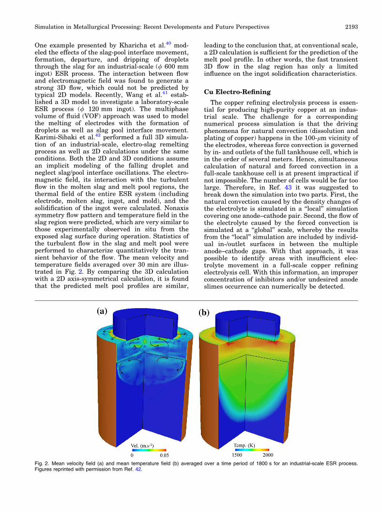
One example presented by Kharicha et al.40 mod-eled the effects of the slag-pool interface movement,formation, departure, and dripping of dropletsthrough the slag for an industrial-scale (/ 600 mmingot) ESR process. The interaction between flowand electromagnetic field was found to generate astrong 3D flow, which could not be predicted bytypical 2D models. Recently, Wang et al.41 estab-lished a 3D model to investigate a laboratory-scaleESR process (/ 120 mm ingot). The multiphasevolume of fluid (VOF) approach was used to modelthe melting of electrodes with the formation ofdroplets as well as slag pool interface movement.Karimi-Sibaki et al.42 performed a full 3D simula-tion of an industrial-scale, electro-slag remeltingprocess as well as 2D calculations under the sameconditions. Both the 2D and 3D conditions assumean implicit modeling of the falling droplet andneglect slag/pool interface oscillations. The electro-magnetic field, its interaction with the turbulentflow in the molten slag and melt pool regions, thethermal field of the entire ESR system (includingelectrode, molten slag, ingot, and mold), and thesolidification of the ingot were calculated. Nonaxissymmetry flow pattern and temperature field in theslag region were predicted, which are very similar tothose experimentally observed in situ from theexposed slag surface during operation. Statistics ofthe turbulent flow in the slag and melt pool wereperformed to characterize quantitatively the tran-sient behavior of the flow. The mean velocity andtemperature fields averaged over 30 min are illus-trated in Fig. 2. By comparing the 3D calculationwith a 2D axis-symmetrical calculation, it is foundthat the predicted melt pool profiles are similar,
leading to the conclusion that, at conventional scale,a 2D calculation is sufficient for the prediction of themelt pool profile. In other words, the fast transient3D flow in the slag region has only a limitedinfluence on the ingot solidification characteristics.
Cu Electro-Refining
The copper refining electrolysis process is essen-tial for producing high-purity copper at an indus-trial scale. The challenge for a correspondingnumerical process simulation is that the drivingphenomena for natural convection (dissolution andplating of copper) happens in the 100-lm vicinity ofthe electrodes, whereas force convection is governedby in- and outlets of the full tankhouse cell, which isin the order of several meters. Hence, simultaneouscalculation of natural and forced convection in afull-scale tankhouse cell is at present impractical ifnot impossible. The number of cells would be far toolarge. Therefore, in Ref. 43 it was suggested tobreak down the simulation into two parts. First, thenatural convection caused by the density changes ofthe electrolyte is simulated in a ‘‘local’’ simulationcovering one anode–cathode pair. Second, the flow ofthe electrolyte caused by the forced convection issimulated at a ‘‘global’’ scale, whereby the resultsfrom the ‘‘local’’ simulation are included by individ-ual in-/outlet surfaces in between the multipleanode–cathode gaps. With that approach, it waspossible to identify areas with insufficient elec-trolyte movement in a full-scale copper refiningelectrolysis cell. With this information, an improperconcentration of inhibitors and/or undesired anodeslimes occurrence can numerically be detected.
Fig. 2. Mean velocity field (a) and mean temperature field (b) averaged over a time period of 1800 s for an industrial-scale ESR process.Figures reprinted with permission from Ref. 42.
Simulation in Metallurgical Processing: Recent Developments and Future Perspectives 2193
Fluid–Structure Interaction
Solidification involves both fluid dynamic andstructure mechanical issues. The classic term offluid–structure interaction is mostly used for prob-lems where a fluid and a solid body exchangemomentum by the deformation of a predefinedinterface. Describing the fluid flow is a typicalcomputational fluid dynamics (CFD) problem,whereas describing the deformation of the soliddomain is a typical finite element method (FEM)problem. The interplay of CFD and FEM happensvia the interface between the fluid and mechanicaldomains. The state-of-the-art solution to this issueis to couple both CFD-based and FEM-based codesby considering data transfer at the domain inter-face.44,45 Of course, the two domains must be re-meshed consistently. Unfortunately, this solutioncannot be used directly for the solidification becausethe interface between the fluid domain (liquid melt)and the mechanical domain (solidified region includ-ing mushy zone) is not pre-describable. A monolithicformulation treating the fluid–structure interactionsounds like a better alternative,46 but it is still notapplicable for solidification as the differencebetween liquid viscosity and the solid consistencyis huge. Therefore, Bellet et al. suggested a parti-tioned formulation to treat this issue47 with thesolidifying mushy zone as part of the solution. Thispartitioned formulation has been used to calculate
the solidification of an ingot casting with theconsideration of the deforming solid shell. This topicis still in its infant stage, and it is subject to furtherdevelopment.
Mushy Zone Deformation
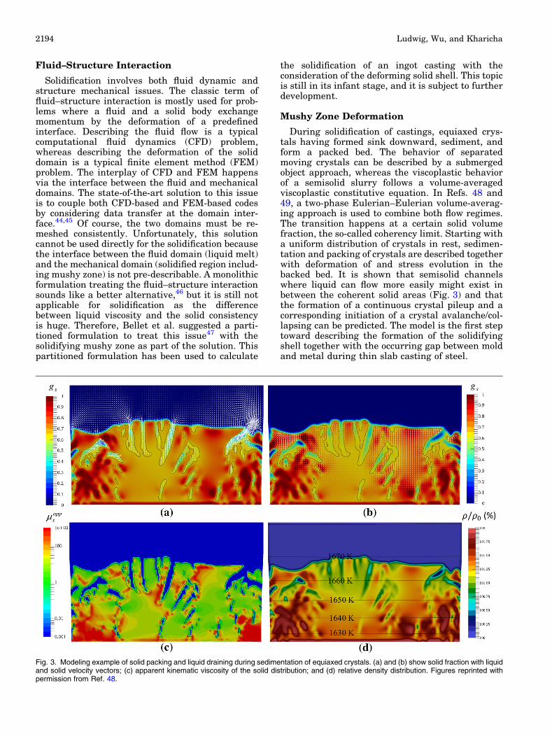
During solidification of castings, equiaxed crys-tals having formed sink downward, sediment, andform a packed bed. The behavior of separatedmoving crystals can be described by a submergedobject approach, whereas the viscoplastic behaviorof a semisolid slurry follows a volume-averagedviscoplastic constitutive equation. In Refs. 48 and49, a two-phase Eulerian–Eulerian volume-averag-ing approach is used to combine both flow regimes.The transition happens at a certain solid volumefraction, the so-called coherency limit. Starting witha uniform distribution of crystals in rest, sedimen-tation and packing of crystals are described togetherwith deformation of and stress evolution in thebacked bed. It is shown that semisolid channelswhere liquid can flow more easily might exist inbetween the coherent solid areas (Fig. 3) and thatthe formation of a continuous crystal pileup and acorresponding initiation of a crystal avalanche/col-lapsing can be predicted. The model is the first steptoward describing the formation of the solidifyingshell together with the occurring gap between moldand metal during thin slab casting of steel.
Fig. 3. Modeling example of solid packing and liquid draining during sedimentation of equiaxed crystals. (a) and (b) show solid fraction with liquidand solid velocity vectors; (c) apparent kinematic viscosity of the solid distribution; and (d) relative density distribution. Figures reprinted withpermission from Ref. 48.
Ludwig, Wu, and Kharicha2194
PROCESS SIMULATIONS ON GPUS
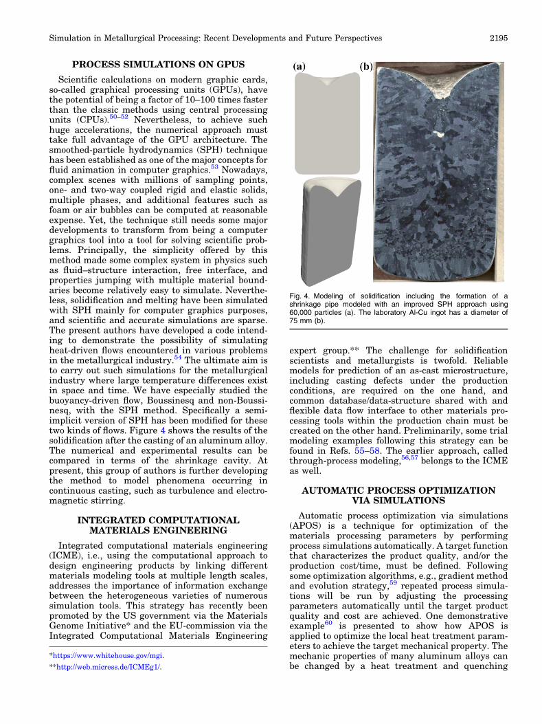
Scientific calculations on modern graphic cards,so-called graphical processing units (GPUs), havethe potential of being a factor of 10–100 times fasterthan the classic methods using central processingunits (CPUs).50–52 Nevertheless, to achieve suchhuge accelerations, the numerical approach musttake full advantage of the GPU architecture. Thesmoothed-particle hydrodynamics (SPH) techniquehas been established as one of the major concepts forfluid animation in computer graphics.53 Nowadays,complex scenes with millions of sampling points,one- and two-way coupled rigid and elastic solids,multiple phases, and additional features such asfoam or air bubbles can be computed at reasonableexpense. Yet, the technique still needs some majordevelopments to transform from being a computergraphics tool into a tool for solving scientific prob-lems. Principally, the simplicity offered by thismethod made some complex system in physics suchas fluid–structure interaction, free interface, andproperties jumping with multiple material bound-aries become relatively easy to simulate. Neverthe-less, solidification and melting have been simulatedwith SPH mainly for computer graphics purposes,and scientific and accurate simulations are sparse.The present authors have developed a code intend-ing to demonstrate the possibility of simulatingheat-driven flows encountered in various problemsin the metallurgical industry.54 The ultimate aim isto carry out such simulations for the metallurgicalindustry where large temperature differences existin space and time. We have especially studied thebuoyancy-driven flow, Boussinesq and non-Boussi-nesq, with the SPH method. Specifically a semi-implicit version of SPH has been modified for thesetwo kinds of flows. Figure 4 shows the results of thesolidification after the casting of an aluminum alloy.The numerical and experimental results can becompared in terms of the shrinkage cavity. Atpresent, this group of authors is further developingthe method to model phenomena occurring incontinuous casting, such as turbulence and electro-magnetic stirring.
INTEGRATED COMPUTATIONALMATERIALS ENGINEERING
Integrated computational materials engineering(ICME), i.e., using the computational approach todesign engineering products by linking differentmaterials modeling tools at multiple length scales,addresses the importance of information exchangebetween the heterogeneous varieties of numeroussimulation tools. This strategy has recently beenpromoted by the US government via the MaterialsGenome Initiative* and the EU-commission via theIntegrated Computational Materials Engineering
expert group.** The challenge for solidificationscientists and metallurgists is twofold. Reliablemodels for prediction of an as-cast microstructure,including casting defects under the productionconditions, are required on the one hand, andcommon database/data-structure shared with andflexible data flow interface to other materials pro-cessing tools within the production chain must becreated on the other hand. Preliminarily, some trialmodeling examples following this strategy can befound in Refs. 55–58. The earlier approach, calledthrough-process modeling,56,57 belongs to the ICMEas well.
AUTOMATIC PROCESS OPTIMIZATIONVIA SIMULATIONS
Automatic process optimization via simulations(APOS) is a technique for optimization of thematerials processing parameters by performingprocess simulations automatically. A target functionthat characterizes the product quality, and/or theproduction cost/time, must be defined. Followingsome optimization algorithms, e.g., gradient methodand evolution strategy,59 repeated process simula-tions will be run by adjusting the processingparameters automatically until the target productquality and cost are achieved. One demonstrativeexample60 is presented to show how APOS isapplied to optimize the local heat treatment param-eters to achieve the target mechanical property. Themechanic properties of many aluminum alloys canbe changed by a heat treatment and quenching
Fig. 4. Modeling of solidification including the formation of ashrinkage pipe modeled with an improved SPH approach using60,000 particles (a). The laboratory Al-Cu ingot has a diameter of75 mm (b).
*https://www.whitehouse.gov/mgi.
**http://web.micress.de/ICMEg1/.
Simulation in Metallurgical Processing: Recent Developments and Future Perspectives 2195
procedure. If locally a strengthening of the alloy isneeded, a localized heat treatment and quenchingprocedure may be an alternative to the energy-intensive and costly treatment of the whole part.Nevertheless, it is not clear which process param-eters are required to achieve the desired localstrengthening. Therefore, the optimizationscheme performs a series of process simulationswhere LASER power, beam diameter, and exposuretime are varied automatically until the energyminimized process is found that ensures sufficientlocal strengthening of the alloy.
CONCLUSION AND SUMMARY
Process simulations for metallurgical processeshave become a daily routine for engineers workingin industry. Yet, many processes are multiphaseand multiphysics in nature. Considering corre-sponding phenomena in detail is soon bringing thestandard simulation tools to the edge of theirability. In the next decades, the following is greatlyneeded: (I) new, more sophistic model considera-tions; (II) new/improved software strategies thatmight save most of the computation efforts; and (III)companies willing to take the effort to verifynumerical predictions by measuring process detailseven during their production.
ACKNOWLEDGEMENTS
Open access funding provided by Montanuniver-sitat Leoben. The authors are grateful for financialsupport from RHI Technologies, INTECO specialmelting technologies GmbH, Atlantic Copper, AurubisAG, Aurubis Belgium, Boliden Mineral, KennecottUtah Copper, Montanwerke Brixlegg, and OutotecFinland. Also, part of this work was financial sup-ported by the Christian-Doppler Society and theAustrian Federal Government (in particular by theBundesministerium fur Verkehr, Innovation undTechnologie, and the Bundesministerium fur Wirt-schaft, Familie und Jugend) and the Styrian Provin-cial Governments, represented by OsterreichischeForschungsforderungsgesellschaft mbH and by Steir-ische Wirtschaftsforderungsgesellschaft mbH, withinthe research activities of the K2 Competence Centreon ‘‘Integrated Research in Materials, Processing andProduct Engineering,’’ operated by the MaterialsCenter Leoben Forschung GmbH in the framework ofthe Austrian COMET Competence Centre Pro-gramme, for which the authors are grateful.
OPEN ACCESS
This article is distributed under the terms of theCreative Commons Attribution 4.0 InternationalLicense (http://creativecommons.org/licenses/by/4.0/), which permits unrestricted use, distribution, andreproduction in any medium, provided you giveappropriate credit to the original author(s) and the
source, provide a link to the Creative Commonslicense, and indicate if changes were made.
REFERENCES
1. M. Rappaz, M. Bellet, and M. Deville, Numerical Modelling inMaterialsScienceandEngineering (NewYork:Springer,1998).
2. A. Ludwig, A. Kharicha, and M. Wu, Metall. Mater. Trans.B 45, 36 (2013).
3. A. Ludwig, M. Wu, A. Kharicha, A. Vakhrushev, J. Boha-cek, A. Kemminger, and E. Karimi-Sibaki, BHM BergHuettenmaenn. Monatsh. 158, 184 (2013).
4. R.I.L. Guthrie, Metall. Mater. Trans. B 35, 417 (2004).5. C. Pfeiler, M. Wu, and A. Ludwig, Mater. Sci. Eng., A 413–
414, 115 (2005).6. C. Pfeiler, M. Wu, A. Ludwig, C. Chimani, and J. Watzin-
ger, 6th International Conference Model. Cast. Weld. Adv.Solidif. Process. (MCWASP VI), eds. C.-A. Gandin and M.Bellet (Opio; TMS Publication, 2006).
7. C. Pfeiler, B.G.G. Thomas, M. Wu, A. Ludwig, and A.Kharicha, Steel Res. Int. 79, 599 (2008).
8. Z.Q.Q. Liu, B.K.K. Li, and M.F.F. Jiang, Metall. Mater.Trans. B 45, 675 (2013).
9. T. Zhang, Z.G. Luo, C.L. Liu, H. Zhou, and Z.S. Zou,Powder Technol. 273, 154 (2015).
10. A. Vakhrushev, M. Wu, A. Ludwig, G. Nitzl, Y. Tang, and G.Hackl,5thInternationalConferenceSimul.Model.Met.Process.Steelmak. (STEELSIM 2013) (Ostrova, Czech Republic, 2013).
11. J. Ni and C. Beckermann, Metall. Trans. B 22, 349 (1991).12. C. Beckermann and R. Viskanta,Appl.Mech.Rev.46, 1 (1993).13. A. Ludwig and M. Wu, Metall. Mater. Trans. A 33, 3673
(2002).14. M. Wu, A. Ludwig, A. Buhrig-Polaczek, M. Fehlbier, and
P.R. Sahm, Int. J. Heat Mass Transf. 46, 2819 (2003).15. M. Wu and A. Ludwig, Mater. Sci. Eng. A 413–414, 192
(2005).16. M. Wu, A. Ludwig, and J. Luo, Mater. Sci. Forum 475–479,
2725 (2005).17. M. Wu, A. Ludwig, and L. Ratke, Model. Simul. Mater.
0393, 755 (2003).18. T.M. Wang, S. Yao, X.G. Zhang, J.Z. Jin, M. Wu, A. Lud-
wig, B. Pustal, and A. Buhrig-Polaczek, Acta Metall. Sin.42, 584 (2006).
19. A. Ludwig and M. Wu, Mater. Sci. Eng. A 413–414, 109(2005).
20. A. Ludwig, M. Gruber-Pretzler, F. Mayer, A. Ishmurzin,and M. Wu, Mater. Sci. Eng. A 413–414, 485 (2005).
21. M. Wu and A. Ludwig, Metall.Mater. Trans. A 37, 1613 (2006).22. M. Wu and A. Ludwig, Metall. Mater. Trans. A 38, 1465
(2007).23. M. Wu, L. Konozsy, A. Ludwig, W. Schutzenhofer, and R.
Tanzer, Steel Res. Int. 79, 637 (2008).24. M. Wu, J. Li, A. Ludwig, and A. Kharicha, Comp. Mater.
Sci. 79, 830 (2013).25. M. Wu, J. Li, A. Ludwig, and A. Kharicha, Comp. Mater.
Sci. 92, 267 (2014).26. M. Ahmadein, M. Wu, and A. Ludwig, J. Cryst. Growth
417, 65 (2015).27. M. Wu and A. Ludwig, Acta Mater. 57, 5621 (2009).28. M. Wu and A. Ludwig, Acta Mater. 57, 5632 (2009).29. M. Wu, A. Fjeld, and A. Ludwig, Comp. Mater. Sci. 50, 32
(2010).30. M. Wu, A. Ludwig, and A. Fjeld, Comp. Mater. Sci. 50, 43
(2010).31. M. Ahmadein, M. Wu, J.H.H. Li, P. Schumacher, and A.
Ludwig, Metall. Mater. Trans. A 44, 2895 (2013).32. M. Wu, A. Kharicha, A. Ludwig, and I.O.P. Conf, Ser.
Mater. Sci. Eng. 84, 012006 (2015).33. F. Stefani, T. Gundrum, and G. Gerbeth, Phys. Rev. E 70,
056306 (2004).34. K.H. Spitzer, M. Dubke, and K. Schwerdtfeger, Metall.
Trans. B 17, 119 (1986).
Ludwig, Wu, and Kharicha2196
35. K. Okazawa, T. Toh, J. Fukuda, T. Kawase, and M. Toki,ISIJ Int. 41, 851 (2001).
36. L.B. Trindade, A.C. Vilela, M.T. Vilhena, and R.B. Soares,IEEE Trans. Magn. 38, 3658 (2002).
37. F.C. Chang, J.R. Hull, and L. Beitelman, Metall. Mater.Trans. B 35, 1129 (2004).
38. M. Barna, B. Willers, J. Reiter, and S. Eckert, 2nd METECESTAD Conference (2015), pp. 6–2015.
39. M. Javurek, M. Barna, P. Gittler, K. Rockenschaub, and M.Lechner, Steel Res. Int. 79, 617 (2008).
40. A. Kharicha, A. Ludwig, and M. Wu, 8th InternationalPamir Conference Fund. Appl. MHD (Borgo France, 2011),pp. 695–699.
41. Q. Wang, Z. He, B. Li, and F. Tsukihashi, Metall. Mater.Trans. B 45, 2425 (2014).
42. E. Karimi-Sibaki, A. Kharicha, J. Bohacek, M. Wu, and A.Ludwig, Adv. Eng. Mater. 18, 224 (2015).
43. A. Kemminger and A. Ludwig, Eur. Metall. Conf. (Weimar,Germany, 2013), pp. 795–805.
44. H. Jasak and Z. Tukovic, Eur. Conf. Comput. Fluid Dyn. 1(2010).
45. G. Papadakis, J. Comp. Phys. 227, 3383 (2008).46. B. Hubner, E. Walhorn, and D. Dinkler, Comput. Methods
Appl. Mech. Eng. 193, 2087 (2004).47. O. Boughanmi and M. Bellet, Steelsim 2011, 1–10 (2011).48. A. Ludwig, A. Vakhrushev, T. Holzmann, M. Wu, and A.
Kharicha, I.O.P. Conf. Ser. Mater. Sci. Eng. 84, 012102 (2015).
49. A. Ludwig, A. Vakhrushev, M. Wu, T. Holzmann, and A.Kharicha, Trans. Indian Inst. Metall. 68, 1087 (2015).
50. E. Elsen, P. LeGresley, and E. Darve, J. Comput. Phys.227, 10148 (2008).
51. D. Goddeke, S.H.M. Buijssen, H. Wobker, and S. Turek,High Perform. Comput. Simul., eds. W.W. Smari and J.McIntire (2009), pp. 12–21.
52. A. Klockner, T. Warburton, J. Bridge, and J.S. Hesthaven,J. Comp. Phys. 228, 7863 (2009).
53. M. Ihmsen, J. Orthmann, B. Solenthaler, A. Kolb, and M.Teschner, Eurographics 2014, 21 (2014).
54. A. Kharicha, S. Baig, M. Wu, and A. Ludwig, To be publ.55. A. Ludwig, G. Unterreiter, M. Wu, B. Stauder, R. Tatschl,
W. Edelbauer, R. Kopun, B. Basara, D. Zhang, C. Som-mitsch, and F. Krumphals, 1st Int. Work. Softw. Solut.Integr. Comp. Mater. Eng. (2014), p. 82.
56. P. Li, D.M.M. Maijer, T.C.C. Lindley, and P.D.D. Lee,Mater. Sci. Eng. A 460–461, 20 (2007).
57. D.M. Maijer, Y.X. Gao, P.D. Lee, T.C. Lindley, and T. Fu-kui, Metall. Mater. Trans. A 35, 3275 (2004).
58. M.C. Schneider, J.C. Sturm, W. Schaefer, E. Hepp, and V.Gurevich, I.O.P. Conf. Ser. Mater. Sci. Eng. 84, 012035(2015).
59. N. Hofmann, S. Oliver, G. Laschet, F. Hediger, J. Wolf, andP.R. Sahm, Model. Simul. Mater. Eng. 5, 23 (1997).
60. T. Holzmann and A. Ludwig, IOP Conf. Ser. Mater. Sci.Eng. 119, 0120 (2016).
Simulation in Metallurgical Processing: Recent Developments and Future Perspectives 2197