Simulation Based Engineering & Sciences - EnginSoft - … · 41 Highlights on new ANSYS Release...
35
Newsletter Simulation Based Engineering & Sciences Year n°3 Autumn 2016 13 Nautilus tech by Faber The new frontier for hoods ventilation On the application of numerical analyses to hydropower plant design Dynamic response of a buried pipeline, under the action of the fall of rocks on the soil High Quality Printing with CFD Virtual Drop Test and Falling Object Test on Safety Remote Control On the application of numerical analyses to hydropower plant design Packaging Optimization driven by parametric morphing: development of an automatic methodology
-
Upload
truongtruc -
Category
Documents
-
view
218 -
download
0
Transcript of Simulation Based Engineering & Sciences - EnginSoft - … · 41 Highlights on new ANSYS Release...

NewsletterSimulation Based Engineering & Sciences
Year n°3 Autumn 201613
Nautilus tech by FaberThe new frontier for hoods ventilation
On the application of numerical analyses to hydropower plant design
Dynamic response of a buried pipeline, under the action of the fall of rocks on the soil
High Quality Printing with CFD
Virtual Drop Test and Falling ObjectTest on Safety Remote Control
On the application of numerical analyses to hydropower plant design
Packaging Optimizationdriven by parametric morphing:
development of an automatic methodology
3 - Newsletter EnginSoft Year 13 n°3 Flash
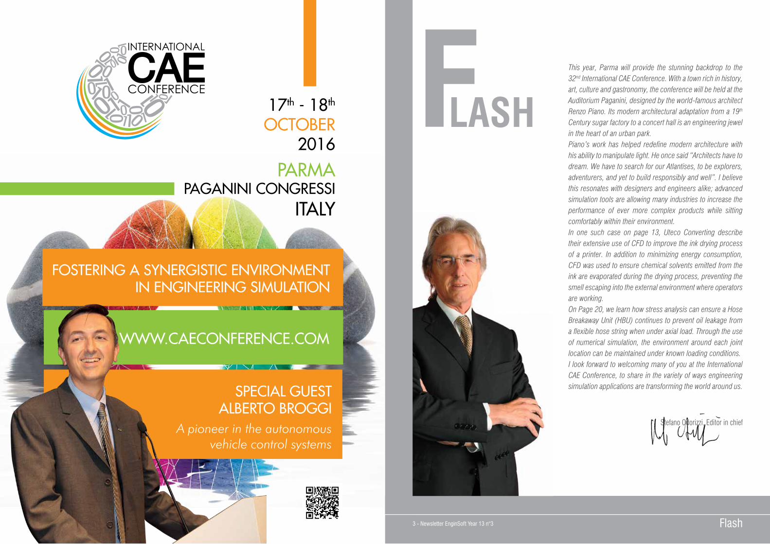
LASHThis year, Parma will provide the stunning backdrop to the 32nd International CAE Conference. With a town rich in history, art, culture and gastronomy, the conference will be held at the Auditorium Paganini, designed by the world-famous architect Renzo Piano. Its modern architectural adaptation from a 19th Century sugar factory to a concert hall is an engineering jewel in the heart of an urban park. Piano’s work has helped redefine modern architecture with his ability to manipulate light. He once said “Architects have to dream. We have to search for our Atlantises, to be explorers, adventurers, and yet to build responsibly and well”. I believe this resonates with designers and engineers alike; advanced simulation tools are allowing many industries to increase the performance of ever more complex products while sitting comfortably within their environment. In one such case on page 13, Uteco Converting describe their extensive use of CFD to improve the ink drying process of a printer. In addition to minimizing energy consumption, CFD was used to ensure chemical solvents emitted from the ink are evaporated during the drying process, preventing the smell escaping into the external environment where operators are working. On Page 20, we learn how stress analysis can ensure a Hose Breakaway Unit (HBU) continues to prevent oil leakage from a flexible hose string when under axial load. Through the use of numerical simulation, the environment around each joint location can be maintained under known loading conditions.I look forward to welcoming many of you at the International CAE Conference, to share in the variety of ways engineering simulation applications are transforming the world around us.
Stefano Odorizzi, Editor in chief
F17th - 18th
OCTOBER2016
PARMAPAGANINI CONGRESSI
ITALY
SPECIAL GUESTALBERTO BROGGI
A pioneer in the autonomous vehicle control systems
WWW.CAECONFERENCE.COM
FOSTERING A SYNERGISTIC ENVIRONMENTIN ENGINEERING SIMULATION
Newsletter EnginSoft Year 13 n°3 - 4 ContentsContents 5 - Newsletter EnginSoft Year 13 n°3
ContentsINTERVIEW6 The value of simulation as innovative component for high technology product development in advanced research for nuclear physics CASE HISTORIES8 Nautilus tech by Faber Spa - The new frontier for hoods ventilation10 Dynamic response of a buried pipeline, under the action of the fall of rocks on the soil13 High Quality Printing with CFD16 On the application of numerical analyses to hydropower plant design19 Virtual Drop Test and Falling Object Test on Safety Remote Control23 Innovative control and real-time quality prediction for the casting production of aluminum alloy structural components26 BOMAG uses DEM (Discrete Element Method) to analyze particulate behavior in their asphalt plant equipment28 Cooling simulation in continuous casting process of steel30 Simulation and validation of industrial uranium enrichment plant model32 Packaging Optimization driven by parametric morphing: development of an automatic methodology
36 Simulation of Large Compression Plants Transients39 The Role of Materials in Simulation Driven Product Development
SOFTWARE UPDATE41 Highlights on new ANSYS Release 17.242 ANSYS Fluent R17.244 ANSYS Maxwell 17.246 The EnginSoft High Frequency Electromagnetic side49 modeFRONTIER and ANSYS HPC Parametric Pack for highly Efficient Design Optimization for automotive applications52 Optimizing your Design for Manufacturing54 Practical examples of processes/products improvements thanks to simulation58 Recurdyn’s Premium Contact Technology62 MapleTM: From Concept to Deployment Maplesoft Engineering Solutions team helps FLSmidth develop revolutionary mining equipment
HARDWARE UPDATE64 How to choose the optimized hardware for HPC
OUR ACKNOWLEDGEMENT AND THANKS TO ALL THE COMPANIES, UNIVERSITIES AND RESEARCH CENTRES THAT HAVE CONTRIBUTED TO THIS ISSUE OF OUR NEWSLETTER
Newsletter EnginSoftYear 13 n°3 - Autumn 2016To receive a free copy of the next EnginSoft Newsletters, please contact our Marketing office at: [email protected]
All pictures are protected by copyright. Any reproduction of these pictures in any media and by any means is forbidden unless written authorization by EnginSoft has been obtained beforehand. ©Copyright EnginSoft Newsletter.
EnginSoft S.p.A.24126 BERGAMO c/o Parco Scientifico TecnologicoKilometro Rosso - Edificio A1, Via Stezzano 87Tel. +39 035 368711 • Fax +39 0461 97921550127 FIRENZE Via Panciatichi, 40Tel. +39 055 4376113 • Fax +39 0461 97921635129 PADOVA Via Giambellino, 7Tel. +39 049 7705311 • Fax +39 0461 97921772023 MESAGNE (BRINDISI) Via A. Murri, 2 - Z.I.Tel. +39 0831 730194 • Fax +39 0461 97922438123 TRENTO fraz. Mattarello - Via della Stazione, 27Tel. +39 0461 915391 • Fax +39 0461 97920110133 TORINO Corso Marconi, 10Tel. +39 011 6525211 • Fax +39 0461 979218
www.enginsoft.it - www.enginsoft.come-mail: [email protected]
The EnginSoft Newsletter is a quarterly magazine published by EnginSoft SpA
COMPANY INTERESTSEnginSoft GmbH - GermanyEnginSoft UK - United KingdomEnginSoft France - FranceEnginSoft Nordic - SwedenEnginSoft Turkey - TurkeyVSA-TTC3 - Germanywww.enginsoft.com
CONSORZIO TCN www.consorziotcn.it • www.improve.itCascade Technologies www.cascadetechnologies.comReactive Search www.reactive-search.comSimNumerica www.simnumerica.itM3E Mathematical Methods and Models for Engineering www.m3eweb.it
ASSOCIATION INTERESTSNAFEMS International www.nafems.it • www.nafems.orgTechNet Alliance www.technet-alliance.com
ADVERTISEMENT For advertising opportunities, please contact our Marketing office at: [email protected]
RESPONSIBLE DIRECTORStefano Odorizzi - [email protected]
ART DIRECTORLuisa Cunico - [email protected]
PRINTING Grafiche Dal Piaz - Trento
Auto
rizza
zione
del
Trib
unal
e di
Tre
nto
n° 1
353
RS d
i dat
a 2/
4/20
08
The EnginSoft Newsletter editions contain references to the following products which are trademarks or registered trademarks of their respective owners: ANSYS, ANSYS Workbench, AUTODYN, CFX, FLUENT, FORTE’, SpaceClaim and any and all ANSYS, Inc. brand, product, service and feature names, logos and slogans are registered trademarks or trademarks of ANSYS, Inc. or its subsidiaries in the United States or other countries. [ICEM CFD is a trademark used by ANSYS, Inc. under license]. (www.ANSYS.com) - modeFRONTIER is a trademark of ESTECO Spa (www.esteco.com) - Flowmaster is a registered trademark of Mentor Graphics in the USA (www.flowmaster.com) - MAGMASOFT is a trademark of MAGMA GmbH (www.magmasoft.de) - FORGE, COLDFORM and FORGE Nxt are trademarks of Transvalor S.A. (www.transvalor.com) - LS-DYNA is a trademark of LSTC (www.lstc.com) - Cetol 6s is a trademark of Sigmetrix L.L.C. (www.sigmetrix.com) - RecurDyn™ and MBD for ANSYS is a registered trademark of FunctionBay, Inc. (www.functionbay.org) - Maplesoft are trademarks of MaplesoftTM, a a subsidiary of Cybernet Systems Co. Ltd. in Japan (www.maplesoft.com)

Newsletter EnginSoft Year 13 n°3 - 6
Interview with Eng. Raffaelli, Technical Directorat INFN of Pisa - ItalyWe have met Eng. Raffaelli in his office at INFN (Istituto Nazionale di Fisica Nucleare) in Pisa and we have discussed together about the value of simulation as innovative “ingredient” to obtain high-tech products. In our conversation we have tried to combine the technical experience of Eng. Raffaelli, especially as far as nuclear physics is concerned, with our (EnginSoft) competences in terms of complex calculation. The common element of the two approaches is the challenge offered by physics: on one hand it requires the setting up of suitable equipment to face extreme conditions and on the other one to represent physics itself in complex mathematical equations.EnginSoft and INFN already collaborated in the past, in connection with CERN, in order to design the new cryostat, taking the one located in Gran Sasso as starting point, but requiring further investigations and analysis, due to the new physical, structural, thermal and constructive constraints generated by its huge size.The mutual support and experience of the committed partied allowed to successfully overcome the obstacles and to achieve the goal. Last but not least, we would like to remember the common passion for sailing which has also led to joint activities concerning FEM applications on composites, so to improve the performance of his sailing boat.
1. Which place does (or should) innovation cover in industry/business?Quality and performance are related to innovation.
2. Which strategies and tools help to be innovative and which evaluations lead to innovation?It is important to have an open-minded approach to problems and work in team. Continuous critic discussions are required to
consolidate innovative solutions. The research innovations are necessary to obtain the desired results. Research projects are made by international collaborations and there is a competition to develop the best solutions. Who is able to prove to have the best capabilities can take the most out if it with the best results.
3. Which role do CAE tools and virtual prototyping play in this sense?CAE tools allow developing and analyzing solutions under every aspect in a very short time.
4. How have users’ needs and expectations changes along the last years? I think that nowadays we have grater expectations, especially as far as multidisciplinary integration is concerned.
5. Which advantages have you noticed during your professional experience and how has your approach to design changed? Today everything is faster than before. Project information is easily exchanged and working in a team is easy. This gives the best results.
6. How has EnginSoft contributed to improve your company quality, potentialities and capabilities?EnginSoft plays a relevant role in the training sector and this aspect is extremely important in order to use CAE tools in the right way.
7. Which are the perspectives for computational codes in relation to future challenges? The integration of multi-level and multidisciplinary information, starting from the selection of the right material and technology. The integration of a large database that allows gathering pertinent information that are dynamically updated from a wider experience.
8. Which projects, objectives and new goal are you aiming at, taking advantage of these tools? The possibility to predict the physical behavior of the components in a short time.
9. What do you wish for scientific technology, always looking for an ideal dimension between creativity and competitiveness? I think the creativity and productivity need to have a good balance. Creativity has to lead to new products. In research, even if we have more possibilities for creativity, in the end we have to get to some conclusion and the time frame limits the possibility to investigate new solutions.
Interview7 - Newsletter EnginSoft Year 13 n°3 Interview
INFN is the Italian public institution which promotes and coordinates the research on the fundamental building blocks of the matter. INFN activity, both theoretical and experimental, is in the fields of subnuclear, nuclear and astroparticle physics. Most of INFN Pisa physicists are engaged in experimental and theoretical research in the field of subnuclear physics. The study of most intimate characteristics of the basic bricks of matters (quarks and leptons), takes place in experiments carried out at accelerator complexes (where particles are artificially accelerated and collide with other particles) as well as at Earth or Space observatories where cosmic rays produced by natural (extraterrestrial) sources are analyzed and studied. Experimental results are guide and test for phenomenological theories.Pisa researchers are on the forefront of any aspect of the field. Besides a fraction of scientists is engaged in theoretical studies of reactions that take place at the level of the nuclei.
A very peculiar field is the quest for gravitational waves. Predicted by Einstein’s General Relativity, they escaped –so far- direct observation. EGO (European Gravitational Observatory), in the outskirt of Pisa, is host to the VIRGO experiment. A large number of physicists of the INFN Pisa Unit use VIRGO to probe the Space looking for the weak signals of gravitational waves.The application of tools and techniques developed in nuclear and subnuclear physics is a very important field. The technological spin-offs of researches performed within basic physics are exploited in many fields, from archeology to the defense of the environment and the artistic heritage, from biology to medicine. To be more specific, in Pisa scientists carry out many research activities linked to biomedical applications of
techniques and detectors developed in subnuclear physics.Even if our field looks like far away from everyday life, INFN researchers are engaged in dissemination activities aimed to explain to the public at large what our daily work is and its impact on everybody’s life.
The value of simulation as innovative component for high technology product development in advanced research for nuclear physics
Figure 1 - Eng. Raffaelli
Figure 2 - The cryostat in Gran Sasso
Figure 3 - Mechanical Simulation of the cryostat

Newsletter EnginSoft Year 13 n°3 - 8 Case Histories9 - Newsletter EnginSoft Year 13 n°3 Case Histories
The CompanyFor fifty years Faber Spa has designed and manufactured hoods, holding a key global position in production and technology. Research and development has played a central role in achieving this objective and has recently been strengthened through the implementation of FEM tools; in particular the ANSYS software platform.
ObjectivesThe desire for evermore complex and attractive designs, plus low energy consumption have brought about high-efficiency fan units with a reduced size, compared to hoods currently on the market.Therefore, the objective of this activity was to develop a platform of fan units, with a size suitable to meet the new requirements for aesthetics, better energy efficiency, volumetric flow rate and noise to out-perform current state of the art hoods.
To achieve this, the product development plan has adopted new activities to develop the fluid dynamics, structural and thermal analysis.The fluid dynamic analysis aims at developing or updating the ventilation systems; the structural analysis is used to predict the appliance behaviour during a drop test; the thermal analysis is applied to the behaviour prediction of the plastic moulded parts under operating conditions.In addition to increased performance, a reduction in the time to market, a reduction of the product cost and an increase of quality and structural reliability were all project objectives.
SolutionThe integrated development approach, using simulation, has produced more solutions within less time and less cost when compared to an experimental approach. Through a DOE (Design Of Experiment) with a high number of input parameters, it has been possible to investigate the parameter interactions and evaluate several technical solutions. This activity has therefore optimized the outputs with a high degree of confidence. This has enabled a mathematical RSM (Response Surface Methodology) model of the different analyses to be trained, validated and inspected; this has allowed output variation demand to be analysed, as a function of the input parameters, thus showing how they interact between themselves. The RSM has been generated using results obtained from the hydrodynamic and structural simulations.
CFD AnalysisThe objectives of the fluid dynamic analysis were:• To determine the fan’s torque resistance curve, starting from the 3D
set of the fan unit using FEM;• To superimpose the torque curves, determined at increasing
backpressure levels, to torque curve of any electric engine, in order to determine the operating point.
The simulations of the diffuser outside the hood have been carried out using the ANSYS CFX tool, in order to determine the torque curve under exit pressure conditions of 0 and 100 Pa. Moreover, further simulations have been carried out to replicate the real working conditions of the fan
Nautilus tech by Faber Spa
and all the fluid dynamic quantities, in order to obtain the efficiency curves (FDE). The results of the simulations have been used both in qualitative and numerical terms: the qualitative analyses verify the flows trend inside the fan unit and consequently modify the shapes and geometries to minimize turbulence. The numerical results determine the efficiency values and to detect an error of the 3%, when analyzing the simulation results and the experimental data.
Structural analysis of the blowerA series of static analyses under operating conditions (temperature reached on the cooktop) were performed in order to determine the stress state of the plastic product.The mechanical characteristics of the material have been defined by experimental tests normalized at increasing temperatures with respect to the environment, in order to verify the maximum stress state, which is tolerable under different conditions of use. In this case, the material behavior has been assumed as linear elastic and isotropic. Analyzing the results, it has been possible to verify the presence of a certain safety margin, in relation to the tolerable stress values and the deformations that could compromise the product integrity.In addition to the normal operating conditions, the packaging drop test has proved to be a very critical condition from a structural point of view, considering the components resistance. A good design of the component therefore determines a limited number of modifications on the mould (or none in the best case).In order to define the stress state generated by the drop test, a static analysis of the product has been carried out, introducing the same deceleration applied during the drop test. The static analysis doesn’t take into account the product kinetic reaction, although it’s advisable
to proceed like so to check the reached stress state. In case this value is lower than then the maximum tolerable stress (considering all safety coefficients), then it’s likely that no breakage will occurs on the product.A preliminary drop test has been performed on the product, in order to evaluate its real deceleration. The hood used for the test weights 10 kg (including packaging) and was dropped from a 40cm height. The uniaxial accelerometer has been positioned on the engine in order to measure the crash force perpendicularly to the fall plane. The measured deceleration is 40g and this value has been used for the structural analysis and set in the 3 falling directions.The simulation has allowed to reduce the maximum stress values introducing the following modifications:
• Rings and reinforcing ribs have been added to both sides on the engine shell;
• Radii have been added in the most stressed areas;• Joints have been introduced in new areas;• Ribs have been added in the area containing the engine power
cables.
Conclusions• Numerical simulations have enabled the project target to be reached
in terms of fluid dynamic performance and to define the critical points of the product through thermo-structural analyses;
• The product development time has more than halved• A greater awareness of the solution’s robustness has been achieved
compared to previous projects;• From a fluid dynamic point of view a unimaginable performance level
has been achieved by reducing the number of lab-test prototypes; • Considering structural analyses, the product quality has been
improved by reducing the time and cost usually caused by the mould modifications (to be applied in case no simulations were run).
.Ilaria Astolfi, Simone Biocco, Simone Celli,
Francesco Faginoli, Raffaele Galassi - Faber Spa
For more information: Fabio Rossetti, [email protected]
Figure 1 - Pressure contour
The new frontier for hoods ventilation
Figure 2 - Velocity Streamlines
Figure 3 - Total deformation under impact loads
Newsletter EnginSoft Year 13 n°3 - 10 Case Histories
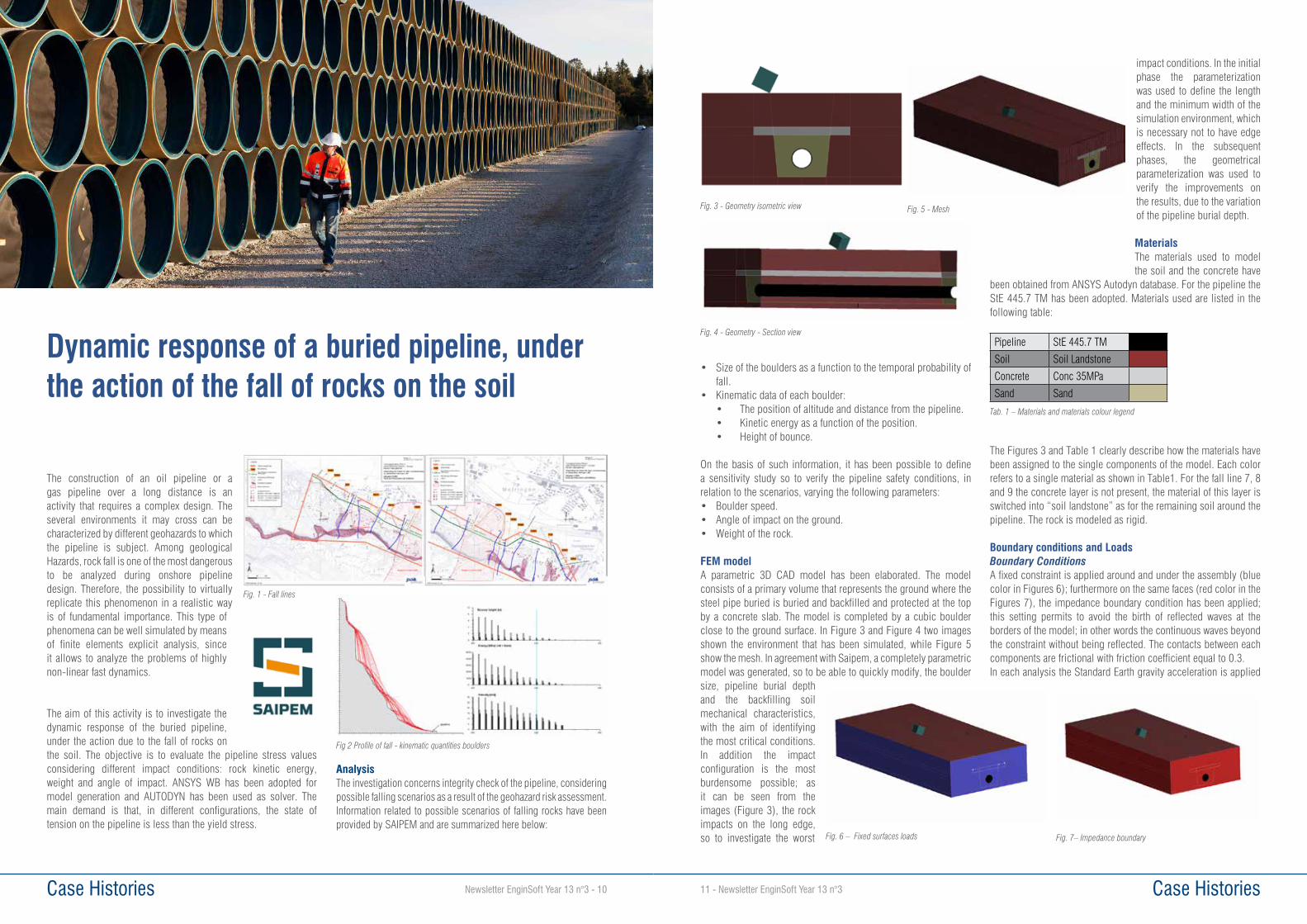
The construction of an oil pipeline or a gas pipeline over a long distance is an activity that requires a complex design. The several environments it may cross can be characterized by different geohazards to which the pipeline is subject. Among geological Hazards, rock fall is one of the most dangerous to be analyzed during onshore pipeline design. Therefore, the possibility to virtually replicate this phenomenon in a realistic way is of fundamental importance. This type of phenomena can be well simulated by means of finite elements explicit analysis, since it allows to analyze the problems of highly non-linear fast dynamics.
The aim of this activity is to investigate the dynamic response of the buried pipeline, under the action due to the fall of rocks on the soil. The objective is to evaluate the pipeline stress values considering different impact conditions: rock kinetic energy, weight and angle of impact. ANSYS WB has been adopted for model generation and AUTODYN has been used as solver. The main demand is that, in different configurations, the state of tension on the pipeline is less than the yield stress.
AnalysisThe investigation concerns integrity check of the pipeline, considering possible falling scenarios as a result of the geohazard risk assessment. Information related to possible scenarios of falling rocks have been provided by SAIPEM and are summarized here below:
Dynamic response of a buried pipeline, under the action of the fall of rocks on the soil
Fig. 1 - Fall lines
Fig 2 Profile of fall - kinematic quantities boulders
Case Histories11 - Newsletter EnginSoft Year 13 n°3
• Size of the boulders as a function to the temporal probability of fall.
• Kinematic data of each boulder: • The position of altitude and distance from the pipeline. • Kinetic energy as a function of the position. • Height of bounce.
On the basis of such information, it has been possible to define a sensitivity study so to verify the pipeline safety conditions, in relation to the scenarios, varying the following parameters:• Boulder speed.• Angle of impact on the ground.• Weight of the rock.
FEM modelA parametric 3D CAD model has been elaborated. The model consists of a primary volume that represents the ground where the steel pipe buried is buried and backfilled and protected at the top by a concrete slab. The model is completed by a cubic boulder close to the ground surface. In Figure 3 and Figure 4 two images shown the environment that has been simulated, while Figure 5 show the mesh. In agreement with Saipem, a completely parametric model was generated, so to be able to quickly modify, the boulder size, pipeline burial depth and the backfilling soil mechanical characteristics, with the aim of identifying the most critical conditions. In addition the impact configuration is the most burdensome possible; as it can be seen from the images (Figure 3), the rock impacts on the long edge, so to investigate the worst
impact conditions. In the initial phase the parameterization was used to define the length and the minimum width of the simulation environment, which is necessary not to have edge effects. In the subsequent phases, the geometrical parameterization was used to verify the improvements on the results, due to the variation of the pipeline burial depth.
MaterialsThe materials used to model the soil and the concrete have
been obtained from ANSYS Autodyn database. For the pipeline the StE 445.7 TM has been adopted. Materials used are listed in the following table:
The Figures 3 and Table 1 clearly describe how the materials have been assigned to the single components of the model. Each color refers to a single material as shown in Table1. For the fall line 7, 8 and 9 the concrete layer is not present, the material of this layer is switched into “soil landstone” as for the remaining soil around the pipeline. The rock is modeled as rigid.
Boundary conditions and LoadsBoundary ConditionsA fixed constraint is applied around and under the assembly (blue color in Figures 6); furthermore on the same faces (red color in the Figures 7), the impedance boundary condition has been applied; this setting permits to avoid the birth of reflected waves at the borders of the model; in other words the continuous waves beyond the constraint without being reflected. The contacts between each components are frictional with friction coefficient equal to 0.3.In each analysis the Standard Earth gravity acceleration is applied
Pipeline StE 445.7 TM
Soil Soil Landstone
Concrete Conc 35MPa
Sand Sand
Tab. 1 – Materials and materials colour legend
Fig. 3 - Geometry isometric view
Fig. 4 - Geometry - Section view
Fig. 5 - Mesh
Fig. 6 – Fixed surfaces loads Fig. 7– Impedance boundary

13 - Newsletter EnginSoft Year 13 n°3 Case HistoriesCase Histories Newsletter EnginSoft Year 13 n°3 - 12
and the rock has an initial velocity derived from the energy provided by the geohazard risk assesment report and a specific impact angle (Figures 8).
Results 27 simulations were carried out; for each fall line, the total deformation of the entire assembly and the equivalent Von Mises Stress on the pipeline at the time, at which the worst condition occurs, are shown. In the following images are showed the basic output values that have been calculated.
ConclusionsIn this study the behaviour of a buried pipeline under the action of indirect loads due to falling rocks was analyzed, by means of simulations with the explicit code AUTODYN. The impact conditions were taken from the geohazard risk assessment report provided by SAIPEM.The results have shown the behaviour of the soil-pipeline system in different configurations and the related values of stress of the pipe. Such information allowed Saipem to investigate how pipeline burial depth influences the structural behaviour of the pipe subject to ground surface rock fall impacts.Table 2 summarizes the results for each line of drop, considering
the worst impact configuration, therefore more conservative one.Downstream of these simulations, it could be taken into account the creation of response surface, using modeFRONTIER, as a function of the parameters of the rock (speed, size, angle of impact) and the soil (thickness above the pipeline), in order to assess in a fast and efficient way to other possible critical configurations.
For more information:Massimo Tomasi. [email protected]
Fall line Mass weight (kg)
Rock Kinetic Energy (MJ)
Safety condition
Thickness of soil to add
(m)
Safety condition
after added soil
1 4600 9.1 SAFE /
2 2300000 5000 CLOSE TO LIMT
0.75 SAFE
3 1150000 3000 CLOSE TO LIMT
1.2 SAFE
3 9000 23 SAFE /
4 1150000 2000 SAFE /
6 115000 150 SAFE /
7 1840000 2500 CLOSE TO LIMT
3.2 SAFE
7 6900 10 SAFE /
8 115000 1800 CLOSE TO LIMT
1.3 SAFE
9 46000 8 SAFE /
Tab. 2 - Kinematic configuration, safety conditions, Added thikness soil in order to improve the safety, safety conditions after Added soil thikness
Fig. 8 - initial velocity applied to the rock
Fig. 9 - Total Deformation environment section 1
Fig. 10 - Total Deformation environment section 2
Fig. 11 - Equivalent Von Mises stress on the pipeline
Uteco Converting S.p.A. is the world leader in the production of printing machines designed for the most diverse flexible packaging applications.Uteco offers innovative solutions through its broad range of flexographic and rotogravure printing machines, laminating machines and high-tech machines with special configurations, while constantly focusing on research and innovation.
IntroductionHigh production rate and printing quality are not alternative choices when talking about Uteco printing machines. These are pre-requisites that are met by the adoption of the most advanced technologies in the fields of research, design, production and services. Among these technologies Uteco has decided to apply Computational Fluid Dynamics to support the design of its printing machines. In particular CFD simulation has been applied to study and improve the printing and the ink drying processes.
High Quality Printing at High RateWhen printing at high speed with Rotogravure Presses (Figure 1) the printing quality might be affected by air entrainment, that is mainly due to two distinct phenomena. The first type of air entrainment is due to air drag associated to the high rotational speed of the roller. The second type of air entrainment is due to ink splashing produced by the drag of the roller onto the ink (Figure 2).
High Quality Printing with CFD
Figure 1 – 3D CFD model of the Rotogravure Press Figure 2 – 2D slice showing in red the ink distribution and the ink spalshing due to the roller drag and the effect of the doctor blade

Case Histories15 - Newsletter EnginSoft Year 13 n°3 Case Histories Newsletter EnginSoft Year 13 n°3 - 14
from escaping into the external environment, where operators are located and might smell chemical solvents.The drying process is done through air boxes with multiple nozzles that impinge hot air on the moving film (Figure 4 and Figure 5).The design of ink drying systems has been heavily supported by CFD with multiple objectives, like evenly distribute the air flow at the nozzles, assure the total ink evaporation, reduce the pressure losses in the air boxes, evaluate the minimum suction or flow rate to prevent solvent escape.In few words the aim is to evaporate the ink with the minimum energy and in a safe way.
The first and most important design objective is to make sure that each nozzle is fed with the same amount of air and that the velocity along the linear nozzle is uniform (Figure 5). If this target is reached, then the evaporation rate will be uniform on the moving film.But this is not enough, the total volatile matter evaporation must be guaranteed before the exit of the film from the drying area. For this reason the CFD models, in addition to predicting the velocity distribution, must be able to explicitly simulate evaporation and the transport and diffusion of vapor.
Specific models have been implemented to predict the evaporation rate both for water and chemical solvents. The same models allow also to estimate for each type of solvent the minimum operating temperature to guarantee total evaporation (Figure 7). This kind of information is of paramount importance both for the printing quality and to minimize energy consumption, that are two of the reasons why customers purchase Uteco printing machines.After the evaporation, vapor suction must be guaranteed for safe operation. This is done by reducing the area where solvent vapor can escape to the external environment and by creating a proper suction effect. Also in this case CFD modelling allows to predict vapor escape and to calculate the minimum suction level that assures total vapor capture with the minimum energy consumption.
ConclusionsIn the search for quality and innovation Uteco Converting makes extensive use of Computational Fluid Dynamics, mainly to guarantee and improve printing quality, with minimum energy consumption and in safe conditions for the operators.CFD has been applied to the simulation of Rotogravure Presses to prevent printing defects and improve the fluid-dynamic behavior of the presses. It has also been applied to the ink drying process, where the high production rate, the energy consumption and safety aspects make the solvent evaporation a real challenge.
For more information:Massimo Galbiati, [email protected]
Figure 5 – Air velocity vectors, showing uniform air flow impinging on the moving film
Figure 6 – Vapor concentratuion in the evaporation and suction areas
Figure 7 – Ink evaporation from the moving film versus operating temperature
Both the two phenomena increase their negative effect on the printing quality as the production rate increases, and both of them can be managed by adopting appropriate design solutions.Regarding the air dragged by the rotating roller at the interface with ink, Uteco developed solutions based on specific devices, that are located below the roller and that reduce the amount of entrained air.In this case CFD simulation was used to understand the phenomenon and to design the geometry that reduce to a minimum the risk of having printing defects.The ink splashing is instead something that was initially less clear and intuitive. What was clear is that that the printing defects were due to air bubbles inside the ink volume, but the question was: “Where do the bubbles come from?”.What is actually visible looking at the printing machine is just foam at the ink free surface. Uteco and also customers perceive foam as something to be avoided and associate foam to potential printing defects.
In reality foam is only a symptom of the real source of printing defects, that is ink splashing.Ink splashing takes place in the rear, hidden area of the machine, where ink is lifted up by the roller and then suddenly put to a halt by the “doctor blade”. The consequence is that ink tends to fall and splash at high velocity, thus mixing with air and generating foam. Foam is generated in this hidden part of the machine and then moves together with the main ink stream and it is made visible in the front part of the machine.So foam is produced by ink splashing, but it is not the cause of printing defects. As a matter of fact ink splashing produces also air entrainment and air bubbles growth inside the ink volume just beneath the roller. This is what must be avoided or limited.The CFD modeling of the Rotogravure printing process allowed to understand these kinds of phenomena and once the source of the problem was known, finding the solution was quite easy.A new system was implemented to minimize ink splashing and mixing between air and ink. Air bubbles in the ink volume are prevented from reaching the printing area and at the same time foam generation is limited.
The CFD simulations of the Rotogravure Press were developed both using 2D and 3D models. The 2D model was helpful to understand the physical phenomena associated to the ink-air interaction and to verify the efficacy of the new system in terms of air entrainment reduction. The same 2D models allowed also to understand that it is fundamental to dispose the air bubbles by facilitating air movement from the area close to the roller to less risky areas away from roller. The 3D CFD models allowed to calculate and visualize the extension of the air bubbles underneath the roller in different geometrical configurations. It is quite evident from the results that the new system reduces the dimension of the air bubbles and creates a pressurization of the ink volume, that helps to decrease air entrainment also at the sides of the roller, where most of the printing defects are located.
The 3D model clearly demonstrated also the improvements in terms of ink flow distribution towards the ink recirculation system, that is located in the visible area of the machine (Figure 3). This aspect, together with the limited foam formation, can be regarded also as an “aesthetic improvement” of the machine fluid-dynamic behavior and is perceived as a proof of high quality printing from the customer’s perspective.
Efficient Ink DryingAfter the printing phase, the volatile part of ink has to be evaporated. The volatile part might be water or chemical solvents. The first challenge about ink drying is to fully evaporate the volatile part on a fast moving film. The second one is to prevent the vapor
Figure 3 – comparison of ink streamlines without (upper picture) and with (lower picture) the new system to reduce printing defects
Figure 4 – Large air box with multiple nozzles

Newsletter EnginSoft Year 13 n°3 - 16 Case Histories
Design of pressure pipelines for hydropower plants has become more and more critical due to the high safety level requested, the severe and complex operating scenarios and the need to balance reliability of the equipment and cost saving. From this point of view, the application of numerical simulations during the design workflow can be beneficial. With FE analyses, in fact, complex working conditions can be explored in order to check the robustness of achieved design and avoid insurgence of failures which can lead to onerous extraordinary maintenance activities. Respect to the typical design “by formula”, the use of sophisticated numerical analyses is a powerful approach for cost reduction by design optimization. Thickness optimization of duct plates or reduction of the welds passes, for instance, can be considered after a FE analyses if results point out that enough safety factor is present in current design. In this article, a survey of recent works done for Massingir dam, El Quimbo
and Cerro de Aguila Hydroelectric Power projects has been reported and possible development for the application of CAE methodologies for hydropower industrial field have been also discussed. These works have been carried out in collaboration with ATB Riva Calzoni.
IntroductionThis article summarizes the numerical simulation activities carried out together with ATB Riva Calzoni on Massingir Mozanbique, Cerro de Aguila in Peru and El Quimbo Colombian hydropower plants.Rehabilitation works of Massingir plant in Mozambique comprise the installation of 6.4 meter diameter steel liners into the existing reinforced concrete outlet conduits, installation of hydro-power offtakes, mass and heavily reinforced infill concreting and grouting, and rehabilitation of the two downstream radial control gates, including entirely new hydraulic and electrical equipment. Cerro del Aquila hydroelectric Project, is located in Peru, represents the third step of exploitation of Mantaro River for energy production. The project considers a total installed capacity of 510MW over a gross head of about 250 m. A concrete gravity dam 84 m height is foreseen. Dam is equipped with a spillway (4 radial gates 12x14m) and a bottom outlet completely integrated in the dam body (8 conduit 4.5x6.2m each) for flushing purpose. The waterway complex system considers: headrace tunnel 5.6 km length 10.8 m diameter, pressure shaft 236 m height 8 m diameter, surge shaft 92 m height 14 m diameter and tailrace tunnel of 1.8 km. The underground power house is equipped with 3 Francis turbines 170 MW each for a total installed capacity of 510 MW. For the El Quimbo power station 150 m high dam will be built for a total power capacity of 400 MW and an average energy production of
On the application of numerical analyses to hydropower plant design
Fig. 1 – Equivalent stress map of Cerro de Aguila Y-pipe with detail of secondary stress areas
Case Histories17 - Newsletter EnginSoft Year 13 n°3
2,200 GWh/year generated by means of two vertical turbines.For all these projects, Y-shaped, Tee bifurcations and reinforced ducts have been analyzed. By means of numerical simulations, in fact, resistance of nonstandard components can be easily assessed. Shape optimization and thickness reduction can be also performed by analyzing complex conditions where “by formula” approach cannot be applicable. Aim of the analyses is to check the structural integrity of the equipment which have been preliminary designed and review the structural details at critical area. With a cost saving purpose, further action have also been suggested. With FE analysis the thickness of plates used can be optimized and also welding operations, which is one of the most expensive aspects of fabrication, can be significantly reduced.
Numerical AnalysesIn this article several analyses are presented to show the applicability of numerical simulations in the design workflow for typical structural integrity check and sophisticated assessment of mechanical resistance, such as instability due to buckling phenomena or steel vs. concrete interaction to prevent damage of duct containment structures. Y-shaped pipe connection (i.d. 4800 mm) of Cerro de Aguila plant has been investigated for structural resistance by considering standard operating conditions and hydraulic test. Detailed geometry with external reinforcing rings has been modeled using shell elements. For standard operating conditions a pressure of 3.5 MPa has been assumed considering maximum range of operating temperatures (20 ± 10 °C). As the end sections of the Y-connection pipes are fully constrained by concrete support structure, even moderate temperature variation of 10° C could significantly influence the stress status. For the structural assessment, static structural analyses have been carried out. Geometry non linearity (large deflection) has been also taken into account. Acceptance stress criteria in compliance with UNI EN 10028-3:2004 standard have been assumed by applying safety factors of 1.8 and 1.25 for primary and secondary stresses respectively at operating conditions. For hydrostatic shell test same factor have been reduced to 1.3 and 1. Results pointed out that structural resistance is guaranteed at the analyzed condition and a general thickness reduction can be considered as stress status is globally lower than the allowable limits. Areas of secondary stresses where further reinforcing can be introduced have been also highlighted in Fig.1.
Another nonstandard part of hydropower plant where the application of numerical simulations is beneficial to improve the design and optimize the use of materials and the fabrication procedures is related to reinforced ducts. By means of reinforced pipeline, transition between circular and rectangular sections of the liner could be efficiently designed by containing the overall dimensions of the pipes and external reinforcing rings. These kind of pipes, when subjected to internal pressure and temperature variation, have a complex stress strain status in particular at transition between round and square section. FE analyses are helpful to properly calculate the secondary stress level and consequently select the suitable thickness of duct plate and reinforcing ring. The reinforced pipeline section of El Quimbo hydropower plant in correspondence of gate guidance and support section has been analysed under the action of pressure and thermal loads. Aim of the analyses was a
structural assessment according to ASME code and the selection of reinforcing plates at the most critical areas. 3D FE models of liner different portion have been developed by using shell elements. Reinforcing rings and their connections with main pipe have been modelled with detail. Static structural analyses have been carried out by considering both the “as built” geometry and a 3 mm of internal corrosion on the wet surfaces according to maximum corrosion allowance. Stress maps
shown in Fig.2 pointed out a secondary stress concentration at the square section pipe and in correspondence of first reinforcing rings. The performed simulations allowed a proper selection of reinforcing ring plates thickness to avoid excessive stress intensification at square pipe corner an subsequently non tolerable distortions.For tee type bifurcation of Massingir dam, structural analyses of pipeline involved the interaction between steel pipe and concrete tunnel. Damage of the concrete support structure in fact is one of the failure phenomena which has to be avoided because a cracked masonry could not properly support the pipeline leading to local collapse of the structure. Expensive and time consuming maintenance and repair operations must also be carried out in case of damage of concrete channel. In order to perform the assessment respect to such damage mechanism, 3D nonlinear analyses have been carried out by modelling the interaction between tee bifurcation and channel internal surface. Maximum gap between steel plates and channel due to concrete retirement after casting has been also taken into account as it significantly affects the contact pressure distribution between steel plate and channel and the concrete stress level accordingly. Longitudinal and vertical ducts with reinforcing ring have been modelled with shell elements while for the portion of support structure solid
Fig. 2 – Stress distribution on reinforced pipe sections for El Quimbo hydropower plant
Fig. 3 – Stress distribution on bifurcation of Massingir plant
Fig. 4 – Contact pressure distribution between concrete channel and steel bifurcation for Massingir plant

Case Histories19 - Newsletter EnginSoft Year 13 n°3 Case Histories Newsletter EnginSoft Year 13 n°3 - 18
elements have been used. Both internal hydraulic pressure with an hydrostatic distribution and thermal gradient of 40° C, representing maximum temperature range which the pipe could be subjected to, have been considered in the calculations. Stress status on the steel parts have been checked assuming ASME VIII criteria while, for limit contact pressure on concrete structure, internal specification from ATB Riva Calzoni based on the concrete casting quality have been considered. The stress maps on the bifurcation steel plate are shown in Fig.3. Stress is globally lower than allowable limit both on longitudinal and transversal pipe suggesting that possible plate thickness reduction could be considered. Although secondary stress at bifurcation intersection where collar reinforcing ring is installed has been pointed out, such stress concentration is not critical for the pipe global stability and it is tolerable take into account stress limits according to ASME code. Fig.4 show a detail of contact pressure between steel plates and concrete structure. Almost uniform contact pressure has been found at main pipe, as expected reduction of contact pressure (non-contact) occurred in correspondence of reinforcing rings which constraint the pipe radial deformation. Intensification of contact pressure has been highlighted at transition between transversal pipe and vertical bifurcation. Such pressure level , due to the sharp geometry at transition area, could lead to local concrete damage which do not globally compromise the structural resistance of the concrete channel. In order to avoid local peak compressive stress on the concrete a geometry smoothing of the transition area could also be considered.For the tee bifurcation further numerical investigation has been carried out to assess the weld resistance at operating and hydrotest condition and assess the protection against collapse for buckling. Numerical analyses allow to post process the stress results at weld seam and verify if selected weld thickness is adequate according to weld type - i.e. butt weld, filled weld, partial penetration etc. For this project EN 1993-1-8 technical standard has been applied and extraction of throat stress along weld principal directions has been considered for reinforcing ring fillet welds which are expected to be the most stressed ones. For protection against collapse from buckling a nonlinear analysis with large deflection has been carried out by considering a water pressure in the cavity between steel pipes and concrete channel. In separated-type water tunnel structure, when the point supported steel liner is subjected to the uniform external pressure, the contact between tunnel lining and liner is difficult to happen because the developed compressive hoop thrust in pipe only shortens the circumference of liner and then enlarges the gap between liner and host. External pressure could be due to local leakages at pipe intersection or damaged area of the same pipe. The main functionality of reinforcing ring is to stiffener the main pipes and increase the limit loads at which global and local buckling will occur. For simple cylindrical reinforced pipe analytical approach is available for buckling load calculation, while for complex geometries, such as the tee bifurcation under investigation, FE analyses are needed to properly calculate the critical pressure without underestimation of that phenomenon. Consequences of a collapse for buckling of a portion of the steel liner, in fact, could be extremely dangerous for the safety of people operating in the plant area. Time consuming and expensive replacement activities may be necessary to restore the plant functionality. For this reasons, aim of the numerical analyses is to estimate with reliability the critical external pressure which induces the collapse for buckling of the
bifurcation and check if suitable safety factor respect to maximum design external pressure is present. Nonlinear FE Analyses by considering elastic-plastic material has been carried out by progressively increasing the external pressure up to the analysis non convergence. Last converged step represents the critical pressure which has to be considered for the stability checks. Deformed shape of bifurcation at collapse is shown in Fig.5. It is clear that non symmetric deformation is induced by bifurcation geometry and main instability shape involved the longitudinal pipe near the intersection with vertical duct. 1.53 MPa has been calculated as critical pressure which is about 10 time the maximum external design pressure. Therefore, by considering typical acceptance criteria which assumes a minimum safety factor of 2, steel liner can be considered safe respect to buckling collapse. With same approach described previously, a weld check can be also performed for considering twice the external design pressure.
Conclusion and RemarksThe activities reported in this article pointed out that numerical FE analyses can be successfully introduced in the design workflow of hydropower plant equipment. Examples of analysis reported highlight that, by means of simulation, severe load conditions and complex geometries can be easily analysed to confirm robustness of design and identify the aspects where a design review or optimization could be introduced with cost saving purpose. As regards the applicability of numerical analyses to hydropower project, fluid structure interaction (FSI) can be considered as a next step to be implemented in the design workflow. Estimation of structural response to fluid induced vibrations for flow regulating parts such as gate and valve can be solved via numerical approach. Furthermore, the estimation of equipment fatigue remaining life in order to properly schedule maintenance operations and avoid problematic and expensive emergency repairs can be considered as a critical issue which will be more and more requested. From this point of view, sophisticated fitness for service numerical analyses will be a powerful tool to give fast and reliable response and to gain a competitive advantage over the competitors.
AKNOWLEDGEMENTSThe activities object of this article have been carried out in collaboration with ATB Riva Calzoni hydropower division. A special thanks for the support to eng. Floriana Maria Renna, eng. Paolo Sandonà, eng. Andrea Guerini and Diego Signorini.
For more information: Stefano Cavalleri, EnginSoft [email protected]
Fig. 5 – Deformed shape of bifurcation at buckling collapse for bifurcation of Massingir plant
Autec Safety Remote ControlAutec Safety Remote Control is an Italian company leader in the design and manufacturing of wireless radio remote controls for industrial/construction cranes and mobile machinery for off-highway applications.Autec improving processes are guided by 3S principle, i.e. excellence in Safety, Solutions and Service EnginSoft helps Autec on each ‘S’ using LS-DYNA.
Safety: LS-DYNA has been used to simulate drop tests and falling object tests to help engineers to choose the best solution to guarantee a good resistance of the Remote Control that can operate amid challenging circumstances on highly demanding environments Solutions: simulations, introduced in the early phase of the concept design, help Autec to choose the most efficient design and the best material for specific customer needs. A well correlated FEM avoid to build up many prototypes and to do many physical tests reducing R&D costs and time development product.Service: Autec believes that customers are the lifeblood of any business, so it is important to place an emphasis on the customer experience both before and after a sale is made. The simulations is one of the tools used to reach this objective and it helps Autec to create “Customers for Life” by the design of reliable products.
Remote Control Device: Brief DescriptionThe AIR series includes a wide range of transmitting units (handheld & joystick) and receivers that make it suitable for every remote control need in both industrial lifting and automation. Included among the features specific to the AIR Series are: Dual-band radio (433MHz, 915MHz), automatic frequency search, leds or graphic display for system feedback and the ability to be used in multiple-unit systems.
The object of the analysis is the model of radio remote control LK Neo. LK Neo is a push button transmitting unit, available in 6, 8, 10 and 12 keys. In addition there are 6 and 10-button configurations with a 1.8’’ customizable colour display.
The main standards for industrial environmental provide general requirements covering the construction, test and marking of electrical appliances.
Test DescriptionAccording to the Standard Regulation two main tests have been performed:• Drop Test• Falling Object Test
Virtual Drop Test and Falling Object Test on Safety Remote Control
Figure 1 - Radio remote control model LK NEO 12

Case Histories Newsletter EnginSoft Year 13 n°3 - 20
Drop Test Drop Test is the free fall of the remote control from 1 m height. This test is repeated for several positions of the object to avoid braking of the component during real drop.
Falling Object Test Falling Object Test is the drop of a standard 1 kg dart from 0.7 m of height on the remote control. Standard Regulation prescribes that the dart can impact everywhere on the component; simulations have been tested for the most critical areas: battery compartment with and without the battery, front cover, rear cover, side seal area.Standard Regulation prescribes that, after the described tests, the remote control must not show serious damages and it has to work correctly.
FE ModelingThe remote control CAD was meshed with 2D and 3D elements. The upper and lower covers, the battery cover and the gasket are modeled with tetra elements with average mesh size of 1.5mm to consider all the details of the CAD. The internal electronic components were modeled with 2D elements because they are considered only for lay out and weight. The external keys have very simple geometry, so they were meshed as hexa elements to reduce the number of element in the model.
Battery coverThe battery cover has required a more detailed meshing with hexa elements to emphasize the correct behavior during the falling object test simulation.
A patch of hexa elements with a finer mesh size in the center of the cover, was necessary to catch the failure of battery cover.
ContactsThe contact between covers and seal has required a dedicated work to reach realistic results. Using null_shell elements LS-DYNA wasn’t able to solve all the compenetrations.The best solution to avoid any compenetrations, was a double symmetric contact *CONTACT_NODES_TO_SURFACE. For internal components a generic *CONTACT_AUTOMATIC_SINGLE_SURFACE was enough to check eventually contacts with covers.
Control keys and battery fixationThe remote control keys and the battery pins have a spring inside. Their stiffness is simulated using *CONSTRAINED_JOINT_CYLINDRICAL elements.
CPU timeThe FEM has 225000 DOF and the CPU time for each run is less than 3 hours on 16 cores. A full simulation loop consist of 13 runs, that takes about 2 days on 16 cores.
MaterialsCover material is a glass fiber reinforced polyamide, simulated as *MAT_24, through true stress/true strain experimental curves each strain rate. To better simulate the failure behavior, the non-local theory has been chosen (material card *MAT_NONLOCAL): in non-local failure theories, the failure criterion depends on the state of the material within a radius of influence which surrounds the integration point.
Case Histories21 - Newsletter EnginSoft Year 13 n°3
An advantage of nonlocal failure is that mesh size sensitivity on failure is greatly reduced leading to results which converge to a unique solution as the mesh is refined. Without a nonlocal criterion, strains will tend to localize randomly with mesh refinement leading to results which can change significantly from mesh to mesh. The nonlocal failure treatment can be a great help in predicting the onset and the evolution of material failure.
Figure 7 shows the difference between the standard and non-local theory. The failure is mesh independent, is more homogeneous and realistic. Using this card CPU time increases significantly, is better to use it in reduced areas.
ResultsDrop TestThe FE analysis was performed for 7 different tests: drop on each side and drop on a single edge. All tests shows no critical areas on the remote control structure. The following results refers to the drop of the remote control on the single edge.
Below some details of effective plastic strain contour. The plastic strain values achieved are lower than critical values, therefore the integrity and functionality of the remote control is guaranteed.
Falling Object testThis test was performed on the most critical areas of the remote control, close to the junction of the two covers and on the top and on the bottom faces of the cover. In each case some cracks are occurred.
These results have been correlated with the physical tests. In following pictures, the comparison between laboratory tests and corresponding FE analysis results is shown.
Result analysis and improvementsDuring drop and falling object tests the remote control must not show any cracks. Both physical tests and simulations has confirmed that the original remote control was not able to fulfil the requirements. As suggested by AUTEC, EnginSoft did some analysis using polyamide reinforced with different percentage of glass fiber. Most critical tests has been repeated with these materials and after a few simulations, a new material has been identified to avoid any cracks during tests. Fig. 12 show a comparison between original and new material in term of effective plastic strain.
Figure 6 - Glass fiber reinforced polyamide true stress / true strain curve
Figure 7 - Difference between the standard and non-local theory
Figure 8 - Drop Test on an edge
Figure 9 - Effective Plastic Strain Drop Test
Figure 10 - Falling Object Test
Figure 2 - Drop Test and Falling Object Test
Figure 3 - FE model
Figure 4 - Battery cover detail
Figure 5 - Spring detail
Figure 11 - Correlation

23 - Newsletter EnginSoft Year 13 n°3 Case HistoriesCase Histories
The contours show the plastic strain values achieved are lower than critical values, therefore the integrity and functionality of the remote control is guaranteed using the updated material.
ConclusionTypically, the resistance of consumer goods is examined due to an impact after a free fall out of heights that represent their respective usage and many of the product checks include the testing of impact loading. Also the package industry shows large interest to assure a high impact reliability during transport of their components. EnginSoft has a team of expert engineers coming from industry, dedicated to explicit dynamic simulation with LS-DYNA, who can help industries to design optimized components and packaging.LS-DYNA is a very useful tool to simulate drop tests and falling object tests. Very good correlation between numerical analysis and experimental tests in term of component failure has been confirmed. Once more it has been proved that a correct modeling of all the components and the right choice of the material law is very important.A synergy between LS-DYNA and modeFRONTIER can further improve components , predict low velocity impact damage on components and avoid damage in components during their respective usage or transportation. Due to the fact that many simulations are needed to test the remote control behavior according with the actual regulations, it has been very important to define a model that runs in a few hours. A good compromise between CPU time and results has been reached; all the tests to validate the component run in less than two days of simulation. This goal is useful if many solutions have to be tested and compared to find the best one in term of performances, weight, materials, costs. Again simulation can help engineers to choose the best solution reducing R&D timing. In this specific case different materials has been tested and a new one has been identified for the remote control to avoid any cracks during the tests as required by the regulation. Using simulation in the early phase of the concept design has many advantages. Component optimization in term of design and material can reduce weight and costs production. An efficient integration between AUTEC R&D department and EnginSoft simulations engineering team has an important added value for future remote control design reducing the number of physical tests and decreasing the time to market.
Giuseppe Battistella, AutecValerio Caputo, Danilo Col, EnginSoft
For more information:Danilo Col, EnginSoft - [email protected]
17th - 18th
OCTOBER2016
PARMAPAGANINI CONGRESSI
ITALY
FOR MORE INFORMATION
The purpose of the contest is twofold: offering recognition to excellence and innovation of projects developed in the
academic �eld and providing a privileged meeting space between the university experiences and the industrial world.
This contest is open to students, graduates, researchers, and / or faculty members such
as professors from Universities and Research Centers.
Sponsored by
Thin-wall structural parts produced by high pressure die casting (HPDC) are designed and applied in the automotive production sector. The Audi strategy is the application of lightweight alloy components produced by HPDC in the structure of future car bodies. One of the key components of this strategy is the shock tower. The research of smart control strategies in order to improve the quality and production efficiency of these parts is a main objective of the technical center for HPDC of AUDI AG. An optimized cognitive method is therefore introduced and integrated in a single centralized control system. The shock tower use case is the selected demonstrator for testing and validating the cognitive control system. Based on an intelligent sensor network, communication with all devices, process data management and a quality prediction in terms of filling and solidification defects, a vast improvement of the casting production process is expected.
IntroductionEU regulations for achieving long-term climate goals involve the development of cost effective CO2-reducing technologies, both for use in cars and for the production of cars. A weight reduction leads to a performance improvement and a lower fuel consumption, which makes a substantial contribution to achieving the objectives and future challenges of the automotive industry.
The technology in automotive lightweight construction has developed to a highly integrated overall concept with innovative materials and intelligent design principles and production processes that conserve resources. Innovative lightweight concepts such as space frame technology can only be applied using high pressure die casting (HPDC) parts for structural purposes in the car bodywork. The production of these large-
scale and thin-wall high tech parts requires high levels of investment on manufacturing means in order to provide stable and controllable process conditions. Process-accompanying quality measurements ensure that information is fed back to the central production process and that inaccurate machine settings and unnecessary rejects are avoided. Reliable information about the quality of a part immediately after the production process can help the worker to implement measures in a timely manner to readjust the parameters of the production process.
Innovative control and real-time quality prediction for the casting production of aluminum alloy structural components
Fig.1 - Sensors in the cavity of the die and simulation to define the sensor locations
Figure 12 - Comparison between original and new material

Sezione25 - Newsletter EnginSoft Year 13 n°3 Case Histories Newsletter EnginSoft Year 13 n°3 - 24
Requirements of Structural PartsStructural parts produced by HPDC play a significant role in the future Audi lightweight strategy. The shock tower is a thin walled aluminum cast component for the vehicle structure. It is classified in the category of crash relevant parts, which require good mechanical behavior with respect to strength and ductility. It is made off AlSi10MnMg (EN AC-43500) die-cast alloy employing the vacuum die-casting method. To ensure a certain value for the strength and ductility related properties, solution-annealing and artificial aging has to be performed by way of T6 heat treatment. The shock tower is the chosen demonstrator for the research and validation of the smart control strategy for the die casting production in the Technical Center for HPDC at AUDI AG in Ingolstadt. The research activities are part of the project referred to as “MUSIC” (MUlti-layer control & cognitive System to drive metal and plastic production line for Injected Components) in the Seventh Framework Program of the European Union. The new approach in the field of information and communication technologies (ICT) will be explained in this article with respect to the following topics:
• Intelligent sensor network for measuring the effect of the process setup and the stability of the thermo-mechanical behavior of the die.
• Connection with all devices for acquiring data in a centralized database.
• Configuration of the cognitive model for predicting the quality indexes relative to input in real-time.
• Smart control application in production.
Intelligent Sensor NetworkA mandatory requirement for the smart control strategy is the acquisition and storage of all data which influences the quality of the part, such as process parameters and sensor signals. In a first step, the existing die has to be modified to obtain an enhanced sensor network which is sensitive to casting defects. Process variables, which can be measured inside the cavity of the die by a sensor, are typically the temperature, the pressure and the time to melt contact. The sensors are positioned in the die based on simulation results. Possible positions for the integration of sensors in an HPDC die are limited to geometrical characteristics of the cast part and the resulting cavity of the die and interfering contours such as ejectors and cooling channels. It could thus happen that sensors cannot be placed in areas where quality defects will mainly appear. The challenge is to create a sensor network which can indicate all relevant quality defects
within the existing restrictions of an existing die. The positions of the sensors within the cavity of the die are shown in Figure 1.Further information can be provided by sensors which are not positioned directly in the cavity of the die. Special stroke sensors were installed in order to monitor the movement of the squeezers. An opening of the die during the casting process was detected by four mold separation sensors which are placed in each corner of the die. In particular, the temperature control of the die has a great influence on the quality of the part and therefore it is monitored by a thermal-imaging camera system. The efficiency of the spraying process and the settings of the external thermoregulation devices can easily be monitored by using infrared imagery to measure the temperature in the areas of special interest on the fixed and moveable plates of the die before and after the spraying process.
Connection with all devicesThe main focus is on the sensor network in the die and the parameters of the shot curve, since these have the greatest influence on the quality of the part. In addition, the data concerning the connected peripheral devices has to be collected. For this reason the new OPC UA standard has been used to ensure a uniform approach in communication with the devices inside the HPDC cell. The connections with all devices can be seen in Figure 2.The network with OPC UA communication includes the 2000t high pressure die casting machine, the thermoregulation, the sensor network and the thermal-imaging camera system.
Configuration of the cognitive modelFor training the cognitive model, several quality characteristics have to be checked at different stages along the process chain. Starting with the melting process where the chemical composition analysis and the density index (i.e. gas content) of the liquid melt has to be checked. The cast part is analyzed by X-ray according to the specifications of ASTM E505 to detect shrinkage and porosity. Deformation of the part is measured by a device with digital gauges and stored in the database with respect to distortion before and
Fig. 2 - Process chain with data connection
after heat treatment. After heat treatment, the number and size of blisters on the surface of the entire part were documented. Finally, the tensile tests for the mechanical properties were performed for different areas of the part separated according to the distance from the ingate. The results of all quality checks were used to build a real meta-model of the process. Furthermore, data from the simulation was used to build a first virtual meta-model and to compare it and improve it with data from the real meta-model. For both meta-models a design of experiments was developed to configure different process parameters and sensitivity to sensor data and quality criteria . For the meta-model and the real casting process, thresholds to the permissible quality level of each quality defect have to be determined. It is possible to define a minimum level of quality for each area of interest based on the original specifications associated with an area of interest and a type of defect. Visualization of the meta-model is based on the correlation matrix and the parallel chart where the thresholds can show the effect on the process parameters to be used, or vice versa.Since an HPDC die is a large investment, the die life influenced by different damage mechanisms and process parameters was also taken into account. The die life model will be implemented in the meta-model to prevent parameter settings which will lead to an excessive damage of the die in an early stage.Traceability of parts is mandatory for assigning the measured levels of the quality characteristics to the produced part. For this reason, a data matrix code is attached to each part. For those parts, which were not used for heat treatment, the insertion of an RFID capsule during the casting process was tested.
Smart control application in productionThe incremental learning family introduces a new way to optimize the accuracy of the quality forecast by searching for and selecting the best data mining algorithm among those available. Machine learning (ML) algorithms identify patterns in data and construct mathematical models using these patterns to achieve the best performance for the prediction and recalibration phases. The models need to be recalibrated in scenarios where new data become available, for example when a new quality inspection is performed during production, or when a new simulation process is completed. To maximize the accuracy of the predictions, it is crucial to develop an algorithm that is able to test the various available meta-models using the metric of cross-validation and to obtain the best one according to the imported data. New quality data is introduced using the 3D viewer web application in order to store them in the new extended table, selecting the location by clicking in the visualized geometry and applying the defect category and class from the available menu. The addition of new real-time observations allows the entire cognitive system to be quickly updated without the need to suspend production, thus without impacting the efficiency of the process. If some quality thresholds are set, the system responds during production by comparing the value of each prediction with the corresponding acceptability value for real-time predictions for rejects and good castings.
The “Smart Prod ACTIVE” tool (commercial name of the control & cognitive system) shows real-time quality results on PC, tablet or smartphone with information about the correlated causes generating the defects, about process stability and efficiency, and a statistic elaboration of the percentage of rejects and reference cost.
ConclusionsSince a reduction in the rejects rate will help to save money and energy during the production of castings, the use of a control and cognitive system will generate a benefit for the foundries. The preconditions for this are open interfaces and communication standards such as OPC UA. Especially with the increasing complexity of castings, a system with a reliable quality prediction and a well-founded database can help the worker to define and implement the right decisions.
AcknowledgmentsThis work was developed within the “MUSIC” Project (MUlti-layers control & cognitive System to drive metal and plastic production line for Injected Components), supported by European Union [FP7-2012-NMP-ICT-FoF] under grant agreement number n°314145. The authors would like to thank the MUSIC consortium (www.music.eucoord.com).
B. Kujat – AUDI AGN. Gramegna – EnginSoft SpA
M. Benvenuti – DTG
Presented at HTDC Conference 2016, Venice 22-23 June 2016, organized by AIM and published in the “La Metallurgia Italiana”,
issue nr. 6, June 2016
Smart Control and Cognitive System applied to the HPDC Foundry 4.0
A robust and competitive methodology developed under EU-FP7 MUSIC Project
Written at the end of the Project, this book, referred to High Pressure Die Casting (HPDC) of Aluminium alloys, intends to analytically describe methods,
tools, parameters and innovative approaches developed to monitor and control the process and the quality product.The book collects the guidelines to design and implement the Intelligent Sensor Network (ISN) in HPDC production line as first outcome of MUSIC project. The monitoring network is able to provide useable, meaningful and quantitative data on product quality, as well as to define strategies (varying production process parameters, changes to the tooling, etc.) to move toward higher quality product with economic efficiency.This real time control system capability is then presented and applied to industrial case-histories, showing how to train a cognitive-based ICT platform for the industrial optimisation of High Pressure Die Casting production transforming the acquired knowledge and control methods into know-how. If you are interesting in having a look at the book, go to: https://music.eucoord.com/Documentation/body.pe

Newsletter EnginSoft Year 13 n°3 - 26 Case Histories
BOMAG MARINI LATIN AMERICA (BMLA) is the world market leader in Compaction Technology and manufactures equipment for the compaction of soil, asphalt and refuse, and sanitary landfill. They wanted to improve the efficiency of the two main components that make up their Titanium 140 Asphalt Plant: the counter flow drying drum and the Multi Paddle Pug Mill mixer. To accomplish this, they needed a way not only to analyze the behavior of the material inside the equipment, but to test out potential solutions in a quick and cost-effective manner.
Reproducing the particle behavior inside the equipment using Discrete Element Method (DEM) software was the solution BMLA chose, but they needed a DEM tool that could handle the unique characteristics of their asphalt material. Throughout each component of the equipment, the DEM tool needed to be able to process a high mass flow rate of many tiny, uniquely shaped particles. In the mixing portion specifically, the DEM tool also needed to accurately represent the real-life “stickiness” and physical combination of the particles after a petroleum-based binding material is injected.
BOMAG MARINI discovered that their simulation requirements could be solved with the unique capabilities found within Rocky DEM software. In the first half of the study, Rocky was used to evaluate the particulate behavior along the drying section of their equipment. Rocky’s non-spherical particle abilities were used to create an 8-corner polyhedral particle set for the simulations. This unique particle shape was more representative of
the real-life material than the spheres or sphere clumps typically found in other DEM tools. Then, Rocky’s GPU processing capabilities were used to simulate the high mass flow rate they needed with substantially reduced computational impact when compared with
CPU processing. The GPU capabilities found within Rocky were critical for enabling them to maintain a high particle count while still keeping the simulation times reasonable.
SIMULATION RESULTSThe simulation results Rocky provided made it possible to assess the particle behavior in various cross-sections of the equipment, making it easy to compare the results with field observations in a qualitative fashion. In the second half of the analysis, the focus was the mixing section of the equipment.
BOMAG uses DEM (Discrete Element Method) to analyze particulate behavior in their asphalt plant equipment
The simulations of particles in the asphalt plant mixer using ROCKY platform provided us with an increase of 60% in the mixture residence time, directly impacting the final product and guaranteeing quality for our customers.
Elton Antonello Engineering Manager at BOMAG MARINI
Figure 1 Eight-corner polyhedral particles were used in the simulations
Case Histories27 - Newsletter EnginSoft Year 13 n°3
In this section, a binding material is injected, which is composed of asphalt cement (AC) and fine particles and then mixing fins are used to combine the binding with the particulates. The goal of this second study was to assess the impact of new configurations of fins compared to the original one.
For this second study to succeed, the simulation needed to consider how the asphalt cement adhered to particles, as well as the influence of fines on the cohesion between the particles and the adhesion of the particles to the walls. This was achieved by using Rocky’s cohesion/ adhesion models to calibrate the particles so that the influence of both the asphalt cement cover and the fine particles were reproduced. Rocky was able to accurately reproduce the formation of particle clusters due to the cohesive behavior, as well as the adhesion of particles to the walls.
Using the original simulation results as a guide, BMLA proposed modifications to the fins, which were then simulated in Rocky and compared to the original. The results showed that the redesigned fins improved the residence time in the mixing zone, that is, the mean
time the particles spend in this zone. The table below shows these results in percentages, which are higher for Design 2:
Rocky DEM software, then, proved to be a useful tool for reproducing the particulate behavior inside the Titanium mixer, as well as for testing new geometric configurations and its impact on the residence time of particles in the system, a key parameter for the process.
CHALLENGE Getting to know the material behavior inside an Asphalt Plant is very useful, as well as testing different designs, since this knowledge can guide decisions on equipment modifications and help increase productivity. However, those analyses are not possible without a powerful simulation tool.
SOLUTION Discrete Element Method (DEM) analyses using Rocky DEM software allowed a better understanding of the behavior of the particulate material in this Asphalt Plant equipment. Rocky’s qualitative and quantitative post-processing tools led to a detailed evaluation of the particulate flux considering different designs of the equipment.
BENEFITSSimulations considering different designs for the fins in the mixing zone of the Multi Paddle Pug Mill mixer were carried out. The results enabled an evaluation of the residence time of the particles in the equipment, a key parameter for the process.
Rocky DEM is distributed by EnginSoft. For more information: Massimo Tomasi, EnginSoft - [email protected]
Figure 2 - Side view of the equipment
Figure 3 - Particle behavior in the first four planes of analysis shown on top (from left to right)
Figure 4 - View of the original mixing zone. Formation of clusters due to cohesive behavior of particles can be observed, as well as adhesion to the walls
Table - Increasing Residence time for original configuration (1) and two proposed modifications (2 and 3)left to right)
BOMAG MARINI LATIN AMERICA is a manufacturer of compaction equipment for soil, and refuse, sanitary landfill, and asphalt plants. This includes all paving solutions, the quality of which are guaranteed by the FAYAT GROUP.
Rocky DEM, Inc. is the developer of Rocky, a powerful, 3D Discrete Element Modeling (DEM) program that quickly and accurately simulates the granular flow behavior of different shaped and sized particles within a conveyor chute, mill, or other materials handling equipment.
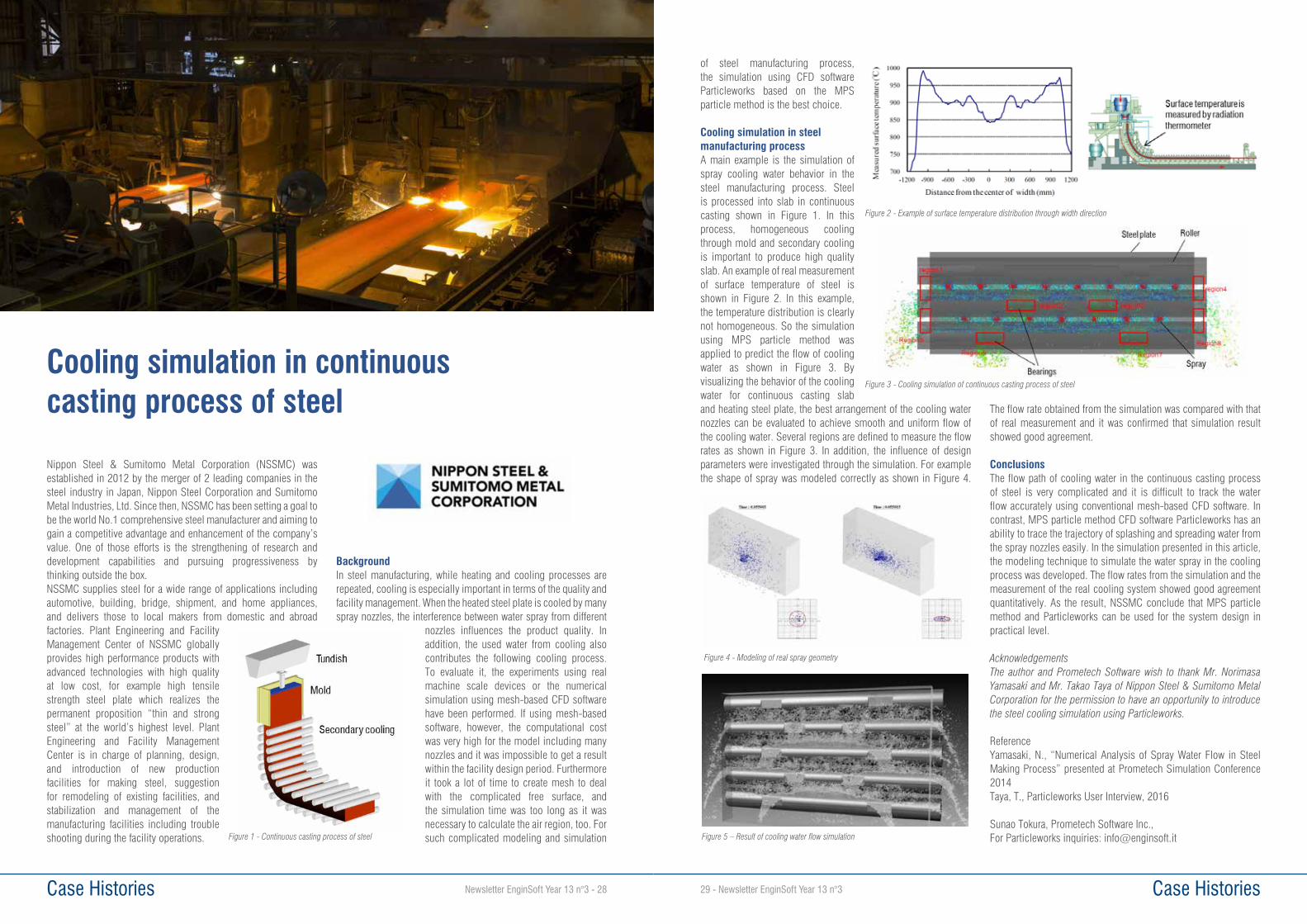
Newsletter EnginSoft Year 13 n°3 - 28 Case Histories
Nippon Steel & Sumitomo Metal Corporation (NSSMC) was established in 2012 by the merger of 2 leading companies in the steel industry in Japan, Nippon Steel Corporation and Sumitomo Metal Industries, Ltd. Since then, NSSMC has been setting a goal to be the world No.1 comprehensive steel manufacturer and aiming to gain a competitive advantage and enhancement of the company’s value. One of those efforts is the strengthening of research and development capabilities and pursuing progressiveness by thinking outside the box. NSSMC supplies steel for a wide range of applications including automotive, building, bridge, shipment, and home appliances, and delivers those to local makers from domestic and abroad factories. Plant Engineering and Facility Management Center of NSSMC globally provides high performance products with advanced technologies with high quality at low cost, for example high tensile strength steel plate which realizes the permanent proposition “thin and strong steel” at the world’s highest level. Plant Engineering and Facility Management Center is in charge of planning, design, and introduction of new production facilities for making steel, suggestion for remodeling of existing facilities, and stabilization and management of the manufacturing facilities including trouble shooting during the facility operations.
BackgroundIn steel manufacturing, while heating and cooling processes are repeated, cooling is especially important in terms of the quality and facility management. When the heated steel plate is cooled by many spray nozzles, the interference between water spray from different
nozzles influences the product quality. In addition, the used water from cooling also contributes the following cooling process. To evaluate it, the experiments using real machine scale devices or the numerical simulation using mesh-based CFD software have been performed. If using mesh-based software, however, the computational cost was very high for the model including many nozzles and it was impossible to get a result within the facility design period. Furthermore it took a lot of time to create mesh to deal with the complicated free surface, and the simulation time was too long as it was necessary to calculate the air region, too. For such complicated modeling and simulation
Cooling simulation in continuous casting process of steel
Figure 1 - Continuous casting process of steel
Case Histories29 - Newsletter EnginSoft Year 13 n°3
of steel manufacturing process, the simulation using CFD software Particleworks based on the MPS particle method is the best choice.
Cooling simulation in steel manufacturing processA main example is the simulation of spray cooling water behavior in the steel manufacturing process. Steel is processed into slab in continuous casting shown in Figure 1. In this process, homogeneous cooling through mold and secondary cooling is important to produce high quality slab. An example of real measurement of surface temperature of steel is shown in Figure 2. In this example, the temperature distribution is clearly not homogeneous. So the simulation using MPS particle method was applied to predict the flow of cooling water as shown in Figure 3. By visualizing the behavior of the cooling water for continuous casting slab and heating steel plate, the best arrangement of the cooling water nozzles can be evaluated to achieve smooth and uniform flow of the cooling water. Several regions are defined to measure the flow rates as shown in Figure 3. In addition, the influence of design parameters were investigated through the simulation. For example the shape of spray was modeled correctly as shown in Figure 4.
The flow rate obtained from the simulation was compared with that of real measurement and it was confirmed that simulation result showed good agreement.
ConclusionsThe flow path of cooling water in the continuous casting process of steel is very complicated and it is difficult to track the water flow accurately using conventional mesh-based CFD software. In contrast, MPS particle method CFD software Particleworks has an ability to trace the trajectory of splashing and spreading water from the spray nozzles easily. In the simulation presented in this article, the modeling technique to simulate the water spray in the cooling process was developed. The flow rates from the simulation and the measurement of the real cooling system showed good agreement quantitatively. As the result, NSSMC conclude that MPS particle method and Particleworks can be used for the system design in practical level.
AcknowledgementsThe author and Prometech Software wish to thank Mr. Norimasa Yamasaki and Mr. Takao Taya of Nippon Steel & Sumitomo Metal Corporation for the permission to have an opportunity to introduce the steel cooling simulation using Particleworks.
ReferenceYamasaki, N., “Numerical Analysis of Spray Water Flow in Steel Making Process” presented at Prometech Simulation Conference 2014Taya, T., Particleworks User Interview, 2016
Sunao Tokura, Prometech Software Inc., For Particleworks inquiries: [email protected]
Figure 2 - Example of surface temperature distribution through width direction
Figure 3 - Cooling simulation of continuous casting process of steel
Figure 5 – Result of cooling water flow simulation
Figure 4 - Modeling of real spray geometry
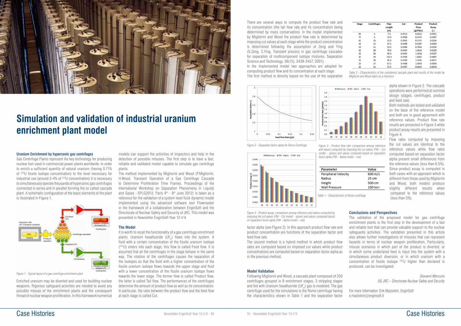
Newsletter EnginSoft Year 13 n°3 - 30 Case Histories31 - Newsletter EnginSoft Year 13 n°3 Case Histories
Uranium Enrichment by hypersonic gas centrifugesGas Centrifuge Plants represent the key technology for producing nuclear fuel used in commercial power plants worldwide. In order to enrich a sufficient quantity of natural uranium (having 0.71% of 235U fissile isotope concentration) to the level necessary for industrial use (around 3-4% of 235U concentration) it is necessary to simultaneously operate thousands of hypersonic gas centrifuges connected in series and in parallel forming the so called cascade plant. A schematic configuration of the basic elements of the plant is illustrated in Figure 1.
Enriched uranium may be diverted and used for building nuclear weapons. Rigorous safeguard activities are needed to avoid any possible misuse of the enrichment plants and the consequent thread of nuclear weapon proliferation. In this framework numerical
models can support the activities of inspectors and help in the detection of possible misuses. The first step is to have a fast, reliable and validated model capable to simulate gas centrifuge plants.The method implemented by Migliorini and Wood (P.Migliorini, H.Wood. Transient Operation of a Gas Centrifuge Cascade to Determine Proliferation Time Frames, Proceedings of the International Workshop on Separation Phenomena in Liquids and Gases –SPLG2012, Paris 4th – 8th June 2012) is taken as a reference for the validation of a system level fluid-dynamic model implemented using the advanced software tool Flowmaster in the framework of a collaboration between EnginSoft and the Directorate of Nuclear Safety and Security of JRC. This model was presented in Newsletter EnginSoft Year 12 n°4.
The ModelIt is worth to recall the functionality of a gas centrifuge enrichment plants. Uranium hexafluoride (UF6) flows into the system. A fluid with a certain concentration of the fissile uranium isotope (235U) enters into each stage, this flow is called Feed flow. It is assumed that all the centrifuges in the stage behave in the same way. The rotation of the centrifuges causes the separation of the isotopes so that the fluid with a higher concentration of the fissile uranium isotope flows towards the upper stage and fluid with a lower concentration of the fissile uranium isotope flows towards the lower stage. The former flow is called Product flow, the latter is called Tail flow. The performances of the centrifuges determine the amount of product flow as well as its concentration. In particular, the ratio between the product flow and the feed flow at each stage is called Cut.
Simulation and validation of industrial uranium enrichment plant model
Figure 1 - Typical layout of a gas centrifuge enrichment plant
There are several ways to compute the product flow rate and its concentration (the tail flow rate and its concentration being determined by mass conservation). In the model implemented by Migliorini and Wood the product flow rate is determined by imposing cut values at each stage while the product concentration is determined following the assumption of Zeng and Ying (S.Zeng, C.Ying. Transient process in gas centrifuge cascades for separation of multicomponent isotope mixtures, Separation Science and Technology, 36(15), 3439-3457, 2001).In the implemented model two approaches are adopted for computing product flow and its concentration at each stage.The first method is directly based on the use of the separation
factor alpha (see Figure 2). In this approach product flow rate and product concentration are functions of the separation factor and feed flow rate.The second method is a hybrid method in which product flow rates are computed based on imposed cut values while product concentrations are computed based on separation factor alpha as in the previous method.
Model ValidationFollowing Migliorini and Wood, a cascade plant composed of 250 centrifuges grouped in 8 enrichment stages, 3 stripping stages and fed with Uranium hexafluoride (UF6) gas is modeled. The gas centrifuge used for the simulations is the Rome centrifuge having the characteristics shown in Table 1 and the separation factor
alpha shown in Figure 2. The cascade operations were performed at nominal design (stages, centrifuges, product and feed rate). Both methods are tested and validated on the base of the reference model and both are in good agreement with reference values. Product flow rate results are presented in Figure 3 while product assay results are presented in Figure 4.Flow rates computed by imposing the cut values are identical to the reference values while flow rates computed based on separation factor alpha present small differences from the reference values (less than 6.5%). Since product assay is computed in both cases with an approach which is different from those used by Migliorini and Wood, both models produce slightly different results when compared to the reference values (less than 5%).
Conclusions and PerspectivesThe validation of the proposed model for gas centrifuge enrichment plants is the first step in the development of a fast and reliable tool that can provide valuable support to the nuclear safeguards activities. The validation presented in this article also allows further investigations of misuses that can represent hazards in terms of nuclear weapon proliferation. Particularly, misuse scenarios in which part of the product is diverted, or in which some undeclared feed is input into the system with a simultaneous product diversion, or in which uranium with a concentration of fissile isotope 235U higher than declared is produced, can be investigated.
Giovanni MercurioDG JRC – Directorate Nuclear Safety and Security
For more information: Erik Mazzoleni, [email protected]
Figure 2 - Separation factor alpha for Rome Centrifuge. Figure 3 - Product flow rate: comparison among reference and values computed by imposing the cut values (FM – Cut model – green) and values computed based on separation factor alpha (FM – Alpha model – red)
Figure 4 - Product assay: comparison among reference and values computed by imposing the cut values (FM – Cut model – green) and values computed based on separation factor alpha (FM – Alpha model – red)
Table 1 - Characteristics of Rome centrifuge
Table 2 - Characteristics of the considered cascade plant and results of the model by Migliorini and Wood taken as a reference

Newsletter EnginSoft Year 13 n°3 - 32 Case Histories33 - Newsletter EnginSoft Year 13 n°3 Case Histories
Nowadays product packaging improvement and optimization have become a concern in any market sector. The cost reduction is one of the ways to stand out against the competitors, but this cannot be done at the expense of the product integrity.
This is especially true in the field of home appliances, where the manufacturers have to guarantee the integrity of the product from factory to customer. This means that the product has to be delivered with full functionality but also has to maintain perfect aesthetics. Over the last years due to an increase in product competition and selection, the customers have been paying more attention to the aesthetic quality of the product. Therefore it is important to keep aesthetics in mind, since it has a direct influence on the perceived quality and product performance. Moreover, it will certainly avoid the customer service calls to substitute the damaged products. Therefore, in this area, the specifications for transportation and handling are becoming more stringent.
Numerical simulation has been used to investigate the impact behaviour of complex product such as home appliances. LS-DYNA is a powerful tool for performing repeated analysis of large assembled parts of final product, including the packaging. The main goal of the simulation has been to verify the performance and sustainability of the packaging and its interaction with the structure in case of impact occurring during transportation or delivery. The study has been carried out to guarantee the integrity of the product from factory to customer and therefore to reduce customer service calls, minimizing the overall costs.The target of the project has been to develop an automatic and integrated approach to study the better shape of a protective system for an home appliance.
1. IntroductionThe main goal of packaging is to provide protection to the product in case of impact during transportation. But the packaging is a protection system which has no value for the end customer and therefore it must cost as little as possible and must be easy to be disposed of.
To design and build a real packaging can be very expensive due to its long development cycles and experimental testing.With the aim of cutting down costs and speeding up the packaging development process, the simulation is a strategic solution.
LS-DYNA is a suitable tool to investigate the performance in the early stage of the design phase due to several reasons:• Robust contact algorithms.• MPP scalability (Massively Parallel Processing).• Several material models implemented (for steel, plastic, foam
and glass parts).• Restart capabilities.
Numerical simulations with LS-DYNA virtually assessed the performance of the designed packaging. Therefore, the confidence in successful tests approval was raised and confirmed by experimental testing.After virtually testing the original configuration provided by the manufacturer, the packaging design was automatically modified in order to find a more robust and less expensive solution.The current article will show the main aspects regarding the development of an automatic approach to execute these tasks.
2. Product and packaging descriptionThe product to be protected is made by different materials: steels, plastics, glasses and rubbers.
Packaging Optimization driven by parametric morphing: development of an automatic methodology
The protective structure (packaging) is mainly made of EPS foams, woods and cardboard, held together by a shrink film.
2.1. Materials characterizationAn oven is a mix of materials: steels, thermoplastics, foams and rubber components.
Steel panels and thermoplastic materials were characterized with the *MAT _ 24 (Piecewise linear plasticity) available in LS-DYNA, while packaging foams were modelled with *MAT _ 083 (Fu Chang Foam). The rubber parts were modelled with *MAT _ 181 (Simplified Rubber Foam). Experimental laboratory test results were carried out to define all the materials using the modeFRONTIER Integration and Design Optimization software. Tensile tests on steels and compression test on EPS samples were used to calibrate the material models.
2.2. Packaging ModelingThe packaging shape is crucial to avoid accidental damage during product transportation. Therefore, all packaging components were carefully meshed with special attention to the packaging base, which is the key component driving simulation results on the edges drop tests. The packaging was modelled with 1 point integration tetrahedron elements, which yielded to 0.5 million elements. In order to keep all packaging components together, it was necessary to model the shrink LDPE. For that purpose, 4 node fully integrated membrane shell elements (ELFORM=9) were used.Once the product and the packaging FEM models were completed, the model was assembled and initial conditions applied. A powerful LS-DYNA feature is the contact treatment between all parts since most of the interactions were successfully handled with only one contact definition (*CONTACT _ AUTOMATIC _ GENERAL).
3. Test descriptionThe test procedure includes several free fall tests to validate the quality of the packaging. In the current numerical investigation, the four edge impacts have been performed in order to identify the most critical ones to be used in the optimization.
The simulated tests are four free fall edge impacts at 10 degrees with respect to the floor. The falling height is set up to 250 mm, which corresponds to an impact speed of 2.21 m/s.
Preliminary tests showed that the most critical cases were the right and rear edge tests, so they were used in the optimization phase.
4. Model parameterizationTraditionally, to find the best geometric shape of packaging, the user has to import the model in the pre-processor and proceed by translating elements, projecting nodes, opening holes, etc then to regenerate the solid mesh elements and start a new analysis.After the numerical analysis, the user has to post-process the results and decide a new configuration to be tested, and so on. Thus, it has been a time consuming task due to the multiple “manual” steps involved. In order to change the shape of the packaging in a quick way ANSA’s Direct morphing features have been used; it allows the user to create local modifications on the packaging.Using these features, it is possible to define some mesh modifications such as: translation, surface fitting, opening hole etc, and to link these features to a morph parameter (i.e defining a range of action).In the figure 5, some of the most common morphing operations are summarized; the arrows indicate the translational vectors and the diameter indicates the hole parameterization.
Fig.1 - FEM model of the product
Fig.2 - FEM model of the packaging
Fig.3 - Example of modeFRONTIER workflow used to perform the material calibration
Fig.4 - Impact sequence – right, left, rear and front, respectively
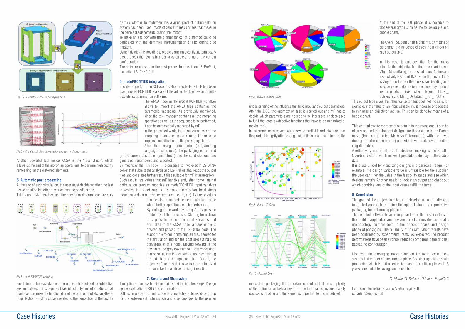
Case Histories35 - Newsletter EnginSoft Year 13 n°3 Case Histories Newsletter EnginSoft Year 13 n°3 - 34
understanding of the influence that links input and output parameters. After the DOE, the optimization task is carried out and mF has to decide which parameters are needed to be increased or decreased to fulfil the targets (objective functions that have to be minimized or maximized).In the current case, several outputs were studied in order to guarantee the product integrity after testing and, at the same time, minimize the
mass of the packaging. It is important to point out that the complexity of the optimization task arises from the fact that objectives usually oppose each other and therefore it is important to find a trade-off.
At the end of the DOE phase, it is possible to plot several graph such as the following pie and bubble charts:
The Overall Student Chart highlights, by means of pie charts, the influence of each input (slice) on each output (pie).
In this case it emerges that for the mass minimization objective function (pie chart legend Min _ MassaBase), the most influence factors are respectively HB4 and Bz2, while the factor Th10 is very important for the back cover bending and for side panel deformation, measured by product instrumentation (pie chart legend FLEX _Schienale and Min _ DeltaDispl _ C _ POST).
This output type gives the influence factor, but does not indicate, for example, if the value of an input variable must increase or decrease to minimize an objective function. This can be done by means of a bubble chart.
This chart allows to represent the data in four dimensions. It can be clearly noticed that the best designs are those close to the Pareto curve (best compromise Mass vs Deformation), with the lower door gap (color close to blue) and with lower back cover bending (big diameter).Another very important tool for decision-making is the Parallel Coordinate chart, which makes it possible to display multivariable data. It is a useful tool for visualizing designs in a particular range. For example, if a design variable value is unfeasible for the supplier, the user can filter the value in the feasibility range and see which designs remain. Another use is to look at an output and check out which combinations of the input values fulfill the target.
8. ConclusionThe goal of the project has been to develop an automatic and integrated approach to define the optimal shape of a protective packaging for an home appliance.The selected software have been proved to be the best-in-class in their field of application and now are part of a innovative automatic methodology suitable both in the concept phase and design phase of packaging. The reliability of the simulation results have been confirmed by experimental tests. As expected, the product deformations have been strongly reduced compared to the original packaging configuration.
Moreover, the packaging mass reduction led to important cost savings in the order of one euro per piece. Considering a large scale production which is estimated to be close to a million pieces in 3 years, a remarkable saving can be obtained.
C. Martin, G. Bolla, A. Ortalda - EnginSoft
For more information: Claudio Martin, EnginSoft [email protected]
Fig.8 - Overall Student Chart
Fig.9 - Pareto 4D Chart
Fig.10 - Parallel Chart
Another powerful tool inside ANSA is the “reconstruct”, which allows, at the end of the morphing operations, to perform high quality remeshing on the distorted elements.
5. Automatic post processingAt the end of each simulation, the user must decide whether the last tested solution is better or worse than the previous one.This is not trivial task because the maximum deformations are very
small due to the acceptance criterion, which is related to subjective aesthetic defects; it is required to avoid not only the deformations that could compromise the functionality of the product, but also aesthetic imperfection which is closely related to the perception of the quality
by the customer. To implement this, a virtual product instrumentation system has been used, made of zero stiffness springs that measure the panels displacements during the impact.To make an analogy with the biomechanics, this method could be compared with the dummies instrumentation of ribs during side impacts.Using this trick it is possible to record some macros that automatically post process the results in order to calculate a rating of the current configuration.The software chosen for the post processing has been LS-PrePost, the native LS-DYNA GUI.
6. modeFRONTIER integrationIn order to perform the DOE/optimization, modeFRONTIER has been used. modeFRONTIER is a state of the art multi-objective and multi-disciplines optimization software.
The ANSA node in the modeFRONTIER workflow allows to import the ANSA files containing the parametric packaging. As previously mentioned, since the task manager contains all the morphing operations as well as the sequence to be performed, it can be automatically managed by mF.In the presented work, the input variables are the morphing operations, so a change in the value implies a modification of the packaging shape.After that, using some script (programming language instructions), the packaging is mirrored
(in the current case it is symmetrical) and the solid elements are generated, renumbered and exported.By means of the “sh node” it is possible to invoke both LS-DYNA solver that submits the analysis and LS-PrePost that reads the output files and generates further result files suitable for mF interpretation.Such results are values that mF handles and, after some internal optimization process, modifies as modeFRONTIER input variables to achieve the target outputs (i.e mass minimization, local stress reduction and spring displacements reduction, etc). Extracted values
can be also managed inside a calculator node where further operations can be performed.By looking at the workflow in fig 7, it is possible to identify all the processes. Starting from above it is possible to see the input variables that are linked to the ANSA node; a transfer file is created and passed to the LS-DYNA node. The support file folder, containing all files needed for the simulation and for the post processing also converges at this node. Moving forward in the flowchart, the grey box named “PostProcessing” can be seen, that is a clustering node containing the calculator and output template. Output, the objective functions that have to be to minimized or maximized to achieve the target results.
7. Results and DiscussionThe optimization task has been mainly divided into two steps: Design space exploration (DOE) and optimization. DOE is important for mF since it constitutes a basis data group for the subsequent optimization and also provides to the user an
Fig.5 - Parametric model of packaging base
Fig.6 - Virtual product instrumentation and spring displacements
Fig.7 - modeFRONTIER workflow

Newsletter EnginSoft Year 13 n°3 - 36 Case Histories37 - Newsletter EnginSoft Year 13 n°3 Case Histories
S.A.T.E. S.r.l. (Venice, Italy) performed a Transient/Dynamic Response Study of a compression facility including four parallel trains (each train of four stages) on behalf of ENAR Pvt Ltd. This facility is located within the QADIRPUR gas field, one of the major gas reserves of Pakistan, operated by OGDCL, and compresses the permeate gas produced by one of the largest ever built membrane plants for CO2 and water vapor separation. The development was performed as part of a major upgrade to manage a larger flow capacity. The study was needed to check which problems might arise when integrating different compressors from various original equipment manufacturers (OEM) in the same installation to operate concurrently at several combinations of working trains.ENAR, acting as the detailed engineering contractor for the compression facility, provided all as built data of compressor, piping, valves data and drawings to S.A.T.E. for the model development. Moreover they exchanged comments and OEMs’ agreements regarding the analysis outcomes and finally reviewed S.A.T.E. report with respect to existing machines, configuration and design constraints.S.A.T.E. simulated and analyzed several operational transient, verified and tuned the antisurge valves (ASV) size and controllers and the response of the performance and load sharing controllers.
Complex dynamic and control interactions were identified. The key element of the analysis was S.A.T.E.’s qualified COMPSYS™ simulation software environment, which allowed accurate simulation of the complex interactions among the sixteen centrifugal machines, their drivers, the plant and the controls.
Scope of the Transient Dynamic SimulationThe dynamic simulations regarded the study of the transient operation of four compression trains driven by as many gas turbines (Figure 1), working in parallel, all or in part, during normal and emergency operations. The two existing trains, compressors and gas turbines were supplied by GE-Nuovo Pignone (Italy, OEM1), the two other trains were supplied by MAN Turbo GmbH (Germany, OEM2).The total gas flow rate delivered by operating all four trains is approximately 140000 Sm3/h, for a total power of approximately 40 MW to compress a mixture of mainly methane and carbon dioxide from ca 1 to 62 bar absolute.The complexity of this large plant (over 2500 m and 840 m3 of piping) required a huge work, including data collection and preprocessing, checking of consistencies and setup of synthetization criteria, because the various signals all had relevance to the results. Also the model build up required a record amount of memory during
simulations, as huge numbers of output signals were generated, along with over 2000 state variable.The total number of runs delivered to cover the entire scope of work was over 100.
Main Simulation ResultsSteady states in open loopOpen loop steady state simulations were performed to identify a reference stable operating condition of the plant and compare the dynamic simulation study (DSS) results with the heat and material balance (H&MB). For the OEM2 train (running at normal
Simulation of Large Compression Plants Transients
Stage 1 Stage 2 Stage 3 Stage 4
TRAIN 1 (EXISTING)
TRAIN 2 (EXISTING)
TRAIN 4 (NEW)
TRAIN 3 (NEW)
Fig. 1 - Outline of the gas compression plant simulated
condition) the simulated plant presented few percent deviations from the H&MB at the nominal 1st stage compressor speed. This was very acceptable for the purpose of the DSS.The OEM1 trains (running at operating conditions and at the nominal speed value) would have been in surge conditions if the ASVs were fully closed. Therefore, partial ASV opening was necessary to find stable steady states. This surprisingly anomalous situation supported reports from the field by ENAR and OGDCL operators.
Controllers tuning The first dynamic series of simulations were performed to tune the gains of the anti surge controller (ASC). In comparison to the OEM2 trains, it was found that higher margins from the nominal surge limit line were necessary for the OEM1 trains to avoid surge phenomena. With the usual margin of 10%, the ASC would work in an unstable
compressor map zone and could not prevent surge. Figure 2 presents an example map of one stage of the OEM1 compressor. The blue line represents the surge limit line (SLL); the red shows the common 10% margin from SLL; the green notes the 25% margin from SLL. The compressor curves, between the surge line and the one with a margin of 10%, present nearly no slope, thus inducing an intrinsic instability as the operating point moves fast rightwards, even after a low discharge depressurization by a small opening of the ASV and vice versa. The ASC had therefore a very high gain in open loop mode, which then yielded instability in closed loop. Considering the myriad situations that can arise during the field tuning, it was concluded that a margin of 25% from the SLL, for the first stage, and 20% for the other stages, had to be implemented for the ASC of the OEM1 trains. This is particularly important when coupled with the new compressors by OEM2.
Additionally, a slightly higher margin than usual was required for the OEM2 trains. 15% (instead of 10%) was needed for all the four stages instead in order to achieve stable operation, given the significant interaction among the four stages. After the tuning of the ASC, the performance controller (PC) was implemented. Here, the plant provided the imposed value of mass flow rate and, alternatively or concurrently, maintained the imposed pressure in the suction header. Furthermore, a virtual load sharing (LS) control function was implemented (even if did not exist in the real plant controller) in order to subdivide the load among the running trains, namely the mass flow rate, according to the normal manual control criteria by the operator. The above findings can be applied in multiple situations when new compressors from a different manufacturer need to be added to existing ones. This occurs regularly due to the open competition maintained by oil & gas companies, and also because of the evolution of the plant’s needs, which often dictate that different characteristics of compressors are required at different development phases of the field life.
Start-upThe start up simulations for such a complex compressor plant were undertaken to verify the procedure defined by the client and the OEMs, confirm the correct path of the operating point through the maps of the various stages, prior and after the ASC activation and, finally detail the torque margins of the drivers during the acceleration phase, taking into consideration the summer conditions that yield the least gas turbine power.The start up simulations were performed according to the procedure specified by the client for a typical normal condition. Several runs were executed to analyze the behavior of the plant while one train is starting, respectively with zero, one, two or three train(s) running.
No anomalous conditions (no surge or instabilities), were observed during the sequence. One interesting result was that the two sets of compressors took different times to achieve the discharge pressure and the target mass flow rate (Figure 3). Moreover the large discharge piping, which totalled approximately 30 m3, took a long time to be pressurized by the compressors of the last stages. This induced the operating points to go beyond the stone wall line due to the low compressor ratio corresponding to the delivered flow rate. For example, the third and fourth stages of the OEM2 compressors enter the stone wall zone in the higher part of the speed range, reaching a correct operating point only after the speed up ramp end, when their ASVs close (Figure 4). Furthermore, when simulating the startup of one train while others were running, there was an interaction between the starting and the running trains. This induced some small oscillations that were extinguished when the plant reached a balanced flowing condition.Another parameter monitored in the start-up simulations was the higher dynamic pressure in the heat exchangers, which reached temporary peaks of more than twice the nominal values. This is useful for the verification of transient fluid dynamic overload of the heat exchangers during the start up sequence.
Fig. 2 - Example of flat map close to the SLL causing possible ASC instability due to interaction with other controllers and multitrain systems. MCS = Maximum Continuous Speed, MOS = Minimum Operating Speed, NOC = Normal Operating Condition, NS = Normal Speed, SLL = Surge Limit Line
Fig. 3 - Comparison of the discharge pressure rise in the last stage (4th) during startup of a single train: red dotted line OEM1, blue solid line OEM2

Case Histories39 - Newsletter EnginSoft Year 13 n°3
Other simulated scenariosThe simulation runs programme encompassed several other transient scenarios starting from any combinations of running compressors: normal stop, driver emergency shut down (ESD), process disturbances (e.g. the change in suction and discharge pressure or in suction and discharge mass flow rate), emergency and faults operations (e.g. the fail close event of one isolation valve on the suction, interstage or discharge side, or the fail open event of any of the ASV).
ConclusionsThe simulations performed in this Transient/Dynamic Response Study provided many useful results for the plant operator (OGDCL),
the engineering company (ENAR) and the OEM (MAN Turbo) producing the new rotating machines. The independent evaluation by the simulation contractor (S.A.T.E.) of this difficult plant upgrade, which involved the integration of machines of different characteristics, was an essential aid to the end client. It allowed them to induce clear positions from the responsible parties in front of the proven plant and revealed equipment reactions to the simulated operational situations and events.
Simulations can therefore be helpful, not only when making design choices, but also by clarifying the positions of the responsible parties for each item of a complex system supply.
Attilio BrighentiS.A.T.E. Systems and Advanced Technologies Engineering S.r.l.
(Italy-Venice)
Tanveer-ul-HaqueENAR Petrotech Services (Pvt.) Ltd (Pakistan-Karachi)
Note: this article is a reduced and complemented version of the article “Theory in practice”, previously published on Hydrocarbons Engineering, December 2011.
0 0.5 1 1.5 2 2.50
20
40
60
80
100
120
140
160
180
200
Volumetric flow rate
Pol
ytro
pic
head
max inlet T
min inlet T
max outlet T
min outlet T
Fig. 4 - Operating point of the 3rd stage (a - left) and 4th stage (b - right) of the OEM2 compressor during startup
0 0.2 0.4 0.6 0.80
20
40
60
80
100
120
140
160
180
200
Volumetric flow rate
Pol
ytro
pic
head
max inlet T
min inlet T
max outlet T
min outlet T
17th - 18th
OCTOBER2016
PARMAPAGANINI CONGRESSI
ITALY
Put the spotlight on your Research Project
The Research Agorà is the place to be! The value of Research,
the power of Innovation...
join the Research Agorà!WWW.CAECONFERENCE.COM
FOR MORE INFORMATION
Yesterday’s product development process was centered on conventional, well understood materials. Large factors of safety were built into designs, and proof of concept was achieved by repetitive physical prototyping. Material testing was often considered a research or academic activity, and the use of simulation was considered “trendy” and not widespread.Today’s product development, on the other hand, encompasses new materials whose behavior may not yet be completely understood, as well as new production processes which themselves can affect product performance. Goals such as light-weighting are driving product design with a focus on critical design parameters and optimal factors of safety. The use of simulation has become mainstream, with proof of design and digital prototyping leading to fewer and later-stage physical prototypes being required. Failure can be expensive.Dealing with materials in today’s simulation driven product development environment can be difficult. There is a need for accuracy and traceability in material data; data acquired from internet resources may present an unmanaged risk. Modern materials and material data can be complex and not easily understood by design engineers. Converting raw data to material parameters for CAE presents a challenge: data must be processed correctly to ensure the inputs to simulation represent material behavior as accurately as possible.DatapointLabs Technical Center for Materials has a mission to strengthen the materials core of manufacturing enterprises by facilitating the use of new materials, novel manufacturing processes, and simulation-based product development. A whole-process approach is needed to address the role of materials in this context.
Start with the right material dataBegin with accurately measured physical properties of the actual material to be used, taking into account the intended manufacturing process. Advanced testing and measurement techniques may be required to capture data for crash and drop simulations, modeling behavior of complex materials such as rubbers or foams, or assessing creep, fatigue and long-term behavior.
Fit the data to the correct modelOnce the right data is acquired, it must be fitted to a numerical model that translates material behavior into something the simulation software can use. The material model needs to account for the effects to be simulated. Raw data needs to be converted correctly into model parameters, and the material file needs to be complete and formatted correctly to
The Role of Materials in Simulation Driven Product Development
Figure 1 - DatapointLabs is the first commercial laboratory in the US to offer dynamic tensile testing at speeds up to 20 m/s. Dynamic properties are becoming extremely important as fundamental data for product design and R&D, particularly where product safety and reliability considerations are of paramount concern. A high-speed tensile testing machine from Shimadzu, coupled with a Photron SA5 camera that captures up to one million frames per second, allows DatapointLabs to employ non-contact video extensometry to measure data at strain rates as high as 1000/s
Reducing materials risk through testing, modeling, validation, management, and knowledge capture
Figure 2 - Matereality® Software for Materials provides specialized tools for fitting equations and evaluating the quality of fit, as well as CAE Modeler modules to automatically convert material parameters for supported CAE and FEA packages

Software Update Newsletter EnginSoft Year 13 n°3 - 40
run in the intended simulation program. Model conversion requires the knowledge to understand interrelationships among material properties and how the various models work together to accurately simulate the target manufacturing process.
Perform a mid-stage validation Using simulation to make design decisions has created a need for greater simulation accuracy. To understand the effect of variables such as solver fidelity, choice of material model, material data quality, and parameter conversion, engineers may choose to perform a validation prior to use in real product simulations.A CAETestBench™ validation quantifies the effect of the inputs to a simulation using carefully controlled physical tests that can be simulated with precision. The tests utilize standardized parts containing geometric features that probe the accuracy of the simulation. An objective measure of accuracy can be obtained by comparing experimental strain fields obtained from the physical test against the simulation of that test.
Strive for consistent, error-free export of material data to the simulation environmentMaterials information is needed by engineering teams at many phases of the product life cycle. A simulation-driven product development environment makes it vital that engineers use real
material data before their products become real. Complex material data must be gathered from reliable sources with knowledge not only of the specific test that is being performed but also a collective view of the required data as a whole when considering simulation-driven product development. The data must be uniform, controlled and traceable, readily accessible, and consumable by simulation solvers and other external processes that need materials information, ideally supported by an enterprise-wide materials knowledge core.With accurate material properties data, as well as properly evaluated and well fit material models, the objective of achieving an accurate simulation becomes much more feasible. The materials experts at DatapointLabs Technical Center for Materials have been serving material inputs for leading CAE solvers for over two decades. We now offer a range of services and software that facilitate all interactions with materials information across the product life cycle.
About the AuthorHubert Lobo is the founder and president of DatapointLabs Technical Center for Materials and its software partner, Matereality. DatapointLabs Technical Center for Materials provides expert material testing, material parameter conversion and model validation services for CAE and FEA, allowing companies to populate their databases with high-quality, application-ready data for design and
new product development. Matereality® Software for Materials gives companies the means to build databases to store properties, CAE material files, and material information on any material. The built-in suite of web-based software helps engineers visualize and understand material data, create CAE models and manage materials information. We help companies build enduring data collections that accurately represent the materials used in their products.CAETestBench is a trademark of DatapointLabs, LLC. Matereality is a registered trademark of Matereality, LLC.
Hubert Lobo, DatapointLabs Technical Center for Materials
For more information: Nicola Gramegna, [email protected]
Software Update41 - Newsletter EnginSoft Year 13 n°3
Figure 3 - Crash validation by CAETestBench
Figure 4 - Collect viable material data into master material files, using consistent terminology across the enterprise, and ensuring that all users access the same master material files
The latest ANSYS Release 17.2 expands multiphysics coupling capabilities and interoperability with Simulation Engineering Tools. It’s now possible to combine advanced simulation technology across the portfolio or enlist external tools to address the complex engineering challenges for smart and connected products.ANSYS 17.2 offers a wealth of new functionality, including enhanced multiphysics coupling, new workflows for antenna design and automated temperature characteristics for electric machines. The deep integration of ANSYS simulation technologies within Workbench platform allows simulation experts to work together and to apply the simulation best practices from concept to detailed design.The main keywords of this release are “customization” and “integration”: the right way to make the customer’s individual work available to the global decision process, significantly reducing development costs and time to market.ANSYS AIM: New Features, Thermal Management and Improved Collaboration ANSYS AIM provides a broad range of physics within an easy-to-use, intuitive and guided workflow. Based on upfront simulation approach, ANSYS AIM improves the productivity of design engineers optimizing product’s lifecycle and minimizing the need for redesign. In ANSYS AIM 17.2 the following new simulation features have been introduced: thermal transient and structural multistep analysis, bolt pretension, cyclic symmetry, momentum and heat sources, wall roughness, strain-dependent viscosity, polymer extrusion thermal effects, and much more. Mission and Safety Critical Applications with ANSYS Model Based Software Development ANSYS Model Based Software Development technologies increase the simulation reliability according to certification standards for safety critical applications in the automotive,
railway, aerospace and energy industries. ANSYS 17.2 now supports Ada certified code generation to meet DO178C, IEC 61508, EN 50128 and ISO 26262 requirements. Moreover, improved links to IBM DOORS and Dassault Systèmes Reqtify requirements management tools enable ANSYS SCADE solutions to be easily incorporated into existing workflows.Upfront Electric Machine and Electromechanical DesignANSYS Maxwell/ANSYS Icepak interface helps the electrical machine designers to evaluate cooling strategies faster. The ANSYS RMxprt TM electrical machine synthesis tool can now output the geometry and temperature characteristics of materials used in the design, avoiding the need to manually add temperatures before running Icepak.Antenna Design and Large 3D Field SimulationsANSYS 17.2 provides new advanced tools for antenna design and
placement, including a streamlined interface between ANSYS HFSS and ANSYS HFSS SBR+ (formerly Savant). Through this interface it’s possible to import the HFSS antenna models into the HFSS SBR+ to exploit advanced shooting and bouncing ray solver to validate antenna design and placement.
For more information:Fabio Rossetti, [email protected]
Highlights on new ANSYS Release 17.2
Figure 1 - Transient structural simulation of an automotive suspension in ANSYS AIM 17.2
Improve Accuracy and Productivity for Next-Generation Product Development
Figure 2 - High Frequency FEM analysis on Human Head with ANSYS HFSS
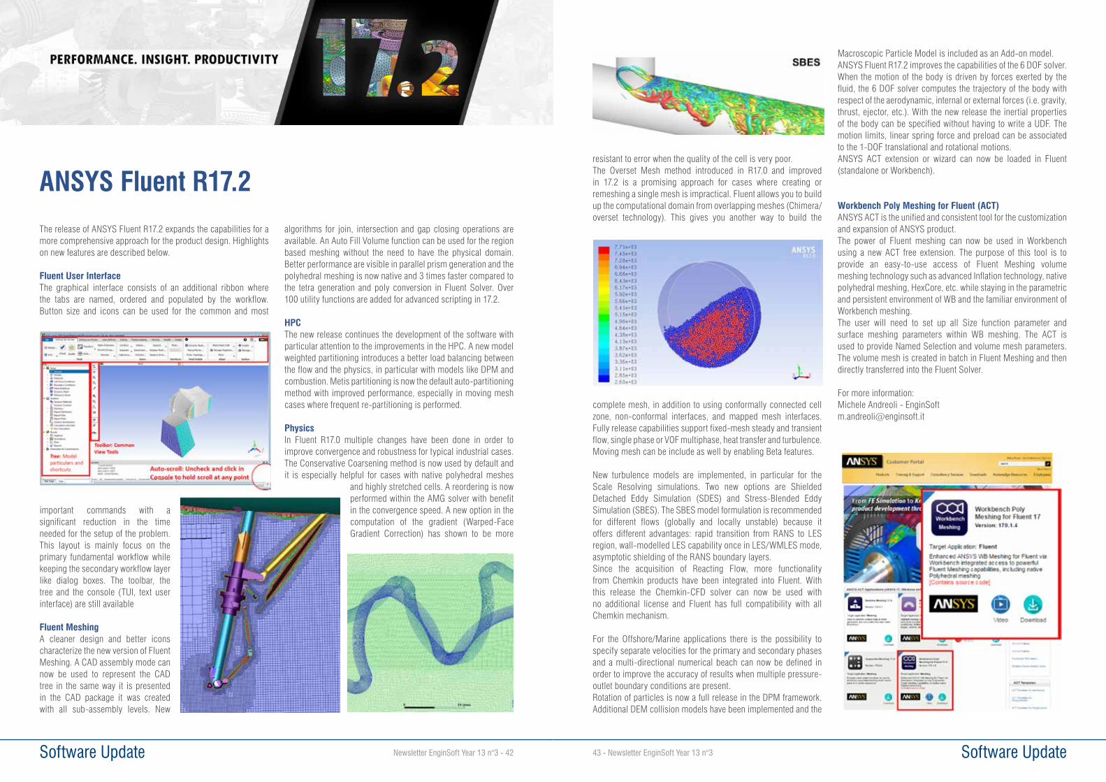
Software Update43 - Newsletter EnginSoft Year 13 n°3 Software Update Newsletter EnginSoft Year 13 n°3 - 42
resistant to error when the quality of the cell is very poor. The Overset Mesh method introduced in R17.0 and improved in 17.2 is a promising approach for cases where creating or remeshing a single mesh is impractical. Fluent allows you to build up the computational domain from overlapping meshes (Chimera/overset technology). This gives you another way to build the
complete mesh, in addition to using conformally connected cell zone, non-conformal interfaces, and mapped mesh interfaces. Fully release capabilities support fixed-mesh steady and transient flow, single phase or VOF multiphase, heat transfer and turbulence. Moving mesh can be include as well by enabling Beta features.
New turbulence models are implemented, in particular for the Scale Resolving simulations. Two new options are Shielded Detached Eddy Simulation (SDES) and Stress-Blended Eddy Simulation (SBES). The SBES model formulation is recommended for different flows (globally and locally unstable) because it offers different advantages: rapid transition from RANS to LES region, wall-modelled LES capability once in LES/WMLES mode, asymptotic shielding of the RANS boundary layers.Since the acquisition of Reacting Flow, more functionality from Chemkin products have been integrated into Fluent. With this release the Chemkin-CFD solver can now be used with no additional license and Fluent has full compatibility with all Chemkin mechanism.
For the Offshore/Marine applications there is the possibility to specify separate velocities for the primary and secondary phases and a multi-directional numerical beach can now be defined in order to improve the accuracy of results when multiple pressure-outlet boundary conditions are present. Rotation of particles is now a full release in the DPM framework. Additional DEM collision models have been implemented and the
Macroscopic Particle Model is included as an Add-on model.ANSYS Fluent R17.2 improves the capabilities of the 6 DOF solver. When the motion of the body is driven by forces exerted by the fluid, the 6 DOF solver computes the trajectory of the body with respect of the aerodynamic, internal or external forces (i.e. gravity, thrust, ejector, etc.). With the new release the inertial properties of the body can be specified without having to write a UDF. The motion limits, linear spring force and preload can be associated to the 1-DOF translational and rotational motions.ANSYS ACT extension or wizard can now be loaded in Fluent (standalone or Workbench).
Workbench Poly Meshing for Fluent (ACT)ANSYS ACT is the unified and consistent tool for the customization and expansion of ANSYS product. The power of Fluent meshing can now be used in Workbench using a new ACT free extension. The purpose of this tool is to provide an easy-to-use access of Fluent Meshing volume meshing technology such as advanced Inflation technology, native polyhedral meshing, HexCore, etc. while staying in the parametric and persistent environment of WB and the familiar environment of Workbench meshing.The user will need to set up all Size function parameter and surface meshing parameters within WB meshing. The ACT is used to provide Named Selection and volume mesh parameters. The volume mesh is created in batch in Fluent Meshing and then directly transferred into the Fluent Solver.
For more information:Michele Andreoli - [email protected]
The release of ANSYS Fluent R17.2 expands the capabilities for a more comprehensive approach for the product design. Highlights on new features are described below.
Fluent User InterfaceThe graphical interface consists of an additional ribbon where the tabs are named, ordered and populated by the workflow. Button size and icons can be used for the common and most
important commands with a significant reduction in the time needed for the setup of the problem. This layout is mainly focus on the primary fundamental workflow while keeping the secondary workflow layer like dialog boxes. The toolbar, the tree and the console (TUI, text user interface) are still available
Fluent MeshingA cleaner design and better icons characterize the new version of Fluent Meshing. A CAD assembly mode can now be used to represent the CAD tree in the same way it is presented in the CAD package it was created with all sub-assembly levels. New
algorithms for join, intersection and gap closing operations are available. An Auto Fill Volume function can be used for the region based meshing without the need to have the physical domain. Better performance are visible in parallel prism generation and the polyhedral meshing is now native and 3 times faster compared to the tetra generation and poly conversion in Fluent Solver. Over 100 utility functions are added for advanced scripting in 17.2.
HPCThe new release continues the development of the software with particular attention to the improvements in the HPC. A new model weighted partitioning introduces a better load balancing between the flow and the physics, in particular with models like DPM and combustion. Metis partitioning is now the default auto-partitioning method with improved performance, especially in moving mesh cases where frequent re-partitioning is performed.
Physics In Fluent R17.0 multiple changes have been done in order to improve convergence and robustness for typical industrial cases. The Conservative Coarsening method is now used by default and it is especially helpful for cases with native polyhedral meshes
and highly stretched cells. A reordering is now performed within the AMG solver with benefit in the convergence speed. A new option in the computation of the gradient (Warped-Face Gradient Correction) has shown to be more
ANSYS Fluent R17.2

Newsletter EnginSoft Year 13 n°3 - 44 Software Update45 - Newsletter EnginSoft Year 13 n°3 Software Update
At the end of August 2016 ANSYS announced the availability of its industry-leading engineering simulation solution: ANSYS 17.2. Profiting by this release the document below takes stock of some new features present in the 17.X releases of ANSYS Maxwell.
Maxwell Integration to ANSYS Electronics DesktopWith the ANSYS 17.X releases Maxwell joined the brand new Electronic Desktop that is the premier, unified platform for electromagnetic, circuit and system simulation. Along with ANSYS Maxwell even other gold-standard tools like ANSYS HFSS, Q3D Extractor, and Simplorer are built natively in the Electronics Desktop, which serves as a universal Pre/Post processor for these tools. Practically this interface looks similar to the previous Maxwell interfaces and old users would find it very familiar.In Figure 1 the Electronic Desktop is depicted.
Time Decomposition Method for Electromagnetic Finite Element AnalysisANSYS 17 can be defined as a historic passage, for its greater power, fastness and focus of performances and innovation; it represents a vertical evolution still called “10X” thanks to significant improvements on different topics. 10X as the time reduction for modeling and configuration of FEM models, 10X as reduction of CPU time, management of big models and improvement of multiphysics interaction. With regard to reduction in time solution ANSYS implements in Maxwell 17.0 a new time decomposition method to significantly speed up magnetic transient simulations.The new Time Decomposition Method for ANSYS Maxwell delivers game-changing computational capacity and speed for full transient electromagnetic field simulation. This patent-pending technology allows engineers to solve all time steps simultaneously instead of sequentially and to distribute the time steps across multiple cores, networked computers and compute clusters. Traditional sequential transient will solve time step 1 by assembling the
T1 matrix, solver it, then move on to time step 2 and so on. The RAM used corresponds to the size of the T1 matrix.TDM does it differently. All the T1, T2, …, T(k) matrices are assembled to form a super ‘matrix’ so that all the time steps are solved altogether.The off diagonal terms in this super matrix correspond to the information that needed to be passed from one time step to another one (electrical quantities, eddy currents …).Once the ‘super’ matrix is built, the matrix is solved over a set of computers/cores. This operation corresponds to solve time steps over different machines at the same time.When solving these time steps on a machine, the user can also benefit from Multi Processing.So the first level of parallelism is done using MPI (Message Passing Interface which is a communication standard for parallel processing), and the second level of parallelism is achieved using Multi-processing for individual tasks. The result is a dramatic increase in simulation capacity and unprecedented simulation speed.In Figure 2 the main concepts that describe this method are depicted.
Fast steady-state transientANSYS Maxwell now converges to steady state much more quickly. For transient simulations whose winding excitations are an AC voltage source, the DC flux linkage component may take a very long time to decay, especially for a device with a large time constant. Selecting the new function Fast Reach Steady State adds an additional voltage component to the original voltage definition during the first half-cycle to quickly eliminate the DC flux linkage, thus speeding up the solution process. It’s possible to provide a frequency of added voltage source value that is greater than zero. This frequency value is applied to all winding voltage sources.This new capabilities is applicable for all types of transient applications and can be combined with Time Decomposition Method. In Figure 3 a
ANSYS Maxwell 17.2
Fig. 1 - ANSYS Electronics Desktop
Fig. 2 - Time Decomposition Method in summary
comparison between current reports either using or not fast stead-state capability is depicted.
Magnetic Harmonic (Eddy Current) Solver EnhancementsWith ANSYS Maxwell 17 the eddy current solver benefits of several improvements, in particular the below features are finally implemented:
• Nonlinear ferromagnetic material support • Winding configuration support with voltage
or external circuit excitation capabilities
These capabilities increase the scopes of the eddy current solver to those analysis where motion is not needed, as the ones to simulate electric transformers and inductors. In Figure 4 the B field solution output of an eddy current solver simulation analysis is depicted.
Enhanced flow for Magnetization and DemagnetizationIn ANSYS Maxwell 17.0 a new flow for magnetization and demagnetization analysis is implemented. The new magnetization flow allows users to:• Magnetize a magnet in its actual magnetizer setup• Reuse multiple instances of this magnet in a different designThe new demagnetization flow allows users to:• Calculate demagnetization of a permanent magnet in a particular
design• Reuse multiple instances of this magnet in a different design Magnetization and demagnetization analysis can be implemented in both static and transient simulations. When the source solution in terms of magnetic properties is passed from a source design to a target design the models involved can have different geometries and occupy different locations.The described capabilities are based on the 2D/3D Vector Hysteresis Modeling implemented in Maxwell.
New Electric Machine Design CapabilitiesNew capabilities have been introduced specifically for the simulation of electric machines. Below the most significant.
1. Multi-slice support in 2D transient solverThis capability allows to solve an electric machine with skewed rotor using several 2D cross-section slices in Maxwell 2D transient design. The user just needs to specify the Skew Angle of the machine as well as the number of slices. Maxwell will solve all slices and recombine the results.
2. Electric Machine Eccentricity ModelingSince 17.1 release, Maxwell has introduced a model to simulate rotor eccentricity with 2D and 3D transient designs that have cylindrical rotational motion set up. The magnetic forces calculated by the transient solution and depending on the eccentricity can be exported to ANSYS Mechanical to compute vibration and noise analysis. The Figure 5 illustrates the wizard at user disposal to implement the eccentricity simulation.
3. Multi motion support in 2D transientWith ANSYS Maxwell 17, by means of the 2D transient solver, user can assignee two or more motion bands , each with its own independent motion characteristics. Multiple motion bands are used primarily for certain types of motors where multiple rotors may rotate about a common central axis.
4. Automatic link generation from Maxwell-RMxprt to Icepak.To perform a thermal CFD analysis of an Electric Engines is possible to link a model done in RMxprt and Maxwell to ANSYS Icepack. The link includes: geometry generation; mesh control definition; boundary and excitation definition; creating CFD transient settings.This capability is available since Maxwell 17.2 release.
5. ANSYS Maxwell co-simulation with Simulink.In addition to using either the Maxwell Circuit Editor to set up an external circuit, or the cosimulation with ANSYS Simplorer, Matlab® Simulink® can be used to set up an external circuit feeding both Maxwell 2D and 3D transient designs.
For more information: Emiliano D’Alessandro, [email protected]
Fig. 3 - Transient Fast Reach Steady State: current report Fig. 4 - Saturation study of the core of an electric transformer by means of the Maxwell magnetic harmonic solver
Fig. 5 - ANSYS Maxwell eccentricity wizard

Newsletter EnginSoft Year 13 n°3 - 46 Software Update47 - Newsletter EnginSoft Year 13 n°3 Software Update
EnginSoft is more and more customers’ partner for product and competitive advantage development. In addition to its wide expertise and decades of experience in the field of electromagnetics, EnginSoft is NOW ANSYS Channel Partner for high frequency electronics and electromagnetic products.ANSYS Electronics solutions help to design innovative electronic and wireless products faster and more efficiently. Through electromagnetic, circuit, systems and multi-physics simulations the design process is fully automated, in order to provide engineers an overall complete view of product behavior. On the other hand, the high specificity of each tool allows designers to revise and modify any detailed technical aspect at each stage of product development.
ANSYS Electronic DesktopANSYS Electronics Desktop is an unified comprehensive platform for electromagnetic, circuit and system simulation and serves as a universal Pre/Post processor for the family tools . The Solver on Demand technology enables the combination of electromagnetic simulators with circuit- and system-level analysis to explore full system performance. ANSYS Electronics Desktop products support both Python and Visual Basic scripting. Latest capabilities enable to design, optimize and share high-frequency components across engineering departments and throughout the supply chain. Thus leveraging component IP at higher levels of integration to streamline design by providing full 3-D accuracy to multiscale assemblies. Electronics Desktop products link to ANSYS Workbench for full multi-physics simulation and optimization under real-world physical conditions.
ANSYS HFSS - High Frequency Electromagnetic Field SimulationANSYS HFSS software is the industry standard for simulating 3-D, full-wave, electromagnetic fields. Its unique accuracy, advanced solvers and high-performance computing technologies make it an essential tool for engineers tasked with executing accurate and rapid design in high-
frequency and high-speed electronic devices and platforms. HFSS offers state-of the-art solver technologies based on Finite Element Method (FEM), the large scale Method of Moments (MoM) technique, and ultra-large scale asymptotic methods of Physical Optics (PO) and Shooting and Bouncing Rays plus (SBR+). When combined with ANSYS HPC technology, rigorous multi-solver hybrid techniques deliver advanced multi-scale, multi-fidelity computational electromagnetics available in an easy-to-use design environment. With HFSS, engineers can reliably extract SYZ parameters, visualize 3-D electromagnetic fields, and generate component models to evaluate signal quality, transmission path loss, impedance mismatch, parasitic coupling and far-field radiation. By leveraging a sophisticated and proprietary automatic adaptive meshing technology, HFSS provides accurate and reliable solutions to the most difficult electromagnetic simulation challenges.Through the HFSS Transient Solver, engineers can directly simulate transient electromagnetic field behavior and visualize fields or system responses in applications such as Time Domain Reflectometry (TDR), Ground-Penetrating Radar (GPR), ElectroStatic Discharge (ESD), Electromagnetic Interference (EMI) and lightning strikes.The HFSS Shooting and Bouncing Ray Plus (SBR+) technique, based on advanced physics models such as creeping waves, UTD diffraction rays and surface curvature extraction, allows advanced antenna performance simulation and provides fast and accurate prediction of installed antenna patterns, near-fields and antenna-to-antenna coupling on electrically large platforms. HFSS SBR+ analyzes installed antenna performance on
The EnginSoft High Frequency Electromagnetic side
Figure 1 - Multiple and connected simulations in ANSYS Electronics Desktop
Figure 2 - Printed circuit board is assembled with chip antenna and connector 3-D components into a full assembly for simulation.
platforms that are tens to thousands of wavelengths in size.With the HFSS hybrid FE-BI technology antenna designers can realize increased accuracy for radiated far-field solutions involving antenna platform integration.The HFSS Planar EM Solver is ideal for engineers designing RF and wireless circuits and planar antennas such as LTCC, MMIC, RFIC, RFID, IC and PCB structures. PlanarEM is a 2.5-D (Method of Moments) field simulation tool that provides dynamic parametric co-simulation for S-, Y-, and Z-parameters and for local current as well as near- and far-field radiation analyses.
ANSYS SIwaveANSYS SIwave is a specialized design platform for Power Integrity, Signal Integrity and EMI analysis of electronic packages and PCBs. The SIwave-DC product targets DC analysis of low-voltage, high-current PCBs and IC packages, enabling assessment of critical end-to-end voltage margins
to ensure reliable power delivery. It allows to perform pre- and post-layout “what-if” analyses for DC voltage drop, DC currents and DC power loss. SIwave performs fast Zo and cross-talk scanning with visual, color-coded feedback and HTML reports. SIwave-PI computes resonances, reflections, inter-trace coupling, simultaneous switching noise, power/ground bounce, DC voltage/current distributions, and near- and far-field radiation patterns on high-speed PCBs and complex IC packages, in
order to run SSO analysis, impedance matching, power delivery system optimization, IBIS analyses, such as power-aware IBIS and IBIS-AMI, to provide virtual compliance.SIwave links to the ANSYS software portfolio for multiphysics simulation of electronic components. One option is to export a power distribution
map from SIwave into ANSYS Icepak. This multiphysics solution enables accurate thermal modeling of IC packages and PCBs using DC power loss from SIwave as a heat source. Icepak solves the challenges associated with dissipation of thermal energy from electronic components that may cause premature component failure due to overheating. In order to evaluate thermal stress with ANSYS Mechanical. This multiphysics approach enables
engineers and design teams to perform coupled EM–thermal–stress analysis for a complete understanding of the design.The SIwave GUI has several Add-On solver technologies, such as the Sentinel-PSI solver and the ANSYS Q3D Extractor solver, which enables streamlined analyses for 3-D Package Power Integrity and 3-D Quasi-static parasitic extraction of packages and PCBs. SIwave imports
Figure 3 - Antenna on large scale aircraft
Figure 4 - Fields through PCB via as solved with HFSS transient
Figure 5 - Differential signal propagating in time through a flexed cable solved with HFSS transient using conformal finite elements
Figure 6 - HFSS SBR+ allows field evaluation on large scale platform and systems
Figure 7 - 3-D far-field gain patterns for VHF (tail) and UHF (underside) antennas showing modulation due to motion of rotors
Figure 8 - 16 by 16 antenna array solved with Planar EM solver

49 - Newsletter EnginSoft Year 13 n°3 Software Update Newsletter EnginSoft Year 13 n°3 - 48 Software Update
ECAD files from well-known ECAD providers such as Altium, Autodesk, Cadence, Mentor Graphics and Zuken. SIwave seamlessly transfers data to different physics solvers such as ANSYS Icepak for thermal design and ANSYS Mechanical for structural analysis within ANSYS Workbench.
ANSYS Q3D Extractor ANSYS Q3D Extractor is the premier 2-D and 3-D parasitic extraction tool for engineers designing electronic packages, touchscreens and power electronic converters. Q3D Extractor performs electromagnetic field simulations and results include proximity and skin effect, dielectric and ohmic loses, and frequency dependencies. Q3D Extractor easily and quickly provides 3-D extraction of resistance (R), partial inductance (L), capacitance (C) and conductance (G) for designing cable harnesses power electronic converters, transformers and bus bars. Transmission line and cabling wizards provide intuitive and easy-to-use interfaces for rapid 2-D prototyping. Q3D couples with ANSYS Mechanical, Fluent and Icepak for inclusion of thermal stresses during design.The ability to generate highly accurate reduced-order SPICE models for use in circuit simulation makes ANSYS Q3D Extractor the ideal software to create IBIS package models. Engineers can study crosstalk, ground bounce, interconnect delays and ringing; this helps them to understand the performance of high-speed electronic designs, such as multilayer printed circuit boards, advanced electronic packages and 3-D on-chip passive components. In addition, Q3D Extractor is essential for extracting
accurate electrical parasitics of critical interconnect components in the package (bondwires), on the board (critical nets), and for the connection path between the chip, package and board (i.e., connectors, cables, sockets and transmission lines).
ANSYS Q3D Extractor is also ideal for designing power electronic equipment used in hybrid-electric technologies and power distribution applications to optimize inverter/converter architectures and minimize bus inductance, overvoltage situations and short-circuit currents. With Q3D Extractor, you can solve design challenges by analyzing the RLCG matrix data of touchscreen devices. Designers can leverage ANSYS Q3D Extractor to create equivalent circuit models (SPICE sub-circuits/ladder-type lumped models). The type of model that Q3D Extractor produces depends on which solver was used. The 2-D and 3-D field solvers create common formats such as Simplorer SML, HSPICE Tabular W-Element, PSpice, Spectre, IBIS ICM/PKG models and ANSYS CPP models.
For more information:Andrea Serra, [email protected]
Optimization involving computational fluid dynamics has become sustainable thanks to the reduction of the costs related to computational resources. Powerful workstations and HPC systems allow to run high fidelity simulations in parallel dramatically reducing computational time. To run multiple designs concurrently and amplify usage of available licenses, ANSYS has introduced the HPC Parametric Pack. The multi-objective optimization software modeFRONTIER, product of ESTECO, supports a direct integration with ANSYS products and, starting from the latest release,, introduces the support to the HPC Parametric Pack.In this presentation, the advantages and the benefits of using modeFRONTIER 2016 coupled with ANSYS are presented. The direct integration enables a user friendly design process creation, avoiding scripting issues. The HPC Parametric Pack option enables to run multiple designs concurrently and results show the significant time savings especially when facing complex industrial problems: successful applications to heat exchangers (Optimhex European Project) and automotive industry (Borgwarner) will be illustrated.
modeFRONTIER interface for ANSYS HPC Multi-objective optimization in an automatic and distributed environment, that allows direct communication between multi-disciplinary simulation software, is more and more becoming a key factor in today’s design process.Traditional design approach (‘trial and error’) usually requires many attempts to the designers, which every time need to modify their numerical models by hand and run several solvers, especially when it is difficult to know a priori in which direction of the multi-dimensional variables space to move in order to find the best solutions. Conversely, the multi-objective design environment modeFRONTIER allows to integrate different computational software (any commercial or in-house code) into a common design environment, thus allowing the automatic execution of a series of designs proposed by a selected optimization algorithm, until the specified objectives are satisfied. In this modular environment, each component of the optimization process, including input variables, input files, scripts or direct interfaces
to run the software, output files, output variables and objectives, is defined as a node to be connected with the other components. In this way, the complete logic flow from parameterization to performance evaluation is defined by the user who can select among several available optimization algorithms accordingly to the objectives defined. These include, Genetic Algorithms, Evolutionary Algorithms, Game Strategies, Gradient-based Methodologies, Response Surfaces (used to speed up the convergence of optimization and to approximate the response of the system made by the available Meta-Models.Most of these methodologies allow the possibility of evaluating concurrent design simulations (for instance, Genetic Algorithms allow to evaluate all the designs which compose a generation at the same time), for instance distributing each design on a different core selected in the network, using a different license key (Fig.1).
Optimization applications involving a large number of concurrent simulations may then arise a problem of software cost: to overcome this problem, ANSYS has recently introduced HPC Parametric Pack, a tool which allows to amplify the number of concurrent evaluations available with a single pack (for instance, 1 Pack allows 4 concurrent evaluations, 2 Packs 8, 3 Packs 16, 4 Packs 32, and so on), therefore allowing a large usage of licenses without an excessive cost.modeFRONTIER has therefore introduced a new option in its ANSYS interface (Fig.2), allowing the possibility of using HPC Parametric Pack, thus running a number of concurrent design simulations up to the number of available license tokens and the number allowed by the selected optimization algorithm.
modeFRONTIER and ANSYS HPC Parametric Pack for highly Efficient Design Optimization for automotive applications
Figure 1 - Usage of ANSYS HPC Parametric Pack in modeFRONTIER optimization software

Software Update Newsletter EnginSoft Year 13 n°3 - 50 Software Update51 - Newsletter EnginSoft Year 13 n°3
Optimization of Heat ExchangersThe first application of HPC presented in this article is an heat exchanger optimization. The object of the optimization is the core of a mixed-flow (air and liquid) heat exchanger (Fig.3). The methodology starts from the design of a single HE Core Element (HECE), which is the smallest “cell” of the HE core that, repeated in the x and y directions of a plane, can generate the entire HE core (fig. 4). It thus represents the fundamental building block of the entire HE. The proposed approach for the simulation of the HECE elements is to evaluate separately air and liquid elements, accordingly to literature, and then to compute the overall performances of the heat exchanger following a ε-NTU method.For the CFD determination of heat transfer and friction factor correlations of HECE elements, we followed the assumption of periodically developed flow and heat transfer. In fact, except for the development length, the flow regime is fully developed inside the liquid or air channels; therefore it is needed to specify periodic conditions at the boundaries of the HECE.
To assure the analysis of a fully developed flow, it is necessary to impose a periodic condition on inlet and outlet surfaces (at left and right of HECE in figure 4) with an imposed massflow, besides the lateral periodic conditions. Once the periodic fluid dynamic analysis is performed, for the periodic thermal analysis we assumed a constant heat flux at the wall, simpler to impose in a commercial CFD code, since it only requires a source term addition in the energy equation.Fig.4 below reports an example of the flow field of an HECE simulation (geometry from Kays & London, Re=500), using the CFD code ANSYS CFX. The proposed approach has been successfully validated, for a given geometry of the staggered-fin channel available from literature (Kays & London 10-56).
An automatic process for the generation of any HECE configuration in function of given geometrical parameters has been set up in modeFRONTIER reports the workflow used for the automatic evaluation of a HECE. The input parameters nodes are directly connected to the parametric CAD interface (CATIA v5), allowing the automatic update of the HECE CAD model (note that in the main process flow, a part of the applications chain is repeated for both air and liquid HECE, by the use of two subprocesses nodes). The geometrical parameters considered for the HECE are: height h, length l, pitch w, pitch ratio wr (ratio between top and bottom pitch, to allow trapezoidal shape of fins besides rectangular ones), angle of fins α (angle of fins w.r.t. flow direction), offset k (staggering of two consecutive rows of fins) and fin thickness t.Once the CAD is updated, the model files are transferred to the following application node, which is the ANSYS Workbench (WB) interface, used for the meshing operations and for the CFD analysis. These analyses (periodic fluid-dynamic and thermal) are actually performed by two separate ANSYS Workbench nodes. In the main workflow, the process chain is then completed by the evaluation of the global performances of the HE, by a Bridge node which implements through a Javascript code the k-ε-NTU method.By the execution of the modeFRONTIER workflow, it is possible to evaluate automatically a series of design configurations, defined by the selected optimization algorithm, until the defined objectives are satisfied.Table below reports the results of the optimization problem considered: The core weight has been reduced by 25%, keeping the cooling power performances (constraint) and minimizing the power losses by 9.
Finally, Fig.5 illustrates the benefits of the HPC Parametric Pack interface of modeFRONTIER, that has been here used for the concurrent evaluations of ANSYS models. Without using this option, each design should be evaluated on a single cpu in sequence, and since 1 design simulation take as average 6:15 hrs, to evaluate just 8 designs it would have taken about 50 hrs (Fig.5). On the other side, using the HPC Parametric Pack interface, we have run 8 designs in parallel, each one on a different core, thus completing all 8 designs in just about 6:15 hrs. For the application described above, the optimal results have been obtained after the evaluation of about 100 designs, that is about 4 weeks; without the HPC Parametric Pack, the time to complete the optimization would have been not acceptable for an industrial application.
Figure 2 - ANSYS interface in modeFRONTIER optimization software
Figure 3 - Core of the mixed-flows heat exchanger to be optimized
Figure 4 - CFD analysis of a generic HECE configuration (velocity and temperature fields)
Applications to automotive industryThe second application of HPC presented in this article is relative to the structural optimization of a tensioner arm of Sports Car. Fig.6 illustrates the CAD model of the component, with indications about applied forces and restraints. The piston contact area is one of the most critical and due to the high load they had plasticity deformation in the baseline solution. The purpose of the optimization is therefore the one to guarantee the satisfaction of maximum stress limits, reducing at the same time the weight of the component. Considering that this is a component of Sports Car, high performance and little volume of production, the main objectives is to guarantee the higher performance as possible.The parametric model of the arm has been realized in ANSYS Workbench, using a mesh of 158k nodes, using a Anticorodal Alluminium alloy. Simulation time of one design takes about 1h 30 m with 8Gb RAM machine. The model has been integrated in modeFRONTIER through the direct ANSYS interface, and an optimization using Genetic Algorithm NSGAII (12 generations x 48 population designs) has been executed, obtaining the results illustrated in Fig. 7.In particular, the bubble chart reports in abscissa the maximum principal stress in the lower part of the tensioner arm, while the ordinates report the one of the upper part, most critical; in addition, mass of the component is represented by the color scale, and the maximum deflection is proportional to the diameters of the bubble.From the Pareto frontier (set of optimal design), the designer has selected as optimal solution the one represented in fig.9, right, in comparison with the baseline represented in the same figure, at left: while keeping practically the same mass of the component (151kg), the maximum
stress in the most critical area (upper side) has been reduced from 90.9 MPa to 62. MPa.It is worth to note that these results have been obtained using the ANSYS HPC Parametric Pack option of modeFRONTIER, allowing to simulate (using 4-cores) a total of 576 designs in 10 days, instead of 36 days if every single simulation would have been run sequentially.
ConclusionsThis article has illustrated the benefits of the integration of ANSYS HPC Parametric Pack with modeFRONTIER optimization software, by the application to two industrial
optimization cases (heat exchangers and automotive components). The results obtained (mass reduction, power losses reduction, constraints satisfaction) have proved the efficiency of the optimization methodology, and the HPC Parametric Pack option has made feasible the task both in terms of overall time and of license costs.
AcknowledgementsThe research leading to the heat exchanger results has gratefully received funding from Eurostars Programme powered by EUREKA and the European Community (http://www.eurostars-eureka.eu/). For the automotive application, the author would like to thank Borg Warner Morse system and EnginSoft, which have developed the project.
Alberto Clarich - ESTECO , Francesco Franchini, EnginSoft
For more information: Francesco Franchini, [email protected]
Figure 5 - Usage of HPC in terms of time: sequential (above) and concurrent (below) executions
Table 1 - Optimization results
Figure 6 - Tensioner arm model (boundary conditions)
Figure 7 - Optimization results
Figure 9 - Original configuration (left) and optimized one (right)
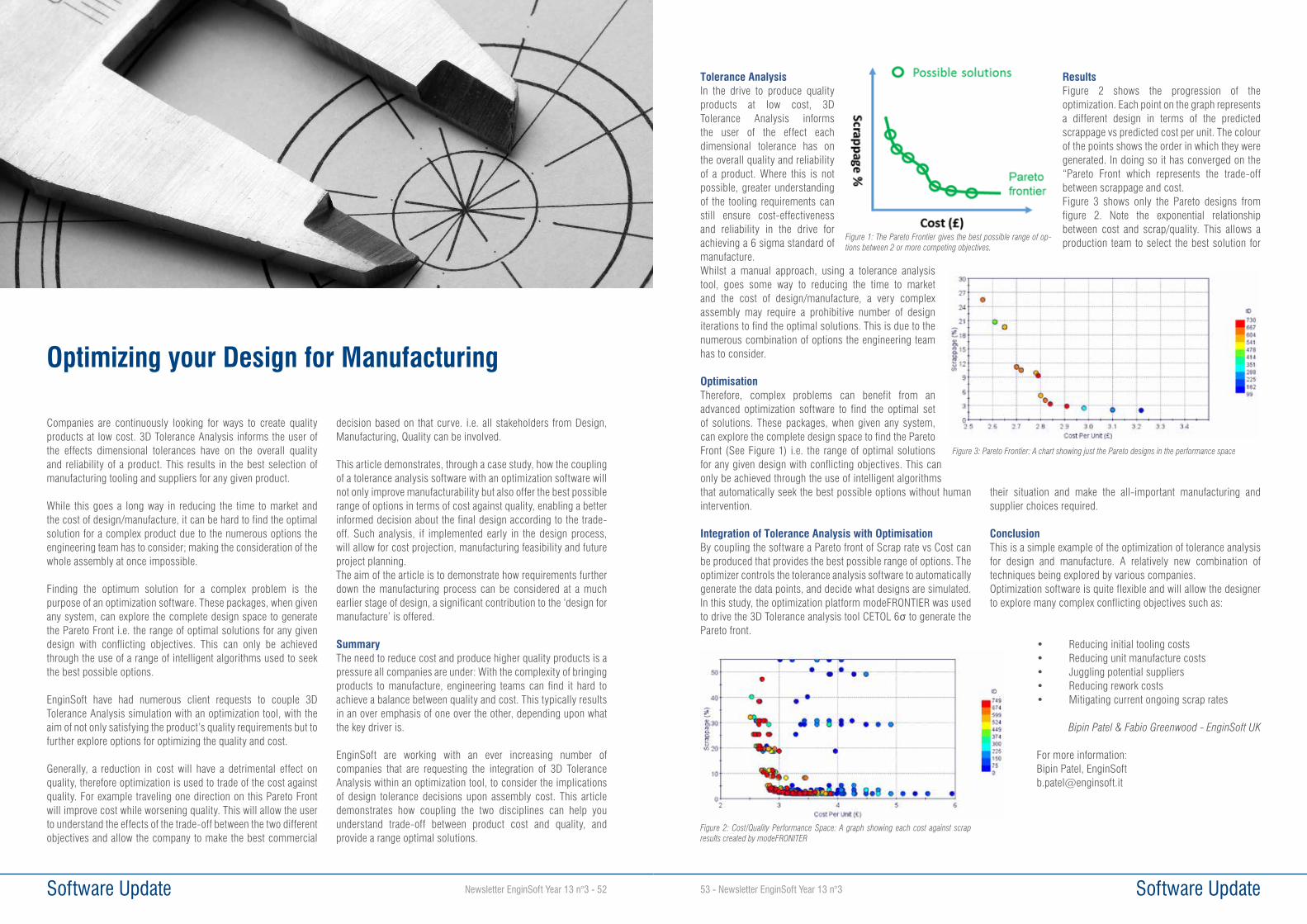
Newsletter EnginSoft Year 13 n°3 - 52 Software Update53 - Newsletter EnginSoft Year 13 n°3 Software Update
Companies are continuously looking for ways to create quality products at low cost. 3D Tolerance Analysis informs the user of the effects dimensional tolerances have on the overall quality and reliability of a product. This results in the best selection of manufacturing tooling and suppliers for any given product.
While this goes a long way in reducing the time to market and the cost of design/manufacture, it can be hard to find the optimal solution for a complex product due to the numerous options the engineering team has to consider; making the consideration of the whole assembly at once impossible.
Finding the optimum solution for a complex problem is the purpose of an optimization software. These packages, when given any system, can explore the complete design space to generate the Pareto Front i.e. the range of optimal solutions for any given design with conflicting objectives. This can only be achieved through the use of a range of intelligent algorithms used to seek the best possible options.
EnginSoft have had numerous client requests to couple 3D Tolerance Analysis simulation with an optimization tool, with the aim of not only satisfying the product’s quality requirements but to further explore options for optimizing the quality and cost.
Generally, a reduction in cost will have a detrimental effect on quality, therefore optimization is used to trade of the cost against quality. For example traveling one direction on this Pareto Front will improve cost while worsening quality. This will allow the user to understand the effects of the trade-off between the two different objectives and allow the company to make the best commercial
decision based on that curve. i.e. all stakeholders from Design, Manufacturing, Quality can be involved.
This article demonstrates, through a case study, how the coupling of a tolerance analysis software with an optimization software will not only improve manufacturability but also offer the best possible range of options in terms of cost against quality, enabling a better informed decision about the final design according to the trade-off. Such analysis, if implemented early in the design process, will allow for cost projection, manufacturing feasibility and future project planning. The aim of the article is to demonstrate how requirements further down the manufacturing process can be considered at a much earlier stage of design, a significant contribution to the ‘design for manufacture’ is offered.
SummaryThe need to reduce cost and produce higher quality products is a pressure all companies are under: With the complexity of bringing products to manufacture, engineering teams can find it hard to achieve a balance between quality and cost. This typically results in an over emphasis of one over the other, depending upon what the key driver is.
EnginSoft are working with an ever increasing number of companies that are requesting the integration of 3D Tolerance Analysis within an optimization tool, to consider the implications of design tolerance decisions upon assembly cost. This article demonstrates how coupling the two disciplines can help you understand trade-off between product cost and quality, and provide a range optimal solutions.
Optimizing your Design for Manufacturing
Tolerance AnalysisIn the drive to produce quality products at low cost, 3D Tolerance Analysis informs the user of the effect each dimensional tolerance has on the overall quality and reliability of a product. Where this is not possible, greater understanding of the tooling requirements can still ensure cost-effectiveness and reliability in the drive for achieving a 6 sigma standard of manufacture. Whilst a manual approach, using a tolerance analysis tool, goes some way to reducing the time to market and the cost of design/manufacture, a very complex assembly may require a prohibitive number of design iterations to find the optimal solutions. This is due to the numerous combination of options the engineering team has to consider.
OptimisationTherefore, complex problems can benefit from an advanced optimization software to find the optimal set of solutions. These packages, when given any system, can explore the complete design space to find the Pareto Front (See Figure 1) i.e. the range of optimal solutions for any given design with conflicting objectives. This can only be achieved through the use of intelligent algorithms that automatically seek the best possible options without human intervention.
Integration of Tolerance Analysis with OptimisationBy coupling the software a Pareto front of Scrap rate vs Cost can be produced that provides the best possible range of options. The optimizer controls the tolerance analysis software to automatically generate the data points, and decide what designs are simulated.In this study, the optimization platform modeFRONTIER was used to drive the 3D Tolerance analysis tool CETOL 6σ to generate the Pareto front.
ResultsFigure 2 shows the progression of the optimization. Each point on the graph represents a different design in terms of the predicted scrappage vs predicted cost per unit. The colour of the points shows the order in which they were generated. In doing so it has converged on the “Pareto Front which represents the trade-off between scrappage and cost. Figure 3 shows only the Pareto designs from figure 2. Note the exponential relationship between cost and scrap/quality. This allows a production team to select the best solution for
their situation and make the all-important manufacturing and supplier choices required.
ConclusionThis is a simple example of the optimization of tolerance analysis for design and manufacture. A relatively new combination of techniques being explored by various companies.Optimization software is quite flexible and will allow the designer to explore many complex conflicting objectives such as:
• Reducing initial tooling costs• Reducing unit manufacture costs• Juggling potential suppliers• Reducing rework costs• Mitigating current ongoing scrap rates
Bipin Patel & Fabio Greenwood - EnginSoft UK
For more information: Bipin Patel, [email protected]
Figure 1: The Pareto Frontier gives the best possible range of op-tions between 2 or more competing objectives.
Figure 2: Cost/Quality Performance Space: A graph showing each cost against scrap results created by modeFRONITER
Figure 3: Pareto Frontier: A chart showing just the Pareto designs in the performance space

Software Update55 - Newsletter EnginSoft Year 13 n°3 Software Update Newsletter EnginSoft Year 13 n°3 - 54
For over 20 years EnginSoft has been operating with a group of engineers dealing with the simulation of production processes. Our activity ranges from the daily assistance to over 200 Italian customers of MagmaSoft of Magma GmbH, Forge and Thercast of Transvalor SA and training of companies undertaking the path to simulation, to sale activities and development of ad-hoc moduli. We support companies to obtain the best possible value from simulation, measuring the related benefits. Some experiences are presented here highlighting the obtained returns and the improvement of the process/product quality.
Hot forging of steel and non-ferrous metalsThe hot closed die forging of steel products has been the first process investigated with CAE, considering the repetitiveness of these parts. The focus is mainly on the quality of the workpiece, which must be complete and without folds, but also on the die-life of the dies under strong thermo-mechanical cycles.EnginSoft has supported FEAT Group in the development of an optimized routine of the forging process in three stations of a steel yoke. Objectives: To reduce the material used and to preserve the dies, subject to premature failure. Thanks to an automatic optimization routine present in Forge®, the size and location of the billet have been changed and some geometrical details of the die have been adjusted. The result has been a 27 % reduction of the material volume in the flash and a 24% reduction of the tonnage required during preforming, thus doubling the useful die-life previously subject to failure. Hot forging of non-ferrous materials (brass and copper, aluminum, titanium alloys, …) considers more complex details in shape, with
particular processes, with or without flash. ZMF, a company specialized in brass, aluminum, bronze and copper forging, has integrated the use of Forge in the design for about ten years. The main benefits have been a correspondence of simulation
with respect to reality next to 98% and an historical archive of forging experience, useful to reduce the decision-making time in case of requests for similar products, as well as to train new professionals in just few months. In the following example EnginSoft has supported ZMF in the selection of the ideal shape of the billet in brass CW617N to guarantee the correct filling of the dies cavity, solving the fold problem in the lateral connection and affecting the quality of the original component with a 20% saving of the material.As far as aluminum forging is concerned, EnginSoft has recently supported an important company in the review of the forging sequence of an automotive component. The performed analysis has solved a
Practical examples of processes/products improvements thanks to simulation
fold problem, reduced the stock allowances and led to a totally new distribution of the material fibres, with highly improved mechanical performance in those areas more subject to operating load.We have also an ongoing project which involves a press manifacturer and a brass forging plant, where EnginSoft is calculating the whole dynamic of the press with ANSYS/MBDA, transferring to Forge the correct action on the lower cushion related to the punches movement, undergoing the material stress during deformation. Going back to steel, in a reduced configuration, it has been a very important experience to work with Officine Ambrogio Melesi, performing the analysis of a Venturi convergent component for Oil & Gas in Inconel 800H alloy, which is new one for the company. Forge has been used to experiment both a new start and an operation reversal, which have led not only to the total elimination of the instability problems detected on the punch, but also to a >50% reduction of stock allowances thus reducing the machining costs. The component belongs to a family of parts and the adoption of this approach has led to immediate cost-savings and a return on the investment.
Open die forging - forging and heat treatment In the open die forging, ingots of several tons of steel are deformed (the figure shows an ingot of over 500tons) and a special attention is paid to the so-called “forging receipt”, considering the stoke sequence and the intermediate re-heatings, to guarantee the requested reduction factor, shape with minimum stock allowances and a heart porosity closure as a consequence of the casting. Almost all the forged parts are then thermally treated so to improve the mechanical properties. The simulation of this operation requires not only a correct assessment of the grain size during forging operations,
but also the prediction of the metallurgical phases evolution, in order to predict the distribution of the hardness and of the residual stresses.Forgiatura Moderna Arese has chosen Forge and EnginSoft to better understand and improve its own internal processes, starting from the technical-commercial proposition. Here below the sequence to obtain an hollow cylindrical section forging from a 10 tons ingot of steel P355. The simulation of the next normalization process (AUST+AIR COOL), in accordance with the EN10250-2 standard, showed a non-compliance in the failure stress in the control points. Forge has been therefore used to assess a hardening and tempering process (AUST+QUENCH+TEMP), which reported values in the range of the required specifications. The order was acquired and it has been possible to start the production avoiding expensive tests. We have also
worked for an important Italian iron metallurgy company, simulating a cogging process, with 17 stokes on a stainless steel ingot, which was physically validated with a minor deviation of <2% between real and simulated results. The new sequence of cogging has led to a 18% reduction in the process total time, balancing the press operations with a control on the internal damage. The tracking of the riser area has furthermore allowed to optimize the final cutting position, saving a 15% of the material.

Software Update57 - Newsletter EnginSoft Year 13 n°3 Software Update Newsletter EnginSoft Year 13 n°3 - 56
Continuous casting & ingots castingThe distribution of the porosity, as a result of the casting operations of ingots and continuous casting, is an extremely important topic to be taken into account when forging, stamping or rolling. Thercast is the tool we use to simulate the processes of ingots casting and continuous casting: the modelling of filling and solidification allows to identify shape and location of porosity and such information are directly transferred to the forging, stamping or rolling operation.
Ring rolling rings and rolling of long productsThe secret of the rolling process of rings, either rectangular or shaped, is the design of the lamination curves in order to obtain the requested shape thus controlling stability.FELB has used FORGE to transform the way of producing a shaped ring (900mm diameter), previously obtained by rolling and deep machining. Thanks to the support of EnginSoft, integrating the company know-how, it has been possible to verify the process feasibility in less than one week, selecting the necessary equipment. The forging process of the preformed has been set up in just few days, while waiting for the last tools, and the production has started with only minimal adjustments.
Luigi Catalini, CEO of FELB, told us that the production, according to the traditional approach for a not shaped part, would not have been competitive for such a large number of pieces (over 200). Thanks to simulation, the setting up time has been reduced of 4-5 times, while
machining costs have decreased of 40% thanks to minimum stock allowances (-15% weight) and with a different fibers distribution that allows to reach even higher superficial hardness than the one required by FELB. The importance of simulation can be perceived not only from the added value obtained by the company but also in the estimation according to which, FELB will return on the software and hardware investment done with EnginSoft and for the person working on it with just 4-5 parts more to be treated like this one.
The rolling of long productsIn the rolling of long products, the cage calibration is simulated in terms of material deformation, also considering forces, torques and rollers wear, without carrying out experimental tests. This is the experience of the AFV Beltrame Group, that has been supported by EnginSoft in the development of an ad-hoc calculation procedure, starting from the design of the 2D roll profiles, up to the validation of the rolling train. This approach is fundamental in the lamination of the profiles which are not symmetrical (see figure). FORGE was also used to design the cutting process of the rolled section, in order to reduce distortions and eliminate the head/tail waste.
Cold FormingCAE tools are widely used also in multi-station cold forming, due to the reduced tolerances required to pieces and to the high loads affecting the cavities and the punches.Vimi Fasteners has integrated Forge in the production system in less than 6 months, reducing the time-to-market of 40% and eliminating the re-design phase of the equipment after sampling. Thanks to simulation, folds and not complete fillings have been predicted and avoided for standard steels, while induction heating processes and
non-conventional alloys thermal treatments have been modeled so to evaluate fibres evolution, microstructure and hardness.Also Ceratizit, reference company in the production of hard metal inserts, required EnginSoft support to create an internal FEM competence centre, so to assist customers’ requests and to provide inserts with maximum life and performance, able to withstand the most extreme load conditions.
Simulation of the melting processIn case of ferrous and non-ferrous metals foundry processes, it is possible to analyze filling, solidification and thermal treatments to obtain the mechanical and microstructural properties, as well as the deformations and residual stresses in the components and the moulds. In this context EnginSoft uses and supports companies using MagmaSoft.
Fonderia Tecnopress experienced a not acceptable quality level in an aluminum automotive diecasting component after the first sampling. EnginSoft has changed the injection curve and the casting geometry and implemented with the company a virtual optimization for over 300 configurations; the best one has reduced defects due to air entrapment of 90%, limiting them to non-critical areas. The achieved results have marked the route for similar components, with relevant scale economies for the company.
Fonderia GFT has simulated with EnginSoft the gravity casting process of a single-arm fork made of Al alloy for a Triumph Speedtriple, “naked” motorcycle where this piece is visible and therefore has to be aesthetically perfect while ensuring the maximum performance.This study has considered the analysis of the mould thermal regime, by identifying the optimal mix of geometric parameters and process. Samplings have been avoided and the production trend has improved up to a 30%, which is useful to meet the delivery requested by the customer.
With Fonderia di Torbole, EnginSoft has simulated the core-making process of a core for a ventilated brake disc in cast iron using MAGMA software C+M. Objective: To reduce the power required by the process. After the calibration on the real process, three assumptions have been assessed: modification of the insulation, application of electric heaters and oil heating thermo-regulated system. The energy cost to produce 800,000 pcs/year was more than 20,000 €/year and it has been reduced by 38%, 60% and 85% for the three presented solutions, therefore reaching a tangible energy efficiency.
ConclusionsIn all these examples, it is evident how the FEM simulation process is the only tool able to guarantee, in a very limited time, a dramatic improvement of the quality and the cost-effectiveness of the process/product. A company, willing to undergoing this path without an expert guide, may often incur in disappointing situations, negatively affecting the introduction of these tools in the company and the daily routine management with their several advantages.EnginSoft approach is characterized by the great attention paid to the developments of the technologies we distribute, keeping a continuous contact with the developers, as well as looking for new technologies able to meet our customers’ expectations.
Thanks to this approach, we have recently integrated tools for the tolerance chain calculation (CETOL 6s) and interfaced general-purpose or open-source calculation tools to generate the boundary conditions necessary for the correct definition of the problems. Likewise we pay great attention to the development of new tools, such as more and more accurate database
of materials (JMatPro) or software to calculate the microstructure evolution at a crystal grain level (DIGIMU), an indispensable element to introduce the non-uniform behavior, which is present in real pieces.We invite you to share with us your cases of interest, so to look together for the most appropriate approach, to validate it with your processes and, if effective, to rely on us for a correct and rapid implementation in your company procedures.
Marcello Gabrielli, Federico Fracasso, Giampietro ScarpaEnginSoft
For more information: Marcello Gabrielli - EnginSoft - [email protected]
Article published on La Metallurgia Italiana, n. 7/8 Luglio Agosto 2016, pagg. 27-32 Anno 108 ISSN 0026-0843

Newsletter EnginSoft Year 13 n°3 - 58 Software Update
Introduction to RecurDyn’s ContactsRecurDyn offers the largest and richest portfolio of features for contact modelling in the panorama of commercial multibody simulation software.
The contact library (Table 1) features more than 30 different contact types, which cover any possible need. 2D contacts are provided to model the interaction between 2D profiles, such as line bodies and edges. 3D contacts are provided to describe the interaction between solid bodies and surfaces. Each group is further split into analytical (also called primitive) contacts and general ones (Figure 1).Contact elements in multibody are conceived to generate a repulsive force between any couple of geometrical entities that overlap. This simple sentence hides two complex mathematical problems. First, the contacting condition has to be detected by measuring degree,
extension and speed of geometric overlapping. Second, a force, opportunely oriented in space, has to be generated in accordance to both contact kinematics and contact properties.Analytical contacts use spheres, cylinders, cones, arcs, tori, and boxes, to perform the contact detection. All of these primitives are described by relatively simple equations and a few sizing parameters. Therefore, the detection task is completed with superior accuracy and very high numerical efficiency. General contacts use surface (or line) meshes to approximate the actual geometries and detect the overlapping kinematics between bodies. The more refined the mesh, the better the approximation, but, at
Recurdyn’s Premium Contact Technology
Table 1 – Main classification of RecurDyn’s contact features
Figure 1 – Examples of different contact feature types available in RecurDyn
Software Update59 - Newsletter EnginSoft Year 13 n°3
the same time, the higher the number of unknowns introduced with the contact.General contacts always make the calculation time much longer. The user should resort to general contacts only when actual interacting geometries cannot be replaced by one or more of the available analytical primitives. Since RecurDyn has the largest library of analytical contacts available on the market, a large number of real situations can be efficiently approximated. For the remaining cases, where general contacts are unavoidable, RecurDyn’s advanced algorithms deliver excellent performances (with respect to competitors) and unparalleled accuracy.
Contact Force FormulationEvery time the elements of a contact feature overlap, then RecurDyn generates a contact force, which has both normal and tangential (friction) components (Figure 2). By tuning the many contact parameters, it is possible to finely and conveniently govern the way such force grows as function of the contact kinematics (penetration, penetration rate and tangential speed).
The normal force is obtained as sum of “stiffness component” and “damping component”. The stiffness component Fk describes the relationship between bodies penetration δ and contact force, through a non-linear equation featuring two parameters: the stiffness k and the exponent of the penetration m1. The Fk stiffness force versus the penetration δ is plotted in Figure 3. The curve shape clearly depends on the m1 coefficient: for m1=1 the
stiffness force is proportional to the penetration, while for m1>1 or m1<1 the curves become respectively the blue or the green one. The stiffness force is always positive, which means that it is a repulsive force.The damping component of the normal force is a nonlinear function of both penetration rate and penetration value. The equation features three parameters: the damping coefficient c, the damping exponent m2 and the indentation exponent m3. The damping force is oriented as the penetration rate and, therefore, it might change in sign. The m2 exponent changes the shape of the force versus speed curve. The indentation exponent m3 has been added to the equation to allow different damping as the body penetration change. The Figure 4 shows how the damping force Fc depends on both exponents.
The normal force is always perpendicular to the contacting surface and is applied at the contact point. The friction force is a nonlinear function of the sliding velocity between the contacting geometries (Figure 2). For relative speed equal to or higher than the dynamic threshold value, the friction force is proportional to the normal force through the dynamic friction coefficient. For relative speed equal to the static threshold velocity the friction force is proportional to the normal force through the static friction coefficient. Since at null relative speed there is no friction, the simulation of quasi static friction states requires to set very small values of the static threshold velocity. The friction force is always parallel to the contacting surface, applied at the contact point, with opposite direction with respect to the relative speed.
Figure 2 – RecurDyn’s contact formulation: normal force and friction force laws
Figure 3 – Influence of m1 (stiffness exponent) over the Fk stiffness component of the Fn contact normal force
Figure 4 - Influence of m2 (damping exponent) and m3 (indentation exponent) over the Fc damping component of the Fn contact normal force
Figure 5 – Bounding Box definition and an example of calculated Bounding Boxes

Software Update Newsletter EnginSoft Year 13 n°3 - 60
The described contact force model is very versatile. By tuning the coefficients it is possible to reproduce any type of contact response, including hysteretic cycles with high mechanical energy dissipation.
Boosting General ContactsRecurDyn’s contact technology includes some tricks that, once combined with the solver capabilities, deliver excellent performances even in presence of large meshed contacts.For instance, contact nodes (or, more correctly, nodes which are candidates to become contact points) are smartly organized in 3D domains and sub-domains for fast searching of mutual penetration. For any contact element, both “base” and “action” bodies are enclosed into a Bounding Box. The bounding box is simply the enveloping box scaled by a parameter called Bounding Buffer Length (Figure 6).
As long as there is no overlap between base Bounding Box and action Bounding Box, then the contact is identified as open contact and no check is performed on the candidate nodes contained inside. If the bounding boxes overlap, then the contact is identified as upcoming contact and the contact search algorithm is activated (Figure 6). Each bounding box is divided into further sub-boxes (not shown), to provide a faster identification of the nodes which cross the elements lying on the other side of the contact. Furtherly, the Maximum Stepsize Factor is a useful parameter of RecurDyn contacts that forces a smaller stepsize only in upcoming contact state (allowing a faster integration when contacts are not activated).
Geo Surface Contact TechnologyAs said above, general contacts use a meshed representation of contacting surfaces to get the kinematic quantities to generate the contact forces. The discretization of the geometrical entities necessarily transforms a continuous problem into a discontinuous one. This has at least two negative impacts on the contact management. First, the facetted representation of bodies and surfaces is always inaccurate in presence of curvature. The error can be reduced by refining the mesh, but this increases the model size. Second, the discontinuity causes noise on the contact outputs. These are known issues in the area of computational dynamics, especially when dealing with multi-flexible-body dynamics (MFBD). Indeed, flexible bodies are always represented through
Finite Elements and the surface mesh is necessarily adopted also to define contacts. Contact noise and inaccuracy can be very important in the simulation of precise mechanisms problems such as gear contacts or cam-valve contacts. These problems have been overcome in RecurDyn through an enhanced contact feature called “Geo Surface Contact”. The Geo Contact algorithm fits the contact meshes (triangular or quadrilateral) on both base and action bodies with a cubic spline surface. As a result, the mesh is used as support grid to recreate a continuous mathematical formulation of the contact.The restored continuity impressively improves the computational efficiency. This is really evident for models featuring a large number of contacts and a large number of nodes per contact. However, the Geo Contact algorithm is not just an advanced fitting technology.First, it performs a two phases searching of the contact nodes (pre-search and detailed-search), leading to an appreciable time saving. Then, it calculates the contact force using the local curvature and the Hertzian theory. The Geo Surface Contact can model contact interactions involving both rigid and flexible bodies, solid and surfaces, with practical no limits. The method has been proved to be robust, accurate and numerically efficient. Contact outputs are smooth and detailed.
Geo Surface Contact BenefitsThis chapter provides a significant example where the Geo Contact Algorithm really makes the difference. The test model is a valve train including rotating cam, valve (i.e. the follower) and spring. The device is firstly simulated considering all rigid bodies (Figure 7), with and without Geo-Surface option.
Table 2 gives an overview of the main simulation parameters, whereas Table 3 lists the parameters of the contact, which has been set between the cam and the valve.Figure 8 shows the contact force magnitude returned by the rigid model without (blue line) and with Geo-Contact algorithm (dotted red line). The technology strongly reduces the output noise and, at the same time, the CPU time passes from t = 2.49s to t = 2.16s (-13%). This enhancement is achieved thanks to a more accurate and smooth contact force and Jacobian calculation.The same mechanism is finally simulated considering a flexible valve body (Figure 9). The valve mesh consists of 6900 nodes
Figure 7 – Multibody model 1, featuring rigid cam – rigid valve contact interaction
Figure 6 – Results of the contact detection algorithm execution in an example multibody simulation (track system): upcoming contacts are included in contact calculations while open contacts are ignored
Software Update61 - Newsletter EnginSoft Year 13 n°3
and 9700 linear solid elements (hexahedrons). Once again, the simulation is repeated with and without Geo-Surface option.Benefits of the Geo-Contact algorithm are really highlighted in Figure 10. The noise in the output force almost disappears and the calculation time passes from t = 367.5s to t = 263.0s (-28%).
For more information:Fabiano Maggio, [email protected]
Figure 8 – Contact force magnitude in model 1 (rigid cam – rigid valve). The solid blue line is the non-smooth case while the dotted red line is the smooth case
Figure 9 – Multibody model 2, featuring rigid cam – flexible valve contact interaction
Figure 10 – Contact force magnitude in model 2 (rigid cam – flexible valve). The solid blue line is the non-smooth case while the dotted red line is the smooth case
Table 2 – Simulation parameters of the cam – valve example models
Table 3 – Contact parameters of the cam – valve example models
EnginSoft’s System Dynamics TeamFrom a simulation point of view, dynamics is really a particular discipline. Indeed, the understanding of time-variable phenomena on multi-part systems, requires cross competences in mechanics, structures, controls, hydraulics, pneumatics, tires, electrical devices. The user has to understand the physics of the system to be simulated and convert it into a combination of software features. A unique standard approach does not exist: the modeling phase really decides the level of accuracy, the simulation time, and the reliability of the outputs.EnginSoft has always put great resources to keep a high level of competence in this field. The knowledge gained in many years of activity is today organized within the System Dynamics Team, based in Padova. The team delivers engineering consulting, software support, customized training and is active in several collaborations with universities. Besides
using RecurDyn for true Multi-Flexible-Body-Dynamics (MFBD), the team also exploits ANSYS to provide advanced solutions to those problems involving both structural and global dynamics. modeFRONTIER is normally used as well, for model calibration purposes and to optimize the dynamical response of the analyzed systems. Both signal processing capabilities and analytical modeling skills complete the pedigree of this team of multi-body passionate people.
Engineering services have been delivered in automotive, agricultural equipment, industrial equipment, robotics, automation, and textile industry sectors. The number of customers is growing as the importance of dynamics in the design of moving systems becomes evident. The supported simulating software RecurDyn has been appreciated by many new customers for its simplicity and effectiveness, opening interesting scenarios for the close future.
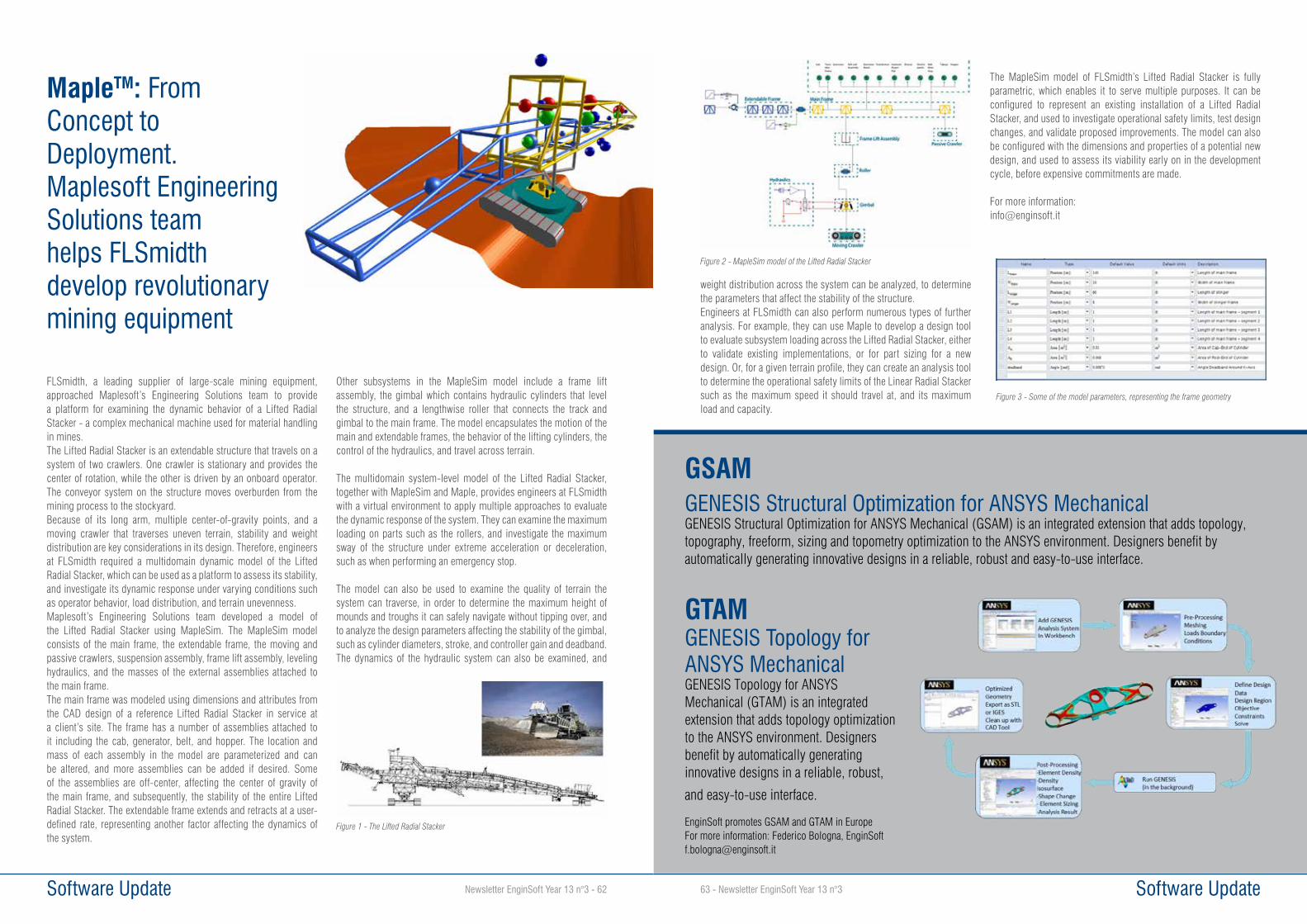
Newsletter EnginSoft Year 13 n°3 - 62 Software Update
FLSmidth, a leading supplier of large-scale mining equipment, approached Maplesoft’s Engineering Solutions team to provide a platform for examining the dynamic behavior of a Lifted Radial Stacker - a complex mechanical machine used for material handling in mines.The Lifted Radial Stacker is an extendable structure that travels on a system of two crawlers. One crawler is stationary and provides the center of rotation, while the other is driven by an onboard operator. The conveyor system on the structure moves overburden from the mining process to the stockyard.Because of its long arm, multiple center-of-gravity points, and a moving crawler that traverses uneven terrain, stability and weight distribution are key considerations in its design. Therefore, engineers at FLSmidth required a multidomain dynamic model of the Lifted Radial Stacker, which can be used as a platform to assess its stability, and investigate its dynamic response under varying conditions such as operator behavior, load distribution, and terrain unevenness.Maplesoft’s Engineering Solutions team developed a model of the Lifted Radial Stacker using MapleSim. The MapleSim model consists of the main frame, the extendable frame, the moving and passive crawlers, suspension assembly, frame lift assembly, leveling hydraulics, and the masses of the external assemblies attached to the main frame.The main frame was modeled using dimensions and attributes from the CAD design of a reference Lifted Radial Stacker in service at a client’s site. The frame has a number of assemblies attached to it including the cab, generator, belt, and hopper. The location and mass of each assembly in the model are parameterized and can be altered, and more assemblies can be added if desired. Some of the assemblies are off-center, affecting the center of gravity of the main frame, and subsequently, the stability of the entire Lifted Radial Stacker. The extendable frame extends and retracts at a user-defined rate, representing another factor affecting the dynamics of the system.
Other subsystems in the MapleSim model include a frame lift assembly, the gimbal which contains hydraulic cylinders that level the structure, and a lengthwise roller that connects the track and gimbal to the main frame. The model encapsulates the motion of the main and extendable frames, the behavior of the lifting cylinders, the control of the hydraulics, and travel across terrain.
The multidomain system-level model of the Lifted Radial Stacker, together with MapleSim and Maple, provides engineers at FLSmidth with a virtual environment to apply multiple approaches to evaluate the dynamic response of the system. They can examine the maximumloading on parts such as the rollers, and investigate the maximum sway of the structure under extreme acceleration or deceleration, such as when performing an emergency stop.
The model can also be used to examine the quality of terrain the system can traverse, in order to determine the maximum height of mounds and troughs it can safely navigate without tipping over, and to analyze the design parameters affecting the stability of the gimbal, such as cylinder diameters, stroke, and controller gain and deadband. The dynamics of the hydraulic system can also be examined, and
MapleTM: From Concept to Deployment.Maplesoft Engineering Solutions teamhelps FLSmidth develop revolutionarymining equipment
Figure 1 - The Lifted Radial Stacker
Software Update63 - Newsletter EnginSoft Year 13 n°3
weight distribution across the system can be analyzed, to determine the parameters that affect the stability of the structure.Engineers at FLSmidth can also perform numerous types of further analysis. For example, they can use Maple to develop a design tool to evaluate subsystem loading across the Lifted Radial Stacker, either to validate existing implementations, or for part sizing for a new design. Or, for a given terrain profile, they can create an analysis tool to determine the operational safety limits of the Linear Radial Stacker such as the maximum speed it should travel at, and its maximum load and capacity.
The MapleSim model of FLSmidth’s Lifted Radial Stacker is fully parametric, which enables it to serve multiple purposes. It can be configured to represent an existing installation of a Lifted Radial Stacker, and used to investigate operational safety limits, test design changes, and validate proposed improvements. The model can also be configured with the dimensions and properties of a potential new design, and used to assess its viability early on in the development cycle, before expensive commitments are made.
For more information:[email protected]
Figure 2 - MapleSim model of the Lifted Radial Stacker
Figure 3 - Some of the model parameters, representing the frame geometry
GSAM GENESIS Structural Optimization for ANSYS MechanicalGENESIS Structural Optimization for ANSYS Mechanical (GSAM) is an integrated extension that adds topology, topography, freeform, sizing and topometry optimization to the ANSYS environment. Designers benefit by automatically generating innovative designs in a reliable, robust and easy-to-use interface.
GTAMGENESIS Topology for ANSYS MechanicalGENESIS Topology for ANSYS Mechanical (GTAM) is an integrated extension that adds topology optimization to the ANSYS environment. Designers benefit by automatically generating innovative designs in a reliable, robust,
and easy-to-use interface.
EnginSoft promotes GSAM and GTAM in EuropeFor more information: Federico Bologna, EnginSoft [email protected]

Newsletter EnginSoft Year 13 n°3 - 64 Hardware Update
In the scenario of commercial software for CFD, structural mechanical and electromagnetic calculation, customers are increasingly looking for the correct assessment of the price/performance ratio between software and hardware.Furthermore, the well-consolidated trend over the last 10 years, with reference to processors speed, is that of giving priority to the number of parallel processes instead of pure calculation speed. This is mainly due to the problems of energy efficiency and dissipation of the components of the processor itself. It is therefore necessary to carefully evaluate the hardware characteristics, in relation to the available software licenses, so to ensure the greatest speed possible in the analysis resolution.
The characteristics that have to be taken into account are: • The number of available cores with respect to the number of
available parallel licenses• The actual speed of the processor• The type of the available computer: Server/Workstation
It is very important to consider the correct acquisition of the calculation tool in relation to the kind of work to be performed.Normally, for small-medium mechanical-structural calculations (<4M equations), desktop workstations are more efficient, since they are much more manageable and with a limited cost. One of the most important feature of a calculation workstation is the full availability of the system only for the running analysis, avoiding promiscuity with normal back-office work carried out simultaneously.In the scenario of current systems, a series of tests has been carried out comparing the calculation times on a series of typical systems for small & medium enterprises, having license availability for 8 parallels maximum.
The characteristics of the systems are: a calculation server with Intel® Xeon® Processor and5-2670 2.60 GHz (20 core) - 128GB RAM - only 8 used for the simulation Standard Workstation with Intel® Core™ i7-5820K Processor 3.60 GHz (6 core) - 64Gb RAM BOXX Workstation with Intel® Core™ i7-5960X Processor 3.50 GHz (8 core) - 64GB RAM. In particular BOXX Technologies (www.boxx.com), an American company specialized in very high performance systems and represented in Europe by E4 Computer Engineering, provides guaranteed support so to have very high performance systems that cannot be obtained with the current availability of the market. The tests carried out are the following ones: the analysis of the same model made of 500 million nodes has been run on each workstation and calculation server, using up to 8 cores (or 6 in the case of Standard Workstation), then collecting the calculation times. It follows that: with an availability of 6-8 HPC licenses, the Workstation BOXX with an high performance processor due to data processing high speed takes less with a lower hardware investment in comparison with a calculation server. Final consideration: for license configurations between 6 and 8 parallels, it is more important to correctly select the right configuration of the hardware rather than a high number of cores that remain unused. BOOX workstations proved to be advantageous in terms of costs/benefits ratio.
For more information:Andrea Pancrazzi, EnginSoft - [email protected]
How to choose the optimized hardware for HPC
Figure 1 - Workstation BOXX
Figure 2 - Benchmark Results
EnginSoft IT technicians are always looking for a hardware able to maximize the potentialities of the software technologies available on the market, in order to increase simulation speed and performances
Events65 - Newsletter EnginSoft Year 13 n°3
Coverciano (Fiesole - Florence, June 22nd, 2016)
A full day of technical and managerial meetings in the name
of simulation
The “Aula Magna” of the Football Technical Center of Coverciano , on the hills of Fiesole , hosted two important meeting last June 22nd, with the common theme of simulation, but articulated in different meetings, according to specific topics.The morning activities were dedicated to technical analyses concerning the ANSYS code, while the afternoon sessions were devoted to understand the new an complex requirements of companies, oriented to the use of simulation also in relation to the new IOT (Internet of Things) perspective.The first meeting, on its 10th edition, has followed the traditional structure, gathering the Italian ANSYS users with ANSYS technical staff, so to discuss the current development of the code (ANSYS 17.1), analyzing both the technical objectives already achieved (code capabilities) and the next development stages in accordance with the daily requests coming from different engineering disciplines. This year’s edition has been characterized by the presence of both structural and fluid-dynamic engineers. In the past the two groups were requiring the development of different capabilities for the software; now their needs are becoming the same ones: analysis
execution times, results accuracy, attention for specifications and regulations, as well as multidisciplinary of innovation.The forthcoming scenario is characterized by a small group of mechanical and fluid-dynamic master experts in niche sectors and a big group of users dealing with CFD and FEM analyses, thus not allowing a simplification for the different fields of application.Generally speaking the software response is related to the development of the three main sectors, which are: fracture mechanics enhancement for FEM; combustion for CFD; efficient parallel solver for both technologies plus easy and intuitive meshing using AIM (ANSYS Integrates Multi-physics).
The debate among the different companies and the strong commitment of ANSYS to meet its customers’ needs have been highly appreciated.In this perspective, it’s worth underlining the great daily effort which is profused to overcome the current criticalities and to face the future simulation scenarios. The customers’ feedback have been very positive but have also pointed out need requests to be taken into account for specific single engineering applications.
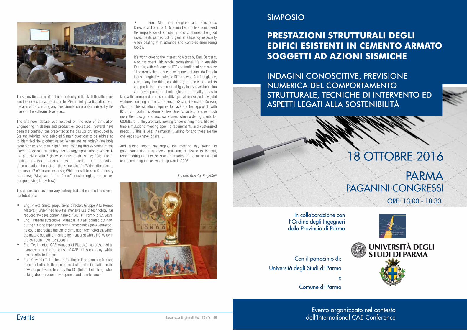
Events Newsletter EnginSoft Year 13 n°3 - 66
These few lines also offer the opportunity to thank all the attendees and to express the appreciation for Pierre Tieffry participation, with the aim of transmitting any new simulation problem raised by the users to the software developers.
The afternoon debate was focused on the role of Simulation Engineering in design and productive processes. Several have been the contributions presented at the discussion, introduced by Stefano Odorizzi, who selected 5 main questions to be addressed to identified the product value: Where are we today? (available technologies and their capabilities; training and expertise of the users, processes suitability; technology application); Which is the perceived value? (How to measure the value; ROI; time to market; prototype reduction; costs reduction, error reduction, documentation; impact on the value chain); Which direction to be pursued? (Offer and request); Which possible value? (industry priorities); What about the future? (technologies, processes, competencies, know-how).
The discussion has been very participated and enriched by several contributions:
• Eng. Pivetti (moto-propulsions director, Gruppo Alfa Romeo Maserati) underlined how the intensive use of technology has reduced the development time of “Giulia”, from 5 to 3.5 years.
• Eng. Franzoni (Executive Manager in A&D)pointed out how, during his long experience with Finmeccanica (now Leonardo), he could appreciate the use of simulation technologies, which are mature but still difficult to be measured with a ROI value in the company revenue account.
• Eng. Testi (actual CAE Manager of Piaggio) has presented an overview concerning the use of CAE in his company, which has a dedicated office .
• Eng. Giovani (IT director at GE office in Florence) has focused his contribution to the role of the IT staff, also in relation to the new perspectives offered by the IOT (Internet of Thing) when talking about product development and maintenance.
• Eng. Marmorini (Engines and Electronics Director at Formula 1 Scuderia Ferrari) has considered the importance of simulation and confirmed the great investments carried out to gain in efficiency especially when dealing with advance and complex engineering topics.
It’s worth quoting the interesting words by Eng. Barberis, who has spent his whole professional life In Ansaldo Energia, with reference to IOT and traditional companies: “Apparently the product development of Ansaldo Energia is just marginally related to IOT process. At a first glance, a company like this , considering its reference markets and products, doesn’t need a highly innovative simulation and development methodologies, but in reality it has to
face with a more and more competitive global market and new joint ventures dealing in the same sector (Shangai Electric, Doosan, Alstom). This situation requires to have another approach with IOT. Its important customers, like Oman’s sultan, require much more than design and success stories, when ordering plants for 600MEuro … they are really looking for something more, like real-time simulations meeting specific requirements and customized needs … This is what the market is asking for and these are the challenges we have to face …
And talking about challenges, the meeting day found its great conclusion in a special museum, dedicated to football, remembering the successes and memories of the Italian national team, including the last word cup won in 2006.
Roberto Gonella, EnginSoft
SIMPOSIO
PRESTAZIONI STRUTTURALI DEGLI EDIFICI ESISTENTI IN CEMENTO ARMATO SOGGETTI AD AZIONI SISMICHE
INDAGINI CONOSCITIVE, PREVISIONE NUMERICA DEL COMPORTAMENTO STRUTTURALE, TECNICHE DI INTERVENTO ED ASPETTI LEGATI ALLA SOSTENIBILITÀ
18 OTTOBRE 2016
PARMAPAGANINI CONGRESSI
ORE: 13:00 - 18:30
Evento organizzato nel contesto dell’International CAE Conference
Con il patrocinio di:
Università degli Studi di Parma
e
Comune di Parma
In collaborazione conl’Ordine degli Ingegneridella Provincia di Parma

TAVOLA ROTONDA
AGGREGAZIONE TRA IMPRESE, CENTRI DI RICERCA ED UNIVERSITÀ
MODELLI, OPPORTUNITÀ E BEST PRACTICE
18 OTTOBRE 2016
PARMAPAGANINI CONGRESSI
Evento organizzato nel contesto dell’International CAE Conference
ORE: 8:45 - 13:00