Simulation and Structural Analysis of Modules During Land Transportation
7
CONCEPTUALIZATION, SIMULATION AND STRUCTURAL ANALYSIS OF MODULES DURING LAND TRANSPORTATION BY SELF PROPELLED MODULAR TRANSPORTATION (SPMT) Rahul P. JANI 1 , Mrudul A. THAKAR 2 ABSTRACT : In major modular construction projects, predominant in construction sites which experience severe weather conditions, heavy modules built in the fabrication yard are transported on road either to Project site or to designated Lay Down Areas using multi wheeled transporters commonly known as Self Propelled Modular Transportation (SPMT) or Rubber Tire Vehicle (RTV).Considering SPMT in motion, which builds up static and dynamic forces in to the system due to wind, braking, undulation and slopes on roads, the behavior of the structure becomes unpredictable and difficult to analyze. Module behavior on SPMT in motion has to be conceptualized using simplistic approach and simulated in structural analysis software to analyze the module. The objective of analysis is to control the excessive deflection of SPMTs (normally stipulated by the manufacturer) and to check the module strength and serviceability limits under the enforced equilibrium system. The author, by taking study of a Project executed in Russia, has laid down the guidelines for behavioral simulation and static analysis of modules during Road transportation using third party software (RISA 3d). 1 INTRODUCTION In modularization of plants or refineries, heavy and large fabricated completed modules need to be transported on land to site in stages using SPMT (Self Propelled Modular Transportation) or RTVs (Rubber Tire vehicles). A typical SPMT has a rigid longitudinal girder supported by a train of rubber tire axles, which have a specific load carrying capacity. The typical SPMT train is assembled with sections of 6 axles and/or 4 axles per sections. Typical axle spacing in the longitudinal direction is 1.4 meters. Each axle holds 4 rubber tires. The girders are connected to the tires by hydraulic jacks and springs. The hydraulic jacks have the same hydraulic pressure and the same load carrying capacity. Hence, the SPMT through the reaction from the tires provide a uniform distributed load at the bottom irrespective of the line of action of downward load. SPMTs are powered by power packs attached on one or either ends. The number of tire axles, associated length and number of trains required are determined by the logistic group, based on the factors like weight, stiffness and length of modules as well as permissible bearing strength of roadway and maximum permissible rubber tire pressure. Typical for modules which are tall and heavy, module weight is somewhat concentrated, requiring SPMT lengths to be longer than that of the module so as to distribute the load uniformly and keeping within permissible tire load. The typical view of module land transportation is shown in Figure 1. 2 ANALYSIS CONCEPTUALIZATION The primary purpose of the land transportation analysis is to analyze the equilibrium condition of the structure under the combination of loads from the structure and the reaction from the wheels. The induced stresses are likely to be different in nature than that of the normal on-site conditions. 1 Associate Design Engineer II, Fluor Daniel India Pvt. Ltd., India 2 Associate Design Engineer II, Fluor Daniel India Pvt. Ltd., India 1
Transcript of Simulation and Structural Analysis of Modules During Land Transportation
CONCEPTUALIZATION, SIMULATION AND STRUCTURAL ANALYSIS OF MODULES
DURING LAND TRANSPORTATION BY SELF PROPELLED MODULAR
TRANSPORTATION (SPMT)
Rahul P. JANI 1, Mrudul A. THAKAR 2
ABSTRACT : In major modular construction projects, predominant in construction sites which
experience severe weather conditions, heavy modules built in the fabrication yard are transported on
road either to Project site or to designated Lay Down Areas using multi wheeled transporters
commonly known as Self Propelled Modular Transportation (SPMT) or Rubber Tire Vehicle
(RTV).Considering SPMT in motion, which builds up static and dynamic forces in to the system due
to wind, braking, undulation and slopes on roads, the behavior of the structure becomes unpredictable
and difficult to analyze. Module behavior on SPMT in motion has to be conceptualized using
simplistic approach and simulated in structural analysis software to analyze the module. The objective
of analysis is to control the excessive deflection of SPMTs (normally stipulated by the manufacturer)
and to check the module strength and serviceability limits under the enforced equilibrium system. The
author, by taking study of a Project executed in Russia, has laid down the guidelines for behavioral
simulation and static analysis of modules during Road transportation using third party software (RISA
3d).
1 INTRODUCTION
In modularization of plants or refineries, heavy and large fabricated completed modules need to be
transported on land to site in stages using SPMT (Self Propelled Modular Transportation) or RTVs
(Rubber Tire vehicles). A typical SPMT has a rigid longitudinal girder supported by a train of rubber
tire axles, which have a specific load carrying capacity. The typical SPMT train is assembled with
sections of 6 axles and/or 4 axles per sections. Typical axle spacing in the longitudinal direction is 1.4
meters. Each axle holds 4 rubber tires. The girders are connected to the tires by hydraulic jacks and
springs. The hydraulic jacks have the same hydraulic pressure and the same load carrying capacity.
Hence, the SPMT through the reaction from the tires provide a uniform distributed load at the bottom
irrespective of the line of action of downward load. SPMTs are powered by power packs attached on
one or either ends.
The number of tire axles, associated length and number of trains required are determined by the
logistic group, based on the factors like weight, stiffness and length of modules as well as permissible
bearing strength of roadway and maximum permissible rubber tire pressure. Typical for modules
which are tall and heavy, module weight is somewhat concentrated, requiring SPMT lengths to be
longer than that of the module so as to distribute the load uniformly and keeping within permissible
tire load. The typical view of module land transportation is shown in Figure 1.
2 ANALYSIS CONCEPTUALIZATION
The primary purpose of the land transportation analysis is to analyze the equilibrium condition of the
structure under the combination of loads from the structure and the reaction from the wheels. The
induced stresses are likely to be different in nature than that of the normal on-site conditions.
1 Associate Design Engineer II, Fluor Daniel India Pvt. Ltd., India2 Associate Design Engineer II, Fluor Daniel India Pvt. Ltd., India
1

Sometimes, it is required to additionally stiffen the structure (example: Addition of horizontal
diaphragms, vertical bracings) corresponding to this behavior. The other side of the analysis is to
determine the deflection of the SPMT girder. Most of the suppliers of SPMT do have an allowable
vertical deflection specified for the longitudinal girder. It will be structural engineer’s responsibility to
keep the vertical deflection within that limit.
Module on SPMT exhibits equilibrium system when the module Center of Gravity coincides with the
corresponding centerline of the SPMT system, as illustrated in Figure 1. Empty module weight and
self weight of SPMTs with power packs acting in downward direction constitutes “ACTION” in the
system. Equal and opposite “REACTION” is generated through wheel pressure on SPMT, which
maintains the whole system in equilibrium. This normally creates a different supporting system for the
modules inducing dissimilar sag and hog forces as compared to normal “on-site” conditions. Also,
since the lengths of application of action and reaction are different, especially in cases where a longer
SPMT length than that of the module is required to reduce tire pressure, the system causes the SPMT
to deflect in a dish shape. The module has a tendency to bridge over the dish and be supported at the
two ends. This in turn induces heavy force in to the structure depending upon the stiffness and
geometry of the module. The paper outlines the design philosophy and guidelines adopted for static
simulation of the module transportation.
Figure 1. Module Equilibrium System
3 ANALYTICAL SIMULATION
The precise estimation of stresses induced in the structure and the SPMT girder deflection can be
achieved by analytical simulation of the exact behavior of the module during land transportation in
third party software by imposing the conditions of equilibrium system of the module and the SPMT
system. Typically in a process module, the loading is not symmetrical nor the geometry which
necessitates the requirement of 3D structural analysis to determine the impact of the module
transportation.
3.1 MODELING
The analytical model developed to analyze “on-site” condition of the module is used and further
developed for this analysis. The boundary conditions defined for the column bases for the onsite
analysis shall be removed. The SPMT longitudinal girder is modeled based on the sectional properties
furnished by the supplier. For a typical process module, the points of contact between the SPMT and
the module are at locations at the bottom of transverse girders. To leave room for vertical adjustment,
shim or spacer beams are provided below the girders to transfer the load. Since the module girders and
SPMT girders are modeled at their respective center lines, the connection between the two is done by
introducing rigid links with specific boundary conditions as shown in Figure 2 to depict the truss
behavior of the members. These elements should always be in compression.
Power pack
Modulemounted
on SPMT
SPMT
Module weightC.G.(Action)
Wheel pressure CG(Reaction)
L/2
a b
L/2
2
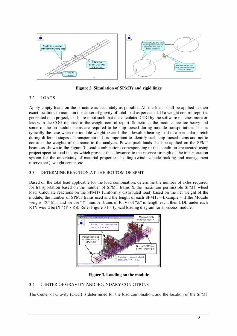
Figure 2. Simulation of SPMTs and rigid links
3.2 LOADS
Apply empty loads on the structure as accurately as possible. All the loads shall be applied at their
exact locations to maintain the center of gravity of total load as per actual. If a weight control report is
generated on a project, loads are input such that the calculated COG by the software matches more or
less with the COG reported in the weight control report. Sometimes the modules are too heavy and
some of the on-module items are required to be ship-loosed during module transportation. This is
typically the case when the module weight exceeds the allowable bearing load of a particular stretch
during different stages of transportation. It is important to identify such ship-loosed items and not to
consider the weights of the same in the analysis. Power pack loads shall be applied on the SPMT
beams as shown in the Figure 3. Load combinations corresponding to this condition are created using
project specific load factors which provide the allowance to the reserve strength of the transportation
system for the uncertainty of material properties, loading (wind, vehicle braking and management
reserve etc.), weight center, etc.
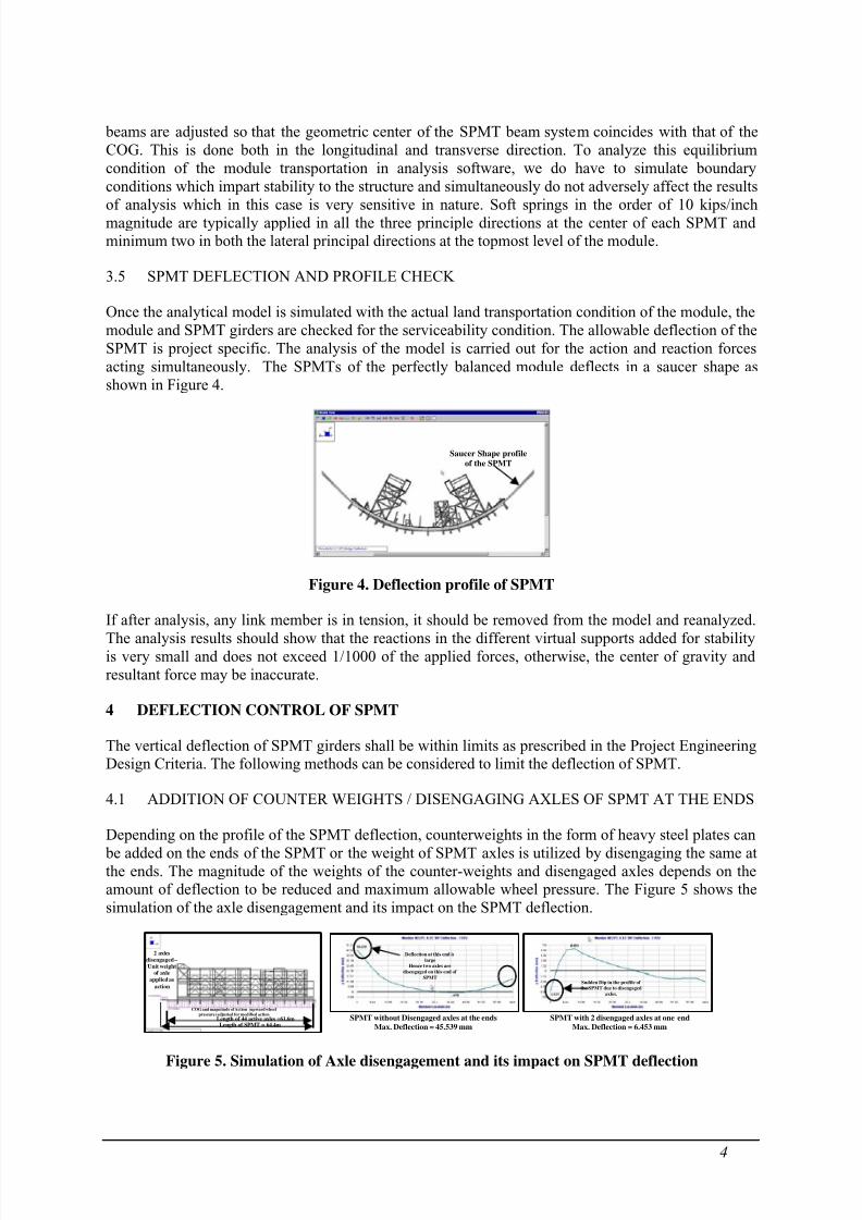
3.3 DETERMINE REACTION AT THE BOTTOM OF SPMT
Based on the total load applicable for the load combination, determine the number of axles required
for transportation based on the number of SPMT trains & the maximum permissible SPMT wheel
load. Calculate reactions on the SPMTs (uniformly distributed load) based on the net weight of the
module, the number of SPMT trains used and the length of each SPMT. – Example – If the Module
weighs “X” MT, and we use “Y” number trains of RTVs of “Z” m length each, then UDL under each
RTV would be (X / (Y x Z)). Refer Figure 3 for typical loading diagram for a process module.
Act ion : All Downw ard
loads, X = X1 + X2
Reaction: Upward wheel
pressure,R=X / (Y x Z)
PowerPack loadat either ends of
SPMT, X2
Module Empty
condition load, X1
Nos. of SPMTs=Y
SPMT length=Z m
Figure 3. Loading on the module
3.4 CENTER OF GRAVITY AND BOUNDARY CONDITIONS
The Center of Gravity (COG) is determined for the load combination, and the location of the SPMT
3
beams are adjusted so that the geometric center of the SPMT beam system coincides with that of the
COG. This is done both in the longitudinal and transverse direction. To analyze this equilibrium
condition of the module transportation in analysis software, we do have to simulate boundary
conditions which impart stability to the structure and simultaneously do not adversely affect the results
of analysis which in this case is very sensitive in nature. Soft springs in the order of 10 kips/inch
magnitude are typically applied in all the three principle directions at the center of each SPMT and
minimum two in both the lateral principal directions at the topmost level of the module.
3.5 SPMT DEFLECTION AND PROFILE CHECK
Once the analytical model is simulated with the actual land transportation condition of the module, the
module and SPMT girders are checked for the serviceability condition. The allowable deflection of the
SPMT is project specific. The analysis of the model is carried out for the action and reaction forces
acting simultaneously. The SPMTs of the perfectly balanced module deflects in a saucer shape as
shown in Figure 4.
Saucer Shape profile
of the SPMT
Figure 4. Deflection profile of SPMT
If after analysis, any link member is in tension, it should be removed from the model and reanalyzed.
The analysis results should show that the reactions in the different virtual supports added for stability
is very small and does not exceed 1/1000 of the applied forces, otherwise, the center of gravity and
resultant force may be inaccurate.
4 DEFLECTION CONTROL OF SPMT
The vertical deflection of SPMT girders shall be within limits as prescribed in the Project Engineering
Design Criteria. The following methods can be considered to limit the deflection of SPMT.
4.1 ADDITION OF COUNTER WEIGHTS / DISENGAGING AXLES OF SPMT AT THE ENDS
Depending on the profile of the SPMT deflection, counterweights in the form of heavy steel plates can
be added on the ends of the SPMT or the weight of SPMT axles is utilized by disengaging the same at
the ends. The magnitude of the weights of the counter-weights and disengaged axles depends on the
amount of deflection to be reduced and maximum allowable wheel pressure. The Figure 5 shows the
simulation of the axle disengagement and its impact on the SPMT deflection.
Length of SPMT = 64.4mLength of 44 active axles =61.6m
2 axles
disengaged –
Unit weightof axle
applied as
action
COG and magnitude of Action (upward wheel
pressure) adjusted for modified action
Deflection at this end is
large
Hence two axles are
disengaged on this end of
SPMTSudden Dip in the profile of
the SPMT due to disengaged
axles.
SPMT without Disengaged axles at the ends
Max. Deflection = 45.539 mm
SPMT with 2 disengaged axles at one end
Max. Deflection = 6.453 mm
Figure 5. Simulation of Axle disengagement and its impact on SPMT deflection
4

4.2 STIFFENING OF THE MODULE BY OUTRIGGERS
This is very effective method in controlling the large deflections of the SPMTs having larger
cantilever lengths & heavier modules. The module is stiffened by introducing temporary steel frame
projecting outside the module called as outriggers on one or either ends such that the line of action of
forces due to deflection of SPMT is continuous from one end of the module to the other as shown in
Figure 6. The outrigger frame connections with the module are bolted connections so that outriggers
can be removed easily and reused for other similar modules.
Outriggers
LER
Main
Module
Isometric View showing Outriggers
Outrigger Frames on both the ends
protruding outside the module
Main Module
Longitudinal End Frame of the module
Module length
Outrigger
ProjectionOutrigger
Projection
-Bolted Connection of
outrigger with module
- Approx. Load path through
compressive stresses
Figure 6. Stiffening of the Module by Outriggers
Figure 7 shows the control of SPMT deflection using outriggers. Maximum deflection of SPMT is
978mm for the module without outriggers. After outrigger addition at the ends of the module,
deflection is reduced from 978 mm to 737mm as shown in Figure 7.
Base frame with a temporary trussMax. Deflection = 737 mm
Local Equipment
Room (LER)
Main Module
Outrigger protruding outs
ide
the module
Original module without stiffening
Max. Deflection = 978 mm
Local Equipment
Room (LER)
Main Module
Main module and LER are fabricated on
the single base frame.
Figure 7. Deflection control of SPMT by Outriggers
5 MODIFICATIONS REQUIRED TO SATISFY THE STRENGTH REQUIREMENT OF
MODULE MEMBERS
Once the deflection of the SPMTs is below the permissible limits, the next important task is to check
the strength requirement of the module and carry out necessary modifications to satisfy the same.
Some of the important aspects are mentioned below:
• The transverse girders of the base frame are subjected to heavy shear forces at the point of
contact with the shim beams. It is mandatory to stiffen the web of the girders to take these
heavy shear forces as shown in the Figure 8
Stiffeners at SPMT
locations to strengthen the
girder web
Power packs
of SPMT
Shim beams
to distribute
the load
C/L of SPMTs
Heavy Shear force in
Girder at SPMT
location
Vertical Shear force diagram of Transverse Girder
Figure 8. Stiffening of Girder web for heavy shear forces
5
• Sometimes, depending on the load flow path, moment at the base of the module column is
very high due to SPMT deflection. To redistribute the heavy forces in the column, one might
consider the introduction of a vertical stay connecting base frame longitudinal girder and the
concerned column. This brace attracts majority of the force from the column and distributes
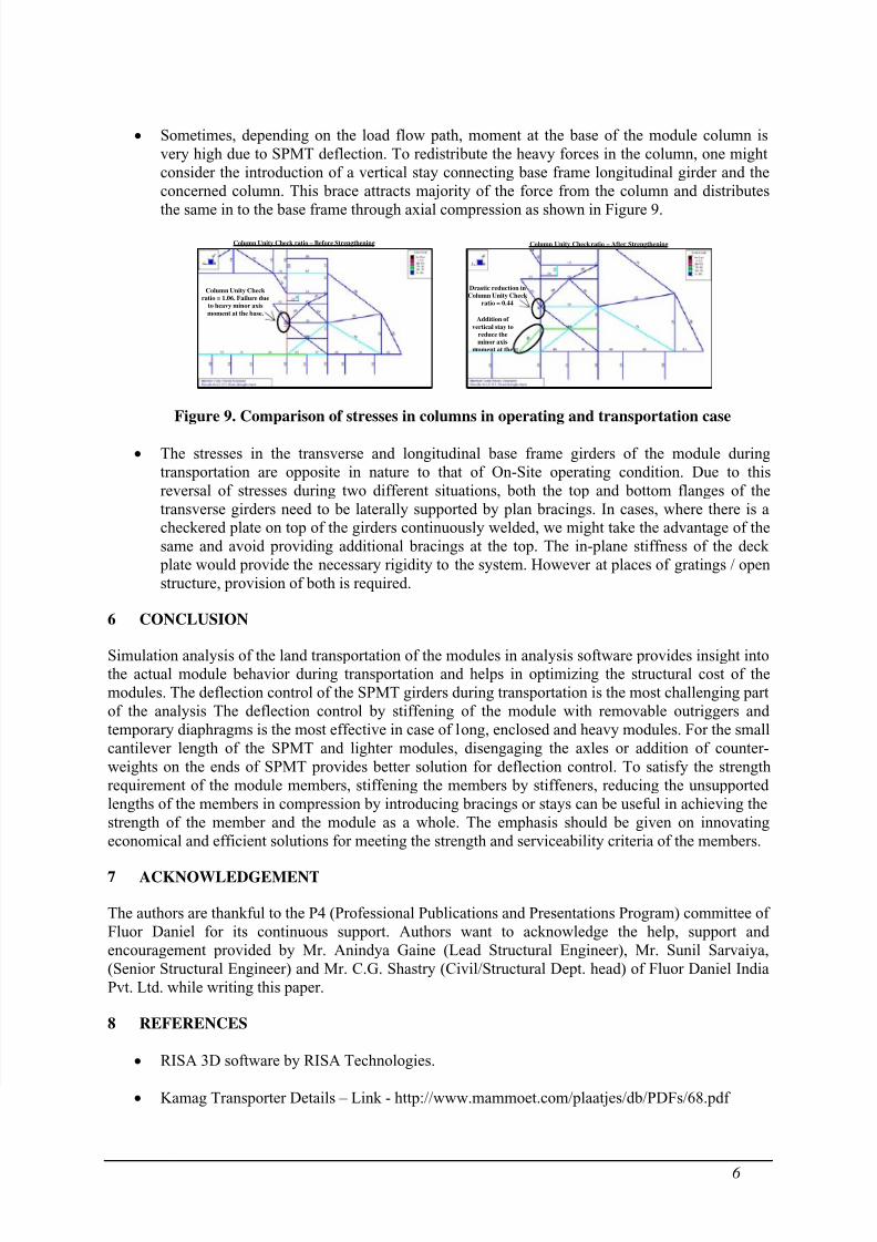
the same in to the base frame through axial compression as shown in Figure 9.
Column Unity Check ratio – Before Strengthening Column Unity Check ratio – After Strengthening
Column Unity Check
ratio = 1.06. Failure due
to heavy minor axis
moment at the base.
Drastic reduction in
Column Unity Check
ratio = 0.44
Addition of
vertical stay to
reduce the
minor axis
moment at the
Figure 9. Comparison of stresses in columns in operating and transportation case
• The stresses in the transverse and longitudinal base frame girders of the module during
transportation are opposite in nature to that of On-Site operating condition. Due to this
reversal of stresses during two different situations, both the top and bottom flanges of the
transverse girders need to be laterally supported by plan bracings. In cases, where there is a
checkered plate on top of the girders continuously welded, we might take the advantage of the
same and avoid providing additional bracings at the top. The in-plane stiffness of the deck
plate would provide the necessary rigidity to the system. However at places of gratings / open
structure, provision of both is required.
6 CONCLUSION
Simulation analysis of the land transportation of the modules in analysis software provides insight into
the actual module behavior during transportation and helps in optimizing the structural cost of the
modules. The deflection control of the SPMT girders during transportation is the most challenging part
of the analysis The deflection control by stiffening of the module with removable outriggers and
temporary diaphragms is the most effective in case of long, enclosed and heavy modules. For the small
cantilever length of the SPMT and lighter modules, disengaging the axles or addition of counter-
weights on the ends of SPMT provides better solution for deflection control. To satisfy the strength
requirement of the module members, stiffening the members by stiffeners, reducing the unsupported
lengths of the members in compression by introducing bracings or stays can be useful in achieving the
strength of the member and the module as a whole. The emphasis should be given on innovating
economical and efficient solutions for meeting the strength and serviceability criteria of the members.
7 ACKNOWLEDGEMENT
The authors are thankful to the P4 (Professional Publications and Presentations Program) committee of
Fluor Daniel for its continuous support. Authors want to acknowledge the help, support and
encouragement provided by Mr. Anindya Gaine (Lead Structural Engineer), Mr. Sunil Sarvaiya,
(Senior Structural Engineer) and Mr. C.G. Shastry (Civil/Structural Dept. head) of Fluor Daniel India
Pvt. Ltd. while writing this paper.
8 REFERENCES
• RISA 3D software by RISA Technologies.
• Kamag Transporter Details – Link - http://www.mammoet.com/plaatjes/db/PDFs/68.pdf
6