Simple Peel Tensile Tester with Visual Inspection...
34
PTT-100V Simple Peel Tensile Tester with Visual Inspection Unit Printed SEP 2009 1st Edition 1.01E Operating Instuructions ® van der stähl scientific, inc.
Transcript of Simple Peel Tensile Tester with Visual Inspection...

PTT-100VSimple Peel Tensile Tester with Visual Inspection Unit
Printed SEP 20091st Edition 1.01E
Operating Instuructions
®van der stählscientific, inc.

PTT-100V Operating Instructions Ver1.01E

This manual is designed to cover machines of various voltages and plug configurations
About the warning labels
Foreword
The warning labels indicate when there is a danger of injury to the operator or damage to the ma-chine.
Below is a list of what each label denotes.
Caution Minor injuries or damages to the unit may occur when the instruction is ignored.
Warning Critical injuries or fatal accidents will almost certainly occur when the instruction is ignored.
Danger Critical injuries or fatal accidents will almost certainly occur when the instruction is ignored.
Attention! Important Notes and Restrictions - Read the directions in order to avoid misuse of the unit.
TIPS Great Tips and References when using the unit - Highly recommend reading through the information.
Before using, always verify the voltage specification of your particular unit and operate it at the correct voltage.
Please note the following:
1) The voltage specification of your unit is listed on the label which displays the serial number. This label can be found on the machine body.
2) The explanations and illustrations in this operators' manual utilize the following standard plug configurations most common in Japan. However, due to the various configurations in use worldwide, these may not necessarily correspond with the one attached to your specific unit.
100V15A以下
200V20A
100V20A
200V30A
100V20A、30AWarning Voltages and plug configurations differ according to various worldwide specifications.
Always verify those of your particular unit before beginning operation. Connecting the power cord to an outlet of a different specification is extremely hazardous.
Thank you for purchasing the Fuji Impulse PTT-100V. Please read all of the safety and operating instructions before operating this machine. Periodic maintenance and proper operation are necessary to ensure safety when using PTT-100V.Keep this manual on hand when operating the sealer. As a result of research to further improve the PTT-100V, some details in the operating instructions may differ from your actual machine. For operating problems or product information, please contact your local dealer or Fuji Impulse.
PTT-100V Operating Instructions Ver1.01E
3

Table of contents1 Specification ………………………………………………………………………………………… 5
2 Package Contents …………………………………………………………………………………… 6
3 Operating Precautions ……………………………………………………………………………… 7
4 Major parts and function …………………………………………………………………………… 8
5 Machine Installation ………………………………………………………………………………… 9
6 Preparation ………………………………………………………………………………………… 106-1 Set the Thin-Film Grips …………………………………………………………………………………………………………… 10
6-2 Insert the Lens ……………………………………………………………………………………………………………………… 10
6-3 Connect to the Power Source……………………………………………………………………………………………………… 11
6-4 Turn ON the Power Switch ………………………………………………………………………………………………………… 11
7 Initial Setting of the Machine …………………………………………………………………… 127-1 Registering the Administrator and Operator ID ………………………………………………………………………………… 12
7-2 <MENU 8> Setting the Date ……………………………………………………………………………………………………… 15
7-3 <MENU 9> Setting the Time ……………………………………………………………………………………………………… 15
7-4 <MENU 10> Adjusting the Time …………………………………………………………………………………………………… 16
7-5 <MENU 11> Delete the On-Board Memory ……………………………………………………………………………………… 16
8 Set the Measuring Condition …………………………………………………………………… 178-1 <MENU 2> Chuck Distance ……………………………………………………………………………………………………… 18
8-2 <MENU 3> Unit Select……………………………………………………………………………………………………………… 18
8-3 <MENU 4> Peel Mode……………………………………………………………………………………………………………… 18
8-4 <MENU 5> Peel Speed …………………………………………………………………………………………………………… 18
8-5 <MENU 6> Seal Lines ……………………………………………………………………………………………………………… 19
8-6 <MENU 7> Inspection ……………………………………………………………………………………………………………… 19
9 Proper Use of the Machine and Measuring Method ………………………………………… 209-1 Operation Pattern 1 - Without the Administrator ID - …………………………………………………………………………… 20
9-1-1 Perform the visual inspection with VIU …………………………………………………………………………………… 20
9-1-2 Perform the peel tensile testing with PTT ………………………………………………………………………………… 22
9-2 Operation Pattern 2 - With the Administrator ID - ……………………………………………………………………………… 27
9-2-1 Perform the visual inspection with VIU …………………………………………………………………………………… 27
9-2-2 Perform the peel tensile test with PTT …………………………………………………………………………………… 27
10 Transferring Data to the PC ……………………………………………………………………… 28
11 About Calibration ………………………………………………………………………………… 28
12 Replacing the Routine Maintenance Parts …………………………………………………… 2912-1 Replacing the battery ……………………………………………………………………………………………………………… 29
12-2 Replacing the Fuse ………………………………………………………………………………………………………………… 30
13 Adjusting the VIU Photosensor ………………………………………………………………… 31
14 Electric Diagram …………………………………………………………………………………… 32
15 Error Fix Solutions ………………………………………………………………………………… 33
PTT-100V Operating Instructions Ver1.01E
4

Maximum peel strangth 100N
Units N, Kgf, Lbf
Sampling 100 point/sec
Increments 0.1N
Computer data interface USB
Operating temperature range +5 - 40 degrees C/ 41 to 104 degrees F
Operating humidity range 30 - 80%RH
PowerAC100V-AC240V 50/60Hz (Optional power cord required to the voltages greater than AC125V)
Power consumption 9W
Machine dimension W370 x D310 x H200 mm
Machine weight About 10Kg
LED white LED 3pcs.
Sensor Photo sensor to detect the film
1 Specification
Peel Tensile Tester -PTT-
Visual Inspection Unit -VIU-
PTT-100V Operating Instructions Ver1.01E
5

Please make sure that all of the accessories described below are included.If not, please contact your dealer.
2 Package Contents
Other accessories
These illustrations are not reduced equally.
Thin-film grip ... 1 pc. Grip fixing pin ... 1 pc.
Film cutting template ... 1 pc.
Specimen setting gauge ... 1 pc.
PTT-100V Operating Instructions Ver1.01E
6
Name Amount
Power cord 7A-125V (2m) 1
USB cable (1.5m) 1
Operating instructions 1
Inspection certificate 1
Protection cover 1
Operate the machine as described in the following safeguards. Fuji Impulse shall not be responsible for any damages results from the misuse of the machine against this operating direction.
3 Operating Precautions
Warning
・ This machine consists of the high performance sensor and electric circuit that is applied by the distortion gauge. Avoid rapid temperature change, high humidity, water, dusts, and strong shock.
・ This machine is tensile load measuring equipment. Do not use the machine other than measuring tensile load.
・ The operating temperature range for this machine is from 5 to 40 degrees C (41 to 104 F). For accuracy, it is ideal that the machine is used in the temperature described in the certificate of inspection.
・ Regardless of the power being ON or OFF, do not twist or apply force exceeding rated capacity to the sensor measurement axis.
・ When tensile testing the material that might break or whose fragment may scatter, please operate the machine after making sure to protect yourself from getting injured.
・ Do not disassemble or modify the machine.
・ Remove the thin-film grip on the measurement-side when not using the machine in order to prevent the damage to the measuring axis.
PTT-100V Operating Instructions Ver1.01E
7

4 Major parts and function
Control Unit Panel
Arrow keyUsed to move the cursor or change the displayed content at the menu mode.
Power lampTurns ON when the power is ON.
VIU lampTurns ON while using the VIU unit.
PTT lampTurns ON while testing with the PTT.
ERROR lampTurns ON when the abnormality occurs.
INSPECT buttonPress when inspecting with VIU and PTT units.
PASS/FAIL buttonUsed for inputting VIU pass or fail.
PEEL START/ STOP button
Used to start or stop the peel tensile testing.
MENU buttonSwitch the menu mode displayed on the screen.
ENTER keyConfirms the set condition.
Numeric keyUsed to input numerical values.
Display
VIU unit Sensor part
Grip part
Inspects the sealing surface.
The load-cell for measuring the load. (Compression load cell)
Power switchA switch for turning ON and OFF the power.( I : ON, ○ : OFF)
Control PanelUsed for operating the machine or changing the setting.
Clamp and fix the test piece.
Displays the measured results and set conditions etc.
USB port
PTT-100V Operating Instructions Ver1.01E
8

Surrounding temperature and humidity
Place the machine on a flat place
Do not set the machine to the following places:
Please use the machine in the following work environment.
Place the machine on a flat, horizontal working table. Placing the machine on an unstable place may affect the precision of the test result due to the instability.
・ Exposed to the direct rays of the sun or the heat source.・ Exposed to continuous vibration caused by machines.・ Close to the noise generator such as high voltage products and power source.・ Exposed to the strong electromagnetic pluses.・ With rapid temperature change, high humidity, the dust, and surrounded by the corrosiveness gas.・ Unstable to place the machine.
<Others>・ For more accurate measuring, operate the machine in the temperature described in the certificate of
inspection.・ When installing the machine to the place where humidity is less than 30%, please use products such as
an anti-static mat to prevent static electricity.・ Condensation occurs when the machine is exposed to the rapid temperature change. If the condensation
occurs, leave the machine in the new environment more than one hour before using. Use the machine after confirmed that there is no condensation.
5 Machine Installation
PTT-100V Operating Instructions Ver1.01E
9
Temperature 5 - 40 degrees C
Humidity 20 - 80%RH

The thin-film grip on the measurement side is not attached at the time of factory shipment. Insert a pin to fix the grip as in the following directions.
1 Set the thin-film grip on the measurement side to the sensor axis as in the illustration on the right.
2 Insert a fixing Pin when the hole of the chuck and sensor axis overlap.
1 Insert the lens to the body.
6 Preparation6-1 Set the Thin-Film Grips
6-2 Insert the Lens
Grip fixing pin
Measurement sensor axis
Thin-film grip on the measurement side
VIU lens
Insert the lens so the longer side of the cutout comes right when facing toward the machine.
Caution Remove the thin-film grip on the measurement side when not using the machine for a while or at the time of the shipment.
Caution Do not apply force exceeding rated capacity to the measuring axis. The sensor may be damaged.
Attention! Make sure that the lens is facing the proper direction. Otherwise, it may not insert.
Caution VIU lens is made of plastic lens. Do not drop or scratch it.
PTT-100V Operating Instructions Ver1.01E
10

Turn ON the power switch to “ ” position. The display will show the software version such as “VO.01” and the date and time few seconds later.
When the Administrator and Operator IDs are registered and activated, the display will show the passward input menu before the date/time display. Input the Administrator or Operator password of the person who are going to use the machine.
If the inputted password is registered, the display will show the corresponding ID. Put any button to display date/time. For the detail of ID registration, please refer to “7 Initial Setting of the Machine.”
1 Make sure that the machine power switch is in OFF position.
2 Connect the plug of the power cord, included in the accessories, to the connector located on the rear panel of the machine.
3 Insert the other end of the electrical power plug into the watt outlet that has adequate current carrying capacity as described in “1 Specification.”
6-3 Connect to the Power Source
6-4 Turn ON the Power Switch
e.g.) 3-pole electrical outlet
PTT-100V Operating Instructions Ver1.01E
11

Please set perform the initial setting of the machine with the following directions.
PTT-100V can register the Administrator ID and Operator IDs. Inspection can be performed without registering the IDs. In that case, however, please note that the inspection modes and other setting can be changed by anyone. Also the output data to the PC will be “OPERATOR” as the operator name.
When only the Administrator ID is registeredWhen only the Administrator ID is registered, the inspection modes and other settings can be changed only by those who know the Administrator password. The output data to the PC will be “ADMINIST” as the operator name.
When both the Administrator and Operator IDs are registeredWhen both of the Administrator and Operator IDs are registered, the inspection modes and other settings can be changed only when the Administrator is logged in. Operators cannot change the operation settings. When the error message is shown on the display, only the Administrator can resolve the problem. The output operator name to the PC will be the Operator name activated during the operation.
When the Operator IDs are registered without activating the Administrator IDWhen only the Operator IDs are registered, each setting menu can be changed by those who knows the Operator passwords. The output operator name to the PC will be the Operator name activated during the operation.
Press the MENU and key so that MENU 1 indicated above is shown on the display.
Press the ENTER key. The display will show the following.
The setting is activated. Note that inputting “0” will deactivate the setting. If you would like to continue setting an Administrator password, go to the next process without pressing the ENTER key.
Press ENTER key when not changing the password from “000000.”
Activate/ deactivate the Administrator IDPress key to place the cursor on the position indicated below so that it flashes.
Input “1” using the numeric key.
7 Initial Setting of the Machine
7-1 Registering the Administrator and Operator ID
<MENU 1> Setting the Administrator ID
00 : 0 : <ADMINIST><000000>
00 : 1 : <ADMINIST><000000>
00 : 0 : <ADMINIST><000000>
MENU 1OPERATOR SETTINGMENU ENTER
Administrator IDAdministrator ID is fixed to “ADMINIST” and cannot be changed.
PasswordThe six-digit password can be registered.
Activate/ Deactivate0: Setting deactivated1: Setting activated
ID number00-10
Activate/ Deactivate0: Setting deactivated1: Setting activated
Attention! If you do not need the Administrator and Operator ID, please skip this process and start with “7-2 Setting the date.”
TIPS 1 Administrator ID and 10 Operator IDs can be registered. While the Administrator ID name is fixed as “ADMINIST”, the Operator name may be registered using letter and/or numbers.
PTT-100V Operating Instructions Ver1.01E
12

Setting the Administrator password
Press key to place the cursor on the position indicated below so that is flushes.
Press the numeric keys to input a six-digit password.
Press ENTER key when you have completed the input. the setting is completed.
Important! Note:When registering the Administrator password, be sure to note it and keep it in a safe place. If you forget your password, you may not be able to operate the machine. Van der Stahl cannot recognize or manage passwords that customers have set.
Press the MENU and key so that MENU 1 indicated above is shown on the display.
Press the ENTER key. The display will show the following.
Press the key so that the following will be displayed.
You may register up to 10 Operator IDs.
Use key to show 1 through 10 on the display.
Activate/ deactivate the Operator ID
Use the key to select among operator IDs 1 through 10 so that the desired number shows on the display.Press key to place the cursor on the position indicated below so that it flashes.
Input “1” using the numeric key.
The setting is activated. Note that inputting “0” will deactivate the setting.
Press ENTER key when not changing the password and operator name.
To change the password and operator name, place the cursor to the desired position.
TIPS Only numbers may be used for registering as a password.
<MENU 1> Setting an Operator ID
00 : 1 : <ADMINIST><000000>
MENU 1OPERATOR SETTING
00 : 0 : <OPERATO1><000001>
00 : 0 : <ADMINIST><000000>
00 : 0 : <OPERATO1><000001>
10 : 0 : <OPERAT10><000010>
MENU ENTER
・・・
Operator IDThe ID may be registered using a total of 8 uppercase letters and/or numbers.
PasswordThe six-digit password can be registered.
Activate/ Deactivate0: Setting deactivated1: Setting activated
ID number00-10
00 : 0 : <OPERATO1><000001>
00 : 1 : <OPERATO1><000001>
Activate/ Deactivate0: Setting deactivated1: Setting activated
PTT-100V Operating Instructions Ver1.01E
13

ABC DEF
JKLGHI MNO
TUVPQRS W XYZ
Setting the Operator's name
Press key to place cursor on the position indicated below so that is flashes.
The name may be registered using a total of 8 uppercase letters and/ or numbers.Press the numeric keys in the illustration below to display the respective letters and numbers on the screen.Press key to move the cursor and input the name consisting of eight characters.
Important! Note:When registering the Operator password, be sure to note it and keep it in a safe place. If you forget your password, you may not be able to operate the machine. Van der Stahl cannot recognize or manage passwords that customers have set.
After each Operator ID is registered, press ENTER key to complete the setting process. The display for registering the next Operator ID appears. To continue registering the next Operator ID, repeat the ID registration process.
TIPS The “0” key inputs the number “0” and space while the “1” key only inputs the number “1”.
Setting the Operator password
Press the key to place the cursor on the position indicated below so that is flushes.
TIPS Only numbers may be used for registering as a password.
Press the numeric keys to input a six-digit password. Press ENTER key when you have completed the input. The setting is complete.
00 : 0 : <OPERATO1><000001>
01 : 1 : <OPERATO1><000001>
PTT-100V Operating Instructions Ver1.01E
14
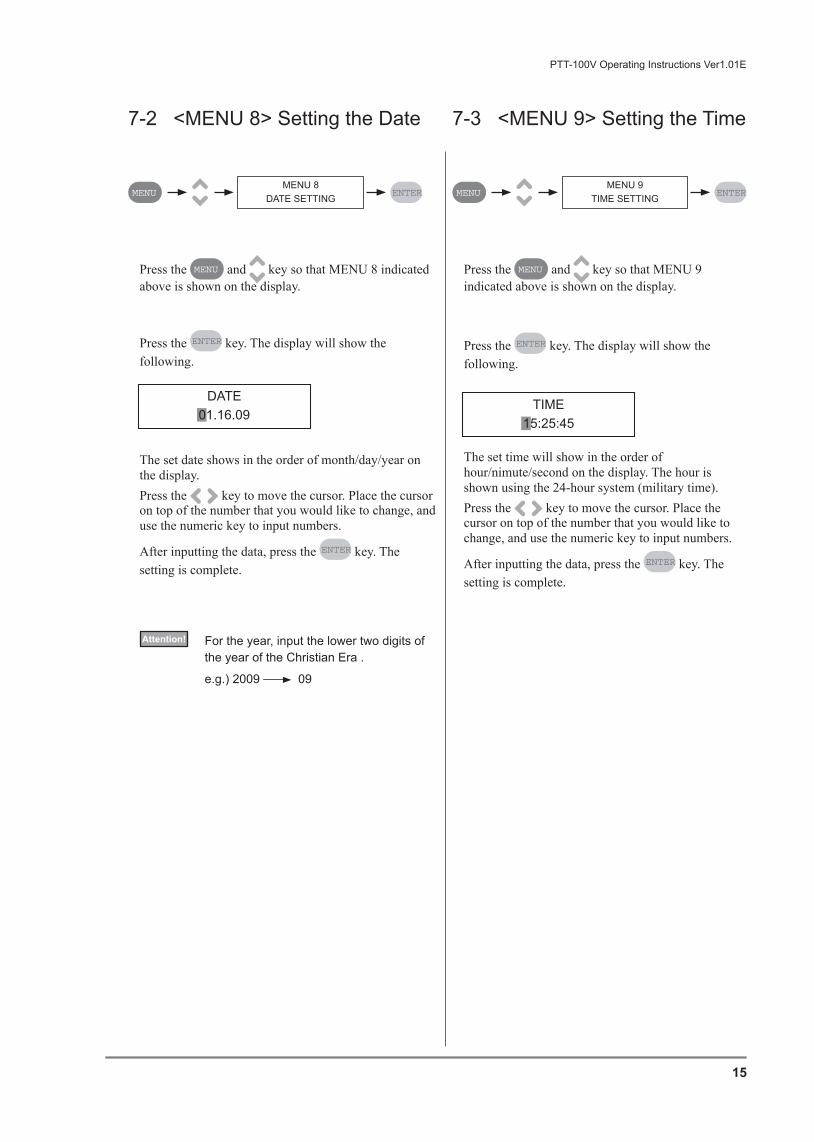
Press the MENU and key so that MENU 8 indicated above is shown on the display.
Press the ENTER key. The display will show the following.
The set date shows in the order of month/day/year on the display.Press the key to move the cursor. Place the cursor on top of the number that you would like to change, and use the numeric key to input numbers.
After inputting the data, press the ENTER key. The setting is complete.
Press the MENU and key so that MENU 9 indicated above is shown on the display.
Press the ENTER key. The display will show the following.
The set time will show in the order of hour/nimute/second on the display. The hour is shown using the 24-hour system (military time).Press the key to move the cursor. Place the cursor on top of the number that you would like to change, and use the numeric key to input numbers.
After inputting the data, press the ENTER key. The setting is complete.
7-2 <MENU 8> Setting the Date 7-3 <MENU 9> Setting the Time
MENU 8DATE SETTING
DATE01.16.09
MENU ENTERMENU 9
TIME SETTINGMENU ENTER
TIME15:25:45
Attention! For the year, input the lower two digits of the year of the Christian Era .
e.g.) 2009 09
PTT-100V Operating Instructions Ver1.01E
15

7-4 <MENU 10> Adjusting the Time
7-5 <MENU 11> Delete the On-Board Memory
MENU 10TIME ADJUSTMENU ENTER
ADJUST15:25:45
MENU 11INITIALIZE RAMMENU ENTER
INITIALIZE RAMPUSH <&> KEY
INITIALIZE RAMFINISH
The set time can be adjusted in the following directions in order to adjust the time precisely.
Press the MENU and key so that MENU 10 indicated above is shown on the display.
Press the ENTER key. The display will show the following.
How to set: Press the ENTER key when the second is at 00
to 29 to round off the second. Press the ENTER key when the second is at 30
to 59 to round up the second.
This machine can save up to 30 measured data to the machine on-board memory. Please use this function when you would like to delete the memory to avoid mixing up each measuring data etc. As the on-board memory will be completely deleted, connect the machine to the PC and make sure that the data is transferred to the PC before performing this menu.
Press the and keys at the same time in order to initialize the data. The on-board memory will be deleted and the following will be displayed.
Press the MENU and key so that MENU 11 indicated above is shown on the display.
Press the ENTER key. The display will show the following.
Attention! When the on-board memory become full, the oldest memory will be overwritten. So you may not have to delete the on-board memory unless you need to delete it.
Press the MENU button to return.
PTT-100V Operating Instructions Ver1.01E
16

This machine can choose the measuring condition from the below options.Before starting the operation, set the most suitable measuring condition to your test material and application.
8 Set the Measuring Condition
About the SEAL LINE Setting 1 LINE : The thin-film grip stops and finish measuring when the peel strength is stabilized after
starting the inspection. 2 LINES : The thin-film grip stops and finish measuring when the peel strength is stabilized,
becomes no-load, and then the peel strength becomes stable again. No Setting : The thin-film grip stops and finish measuring when it reaches to the end regardless of the
measured peel strength.
NOTE
PTT-100V Operating Instructions Ver1.01E
17
NENU
No.Title Setting contents Explanation
2 PEEL ORG 10mm (*)
25mm
The grip distance in the peel tester may be changed to 10mm (0.4") or 25mm (1"). For the highly extensible materials, choose 10mm.
3 UNIT SELECT N, Kg, LbThe unit can be selected among N, Kg, and
Lb.
4 PEEL MODEMaximum 50N# 00N(*) is invalid.
The minimum of average or minimum seal
strength settable for automatic pass/fail
determination.
The error message will be displayed if the
strength is under the set values.
5 SPEED SETTING300mm/ min (*)
200mm/ min
The peel speed can be selected between 300
and 200mm/min.
6 SEAL LINES
1 Line (*)
2 Lines
No setting
1 or 2-line modes to be able to test standard or
tandem-created sealse.g.)
Sealed with 1-line sealer : 1 LINE
Sealed with 2-line sealer: 2 LINES
Test the film strength : No setting
# Please refer to the "NOTE" below for the detail.
7 INSPECTION1
2
This mode is activated only when Administrator
and Operator ID is registered and activated.e.g.)
INSPECTION 1: Both VIU and PTT can be used.
INSPECTION 2: PTT cannot be used without the
VIU inspection
Asterisk mark (*) indicates the default setting.

The grip distance in the peel tester may be changed to 10mm (0.4 inches) or 25mm (1 inch).
Press ENTER when the desired distance is displayed on the screen. The setting is complete.
Press the MENU and key so that MENU 2 indicated above is shown on the display.
Press the ENTER key. The display will show the following.
Press the MENU and key so that MENU 3 indicated above is shown on the display.
Press the ENTER key. The display will show the following.
Press the key to switch the display among N, Kgf, and Lbf.
Press ENTER when the desired unit is displayed on the screen. The setting is complete. The unit for length
will be automatically set mm, mm, and inch to N, Kgf, and Lbf.
Press the MENU and key so that MENU 4 indicated above is shown on the display.
Press the ENTER key. The display will show the following.
Press the key to switch the display between MINIMUM and AVERAGE.
Input the desired minimum value using the numeric keys, and press ENTER to complete the setting.
Automatic pass/fail determination relies on either one
of MINIMUM or AVERAGE.
Press the MENU and key so that MENU 5 indicated above is shown on the display.
Press the ENTER key. The display will show the following.
Press the key to switch the display between “300mm/min” and “200mm/min.”
Press ENTER when the desired speed is displayed on the screen. The setting is complete.
8-1 <MENU 2> Chuck Distance 8-2 <MENU 3> Unit Select
8-3 <MENU 4> Peel Mode 8-4 <MENU 5> Peel Speed
MENU 2PEEL ORGMENU ENTER
PEEL ORG10mm
MENU 3UNIT SELECTMENU ENTER
UNITN
MENU 4PEEL MODEMENU ENTER
PEEL MINIMUM00 N
MENU 5SPEED SETTINGMENU ENTER
SPEED SETTING300mm/ min
PTT-100V Operating Instructions Ver1.01E
18

Press the MENU and key so that MENU 6 indicated above is shown on the display.
Press the ENTER key. The display will show the following.
Press the key to switch the display among “1 LINE”, “2 LINES”, and “NO SETTING.”
Press ENTER when the desired condition is displayed on the screen. The setting is complete.
Press the MENU and key so that MENU 7 indicated above is shown on the display.
Press the ENTER key. The display will show the following.
Press the key to switch the display between inspection modes 1 and 2.
Press ENTER when the desired mode is displayed on the screen. The setting is complete. For the detail of
each inspection mode, please refer to the chart of “8 Set the Measuring Condition.”
8-5 <MENU 6> Seal Lines 8-6 <MENU 7> Inspection
MENU 6SEAL LINESMENU ENTER
SEAL LINES1 LINE
MENU 7INSPECTION MODEMENU ENTER
INSPECTION1
PTT-100V Operating Instructions Ver1.01E
19

Please prepare for one sealed sterilized bag.
Inspect the seal surface with the VIU
1 Press the button to display the following.
After setting the measuring condition, please follow the directions below to perform visual inspection and peel tensile testing correctly.
9 Proper Use of the Machine and Measuring Method
9-1-1 Perform the visual inspection with VIU
9-1 Operation Pattern 1 - Without the Administrator ID -
Sealing surface
VIU INSPECTIONFILM OFF
Under the operation pattern 1, the visual inspection and peel tensile testing can be performed individually.
Operation pattern 1 applies when: Only the Administrator ID is registered. Only the Operator ID is registered. No ID is registered. Both Administrator and Operator IDs are registered and the Inspection Mode 1 is selected
Attention! The MENU 7 INSPECTION MODE is activated only when the Administrator ID is registered and activated. Under the Inspection Mode 2, the visual inspection and peel tensile test becomes one set of operation. Please note that the Operators cannot change the setting when the Administrator ID is registered.
Attention! Please note that the Operators cannot change the setting when the Administrator ID is registered and activated.
PTT-100V Operating Instructions Ver1.01E
20

2 LED lamps of the VIU unit turns ON. When they are ON, insert the sterilized bag to
the groove under the VIU lens.
3 Inspect the sealing surface of the inserted sterilized bag. When the bag/ film is inserted, the display will show the following.
4 The PASS/ FAIL buttons will be activated after 3 seconds the bag is inserted and the display will show “FILM ON.”
Press button when there are no defects in sealing.
Press button when the sealing defect is perceived. The following will be displayed.
Press the corresponding number of the failure out of 9 possible seal failure causations. For the detail of the failure causations, please refer to the attached card. VIU inspection is now complete.
VIU INSPECTIONFILM ON
VIU FAILPUSH NUMBER KEY
PTT-100V Operating Instructions Ver1.01E
21

Please prepare for one sealed sterilized bag.
1 Prepare for a film-cutting template, which is included in the accessories.
Caution To cut the specimen, you need to use a box cutter. Be care ful not to cut yourself.
How to cut a specimenCut a specimen as specified in ASTM 88.By using a cutting template, you can cut the film in the size of 1 inch width.
2 Place a film-cutting template on the sealed sterilized bag. When the PEEL ORG setting is 10mm (0.4 in.), cut the film using a template for 10mm. Likewise, when the PEEL ORG setting is 25mm (1 in.), cut the film using a template for 25mm. Please refer “The size of specimens” below for the detailed sizes.
The size of specimens
9-1-2 Perform the peel tensile testing with PTT
Sealing surface
When the PEEL ORG setting is 10mm (0.4”)
When the PEEL ORG setting is 25mm (1”)
Sealing surface
Sealing surface
Sterilized bag
Sealing surface
PEEL ORG setting 10mm (0.4”)
PEEL ORG setting 25mm (1”)
45mm
25mm
25mm
35mm
PTT-100V Operating Instructions Ver1.01E
22

Perform peel tensile test
1 Press the button. When the grip is not in the starting position, the following will be shown on the display.
Caution When the grip is moving, please be careful not to pinch your fingers.
The display will show the following when the grip is at the initial position.
2 Insert the cut, film portion of the sterilized bag to the thin-film grips.
Please not the following conditions when doing so:・ Insert the specimen so it stays within the
width of grip. Inserting it slantwise or not inserted correctly will negatively affect the test result.
・ The load cell (sensor) may damage if a force exceeding rated capacity is applied to the measuring axis. Be careful when attaching the thin-film grip on the measurement side.
・ When testing the sealed film, be cure that the sealing surface comes in the middle of the grips.
Attention! By using a specimen setting gauge, it will be easier to set a specimen.
ORG RETURN
FILM SETPUSH START KEY
Sealing surface
Specimen installed to the grips
PTT-100V Operating Instructions Ver1.01E
23

3 Press button. The display will show the following.
After the START button is pressed・ The applied load is ・ The DC motor starts moving and each
parameters such as peel speed, displacement, and maximum peel strength will be displayed.
・ It stops measuring when there is no peel tensile load.
・ The test result will be shown on the display and the grip returns to the initial position automatically.
・ Remove the inserted specimen after the grip returns to the initial position.
Caution When the grip is moving, please be careful not to pinch your fingers.
Attention! When the error occurs during the operation, the grip will not return to the initial position. It stops at where the inspection is stopped.
TIPS Press button to stop the inspection.
V=300mm/m [N]L=0.23.2mm F=007.2
Peel speed
Maximum peel strengthDisplacement
PTT-100V Operating Instructions Ver1.01E
24
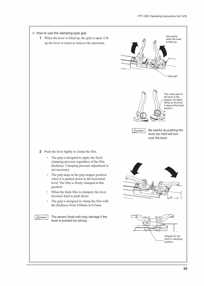
How to use the clamping-type grip1 When the lever is lifted up, the grip is open. Lift
up the lever to insert or remove the specimen.
2 Push the lever lightly to clamp the film.
・ The grip is designed to apply the fixed clamping pressure regardless of the film thickness. Clamping pressure adjustment is not necessary.
・ The grip stops at the grip stopper position when it is pushed down to the horizontal level. The film is firmly clamped at this position.
・ When the thick film is clamped, the lever becomes hard to push down.
・ The grip is designed to clamp the film with the thickness from 0.04mm to 0.2mm.
Caution The sensor (load-cell) may damage if the lever is pushed too strong.
Caution Be careful as pushing the lever too hard will turn over the lever.
Grip opens when the lever is lifted up.
Grip part
The cutout part of the lever is the stopper. By lightly lifting up the lever, it stops at the fixed position.
Stopper for the lever in clamping position.
PTT-100V Operating Instructions Ver1.01E
25

How to use the specimen setting gaugeBy using the specimen setting gauge, it will be easier to insert the specimen to the thin-film grips. Please note that the specimen setting gauge is not suitable for the highly flexible materials.
1 Insert the specimen to the specimen setting gauge as in the right illustration.
2 Hold the specimen setting gauge and insert the specimen to the thin-film grips.
3 While holding the specimen setting gauge, push down the levers to clamp the specimen with the grips.
Specimen setting gauge
Clamp these parts to the thin-film grips.
Specimen setting gauge
PTT-100V Operating Instructions Ver1.01E
26

1 Follow the direction of “9-1-1 Perform the visual inspection with VIU” procedure 1 -3.
Under the operation pattern 2, the visual inspection and peel tensile testing are one set of operation.Inspection condition cannot be changed by the Operators. Only the administrator is authorized to do so.
Operation pattern 2 applies when: Both Administrator and Operator IDs are registered and the Inspection Mode 2 is selected
2 The PASS/ FAIL buttons will be activated after 3 seconds the bag is inserted and the display will show “FILM ON.”
Press button when the sealing defect is perceived. The following will be displayed.
Restart the machine by turning OFF and ON the power switch. The display will show the screen to input the Administrator password. Call the Administrator. Now the VIU inspection is complete.
Press the corresponding number of the failure out of 10 possible seal failure causations. The following will be displayed.
Press button when there are no defects in sealing. The following will be displayed.
The machine automatically moves to the peel tensile test.
1 Follow the direction of “9-1-2 Perform the peel tensile test with PTT.”
9-2 Operation Pattern 2 - With the Administrator ID -
9-2-1 Perform the visual inspection with VIU
9-2-2 Perform the peel tensile test with PTT
ERROR 60POWER ON RESTART
VIU FAILPUSH NUMBER KEY
ORG RETURN
PTT-100V Operating Instructions Ver1.01E
27

The load cell accuracy will decline with the number of use and passage of time.We recommend to perform calibration every 6 months or every year so that you may continue to use the load cell in a better condition. For the frequency and cost of the calibration, please contact your local dealer.
PTT-100V can diplay/manage measured test result by connecting to the PC using a USB cable.For the installation of the PC application for PTT-100V and its operating method, please contact Van der Stahl Scientific, Inc.
10 Transferring Data to the PC
11 About Calibration
PTT-100V Operating Instructions Ver1.01E
28

CR2032 +
You will need: a Philips screwdriverReplace when: “BATTERY ERROR” or
“TIMER ERROR” is displayed as in the illustration on the right.
The battery works to back up the date and time setting. When the battery voltage drops, “BATTERY ERROR” or “TIMER ERROR” will be displayed. When this is displayed, replace the battery. Lithium button battery used: CR2302
Caution Always turn the power switch off and unplug the power cord from the outlet before replacing parts.
1 Remove the battery cover located at the bottom plate of the machine.
2 When removing the button cell battery from the battery case, push the battery further in toward the back before pushing it upward to remove it. When inserting the button cell battery, insert the battery so that the plus (+) side faces upward in the battery case and that the case and the battery lie parallel to each other. If the battery is not level when inserting, it will not insert properly.
3 After replacing the battery, “TIME ERROR” will be displayed. Adjust the date and time as they will be initialized.
Attention! If “TIMER ERROR” displays even after replacing the battery and adjusting the date and time, the electric board damage may be suspected.
12 Replacing the Routine Maintenance Parts12-1 Replacing the battery
DATE<16.6.09>BATTERY ERROR
DATE<16.6.09>TIMER ERROR
Button-cell battery
Button-cell battery cover
Removing the battery:
Inserting the battery:
Top view Side view
Lift upInsert further into the back before lifting it up.
Battery Insert direction
Insert further into the back
CaseSide viewRear view
Battery
Plus (+) side
Case
PTT-100V Operating Instructions Ver1.01E
29

PTT-100V uses the fuse with the following specification: Maximum rated voltage: 250V Maximum rated current: 1A Type: FAST
You will need: a flathead screwdriver
1 Fuse holder is located above the inlet for the power cord. Turn the cap counterclockwise using a flathead screwdriver and remove the fuse holder.
2 Set a new fuse to the fuse holder, and return it to where it was.
Caution Be sure to use the fuse that meets the specified voltage/ current/ type.
Turn OFF the power switch and unplug the cord before replacing the fuse.
Do not short-circuit the fuse holder.
12-2 Replacing the Fuse
Remove Install
Remove
Install
Fuse holder
Power cord connector
Flathead screwdriver
PTT-100V Operating Instructions Ver1.01E
30

If you notice the following in regards to the VIU Unit Photo Sensor, adjust the volume control:
●The display does not change from FILM OFF to FILM ON when film is inserted during VIU inspection.
●The display remains ON even when no film is being inserted.
You will need: a precision screwdriver
Adjusting the Volume1 Remove the button-cell battery cover. Please
refer to “12-1 Replacing the batter” for the detail.2 Have a precision screwdriver ready. Adjust the
volume by turning a sensitivity adjustment volume.
3 Press button and insert a sealed sterilized bag into VIU.
4 Verify that the light turns OFF when the sterilized bag is removed, and that it turns ON when the sterilized bag is inserted.
13 Adjusting the VIU Photosensor
Volume adjustment
Minimize the sensitivity adjustment volume (turn counterclockwise). At this time, the light is turned OFF.
Gradually increase the sensitivity adjustment volume from its minimum state (turn clockwise). Set at the position where the light switches from OFF to ON.
Light (RED)Sensitivity adjustment volume
Insert a precision screwdriver to the hole here.
The photo sensor is located inside the hole.
PTT-100V Operating Instructions Ver1.01E
31

14 Electric Diagram
PTT-100V Operating Instructions Ver1.01E
32
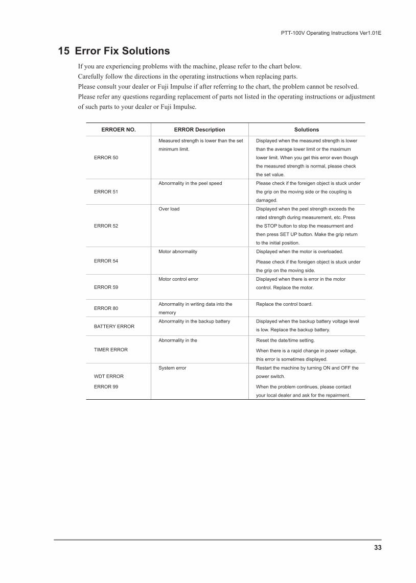
If you are experiencing problems with the machine, please refer to the chart below.Carefully follow the directions in the operating instructions when replacing parts.Please consult your dealer or Fuji Impulse if after referring to the chart, the problem cannot be resolved. Please refer any questions regarding replacement of parts not listed in the operating instructions or adjustment of such parts to your dealer or Fuji Impulse.
15 Error Fix Solutions
PTT-100V Operating Instructions Ver1.01E
33
ERROER NO. ERROR Description Solutions
ERROR 50
Measured strength is lower than the set
minimum limit.
Displayed when the measured strength is lower
than the average lower limit or the maximum
lower limit. When you get this error even though
the measured strength is normal, please check
the set value.
ERROR 51
Abnormality in the peel speed Please check if the foreigen object is stuck under
the grip on the moving side or the coupling is
damaged.
ERROR 52
Over load Displayed when the peel strength exceeds the
rated strength during measurement, etc. Press
the STOP button to stop the measurment and
then press SET UP button. Make the grip return
to the initial position.
ERROR 54
Motor abnormality Displayed when the motor is overloaded.
Please check if the foreigen object is stuck under
the grip on the moving side.
ERROR 59
Motor control error Displayed when there is error in the motor
control. Replace the motor.
ERROR 80Abnormality in writing data into the
memory
Replace the control board.
BATTERY ERRORAbnormality in the backup battery Displayed when the backup battery voltage level
is low. Replace the backup battery.
TIMER ERROR
Abnormality in the Reset the date/time setting.
When there is a rapid change in power voltage,
this error is sometimes displayed.
WDT ERROR
ERROR 99
System error Restart the machine by turning ON and OFF the
power switch.
When the problem continues, please contact
your local dealer and ask for the repairment.

Y7003 SEP 2009 1st EditionPTT-100V Operating Instructions Ver1.01E