Simple Mechanisms
73
Chapter 5 Simple Mechanisms September 26, 2015 Mohammad Suliman Abuhaiba, Ph.D., PE 1
Transcript of Simple Mechanisms
Chapter 5
Simple Mechanisms
September 26, 2015
Mohammad Suliman Abuhaiba, Ph.D., PE1

Assignment #1
All questions at the end of chapter
1st Exam: Monday 5/10/2015
September 26, 2015
Mohammad Suliman Abuhaiba, Ph.D., PE
2
Kinematic Link or Element
kinematic link (link) or element:Each part of a machine, which
moves relative to some other
part.
A link need not to be a rigid body
It must be a resistant body
September 26, 2015
Mohammad Suliman Abuhaiba, Ph.D., PE
3
Kinematic Link or Element
A resistant body: capable of
transmitting required forces with
negligible deformation.
A link has two characteristics:
1. It should have relative motion
2. It must be a resistant body
September 26, 2015
Mohammad Suliman Abuhaiba, Ph.D., PE
4
Types of Links
1. Rigid link: does not undergo anydeformation while transmitting motion
2. Flexible link: partly deformed in a mannernot to affect the transmission of motion
Example: belts, ropes, chains and wires
3. Fluid link: formed by having a fluid in acontainer and motion is transmitted
through the fluid pressure
Example: hydraulic presses, jacks and brakes
September 26, 2015
Mohammad Suliman Abuhaiba, Ph.D., PE
5

Structure and a Machine
Structure: assembly of a number
of resistant bodies having no
relative motion between them
and meant for carrying loads
having straining action.
Examples: A railway bridge, a roof
truss, machine frames
September 26, 2015
Mohammad Suliman Abuhaiba, Ph.D., PE
6
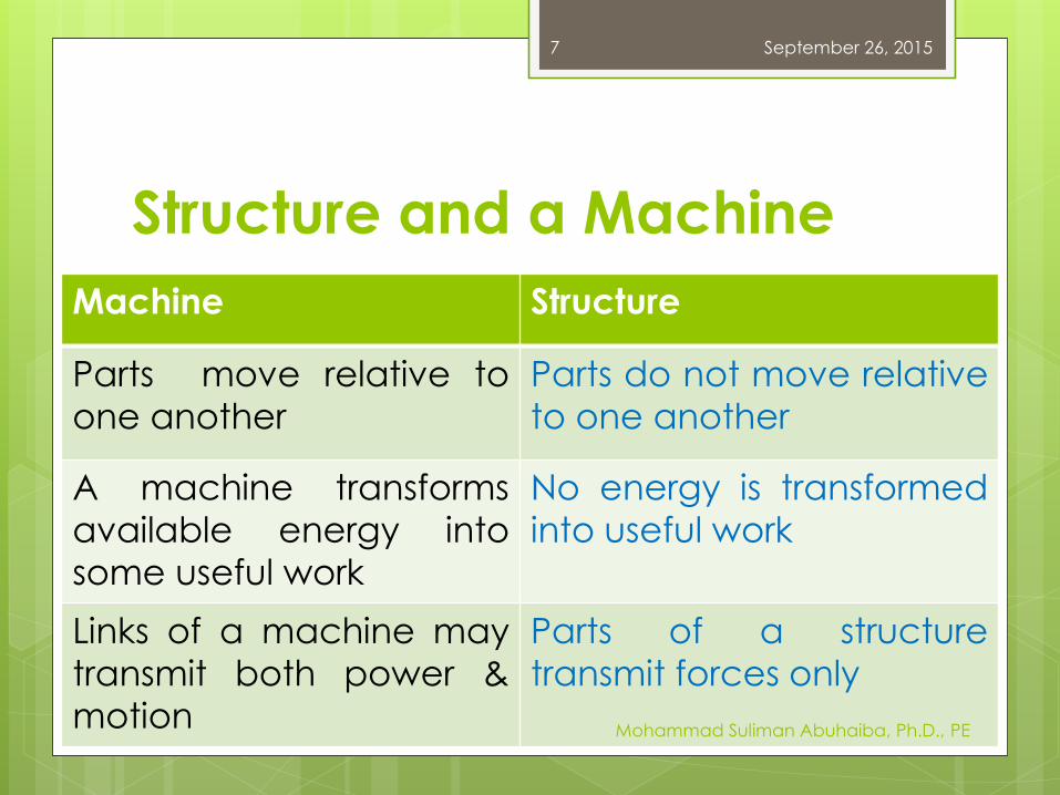
Machine Structure
Parts move relative to
one another
Parts do not move relative
to one another
A machine transforms
available energy into
some useful work
No energy is transformed
into useful work
Links of a machine may
transmit both power &
motion
Parts of a structure
transmit forces only
Structure and a Machine
September 26, 2015
Mohammad Suliman Abuhaiba, Ph.D., PE
7
Kinematic Pair
A pair: two links of a machine, in
contact with each other.
kinematic pair: the relative motionbetween the links is completely or
successfully constrained
September 26, 2015
Mohammad Suliman Abuhaiba, Ph.D., PE
8

Types of Constrained Motions
1. Completely constrained motion
2. Incompletely constrained motion
3. Successfully constrained motion
September 26, 2015
Mohammad Suliman Abuhaiba, Ph.D., PE
9
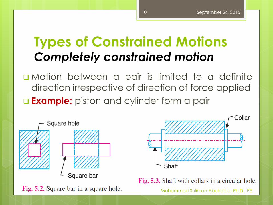
Types of Constrained MotionsCompletely constrained motion
Motion between a pair is limited to a definite
direction irrespective of direction of force applied
Example: piston and cylinder form a pair
September 26, 2015
Mohammad Suliman Abuhaiba, Ph.D., PE
10
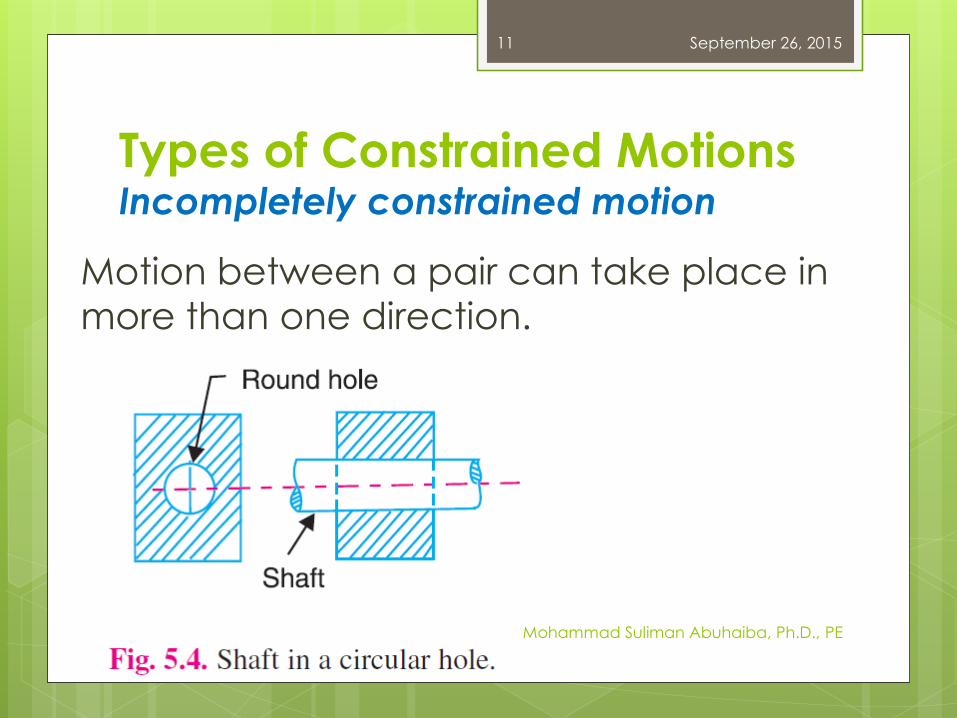
Types of Constrained MotionsIncompletely constrained motion
Motion between a pair can take place in
more than one direction.
September 26, 2015
Mohammad Suliman Abuhaiba, Ph.D., PE
11
Types of Constrained MotionsSuccessfully constrained motion
Motion between elements, forming a pair is
such that the constrained motion is not
completed by itself, but by some other
means
September 26, 2015
Mohammad Suliman Abuhaiba, Ph.D., PE
12
Types of Constrained MotionsSuccessfully constrained motion
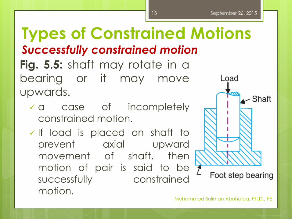
Fig. 5.5: shaft may rotate in a
bearing or it may move
upwards.
a case of incompletely
constrained motion.
If load is placed on shaft to
prevent axial upward
movement of shaft, then
motion of pair is said to be
successfully constrained
motion.
September 26, 2015
Mohammad Suliman Abuhaiba, Ph.D., PE
13
Classification of Kinematic Pairs
1. According to type of relative motion between elements
a. Sliding pair
b. Turning pair
c. Rolling pair
d. Screw pair
e. Spherical pair
2. According to type of contact between elements
a. Lower pair
b. Higher pair
3. According to type of closure
a. Self closed pair
b. Force - closed pair
September 26, 2015
Mohammad Suliman Abuhaiba, Ph.D., PE
14
Classification of Kinematic PairsAccording to type of relative motion between elements
a. Sliding pair
one pair can only slide relative to the
other
completely constrained motion
Examples:
Piston & cylinder
Tail stock on lathe bed
September 26, 2015
Mohammad Suliman Abuhaiba, Ph.D., PE
15
Classification of Kinematic PairsAccording to type of relative motion between elements
b. Turning pair
One pair can only turn or revolve about a
fixed axis of another link
Completely constrained motion
Examples:
Crankshaft in a journal bearing in an engine
Lathe spindle supported in head stock
September 26, 2015
Mohammad Suliman Abuhaiba, Ph.D., PE
16
Classification of Kinematic PairsAccording to type of relative motion between elements
c. Rolling pair
One pair rolls over another fixed link
Example: Ball and roller bearings
d. Screw pair
One element can turn about the
other by screw threads
Example: Lead screw of a lathe with
nut
September 26, 2015
Mohammad Suliman Abuhaiba, Ph.D., PE
17
Classification of Kinematic PairsAccording to type of relative motion between
elements
e. Spherical pair
One element (with spherical shape)
turns or swivels about the other fixed
element
Examples:
Ball and socket joint
Attachment of a car mirror
Pen stand
September 26, 2015
Mohammad Suliman Abuhaiba, Ph.D., PE
18
Classification of Kinematic PairsAccording to type of contact between the elements
a. Lower pair
Two elements of pair have surface
contact when relative motion takes
place
Surface of one element slides over
surface of the other
Examples: Sliding pairs, turning pairs
and screw pairs
September 26, 2015
Mohammad Suliman Abuhaiba, Ph.D., PE
19
Classification of Kinematic PairsAccording to type of contact between the elements
b. Higher pair
Two elements of a pair have a line or point
contact when relative motion takes place
Motion between the two elements is partly
turning and partly sliding
Examples:
A pair of friction discs
Toothed gearing
Belt and rope drives
Ball and roller bearings, and cam & follower
September 26, 2015
Mohammad Suliman Abuhaiba, Ph.D., PE
20
Classification of Kinematic PairsAccording to type of closure
a. Self closed pair
Two elements of a pair are connected
together mechanically in such a way
that only required kind of relative
motion occurs.
Lower pairs are self closed pair
September 26, 2015
Mohammad Suliman Abuhaiba, Ph.D., PE
21

Classification of Kinematic PairsAccording to type of closure
b. Force - closed pair
Two elements of a pair are not
connected mechanically but are kept
in contact by action of external forces
Example: cam & follower, kept in
contact by the forces exerted by
spring & gravity
September 26, 2015
Mohammad Suliman Abuhaiba, Ph.D., PE
22
Kinematic Chain (KC)
A kinematic chain:
A combination of kinematic pairs, joined
in such a way that each link forms a part
of two pairs
Relative motion between links or
elements is completely or successfully
constrained
September 26, 2015
Mohammad Suliman Abuhaiba, Ph.D., PE
23
Kinematic Chain (KC)
Example:
Crankshaft of engine forms a kinematic
pair with the bearings which are fixed in
a pair
ConRod with crank forms a 2nd pair
Piston with ConRod forms a 3rd pair
Piston with cylinder forms a 4th pair
Total combination of these links is a KC
September 26, 2015
Mohammad Suliman Abuhaiba, Ph.D., PE
24
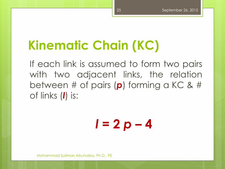
If each link is assumed to form two pairs
with two adjacent links, the relation
between # of pairs (p) forming a KC & #
of links (l) is:
l = 2 p – 4
Kinematic Chain (KC)
September 26, 2015
Mohammad Suliman Abuhaiba, Ph.D., PE
25
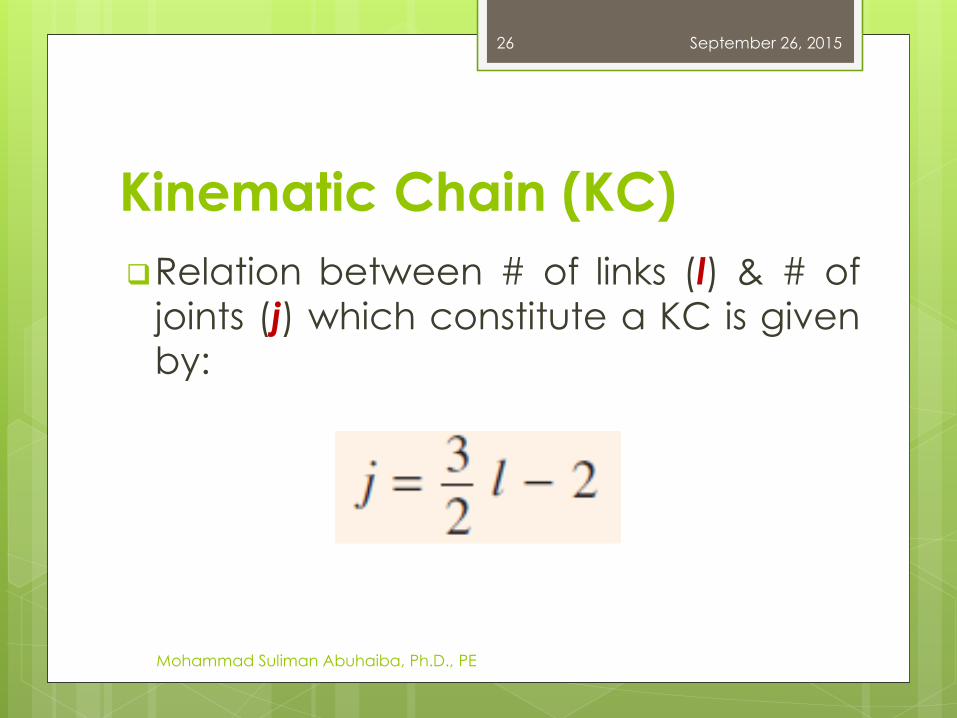
Relation between # of links (l) & # of
joints (j) which constitute a KC is givenby:
Kinematic Chain (KC)
September 26, 2015
Mohammad Suliman Abuhaiba, Ph.D., PE
26
Kinematic Chain (KC)
Above Equations are applicable
only to KC, in which lower pairs are
used
These equations may be applied to
KC, in which higher pairs are used:
each higher pair = two lower pairs with
an additional element or link
September 26, 2015
Mohammad Suliman Abuhaiba, Ph.D., PE
27
Kinematic Chain (KC)Examples
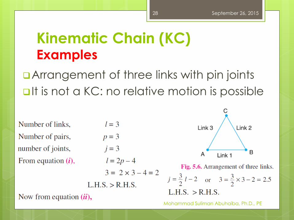
Arrangement of three links with pin joints
It is not a KC: no relative motion is possible
September 26, 2015
Mohammad Suliman Abuhaiba, Ph.D., PE
28
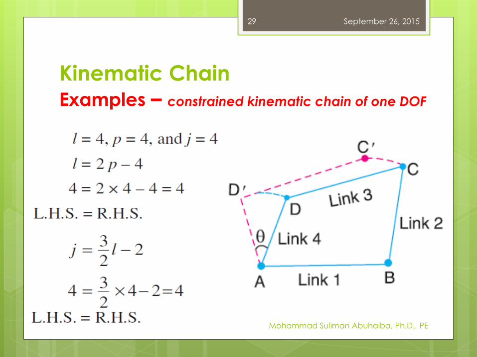
Kinematic Chain
Examples – constrained kinematic chain of one DOF
September 26, 2015
Mohammad Suliman Abuhaiba, Ph.D., PE
29
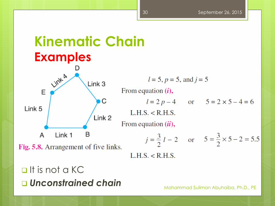
Kinematic ChainExamples
It is not a KC
Unconstrained chain
September 26, 2015
Mohammad Suliman Abuhaiba, Ph.D., PE
30
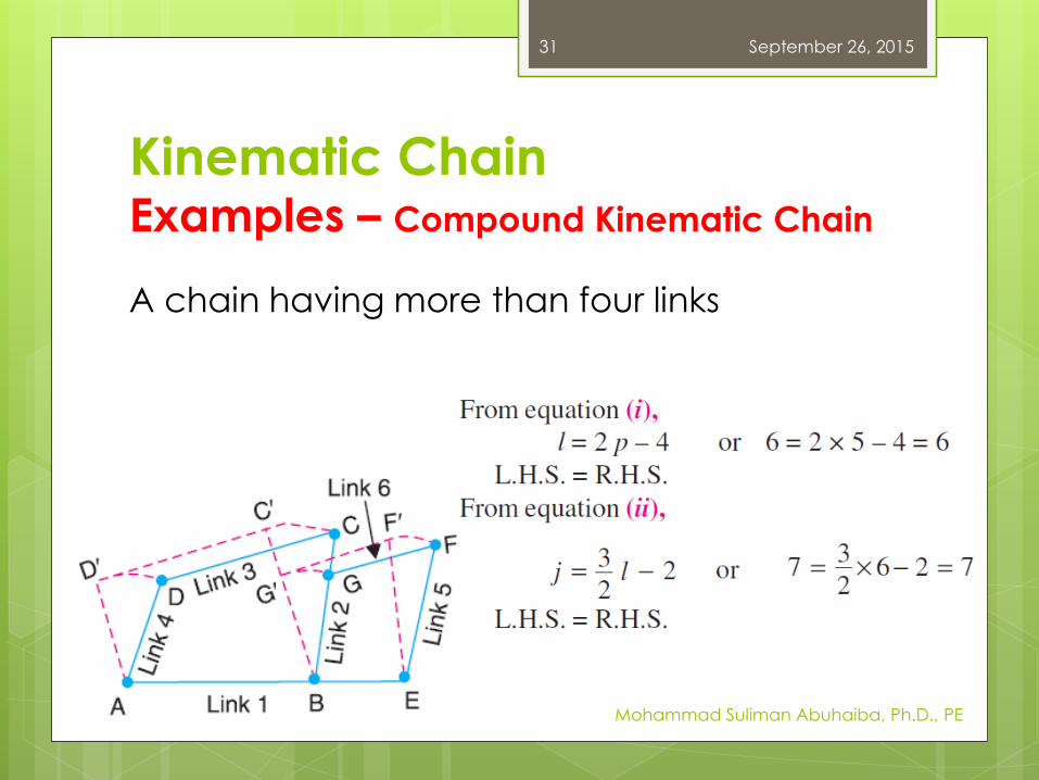
Kinematic ChainExamples – Compound Kinematic Chain
September 26, 2015
Mohammad Suliman Abuhaiba, Ph.D., PE
31
A chain having more than four links
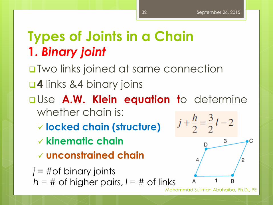
Types of Joints in a Chain1. Binary joint
Two links joined at same connection
4 links &4 binary joins
Use A.W. Klein equation to determine
whether chain is:
locked chain (structure)
kinematic chain
unconstrained chain
September 26, 2015
Mohammad Suliman Abuhaiba, Ph.D., PE
32
j = #of binary joints
h = # of higher pairs, l = # of links
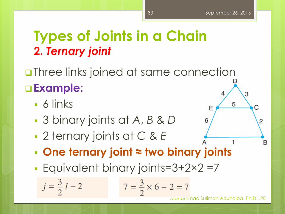
Types of Joints in a Chain2. Ternary joint
Three links joined at same connection
Example:
6 links
3 binary joints at A, B & D
2 ternary joints at C & E
One ternary joint ≈ two binary joints
Equivalent binary joints=3+2×2 =7
September 26, 2015
Mohammad Suliman Abuhaiba, Ph.D., PE
33
Types of Joints in a Chain3. Quaternary joint
Four links joined at same connection
Equivalent to three binary joints
When l number of links are joined at
same connection, joint is equivalent to (l
– 1) binary joints
September 26, 2015
Mohammad Suliman Abuhaiba, Ph.D., PE
34

Types of Joints in a Chain3. Quaternary joint
Fig. 5.12 (a):
one binary joint at D
4 ternary joints at A, B, E and F
2 quaternary joints at C & G
# of binary joints in chain are
September 26, 2015
Mohammad Suliman Abuhaiba, Ph.D., PE
35
Chain is not a KC
locked chain: structure
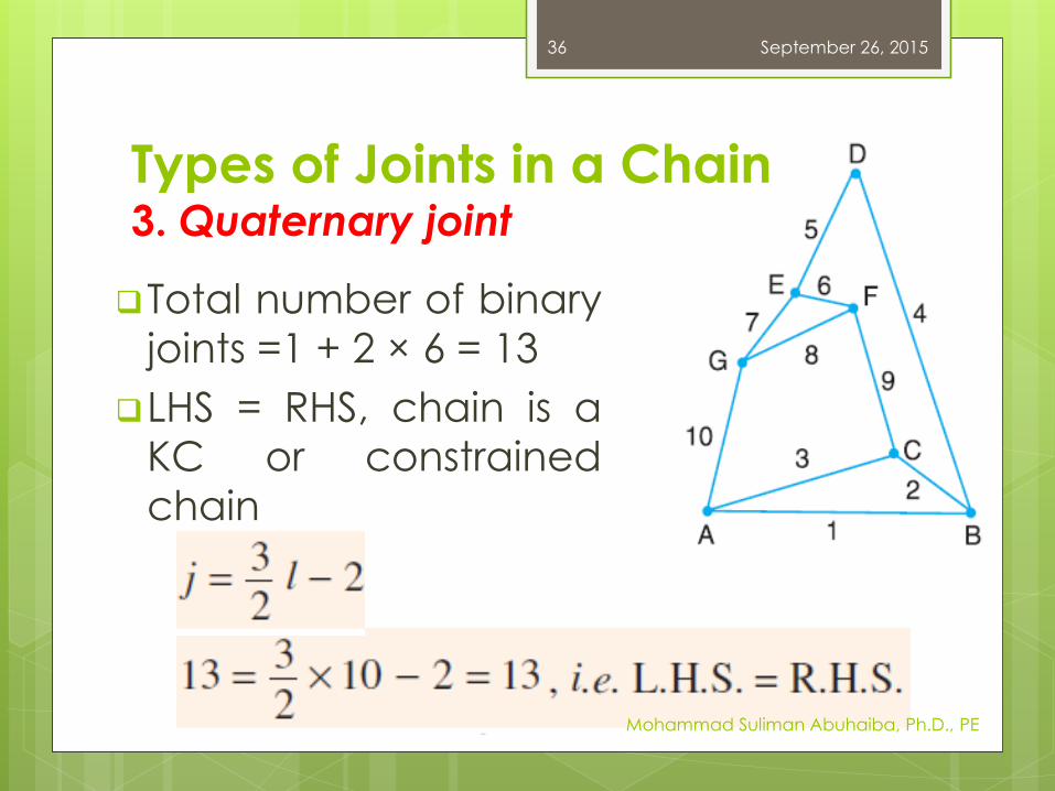
Types of Joints in a Chain3. Quaternary joint
Total number of binary
joints =1 + 2 × 6 = 13
LHS = RHS, chain is a
KC or constrained
chain
September 26, 2015
Mohammad Suliman Abuhaiba, Ph.D., PE
36
Mechanism
Mechanism: one of the links of a KC is fixed
Used for transmitting or transforming
motion e.g. engine indicators, typewriter
etc.
Simple mechanism: 4 links
Compound mechanism: > 4 links
Machine: When a mechanism is required totransmit power or to do some particular
type of work
September 26, 2015
Mohammad Suliman Abuhaiba, Ph.D., PE
37
Number of DOF for Plane Mechanisms
DOF: number of input parameters which
must be independently controlled in
order to bring the mechanism into a
useful engineering purpose
September 26, 2015
Mohammad Suliman Abuhaiba, Ph.D., PE
38
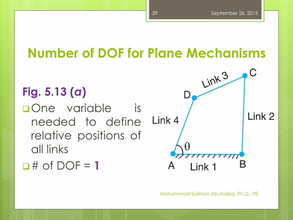
Number of DOF for Plane Mechanisms
Fig. 5.13 (a)
One variable is
needed to define
relative positions of
all links
# of DOF = 1
September 26, 2015
Mohammad Suliman Abuhaiba, Ph.D., PE
39

Number of DOF for Plane Mechanisms
Fig. 5.13 (b)
Two variables q1 &
q2 are needed tocompletely define
relative positions
of all links
# of DOF = 2
September 26, 2015
Mohammad Suliman Abuhaiba, Ph.D., PE
40
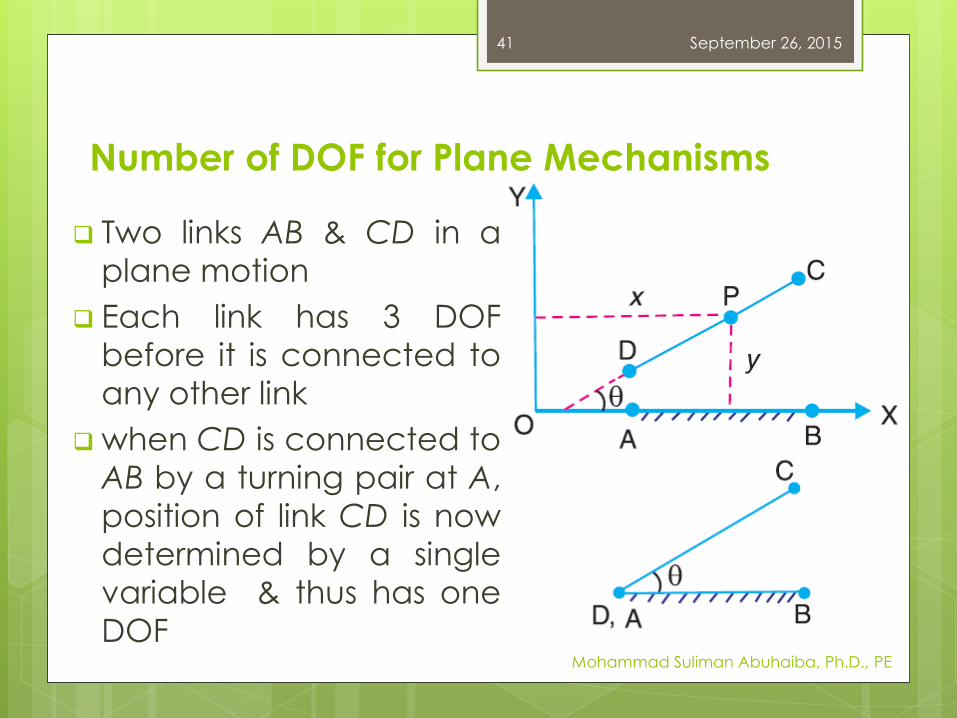
Number of DOF for Plane Mechanisms
Two links AB & CD in a
plane motion
Each link has 3 DOF
before it is connected to
any other link
when CD is connected to
AB by a turning pair at A,
position of link CD is now
determined by a single
variable & thus has one
DOF
September 26, 2015
Mohammad Suliman Abuhaiba, Ph.D., PE
41
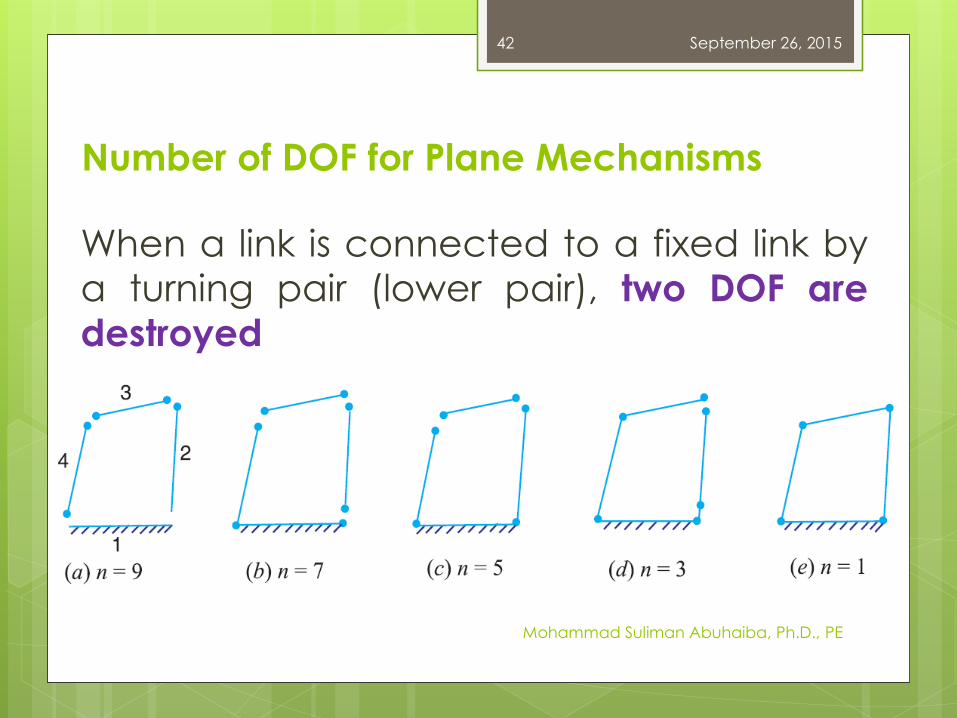
Number of DOF for Plane Mechanisms
When a link is connected to a fixed link by
a turning pair (lower pair), two DOF are
destroyed
September 26, 2015
Mohammad Suliman Abuhaiba, Ph.D., PE
42
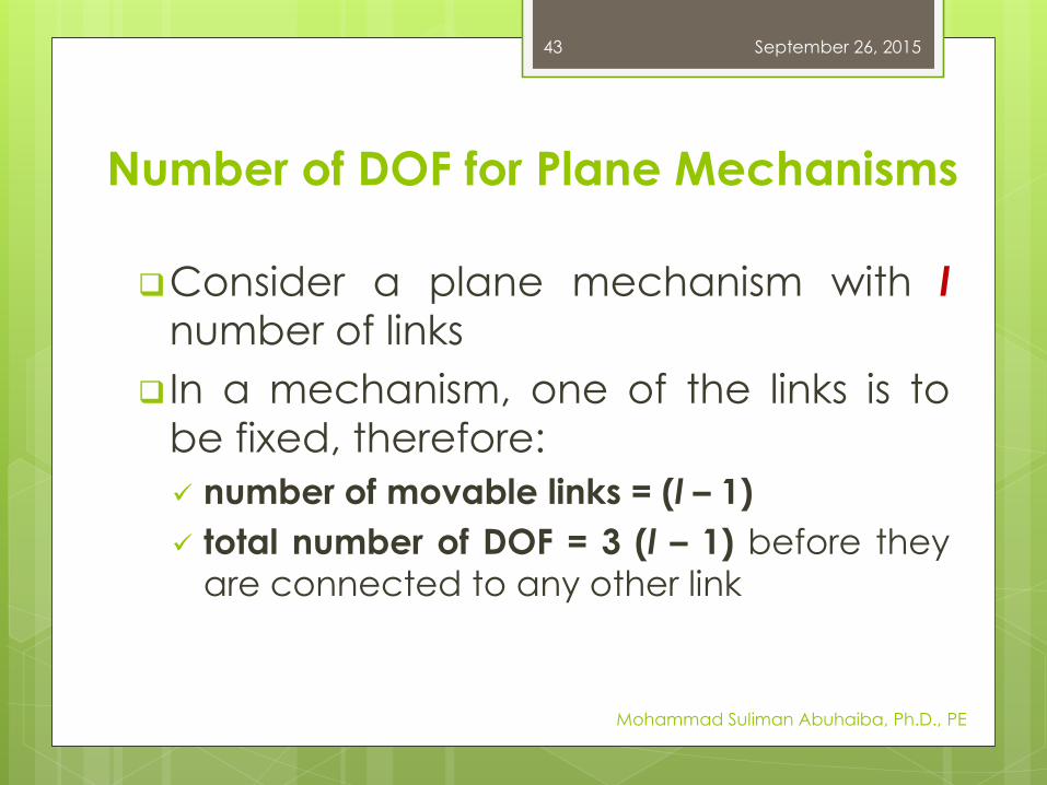
Number of DOF for Plane Mechanisms
Consider a plane mechanism with lnumber of links
In a mechanism, one of the links is to
be fixed, therefore:
number of movable links = (l – 1)
total number of DOF = 3 (l – 1) before they
are connected to any other link
September 26, 2015
Mohammad Suliman Abuhaiba, Ph.D., PE
43
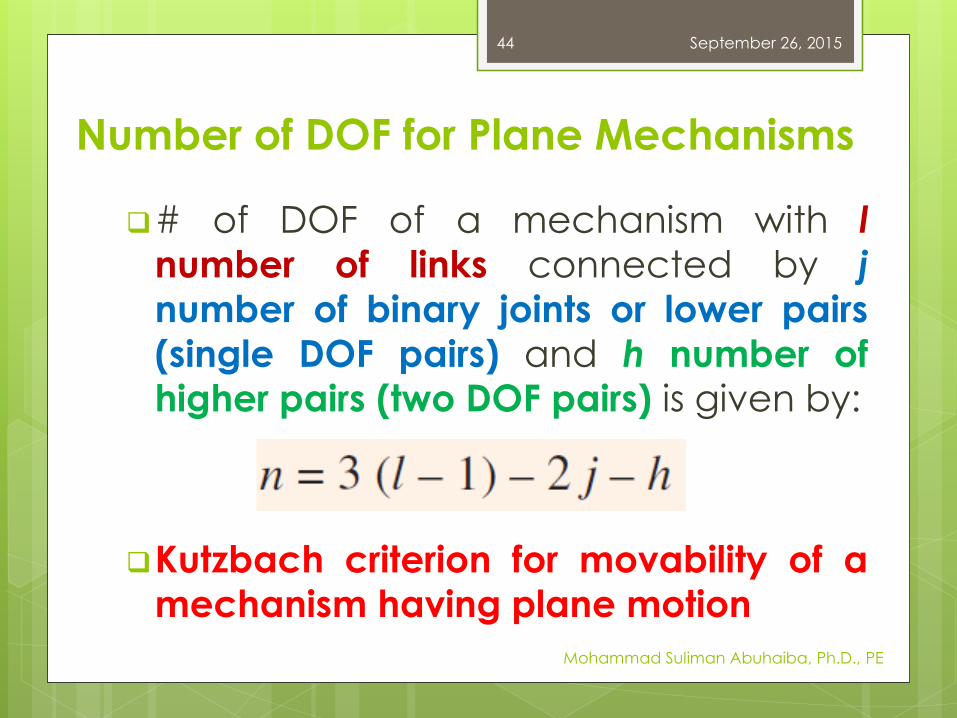
Number of DOF for Plane Mechanisms
# of DOF of a mechanism with l
number of links connected by j
number of binary joints or lower pairs
(single DOF pairs) and h number ofhigher pairs (two DOF pairs) is given by:
Kutzbach criterion for movability of amechanism having plane motion
September 26, 2015
Mohammad Suliman Abuhaiba, Ph.D., PE
44
Application of Kutzbach
Criterion to Plane Mechanisms
September 26, 2015
Mohammad Suliman Abuhaiba, Ph.D., PE
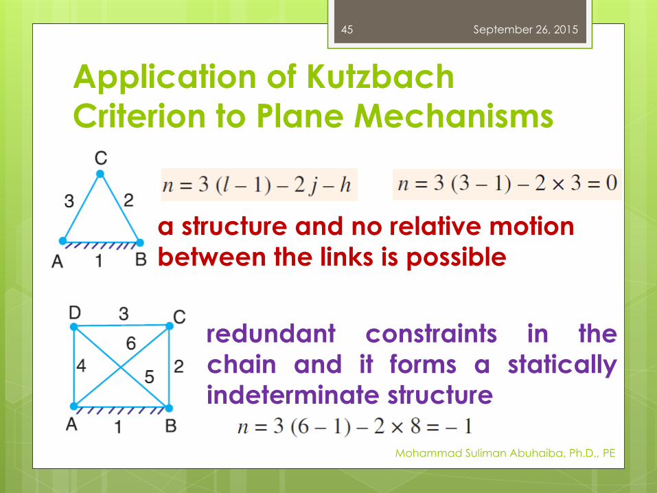
45
a structure and no relative motion
between the links is possible
redundant constraints in the
chain and it forms a statically
indeterminate structure

Application of Kutzbach
Criterion to Plane Mechanisms
September 26, 2015
Mohammad Suliman Abuhaiba, Ph.D., PE
46
Application of Kutzbach
Criterion to Plane Mechanisms
September 26, 2015
Mohammad Suliman Abuhaiba, Ph.D., PE
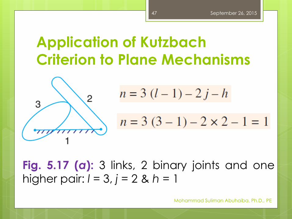
47
Fig. 5.17 (a): 3 links, 2 binary joints and onehigher pair: l = 3, j = 2 & h = 1
Application of Kutzbach
Criterion to Plane Mechanisms
September 26, 2015
Mohammad Suliman Abuhaiba, Ph.D., PE
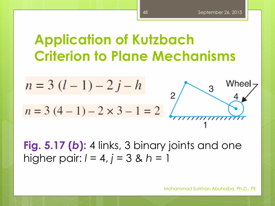
48
Fig. 5.17 (b): 4 links, 3 binary joints and one higher pair: l = 4, j = 3 & h = 1
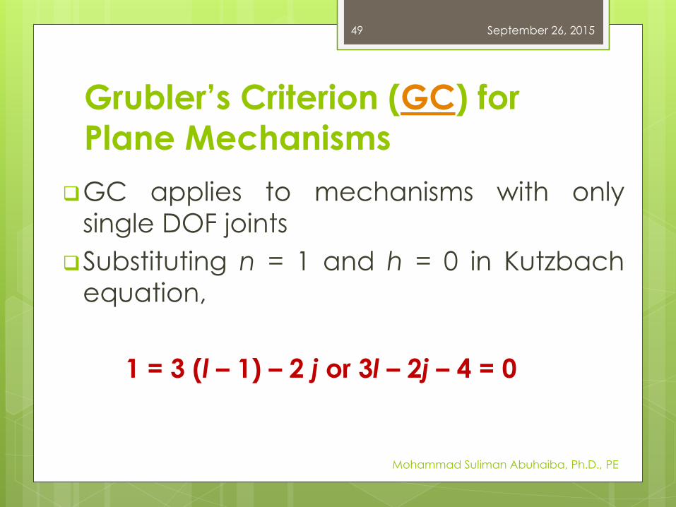
Grubler’s Criterion (GC) for
Plane Mechanisms
GC applies to mechanisms with only
single DOF joints
Substituting n = 1 and h = 0 in Kutzbach
equation,
1 = 3 (l – 1) – 2 j or 3l – 2j – 4 = 0
September 26, 2015
Mohammad Suliman Abuhaiba, Ph.D., PE
49
Grubler’s Criterion (GC) for
Plane Mechanisms
A plane mechanism with a movability of 1
& only single DOF joints can not have odd
number of links.
Simplest possible mechanisms:
four bar mechanism
slider-crank mechanism
September 26, 2015
Mohammad Suliman Abuhaiba, Ph.D., PE
50
Types of Kinematic Chains
Three types of kinematic chains with
four lower pairs are considered:
1. Four bar chain
2. Single slider crank chain
3. Double slider crank chain
September 26, 2015
Mohammad Suliman Abuhaiba, Ph.D., PE
51
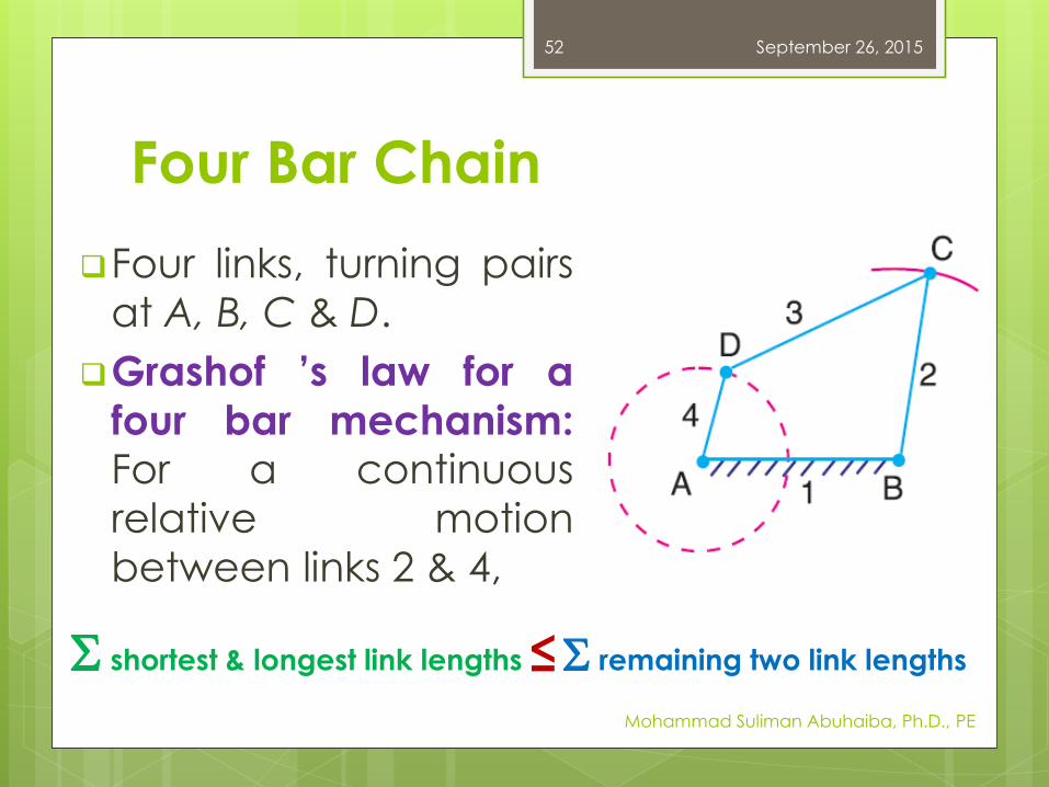
Four Bar Chain
Four links, turning pairs
at A, B, C & D.
Grashof ’s law for a
four bar mechanism:For a continuous
relative motion
between links 2 & 4,
September 26, 2015
Mohammad Suliman Abuhaiba, Ph.D., PE
52
S shortest & longest link lengths ≤S remaining two link lengths
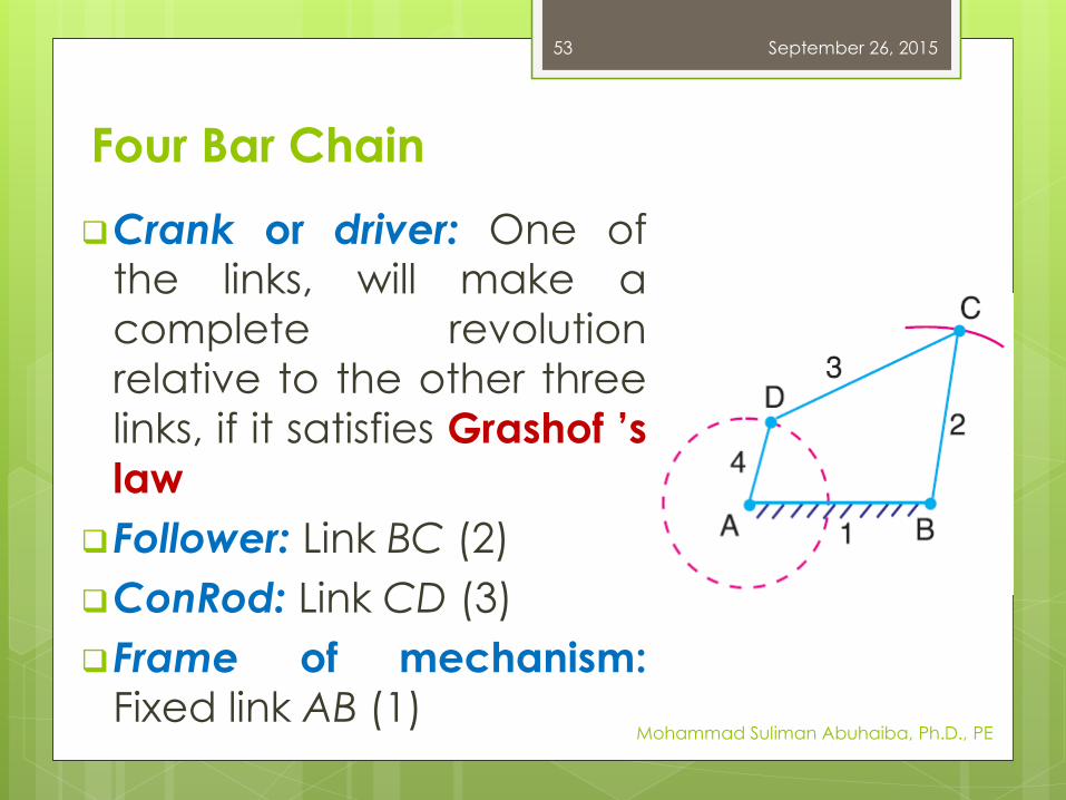
Four Bar Chain
Crank or driver: One ofthe links, will make a
complete revolution
relative to the other three
links, if it satisfies Grashof ’s
law
Follower: Link BC (2)
ConRod: Link CD (3)
Frame of mechanism:Fixed link AB (1)
September 26, 2015
Mohammad Suliman Abuhaiba, Ph.D., PE
53
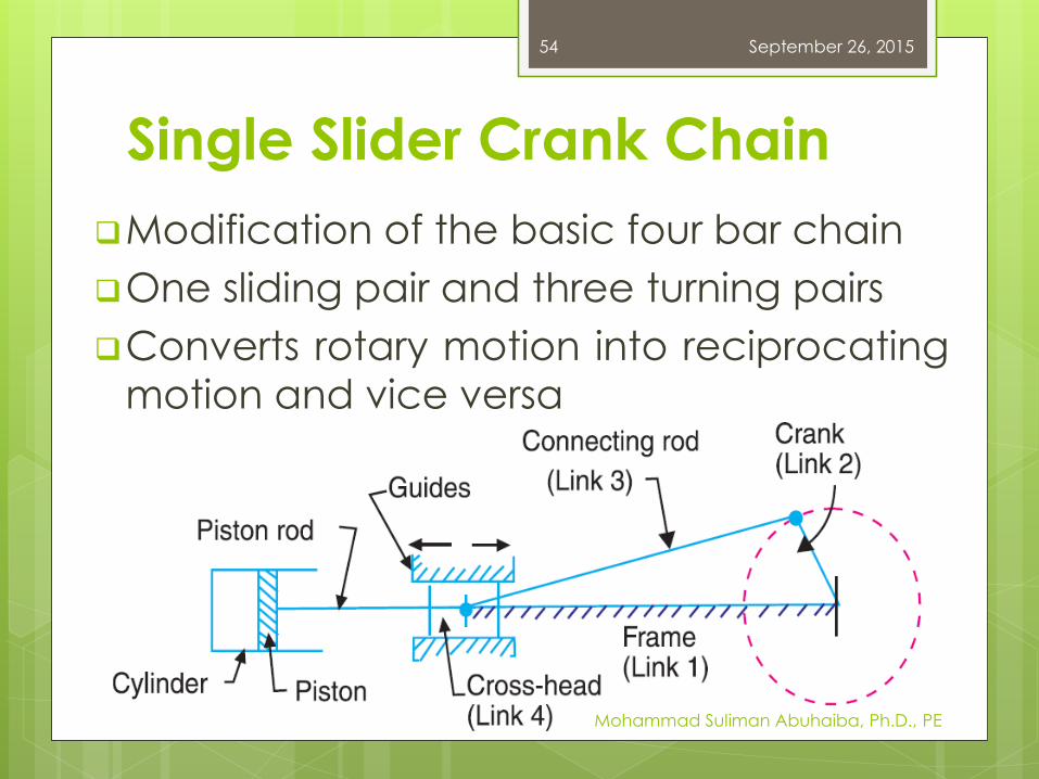
Single Slider Crank Chain
Modification of the basic four bar chain
One sliding pair and three turning pairs
Converts rotary motion into reciprocating
motion and vice versa
September 26, 2015
Mohammad Suliman Abuhaiba, Ph.D., PE
54
Inversion of Mechanism
Inversion of the mechanism:
method of obtaining different
mechanisms by fixing different links
in a kinematic chain
Relative motions between various links isnot changed, but their absolute motions
may be changed drastically
September 26, 2015
Mohammad Suliman Abuhaiba, Ph.D., PE
55
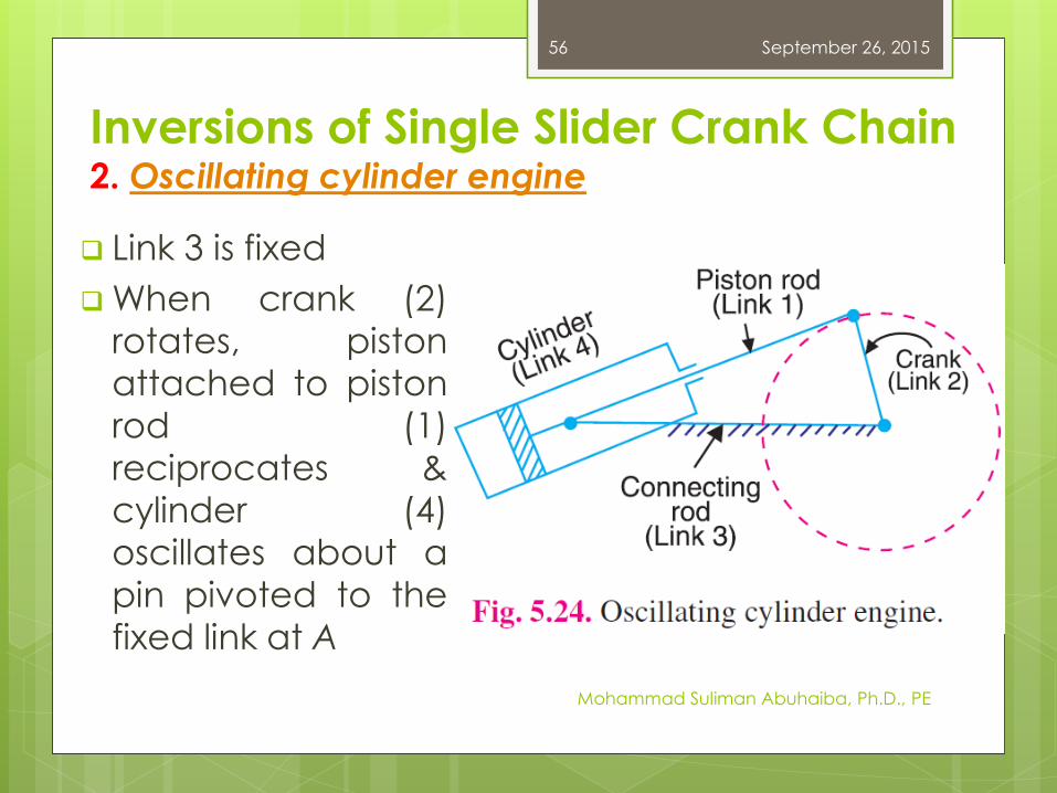
Inversions of Single Slider Crank Chain2. Oscillating cylinder engine
Link 3 is fixed
When crank (2)
rotates, piston
attached to piston
rod (1)
reciprocates &
cylinder (4)
oscillates about a
pin pivoted to the
fixed link at A
September 26, 2015
Mohammad Suliman Abuhaiba, Ph.D., PE
56
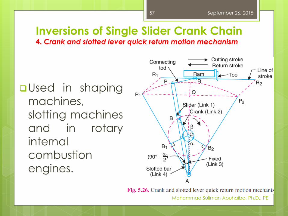
Inversions of Single Slider Crank Chain4. Crank and slotted lever quick return motion mechanism
Used in shaping
machines,
slotting machines
and in rotary
internal
combustion
engines.
September 26, 2015
Mohammad Suliman Abuhaiba, Ph.D., PE
57
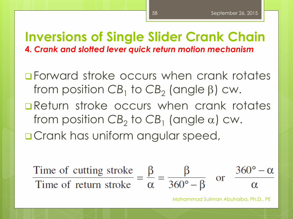
Inversions of Single Slider Crank Chain4. Crank and slotted lever quick return motion mechanism
Forward stroke occurs when crank rotates
from position CB1 to CB2 (angle b) cw.
Return stroke occurs when crank rotates
from position CB2 to CB1 (angle a) cw.
Crank has uniform angular speed,
September 26, 2015
Mohammad Suliman Abuhaiba, Ph.D., PE
58
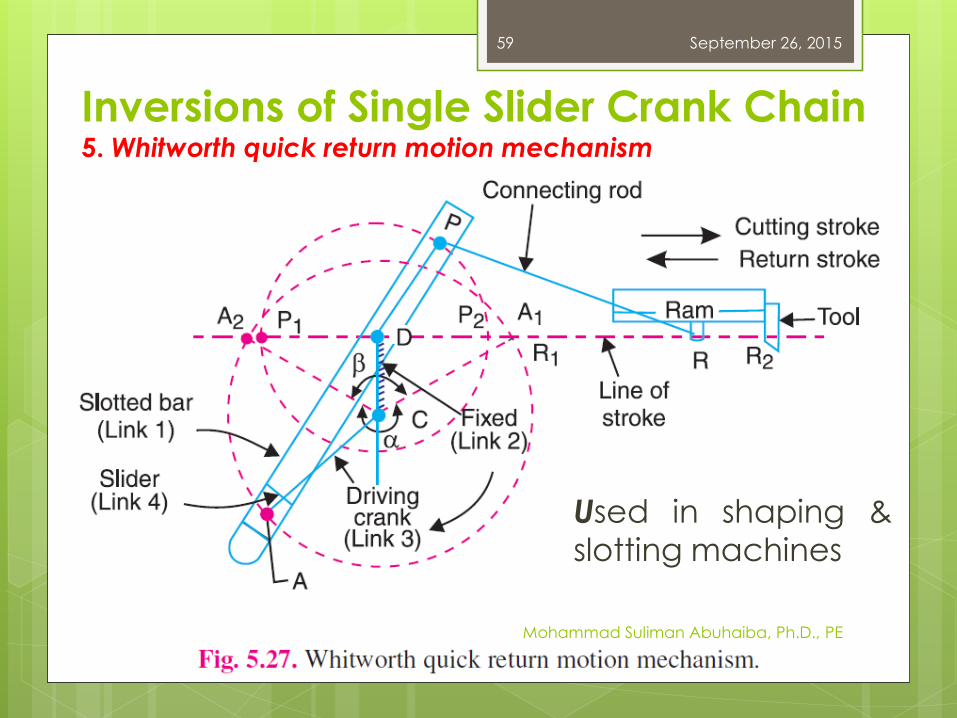
Inversions of Single Slider Crank Chain5. Whitworth quick return motion mechanism
September 26, 2015
Mohammad Suliman Abuhaiba, Ph.D., PE
59
Used in shaping &
slotting machines
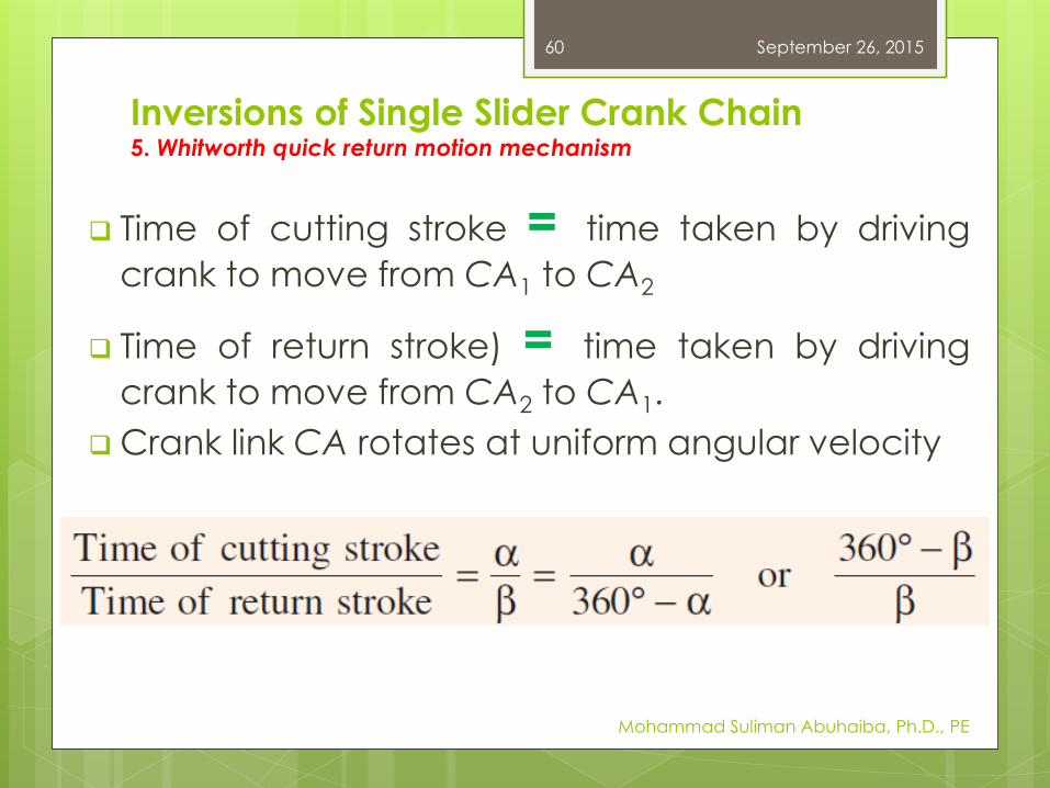
Time of cutting stroke = time taken by driving
crank to move from CA1 to CA2
Time of return stroke) = time taken by driving
crank to move from CA2 to CA1.
Crank link CA rotates at uniform angular velocity
Inversions of Single Slider Crank Chain5. Whitworth quick return motion mechanism
September 26, 2015
Mohammad Suliman Abuhaiba, Ph.D., PE
60
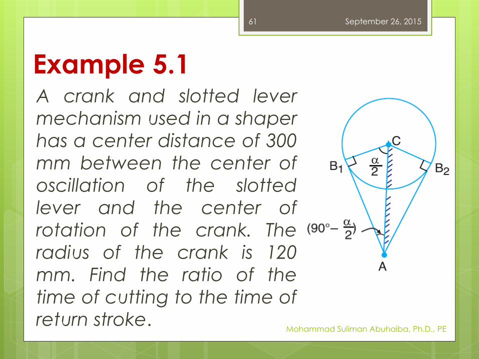
Example 5.1A crank and slotted lever
mechanism used in a shaper
has a center distance of 300
mm between the center of
oscillation of the slotted
lever and the center of
rotation of the crank. The
radius of the crank is 120
mm. Find the ratio of the
time of cutting to the time of
return stroke.
September 26, 2015
Mohammad Suliman Abuhaiba, Ph.D., PE
61
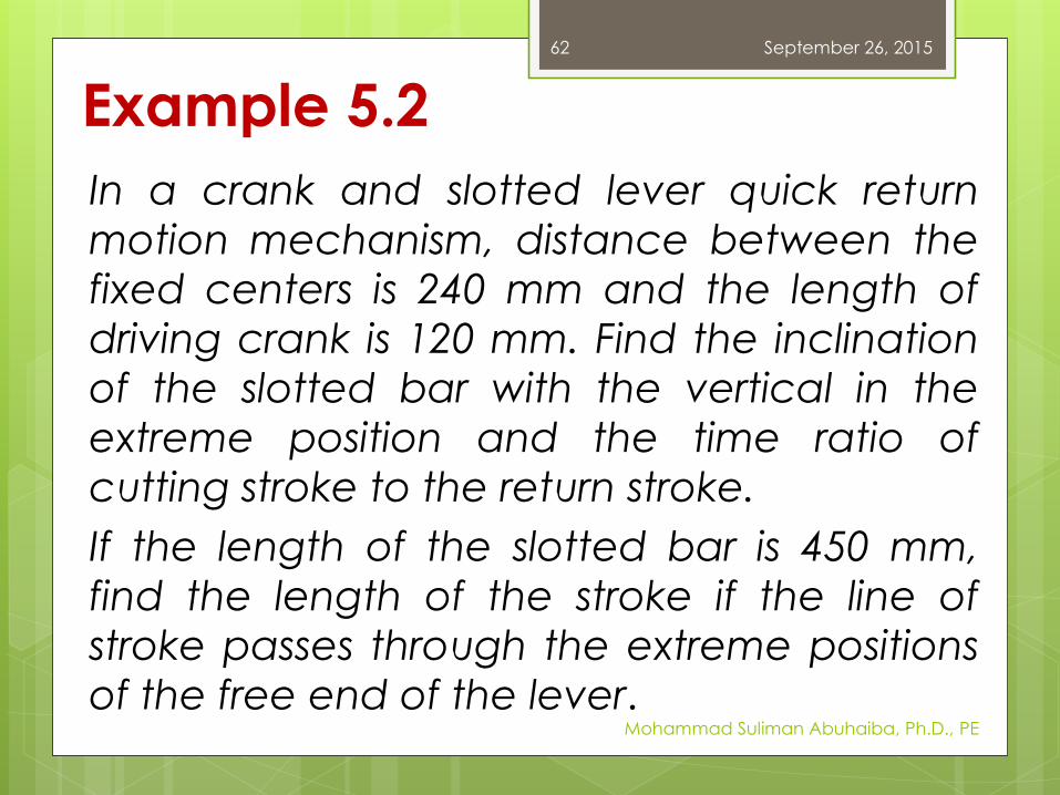
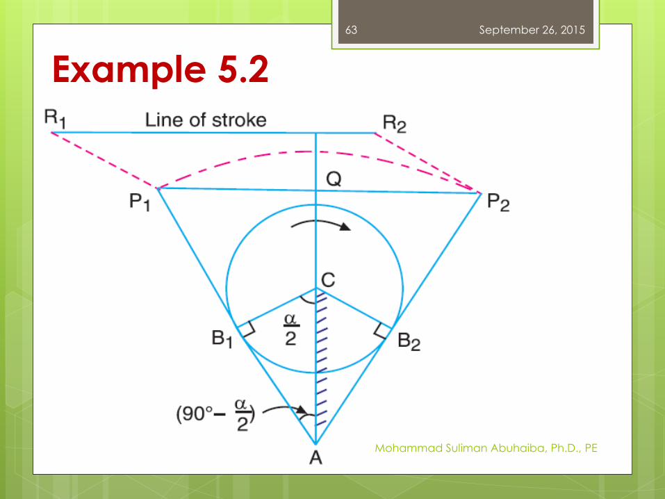
Example 5.2
In a crank and slotted lever quick return
motion mechanism, distance between the
fixed centers is 240 mm and the length of
driving crank is 120 mm. Find the inclination
of the slotted bar with the vertical in the
extreme position and the time ratio of
cutting stroke to the return stroke.
If the length of the slotted bar is 450 mm,
find the length of the stroke if the line of
stroke passes through the extreme positions
of the free end of the lever.
September 26, 2015
Mohammad Suliman Abuhaiba, Ph.D., PE
62
September 26, 2015
Mohammad Suliman Abuhaiba, Ph.D., PE
63
Example 5.2
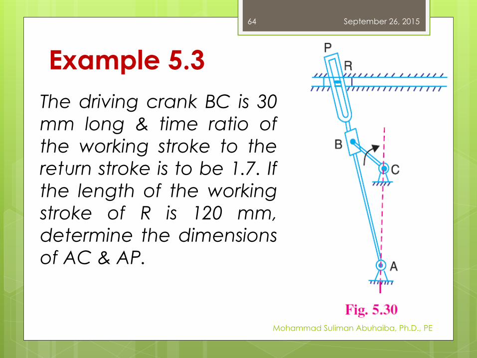
Example 5.3
The driving crank BC is 30
mm long & time ratio of
the working stroke to the
return stroke is to be 1.7. If
the length of the working
stroke of R is 120 mm,
determine the dimensions
of AC & AP.
September 26, 2015
Mohammad Suliman Abuhaiba, Ph.D., PE
64
September 26, 2015
Mohammad Suliman Abuhaiba, Ph.D., PE
65
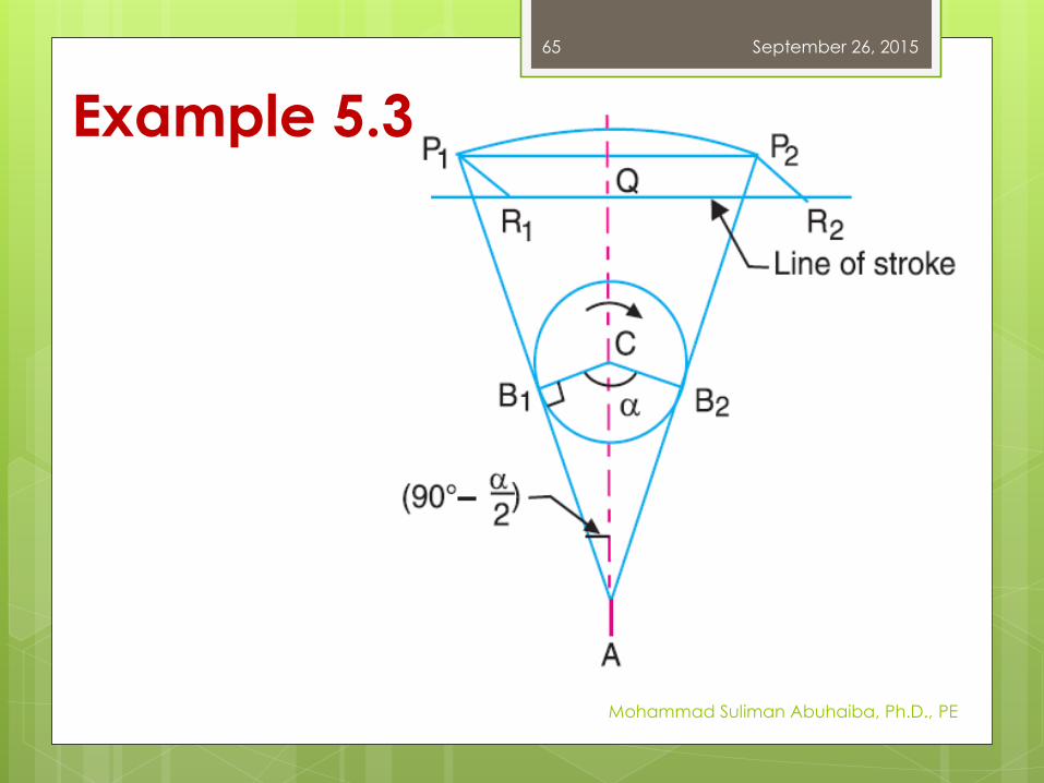
Example 5.3
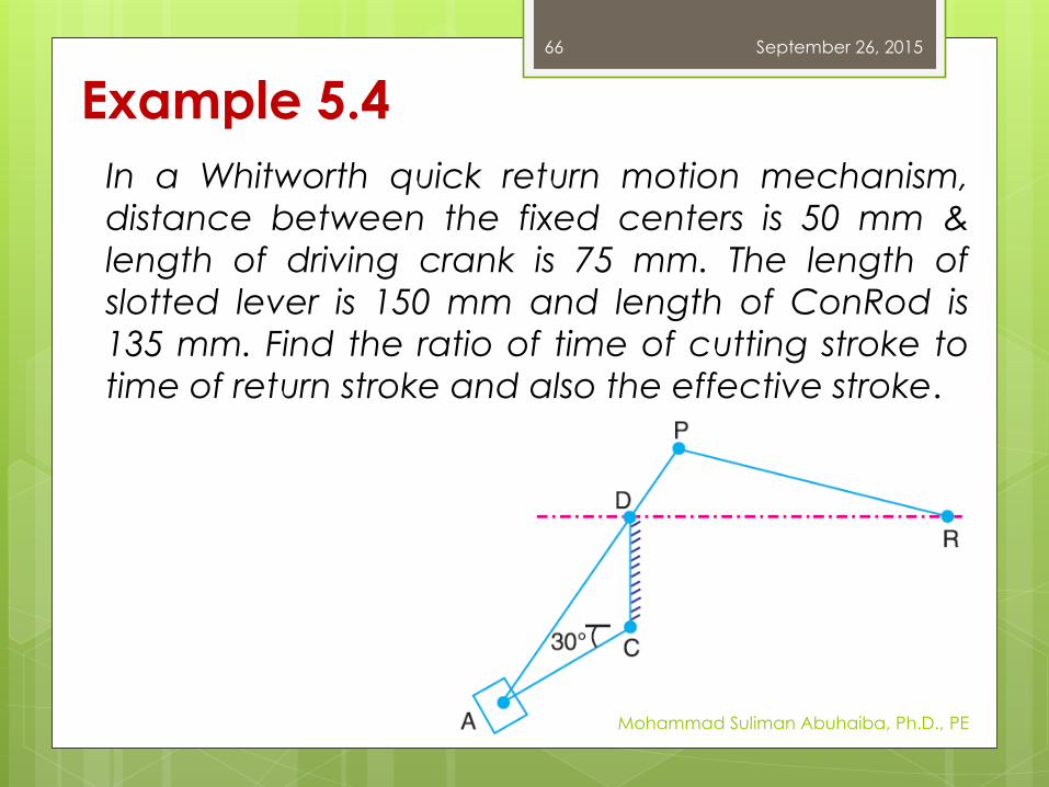
Example 5.4
In a Whitworth quick return motion mechanism,
distance between the fixed centers is 50 mm &
length of driving crank is 75 mm. The length of
slotted lever is 150 mm and length of ConRod is
135 mm. Find the ratio of time of cutting stroke to
time of return stroke and also the effective stroke.
September 26, 2015
Mohammad Suliman Abuhaiba, Ph.D., PE
66
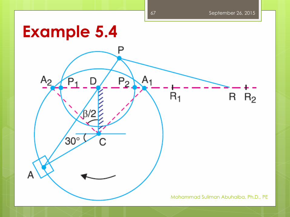
Example 5.4
September 26, 2015
Mohammad Suliman Abuhaiba, Ph.D., PE
67
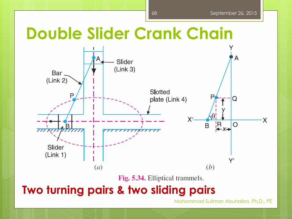
Double Slider Crank Chain
September 26, 2015
Mohammad Suliman Abuhaiba, Ph.D., PE
68
Two turning pairs & two sliding pairs
Inversions of Double Slider Crank Chain
1. Elliptical trammels
When links 1 & 3 slide along their
respective grooves, any point on
link 2 such as P traces out an ellipse
on the surface of link 4.
AP & BP are semi-major axis & mi-
minor axis of the ellipse.
September 26, 2015
Mohammad Suliman Abuhaiba, Ph.D., PE
69
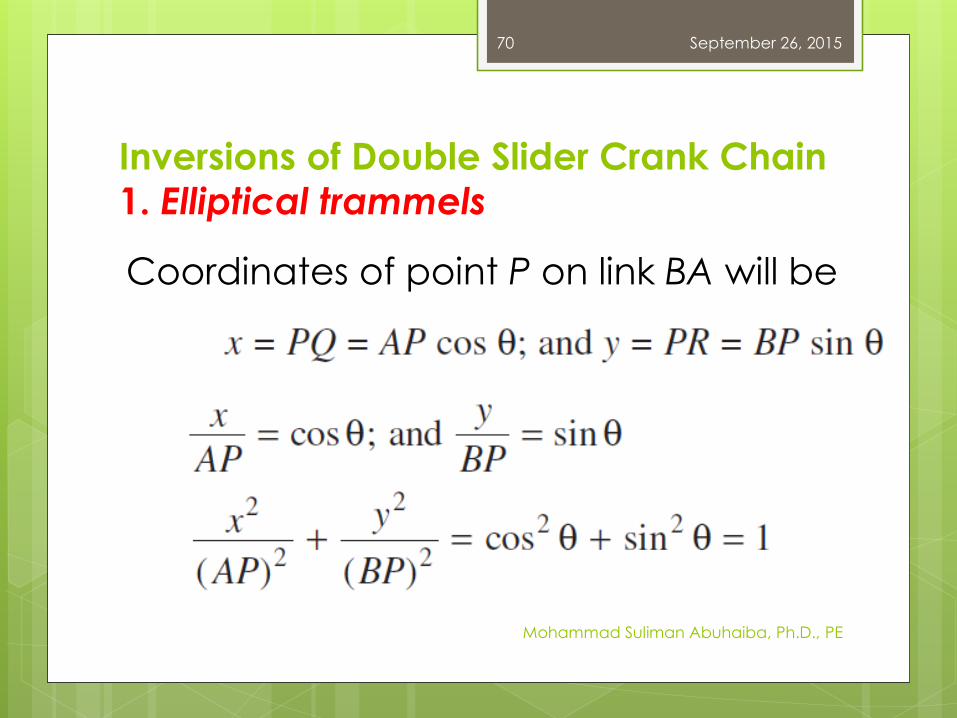
Inversions of Double Slider Crank Chain
1. Elliptical trammels
Coordinates of point P on link BA will be
September 26, 2015
Mohammad Suliman Abuhaiba, Ph.D., PE
70
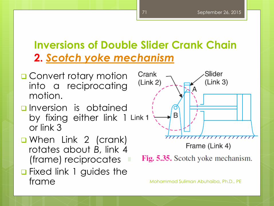
Inversions of Double Slider Crank Chain
2. Scotch yoke mechanism
Convert rotary motioninto a reciprocatingmotion.
Inversion is obtainedby fixing either link 1or link 3
When Link 2 (crank)rotates about B, link 4(frame) reciprocates
Fixed link 1 guides theframe
September 26, 2015
Mohammad Suliman Abuhaiba, Ph.D., PE
71
Inversions of Double Slider Crank Chain
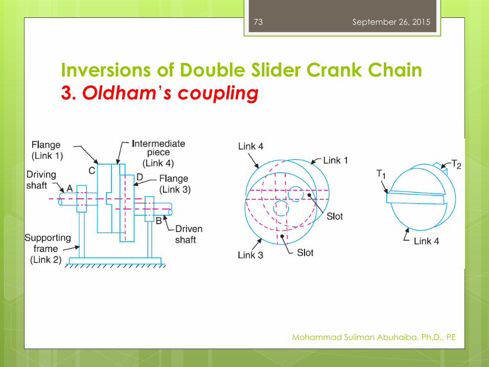
3. Oldham’s coupling
Used for connecting two parallel
shafts whose axes are at a small
distance apart
Inversion is obtained by fixing link 2,
Fig. 5.36 (a)
Shafts to be connected have two
flanges (link 1 & link 3) rigidly fastened
at their ends.
September 26, 2015
Mohammad Suliman Abuhaiba, Ph.D., PE
72
Inversions of Double Slider Crank Chain
3. Oldham’s coupling
September 26, 2015
Mohammad Suliman Abuhaiba, Ph.D., PE
73