Simple Machines 2.1 Introduction to Simple Machines
19
Simple Machines 2.1 Introduction to Simple Machines
Transcript of Simple Machines 2.1 Introduction to Simple Machines

Simple Machines 2.1 Introduction to Simple Machines

Simple Machines 2.1 Introduction to Simple Machines
Simple Machines Unit
DO NOT WRITE ANYWHERE IN THIS PACKAGE
One of the few properties that separate us from animals is our ability to make and use tools or machines
to make our lives easier. All complex machines (cars, bicycles, tools, etc.) can be broken down into a
collection of smaller machines … called simple machines. In this unit we will be exploring the properties
of many of the simple machines and we will be looking at how these machines can work together to
make our lives easier.
Big Picture Questions:
What are the different types of simple machines?
How does a simple machine impact the amount of work performed by the user?
What is mechanical advantage? Is there a difference between the ideal mechanical advantage
(IMA) and the actual mechanical advantage (AMA)?
How can an inclined plane be used to make work easier to perform?
What are the three classes of levers? How do they relate to each other?
How can we predict the mechanical advantage of a block and tackle just by looking at the way it
is put together?
Why can all of the simple machines be grouped into one of two groups?
How can the simple machines work together to form a complex machine?
Given several measurements, how can we calculate the mechanical advantage of an inclined
plane? A lever arm? A pulley system?
Simple Machines 2.1 Introduction to Simple Machines
Introduction to Simple Machines
Working with your group, discuss the answers to each of the questions below. Record your answers in
your notebook.
1. Define the following terms in your own words. Use examples or diagrams when applicable.
Simple Machine
Complex Machine
Mechanical advantage
Force
Torque
Efficiency
Work
2. Research the 6 different types of simple machines (for example: the inclined plane). List the 6
types of simple machines and give a real world example for each. It is best to try to find an
example or application that you would see in your life. For example I wouldn’t use the sand
ramp that the ancient Egyptians used to build the pyramid as an example of an application of
the inclined plane.
3. Even though there are six different types of simple machines, all simple machines can be
grouped together into one of two possible groups … the lever and the inclined plane. Place the
6 types of simple machines into the appropriate grouping. Create a table like the below
example. Explain your grouping for each of the simple machines.
The Lever Group The Inclined Plane Group
4. Simple machines make work easier to perform BUT they have no impact on the amount of work
done on the system. Explain this statement.
Simple Machines 2.2 Inclined Plane
Inclined Plane Activity
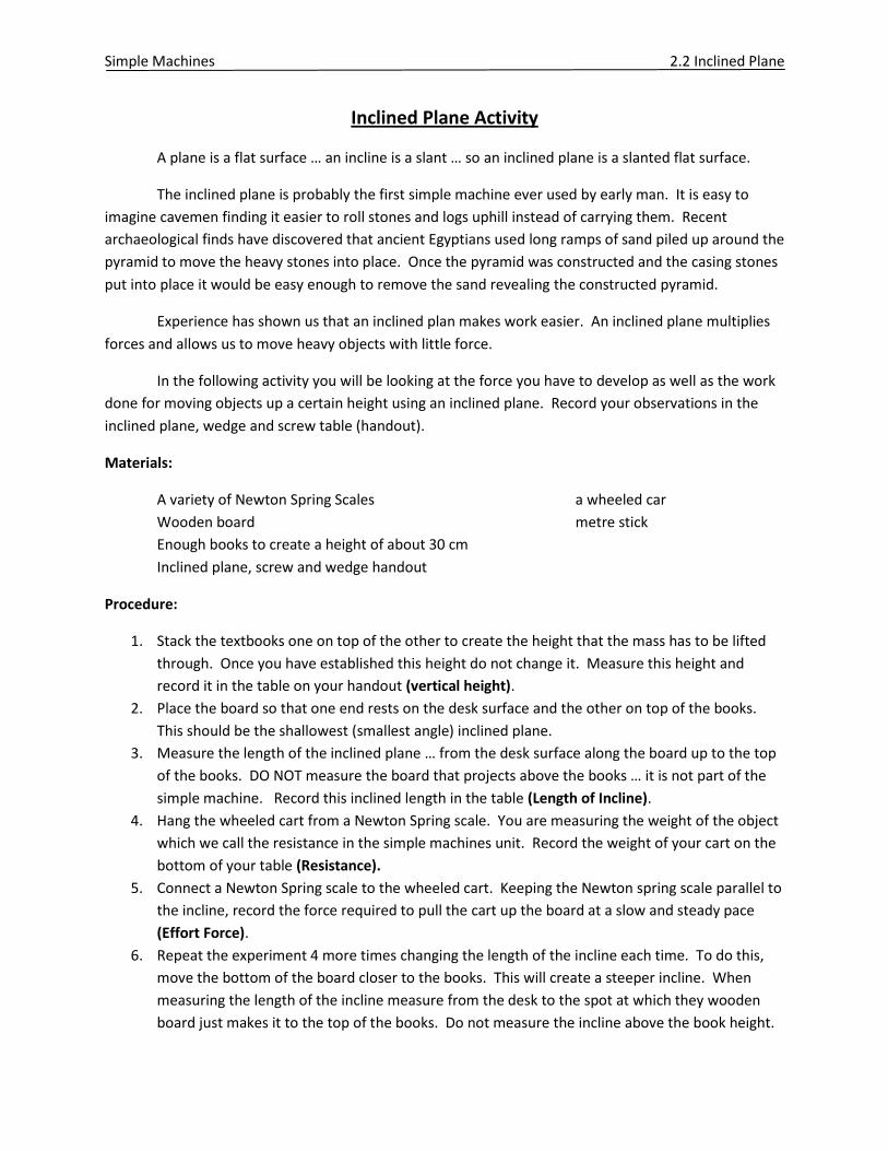
A plane is a flat surface … an incline is a slant … so an inclined plane is a slanted flat surface.
The inclined plane is probably the first simple machine ever used by early man. It is easy to
imagine cavemen finding it easier to roll stones and logs uphill instead of carrying them. Recent
archaeological finds have discovered that ancient Egyptians used long ramps of sand piled up around the
pyramid to move the heavy stones into place. Once the pyramid was constructed and the casing stones
put into place it would be easy enough to remove the sand revealing the constructed pyramid.
Experience has shown us that an inclined plan makes work easier. An inclined plane multiplies
forces and allows us to move heavy objects with little force.
In the following activity you will be looking at the force you have to develop as well as the work
done for moving objects up a certain height using an inclined plane. Record your observations in the
inclined plane, wedge and screw table (handout).
Materials:
A variety of Newton Spring Scales a wheeled car
Wooden board metre stick
Enough books to create a height of about 30 cm
Inclined plane, screw and wedge handout
Procedure:
1. Stack the textbooks one on top of the other to create the height that the mass has to be lifted
through. Once you have established this height do not change it. Measure this height and
record it in the table on your handout (vertical height).
2. Place the board so that one end rests on the desk surface and the other on top of the books.
This should be the shallowest (smallest angle) inclined plane.
3. Measure the length of the inclined plane … from the desk surface along the board up to the top
of the books. DO NOT measure the board that projects above the books … it is not part of the
simple machine. Record this inclined length in the table (Length of Incline).
4. Hang the wheeled cart from a Newton Spring scale. You are measuring the weight of the object
which we call the resistance in the simple machines unit. Record the weight of your cart on the
bottom of your table (Resistance).
5. Connect a Newton Spring scale to the wheeled cart. Keeping the Newton spring scale parallel to
the incline, record the force required to pull the cart up the board at a slow and steady pace
(Effort Force).
6. Repeat the experiment 4 more times changing the length of the incline each time. To do this,
move the bottom of the board closer to the books. This will create a steeper incline. When
measuring the length of the incline measure from the desk to the spot at which they wooden
board just makes it to the top of the books. Do not measure the incline above the book height.
Simple Machines 2.2 Inclined Plane
7. For the sixth row measure the force required to lift the 1 kg mass straight up. This is the effort
required if no simple machine were used.
8. Calculate the mechanical advantage by using the equation MA = resistance / effort. Resistance
is the force of gravity acting on the object (measured in procedure 7). Effort is the force
required to drag the mass up the incline as measured by the Newton spring scale. Record your
answers on the table.
9. Calculate inclined length / height and record this in your table.
Simple Machines 2.2 Inclined Planes
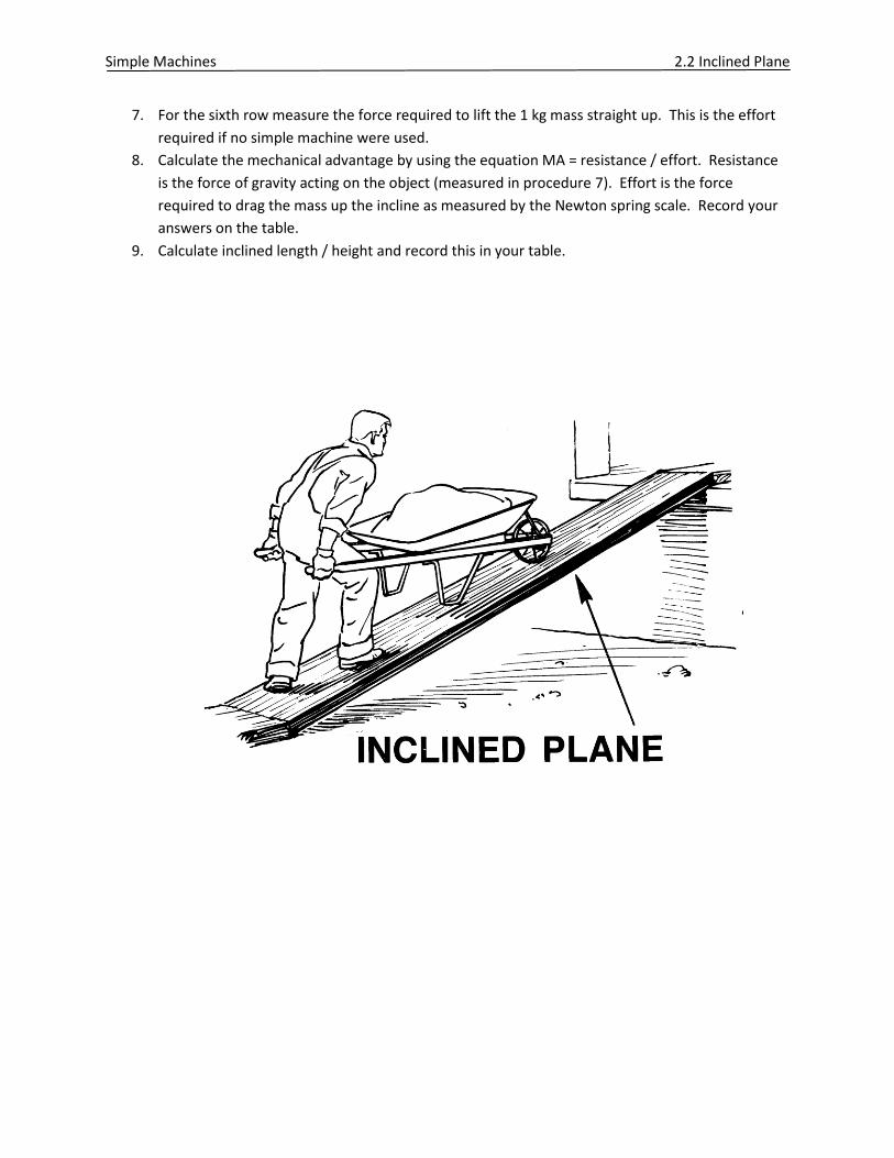
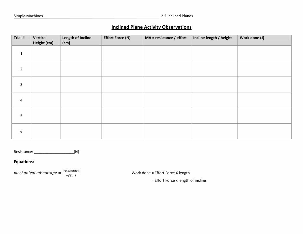
Inclined Plane Activity Observations
Trial # Vertical Height (cm)
Length of Incline (cm)
Effort Force (N) MA = resistance / effort Incline length / height Work done (J)
1
2
3
4
5
6
Resistance: ___________________(N)
Equations:
Work done = Effort Force X length
= Effort Force x length of incline
Simple Machines 2.2 Inclined Planes
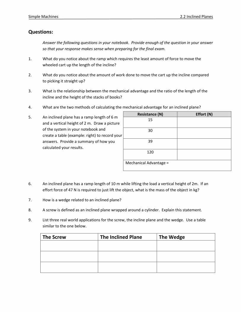
Resistance (N) Effort (N)
15
30
39
120
Mechanical Advantage =
Questions:
Answer the following questions in your notebook. Provide enough of the question in your answer
so that your response makes sense when preparing for the final exam.
1. What do you notice about the ramp which requires the least amount of force to move the
wheeled cart up the length of the incline?
2. What do you notice about the amount of work done to move the cart up the incline compared
to picking it straight up?
3. What is the relationship between the mechanical advantage and the ratio of the length of the
incline and the height of the stacks of books?
4. What are the two methods of calculating the mechanical advantage for an inclined plane?
5. An inclined plane has a ramp length of 6 m
and a vertical height of 2 m. Draw a picture
of the system in your notebook and
create a table (example: right) to record your
answers. Provide a summary of how you
calculated your results.
6. An inclined plane has a ramp length of 10 m while lifting the load a vertical height of 2m. If an
effort force of 47 N is required to just lift the object, what is the mass of the object in kg?
7. How is a wedge related to an inclined plane?
8. A screw is defined as an inclined plane wrapped around a cylinder. Explain this statement.
9. List three real world applications for the screw, the incline plane and the wedge. Use a table
similar to the one below.
The Screw The Inclined Plane The Wedge
Simple Machines 2.3 First Class Levers
First Class Lever Activity
The lever:
Levers consist of a long straight object (such as a board) placed over a pivot point known as a
fulcrum. Three types of levers exist … first class, second class and third class. The placement of the
fulcrum in relation to the effort force is what distinguishes between the three types of levers.
Before we go any further in our study of levers it is important to look at some lever specific
terms. Research the two questions below and record your answers in your notebook.
1. Use your text/Internet to research the following terms: Effort, Resistance, Fulcrum, Effort Arm,
Resistance Arm.
2. Draw a simple diagram of a first class lever and label (use the terms above).
Lever Setup :
For the lever labs you will require the following materials: a metre sticks, retort rod and utility
clamp, a variety of newton spring scales, metal ruler clamp, 1kg mass and 2 string loops.
1. Place a metal ruler clamp over a metre stick so that the clamp is as close to the 50 cm mark as
possible. This will be the fulcrum point.
2. Hang the ruler from the utility clamp and adjust the metre stick until it is balanced.
3. To test the first class lever, place string loops on either end of the metre stick. These loops will
be the place at which we will test the effort force and resistance force.
4. The resistance arm is the distance from the fulcrum to the string loop where the mass is hung.
So if the mass loop is placed at the 65 cm mark with the fulcrum at the 50 cm mark that means
that the resistance arm is 15 cm.
5. The effort arm is the distance from the fulcrum to the string loop where you will apply a
downward force through the newton spring scale.
6. Refer to Table #1 (below) for placements of the newton spring scale and the resistance mass.
Use your observations to complete the table.
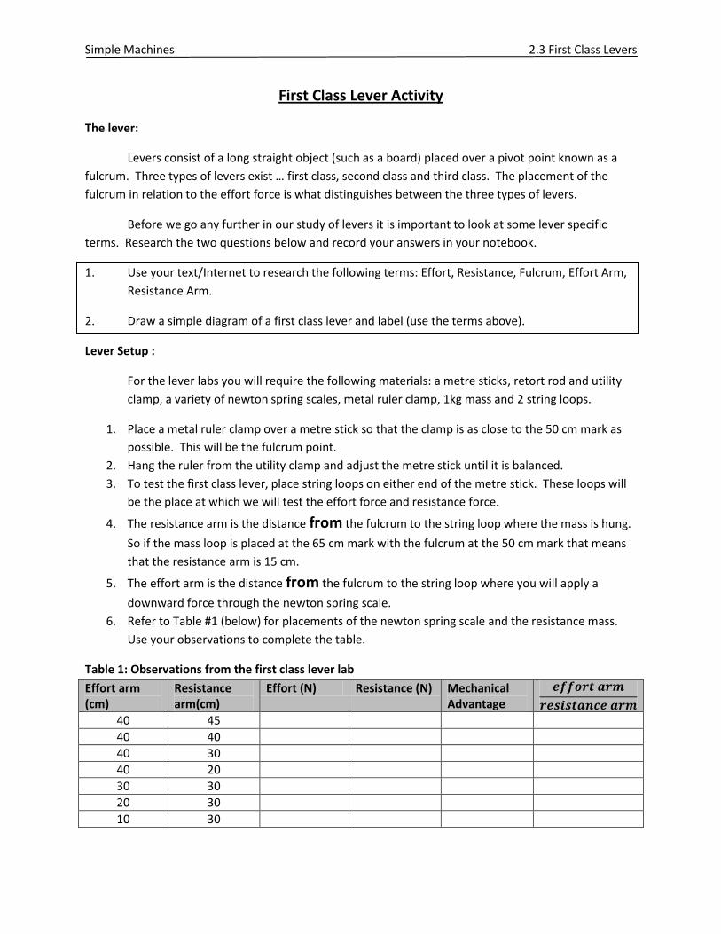
Table 1: Observations from the first class lever lab
Effort arm (cm)
Resistance arm(cm)
Effort (N) Resistance (N) Mechanical Advantage
40 45
40 40
40 30
40 20
30 30
20 30
10 30
Simple Machines 2.3 First Class Levers
Questions:
1. Compare the mechanical advantage to the ratio of the effort arm and the resistance arm. What
do you notice?
2. What happens to the mechanical advantage if the effort arm is larger than the resistance arm?
What would you use this lever for?
3. What happens to the mechanical advantage if the effort arm is smaller than the resistance arm?
What would you use this lever for?
4. What happens to the mechanical advantage if the effort arm is equal to the resistance arm?
What would you use this lever for?
5. How does the relationship between the effort arm and resistance arm change how far the mass
moves in the vertical when a force is applied?
6. Mr. Gillespie wishes to move a large stone out of his garden by using a long piece of 2x4. He
places one end of the 3 m long piece of wood under the stone and places a smaller rock 50 cm
from the end to act as a fulcrum. If the stone has a mass of 200 kg, what effort (in newtons)
does he have to exert to just lift the rock?
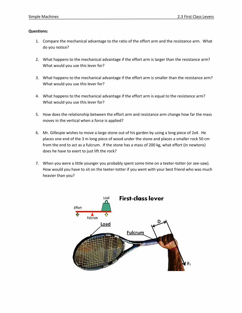
7. When you were a little younger you probably spent some time on a teeter-totter (or see-saw).
How would you have to sit on the teeter-totter if you went with your best friend who was much
heavier than you?
Simple Machines 2.4 Second Class Levers
Of the three classes of levers, the first class lever is the most versatile. By moving the fulcrum
closer to the resistance (making the effort arm longer) you can create a lever designed to
magnify your input force making work easier to perform. By moving the fulcrum further away
from the resistance (making the effort arm shorter) you can create a lever designed to magnify
the speed of an object’s motion.
The next two classes of lever, the second and third class, are not nearly as versatile. They are
designed to either magnify the input force OR to magnify the speed of the object.
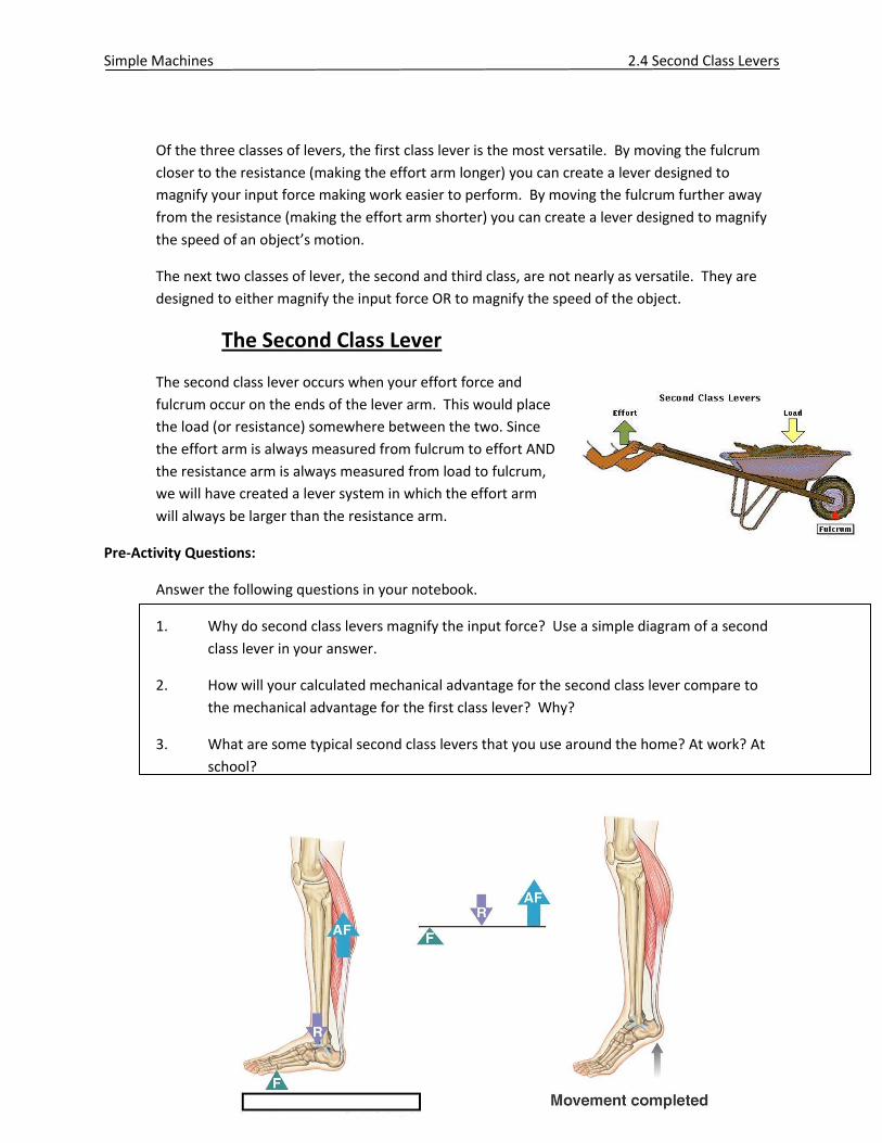
The Second Class Lever
The second class lever occurs when your effort force and
fulcrum occur on the ends of the lever arm. This would place
the load (or resistance) somewhere between the two. Since
the effort arm is always measured from fulcrum to effort AND
the resistance arm is always measured from load to fulcrum,
we will have created a lever system in which the effort arm
will always be larger than the resistance arm.
Pre-Activity Questions:
Answer the following questions in your notebook.
1. Why do second class levers magnify the input force? Use a simple diagram of a second
class lever in your answer.
2. How will your calculated mechanical advantage for the second class lever compare to
the mechanical advantage for the first class lever? Why?
3. What are some typical second class levers that you use around the home? At work? At
school?
Simple Machines 2.4 Second Class Levers
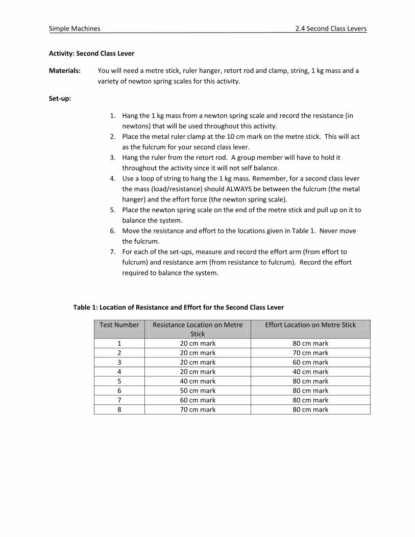
Activity: Second Class Lever
Materials: You will need a metre stick, ruler hanger, retort rod and clamp, string, 1 kg mass and a
variety of newton spring scales for this activity.
Set-up:
1. Hang the 1 kg mass from a newton spring scale and record the resistance (in
newtons) that will be used throughout this activity.
2. Place the metal ruler clamp at the 10 cm mark on the metre stick. This will act
as the fulcrum for your second class lever.
3. Hang the ruler from the retort rod. A group member will have to hold it
throughout the activity since it will not self balance.
4. Use a loop of string to hang the 1 kg mass. Remember, for a second class lever
the mass (load/resistance) should ALWAYS be between the fulcrum (the metal
hanger) and the effort force (the newton spring scale).
5. Place the newton spring scale on the end of the metre stick and pull up on it to
balance the system.
6. Move the resistance and effort to the locations given in Table 1. Never move
the fulcrum.
7. For each of the set-ups, measure and record the effort arm (from effort to
fulcrum) and resistance arm (from resistance to fulcrum). Record the effort
required to balance the system.
Table 1: Location of Resistance and Effort for the Second Class Lever
Test Number Resistance Location on Metre Stick
Effort Location on Metre Stick
1 20 cm mark 80 cm mark
2 20 cm mark 70 cm mark
3 20 cm mark 60 cm mark
4 20 cm mark 40 cm mark
5 40 cm mark 80 cm mark
6 50 cm mark 80 cm mark
7 60 cm mark 80 cm mark
8 70 cm mark 80 cm mark

Simple Machines 2.4 Second Class Levers
Questions:
1. Record your findings in a table similar to the one below:
Table 1: Observations from the second class lever lab
Effort arm (cm)
Resistance arm(cm)
Effort (N) Resistance (N) Mechanical Advantage
2. Did your findings indicate that the second class lever always makes work easier to
perform? What proof (from the above chart) do you have?
3. What are the two methods that you can use to calculate the mechanical advantage of a
second class lever system?
4. How are the two methods of calculating the mechanical advantage similar to the first
class lever? How are they different?
5. The ideal mechanical advantage (IMA) is the best possible situation. This is a calculated
value that ignores friction, air resistance and energy loss. Which calculation (from table
1) represents the IMA?
6. The actual mechanical advantage (AMA) is what actually happens. This calculation
includes external forces, friction, energy loss, etc. Which calculation (from table 1)
represents the AMA?

Simple Machines 2.5 Third Class Levers
The Third Class Lever
The third class lever occurs when your resistance force and
fulcrum occur on the ends of the lever arm. This would place the
effort force somewhere between the two. Since the effort arm is
always measured from fulcrum to effort AND the resistance arm is
always measured from load to fulcrum, we will have created a
lever system in which the effort arm will always be smaller than
the resistance arm.
Pre-Activity Questions:
Answer the following questions in your notebook.
1. Why do third class levers magnify the movement at the load end? Use a simple diagram
of a third class lever in your answer.
2. How will your calculated mechanical advantage for the third class lever compare to the
mechanical advantage for the other classes of lever? Why?
3. What are some typical third class levers that you use around the home? At work? At
school?
4. As the third class lever increases the speed of motion, what will happen to the effort
force required to complete the task? Why?
Simple Machines 2.5 Third Class Levers
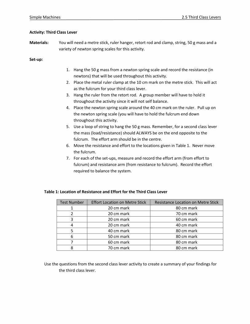
Activity: Third Class Lever
Materials: You will need a metre stick, ruler hanger, retort rod and clamp, string, 50 g mass and a
variety of newton spring scales for this activity.
Set-up:
1. Hang the 50 g mass from a newton spring scale and record the resistance (in
newtons) that will be used throughout this activity.
2. Place the metal ruler clamp at the 10 cm mark on the metre stick. This will act
as the fulcrum for your third class lever.
3. Hang the ruler from the retort rod. A group member will have to hold it
throughout the activity since it will not self balance.
4. Place the newton spring scale around the 40 cm mark on the ruler. Pull up on
the newton spring scale (you will have to hold the fulcrum end down
throughout this activity.
5. Use a loop of string to hang the 50 g mass. Remember, for a second class lever
the mass (load/resistance) should ALWAYS be on the end opposite to the
fulcrum. The effort arm should be in the centre.
6. Move the resistance and effort to the locations given in Table 1. Never move
the fulcrum.
7. For each of the set-ups, measure and record the effort arm (from effort to
fulcrum) and resistance arm (from resistance to fulcrum). Record the effort
required to balance the system.
Table 1: Location of Resistance and Effort for the Third Class Lever
Test Number Effort Location on Metre Stick Resistance Location on Metre Stick
1 20 cm mark 80 cm mark
2 20 cm mark 70 cm mark
3 20 cm mark 60 cm mark
4 20 cm mark 40 cm mark
5 40 cm mark 80 cm mark
6 50 cm mark 80 cm mark
7 60 cm mark 80 cm mark
8 70 cm mark 80 cm mark
Use the questions from the second class lever activity to create a summary of your findings for
the third class lever.
Simple Machines 2.6 Mathematics and Simple Machines
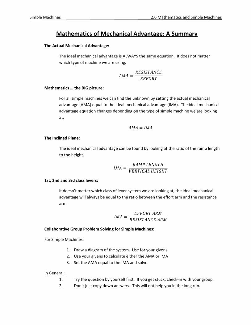
Mathematics of Mechanical Advantage: A Summary
The Actual Mechanical Advantage:
The ideal mechanical advantage is ALWAYS the same equation. It does not matter
which type of machine we are using.
Mathematics … the BIG picture:
For all simple machines we can find the unknown by setting the actual mechanical
advantage (AMA) equal to the ideal mechanical advantage (IMA). The ideal mechanical
advantage equation changes depending on the type of simple machine we are looking
at.
The Inclined Plane:
The ideal mechanical advantage can be found by looking at the ratio of the ramp length
to the height.
1st, 2nd and 3rd class levers:
It doesn’t matter which class of lever system we are looking at, the ideal mechanical
advantage will always be equal to the ratio between the effort arm and the resistance
arm.
Collaborative Group Problem Solving for Simple Machines:
For Simple Machines:
1. Draw a diagram of the system. Use for your givens
2. Use your givens to calculate either the AMA or IMA
3. Set the AMA equal to the IMA and solve.
In General:
1. Try the question by yourself first. If you get stuck, check-in with your group.
2. Don’t just copy down answers. This will not help you in the long run.
Simple Machines 2.6 Mathematics and Simple Machines
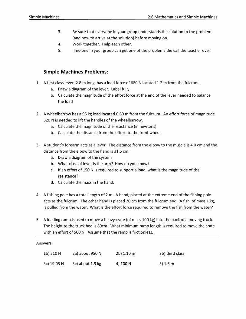
3. Be sure that everyone in your group understands the solution to the problem
(and how to arrive at the solution) before moving on.
4. Work together. Help each other.
5. If no one in your group can get one of the problems the call the teacher over.
Simple Machines Problems:
1. A first class lever, 2.8 m long, has a load force of 680 N located 1.2 m from the fulcrum.
a. Draw a diagram of the lever. Label fully
b. Calculate the magnitude of the effort force at the end of the lever needed to balance
the load
2. A wheelbarrow has a 95 kg load located 0.60 m from the fulcrum. An effort force of magnitude
520 N is needed to lift the handles of the wheelbarrow.
a. Calculate the magnitude of the resistance (in newtons)
b. Calculate the distance from the effort to the front wheel
3. A student’s forearm acts as a lever. The distance from the elbow to the muscle is 4.0 cm and the
distance from the elbow to the hand is 31.5 cm.
a. Draw a diagram of the system
b. What class of lever is the arm? How do you know?
c. If an effort of 150 N is required to support a load, what is the magnitude of the
resistance?
d. Calculate the mass in the hand.
4. A fishing pole has a total length of 2 m. A hand, placed at the extreme end of the fishing pole
acts as the fulcrum. The other hand is placed 20 cm from the fulcrum end. A fish, of mass 1 kg,
is pulled from the water. What is the effort force required to remove the fish from the water?
5. A loading ramp is used to move a heavy crate (of mass 100 kg) into the back of a moving truck.
The height to the truck bed is 80cm. What minimum ramp length is required to move the crate
with an effort of 500 N. Assume that the ramp is frictionless.
Answers:
1b) 510 N 2a) about 950 N 2b) 1.10 m 3b) third class
3c) 19.05 N 3c) about 1.9 kg 4) 100 N 5) 1.6 m
Simple Machines 2.7 The Pulley
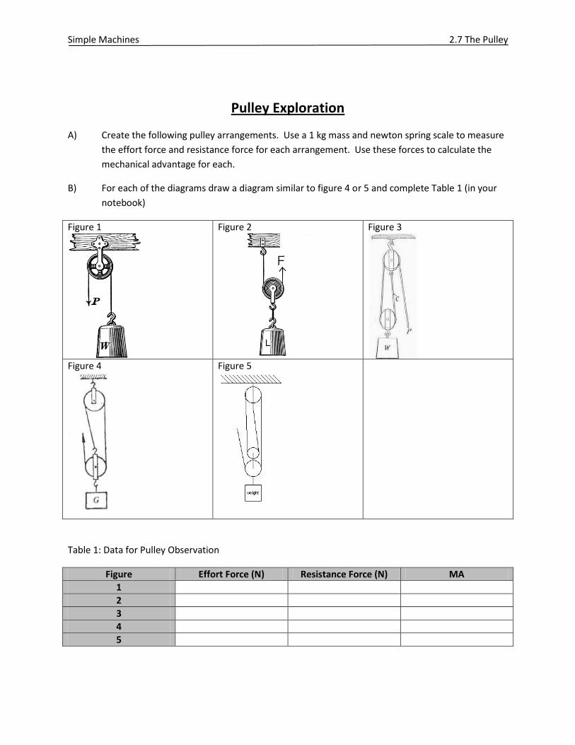
Pulley Exploration
A) Create the following pulley arrangements. Use a 1 kg mass and newton spring scale to measure
the effort force and resistance force for each arrangement. Use these forces to calculate the
mechanical advantage for each.
B) For each of the diagrams draw a diagram similar to figure 4 or 5 and complete Table 1 (in your
notebook)
Figure 1
Figure 2
Figure 3
Figure 4
Figure 5
Table 1: Data for Pulley Observation
Figure Effort Force (N) Resistance Force (N) MA
1
2
3
4
5
Simple Machines 2.7 The Pulley
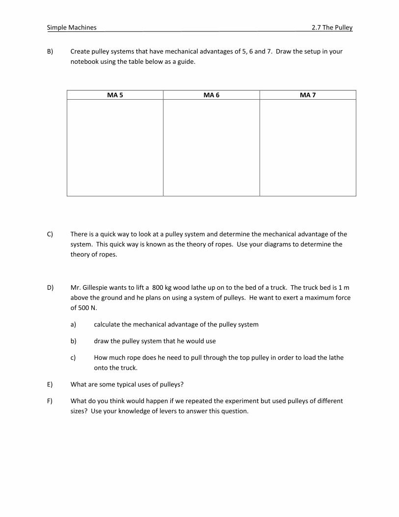
B) Create pulley systems that have mechanical advantages of 5, 6 and 7. Draw the setup in your
notebook using the table below as a guide.
MA 5 MA 6 MA 7
C) There is a quick way to look at a pulley system and determine the mechanical advantage of the
system. This quick way is known as the theory of ropes. Use your diagrams to determine the
theory of ropes.
D) Mr. Gillespie wants to lift a 800 kg wood lathe up on to the bed of a truck. The truck bed is 1 m
above the ground and he plans on using a system of pulleys. He want to exert a maximum force
of 500 N.
a) calculate the mechanical advantage of the pulley system
b) draw the pulley system that he would use
c) How much rope does he need to pull through the top pulley in order to load the lathe
onto the truck.
E) What are some typical uses of pulleys?
F) What do you think would happen if we repeated the experiment but used pulleys of different
sizes? Use your knowledge of levers to answer this question.
Simple Machines 2.8 The End of Unit Project
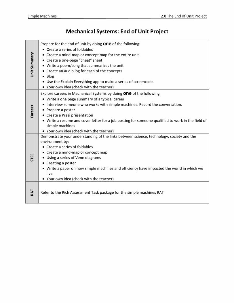
Mechanical Systems: End of Unit Project U
nit
Su
mm
ary
Prepare for the end of unit by doing one of the following:
Create a series of foldables
Create a mind-map or concept map for the entire unit
Create a one-page “cheat” sheet
Write a poem/song that summarizes the unit
Create an audio log for each of the concepts
Blog
Use the Explain Everything app to make a series of screencasts
Your own idea (check with the teacher)
Car
ee
rs
Explore careers in Mechanical Systems by doing one of the following:
Write a one page summary of a typical career
Interview someone who works with simple machines. Record the conversation.
Prepare a poster
Create a Prezi presentation
Write a resume and cover letter for a job posting for someone qualified to work in the field of simple machines
Your own idea (check with the teacher)
STSE
Demonstrate your understanding of the links between science, technology, society and the environment by:
Create a series of foldables
Create a mind-map or concept map
Using a series of Venn diagrams
Creating a poster
Write a paper on how simple machines and efficiency have impacted the world in which we live
Your own idea (check with the teacher)
RA
T
Refer to the Rich Assessment Task package for the simple machines RAT